

Page 1

59577-88
POCKET COLORIMETER™ II
ANALYSIS SYSTEMS
INSTRUCTION MANUAL
Iron
Molybdenum
Ozone
Zinc
© Hach Company, 2006. All rights reserved. Printed in the U.S.A. te/dk 12/06 3ed
Page 2

1—2
Important Note
This manual is intended for use with the following Pocket Colorimeter II
instruments:
The Pocket Colorimeter II instruments listed above are not interchangeable.
Iron Cat. No. 59530-16
Molybdenum Cat. No. 59530-10
Ozone Cat. No. 59530-04
Zinc Cat. No. 59530-09
Page 3

1—3
Table of Contents
Safety Precautions............................................................................................... 1—7
Laboratory Safety............................................................................................... 1—7
Use of Hazard Information................................................................................1—7
Precautionary Labels........ ....................................................... ....... ....................1—8
Specifications......................................................................................................... 1—9
Instrument Keys and Display..........................................................................1—13
Instrument Cap Cord.........................................................................................1—14
Iron, Total...............................................................................................................1—17
Measuring Hints ...............................................................................................1—17
Sampling and Storage......................................................................................1—26
Accuracy Check................ ....... ....................................................... ....... ...... .....1 —26
Standard Calibration Adjust Method...................... .......................................1—27
Method Performance........................................................................................1—27
Interferences......................................................................................................1—28
Summary of Method........................................................................................1—29
Reagents and Apparatus.................................................. ................................1—30
Page 4

1—4
Table of Contents, continued
Molybdenum, Molybdate, LR.........................................................................1—33
Measuring Hints................................................................................................1—33
Sampling and Storage......................................................................................1—38
Accuracy Check...................................... ....... ....... .............................................1—38
Interferences......................................................................................................1—38
Summary of Method.........................................................................................1—38
Replacement Parts.............................................................................................1—38
Molybdenum, Molybdate, HR.........................................................................1—39
Measuring Hints................................................................................................1—39
Sampling and Storage......................................................................................1—44
Accuracy Check...................................... ....... ....... .............................................1—44
Method Performance........................................................................................1—45
Standard Calibration Adjust Method..............................................................1—45
Interferences......................................................................................................1—46
Summary of Method.........................................................................................1—49
Ozone.......................................................................................................................1—53
Measuring Hints................................................................................................1—53
Sampling and Storage......................................................................................1—58
Stability of Indigo Reagent....................................... ....... ................................1—58
Page 5

1—5
Table of Contents, continued
Accuracy Check................ ....... ....................................................... ....... ...... .....1 —58
Spec
√™ Secondary Standards for Instrument Verification.............. ...... .....1 —5 9
Summary of Method........................................................................................1—61
Reagents and Apparatus.................................................. ................................1—62
Zinc...........................................................................................................................1—63
Measuring Hints ...............................................................................................1—63
Sampling and Storage......................................................................................1—68
Accuracy Check................ ....... ....................................................... ....... ...... .....1 —68
Method Performance........................................................................................1—69
Standard Calibration Adjust Method...................... .......................................1—69
Interferences......................................................................................................1—70
Waste Management..........................................................................................1—70
Summary of Method........................................................................................1—71
Reagents and Apparatus.................................................. ................................1—71
Instrument Operation.........................................................................................2—3
Key Functions..................................................... ....... ......................................... 2—3
Menu Selections.............................. ....................................................... ...... ....... 2—4
Switching Ranges...............................................................................................2—4
Setting the Time ................................................................................................. 2—4
Page 6

1—6
Table of Contents, continued
Recalling Stored Measurements........................................................................2—5
Battery Installation.............................................................................................2—6
Error Codes..............................................................................................................2—9
Error Messages ....................................................................................................2—9
Standard Calibration Adjust...........................................................................2—13
User-Entered Calibration.................................................................................2—15
Overview............................................................................................................2—15
Calibration Procedure Using Prepared Standards.........................................2—17
Entering a Predetermined Calibration Curve.......... .......................................2—20
Editing a User-entered or Factory Calibration Curve...................................2—22
Exiting the Calibration Routine......................... .............................................2—24
Deleting Calibration Points.......................... ....... ...... .......................................2—24
Retrieving the Factory Calibration ................................................................. 2 —25
Maximum/Minimum Displayed Value....................................................... ....2—26
Certification..........................................................................................................2—29
How to Order........................................................................................................2—35
Repair Service.......................................................................................................2—37
Warranty.................................................................................................................2—38
Page 7

1—7
Safety Precautions
Please read this entire manual before unpacking, setting up, or operating this
instrument. Pay particular attention to all danger and caution statements. Failure
to do so could result in serious injury to the operator or damage to the equipment.
To ensure the protection provided by this equipment is not impaired, do not use or
install this equipment in any manner other than that which is specified in
this manual.
Laboratory Safety
As part of good laboratory practice, pl eas e familiarize yourself with the reagents
used in these procedures. Read all product labels and the m aterial safety data
sheets (MSDS) before using them. It is always good practice to wear safety glasses
when handling chemicals. Foll ow instructions carefully. Rinse thoroughly if
contact occurs. If you have questions about reagents or procedures, please contact
the manufacturer or distributor.
Use of Hazard Information
If multiple hazards exist, this manu al wi ll use th e sign al wo rd (Danger, Caution,
Note) corresponding to the greatest hazard.
Page 8

1—8
Safety Precautions, continued
DANGER
Indicates a potentially or imminently hazardous situation which, if not
avoided, could result in death or serious injury.
CAUTION
Indicates a potentially hazardous situation that may result in minor or
moderate injury.
NOTE
Information that requires special emphasis.
Precautionary Labels
Please pay particular attention to labels and tags attached to the instrument.
Personal in ju ry or damage to the instrument could occur if not observed .
This symbol, if noted on the instrume n t, referen ces the instruct io n manual
for operational and/or safety inform ation.
Page 9

1—9
Specifications
Lamp: Light emitting diode (LED)
Detector: Silicon photodiode
Photometric precision: ± 0.0015 Abs
Filter bandwidth: 15 nm
Wavelength: 600 nm
Absorbance range: 0–2.5 Abs
Dimensions: 3.2 x 6.1 x 15.2 cm (1.25 x 2.4 x 6 inches)
Weight: 0.2 kg (0.43 lb)
Sample cells: 25 mm (10 mL), AccuVac
®
Ampuls
Operating conditions: 0 to 50 °C (32 to 122 °F); 0 to 90% relative humidity
(noncondensing)
Power supply: Four AAA alkaline batteries; approximate life is 2000 tests*
* Backlight usage will decrease battery life.
Page 10

1—10
Page 11

1—11
OPERATION
DANGER
Handling chemical samples, standards, and reagents can be dangerous. Review the necessary
Material Safety Data Sheets and become familiar with all safety procedures before handling
any chemicals.
DANGER
La manipulation des échantillons chimiques, étalons et réactifs peut être danger euse. Lir e les Fiches
de Données de Sécurité des Produits (FDSP) et se familiariser avec toutes les procédures de sécurité
avant de manipuler tous les produits chimiques.
PELIGRO
La manipulación de muestras químicas, estándares y reactivos puede ser peligro s a. Revi se las fichas
de seguridad de materiales y familiarícese con los procedimientos de seguridad antes de manipular
productos químicos.
GEFAHR
Das Arbeiten mit chemischen Proben, Standards und Reagenzien ist mit Gefahren verbunden. Es
wird dem Benutzer dieser Produkte empfohlen, sich vor der Arbeit mit sicheren Verfahrensweisen
und dem richtigen Gebrauch der Chemikalien vertraut zu machen und alle entsprechenden
Materialsicherheitsdatenblätter aufmerksam zu lesen.
PERIGO
A manipulação de amostras, padrões e reagentes químicos pode ser perigosa. Reveja a folha dos
dados de segurança do material e familiarize-se com todos os procedimentos de segurança antes
de manipular quaisquer produtos químicos.
PERICOLO
La manipolazione di campioni, standard e reattivi chimici può essere pericolosa. La preghiamo di
prendere conoscenza delle Schede Techniche necessarie legate alla Sicurezza dei Materiali e di
abituarsi con tutte le procedure di sicurezza prima di manipolare ogni prodotto chimico.
Page 12

1—12
Page 13
1—13
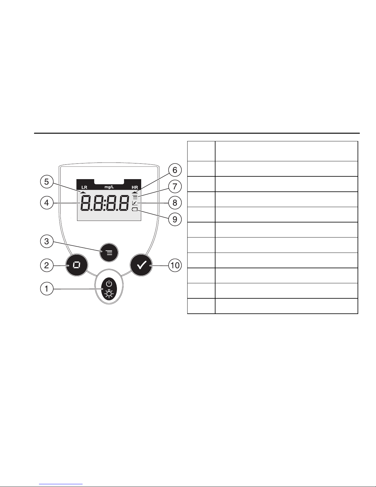
Instrument Keys and Display
Item
Description
1
POWER/BACKLIGHT Key
2
ZERO/SCROLL Key
3
MENU Key
4 Numeric Display
5 Range Indicator
6 Range Indicator
7 Menu Indicator
8 Calibration Adjusted Indicator
9 Battery Low Indicator
10
READ/ENTER Key
Page 14

1—14
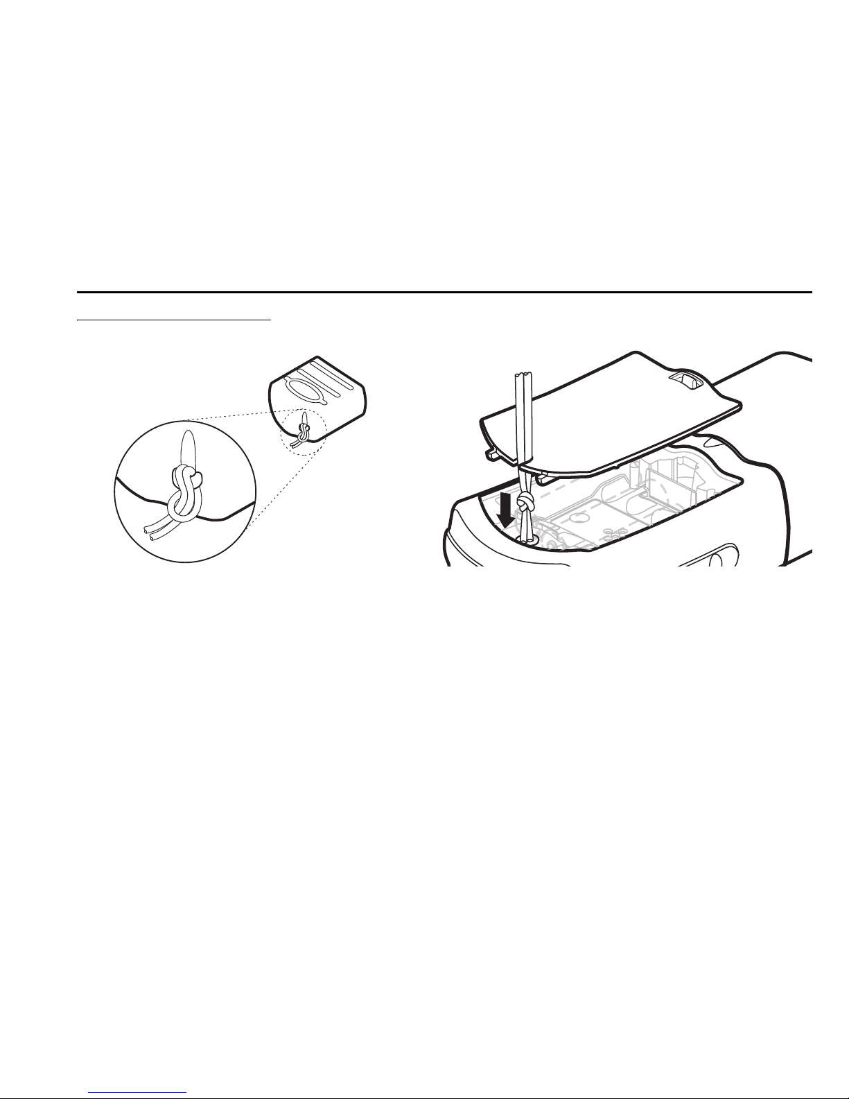
Instrument Cap Cord
The instrument cap for the Pocket Colorimeter™ II doubles as a light shield.
Accurate measurements cannot be obtained unless the sample or blan k is covered
with the cap. Use the instrument cap cord to secure the cap to the body of the
colorimeter and prevent loss of the cap. See Figu re 1 on page 1—15.
1. Loop the instrument cap cord through the ring on the cap.
2. Remove the battery compartment cover. Press the knotted end of the cord into
the hole indicated by the arro w.
3. Slide the cord into the slot on the battery compartment cover. Snap the cover
into place.
Page 15
1—15
Instrument Cap Cord, continued
Figure 1 Attaching the Instrument Cap Cord
Page 16

1—16
Page 17

1—17
Iron, Total (0.01 to 1.70 mg/L Fe)
Method 8 112
For water, wastewater, and seawater
TPTZ Method*
Measuring Hints
• Testing generally does not require digestion, however if the sample contains
particulate matter, digestion is required for total iron me asurem en t.**
• If samples cannot be analyzed immediately, see Sampling and Storage on
page 1—26.
• Wipe sample cells with a soft, dry cloth before placing in the instrument.
• After adding TPTZ reagent, a bl ue color will form if iron is present.
Note:
The Pocket Colorimeter™ II is designed to measure solutions contained in sample cells.
DO NOT
dip the meter in the sample or pour the sample directly into the cell holder.
* Adapted from G. Frederic Smith Chemical Co., 1980, The Iron Reagents, 3rd ed.
** See the Hach Water Analysis Handbook for further information concerning digestions.
Page 18
1—18
Iron, Total, continued
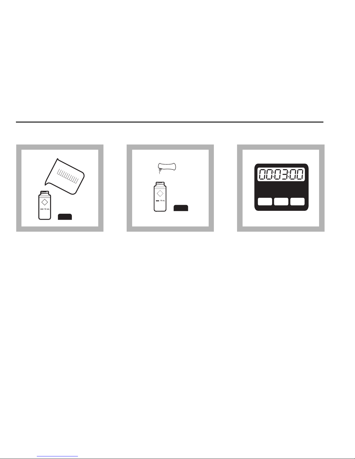
Using Powder Pillows
1.Fill a 10-mL cell to the
10 mL line with sample.
2.A dd the contents of one
Iron TPTZ Reagent Powder
Pillow to the cell (the
prepared sample). Cap and
shake for 30 seconds.
3.Wait at least 3 minutes
for full color development
before completing steps 4–
12.
HRS MIN SECHRS MIN SEC
Page 19
1—19
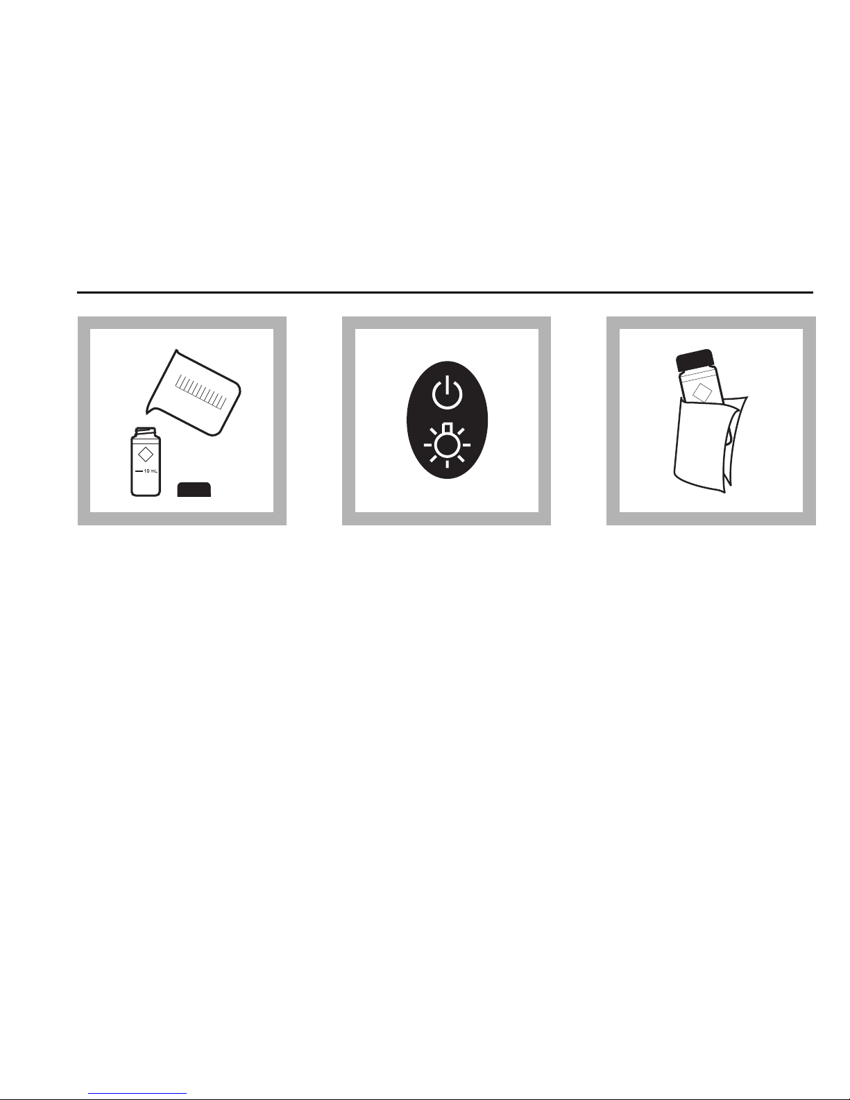
Iron, Total, continued
4.Fill a second sample cell
with 10 mL of sample (the
blank).
5.Pr ess the POWER key to
turn the meter on.
The arrow sh ould indicate
mg/L Fe.
Note:
See page 2—4 for
information on selecting the
correct range channel.
6.Wipe the sa mple cells
free of liquid or fingerprints.
Any liquid entering the
sample cell compartment
can cause damage to the
instrument.
Page 20
1—20
Iron, Total, continued
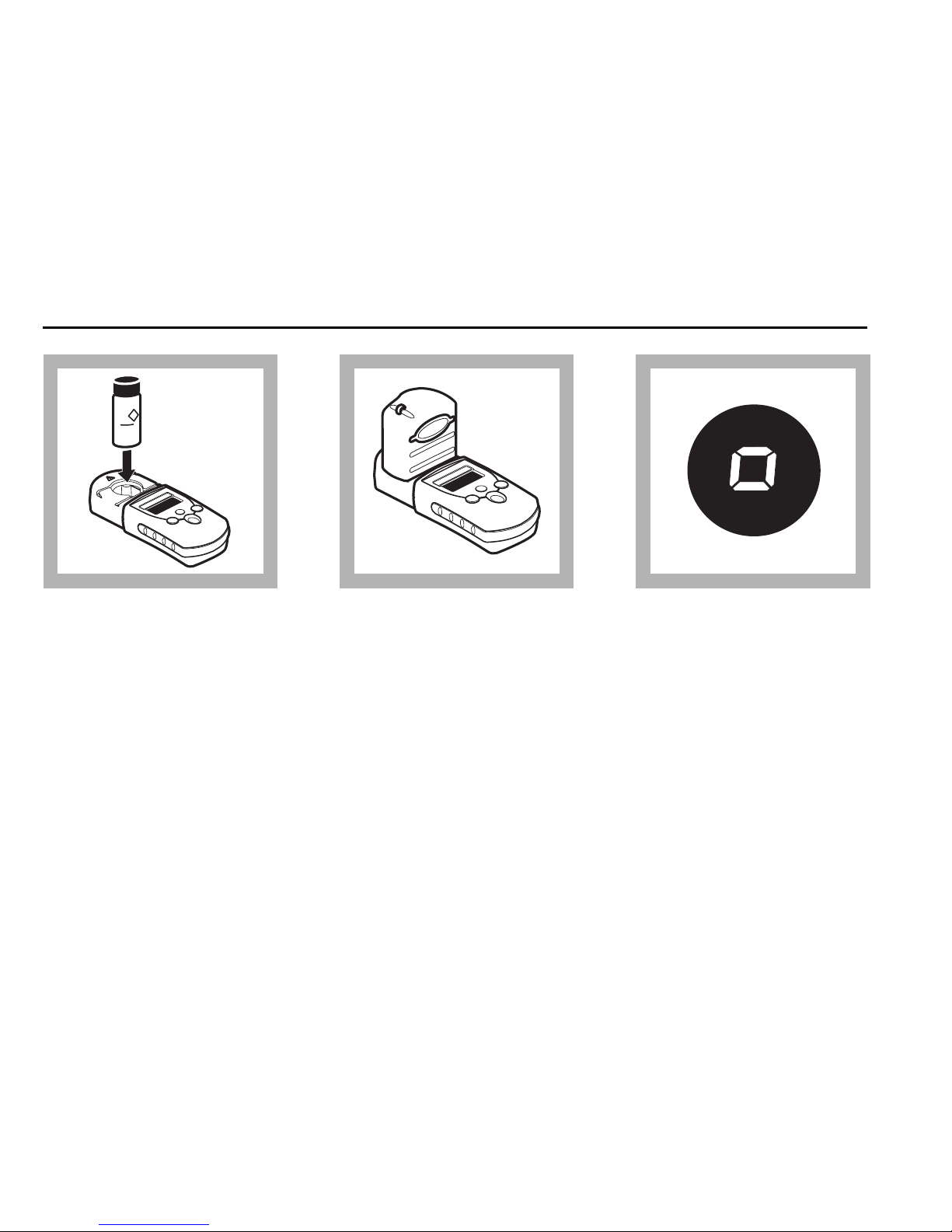
7.Place the blank in the
cell holder.
8.Cov er the blank with the
instrument cap.
9.Press ZERO/SCROLL.
The display will show
“- - - -” then “0.00”.
Remove the blank from the
cell holder.
Page 21
1—21
Iron, Total, continued
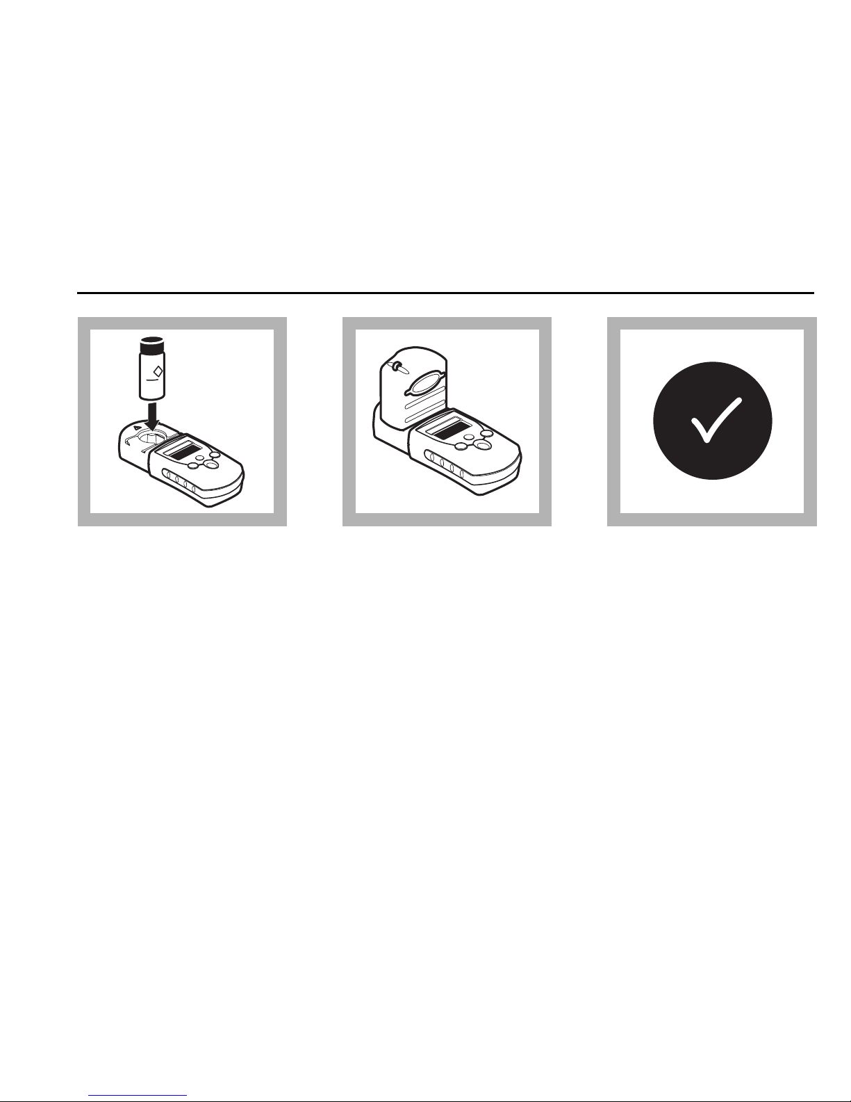
10. Place the prepared
sample in the cell holder.
11. Cover the sample cell
with the inst rument cap.
12.Press READ/ENTER.
The display will show
“- - - -” then “0.00”,
followed by results in mg/L
Iron.
Page 22
1—22
Iron, Total, continued
Using AccuVac® Ampuls
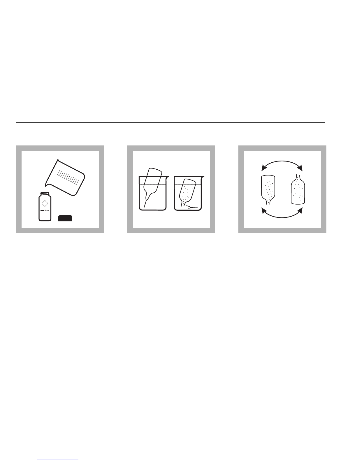
1.Fill a 10-mL cell to the
10 mL line with sample. Cap.
Collect at least 40 mL of
sample in a 50-mL beaker.
2.Fill an Iron TPTZ
Reagent AccuVac Ampul
with sample.
Note:
Keep the tip of the
ampule immersed until the
ampule fills completely.
3.Invert the ampule several
times to mix. Wipe off any
liquid or fingerprints.
Page 23

1—23
Iron, Total, continued
4.Wait at least 3 minutes
for full color development
before completing steps 5–
12.
5.Pr ess the POWER key to
turn the meter on.
The arrow sh ould indicate
mg/L Fe.
Note:
See page 2—4 for
information on selecting the
correct range channel.
6.Wipe the sa mple cells
free of liquid or fingerprints.
Any liquid entering the
sample cell compartment
can cause damage to the
instrument.
HRS MIN SECHRS MIN SEC
Page 24

1—24
Iron, Total, continued
7.Place the blank in the
cell holder.
8.Cov er the blank with the
instrument cap.
9.Press ZERO/SCROLL.
The display will show
“- - - -” then “0.00”.
Remove the blank from the
cell holder.
Page 25
1—25
Iron, Total, continued
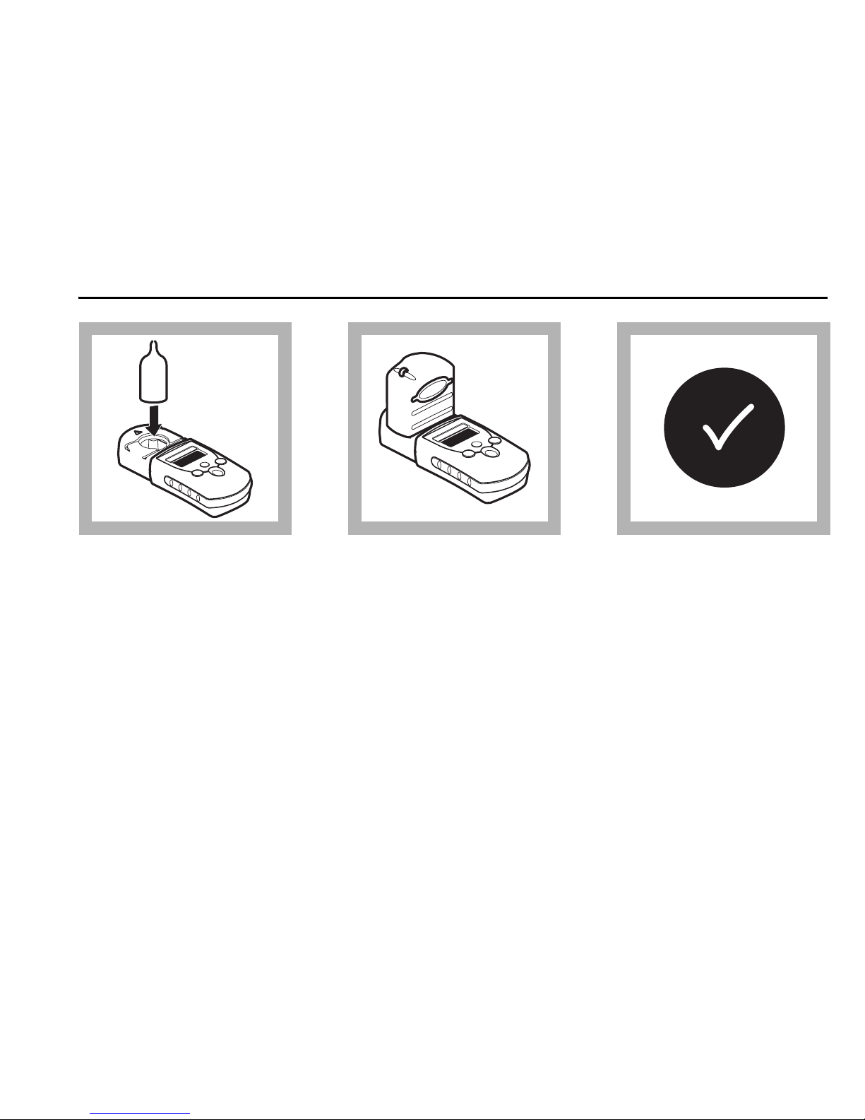
10. Place the prepared
sample in the cell holder.
11. Cover the sample cell
with the inst rument cap.
12.Press READ/ENTER.
The display will show
“- - - -” then “0.00”,
followed by results in mg/L
Iron.
Page 26

1—26
Iron, Total, continued
Sampling and Storage
Collect samples in acid-washed glass or plastic bottles. Adjust the sample pH to 2
or less with Nitric Acid (about 2 mL per L). Store samples preserved in this manner
up to 6 months at room temperature. If reporting only dissolved iron, filter the
sample immediately after collection and before addition of nitric acid.
Before testing, adjust the pH of the stored sample to between 3 and 4 with 5.0 N
Sodium Hydrox ide Standard Solution. Do n ot exceed pH 5 as iron may precipitate.
Accuracy Check
Standard Additions Method
1. Using a graduated cylinder, measure 25.0 mL of sample into each of three
50-mL beakers.
2. Snap the neck off an Iron Standard Solution Voluette™ Ampule, 25 mg/L Fe.
3. Use a TenSette
®
Pipet to add 0.1 , 0.2 , and 0.3 mL of standa rd, r espect ively, to
the three 50-mL beakers. Swirl to mix.
4. Analyze each standard addition sample as described in the procedure. The iron
concentration should increase by 0.1 mg/L for each 0.1 mL of standard added.
Page 27

1—27
Iron, Total, continued
Note:
For analysis with powder pillows, transfer only 10 mL of solution to 10-mL sample cells.
Standard Solutions Method
Use a 1.00 mg/L Iron Standard Solution in place of the sample. Perform the Total
Iron procedure. Multiparameter standards that simulate typical drinking water
concentrations without dilution are available to confirm tests. See Optional
Reagents on page 1—31.
Standard Calibration Adjust Method
To perform a standard calibration adjustment using the 1.0 mg/L iron standard or
using an alternate concentration, see Standard Calibrat ion Adjust on page 2—13.
Method Performance
Typical Precision (95% Confidence Interval):
1.00 ± 0.02 mg/L Fe
Estimated Detection Limit:
EDL = 0.01 mg/L Fe
Page 28

1—28
Iron, Total, continued
Interferences
A sample pH of less than 3 or greater than 4 after the addition of reagent ma y
inhibit color formation, caus e th e devel op e d col or to fad e qu ickl y or result in
turbidity. Before the addition of reagent, use a pH meter or pH paper to measure the
pH in the sample. A d just the sa mple pH to bet ween 3 and 8 by dr opwise ad ditio n
of an appropriate amount of iron-free acid or base such as 1.0 N Sulfuric Acid
Standard Solution or 1.0 N Sodium Hydroxide Standard Solution. Make a volume
correction if significant volumes of acid or base are used.
Interference tests were performed usi ng an iron concentra tion of 0.5 mg/L. When
interferences occurred, the color formation was inhibited or a precipitate formed.
Page 29

1—29
Iron, Total, continued
The following do not interfere with the test when present up to the levels listed:
Summary of Method
The TPTZ Iron Reagent forms a deep blue-purple color with ferrous iron. The
indicator is combined with a reducing agent which converts precipitated or
suspended iron, such as rust, to the ferrous state. The amount of ferric iron present
can be determined as the difference between the results of a ferrous iron test and
the concentration of total iron.
Element Interference level Element Interference level
Cadmium 4.0 mg/L Manganese 50.0 mg/L
Chromium
(3+)
0.25 mg/L Mercury 0.4 mg/L
Chromium
(6+)
1.2 mg/L Molybdenum 4.0 mg/L
Cobalt 0.05 mg/L Nickel 1.0 mg/L
Copper 0.6 mg/L Nitrite Ion 0.8 mg/L
Cyanide 2.8 mg/L
Page 30

1—30
Iron, Total, continued
Reagents and Apparatus
Required Reagents (Using Powder Pillows)
Description Quantity Pe r Test Unit Cat. No.
TPTZ Iron Reagent Powder Pillows,
10 mL size................................................2 pillows...............100/pkg ........26087-99
Required Reagents (Using AccuVac® Ampuls)
TPTZ Low Range Iron Reagent AccuVac® Ampuls
1 ampul .................25/pkg .........25100-25
Required Apparatus (Using AccuVac® Ampuls)
Description Quantity Pe r Test Unit Cat. No.
Beaker, 50 mL ................................................... 1 ...........................each..........500-41H
Page 31

1—31
Iron, Total, continued
Optional Reagents
Description Unit Cat. No.
Hydrochloric Acid Solution, 1:1 6.0 N........................................500 mL.........884-49
Iron Standard Solution, 1 mg/L Fe..............................................500 mL.........139-49
Iron Standard Solution Voluette™ Ampules,
25 mg/L Fe, 10 mL......................................................................16/pkg.....14253-10
Nitric Acid, ACS................................................................ ....... ......500 mL.........152-49
Nitric Acid Solution, 1:1...............................................................500 mL.......2540-49
Sodium Hydroxide Standard Solution, 1.0 N................... 100 mL MDB.......1045-32
Sodium Hydroxide Standard Solution, 5.0 N................... 100 mL MDB.......2450-32
Drinking Water Quality Control Standard, mixed parameter
(copper, iron, and manganese...................................................500 mL.....28337-49
Sulfuric Acid Standard Solution, 1.000 N........................ 100 mL MDB.......1270-32
Wate r, deionized.............................. .......................................................4 L.........272-56
Page 32

1—32
Iron, Total, continued
Optional Apparatus
Description Unit Cat. No.
AccuVac® Snapper...............................................................................each ....24052-00
Beaker, 50 mL ......................................................................................each ......500-41H
Cylinder, graduated 25 mL............................................................. ....each . ......1081-40
Dropper, graduated, 0.5 and 1.0 mL marks..................................10/pkg....21247-20
pH Indicator Paper, 1 to 11 pH............. ..................................5 rolls/pkg .........391-33
sens
ion™1 Basic Portable pH Meter, with electrode .....................each .....51700-10
Pipet Filler, safety bulb.......................................................................each .... 14651-00
Pipet, serological, 2 mL ......................................................................each ....... 532-36
Pipet TenSette
®
, 0.1 to 1.0 mL ...........................................................each .....19700-01
Pipet Tips, for 19700-01 TenSette
®
Pipet..................................... 50/pkg .... 21856-96
Replacement Parts
Batteries, alkaline..............................................................................4/pkg ....46743-00
Instrument Cap/light shield................... ........................................... each ....59548-00
Instruction Manual.......................................................................... ....each ....59577-8 8
Sample Cells, 10-mL, with caps.......................................................6/pkg ....24276-06
Page 33

1—33
Molybdenum, Molybdate, LR (0.02 to 3.00 mg/L Mo)
Method 8169
For boiler and cooling tower waters
Ternary Complex Method
Measuring Hints
• The results can be expressed as mg/L molybdate (MoO
4
2–
) or mg/L sodium
molybdate (NaMoO
4
) by multiplying the mg/L molybdenum (Mo6+) result by
1.67 or 2.15, respectively.
• Wipe sample cells with a soft, dry cloth before placing in the instrument.
• After adding reagent, a green color will develop if molybdenum is present in
the sample.
Note:
The Pocket Colorimeter™ II is designed to measure solutions contained in sample cells.
DO NOT
dip the meter in the sample or pour the sample directly into the cell holder.
Page 34

1—34
Molybdenum, Molybdate, LR, continued
1.Pr ess t he POWER key to
turn the meter on.
The arrow should indicate
the low range channel (LR).
Note:
See page 2—4 for
information on selecting the
correct range channel.
2.Fill a 25-mL mixing
graduated cylinder to the
20-mL mark with sample.
3.Ad d the cont ents of o ne
Molybdenum 1 Reagent
Powder Pillow to the
cylinder. Stopper the
cylinder and inv ert or gently
shake until all particles are
dissolved.
Page 35

1—35
Molybdenum, Molybdate, LR, continued
4.Split the sample by filling
two 10-mL sample cells to
the 10-m L mark. Cap one of
the cells, this is the blank.
Note:
Exactly 10 mL is not
critical for the blank. Make
sure the other cell contains
10 mL.
5.Using the calibrated
dropper, add 0.5 mL of
Molybdenum 2 to the
sample in the uncapped 10mL cell. Cap the cell and
swirl to mix. Wait two
minutes for full color
development.
6.Wipe the sa mple cells
free of liquid. Any liquid
entering the sample cell
compartment can cause
damage to the instrument.
Page 36

1—36
Molybdenum, Molybdate, LR, continued
7.Place the blank in the
cell holder.
8.Cov er the blank with the
instrument cap.
9.Press ZERO/SCROLL.
The display will show
“- - - -” then “0.00”.
Remove the blank from the
cell holder.
Page 37

1—37
Molybdenum, Molybdate, LR, continued
10. Place the prepared
sample in the cell holder.
11. Cover the sample cell
with the inst rument cap.
12.Press READ/ENTER.
The display will show
“- - - -” then “0.00”,
followed by results in mg/L
Molybdenum.
Page 38

1—38
Molybdenum, Molybdate, LR, continued
Sampling and Storage
See Sampling and Storage on pa ge 1—44.
Accuracy Check
See Accuracy Check on page 1—44.
Interferences
See Interferences on page 1—46.
Summary of Method
See Summary of Method on page 1—49.
Replacement Parts
Replacement Parts on page 1—51
Page 39

1—39
Molybdenum, Molybdate, HR (0.1 to 12.0 mg/L Mo)
Method 8169
For boiler and cooling tower waters
Ternary Complex Method
Measuring Hints
• The results can be expressed as mg/L molybdate (MoO
4
2–
) or mg/L sodium
molybdate (NaMoO
4
) by multiplying the mg/L molybdenum (Mo6+) result by
1.67 or 2.15, respectively.
• Wipe sample cells with a soft, dry cloth before placing in the instrument.
• After adding reagent, a green color will develop if molybdenum is present in
the sample.
Note:
The Pocket Colorimeter™ II is designed to measure solutions contained in sample cells.
DO NOT
dip the meter in the sample or pour the sample directly into the cell holder.
Page 40

1—40
Molybdenum, Molybdate, HR, continued
1.Pr ess t he POWER key to
turn the meter on.
The arrow should indicate
the high range channel (HR).
Note:
See page 2—4 for
information on selecting the
correct range channel.
2.Fill a 25-mL mixing
graduated cylinder to the
5-mL mark with sample.
3.Dilute to the 20-mL
mark with deionized water.
Page 41

1—41
Molybdenum, Molybdate, HR, continued
4.A dd the contents of one
Molybdenum 1 Reagent
Powder Pillow to the
cylinder. Stopper the
cylinder and invert or gently
shake until all particles are
dissolved.
5.Split the sample by filling
two 10-mL sample cells to
the 10-m L mark. Cap one of
the cells, this is the blank.
6.Using the calibrated
dropper, add 0.5 mL of
Molybdenum 2 to the
sample in the uncapped
10-mL cell. Cap the cell and
swirl to mix. Wait two
minutes for full color
development.
Page 42

1—42
Molybdenum, Molybdate, HR, continued
7.Wipe the sample cells
free of liquid. Any liquid
entering the sample cell
compartment can cause
damage to the instrument.
8.Place the blank in the
cell holder.
9.Co ver the blank with the
instrument cap.
Page 43

1—43
Molybdenum, Molybdate, HR, continued
10. Press ZERO/SCROLL.
The display will show
“- - -” then “0.0”.
Remove the blank fro m the
cell holder.
11. Pla ce the prepared
sample in the cell holder.
Cover the sample cell with
the instrument cap.
12.Press READ/ENTER.
The display will show
“- - - -” then “0.00”,
followed by results in mg/L
Molybdenum.
Page 44

1—44
Molybdenum, Molybdate, HR, continued
Sampling and Storage
Collect samples in glass or plastic bottles.
Accuracy Check
Standard Additions Method
1. Snap the neck off a Molybdenum Sta ndard Solution as Mo 75 mg/L Voluette®
ampule.
2. Use a TenSette® Pipet to add 0.1 mL, 0.2 mL, and 0.3 mL of standard,
respectively, to three 20-mL samples. Mix each thorough ly.
3. Analyze each sample as described above. The molybdenum concentration
should increase appro xim ately 0. 38 mg/L for the low ra nge and 1.6 mg/L for
the high range for each 0.1 mL of standard added.
Standard Solutions Method
For the Low Range, use Class A glassware to prepare a 2.00-mg/L molybdenum
standard solution by pipetting 10 .00 mL of Molybdenum Standard Solution, 1 0.00mg/L, into a 50-mL volumetric flask. Dilute to the mark with deionized water. For
the High Range, use the 10.0 mg/L standard directly. Dilute to the mark with
deionized water. Prepare this solution daily. Perform the molybdenum procedure.
Page 45

1—45
Molybdenum, Molybdate, HR, continued
Method Performance
Typical Precision (95% Confidence Interval):
2.00 ± 0.02 mg/L Mo (LR)
10.0 ± 0.1m g/L Mo (HR)
Estimated Detection Limit:
EDL = 0.02 mg/L Mo LR
EDL = 0.1 mg/L Mo HR
Standard Calibration Adjust Method
To perform a standard calibration adjustment using the 2.00 and 1 0.0 molybdenum
standard or using an al ternate concentration, see Standard Calibration Adjust on
page 2—13.
Page 46

1—46
Molybdenum, Molybdate, HR, continued
Interferences
Interference studies were conducted by preparing a molybdenum standard solution
(2 mg/L Mo
6+
) as well as a solution of the potential interfering ion. When the
standard solution concentration changed by ± 5% with a given ion concentration,
the ion was considered an interference.
Large interferences are caused by some biocides common to cooling water tower
samples. Hach recommends testing the procedure on molybdenum standards in the
presence of the specific biocides in use to determine the feasibility of the ternary
complex chemistry.
.
Negative Interference:
Ion
Interferes at
(mg/L):
Ion
Interferes at
(mg/L):
Acrylates 790 Diethanoldithiocarba-mate 32
Alum 7 EDTA 1500
Aluminum 2 Ethylene Glycol 2%
(by volume)
Page 47

1—47
Molybdenum, Molybdate, HR, continued
AMP (Phosphonate) 15 Iron 200
Bicarbonate 5650 Lignin Sulfonate 105
Bisulfite 3300 Nitrite 350
1
Borate 5250 Orthophosphate 4500
Chloride 1400 Phosphonohydroxy-
acetic acid
32
Chromium (Cr
6+
) 4.51 Sulfite 6500
Copper 98
1
Read the molybdenum concentration immediately after the 2-minute reaction period
has ended.
Negative Interference: (Continued)
Ion
Interferes at
(mg/L):
Ion
Interferes at
(mg/L):
Page 48

1—48
Molybdenum, Molybdate, HR, continued
The presence of the phosphonate HEDP at concentrations up to 30 mg/L will
increase the apparent molybdenum concentration reading by approximately 10%
Positive Interference:
Ion Highest Concentration Tested (mg/L):
Benzotriazole 210
Carbonate 1325
Silica 600
No Interference:
Ion
Highest
Concentration
Tested (mg/L):
Ion
Highest
Concentration
Tested (mg/L):
Bisulfate 9600 Nickel 250
Calcium 720 PBTC (phosphonate) 500
Chlorine 7.5 Sulfate 12800
Magnesium 8000 Zinc 400
Manganese 1600
Page 49

1—49
Molybdenum, Molybdate, HR, continued
(positive interference). For these samples, multiply the value obtained in the final
step of the procedure by 0.9 to obtain the actual molybd enum concentration.
As the concentration of HEDP increases above 30 mg/L, a decrease in the
molybdenum concentration reading occurs (negative interference).
Highly buffered samples or extreme sample pH may exceed the buffering capacity
of the reagent and require sample pretreatment. Adjust the sample pH to between
3 and 5 by using a pH meter or pH paper and add, drop-wise, an appropriate
amount of acid or base such as 1.0 N Sulfuric Acid Standard Solution or 1.0 N
Sodium Hydroxide Solution. If significant volumes of acid or base are used, a
volume correction should be made. Divide the total volume (sample + acid + base)
by the original volume and multiply th e test result by this factor.
After several samples have been analyzed, the sample cells may exhibit a slightly
blue buildup. Eliminate buil du p wit h a ri nse of Hydroch loric Acid Solution, 1:1.
Summary of Method
Molybdate is determined with the ternary complex method by the reaction of
molybdate molybdenum with an indicator and a sensitizing agent yielding a stable
blue complex. While molybdate (MoO
4
2–
) is the actual chemical species involved
in the chemistry, the instrument displays the result as molybd enum, Mo.
Page 50

1—50
Molybdenum, Molybdate, HR, continued
Required Reagents
Description Unit Cat. No.
Molybdenum, Molybdate Reagent Set,
20-mL sample........................................................................... 100 tests ....24494-00
Includes:
Molybdenum 1 Reagent Powder Pillow, 100/pkg
Molybdenum 2 Reagent Solution, 50 mL
Optional Reagents
Hydrochloric Acid Solution, 1:1, 6.0 N...................................... 500 mL ........ 884-49
Molybdenum Standard Solution, 10 mg/L as Mo......................100 mL .... 14187-42
Sodium Hydroxide Standard Solution, 1.000 N...............100 mL MDB .......1045-32
Optional Reagents, continued
Description Unit Cat. No.
Sulfuric Acid Standard Solution, 1.000 N.........................100 mL MDB .......1270-32
Wate r, deionized....................................................................... ....... ......4 L ........ 272-56
Page 51

1—51
Molybdenum, Molybdate, HR, continued
Optional Apparatus
Cylinder, mixing, 25-mL....................... ....... ......................................each.....20886-40
Funnel, poly, 65-mm..........................................................................each.......1083-67
Filter paper, folded, 12.5-cm.......................................................pkg/100.......1894-57
Flask, volumetric, 50-mL...................................................................each. ....145 74-41
Pipet, TenSette
®
, 0.1 to 1.0-mL .........................................................each.....19700-01
Pipet, volumetric, 10-mL, Class A ....................................................each.....14515-38
Pipet Filler, safety bulb......................................................................each.....14651-00
Pipet Tips, TenSette
®
(for 19700-01)........................ ....... ..............pkg/50.....21856-96
Replacement Parts
Batteries, alkaline, AAA...................................................................pkg/4.....46743-00
Instrument Cap/light shield............................................. ....... ....... ....each.....59548-00
Instruction Manual.............................................................................each .....59577-88
Sample Cells, 10-mL, with caps......................................................pkg/6.....2427 6-0 6
Page 52

1—52
Page 53

1—53
Ozone (0.01 to 0.25 mg/L O
3
—LR and 0.01 to 0.75 mg/L O3—MR)
For water
Method 83 11
Indigo Method (Using AccuVac® Ampuls)*
Measuring Hints
• Ozone sample cannot be stored , th ey must be a nalyzed im media tely to a void
ozone loss.
• For best results, clean collection containers after each use.
• If the ozone concentration exceeds the upper limit of the test, the color will not
develop properly. The display will show “overrange” (flashing) when the
concentration is exceeded.
• If the reading is over 0.25 mg/L us ing the low range, repeat the test using
mid-range ampules and the mid-range of the instrument. If the concentration
is over 0.75 mg/L, dilute the sample with high quality water that is ozone-free
and repeat the test. Multiply the result by the appropriate dilution factor. Some
loss of ozone may occur during dilution.
Note:
The Pocket Colorimeter™ II is designed to measure solutions contained in sample cells.
DO NOT
dip the meter in the sample or pour the sample directly into the cell holder.
* Adapted from Standard Methods for the Examination of Water and Wastewater.
Page 54

1—54
Ozone, continued
1.Pr ess t he POWER key to
turn the meter on.
The arrow should indicate
LR when using the Low
Range ampules or should
indicate MR when using the
mid-range ampules .
Note:
See page 2—4 for
information on selecting the
correct range channel.
2.Gently collect at least 40
mL of sample in a 50-mL
beaker.
Note:
Samples must be
analyzed immediately and
cannot be preserved for later
analysis.
3.Collect at least 40 mL of
ozone-free water (blank) in
another 50-mL beaker.
Note:
Ozone-free water used
for the blank may be
deionized or tap water if
samples do not contain
significant color or turbidity.
Page 55

1—55
Ozone, continued
4.Fill one Indigo Ozone
Reagent AccuVa c Ampul of
the appropriate range with
the sample and another
ampule with the blank.
Keep the tip immersed while
the ampule fills completely.
5.Gently but quickly in vert
both ampules sev eral times
to mix. Wipe off any liquid
or fingerprints.
Note:
Do not shake the
ampules. Shaking will result
in a loss of ozone.
Note:
Part of the blue color
will be bleached if ozone is
present.
6.Place the blank in the
cell holder.
Page 56

1—56
Ozone, continued
7.Cov er the blank with the
instrument cap.
8.Press ZERO/SCROLL.
The display will show
“- - - -” then “0.00”.
Remove the blank fro m the
cell holder.
9.Place the pr epared
sample into the cell holder.
Page 57

1—57
Ozone, continued
10. Cover the sample cell
with the instrument ca p.
11. Press READ/ENTER.
The display will show
“- - - -” then “0.00”,
followed by results in mg/L
Ozone (O
3
).
Page 58

1—58
Ozone, continued
Sampling and Storage
The main consideration when collecting a sample is preventing the escape of ozone
from the sample. The sample should be collected gently and analyzed immediately.
W arming the sample or dist urbing the sample by stirring or shaking will result in ozone
loss. After collecting the sample, do not transfer it from one container to another unless
absolutely necessary.
Stability of Indigo Reagent
Indigo is light-sensitive. Therefore, the AccuVac Ampuls should be kept in the dark at
all times. However, the indigo solution decomposes slowly under room light after filling
with sample. The blank ampule can be used for multiple measurements during the
same day.
Accuracy Check
Standard solutions for ozone are difficult and time-consuming to prepare. Errors can
occur if proper attention to details is not taken while preparing the standards. The
manufacturer prepares the calibration curve under rigorous analytical laboratory
conditions and recommends using the factory calibration.
Page 59

1—59
Ozone, continued
A user calibration or a user-prepared ozone standard may be required by a
regulatory official or agency . Two options are available on the Pock et Colorimeter
II to meet this requirement.
An ozone standard may be prepared and used to validate th e ca lib ra tion curve
using the Standard Calibr ation A djust feature (s ee Standard Calibration Adjust on
page 2—13). The concentration of the prepared standard must be determined with
an alternate instrument such as a spectrophotometer, colorimeter, amperometric
titration or by an alternate method. The concentration of the ozon e standard for
the Low Range procedure must be between 0.1 0 and 0.20 mg/L ozone a nd between
0.30 and 0.70 mg/L ozone for the mid-range procedure.
In addition, a user-generated calibration curve can be made and programmed into
the Pocket Colorimeter II. See User-Entered Calibration on page 2—15.
Specê Secondary Standards for Instrument Verification
(Mid-range Only)
Note:
Due to improvements in the optical system of the Pocket Colorimeter™ II, the tolerance
ranges and values on the Certificate of Analysis of previously purchased Spec
√
standards
may no longer be valid. Obtain a new set of standards, or use the Pocket Colorimeter II to
assign new values to existing standards.
Page 60

1—60
Ozone, continued
Spec√ Secondary Standards are available to quickly check the repeatability of the
Pocket Colorimeter II instrument. After in it ial m easu rem en ts for the Spec√
standards are collected, the standards can be re-checked as often as desired to
ensure the instrument is working consistently.
The standards do not ensure reagent quality nor do they ensure the accuracy of the
test results. Analysis of real standard solutions using the kit reagents is required to
verify the accuracy of the entire Pocket Colorimeter system. The Spec√ Standards
should NEVER be used to calibrate the instrument. The certificate of analysis lists
the expected value and tolerance for each Spec√ Standard.
Note:
Before proceeding, make sure the instrument is in the mid-range (MR). See Switching
Ranges on page 2—4.
Using the Spec√ Standards
1. Place STD 1 into the cell holder with the alignment mark facing the keypad.
Tightly cover the cell with the in st rum ent cap.
2. Press
ZERO. The display will show “0.00”.
3. Place the blank cell into the cell holder. Tightly cover the cell with the
instrument cap.
4. Press
READ/ENTER. Record the concentration measurement.
Page 61

1—61
Ozone, continued
5. Repeat steps 1– 4 with cells labeled STD 2 and STD 3.
6. Compare these measurements with previous measurements to verify the
instrument is performing consistently. (If these are the first measurements,
record them for comparison with later meas urements.)
Note:
If the instrument is user-calibrated, initial standard measurements of the Spec √
Standards will need to be performed again for the user calibration.
Summary of Method
The reagent formulation adjusts the sample pH to 2.5 after the ampule has filled.
The indigo reagent reacts immediately and quantitatively with ozone.
The blue color of indigo is bleached in proportion to the amount of ozone present
in the sample. Other reagents in the formulation prevent chlorine interference. No
transfer of sample is necessary in the procedure. Therefore, ozone loss due to
sampling is eliminated.
Page 62

1—62
Ozone, continued
Reagents and Apparatus
Required Reagents
Select one or both based on sample range:
Description Unit Cat. No.
Low Range Ozone AccuVac® Ampuls, 0 to 0.25 mg/L............... 25/pkg .... 25160-25
Mid-Range Ozone AccuVac
®
Ampuls, 0 to 0.75 mg/L............... 25/pkg .....25170-25
Required Apparatus (Using AccuVac® Ampuls)
Beaker, 50 mL ......................................................................................each ......500-41H
Optional Reagents
Spec√ Secondary Standards, Ozone, mid-range.......................... ....... ....... ... 2 7080-00
Replacement Parts
Batteries, alkaline..............................................................................4/pkg ....46743-00
Instrument Cap/light shield................... .............................................each .... 46704-00
Instruction Manual.......................................................................... ....each ....59577-8 8
Page 63

1—63
Zinc (0.02 to 3.00 mg/L Zn)
For water and wastewater
Method 8009
Zincon Method* USEPA Approved for wastewater (digestion required)**
Measuring Hints
Caution! The reagent used in step 3 contains cyanide and is very poisonous
if taken internally or if the vapors are inhaled. Do not add to a sample with
a pH of less than 4. See Sampling and Storage for pH adjustment.
• Testing for non-reporting purposes generally does not require sample
digestion. However, if the sample contains particulate matter, digestion is
required for total zinc measurement.
• Use only glass stoppered cylinders in the procedure.
• Wipe sample cells with a soft, dry cloth before placing in the instrument.
Note:
The Pocket Colorimeter™ II is designed to measure solutions contained in sample cells.
DO NOT
dip the meter in the sample or pour the sample directly into the cell holder.
* Adapted from Standard Methods for the Examination of Water and Wastewater, 15th ed.
244 (1980).
** Federal Register, 45(105) 36 1 66 (May 29, 198 0). See the Hach Water Analysis Handbook
for further information concerning digestions.
Page 64

1—64
Zinc, continued
1.Pr ess t he POWER key to
turn the meter on.
The arrow should indicate
mg/L Zn.
Note:
See page 2—4 for
information on selecting the
correct channel.
2.Fill a 25-mL mixing
graduated cylinder to the
20-mL mark with sample.
3.Ad d the cont ents of o ne
ZincoVer
®
5 Reagent Powder
Pillow to the cylinder.
Stopper the cylinder and
invert or gently shake until
all particles are dissolved.
Page 65

1—65
Zinc, continued
4.Measure 10 mL of the
solution into a 10-mL
sample cell (the blank)
leaving exactly 1 0 mL in the
mixing cylinder.
5.Us e the calibrated
dropper to add 0.5 mL of
cyclohex a none to the
sample remaining in the
mixing cylinder. Stopper and
shake for 30 seconds. Wait
three minutes but no longer
than 15 minutes for full
color development before
performing step 6.
6.Fill a clean 10-mL
sample cell to the 10-mL
mark with the solution in
the mixing cylinder. This i s
the prepared sample.
Page 66

1—66
Zinc, continued
7.Place the blank in the
cell holder.
8.Cov er the blank with the
instrument cap.
9.Press ZERO/SCROLL.
The display will show
“- - - -” then “0.00”.
Remove the blank from the
cell holder.
Page 67

1—67
Zinc, continued
10. Place the prepared
sample in the cell holder.
11. Cover the sample cell
with the inst rument cap.
12.Press READ/ENTER.
The display will show
“- - - -” then “0.00”,
followed by the results in
mg/L Zn.
Page 68

1—68
Zinc, continued
Sampling and Storage
Collect sample in acid-washed plastic or glass bottles. For storage, adju st the pH to 2 or
less with nitric acid (about 2 mL per liter). The preserved samples can be stored for up
to six months at room temperature. Adjust the pH to between 4 to 5 with 5.0 N Sodium
Hydroxide bef ore analysis. Never add the reagent to samples with p H less than 4. Do not
exceed pH 5, as zinc may be lost as a precipitate.
Accuracy Check
Standard Additions Method
1. Snap the neck off a Zinc Standard Solution Voluette® Ampule, 25 mg/L.
2. Use a TenSette
®
Pipet to add 0.1 mL, 0.2 mL and 0.3 mL of standard, respectively,
to three 25-mL samples. Mix each thoroughly.
3. Analyze 20 mL of each sample as described above. The zinc concentration should
increase 0.1 mg/L for each 0.1 mL of standard added.
Page 69

1—69
Zinc, continued
Standard Solution Method
Prepare a 2.00 mg/L zinc standard by diluting 2.00 mL of Zinc Standard Solution,
100 mg/L as Zinc, to 100 mL. Use volumetric pipets and flasks. Perform the
procedure as described above.
Method Performance
Typical Precision (95% Confidence Interval):
2.00 ± 0.08 mg/L Zn
Estimated Detection Limit:
EDL = 0.02 mg/L Zn
Standard Calibration Adjust Method
To p erform a standard calibration adjust ment using the 2.00 mg/L zinc standard, or
to use an alternative concentration, see Standard Calibration A djust on page 2—13.
Page 70

1—70
Zinc, continued
Interferences
The following may interfere when present in concentrations exceeding those
listed:
Large amounts of organic material may interfere. Digest the sample to eliminate
this interference. Highly buffered samples or extreme sample pH may exceed the
buffering capacity of the reagents and require sample pretreatment.
Waste Management
ZincoV er 5 reagent contains potassium cyanide. Cyanide solutions are regulated as
hazardous wastes by the Federal RCRA. Cyanide should be collected for disposal as
a reactive (D003) waste. Be sure that cyanide solutions are stored in a caustic
solution with pH >11 to prevent release of hydrogen cyanide gas.
Aluminum 6 mg/L Iron (ferric) 7 mg/L
Cadmium 0.5 mg/L Manganese 5 mg/L
Copper 5 mg/L Nickel 5 mg/L
Page 71

1—71
Zinc, continued
Summary of Method
Zinc and other metals in the sample are complexed with cyanide. The addition of
cyclohexanone causes a selective release of zinc. The zinc then reacts with
2-carboxy-2'-hydroxy-5'-sulfoformazyl benzene (Zincon) indicator to form a
blue-colored species. The blue color is masked by the brown color from the
excess indicator. The intensity of the blue color is proportional to the amount of
zinc present.
Reagents and Apparatus
Required Reagents
Description Cat. No.
Zinc Reagent Set (100 tests)............................................................................24293-00
Includes:
(1) Cyclohexanone, 100 mL MDB
(1) ZincoVer® 5 Reagent Powder Pillows, 100/pkg
Required Apparatus
Cylinder, graduated mixing, 25-mL........... ....... ...... .........................each.....2088 6-4 0
Page 72

1—72
Zinc, continued
Optional Reagents
Description Cat. No.
Hydrochloric Acid, 6.0 N.............................................................. 50 0 mL ........ 884-49
Nitric Acid, 1:1.............................................................................. 500 mL ...... 2540-49
Sodium Hydroxide Standard Solution, 5.0 N....................59 mL SCDB ...... 2450-26
Wate r, deionized....................................................................... ....... ......4 L ........ 272-56
Zinc Standard Solution, 100 mg/L...............................................100 mL ......2378-42
pH Indicator paper, 1-11 pH ........................ ....... ....................5 rolls/pkg .........391-33
Zinc Standard Solution Voluette
®
Ampules,
25 mg/L as Zn, 10-mL................................................................ 16/pkg....14246-10
Optional Apparatus
Flask, volumetric, 100-mL................................................ ....... ...........each ....14574-42
Pipet, volumetric, 2.00 mL.................................................................each .... 14515-36
Pipet Filler, safety bulb.......................................................................each .... 14651-00
Replacement Parts
Batteries, alkaline..............................................................................4/pkg ....46743-00
Instrument Cap/light shield................... .............................................each ....59548-00
Instruction Manual.......................................................................... ....each . ...59577-88
Sample Cells, 10-mL, with caps.......................................................6/pkg ....24276-06
Page 73

2—1
Section 2
Instrument Manual
Page 74

2—2
Page 75

2—3
Instrument Operation
Key Functions
Key Description Function
POWER On/Off/Backlight
To turn on the backlight, turn on the instrument, then
press and hold the power key until the backlight turns
on. Press and hold again to turn off the backlight. This
key functions the same in all instrument modes and
ranges.
ZERO/SCROLL In measurement mode, sets the instrument to zero.
In menu mode, scrolls through menu options. Also
scrolls numbers when entering or editing a value.
READ/ENTER In measurement mode, initiates sample measurement.
In menu mode, selects a menu option. When entering
numbers, moves one space to the right and executes
the function when the entry is complete.
Page 76

2—4
Instrument Operation, continued
Menu Selections
Press the MENU key to access the menu selections.
Switching Ranges
1. Press the MENU key. The display will sho w “SE L”. A flashing arrow indicates
the current range.
2. Press the
READ/ENTER key to toggle between ranges.
3. Press
MENU again to accept and exit back to the measurement screen.
Setting the Time
1. Press the MENU key, then press the ZERO/SCROLL ke y un til th e di spla y shows
a time in the “00:00” format.
MENU Enter/Exit the menu mode
Press and hold for approximately 5 seconds to enter
user-entered method mode.
Key Description Function
Page 77

2—5
Instrument Operation, continued
2. Press READ/ENTER. The digit to be edited will flash.
3. Use the
ZERO/SCROLL key to change the entry, then press READ/ENTER to
accept and advance to the next digit. The time is entered in 24-hour format.
Recalling Stored Measurements
1. Press the MENU key, then press the ZERO/SCROLL key until the display shows
RCL. The instrument automatically stores the last 10 measurements.
2. In RCL, press
READ/ENTER to recall the stored measurements, beginning with
the most recent measurement taken. The meter stores the measurement
number as 0 1 (most recent) through 1 0 (oldest), the time the measurement was
taken, and the measurement value. The
ZERO/SCROLL key allows for selection
of a specific measurement by number. The
READ/ENTER key scrolls thro ugh all
stored data points.
Page 78

2—6
Instrument Operation, continued
Battery Installation
Figure 1 on page 2—7 provides an exp lod ed vi ew of battery installation.
1. Unhook the latch and remove the bat tery co mpartment cover. The polarities
are shown on the battery holder.
2. Place the four batteries provided with the instrument in the holder as indicated
and replace the battery compartment cover. The display will show the software
version number (e.g., “P 1.6”) after correct battery installation.
When replacing discharged batteries, always replace the complete set of four
alkaline batteries. Rechargeable batteries are not recommended and cannot be
recharged in the instrument.
Note:
The Low Battery icon will appear on the display when the batteries have 10 % battery life
remaining. The battery icon will flash when the batteries are too low to complete
measurements. See Instrument Keys and Display on page 1—13.
Page 79

2—7
Instrument Operation, continued
Figure 1 Battery Installation
Page 80

2—8
Page 81

2—9
Error Codes
When the instrument canno t perfo r m th e funct io n in it iat ed by the operator, an
error message will appear in the display. Refer to the appropriate message
information below to determine what the problem is and how it can be corrected.
Resolve error messages in the order that they appear on the display. Service Centers
are listed in page 2—37.
Error Messages
1. E-0 No Zero (User mode)
Error occurs when trying to read a standard in the user calibration mode
before setting the meter to zero.
• Zero the instrument on an appropriate blank.
2. E-1 Ambient Light Er ro r
There is too much light present to take a valid measurement.
• Verify instrument cap is correctly seated.
• If the problem persists, contact a Service Center (page 2—37).
Page 82

2—10
Error Codes, continued
3. E-2 LED Error
The LED (light source) is out of regulation.
• Replace batteries.
• Verify LED lights up (inside the cell holder) when the READ/ENTER or
ZERO/SCROLL key is pressed.
• If the problem persists, contact a Service Center (page 2—37).
Note: When an E-1 or E-2 error occurs on a measurement, the display will show “_.__”. (The
decimal place is determined by the chemistry.) If the E-1 or E-2 error occurs while
zeroing the meter , the meter will require the user to re-zero.
4. E-3 Standard Adjust Error
The value obtained on the prepared standard exceeds the adjustment limits
allowed for the standard concentration, or the concentration of the standard is
outside the concentration range allowed for standard calibration adjust.
• Prepare the standard and rerun according to the procedure.
• Prepare a standard at or near the recommended concentrations given in the
procedure.
• Verify that the concentration of the standard ha s been entered correctly.
Page 83

2—11
Error Codes, continued
• If the problem persists, contact a Service Center (page 2—37).
5. E-6 Abs Error (User mode )
Indicates that the absorbance value is invalid, or indicates an attempt to make
a curve with less than two points.
• Enter or measure the absorbance value again.
• If the problem persists, contact a Service Center (page 2—37).
6. E-7 Standard Value Error (User mode)
Standard concentratio n is equ al to another standard concentr ation that is
already entered.
• Enter the correct standard concentration.
• If the problem persists, contact a Service Center (page 2—37).
7. E-9 Flash Error
The meter is unable to save data.
• If the problem persists, contact a Service Center (page 2—37).
Page 84

2—12
Error Codes, continued
8. Underrange—flashing number below stated test range
• Verify instrument cap is correctly seated.
• Check zero by measuring a blank. If error recurs, re-zero the instrument.
• If the problem persists, contact a Service Center (page 2—37).
Note: See Maximum/Minimum Displayed Value on page 2—26 for more information.
9. Overrange—flashing number above stated test range
Note: Flashing value will be 10% over the upper test limit.
• Check for light blockage.
• Dilute and retest sample.
Note: See Maximum/Minimum Displayed Value on page 2—26 for more information.
Page 85

2—13
Standard Calibration Adjust
The Pocket Colorimeter™ II instrument is factory-calibrated and ready for use
without user calibration. Use of the factory calibration is recommended unless the
user is required to generate a calibration. The Standard Calibration Adjust can be
used to meet regulatory requirements.
This feature allows the factory default calibration curve to be adjusted with a
known standard. Use the standard described in the procedure.
1. Place a blank in the meter (in measurem ent mo de). Press
ZERO/SCROLL.
2. Place the reacted standard in the meter. Press
READ/ENTER.
3. Press
MENU, then press ZERO/SCROLL until the display shows “SCA”.
4. Press
READ/ENTER to display the standa rd calibration adjust valu e.
5. Press
READ/ENTER to adjust the curve to the displayed value. The meter will
return to the measurement mode and the Calibration Adjusted icon will appear
in the display window .
If an alternate concentration is used, or if a standard concentration is not given:
6. Repeat steps 1–4.
Page 86

2—14
Standard Calibration Adjust, continued
7. Press ZERO/SCROLL to access the Edit function, then press READ/ENTER to
begin editing. The digit to be edited will flash. Use the
ZERO/SCROLL key to
change the entry, then press
READ/ENTER to accept and advance to the
next digit.
When the last digit is entered, press
READ/ENTER and the meter will adjust the
curve to the value entered. The meter will return to measurement mode and the
Calibration Adjusted icon will appear in the display window.
To turn off Standard Calibration Adjust (SCA):
1. Press
MENU.
2. Press
ZERO/SCROLL until “SCA” app e ars in the displa y.
3. Press
READ/ENTER, then press ZERO/SCROLL until “Off” appears in the display.
4. Press
READ/ENTER to turn off SCA.
Note: Perform another standard calibration adjust to turn SCA on again.
Note: For meters with factory-calibrated ranges or methods, Standard Calibration Adjust
(SCA) will be disabled when a user-entered method is programmed into the meter. To
turn SCA back on, restore the meter to factory default calibration. See Retrieving the
Factory Calibration on page 2—25.
Page 87

2—15
User-Entered Calibration
Overview
The Pock et Colorimeter™ II will accept a user-prepared calibration curve. The curve
can extend from 0 to 2.5 absorbance. A user-prepared calibration curve may be
entered into any channel that does not contain a factory-progr ammed curve. These
channels are labeled “abs” on instruments having a single factory calibration or
are labeled “1” and “2” on the uncalibrated single wavelength instruments. Any
chemistry that can be run at the instrument wavelength may be user-entered in
these channels.
Using prepared standard solutions that cover the range of interest, th e mete r
generates a calibration curve by calculatin g th e stra igh t-l in e segments between
each standard entered. A calibration curve may be entered using the keypad.
Factory-entered calibration curves may also be recalculated or adjusted using the
same procedure.
To enter the user-entered calibration mode, press the
MENU key and hold it down
until the display shows “USER” (about 5 seconds), followed by “CAL”. Press
ZERO/SCROLL to scroll through the options.
Note: If the meter does not display USER followed by CAL after pressing the
MENU
key, the
factory calibration cannot be modified on this channel.
Page 88

2—16
User-Entered Calibration, continued
• CAL—Used to enter and edit standard values and measure absorbance values,
or review the existing calibration.
• Edit—Used to enter and edit standard values and ab sorbance values with the
keypad or review the existing calibration. Used to enter a predetermined
calibration curve.
• dFL—Used to return the instrument back to the default factory calibration.
User-entered calibrations are stored upon exit from the calibration or
edit modes.
Note: To return to factory settings, following the instructions in Retrieving the Factory
Calibration on page 2—25.
If the instrument is shut off or loses power during data entry, all edits will be lost.
Automatic shut-off in user-entered cali br at io n entry mode is 60 minutes.
CAL and Edit Submenus
In CAL mode, standard values are entered and absorbance values are measured. In
Edit mode, standard and absorbance values are entered.
• To select CAL from the User menu, press READ/ENTER.
• To sel ect Edit from the User menu, press ZERO/SCROLL and READ/ENTER.
Page 89

2—17
User-Entered Calibration, continued
• Once in the CAL or Edit optio n, press the READ/ENTER key to navigate through
each option.
Note: Press
ZERO/SCROLL
to quickly scroll through each option.
Calibration Procedure Using Prepared Standards
Note:
Deionized water or a reagent blank can be used to zero during the calibration procedure.
Calibrations generated with deionized water as the zero will give less accurate results if
the reagent blank is significantly more turbid or colored than deionized water. Use the
deionized water or the reagent blank as the zero concentration point (S0) in the following
calibration procedure.
1. Turn on the instrument and select the range to be calibrated. An arrow at the
top of the display will point to the selected range. To change ranges, press the
MENU key, then use the READ/ENTER ke y to to gg le bet w een range s 1 and 2.
Press
MENU again to return to measurement mode.
2. Follow the procedure for the chemical method to be calibrated . Prepare a
reagent blank (if needed) and a standard solution. Allow the color to
develop fully.
Page 90

2—18
User-Entered Calibration, continued
3. Insert the reagent blank or deionized water into the meter and cover with the
cap. Press the
ZERO/SCROLL key . The meter will display “- - - -”, followed by
“0.000”. This initializes (zeroes) the meter.
4. Press the
MENU key and hold it down until the display shows “USER”, followed
by “CAL”. Press
READ/ENTER to enter the calibration mode.
5. In factory-calibrated meters, S0 will appear in the display.
Note: When recalibrating a factory-calibrated meter or range, RES (resolution) cannot
be changed.
6. In uncalibrated meters or meters with ranges labeled Abs, “RES” will appear.
Press
ZERO/SCROLL to review the current resolution (decimal placement). Press
ZERO/SCROLL again to accept the current resolution. To change the resolution,
press
READ/ENTER, then ZERO/SCROLL to change the resolution. Press
READ/ENTER to accept the new resolution. “S0” will appear on the display.
7. Press the
READ/ENTER key again, then enter the blank value.
Note: Press the
READ/ENTER
key to move from digit to digit. Use the
ZERO/SCROLL
key to
change the number.
8. After completing entry of the blank value, press the READ/ENTER key. The
display will show “A0”.
Page 91

2—19
User-Entered Calibration, continued
9. Insert the reagent blank or deionized water into the cell holder. Cover the
blank with the instrument cap.
10. Press the
READ/ENTER key . The meter will measure and display the absorbance
value for “S0”.
11. Remove the sample blank. Press the
ZERO/SCROLL key . “S1” will appear. Press
the
READ/ENTER key, then enter the fir st standard value.
Note: Press the
READ/ENTER
key to move from digit to digit. Use the
ZERO/SCROLL
key to
change the number.
12. After completing entry of the first standard value, press the READ/ENTER key.
The display will show “A1”.
13. Insert the first reacted standard solution into the cell holder. Cover the
prepared standard with the instrument cap.
14. Press the
READ/ENTER key . The meter will measure and display the absorbance
value for S1.
15. The calibration is complete with two points. If addi tional standards are
required, press
ZERO/SCROLL until “Add” appears on the display. Repeat
steps 11–14 to enter additional standards.
Page 92

2—20
User-Entered Calibration, continued
16. Press the MENU key twice to exit and accept the changes. The instrument will
use this calibration to determine the displayed concentration of future sample
measurements.
Entering a Predetermined Calibration Curve
Note: Entering a predetermined calibration curve requires at least two data pairs. Each data
pair requires a concentration value and the absorbance value for the given
concentration. Up to 10 data pairs may be entered. This procedure uses the
Edit mode.
1. Turn on the instrument and select the range to be calibrated. An arrow at the
top of the display will point to the selected range. To change ranges, press the
MENU key, then use the READ/ENTER key to to gg le bet ween range s 1 an d 2.
Press
MENU again to return to measurement mode.
2. Press the
MENU key and hold it down until the display shows “USER”, followed
by “CAL”. Press
ZERO/SCROLL to scroll to EDIT. Press READ/ENTER.
3. In uncalibrated meters or in Abs range, “RES” will appear. Press ZERO/SCROLL.
To change the resolution (decimal placement), press
READ/ENTER. Press
ZERO/SCROLL to select the new resolution, then press READ/ENTER to accept.
“S0” will appear on the display.
Page 93

2—21
User-Entered Calibration, continued
4. Enter the concentration value and absorbance value of the first data pair
(S0, A0).
5. To enter the S0 value, press
READ/ENTER. Use the ZERO/SCROLL key to select
the numerical value, then press the
READ/ENTER key to accept the entry and
advance to the next decimal place. Repeat this sequence until the S0
concentration value is entered.
6. After editing the S0 value, press
READ/ENTER to accept. “A0” will appear on
the display.
7. To enter the absorbance value for S0, press the
READ/ENTER key to go to entry
mode. Use the
ZERO/SCROLL key to select th e numerical value, then press the
READ/ENTER key to accept the entry and advance to the next decimal place.
Repeat this sequence until the absorbance value for S0 is entered.
8. After enterin g A0, press
READ/ENTER to accept. “S1” will appear on the
display.
9. Repeat steps 5 through 8 for each standard value and absorbance value pair in
the calibration curve
Note: After A1 is entered, Add will appear in the display. If additional data pairs are to be
entered, press
READ/ENTER
and continue with step 9.
Page 94

2—22
User-Entered Calibration, continued
10. When all the calibration data has been entered, press MENU twice to return to
the measurement mode.
Editing a User-entered or Factory Calibration Curve
1. Press the MENU key and hold it down until the display shows “USER”, followed
by “CAL”. Press
ZERO/SCROLL until EDIT appears.
Note: If the meter does not display USER followed by CAL after pressing the
MENU
key, the
factory calibration cannot be modified on this channel.
2. Press the READ/ENTER key to enter Edit mode. In factory-calibrated meters,
“S0” will appear in the display.
Note: When editing a factory-calibrated meter or range, RES (resolution) cannot be changed.
Note: When RES or S0 appears in the display, press
ZERO/SCROLL
to quickly scroll to the
data to be edited.
3. In uncalibrated meters or in Abs range, “RES” will appear . Press ZERO/SCROLL
to review the current resolution. Press
ZERO/SCROLL again to accept the
displayed resolution. To change the resolution (decimal placement), press
READ/ENTER. Press ZERO/SCROLL to select the new resolution, then press
READ/ENTER to accept. “S0” will appear on the di splay.
Page 95

2—23
User-Entered Calibration, continued
4. Press READ/ENTER. The current concentration value for S0 will appear on the
display.
5. To edit the S0 value, press
READ/ENTER. Use the ZERO/SCROLL key to select the
numerical value, then press the
READ/ENTER key to accept the entry and
advance to the next decimal place. Repeat this sequence until the S0
concentration value is entered.
6. After editing the S0 value, press
READ/ENTER to accept. “A0” will appear on
the display.
7. To edit the absorbance value for S0, press th e
READ/ENTER key to go to entry
mode. Use the
ZERO/SCROLL key to select th e numerical value, then press the
READ/ENTER key to accept the entry and advance to the next decimal place.
Repeat this sequence until the absorbance value for S0 is entered.
8. After editing A0, press
READ/ENTER to accept. “S1” will appear on the display .
9. Repeat steps 4 through 8 for each standard value and absorbance value pair in
the calibration curve.
10. When all calibration data has been reviewed or edited, “ADD” will appear in
the display.
Page 96

2—24
User-Entered Calibration, continued
11. Press READ/ENTER to add more calibration points, or press MENU twice to
return to the measurement mode.
Note: When a factory calibration curve has been edited, the “calibration adjust” icon will
appear in the display.
Exiting the Calibration Routine
Exit the calibration routine by pressing th e MENU key to return to measurement
mode. The instrument uses the last completed user-entered calibration or the
factory calibration if no user-entered calibration has been completed.
Deleting Calibration Points
1. Select the range containing user-entered calibration points. See Switching
Ranges on page 2—4.
2. Press and hold the
MENU key until “USER”, then “CAL” appears. Press
READ/ENTER.
Note: Calibration points can also be deleted in Edit mode.
3. Press ZERO/SCROLL to select the point to delete (e.g., S0 or S1 or S2). Press
READ/ENTER.
Page 97

2—25
User-Entered Calibration, continued
4. The left digit will flash. Press ZERO/SCROLL until “dEL” appears. (“dEL” will
appear after the numeral 9.)
5. Press
READ/ENTER to delete. Repeat for all points to be deleted.
Note: The minimum number of valid points is two. For example, if five points have been
entered, three can be deleted using this feature.
6. Press MENU to return to the measurement mode.
Retrieving the Factory Calibration
1. Select the range to restore factory default calibration. See Switching Ranges
on page 2—4.
2. Press and hold the
MENU key until “USER”, then “CAL” appears.
Note: If the meter does not display USER followed by CAL after pressing the
MENU
key, the
factory calibration cannot be modified on this channel.
3. Press the ZERO/SCROLL key to find dFL.
4. Press the
READ/ENTER key to select dFL and restore the instrument to the
factory default calibration.
Page 98

2—26
User-Entered Calibration, continued
Note: For meters with factory-calibrated ranges or methods, Standard Calibration Adjust
(SCA) will be disabled when a user-entered method is programmed into the meter. To
turn SCA back on, restore the meter to factory default calibration.
Maximum/Minimum Displayed Value
In meters with absorbance (Abs) ranges, the maximum displayed value and
minimum displayed value is rel ated to the value of the standa rds entered in a user
calibration.
Measurements that exceed the minimum or maximum standards entered in the
user calibration will return a flashing number indicating “underrange” or
“overrange”. See Error Codes (page 2—12) for more information.
Example 1
For a calibration with the following stan da rd s:
S0=0.000
S1=1.000
Maximum Displayed Value 1.000
Minimum Displayed Value 0.000
Page 99

2—27
User-Entered Calibration, continued
Example 2
For a calibration with the following standa rds:
S0=1.00
S1=2.00
S2=4.00
For Hach-calibrated programs, the maxi mu m and min im u m di sp lay e d va lu es
always equal the factory-calibrated values and cannot be changed .
Maximum Displayed Value 4.00
Minimum Displayed Value 1.00
Page 100

2—28
 Loading...