

Page 1

Catalog Number 51350-18
AquaTrend®Interface
Model 51200 – AquaTrend
Model 51350 – AquaTrend/SOM
Model51400–PortableAquaTrend
Instrument Manual
© Hach Company, 2001, 2002. All rights reserved. Printed in the U.S.A.
11/02 6ed
Page 2

Table of Contents
Safety Precautions.................................................................................................................................................... 5
Specifications............................................................................................................................................................ 6
Operation ............................................................................................................................................................... 7
Section 1 General Description.......................................................................................................................... 9
1.1 Introduction ......................................................................................................................................................... 9
1.2 Using This Manual .............................................................................................................................................. 9
1.3 Unpacking the AquaTrend Interface................................. ....... ...... ...... ....... ...... ................................................. 10
1.3.1 Optional Equipment................................................................................................................................. 11
1.4 Instrument Description...................................................................................................................................... 11
1.4.1 Operating Environment............................................................................................................................ 11
1.4.2 AquaTrend Interface Keypad Description ................................................................................................ 12
1.4.3 AquaTrend Interface Display Description................................................................................................. 13
1.5 AquaTrend Interface Menu Organization .......................................................................................................... 16
1.5.1 Alarm Log ................................................................................................................................................ 16
1.5.2 AquaTrend Interface Menu ...................................................................................................................... 16
1.5.3 Sensor Menu ........................................................................................................................................... 16
1.5.4 Other Device Menu.................................................................................................................................. 16
1.5.5 Network Menu ......................................................................................................................................... 16
Section 2 Aquatrend® Interface Network..................................................................................................... 17
2.1 Network Description.......................................................................................................................................... 17
2.2 Device Descriptions .......................................................................................................................................... 18
2.2.1 AquaTrend Interface Module.................................................................................................................... 18
2.2.2 AquaTrend/SOM with Integrated Signal Output Module.......................................................................... 18
2.2.3 Portable AquaTrend Interface Module ..................................................................................................... 19
2.2.4 Sensor ..................................................................................................................................................... 19
2.2.5 Signal Output Module (SOM) .................................................................................................................. 19
2.2.6 Signal Input Module................................................................................................................................. 19
2.2.7 Serial I/O Module (SIO)........................................................................................................................... 19
2.2.8 Digital Display Module (DDM).................................................................................................................. 20
2.2.9 Repeater Module..................................................................................................................................... 20
2.3 Network Design................................................................................................................................................. 20
Section 3 Initial AquaTrend Setup ................................................................................................................. 23
3.1 Identifying the Master AquaTrend ..................................................................................................................... 23
3.1.1 Adding Remote AquaTrend Interfaces to the Network................................... .......................................... 23
3.2 Language Setting.............................................................................................................................................. 24
3.3 Time/Date Setting ............................................................................................................................................. 24
3.3.1 Setting the Time ........................................................................ .............................................................. 24
3.3.2 Setting the Date...................... ...... ....... ...... ....... ............................................. .......................................... 25
3.3.3 Changing the Date Format...................................................................................................................... 25
3.3.4 Setting the Correct Day of the Week....................................................................................................... 25
3.4 Network Setup .................................................................................................................................................. 26
3.4.1 Single Sensor System............................................................................................................................. 26
3.4.2 Adding a Device to the Network .............................................................................................................. 26
3.4.3 Removing or Replacing a Device ............................................................................................................ 28
3.4.3.1 Removing a Device from the Network ........................................................................................ 28
3.4.3.2 Replacing a Device on the Network............................................................................................ 29
3.4.4 Attaching a Measurement to a Channel .................................................................................................. 30
3.4.5 Detaching a Measurement from a Channel............................................................................................. 30
Page 2
Table of Contents
51350-18TOC.fm
Page 3

Table of Contents
3.5 Additional AquaTrend Interface Menu Features................................................................................................ 31
3.5.1 Display Setup........................................................................................................................................... 31
3.5.1.1 Contrast Adjustment .................................. ....... ............................................. ............................. 31
3.5.1.2 Flash Backlight on Alarm........ ...... ....... ...... ....... ...... .................................................................... 32
3.5.2 Channel Graph Time Settings ................................................................................................................. 32
3.5.2.1 Setting the Graph Time (x-axis).................................................................................................. 32
3.5.2.2 Scaling the Graph Y-axis............................................................................................................ 32
3.6 Display Setup.................................................................................................................................................... 33
3.7 Edit Name ......................................................................................................................................................... 33
3.8 Security Setup................................................................................................................................................... 34
3.8.1 Setting the Password.............................................................................. ................................................. 34
3.8.2 Setting the Security Level............. ............................................. .............................................................. 35
3.8.2.1 Temporary Unlock ..... ...... ....... ...... ....... ...... ....... ...... ...... .............................................. . ............... 36
3.9 Additional Network Menu Features............................ ...... ................................................................................. 36
3.9.1 Review Net Connections ......................................................................................................................... 36
3.9.1.1 List Network Devices ..................................................................................................................37
3.9.1.2 Displaying Alarm to Relay Connection Information..................................................................... 37
3.9.1.3 Displaying Recorder to Analog Out Informat ion ......................................................................... 38
3.9.1.4 Sensor to Display........................................................................................................................ 38
3.9.1.5 Print Network Image .................................. ....... ...... ...... ....... ...... ....... ...... .................................... 39
3.10 Print Data Log ................................................................................................................................................. 39
3.11 External Network Manager ............................................................................................................................. 40
3.12 Restore Net Connections................................................................................................................................ 41
Section 4 Alarms, Relays, and Recorders ................................................................................................... 43
4.1 Alarm to Relay Connections.............................................................................................................................. 43
4.1.1 Setting Alarm Parameters ....................................................................................................................... 43
4.1.2 Attaching an Alarm to a Relay................................................................................................................. 43
4.1.3 Detaching an Alarm from a Relay............................................................................................................ 44
4.1.4 Connecting a Recorder Signal to an Output Device................................................................................ 45
4.1.5 Detaching Recorder from Analog Output ................................................................................................ 46
4.2 Alarm Log.......................................................................................................................................................... 47
Installation and Maintenance.......................................................................................................................... 49
Section 5 Hardware Installation...................................................................................................................... 51
5.1 Mounting Instructions for the AquaTrend
5.1.1 AquaTrend Interface Pole Mounting......................................................................................................... 53
5.1.2 AquaTrend Interface Wall Mounting......................................................................................................... 53
5.1.3 AquaTrend Interface Panel Mount ........................................................................................................... 55
5.2 Portable AquaTrend Interface Installation and Mounting................................................................................... 57
5.3 AquaTrend Interface Power and Network Connections..................................................................................... 60
5.3.1 AquaTrend Interface with Signal Output Module (SOM) to PS1201 Power Supply Connections ............ 60
5.3.2 SOM Recorder Output and Relay Connections....................................................................................... 64
5.3.3 AquaTrend Interface without SOM to PS1201 Power Supply Connection............................................... 64
5.4 Network Termination ......................................................................................................................................... 66
5.4.1 Network Termination at the AquaTrend with SOM or at the SOM ........................................................... 66
5.4.2 Network Termination at the AquaTrend Interface without SOM............................................................... 68
5.5 Interconnecting other Devices on the Network ................................................................................................. 69
®
Interface ......................................................................................... 51
Page 3
51350-18TOC.fm Table of Contents
Page 4

Table of Contents
Section 6 Maintenance and Troubleshooting ............................................................................................. 71
6.1 Maintenance ..................................................................................................................................................... 71
6.1.1 Cleaning the AquaTrend Interface........................................................................................................... 71
6.2 AquaTrend Interface Diagnostics ...................................................................................................................... 71
6.2.1 Display Test ............................................................................................................................................. 71
6.2.2 Keyboard Test.......................................................................................................................................... 71
6.2.3 Memory Test............................................................................................................................................ 71
6.2.4 Verify Program Checksum....................................................................................................................... 72
6.2.5 Clear Alarm Log....................................................................................................................................... 72
6.2.6 AquaTrend Interface Cold Start............................................................................................................... 72
6.2.7 Service Menu........................................................................................................................................... 73
6.3 Network Diagnostics ......................................................................................................................................... 73
6.3.1 Print Network Image................................................................................................................................ 73
6.3.2 Query Device Status................................................................................................................................ 73
6.3.3 Test for Duplicate or Wrong Node............................................................................................................ 73
6.4 Troubleshooting................................................................................................................................................. 74
Glossary............................................................................................................................................................... 81
General Information........................................................................................................................................... 85
Replacement Parts and Accessories...................................................................................................................... 86
How to Order.......... ...... ............................................. ....... ............................................. .......................................... 87
Repair Service ........................................................................................................................................................ 88
Warranty ................................................................................................................................................................. 89
Certification............................................................................................................................................................. 90
Page 4
Table of Contents
51350-18TOC.fm
Page 5
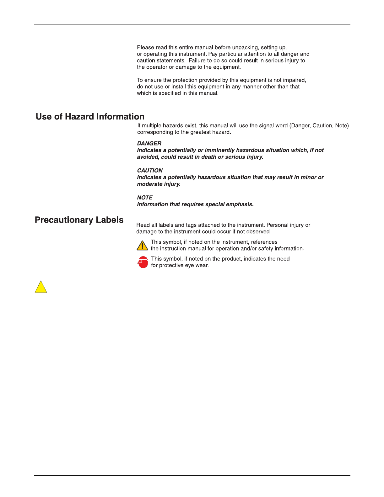
Safety Precautions
!
Section 5.3.1, AquaTrend Interface with Signal Output Module (SOM) to PS1201 Power
Supply Connections, on page 60.
Page 5
51350-18 safety page.fm Safety Precautions
Page 6

Specifications
Specifications are subject to change without notice.
Sensor input capability Eight
Operating humidity 5 to 95% non-condensing
Operating temperature 0 to 40 °C (32 to 104 °F)
Storage temperature -20 to 60 °C (-4 to 140 °F)
Power requirements Exter nal power supply 12 VDC nominal ±25%
(9 to 15 VDC range) with peak to peak ripple to be less than 10% of nominal.
Enclosure NEMA 4X (indoor), IP 66
Display visibility LCD backlit, visible at 10 feet with single reading; visible at 3 feet with multiple
readings.
Clock Real time
Mounting Wall, panel, or pole
®
Shipping weight AquaTrend
4 lb Portable AquaTrend Interface: 3 lb
Outputs (AquaTrend with SOM only) Two current analog outputs; range either 4-20 mA or 0-20 mA (user selectable);
both outputs isolated to 500 VDC; may be trimmed ±20% if needed (via AquaTrend
Interface).
Relays (AquaTrend with SOM only) SPDT 250 VAC, 5A resistive
Communications Echelon
between devices with a 500 meter maximum per segment; distances in excess of
500 meters require a repeater. Up to 3 repeaters can be used for a total network
length of 2000 meters.
Data logging capability 1 hour log (1 min. intervals), 30 day log (15 min. intervals)
AquaTrend Interface and AquaTrend/SOM
Capable of Master or Remote operation; the Master AquaTrend Interface is capable
of communicating with 34 Hach devices including:
8 sensors and/or analyzers
8 Signal Output Modules (SOM)
8 Digital Display Modules (DDM) or 8 Portable AquaTrend Interfaces
8 Remote AquaTrend Interfaces
2 Serial I/O Modules (SIO)
Function Network configuration, system setup, sensor calibration, data logging
Accessories Network terminator provided on the Signal Output Module (SOM) board or the
AquaTrend Interface. One required per network.
Interface or AquaTrend with Signal Output Module (SOM):
®
fieldbus compatible; utilizes LonTalk® protocol. Maximum of 400 meters
Page 6
Specifications
51350-18 specifications.fm
Page 7

Operation
Page 7
51350-18 operation stopper.fm Operation
Page 8

Visit http: //www.hach.com
Page 9

Section 1 General Description
Read this section of the manual to determine the appropriate system
configuration for your operation, and to familiarize yourself with basic
operating instructions before installing the AquaTrend
A Glossary of terms is provided on page 81 to help you understand the
AquaTrend Network.
1.1 Introduction
Hach’s AquaTrend Interface network system is designed to meet the needs of
small and large water analysis facilities alike. Unlike using a dedicated
controller for every instrument, the AquaTrend Interface network system uses
a single AquaTrend Module to interface a variety of devices. This enables
customization of systems to meet a variety of analytical testing needs. The
AquaTrend Interface network system utilizes a digital fieldbus communication
protocol called LonWorks to perform network operations and data
management tasks. Every device on an AquaTrend Interface network must be
identifiable in order to communicate with other AquaTrend Interface
network devices.
An AquaTrend Interface network system is built by adding an AquaTrend
Module to a sensor with a power supply and any other Hach peripheral
devices. Power and network connections are required for all AquaTrend
Interface devices operating on the network. After physically installing the
devices, you must add each device to the AquaT rend Interface network via the
network menus in the Master AquaTrend Interface. After adding all devices to
the network, you must designate which devices communicate with one
another. For example, once a sensor is attached to an AquaTrend Interface,
you must instruct the sensor to attach its reading to a designated AquaTrend
Interface display channel. Because many underlying network connections
occur when performing network operations, it is important to have all existing
devices on the network powered and operating normally when network
operations are conducted. Careful attention to network management
operations and the interconnection of devices will ensure successful operation
of the AquaTrend Interface network system.
®
Interface.
1.2 Using This Manual
This manual includes setup and operating instructions for AquaTrend
Interface, AquaTrend/SOM with integrated Signal Output Module, and
Portable AquaTrend Interface. If you are installing an AquaTrend/SOM and
want to include relay and analog output connections, see the Signal Output
Module (SOM) manual for information on making electrical connections.
Once you have gathered the necessary information to set up the AquaTrend
Interface and related sensors, read all instructions and warnings in Section 5
then proceed with the installation.
After making electrical and mechanical adjustments, read Section 2 to decide
which devices to include on the network. Then read and follow instructions in
Section 3 to set up communications between the AquaTrend Interface and
other network devices.
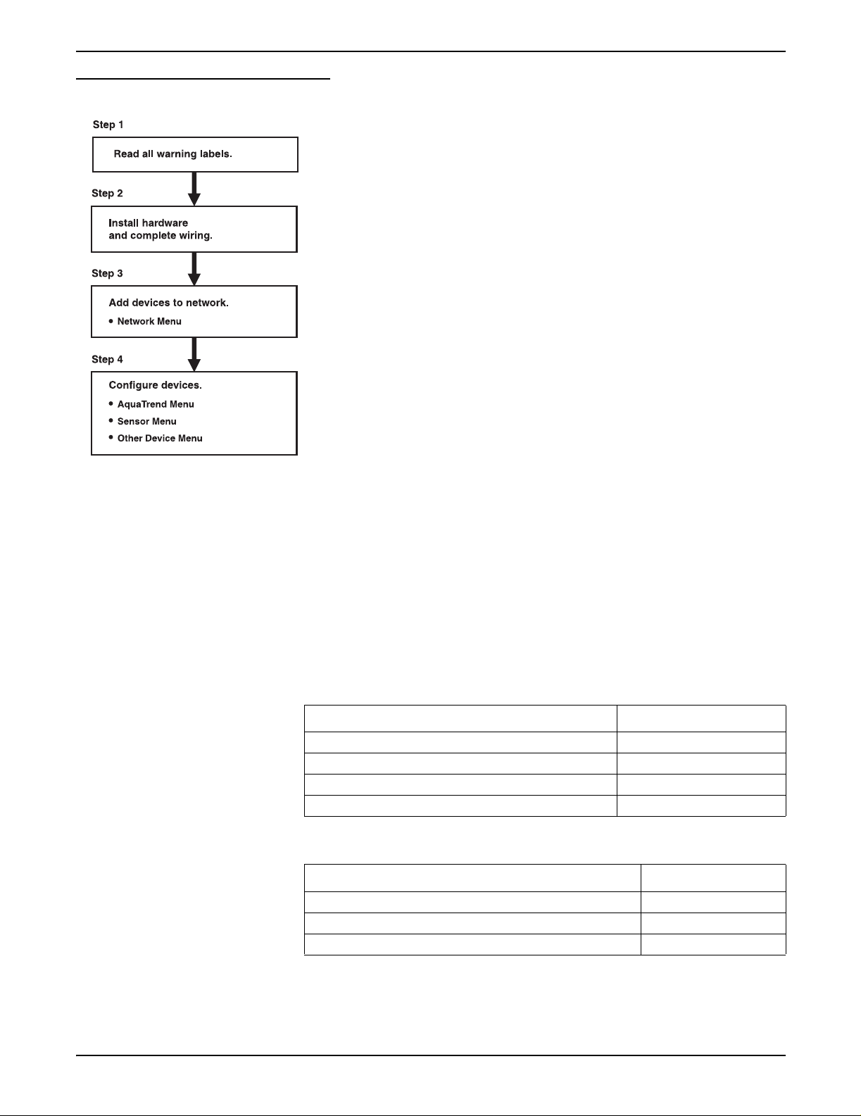
Figure 1 illustrates the basic installation sequence for all AquaTrend Interface
Network devices, except the PS1201 Power Supply, and includes references
to sections of this manual where instructions can be found.
Page 9
51350-18 general description.fm General Description
Page 10
Section 1
Figure 1 General Installation Information
Refer to Saf ety Prec autio ns on p age 5 and to the sections ref ere nced o n that p age .
Section 5 of this manual.
See the Quick Reference Guide and section 3.1.1 on page 23 of this manual.
Section 3 and Secti on 4
1.3 Unpacking the AquaTrend Interface
After opening the packing carton, remove the insulating foam and identify the
device you have received as an AquaTrend Interface, AquaTrend/SOM, or
Portable AquaTrend Interface. The AquaTrend Interface and AquaTrend/SOM
cartons contain the items listed in Table 1, and the Portable AquaTrend
Interface carton contains the items listed in Table 2. Remove the items from
the carton and verify that no visible damage has occurred during shipment.
Contact Hach Customer Service at 1-800-227-4224 if any items are missing
or damaged.
Table 1 Items Packaged with AquaTrend Interface and AquaTrend/SOM
Item Catalog Number
AquaTrend Interface or AquaTrend/SOM 51200-60 or 51350-60
Bracket, Wall Mount 51409-00
Cable Termination Kit 52156-00
Instruction Manual 51350-18
of this manual.
Page 10
Unpacking the AquaTrend Interface
Table 2 Items Packaged with Portable AquaTrend Interface
Item Catalog Number
Portable AquaTrend Interface with cable assembly 51400-60
Bracket, Wall Mount 51405-00
Instruction Manual 51350-18
51350-18 general description.fm
Page 11

1.3.1 Optional Equipment
Section 1
Additional items and devices can be obtained to expand the AquaTrend
Interface network system. Some of these items are shown below. A more
detailed description of network devices and network capabilities can be found
in Section 2.
Network Devices
• Serial I/O Module (SIO)
• Signal Output Module (SOM)
• Signal Input Module (SIM)
• Digital Display Module (DDM)
• AquaTrend Interface, AquaTrend/SOM, and Portable AquaTrend
Interface
• Sensors, including 1720D Turbidimeter
Other Equipment
• PS1201 Power Supply
• Floor stand
1.4 Instrument Description
The AquaT rend Interface provides a link between sensors and communication
devices. This networked system provides simplified use of multiple
instruments and requires fewer wiring configurations than systems without a
single digital wiring bus.
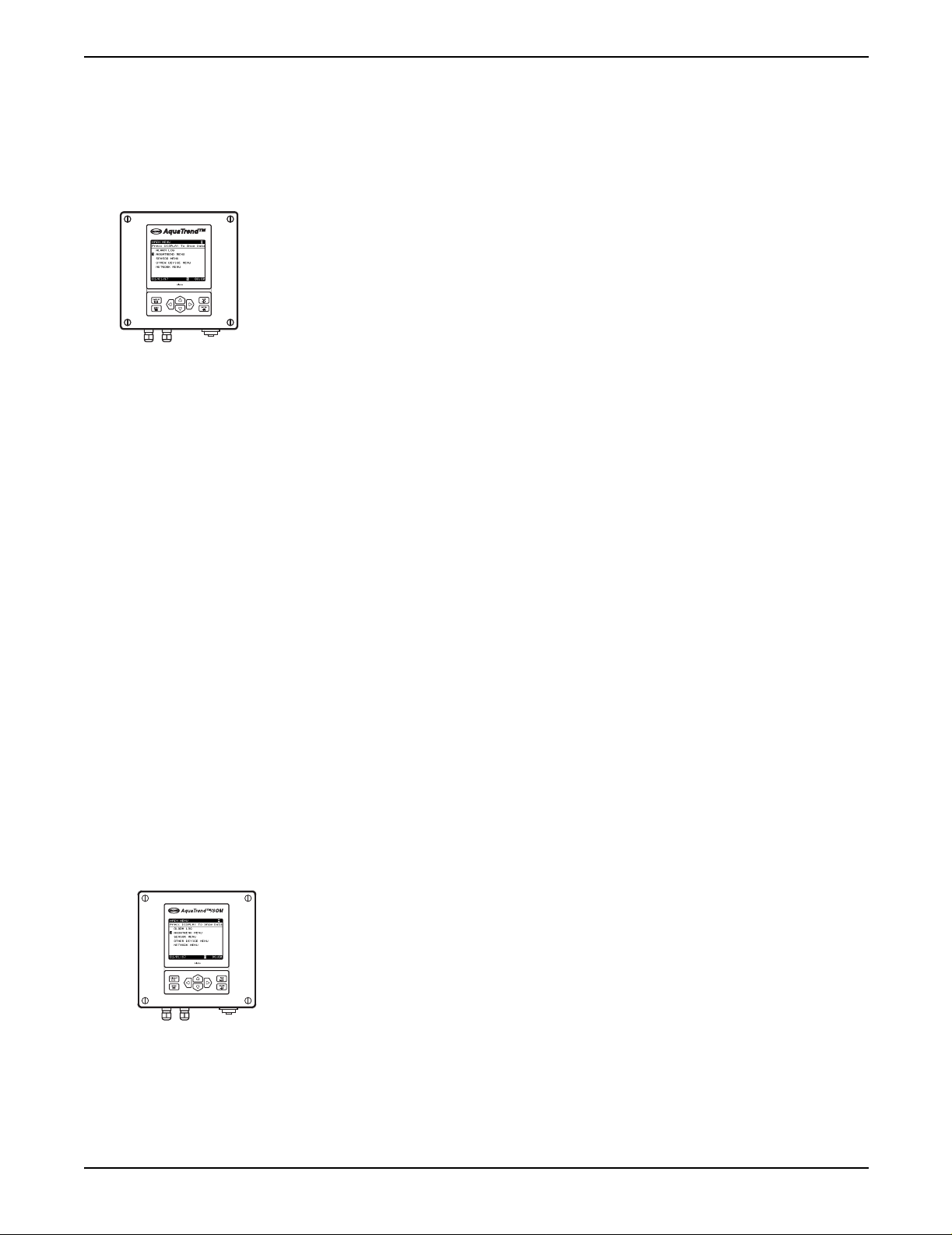
The AquaTrend Interface is available in three different physical configurations:
See section 2.2, De vice Descriptions on page 18 for additional information on
the different configurations.
1.4.1 Operating Environment
Place the AquaT rend Interface in an accessible location, where you can easily
see the display and operate the keypad. The backlit display is visible at 3 ft.
with multiple readings and at 10 ft. with single reading.
• U-bolts for floor stand or pole mounting
• Network repeater
• Cable
• AquaTrend Interface
• AquaTrend Interface with SOM
• Portable AquaTrend Interface
The AquaT rend Interface is designed to operate from 0 to 40 °C (32 to 104 °F)
and 5 to 95% relative humidity, non-condensing. The water-tight design meets
NEMA 4X (indoor) and IEC 529 IP66 enclosure requirements.
Page 11
51350-18 general description.fm Instrument Description
Page 12
Section 1
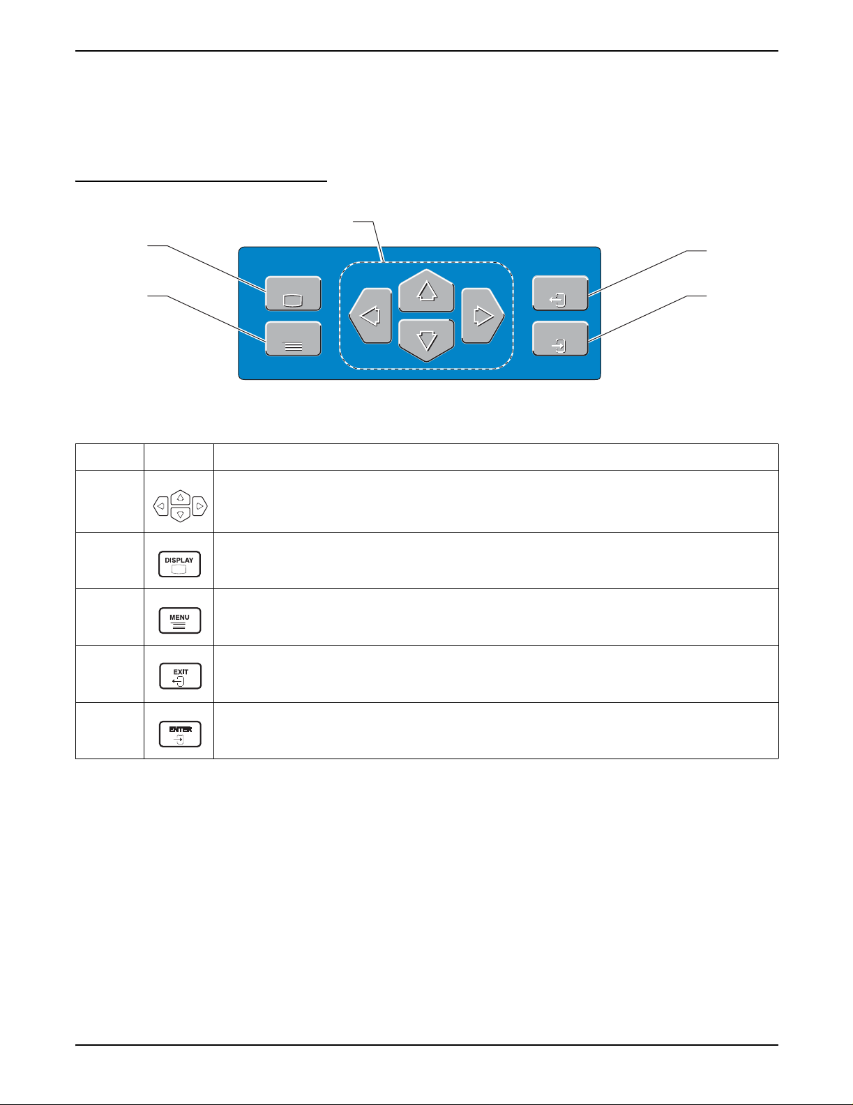
1.4.2 AquaTrend Interface Keypad Description
The AquaTrend Interface keypad is designed for straightforward
navigation through the AquaTrend Interface menus. The keypad contains four
arrow keys, a DISPLAY key, a MENU key, an EXIT key, and an ENTER key.
See Figure 2.
Figure 2 AquaTrend Interface Keypad
1
2
DISPLAY
3
DISPLAY
MENU
MENU
Table 3 AquaTrend Interface Key Functions
EXIT
EXIT
ENTER
ENTER
4
5
Number Key Function of Keys
Allows you to navigate through the various menus , to ch an ge s etti ngs, and to mov e th e cu rso r when
1
observing graph data.
Table 4 summarizes the functions of the arrow keys in each menu view.
2
Displays active data in numeric or graphical format.
Pressing the DISPLAY key toggles between data presented in numerical form and graphical form.
3 Displays the main menu from any menu level or from the data display.
From the Main Menu, pressing the EXIT key provides access to the data display screen.
4
From any other menu level, press the EXIT key to display the previous menu screen.
The EXIT key can also be used to abandon any alphanumeric entry or selection process.
5 Press while in any menu to accept menu options and confirm entries.
The arrow icons and their positions in the arrow field in the top right corner of
the display (item 7 on Figure 4) indicates the active arrow keys. For example,
if three arrow icons are present in the arrow field, pointing up, down, and right,
then the up, down, and right arrow keys can be used while viewing that
screen. Figure 3 shows examples of the screen categories with summaries of
the arrow key functions for each screen category.
Page 12
Instrument Description
51350-18 general description.fm
Page 13

Table 4 Arrow Ke y Functions
Screen Category Function
1. Menu Screen Move the pointer to next (down) or previous (up) item.
For menu s no longer than one page, the po inte r wi ll lo op around from the bottom to the top or
from the top to the bottom.
For multiple-page menus, the pointer will move to the next (down) or previous (up) page.
2. Numeric Data Display
Screen (1 to 8 numeric
readings)
3. Graph Display Screen Up: displays preceding channel graph.
4. Pop-up Entry Screen Increment (up) and decrement (down) currently highlighted character.
Left and Right Arrow: Changes the number of channels shown.
Press the Right Arrow to incr ease the num ber of chann els or press the L eft Arrow to dec rease
the number of channels.
Up and Down Arrow: changes the active channel designation.
Down: displays next channel graph.
Left and Right Arrow: moves curser if it is enabled.
If not enabled, changes the graph time base.
Move highlight to next (right) or preceding (left) character. Loop around at either end.
1.4.3 AquaTrend Interface Display Description
Press the DISPLAY key to alternate between displaying the data in numeric
and graphical mode.
Section 1
• Viewing data in numeric mode allows you to display from one to eight
measurements at the same time. When additional measurements are
shown on the screen, less information is displayed for those
measurements.
• Viewing data in graphical mode allows you to see a history of sensor
readings over the last 2 hours, 8 hours, 30 hours, 7 days, or 30 days,
depending on the graph time base selected. However, the AquaTrend
Interface displays data for only one channel at a time in the graphic mode.
For details on selecting the number of numeric channels of data shown and
the graph time base, see section 3.5.1 and section 3.5.2.
Press the MENU key to return to the Main Menu at any time. T o return to data
display mode, press either the EXIT or DISPLAY keys.
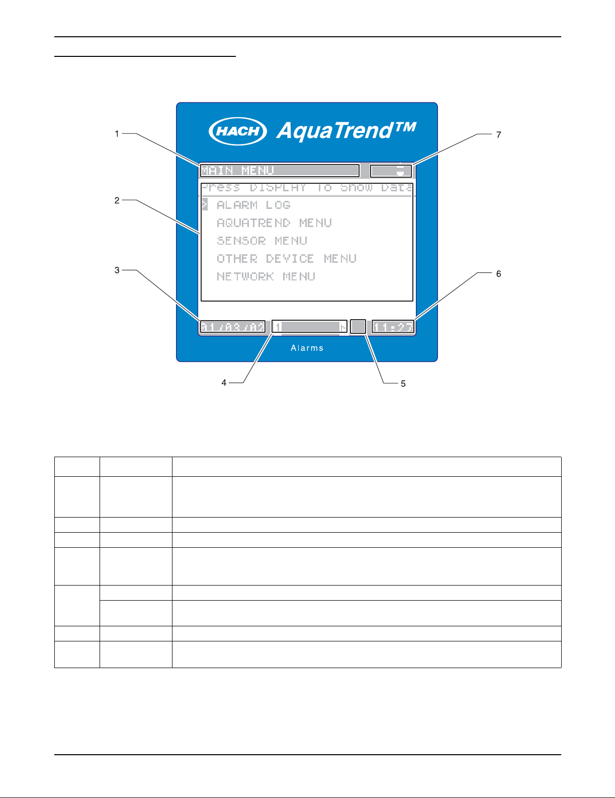
AquaTrend Interface screens appear in several different formats.
Sensor measurements are attached to separate channels, labeled A-P,
on the AquaTrend Interface. Refer to Figure 4 and Figure 5 for descriptions
of each field.
Figure 3 AquaTrend Interface Display Categories
1. Menu Screen 2. Numeric Data
Display Screen
51350-18 general description.fm Instrument Description
3. Graph Display Screen 4. Pop-up Entry Screen
Page 13
Page 14
Section 1
Figure 4 AquaTrend Interface Menu and Numeric Data Display Fields
Table 5 AquaTrend Interface Menu and Numeric Data Display Fields
Number Field Information Shown in Display Field
Numeric Data display: shows DISPLAY DATA
1 Status Bar
2 Text/Data Numeric data (1- 8 channels), graphical data, menus, and pop up boxes appear here.
3 Date Current date
4Alarms
Security Icon When displayed, indicates a security level of Partial or Total
5
6 Time Current time displayed as military time (24 hour clock).
7
Hourglass Icon
Navigation
Arrow
Main menu: shows MAIN MENU
Lower menus: shows top level menu (main menu item)
Numbers that appear here, 1 through 8, correspond to the sensor with active alarms. If “N”
appears in this field, a Network alarm is active. If no indicators appear in this field, no system
alarm is active. See section 4.2 on page 47 for information on reviewing alarms.
When displayed, indicates the datalog is completing a change.
The keyboard buffer is cleared when the icon disappears.
Direction of these arrow icons correspond to active arrow keys for each screen.
Page 14
Instrument Description
51350-18 general description.fm
Page 15
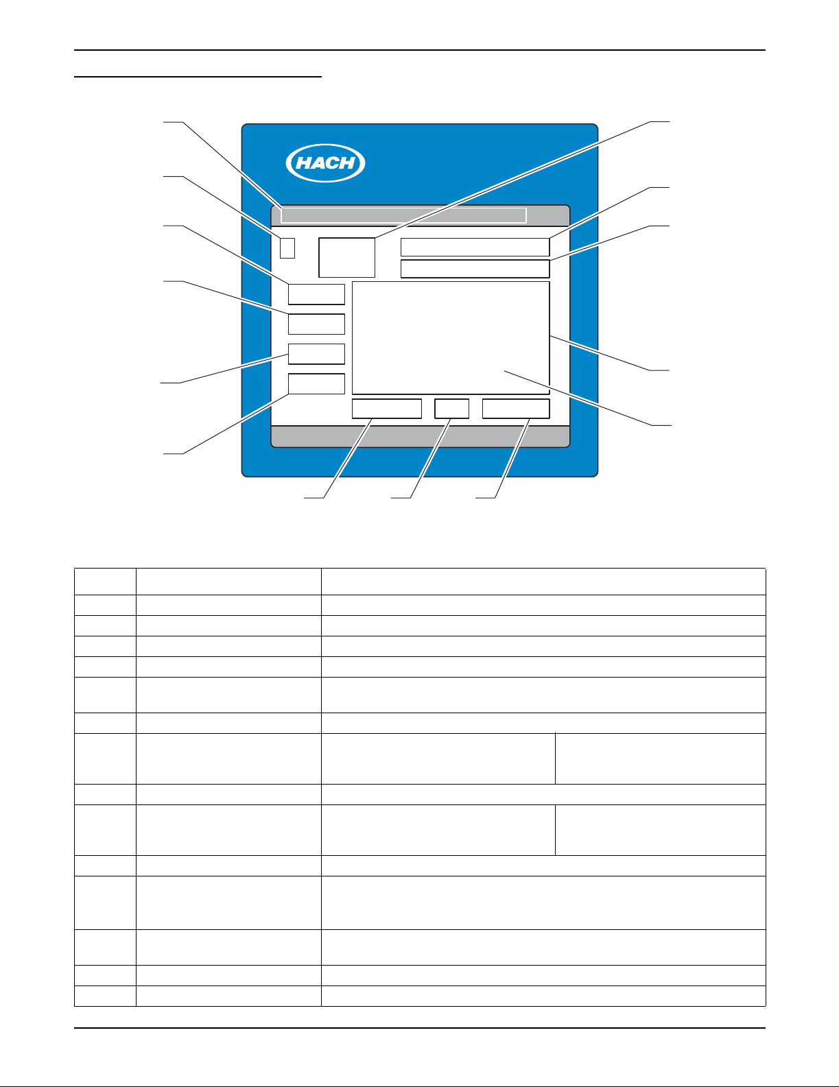
Figure 5 AquaTrend Interface Graph Fields
Section 1
1
2
3
4
5
6
AquaTrend™
Alarms
987
14
13
12
11
10
Table 6 Graph Field Descriptions
Number Field Information Shown in Graph Field
1 Status Bar Shows REVIEW MEASUREMENTS
2 Channel assignment Channel number of the measurement shown in the graph
3 Graph Da ta — Y-axis upper limit Upper numeric limit of trend graph data. (Ymax)
4 Cursor Y-data Y value of data at cursor position
5 Units/Species
6 Graph data — Y-axis lower limit Lower numeric limit of trend graph data (Y-min)
7 Graph time — X-axis low er li mit Lo wer time limit (oldest data).
8 Cursor Time/Dat e Time or date value of data at cursor position
9 Graph time — X-axis upp er lim it Curre nt time (lates t data) .
10 Graph Cursor Retrieves value of data at cursor position
11 Graph Area
12 Sensor name
13 Units and chemical form Units and chemical form of the measurement on the channel
14 Current Data Most recent measurement (same as numeric display)
Units and chemical form (where appropriate) of the measurement on the
displayed channel
If data is being reviewed in the
24 hour or 30 day mode, this field is
replaced with the date.
If data is being reviewed in the
24 hour or 30 day mode, this field is
replaced with the date.
Graph of 60 minutes, 8 hours, 24 hours, 7 days, or 30 days of data.
These settings are selectable in the DISPLAY SETUP menu (section 3.5.2 on
page 32).
Depending on the sensor type and configuration, the display shows
measurement name or the sensor location, or a combination of both.
Page 15
51350-18 general description.fm Instrument Description
Page 16

Section 1
1.5 AquaTrend Interface Menu Organization
The AquaTrend Interface main menu can be accessed at any time by
pressing the MENU key. The main menu categories are described in the
following sections.
1.5.1 Alarm Log
The alarm log menu provides a historical account of sensor specific alarm
information as well as AquaTrend Interface network alarm information.
1.5.2 AquaTrend Interface Menu
The AquaTrend Interface menu provides access to AquaTrend Interface
display and status settings. Display settings, language selection, time and
date settings, and security settings all reside in the AquaTrend Interface
menu. Access this menu to change the way information appears on the
AquaTrend Interface screen.
1.5.3 Sensor Menu
The sensor menu contains all sensor specific information including
calibration, alarm and recorder setup, measurement options, and sensor
diagnostics. The contents of this menu will change based on the sensor you
are working with. Since all of these menu items are stored within the sensor,
they are designed to be sensor specific. Access this menu to change sensor
settings or information.
1.5.4 Other Device Menu
1.5.5 Network Menu
The other device menu contains information specific to accessory devices
that are not sensors. Such examples include Signal Output Modules, Serial
I/O Modules and Digital Display Modules. Access this menu to change
settings or information for non-sensor devices.
The network menu contains information specific to performing network
operations. This includes adding, removing, and replacing devices on the
network. In addition, it contains menu items needed to establish
communications between devices. For example, once a sensor and Digital
Display Module are added to the system via the AquaTrend Interface, you
must instruct the sensor to attach its reading to the Digital Display Module.
Because many underlying network connections occur when performing
network operations, it is important to have all existing devices on the network
powered and operating normally when network operations are conducted.
Section 3 and Section 4 of this manual describe how to use these menus
together to build and configure your network.
Page 16
AquaTrend Interface Menu Organization
51350-18 general description.fm
Page 17
Section 2 Aquatrend® Interface Network
2.1 Network Description
This section describes requirements and options for setting up the AquaTrend
Interface Network System. A “network” is the connection of one or more
devices (of which at least one is a sensor) to a Master AquaTrend Interface.
This Master AquaTrend Interface serves as the network control panel.
Devices can include Signal Output Modules (SOM), Digital Display Modules
(DDM), Serial I/O Modules (SIO), Remote AquaTrend Interf aces and
Portable AquaTrend Interfaces.
Figure 6 shows an example of a single-sensor AquaTrend Interface Network
System. An example of a multi-sensor system is shown in Figure 7.
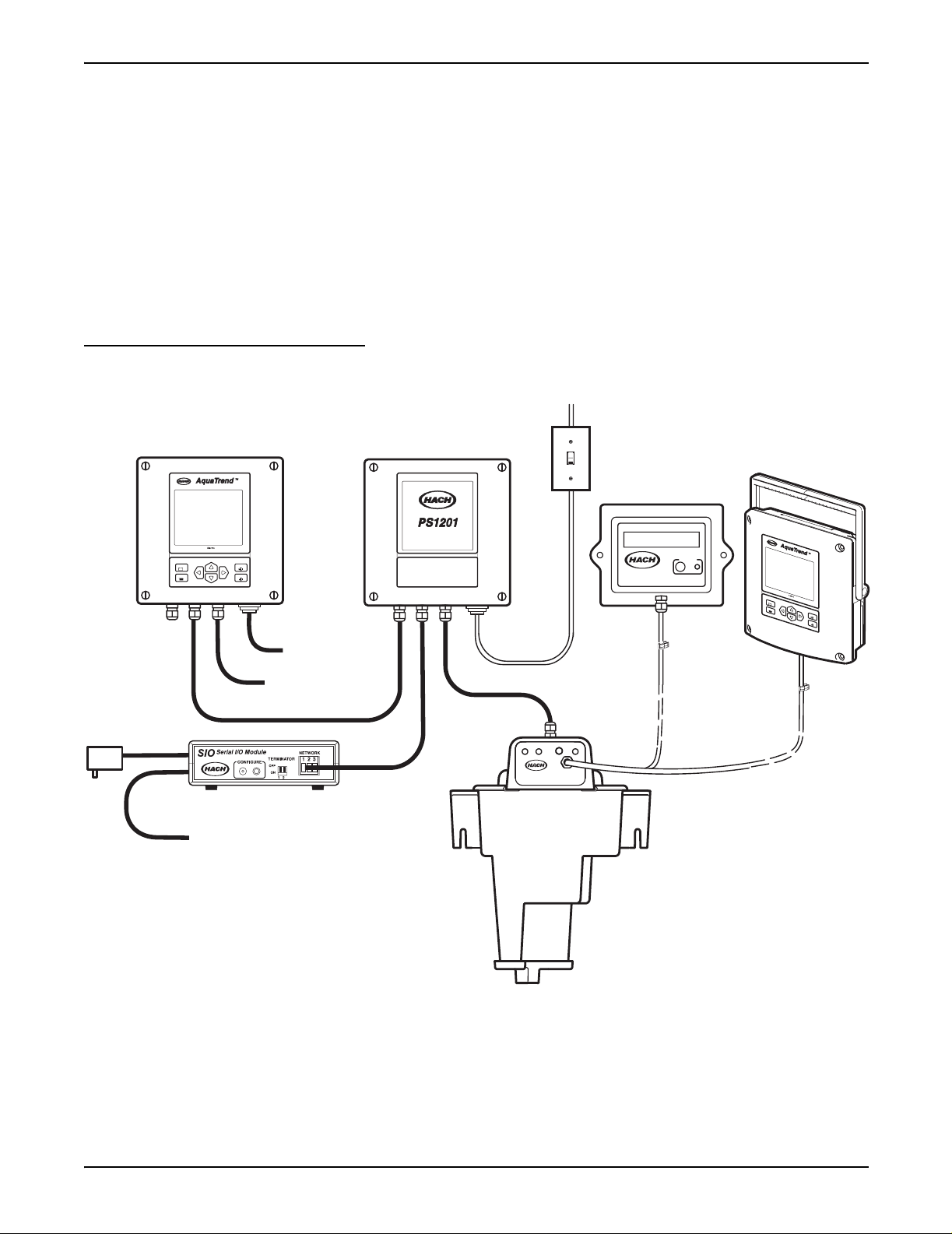
Figure 6 Single-Sensor AquaTrend Interface Network
115 / 230 VAC
Power In
Customer Supplied
ON/OFF Switch
ON
OFF
expansion
AC Power
Spare -
open for
DISPLAY
MENU
EXIT
ENTER
Relays
4-20mA Outputs
RS232 Computer or Printer Interface
Power Supply 12V DC
Network Connection Module
1720D
DIGITAL
DISPLAY MODULE
CONFIGURE
D
I
S
P
M
E
N
Either the
DDM or the
Portable AquaTrend
L
A
Y
U
E
X
I
T
E
N
T
E
R
Each sensor (i.e., the 1720D Turbidimeter) manual provides instructions for
setup of the single-sensor network. Each of the other device manuals,
(AquaTrend/SOM, AquaTrend Interface, Digital Display Module, Serial I/O
Module, Signal Input Module and Signal Output Module) provides setup
instructions for their components.
Section 2.3
describes the maximum
number of devices that can be managed by one Master AquaTrend Interface
on a system.
51350-18 Aquatrend Interface Network.fm Aquatrend
®
Page 17
Interface Network
Page 18
Section 2
2.2 Device Descriptions
2.2.1 AquaTrend Interface Module
The two primary functions of the AquaTrend Interface are network
management and data display. Network management functions are required
only when performing modifications to the network such as adding or
removing devices. Multiple AquaTrend Interfaces (up to nine) can exist on a
network at any given time. Remote AquaT rend Interfaces serve to display data
from one or more sensors and access sensor menus.
• Master AquaTrend Interface – Acts as the main network data control
center for setup and operation of the network. The network can contain as
many as nine AquaTrend Interfaces but only one can be the Master
AquaTrend Interface. Only through the Master AquaTrend Interface can
network operations be performed.
• Remote AquaTrend Interface – Any AquaTrend Interface on a network
that is not a Portable or Master AquaTrend Interface. Remote AquaTrend
Interfaces can control and monitor all sensors on the network. Remote
AquaTrend Interfaces cannot perform network operations such as adding
and removing devices.
• Portable AquaTrend Interface – Mobile device designed for set up and
calibration of sensors already on the network. Portable AquaTrend
Interfaces can communicate with one sensor at a time and cannot
perform network operations. See section 2.2.3 and 5.2 for more
information about the Portable AquaTrend Interface.
All AquaTrend Interfaces have the capability of functioning as a Master or
Remote however, only the Master AquaTr end Interface is allowed to perform
network management functions. All AquaTrend Interfaces are shipped from
the factory in an undefined (neither Master or Remote) state. When an
individual AquaTrend Interface is defined as the Master, any other AquaTrend
Interface on the network must be defined as a Remote. An AquaTrend
Interface can be redefined (i.e., Remote to Master or Master to Remote);
however , e xisting network connection information will be lost. After changing a
Remote to a Master AquaTrend Interface, you must rebuild the network and
reestablish communications between devices.
2.2.2 AquaTrend/SOM with Integrated Signal Output Module
The AquaT rend/SOM Module is a combined AquaTrend Interface and SOM in
one enclosure. See section 2.2.1 for information concerning the functions and
options for the AquaTrend Interface portion of the combined AquaTrend/SOM
and section 2.2.5 for more details about the SOM.
Page 18
Device Descriptions
51350-18 Aquatrend Interface Network.fm
Page 19
2.2.3 Portable AquaTrend Interface Module
The Portable AquaTrend Interface can access sensor menus for setup and
calibration but cannot perform network management functions. The Portable
AquaTrend Interface communicates directly to the sensor that it is attached to
without interpreting network commands from the Master AquaT rend Interface.
Once a network is configured using a Master AquaTrend Interface, the
Portable AquaTrend Interface can be used to display and log data from that
sensor in the absence of a Master AquaTrend Interface.
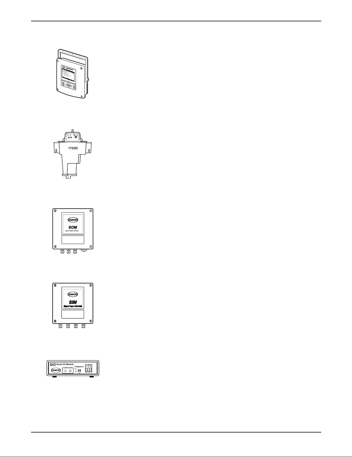
2.2.4 Sensor
The sensor, such as the 1720D Turbidimeter (shown at left), is the
device that analyzes the sample. Sensors may or may not contain an
AquaTrend Interface.
Section 2
2.2.5 Signal Output Module (SOM)
Each SOM provides two relays, each with normally open and normally closed
contacts rated at a maximum of 5A/250 VAC, and two analog outputs,
selectable through the AquaTrend Interface keypad at either 4-20 or 0-20 mA.
Signal Output Module functionality can be provided either in an
AquaTrend/SOM or in a separate Signal Output Module. See the
Output Module Manual
2.2.6 Signal Input Module
The Signal Input Module (SIM) is configured as a sensor on the network
system and provides two 4-20mA analog inputs. These inputs can be used to
bring measurements from non-networked sensors into the network. The SIM
allows the user to set the value for zero and full-scale inputs and to define the
measurement names, units, and species. Two configurable setpoint alarms
can be set to trigger relays in a Signal Output Module. Refer to the
Input Module (SIM) Manual
2.2.7 Serial I/O Module (SIO)
The AquaTrend Interface allows the review of data collected over the last 60
minutes, 24 hours, or 30 days. To download the data to a computer or printer,
a Serial I/O (SIO) Module must be installed. The SIO provides two-way
communication with a computer (PC) or one-way communication with a
printer. Use an SIO to permanently log measurement and diagnostic data to a
printer or computer. See the
for detailed information.
for additional information.
Serial I/o Module Manual
Signal
Signal
for detailed information.
Page 19
51350-18 Aquatrend Interface Network.fm Device Descriptions
Page 20

Section 2
2.2.8 Digital Display Module (DDM)
The Digital Display Module (DDM) is an eight-character display that can be
attached to sensors to provide a local digital reading. Once the display is
added to the network and assigned to the sensor by the Master AquaTrend
Interface, it will automatically display data from the sensor. For sensors that
have multiple parameters (measurements), you can choose which parameter
you want to display on the DDM. See the
detailed information.
2.2.9 Repeater Module
The AquaTrend Repeater module is a physical layer repeater used to extend
the length of the AquaTrend Network by a maximum of 500 meters. A total of
three such devices can be installed on the AquaTrend Network to extend the
total length of the network to 2000 meters.
2.3 Network Design
Based on Wiring Topologies on page 83, determine the appropriate
configuration for your operation by considering the following criteria;
descriptions of each device is given in section 2.2.
Digital Display Module Manual
for
Table 7 Maximum Network Capabilities
Device
Signal Output Module (SOM) 8
Serial I/O Module (SIO) 2
Digital Display Module (DDM) 8
Sensors (A SIM is seen by the network as a sensor.
Maximum sensors + SIMs = 8)
AquaTrend Interface 1 Master, 8 Remotes
Note: All AquaTrend Interfa ces on a
system display measurements and
menus, but only the Master
AquaTrend Interface can perform
network operations through the
Network Menu.
The system can contain as many as nine AquaTrend Interfaces but only
one can be the Master AquaTrend Interface. Each AquaTrend Interface
is programmed in an undetermined state when shipped from the factory
and must be designated as a Master or Remote when initially attached to
the network.
Number of devices that can be maintained on one
AquaTrend Interface Network
8
If more than one AquaTrend Interface is to be attached to the network,
the Master AquaTrend Interface will be designated before other
AquaTrend Interfaces are added. Additional AquaTrend Interfaces will be
designated as Remotes.
Select the number of PS1201s based on the wattage needed and the
distance between the power supplies and the devices. Each PS1201
Power Supply provides 25 watts. Available devices and their wattages are
listed below and in the PS1201 manual.
Page 20
Network Design
If a system larger than 35 nodes is needed, refer to the information on
assigning subnet addresses in Appendix A Use of Subnets on page 75.
51350-18 Aquatrend Interface Network.fm
Page 21

Table 8 Wattage Requirements for AquaTrend Interface Devices
Device Power Required (watts)
AquaTrend/SOM 5
AquaTrend Interface 2
Portable AquaTrend Interface 2
Digital Display Module (DDM) 2
Signal Output Module (SOM) 3
Signal Input Module (SIM) 2
Serial I/O Module (SIO) Provides its own AC (wall plug) power supply.
1720D Turbidimeter (sensor) See the 1720D Turbidimeter manual
Section 2
Page 21
51350-18 Aquatrend Interface Network.fm Network Design
Page 22
Section 2
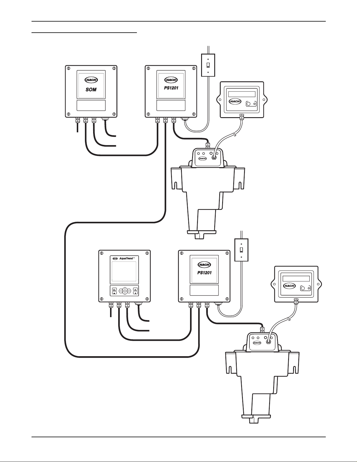
Figure 7 Example of Multi-Sensor Setup
115 / 230 VAC
ON
Power In
OFF
Customer Supplied
ON/OFF Switch
Signal Output Module
For
Network
Expansion
Network Communications Cable
Relay Contacts
4-20 mA Outputs
Power Supply 12V DC
Network Connection Module
1720D
DIGITAL
DISPLAY MODULE
ON
OFF
CONFIGURE
115 / 230 VAC
Power In
Customer Supplied
ON/OFF Switch
Page 22
Network Design
For
Network
Expansion
Power Supply 12V DC
Network Connection Module
DISPLAY
MENU
EXIT
ENTER
DIGITAL
DISPLAY MODULE
CONFIGURE
Relay Contacts
4-20 mA Outputs
1720D
51350-18 Aquatrend Interface Network.fm
Page 23
Section 3 Initial AquaTren d Setup
3.1 Identifying the Master AquaTrend
Every AquaT rend® Interface Network System requires a network manager
to perform network operations, such as adding or removing devices.
The AquaTrend and AquaTrend with SOM can perform network
management functions when set to Master AquaTrend status through the
AquaTrend software; however, only one Master AquaT rend can be present on
the network at a time. All other AquaTrends must be set to Remote AquaT rend
status. Care should be taken when determining the location of the
Master AquaTrend Interface.
Every AquaT rend Interface is shipped in an undefined state. When connecting
only one AquaTrend Interface to the network, it must be designated as the
Master AquaTrend Interface.
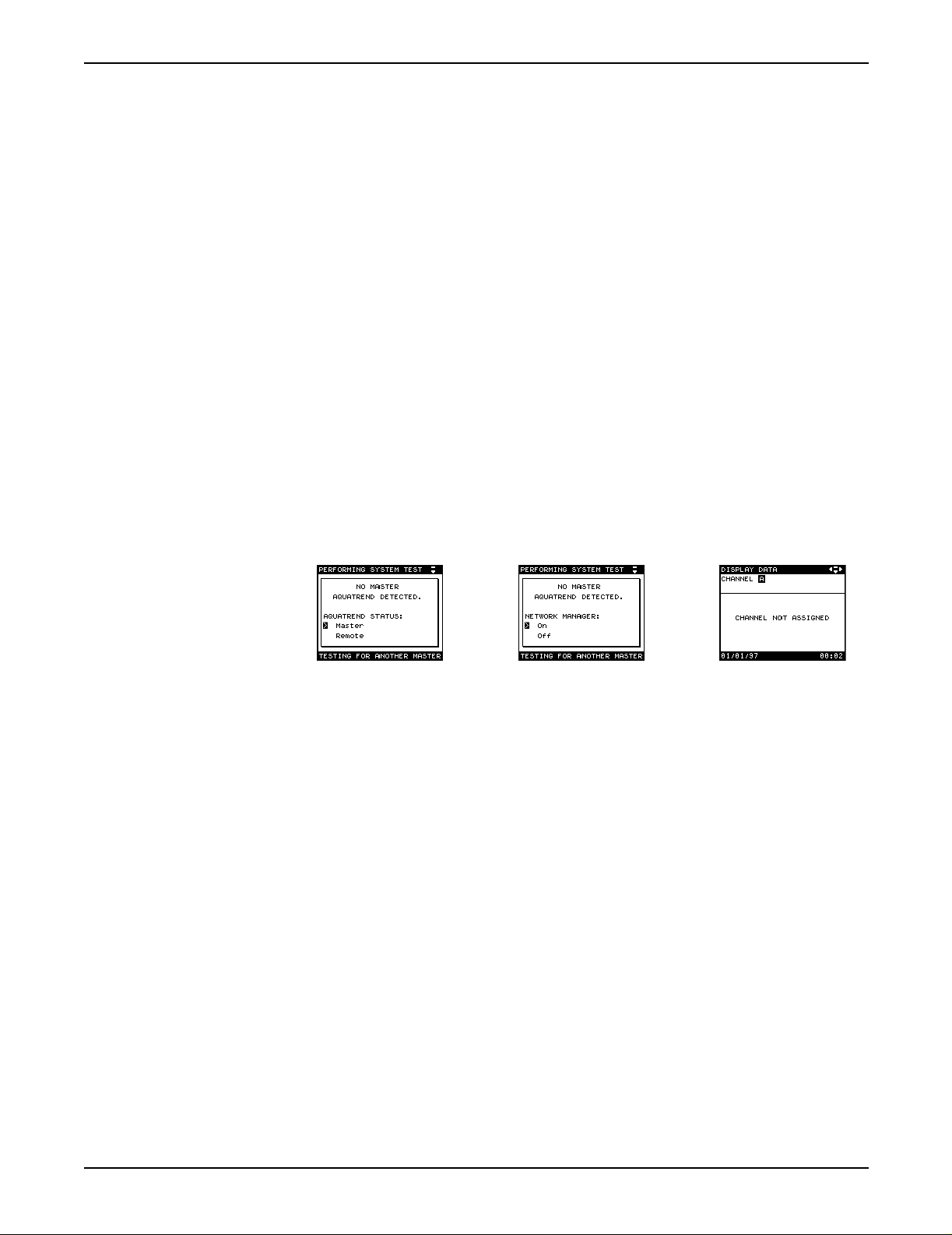
Set the system AquaTrend Interface to Master status as follows:
1. Upon initial power-up, select MASTER and press the ENTER key.
2. Press Enter to select Network Manager to ON. After a brief delay, the
display will show the data display screen (CHANNEL NOT ASSIGNED).
3. Press the Menu key to proceed to the Main Menu.
3.1.1 Adding Remote AquaTrend Interfaces to the Network
Upon power up, new AquaTrend Interfaces on the network will search for a
Master AquaTrend Interface. (The exception is when installing an AquaTrend
Interface that has previously been installed as part of another AquaTrend
network. In this case, the AquaTrend that is new to this network will not
automatically check for a master. To force it to check, press the EXIT key
when instructed to install the remote from the network manager.)
Once a master is identified, the additional AquaTrend Interfaces will assume
remote AquaT rend Interface status and can be added to the network using the
instructions in section 3.4.2, Adding a Device to the Network.
The Master AquaTrend Interface should not be changed to a remote unless
you want to change the location where network operations are performed.
A change from Master to Remote AquaTrend Interface status will erase all
network information, requiring you to restore network connections.
See section 3.12 on page 41.
Page 23
51350-18 Initial Aquatrend Setup.fm Initial AquaTrend Setup
Page 24
Section 3
3.2 Language Setting
3.3 Time/Date Setting
3.3.1 Setting the Time
English is the default language of the AquaTrend Interface Network System.
To display another language, follow the instructions below:
1. Press the MENU key to begin at the Main Menu.
2. Use the up or down arrow key to select AQUATREND MENU and
press ENTER.
3. Select LANGUAGE and press ENTER.
4. Use the up or down arrow keys to move the pointer to the desired
language and press ENTER. All screens will be displayed in the
selected language.
Verify the time and date are correct. If necessary, change them as instructed
in the following sections.
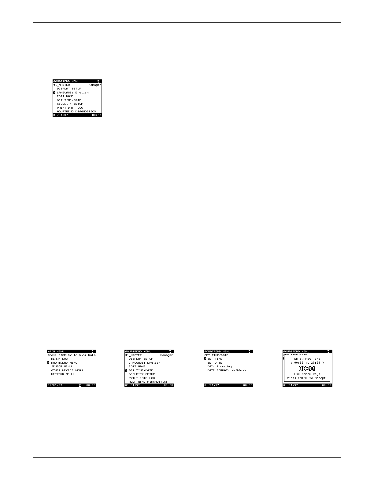
1. Press the MENU key to access the Main Menu.
2. Use the up or down arrow key to move the pointer to AquaTrend Menu
and press ENTER.
3. Select the SET TIME/DATE option and press ENTER.
Note: The AquaTrend Interface uses a 24-hour clock (military time), so there is no
selection for a.m. and p.m. For example, if the current time is 4:00 p.m., enter the
24-hour format equivalent of 16:00.
a. Select SET TIME.
b. A pop-up box will prompt you to enter the new time. The numbers
representing the hour will be highlighted.
c. Press the up arrow key to increase the hour setting and press the
down arrow key to decrease the setting.
d. When the proper hour is displayed, press the right arrow key and set
the minutes as in step c above.
e. Press ENTER to accept the displayed value, or press EXIT to cancel.
Page 24
Language Setting
51350-18 Initial Aquatrend Setup.fm
Page 25
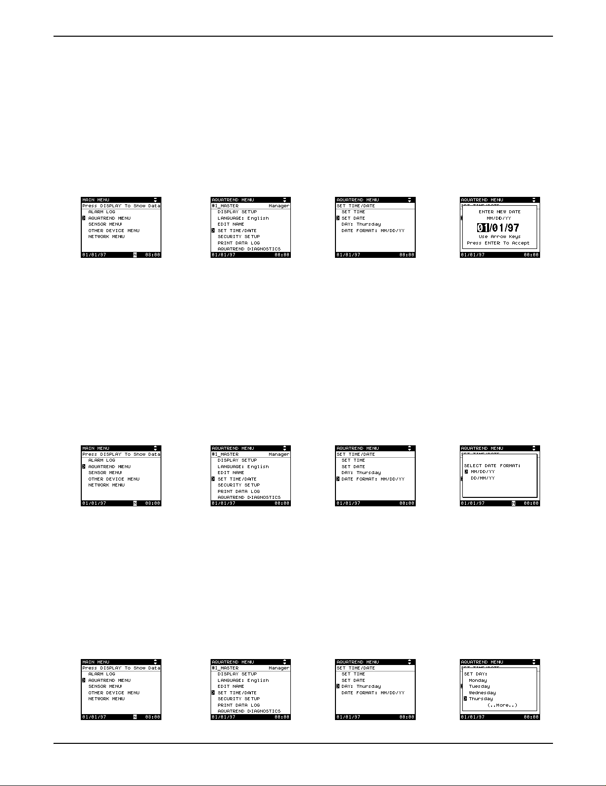
3.3.2 Setting the Date
Section 3
1. Press the MENU key to access the Main Menu.
2. Use the up or down arrow key to move the pointer to AquaTrend Menu
and press ENTER.
3. Select the SET TIME/DATE option and press ENTER.
a. Select t he SET DATE option and press ENTER.
b. A pop-up box will prompt you to enter the new date.
c. Press the up and down arrow keys to increment through the available
digits. Press the right or left arrow key to move to another character
field wi thin the date.
d. When the proper date is displayed, press ENTER to accept or press
EXIT to cancel.
3.3.3 Changing the Date Format
a. To change the date format, select DATE FORMAT from within
the Set Time/Date Menu. A pop-up box will appear requesting
SELECT DATE FORMAT.
b. Select the preferred date format – MM/DD/YY is month/day/year, and
DD/MM/YY is day/month/year.
3.3.4 Setting the Correct Day of the Week
The internal calendar programs the day of the week to correspond to the set
date. If it is necessary to change the day, proceed as follows:
a. To change the day of the week, select DAY from within the
SET TIME/DATE menu. To change the day setting, which shows the
current day of the week, select DAY.
b. Mov e the p ointer t o the correc t da y and pres s the ENTER ke y. The day
will move forward automatically with the clock at 24:00 hours.
Page 25
51350-18 Initial Aquatrend Setup.fm Time/Date Setting
Page 26
Section 3
3.4 Network Setup
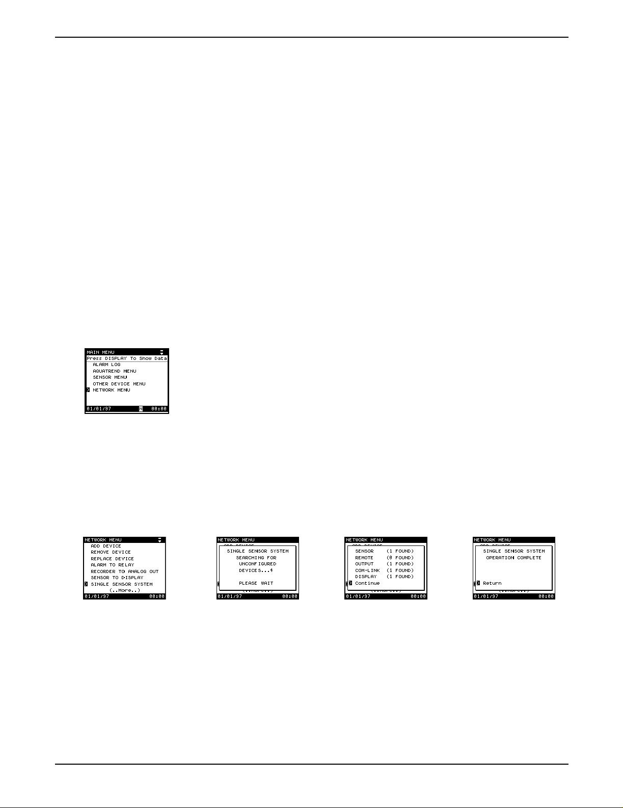
3.4.1 Single Sensor System
A “network” is the connection of one or more devices (at least one must be a
sensor) to one or more AquaTrend Interfaces. A “device” can be an additional
1720D sensor, Digital Display Module (DDM), Serial I/O module (SIO), Signal
Output Module (SOM), or a remote AquaTrend Interface.
Up to eight sensors, eight Digital Displays, eight remote AquaTrend
Interfaces, eight Signal Output Modules, two Serial I/O Modules and all
necessary power supplies may be attached to the network.
The two procedures for adding device(s) to the network are presented in
section 3.4.1 and section 3.4.2.
Use this feature when installing a complete system with no more than
(1) Sensor (the 1720D Turbidimeter is being used in this example),
(1) Master AquaTrend Interface, (1) SOM (as an integral part of an AquaT rend
Interface or as a separate device), (1) SIO, (1) DDM, and (1) remote
AquaTrend Interface. During this procedure, the default device settings are
accepted and sensor measurements are automatically assigned to
appropriate channe ls.
1. Press the MENU key to access the Main Menu.
2. Choose Network Menu.
3. Select SINGLE SENSOR SYSTEM.
A pop-up box will appear stating SINGLE SENSOR SYSTEM
SEARCHING FOR UNCONFIGURED DEVICES.
4. If the system is correctly installed, the display will next show a pop-up box
listing all devices found. Press ENTER to install the single sensor system.
5. After configuration, the display will show OPERATION COMPLETE.
6. Press the DISPLAY key to show sensor data.
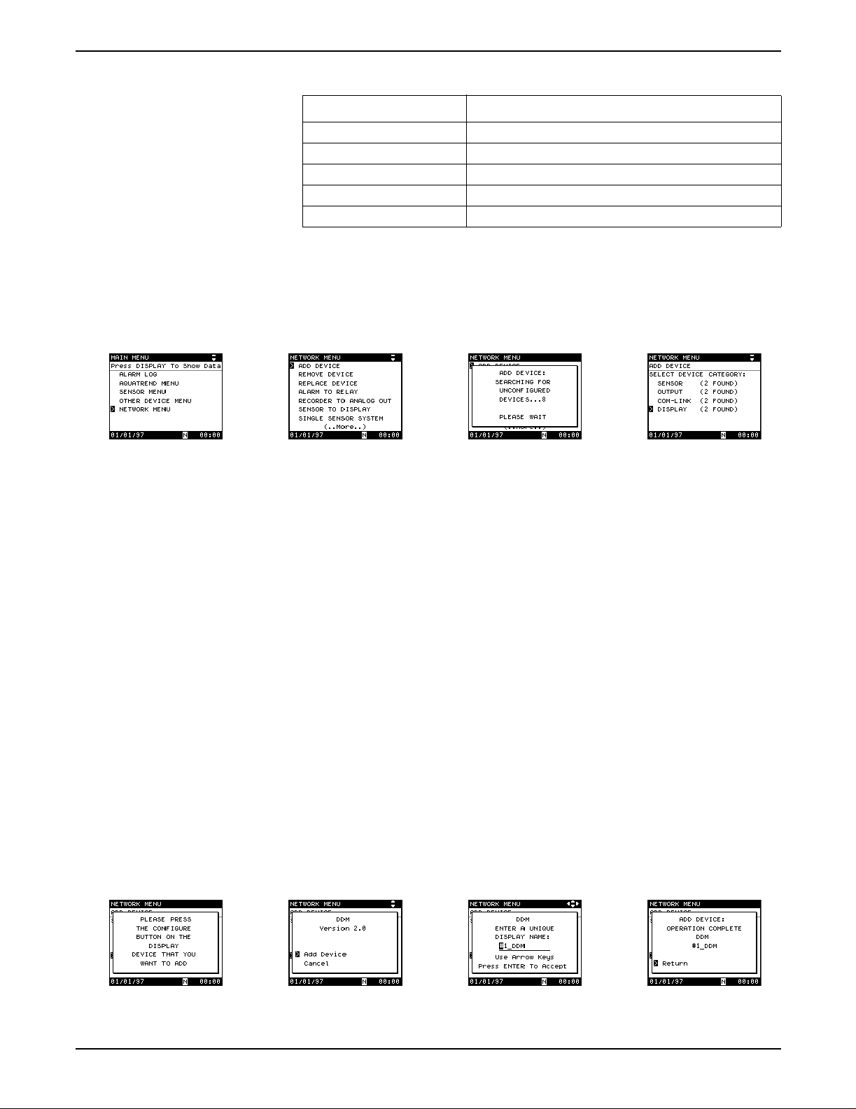
3.4.2 Adding a Device to the Network
Table 9 presents available device types. Follow the procedure below to add a
device. Repeat as many times as is necessary to add all needed devices to
the network.
Page 26
Network Setup
1. Press the MENU key to start from the AquaTrend Interface Main Menu.
2. Press the down arrow key to move the pointer to NETWORK MENU and
press ENTER.
51350-18 Initial Aquatrend Setup.fm
Page 27
Section 3
Table 9 AquaTrend Interface Device Types
Device Type Devices
Sensor 1720D Turbidimeter, any APA6000 Analyzer or SIM
Com-Link Serial I/O Module (SIO)
Outputs Signal Output Module (SOM)
AquaTrend Interface Remote AquaTrend Interface
Display Digital Display Module (DDM)
3. Select ADD DEVICE and press ENTER.
A pop-up box will show: SEARCHING FOR UNCONFIGURED
DEVICES...PLEASE WAIT.
4. If only one unconfigured device type is connected to the network it will be
selected automatically; if more than one type of unconfigured devices is
found, select the device type to be added.
Note: Press the Confi gure button on th e d evice to be add ed (press the ENTER key on
the AquaTrend Interface) or continue with Step 5 and 6 to make the device
selection via the AquaTrend Interface software.
5. If only one unconfigured device of the selected type is available, it will be
selected automatically; if two or more devices of the same type are
available, the AquaTrend Interface will ask you to press the configure
button on the device you want to add.
6. Press the configure button on the device to be added, if necessary.
Refer to the device’s manual if you do not know where to find its
configure button.
7. Select ADD DEVICE and press ENTER.
8. The AquaTrend Interface will configure the device and suggest a name.
Change the name if necessary, see section 3.7 on page 33.
Press ENTER
to confirm the name.
The pop-up screen will confirm that the operation is complete.
Page 27
51350-18 Initial Aquatrend Setup.fm Network Setup
Page 28
Section 3
3.4.3 Removing or Replacing a Device
The remove device procedure is used to remove a device from the network.
Doing so will lose all information related to the device.
The replace device procedure is used to replace an existing device with an
identical new device. The replace device procedure loses device-specific
settings, such as alarm level, measurement options, calibration, and sensor
diagnostic settings. The procedure retains network settings, such as alarm to
relay connections, and the device name.
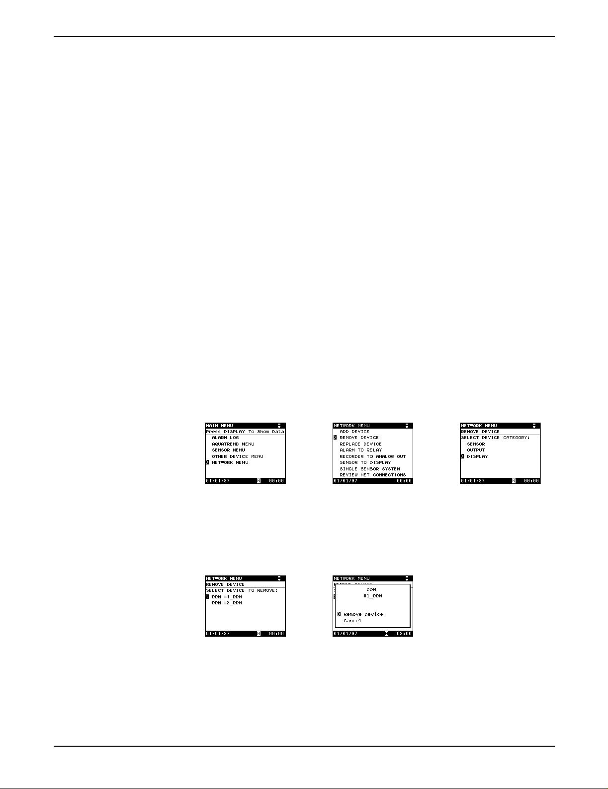
3.4.3.1 Removing a Device from the Network
Before physically removing a device from the system, this remove device
software procedure must be performed. This assures that all network
communications associated with the device are properly removed to avoid
miscommunication from other devices on the network. Proceed as follows:
1. Press the MENU key to access the Main Menu.
2. Use the up or down arrow key to move the pointer to NETWORK MENU
and press ENTER.
3. Select REMOVE DEVICE and press ENTER.
4. From the list of device categories, select the device type to be removed
and press ENTER.
Note: Press the Configure button on the device to be removed (press the ENTER key
on the AquaTrend Interface) or continue with Step 5 and 6 to make the device
selection via the AquaTrend Interface software.
5. Select the specific device to remove and press the ENTER key.
6. Press ENTER to remove the device or move the pointer to CANCEL to
end the operation without changes.
Page 28
Network Setup
51350-18 Initial Aquatrend Setup.fm
Page 29
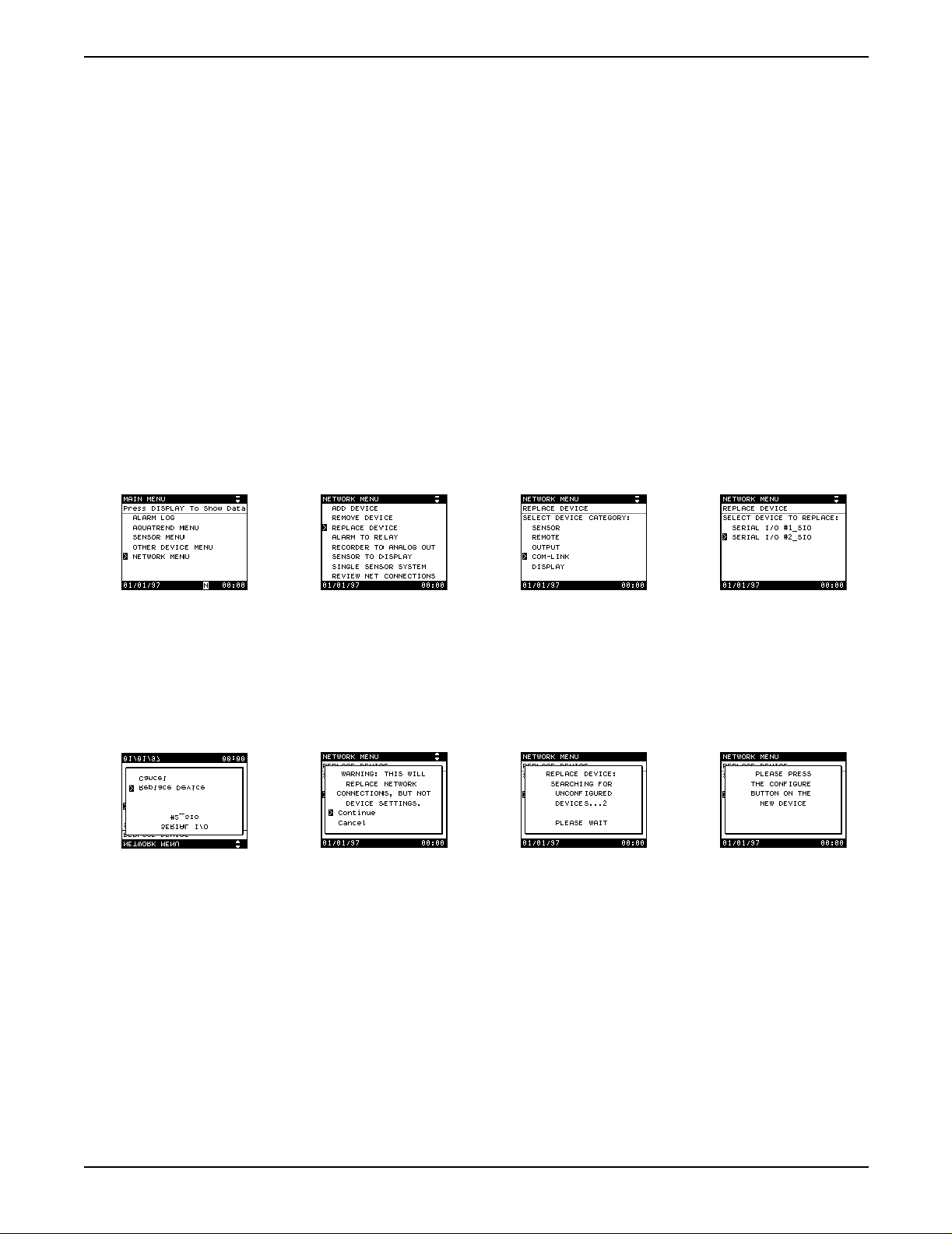
3.4.3.2 Replacing a Device on the Network
Before beginning the replace device procedure, the new device must be
physically attached (wired) to the network and powered. Refer to the
installation section in the device manual for information.
1. Press the MENU key to access the Main Menu.
2. Use the up or down arrow key to move the pointer to Network Menu and
press ENTER.
3. Select REPLACE DEVICE and press the ENTER key. A list of devices to
replace will appear.
4. Select the type of device to replace and press ENTER.
5. Select the device to replace (if more than one device is available for
replacement) and press ENTER. Or, press the configure button on the
device you want to replace (press the ENTER key on a remote AquaTrend
Interface). If only one device to replace is available, it will be selected
automatically.
Section 3
6. A pop-up box will appear showing the device to be replaced. If it is
correct, choose REPLACE DEVICE.
7. A warning pop-up box will appear. Select CONTINUE and press the
ENTER to continue with the replacement.
8. A search for available replacement devices will begin. If more than one is
found, press the configure button on the replacement device (press the
ENTER key on a remote AquaTrend Interface).
9. When the replace procedure is complete, a status screen appears. Press
the ENTER key to acknowledge and continue normal operations.
10. Now that the device has been replaced you must verify and/or replace all
device specific settings.
Page 29
51350-18 Initial Aquatrend Setup.fm Network Setup
Page 30

Section 3
3.4.4 Attaching a Measurem ent to a Channel
Although sensors may have been added to the network, readings will not be
displayed until a measurement is attached to a channel. AquaTrend Interface
sensors can report one or more measurements, depending on the type of
sensor. Attach each sensor measurement to one of the eight AquaTrend
Interface channels when setting up a new sensor.
1. Press the MENU key to begin at the Main Menu.
2. Use the up or down arrow key to select the AquaTrend Menu and
press ENTER.
3. Select DISPLAY SETUP and press ENTER.
4. Select MEASUREMENT TO CHANNEL and press ENTER.
5. Select ATTACH, and press ENTER. A list of available sensors will appear.
6. Select the sensor of interest and press ENTER.
7. Select the channel of interest and press ENTER.
• If the sensor has more than one measurement available, select the
desired measurement and press ENTER.
8. Select ATTACH and press ENTER to continue, or select Cancel to cancel
the attachment.
The message OPERATION COMPLETE will appear. The screen will return to
the display setup menu upon completion of the measurement to channel
setup. To see the data display, press the DISPLAY key.
3.4.5 Detaching a Measurement from a Channel
Proceed as follows to detach a measurement from a channel:
Page 30
Network Setup
1. Press the MENU key to begin at the Main Menu.
2. Use the up or down arrow key to select the AquaTrend Menu and
press ENTER.
3. Select DISPLAY SETUP and press ENTER.
51350-18 Initial Aquatrend Setup.fm
Page 31

Section 3
4. Select MEASUREMENT TO CHANNEL and press ENTER.
5. Select DETACH, and press ENTER. A list of attached channels will
appear.
6. Select the channel of interest and press ENTER. A detailed description of
the channel will appear on the screen.
7. Select DETACH and press enter to continue, or select CANCEL to cancel
the operation.
The message OPERATION COMPLETE will appear. The screen will
return to the display setup menu upon completion of the measurement to
channel setup.
3.5 Additional AquaTrend Interface Menu Features
3.5.1 Display Setup
The DISPLAY SETUP menu lets you adjust the contrast setting and
customize several display options.
3.5.1.1 Contrast Adjustment
1. Press the MENU key to access the Main Menu.
2. Select AQUATREND MENU and press ENTER.
3. Select DISPLAY SETUP and press enter. Adjust screen contrast by
selecting CONTRAST LEVE L.
A pop-up box then provides a choice of settings between 0 and 24
(0 = lowest contrast; 24 =highest contrast). Press ENTER to accept.
Page 31
51350-18 Initial Aquatrend Setup.fm Additional AquaTrend Interface Menu Features
Page 32

Section 3
3.5.1.2 Flash Backlight on Alarm
When an alarm is active, the display can flash to bring attention to the alarm
condition. Enable/Disable the Backlight on Alarm as follows:
1. Press the MENU key to access the Main Menu.
2. Select AquaTrend Menu and press ENTER.
3. Select DISPLAY SETUP and press ENTER.
4. Move the pointer to FLASH ON ALARMS. YES or NO will be displayed to
the right of that line.
• If the displayed option is correct, press the EXIT key to return to the
previous menu level.
• If the displayed option is not correct, press enter. A pop-up window
will appear. Use the arrow keys to move the pointer to the desired
option and press the enter key to accept it. Press the EXIT key to
return to the previous menu.
3.5.2 Channel Graph Time Settings
Press the DISPLAY key to view the data graph screen. The AquaTrend
Interface can display the data collected in graph form over the past 2 hours, 8
hours, 30 hours, 7 days, or 30 days. Graph time appears on the x-axis
(horizontal axis), the range of recent sensor readings are shown on the y-axis
(vertical axis). The default graph time is 60 minutes for all channels.
Enable the graph cursor by pressing the ENTER key. The cursor will appear in
the center of the graph; use the right and left arrow keys to move the cursor.
The data field on the left of the screen will show the reading at the graph
cursor position. Disable the graph curser by pressing the EXIT key.
3.5.2.1 Setting the Graph Time (x-axis)
1. Press the DISPLAY key until a graph is displayed.
2. Press the up or down arrow keys to select the channel of interest.
3. Press the right or left arrow key to change the time base. The time base
will cycle through 2 hours, 8 hours, 30 hours, 7 days, and 30 days. The
time scale is shown below the X-axis.
3.5.2.2 Scaling the Graph Y-axis
This function is used to set the graph range (span) for the units of the
measurement being displayed.
1. Press the MENU key to access the Main Menu.
2. Select AquaTrend Menu and press ENTER.
Page 32
Additional AquaTrend Interface Menu Features
51350-18 Initial Aquatrend Setup.fm
Page 33

Section 3
3. Select Display Setup and press ENTER.
4. Select CHANNEL GRAPH SETTINGS from the Display Setup Menu and
press ENTER. A list of available channels will appear.
5. Select the channel of interest and press ENTER.
6. Select YMAX: and press ENTER.
7. Use the arrow keys to change the displayed value.
Repeat Steps 6 and 7 to change the YMI N: dis played value.
Negative numbers may be entered by changing the first character to a
negative sign with the arrow keys.
3.6 Display Setup
3.7 Edit Name
The AquaTrend Interface can display data from a single sensor or from up to
eight sensors at one time. Viewing additional channels reduces the amount of
information shown for each channel.
Access the display mode by pressing the DISPLAY key. Use the right arrow
key to increase the number of channels displayed on the screen. Press the
left arrow key to decrease the number of channels displayed. The up and
down arrow keys move the active channel designation.
Change the name of the AquaTrend Interface as follows:
1. Press the MENU key to access the Main Menu.
2. Move the pointer to AQUATREND MENU and press the ENTER key.
3. Select EDIT NAME and press the ENTER key.
4. Use the arrow keys (right or left arrows to move to another character
space in the name and up or down arrows to scroll through the available
Page 33
51350-18 Initial Aquatrend Setup.fm Display Setup
Page 34

Section 3
3.8 Security Setup
3.8.1 Setting the Password
characters) to create a new name (up to 12 characters). Press ENTER to
accept the displayed name.
The AquaTrend Interface system may be protected from changes using the
security options provided in the software. To limit access to the AquaTrend
Interface Network setup features, set security options by entering a password
and designating the security level or by accessing a temporary lockout option.
This can control unauthorized changes to system setups. The factory default
password is HACH and the default security level is NONE. A security level of
NONE allows access to all functions.
Enter a new four digit password as follows:
1. Press the MENU key to access the Main Menu.
2. Select the AquaTrend Menu option, and press ENTER.
3. Select SECURITY SETUP and press ENTER.
4. Select SET PASSWORD and press ENTER.
5. Use the arrow keys (right or left arrows to move to another character
space and the up or down arrows to scroll through the available
characters) to enter the current four-digit password (the factory default
password is HACH) and press the ENTER key.
6. Use the arrow keys to enter a new four digit password and press ENTER.
7. Re-enter the new password and press ENTER to confirm or press EXIT
to cancel.
Page 34
Security Setup
51350-18 Initial Aquatrend Setup.fm
Page 35

3.8.2 Setting the Security Level
The security level may be set to restrict the functions which may be
accessed via the AquaTrend Interface. The security level options are None,
Partial, or Total.
Select NONE to allow changes to all menu items.
Select PARTIAL to allow only the following to be accessed without
a password:
Select TOTAL to make all menus visible but with no option to change settings
(except CONTRAST LEVEL) without a password.
Change the security level as follows:
1. Press the MENU key to access the Main Menu.
2. Select AquaTrend Menu, and press ENTER.
Section 3
• All of the Display Setup Menu
• LANGUAGE
3. Select SECURITY SETUP and press ENTER.
Move the pointer to SECURITY LEVEL and press ENTER.
4. Use the arrow keys (right or left arrows to move to another character
space and the up or down arrows to scroll through the available
characters) to enter the current four-digit password (the factory default
password is HACH) and press the ENTER key.
5. Move the pointer to one of the displayed options (NONE, PARTIAL or
TOTAL) and press the ENTER key to accept the selection.
Page 35
51350-18 Initial Aquatrend Setup.fm Security Setup
Page 36

Section 3
3.8.2.1 Temporary Unlock
If the Security level is set to Partial or Total, unlock the keypad for a chosen
duration of time as follows:
1. Press the MENU key to access the Main Menu.
2. Move the pointer to Aquatrend Menu and press the ENTER key.
3. Select SECURITY SETUP and press the ENTER key.
4. Select TEMPORARY UNLOCK and press the ENTER key.
5. Enter the current password and press the ENTER key.
6. Use the arrow keys to move the pointer to the required unlock duration
and press the ENTER key.
To cancel temporary unlock, perform steps 1- 5 and select CANCEL TEMP
UNLOCK and press ENTER.
When the temp unlock mode is activated, the time remaining in the unlock
period alternatively displays with the real-time clock in the lower, right-hand
corner of the display.
3.9 Additional Network Menu Features
3.9.1 Review Net Connections
This feature allows the user to review of all the device connections on
the network.
Page 36
Additional Network Menu Features
Access the menu as follows:
1. Press the MENU key to access the Main Menu.
2. Move the pointer to NETWORK MENU and press the ENTER key.
3. Use the up or down arrow keys to move the pointer to REVIEW NET
CONNECTIONS and press the ENTER key.
51350-18 Initial Aquatrend Setup.fm
Page 37

3.9.1.1 List Network Devices
Section 3
Proceed with the following sections to access LIST NETWORK
DEVICES, ALARM TO RELAY, REC TO ANALOG OUT, and SENSOR
TO DDM CONNECTIONS.
1. Press the MENU key to access the Main Menu.
2. Move the pointer to NETWORK MENU and press the ENTER key.
3. Use the up or down arrow keys to move the pointer to
REVIEW NET CONNECTIONS and press the ENTER key.
4. Select LIST NETWORK DEVICES and press the ENTER key. If
necessary, select the device category you would like to review.
3.9.1.2 Displaying Alarm to Relay Connection Information
The Alarm to Relay connections identify which sensor alarm is attached to
which SOM relay.
1. Press the MENU key to access the Main Menu.
2. Move the pointer to NETWORK MENU and press the ENTER key.
3. Use the up or down arrow keys to move the pointer to
REVIEW NET CONNECTIONS and press the ENTER key.
4. Select ALARM to RELAY and press ENTER.
All alarm to relay connections will be displayed.
Page 37
51350-18 Initial Aquatrend Setup.fm Additional Network Menu Features
Page 38

Section 3
3.9.1.3 Displaying Recorder to Analog Out Information
The information identifies which sensor alarm is attached to each individual
SOM recorder.
1. Press the MENU key to access the Main Menu.
2. Move the pointer to Network Menu and press the ENTER key.
3. Select REVIEW NET CONNECTIONS and press the ENTER key.
4. Use the up or down arrow keys to move the pointer to
RECORDERTO ANALOGOUT and press the ENTER key. All recorder
to analog out connections will be displayed.
3.9.1.4 Sensor to Display
The sensor to display connections identify which sensor is attached
(via the software) to which Digital Display Module (DDM). The setup
procedure for the DDM allows the user to send the data from any sensor to
any DDM on the system, even if the DDM is not physically connected to that
sensor. To determine which sensor the DDM is attached to (via the software),
proceed as follows:
1. Press the MENU key to access the Main Menu.
2. Move the pointer to NETWORK MENU and press the ENTER key.
3. Select REVIEW NET CONNECTIONS and press the ENTER key.
4. Select SENSOR TO DDM and press ENTER.
Sensor to DDM connection information will be displayed.
Page 38
Additional Network Menu Features
51350-18 Initial Aquatrend Setup.fm
Page 39

3.9.1.5 Print Network Image
Figure 8 Sample Printout
Section 3
The Print Network Image function will output the Master AquaTrend Interface
database, via the Serial Input/Output (SIO) module(s) on the system.
3.10Print Data Log
An SIO Module is required for computer/printer interface to enable logged
data to be printed. Access the menu as follows:
1. Press the MENU key to access the Main Menu.
2. Use the up or down arrow key to move the pointer to AquaTrend Menu
and press ENTER.
3. Select PRINT DATA LOG and press ENTER.
Page 39
51350-18 Initial Aquatrend Setup.fm Print Data Log
Page 40

Section 3
4. Choose the channel (A–P) for which the data is to be printed by moving
the pointer to the appropriate channel and pressing ENTER.
5. Choose the timebase of the data to be printed.
a. Select TIME BASE and press ENTER.
b. Move the pointer to the appropriate time base and press ENTER.
6. A pop-up display will show the instrument, timebase and type of values to
be printed. Press ENTER to continue.
3.11External Network Manager
If an external network manager is used, internal network management of the
AquaTrend must be disabled.
Access the Network Manager function and disable AquaTrend network
management as follows:
1. Perform the AquaTrend cold start procedure. Refer to section 6.2.6 on
page 72 for instructions.
2. Select MASTER and press the ENTER key.
3. Select NETWORK MANAGER OFF and press the ENTER key.
An external manager may now access the Master AquaTrend Interface.
Page 40
External Network Manager
51350-18 Initial Aquatrend Setup.fm
Page 41

3.12Restore Net Connections
The Restore Net Connections Menu option is used to restore all device
connections previously on the network to a Master AquaTrend Interface
functioning as the Network Manager. The data log information will be lost; that
information should be recorded or down loaded to a printer or personal
computer via an SIO (with appropriate software, such as Windows 3.1
Terminal or Windows 95 Hyperterminal) before the Restore Net Connections
procedure is initiated.
Section 3
Begin the
1. Perform a cold start on the AquaTrend Interface to remove any residual
information which may affect the recovery process. Refer to section 6.2.6
on page 72 for instructions. If a replacement AquaTrend Interface is
being installed, physically attach the AquaT rend Interf ace to power and to
the network.
2. From the initial AquaTrend Interface screens, select MASTER and
press ENTER.
3. Select NETWORK MANAGER and press ENTER.
4. Press the MENU key to return to the Main Menu.
5. Use the arrow keys to move the pointer to Network Menu.
6. Select RESTORE NET CONNECTIONS and press the enter key. A list of
devices found will be shown. If the list of devices appears correct, press
the ENTER key.
Restore Net Connections procedure as follows:
Note: If the list of devices is inco mplete , pre ss the EXIT k e y. Make sure all devices are
on-line and powered and repeat Step 6. If all expected devices are still not found,
press ENTER and continue this procedure. Missing devices may be added later
using the Add Device procedure in section 3.4.2 on page 26.
7. A progress indicator screen will appear as the network is restored. Press
the ENTER key to complete the procedure.
8. Select REVIEW NET CONNECTIONS and press the ENTER key.
Page 41
51350-18 Initial Aquatrend Setup.fm Restore Net Connections
Page 42

Section 3
9. Select LIST NETWORK CONNECTIONS and press the ENTER key. All
connected devices will be shown in the resulting display. Scroll through
the list and ensure all devices were restored onto the network.
Note: If a device still is not shown on the display, add it using the Add Device
procedure given in section 3.4.2 on page 26.
10. Press the EXIT key to return to the previous menu. Select ALARM TO
RELAY and check/correct all displayed information.
11. Press the EXIT key to return to the previous menu. Select RECORDER
TO ANALOG OUT and check/correct all displayed information.
12. Press the EXIT key to return to the previous menu. Select SENSOR TO
DISPLAY and check/correct all displayed information.
After the Restore Net Connections procedure is completed and all
devices are present on the network, you must:
1. Reset the date and time (see section 3.3 on page 24).
2. Reattach measurements to channels (see section 3.4.4 on page 30).
3. Redefine graph settings (see sectio n 3.5.2 on page 32
4. If SOM parameters such as comm loss, range, and trim (if range is set to
other than the default) were customized, those custom parameters will
need to be reestablished. Please refer to the
Cat. No. 51250-18.
SOM Manual
)
,
Page 42
Restore Net Connections
51350-18 Initial Aquatrend Setup.fm
Page 43

Section 4 Ala rms , Relays, and Recorders
4.1 Alarm to Relay Connections
Sensors allow you to set up a number of alarms for various conditions. If a
sensor measurement is attached to a channel on the AquaTrend
and an alarm is activated on that sensor, a number appears at the bottom of
the display. That number corresponds to the channel with the active alarm
(see number 4 in Table 5 on page 14).
After setting up the sensor alarm parameters as specified in the sensor
manual(s), the next step is to attach the alarm signals to an electrical relay in
a Signal Output Module (SOM). The AquaT rend Interface system allows you
to attach one alarm from a sensor to one relay on any SOM on the network.
See section 4.1.1 and section 4.1.2 below.
Each SOM (stand-alone unit or built into the AquaTrend Interface) provides
two analog outputs and two relays to the network. As many as eight SOMs
can be added to the network.
4.1.1 Setting Al arm Parameters
Sensors have various numbers and types of alarm signals available. Define
the conditions under which an alarm signal will be triggered through the
Alarm Setup menu of the sensor containing that alarm.
®
Interface,
1. Press MENU to access the Main Menu.
2. Select Sensor Menu and press ENTER.
3. Select the sensor of interest (choose a sensor shown on the display and
press the ENTER key or press the configure button on the sensor).
4. Select ALARM SETUP and press ENTER.
5. Select ALARM 1 or 2 and press enter. Configure the alarm according to
instructions in the sensor or analyzer’s manual. Each sensor or analyzer
contains its own alarm parameters.
4.1.2 Attaching an Alarm to a R el ay
To control a relay in an output device with the alarm signal, the alarm must be
attached to the relay of interest. Proceed as follows:
1. Press the MENU key to access the Main Menu.
2. Select the Network Menu option and press ENTER.
3. Select ALARM TO RELAY and press ENTER. A pop-up box will ask
whether you want to attach or detach an alarm to/from a relay.
4. Select ATTACH and press ENTER.
Page 43
51350-18 Alarms Relays Recorders.fm Alarms, Relays, and Recorders
Page 44

Section 4
5. Select the sensor of interest and press ENTER.
6. Select the desired alarm and press ENTER.
7. Select the SOM of interest and press ENTER.
8. Choose the relay to attach to the alarm selected in step
press ENTER.
9. A screen showing the proposed connections will then appear.
Select ATTACH ALARM TO RELAY and press enter to confirm the
setting. Select CANCEL then press ENTER to exit without
making changes.
The message CONFIGURING NETWORK...PLEASE WAIT will appear,
followed by OPERATION COMPLETE when the alarm has been attached.
4.1.3 Detaching an Alarm from a Relay
1. Press the MENU key to access the Main Menu.
2. Select the NETWORK MENU option and press ENTER.
3. Select ALARM TO RELAY and press ENTER.
6
and
Page 44
Alarm to Relay Connections
4. Select DETACH from the resulting pop-up box and press ENTER.
5. A list of sensors from whic h to choos e will be displa y ed. Select the sensor
of interest from the list and press the ENTER key or press the configure
button on the sensor of interest.
6. Select the alarm of interest and press ENTER.
51350-18 Alarms Relays Recorders.fm
Page 45

7. A screen showing all of your selections will appear. Select DETACH
ALARM FROM RELAY and press enter to confirm the setting or select
CANCEL then press ENTER to exit without making changes.
The message CONFIGURING NETWORK...PLEASE WAIT, followed by
OPERATION COMPLETE will appear when the alarm has been detached.
4.1.4 Connecting a Recorder Signal to an Output Device
The output device must be properly configured before attempting to configure
the sensor’s recorder signals. Refer to the
Manual
1. Press the MENU key to access the Main Menu.
for more information.
Section 4
Signal Output Module Instruction
2. Select Network Menu and press ENTER.
3. Select RECORDER TO ANALOG OUT and press ENTER.
4. Select ATTACH and press ENTER.
• If only one sensor is available for relay attachment, go to step
• If two or more sensors are found on the network, the AquaTrend
Interface will present a list of sensors from which to choose. Select
the sensor of interest and press ENTER
• If two or more recorders are available, a menu showing
available recorders will appear. Select the recorder of interest
and press ENTER.
• If two or more Signal Output Modules are available, select the SOM of
interest and press ENTER.
5
.
5. Select RECORDER 1 or RECORDER 2 and press ENTER.
Page 45
51350-18 Alarms Relays Recorders.fm Alarm to Relay Connections
Page 46

Section 4
6. A screen showing all of your selections will then appear. Select ATTACH
RECORDER TO ANALOG OUTPUT and press ENTER to confirm the
setting or select CANCEL and press ENTER. The message
CONFIGURING NETWORK...PLEASE WAIT will appear .
The OPERATION COMPLETE message will appear when the attachment
is complete.
4.1.5 Detaching Recorder from Analog Output
1. Press the MENU key to access the Main Menu.
2. Select Network Menu and press ENTER.
3. Select RECORDER TO ANALOG OUT and press ENTER.
4. Select DETACH and press ENTER.
• If two or more sensors are found on the network, the AquaTrend
Interface will present a list of sensors from which to choose. Select
the sensor from the list.
• If two or more recorders are attached, a menu showing
Attached Recorders will appear. Select the recorder of interest
and press ENTER.
• If two or more Signal Output Modules are available, a menu of SOMs
will appear. Select the SOM of interest and press ENTER.
5. A screen showing all of your selections will then appear. Select DETACH
RECORDER FROM ANALOG OUTPUT and press ENTER to confirm the
setting or select CANCEL to exit without making changes. The message
CONFIGURING NETWORK...PLEASE WAIT will appear.
Page 46
Alarm to Relay Connections
The OPERATION COMPLETE message will appear when the detachment
is complete.
51350-18 Alarms Relays Recorders.fm
Page 47

4.2 Alarm Log
Section 4
This section explains how to obtain information concerning active alarms in
addition to a history of each alarm on the system.
When an alarm becomes active on a sensor or analyzer, a number from 1 to 8
will becom e vis ib le on t he b otto m of th e scre en ( se e Figure 4, item 4, on page
14) and if the FLASH BACKLIGHT option has been enabled, the entire
display will flash. The alarms may suggest an over- or under-range condition,
or a Sensor Warning.
“N” will appear on the bottom of the screen for an AquaTrend or network
alarm. AquaTrend or network alarms may appear when there has been a loss
of power or network communication.
If an alarm annunciator shows up at the bottom of the screen, follow these
steps to review the alarm:
1. Press the MENU key to begin at the Main Menu.
2. Press the up arrow key to move the pointer to the ALARM LOG option
and press ENTER.
3. Select the alarm group you want to review and press ENTER.
4. Select any alarm and press ENTER to review information about
that alarm.
Note: The AquaTrend Interface can display up to 14 alarms for each alarm group.
5. Details of the selected alarm including the date and time the alarm
occurred will appear on the screen.
Page 47
51350-18 Alarms Relays Recorders.fm Alarm Log
Page 48

Visit http: //www.hach.com
Page 49

Installation and Maintenance
DANGER
Some of the following manual sections contain information in the form of warnings, cautions and notes
that require special attention. Read and follow these instructions carefully to avoid personal injury and
damage to the instrument. Only personnel qualified to do so, should conduct the installation/maintenance
tasks described in this portion of the manual.
DANGER
Certains des chapitres suivants de ce mode d’emploi contiennent des informations sous la forme
d’avertissements, messages de prudence et notes qui demandent une attention particulière. Lire et suivre
ces instructions attentivement pour éviter les risques de blessures des personnes et de détérioration de
l’appareil. Les tâches d’installation et d’entretien décrites dans cette partie du mode d’emploi doivent être
seulement effectuées par le personnel qualifié pour le faire.
PELIGRO
Algunos de los capítulos del manual que presentamos c ontienen inf ormación m uy importante en f orma de
alertas, notas y precauciones a tomar. Lea y siga cuidadosamente estas instrucciones a fin de evitar
accidentes personales y daños al instrumento. Las tareas de instalación y mantenimiento descritas en la
presente sección deberán ser efectuadas únicamente por personas debidamente cualificadas.
GEFAHR
Einige der folgenden Abschnitte dieses Handbuchs enthalten Informationen in Form von Warnungen,
Vorsichtsmaßnahmen oder Anmerkungen, die besonders beachtet werden müssen. Lesen und befolgen
Sie diese Instruktionen aufmerksam, um Verletzungen von Personen oder Schäden am Gerät zu
vermeiden. In diesem Abschnitt beschriebene Installations- und Wa rtungsaufgaben dürfen nur von
qualifiziertem Personal durchgeführt werden.
PERICOLO
Alcune parti di questo manuale contengono informazioni sotto forma d’avvertimenti, di precauzioni e di
osservazioni le quali richiedono una particolare attenzione. La preghiamo di leggere attentivamente e di
rispettare quelle istruzioni per evitare ogni ferita corporale e danneggiamento della macchina. Solo gli
operatori qualificati per l’uso di questa macchina sono autorizzati ad effettuare le operazioni di
manutenzione descritte in questa parte del manuale.
Page 49
51350-18 installation stopper.fm Installation and Maintenance
Page 50

Visit http: //www.hach.com
Page 51

Section 5 Hardware Installation
DANGER
This instrument should
be installed by qualifi ed technical
personnel to ensure adhere nce to
all applicable electrical codes.
PELIGRO
Este instrumento debe ser instalado por personal técnico capacitado para
assegurar el cumplimiento con todos los códigos eléctricos y de plomería
aplicables.
PERIGO
Este instrumento deve ser instalado por pessoal técnico qualificado para
asegurar o cumprimento de todas as normas elétricas e de canalização
aplicáveis.
DANGER
Cet appareil doit être instal lé p ar du personnel technique qua lifié , afin d’assurer
le respect de toutes les normes applicables d’électricité et de plomberie.
GEFAHR
Um zu gewährleisten, daß alle elektrischen und sanitärinstallationstechnischen
VDE-Vorschriften und gegebenenfalls die Zusatzvorschriften der zuständigen
Elektrizitäts- und Wasserwerke erfüllt werden, darf dieses Gerät nur von
geschultem Fachpersonal installiert werden.
5.1 Mounting Instructions for the AquaTrend® Interface
The AquaTrend Interface was designed to mount easily to a wall, pole, or
panel (see Figure 9). Allow at least one inch clearance from other object on
the top and sides and a minimum of six inches on the bottom. Disassembly is
not required for pole or wall mounting, and minimal disassembly is required for
pane l mo u ntin g . A floor stand is also availab le , see Replacement Parts and
Accessories on page 86.
A mounting bracket is supplied (see Figure 14 on page 55) for securing the
AquaTrend Interface to a horizontal or vertical pole (or similar structure) or to
a wall. When pole mounting, the pole must have an outside diameter of ¾ to
2 inches and must be capable of supporting at least five (5) pounds.
For easier wiring installation, determine which knockouts will be used for
network and power connections and remove them before mounting the
AquaTrend Interface enclosure.
Page 51
51350-18 Hardware Installation.fm Hardware Installation
Page 52

Section 5
Figure 9 AquaTrend Interface Dimensions
Designed to accommodate
.75 O.D.(19.05 mm)
2.00 O.D.(50.80 mm)
vertical pipe
3.18"
(80.71 mm)
4 Knockouts for
1/2-NPT Strain Relief
Wire Range .170/.470
Heat Sink
on PS1201
6.76" (171.75 mm)
4.25" (107.95 mm)
1.50"
(38.10 mm)
1.57" (39.98 mm)
1.33" (33.86 mm)
1.33" (33.86 mm)
2.81"
(71.47 mm)
Drawing Number: 52181-00 Sheet 2
Revision A, 1-21-98
Figure 10 Portable AquaTrend Interface Dimensions
3.062
(77.77 mm)
R 5.958
(151.33 mm)
Designed to accommodate
.75 O.D.(19.05 mm)
2.00 O.D.(50.80 mm)
horizontal pipe
8.900" (226.07 mm)
10.600"
(269.24 mm)
8.500"
(215.90 mm)
Handle locks at 15° increments
and can be used to hold the
instrument upright for benchtop use.
15°
Page 52
Mounting Instructions for the AquaTrend
4.650"
(118.11 mm)
Drawing Number: 52181-00 Sheet 1
Revision A, 1-21-98
®
Interface 51350-18 Hardware Installation.fm
Page 53

Figure 11 Portable AquaTrend Interface Bracket Dimensions
Section 5
6.20"
(157.48 mm)
3.32"
(84.42 mm)
For vertical pipe ranging
from .75 (19.05 mm) OD
to 2.00 (50.80 mm) OD
For horizontal pipe ranging
from .75 (19.05 mm) OD
to 2.00 (50.80 mm) OD
1.86"
(47.25 mm)
2.40"
(60.85 mm)
2.14" (54.38 mm)
5.20"
(132.08 mm)
.50" (12.70 mm)
1.99"
(50.49 mm)
2.14"
(54.38 mm)
2.03" (51.55 mm)
5.1.1 AquaTrend Interface Pole Mounting
Note: For easier wiring installation,
determine which knockouts will be
used for network and power
connections and remove them
before mounting the AquaTrend
Interface enclosure.
1. Obtain two ¼-20 x 2.843 U-bolts and nuts (Cat. No. 51410-00).
2. Press the back of the mounting bracket against a pole in the proper
mounting position, either vertically or horizontally.
3. Place the curve of one U-bolt behind the pole, and insert the threaded
ends of the bolt through two of the center holes on the mounting bracket.
See Figure 12.
4. Secure the two nuts with a wrench, and repeat steps 1-3 on the opposite
end of the bracket.
5.1.2 AquaTrend Interface Wall Mounting
Note: For easier wiring installation,
determine which knockouts will be
used for network and power
connections and remove them
before mounting the AquaTrend
Interface enclosure.
1. Remove the mounting bracket from the back of the AquaTrend Interface.
2. Use the bracket as a template or use the dimension information shown in
Figure 14 to mark positions on the wall for four of the eight screw holes –
either the vertical or horizontal pair (see Figure 14).
3. Reconnect the mounting bracket to the device if necessary, see
Figure 13.
4. Drill pilot holes in the marked positions for four ¼-inch screws.
51350-18 Hardware Installation.fm Mounting Instructions for the AquaTrend
Page 53
®
Interface
Page 54

Section 5
5. Use four ¼-inch, hex-head or pan-head screws to secure the bracket and
device to the wall.
Figure 12 Pole Mounting the AquaTrend Interface
4 Places
(Typical in each application)
Figure 13 Attaching the Mounting Bracket
Mounting Bracket
Page 54
Mounting Instructions for the AquaTrend
®
Interface 51350-18 Hardware Installation.fm
Page 55

Figure 14 AquaTrend Interface Mounting Bracket Dimensions
9.63" (244.54 mm)
8.28" (209.91 mm)
6.05" (153.67 mm)
3.40"
(86.27 mm)
Section 5
.68" (17.32 mm)
.68" (17.32 mm)
7.57"
(192.28 mm)
2.14"
(54.38 mm)
8 Slots for
1/4 inch Fasteners
Drawing Number: 52181-00 Sheet 2
Revision A, 1-21-98
5.1.3 AquaTrend Interface Panel Mount
Note: For easier wiring installation,
determine which knockouts will be
used for network and power
connections and remove them
before mounting the AquaTrend
Interface enclosure.
1. Turn off all power to the AquaTrend Interface and disconnect all cables
if necessary.
2. Use a Phillips screwdriver to remove the four screws holding the mounting
frame onto the back of the device. The wall mount frame is not needed for
panel mounting.
2.14"
(54.38 mm)
3.74"
(95.08 mm)
4.80"
(121.92 mm)
8.93"
(226.92 mm)
4 X #10-32
3. Use a flat-blade screwdriver to loosen the screws of the device face.
4. Lift the face off the device and set it aside. Or, store it by screwing the
right side of the face to the left side of the back enclosure.
5. Use a punch and hammer to remove the three knockouts on the inside
rim of the back enclosure. Position the punch in the center of the knockout
for best results.
6. Measure the panel hole using the dimension information given in
Figure 15. Mark the panel for placement of three #10 pan-head screws.
7. Cut out the panel hole and drill three pilot holes for the screws.
51350-18 Hardware Installation.fm Mounting Instructions for the AquaTrend
Page 55
®
Interface
Page 56

Section 5
8. Fit the AquaTrend Interface into the panel hole and secure it with three
9. Make all wiring connections as described in the following sections.
10. Ensure that the gas ket is pr op e rly s eat e d i n t h e A qu a Trend In te rface face
Figure 15 Panel Mount Dimensions
3.65" (92.71 mm)
0.16" (4.06 mm)
#10 pan-head screws.
and tighten the screws (10 in-lb (1.1 n-m) maximum). Do not overtighten
the screws.
Holes for
#10 Pan-head screws
3 Places
0.28" (7.11 mm)
2 Places
7.30" (185.42 mm)
7.30"
(185.42 mm)
Page 56
Mounting Instructions for the AquaTrend
®
Interface 51350-18 Hardware Installation.fm
Page 57

Figure 16 Panel Mounting
Section 5
#10 Pan-head screws
3 Places
Panel with cutout removed and holes drilled
(for reference only)
5.2 Portable AquaTrend Interface Installation and Mounting
The rotary handle on the Portable AquaTrend Interface provides a stand for
placement on a flat surface. T o position the handle, pull the handle out on both
sides of its base and rotate the handle to the position desired (see Figure 17).
Place the Portable AquaTrend Interface on a surface near the sensor where
the display is visible and the keypad is easily accessible .
Figure 17 Portable AquaTrend Interface Handle/Stand
Page 57
51350-18 Hardware Installation.fm Portable AquaTrend Interface Installation and Mounting
Page 58

Section 5
The Portable AquaTrend Interface can be easily connected to a sensor by
plugging the cord jack on the Portable AquaTrend Interface into the receptacle
provided on the sensor. See Figure 18.
Figure 18 Attaching Portable AquaTrend Interface to Sensor
The Portable AquaTrend Interface’s mounting kit provides an easy way to
mount the device to a wall or pole. See Figure 19 and Figure 20 and the
instructions which follow.
For wall mounting:
1. Use the bracket as a template to mark positions on the wall for four of the
eight screw holes – either the vertical or horizontal pair.
2. Drill the marked positions for four ¼-20 screws.
3. Use four ¼-20 hex-head or pan-head screws to secure the bracket to the
wall (10 in-lb (1.1 n-m) maximum).
4. Fit the bracket lip into the slot on the back of the Portable AquaTrend
Interface and push down until the device fits securely in the bracket.
Page 58
Portable AquaTrend Interface Installation and Mounting
51350-18 Hardware Installation.fm
Page 59

Figure 19 Wall Mount for the P ortable AquaTrend Interface
Portable AquaTrend
1/4-20 Screws
4 Places
Wall Mount
Section 5
Bracket
For pole mounting:
1. Obtain two ¼-20 x 2.843 U-bolts and nuts (Cat. No. 51410-00).
2. Press the back of the mounting bracket against a pole in the proper
mounting position (indentations on the back of the bracket fit the pole
either horizontally or vertically).
3. Place the curve of one U-bolt behind the pole, and insert the threaded
ends of the bolt through two of the holes on the mounting frame. The
center holes are for vertical mounting and outside holes are for horizontal
mounting.
4. Secure the two nuts with a wrench, and repeat steps 1-3 for the
second U-bolt.
5. Fit the bracket lip into the slot on the back of the Portable AquaTrend
Interface and push down until the device fits securely in the bracket.
Page 59
51350-18 Hardware Installation.fm Portable AquaTrend Interface Installation and Mounting
Page 60

Section 5
Figure 20 Pole Mount for the Portable AquaTrend Interface
Pole Mount
Bracket
Vertical Mounting
Bracket
Horizontal Mounting
5.3 AquaTren d Interface Power and Network Connections
5.3.1 AquaTrend Interface with Signal Output Module (SOM) to PS1201 Power
DANGER
This instrument should be
installed by qualified technical
personnel to ensure adhere nce to
all applicable electrical codes.
!
Supply Connections
PELIGRO
Este instrumento debe ser instalado por personal técnico capacitado para
assegurar el cumplimiento con todos los códigos eléctricos y de plomería
aplicables.
PERIGO
Este instrumento deve ser instalado por pessoal técnico qualificado para
asegurar o cumprimento de todas as normas elétricas e de canalização
aplicáveis.
DANGER
Cet appareil doit être instal lé p ar du personnel technique qua lifié , afin d’assurer
le respect de toutes les normes applicables d’électricité.
GEFAHR
Um zu gewährleisten, daß alle elektrischen VDE-Vorschriften und
gegebenenfalls die Zusatzvorschriften der zuständigen Elektrizitäts- und
Wasserwerke erfüllt werden, darf dieses Gerät nur von geschultem
Fachpersonal installiert werden.
Note: The maximum cable length
from the PS1201 to th e most d istan t
device is 100 ft. (30 m).
Order enough cable (Cat. No. 52158) from Hach to suit the specific
installation parameters. Connections are made at both ends of the cable; at
the AquaTrend using the connection information in the first two columns of
Figure 21, and to the PS1201 Power Supply using the information presented
in the third and fourth column of Table 10)
A Cable Termination Kit (Cat. No. 52156-00) is also supplied for the
connections at the PS1201 end.
Page 60
AquaTrend Interface Power and Network Connections
51350-18 Hardware Installation.fm
Page 61

Make the connections at the PS1201 end as follows:
1. Turn off all power to the PS1201 Power Supply and disconnect all cables
if necessary.
2. Unscrew the four screws securing the PS1201 face using a
flat-bladed screwdriver.
3. Lift the face off the PS1201 and set it aside. Or, store the front
cover by screwing the right side of the front cover to the left side of
the back enclosure.
4. If necessary, carefully use a punch and hammer from the outside of
the enclosure to remove one of the left three unused knock-outs on the
bottom of the PS1201 enclosure. Posi ti on the pu nch in the cen t er of th e
knocko ut for best results.
5. Install the cable with the strain relief fitting provided in the hole described
in Step 4, above. Make sure the outer cable insulation is just captured by
the strain relief fitting.
6. Strip six inches (15 cm) of outer insulation from the cable
(Cat. No. 52158).
Section 5
7. Strip ¼ inch of insulation from each wire and insulate the shield wire with
tubing (Cat. No. 40825-00). Tin the end of each wire if desired.
8. Insert the wires into an available connector in a six-position terminal block
of the PS1201. Refer to Figure 21 and the second two columns of Table
10 for wire position.
9. Tighten the strain relief fitting using the supplied washer and locknut until
the cable no longer slides in the strain relief.
Note: To ensure the PS1201 continues to meet NEMA 4X, I.P.66 enclosure ratings,
use only the supplied NEMA-style enclosure strain relief fittings.
10. If other power or network connections are to be made at this time, refer to
the appropriate section in this manual or the individual device manual. If
no other connections need to be made, continue with the remainder of
this procedure.
11. Ensure that the gasket is properly seated in the PS1201 face and tighten
the screws to 10 in-lb (1.1 n-m) maximum. Do not overtighten the screws.
Page 61
51350-18 Hardware Installation.fm AquaTrend Interface Power and Network Connections
Page 62

Section 5
To connect the cable at the AquaTrend with SOM end:
1. Make sure no power is being supplied to the power supply.
2. Use a flat-blade screwdriver to loosen the screws of the AquaTrend
Interface face.
3. Lift the face off the AquaT r end Interface. Disconnect the ribbon cable from
the circuit board in the back enclosure and set the face aside. Or, store it
by screwing the right side of the face to the left side of the back enclosure.
4. Use a punch and hammer to remove one knock-out on the inside rim of
the bottom housing. Position the punch in the center of the knockout for
best results.
Note: To assure the AquaTrend Interface continues to meet NEMA 4X, I.P.66
enclosure rating s, use only the supplied NEM A-style enclo sure stra in relief fittings .
5. Refer to the first two columns in Table 10 and connect the cable wires to
the six-position terminal block (J2) as shown in Figure 21. Use a small
flat-blade screw driver to depress each nylon lever, then insert the
appropriate wire into the terminal block.
Note: If any color wire is not present in the terminal block, skip that connection.
Note: Although conduit is generally not required for low voltage network wiring,
conduit, if used, must be bonded together by the cu sto me r. This product does not
provide automatic conduit bonding.
6. Make other wiring connections at this time if necessary, then attach the
AquaTrend Interface face with the four screws removed earlier. Tighten
the screws to 10 in-lb (1.1 n-m) maximum. Do not overtighten the screws.
Page 62
AquaTrend Interface Power and Network Connections
51350-18 Hardware Installation.fm
Page 63

Figure 21 AquaTrend with SOM to PS1201 Power Supply Connections
Section 5
Table 10 AquaTrend with SOM to PS1201 Power Supply Connections
AquaTrend with SOM
J2 Terminal Connections in the AquaTrend with
SOM
Position on
J2 Terminal
POSITION 1 Clear/shield, left-most terminal POSITION 1 RED
POSITION 2 Green/Network A POSITION 2 No Connection
POSITION 3 White/Network B POSITION 3 BLACK
POSITION 4 No Connection POSITION 4
POSITION 5 Red/+12 POSITION 5 WHITE
POSITION 6 Black/right-most terminal POSITION 6 GREEN
Wire Color/Function
Position on PS1201
Connections to PS1201 Terminal Block
Terminal
PS1201
Wire Color
SHIELD (Insulate with approp riate tubing,
Cat. No. 40825-00)
Page 63
51350-18 Hardware Installation.fm AquaTrend Interface Power and Network Connections
Page 64

Section 5
5.3.2 SOM Recorder Output and Relay Connections
Please refer to the
(wiring) information for recorder outputs and relays.
5.3.3 AquaTrend Interface without SOM to PS1201 Power Supply Connection
Order enough cable (Cat. No. 52158) from Hach to suit the specific
installation parameters. Connections are made at both ends of the cable; at
the AquaTrend (using the connection information in the first two columns of
Table 11), and to the PS1201 Power Supply (using the information presented
in the third and fourth column of Table 11). Refer also to Figure 22.
A Cable Termination Kit (Cat. No. 52156-00) is also supplied for the
connections at the PS1201 end.
Make the connections at the PS1201 end as follows:
1. Turn off all power to the PS1201 Power Supply and disconnect all cables
if necessary.
2. Unscrew the four screws securing the PS1201 face using a
flat-bladed screwdriver.
SOM Manual
(Cat. No. 51250-18) for detailed connection
3. Lift the face off the PS1201 and set it aside. Or, store the front cover
by screwing the right side of the front cover to the left side of the
back enclosure.
4. If necessary, carefully use a punch and hammer from the outside of the
enclosure to remove one of the left three unused knock-outs on the
bottom of the Power Supply enclosure. Position the punch in the center of
the knockout for best results.
5. Install the cable with the strain relief fitting provided in the hole described
in Step 4, above. Make sure the outer cable insulation is just captured by
the strain relief fitting.
6. Strip six inches (15 cm) of outer insulation from the cable
(Cat. No. 52158).
7. Strip ¼ inch of insulation from each wire and insulate the shield wire with
tubing (Cat. No. 40825-00). Tin the ends of the wires if desired.
8. Connect the cable wires to a terminal block of the PS1201 according to
the position information given in the third and fourth column of T able 11 on
page 65. Tighten the screws and tug gently on the wires to check the
connections.
9. Tighten the strain relief fitting using the supplied washer and locknut until
the cable no longer slides in the strain relief.
Note: To ensure the PS1201
continues to meet NEMA 4X, I.P.66
enclosure ratings, use only the
supplied NEMA-style enclosure
strain relief fittings.
Page 64
AquaTrend Interface Power and Network Connections
10. If other power or network connections are to be made at this time, refer to
the appropriate section in this manual or the individual device manual. If
no other connections need to be made, continue with the remainder of
this procedure.
11. Ensure that the gasket is properly seated in the PS1201 face and tighten
the screws to 10 in-lb (1.1 n-m) maximum. Do not overtighten the screws.
51350-18 Hardware Installation.fm
Page 65

Figure 22 AquaTrend Interface without SOM Network and Power Cable Connections
Section 5
Table 11 AquaTrend Interface without SOM to PS1201 Power Supply Connections
AquaTrend Interface without SOM
Connections to TB1
Terminal Wire Color/Function Terminal Wire Color
TB1-6 Black/GND, left-most terminal Pin 1 Red
TB1-5 Red/ +12 Pin 2 No Connection (orange)
TB1-4 No Connection Pin 3 Black
TB1-3 Green/ Network B Pin 4 Shield
TB1-2 White/Network A Pin 5 White
TB1-1 Clear/Sh ield, right-most terminal Pin 6 Green
51350-18 Hardware Installation.fm AquaTrend Interface Power and Network Connections
Connections to PS1201 Terminals (J1-J5)
PS1201
Page 65
Page 66

Section 5
Make the connections at the AquaTrend Interface without SOM as follows:
1. Make sure no power is being supplied to the power supply.
2. Use a flat-blade screwdriver to loosen the screws of the AquaTrend
Interface face.
3. Lift the face off the AquaTrend Interface and set it aside. Or, store it by
screwing the right side of the face to the left side of the back enclosure.
4. Use a punch and hammer to remove one knock-out on the inside rim of
the bottom housing. Positio n th e p un ch in th e ce nt er of t he kno ckout for
best results.
Note: To assure the AquaTrend Interface continues to meet NEMA 4X, I.P.66
enclosure ratin gs, use only the su pplied NEMA-s tyle enclosure st rain r elief fi ttings .
5. Refer to the first and second column of Table 11 and conne ct the cable
wires to the six-position terminal block (TB1) as shown in Figure 22. Use
a small flat-blade screw driver to depress each nylon lever , then insert the
appropriate wire into the terminal block.
Note: If any color wire is not present in the terminal block, skip that connection.
Note: Although conduit is generally not required for the low voltage network wiring,
conduit, if used, mus t be b ond ed to gether by the custom er. This product does not
provide automatic conduit bonding.
Make other wiring connections at this time if necessary, then attach the
AquaTrend Interface face using the four screws.
5.4 Network Termination
Note: To avoid damaging the
instrument, remove power to the
instrument before removing the
front cover.
5.4.1 Network Termination at the AquaTrend with SOM or at the SOM
The network signals require a terminator for proper operation. As shipped
from the factory, the terminator is disabled on all devices.
IMPORT ANT NO TE:F ailure to properly terminate the network may cause total
network failure. Only one device must have the network terminator
enabled.
Follow the steps below to enable the terminator.
1. Make sure no AC power is connected to the AquaTrend with SOM.
2. Verify if the system Master AquaTrend Interface is equipped with an SOM
by checking the front label and the catalog number on the Serial Number
label. It should show: Catalog Number 51350-60.
Page 66
Network Termination
3. Remove the front face of the AquaT rend with SOM and locate J4 (a white,
three-pin connector) on the circuit board in the back enclosure of the
device (see Figure 23). A jumper connected only to pin 2 should be
present as shown in Figure 24.
4. To enable the terminator, lift the jumper off of pin 2 and move the jumper
so that it connects pins 2 and 3 as shown in Figure 24.
51350-18 Hardware Installation.fm
Page 67

5. Replace the front face of the AquaTrend/SOM.
J3
J2
J4
1
1
1
26
6
3
3
1
Figure 23 AquaTrend with SOM Network Termination at the J4 Connector
DS1
SW1
J6
2
K1
J4
26
3
1
U3
U9
46
11
J3J2
K2
6
1
J1
Section 5
J4
(Disabled)
Figure 24 Network Termination.
J4 or J6 Connector Jumper
1
J4 Disabledor J6 J4 Enabledor J6
1
3
3
Page 67
51350-18 Hardware Installation.fm Network Termination
Page 68

Section 5
J6
U12
TB1
1
6
1
3
5.4.2 Network Termination at the AquaTrend Interface without SOM
The following instructions apply only to the AquaT r end Interface without SOM,
Cat. No. 51200.
Note: To avoid damaging the
instrument, remove power to the
instrument before removing the
The network signals require a terminator for proper operation. As shipped
from the factory, the terminator is disabled on all AquaTrend Interfaces as
shown in Figure 24.
front cover.
IMPORT ANT NO TE:F ailure to properly terminate the network may cause total
network failure. Enable the network terminator at only one device.
Follow the steps below to enable the terminator and complete the installation
of the stand alone AquaTrend Interface.
1. Remove the front panel of the AquaTrend Interface and locate J6 on the
circuit board in the back housing of the device. J6 is a white, three-pin
connector. A jumper connected only to pin 2 should be present as shown
in Figure 24.
2. To enable the terminator, lift the jumper off of pin 2 and move the jumper
so it connects pins 2 and 3 as shown in Figure 25.
Figure 25 Network Termination at the AquaTrend Interface Jumper Position Enabled
Back Enclosure
Front Enclosure
U5
6
U12
U11
J2
19
1
J6
TB1
1
U13
DS1
3
SW1
U1
J3 1192
20
J7
(Some components omitted for clarity.)
J6
Page 68
Network Termination
51350-18 Hardware Installation.fm
Page 69

5.5 Interconnecting other Devices on the Network
If all of the available access holes and/or wiring terminals in a PS1201 or
sensor’s power supply have been used, preventing the connection of other
new devices into the AquaTrend Interface network system, it may be possible
to use an existing device (AquaTrend Interface or Signal Output Module) to
provide network and/or power connections for a new device.
Before connecting a new device to an existing device instead of directly to a
PS1201 consider the following questions:
1. Is the total power consumed by the existing devices, plus the new device,
within the capabilities of a single PS1201? (Refer to the PS1201 manual
for instructions on calculating this.) Failure to confirm this could result in
failure of the existing PS1201 due to thermal overload. Such failure is
NOT covered by warranty.
2. Is there an unused knockout on the existing device, so that the new
connections can be made while preserving network integrity?
If the answers to BOTH of the above questions are yes:
The new device can be connected to an existing device using its existing
PS1201. To connect both power and network signals to the new device via an
existing device, proceed as follows:
Section 5
1. Procure the required length of 4-conductor, shielded cable
(Cat. No. 52158) to make both the power and network connections.
2. Route the cable in accordance with local building codes. Remove AC
input power from the PS1201 that supplies power to all of the devices
involved.
3. Strip approximately six inches of insulation from the 4-conductor cable.
4. Insulate the shield using Cat. No. 40825-00 heat-shrink tubing.
5. Remove about ½ inch of insulation from each of the remaining wires.
6. Remove, one at a time, each wire from the terminal block of the existing
device. Match that wire with the same color wire from the new device.
7. Twist the ends of the two wires together and insert them both into the
terminal block position where the original wire originated.
8. Connect the other end of the new cable to the new device, following the
instructions in the manual supplied with that device.
9. After all connections have been verified, reapply input AC power to the
PS1201, and follow the instructions in the new device’s manual for
configuring the new device to function on the network.
If the answer to question 1 was no, but the answer to question 2 was yes:
Connect only the cable which sends network signals from the existing device
to the new device. Connect the new device power connections to an additional
PS1201 or sensor power supply. Follow the instructions in the PS1201 or
sensor manual.
Page 69
51350-18 Hardware Installation.fm Interconnecting other Devices on the Network
Page 70

Section 5
To connect AC power to the new device, proceed as follows:
1. Procure the length of 4-conductor, shielded cable (Cat. No. 52158)
needed between the new power supply and the new device.
2. Using a Cable Termination Kit (Cat. No. 52156-00), install this cable
between the new power supply and the new device in accordance with
their respective manuals.
To connect the network signals to the new device from the existing de vice, proceed as follows:
1. Determine the length of cable needed between the new device and the
existing device which will provide network signals. Procure this length of
2-conductor, shielded cable (Cat. No. 52157) plus a Cable T ermination Kit
(Cat. No. 52156-00).
2. Route the 52157 cable in accordance with local building codes, and
proceed as follows to connect one end of this cable at the existing device:
a. Remove input AC power from the PS1201 or sensor that is powering
the existing device.
b. Connect the white and green wires in the new cable to the correct
terminals in the existing device, if the device has the white and green
wires. Refer to the existing device’s manual for which terminals get
which color wire.
IMPORTANT NOTE: DO NOT connect the shield of the new cable to any
terminal in the existing device. It must only be connected at the new device.
3. Connect the other end of the 52157 cable to the new device as follows:
a. Refer to the new device’s manual for proper terminal connections.
b. Connect the white and green wires to the correct terminals in the
new device.
c. Insulate the shield using the tubing supplied in the Cable Termination
Kit, then connect it to the appropriate terminal in the new device.
After all connections have been verified, apply input AC power to both the
existing and new PS1201, and follow the instructions in the new device’s
manual for configuring the new device to function on the network.
Page 70
Interconnecting other Devices on the Network
51350-18 Hardware Installation.fm
Page 71

Section 6 Maintenance an d Troubleshooting
6.1 Maintenance
No scheduled maintenance is required for the AquaTrend® Interface.
6.1.1 Cleaning the AquaTrend Interface
Wipe the external surface of the enclosure with a cloth and warm soapy water
as needed. Stronger solvents can damage the labels and housing.
6.2 AquaTrend Interface Diagnostics
This menu provides diagnostic information specific to the AquaTrend
Interface Module.
6.2.1 Display Test
This menu choice illuminates the pixels in the display to verify the display is
working correctly. Access as follows:
1. Press the MENU key to access the Main Menu.
2. Move the pointer to AquaTrend Menu and press the ENTER key.
6.2.2 Keyboard Test
3. Move the pointer to AQUATREND DIAGNOSTICS and press the
ENTER key .
4. Select DISPLAY TEST and press the ENTER key.
5. Press the EXIT key to return to the AquaTrend Interface
Configuration Menu.
This test is used to verify the correct function of each key on the keypad.
Access as follows:
1. Press the MENU key to access the Main Menu.
2. Move the pointer to AQUATREND MENU and press the ENTER key.
3. Move the pointer to AQUATREND DIAGNOSTICS and press the
ENTER key .
4. Select KEYBOARD TEST and press the ENTER key.
5. Press each key in turn. The display will show a verification of each
key press.
6. Press the EXIT key twice to exit.
6.2.3 Memory Test
This menu line tests the RAM memory. Access as follows:
1. Press the MENU key to access the Main Menu.
2. Move the pointer to AquaTrend Menu and press the ENTER key.
Page 71
51350-18 Maintenance and Troubleshooting.fm Maintenance and Troubleshooting
Page 72

Section 6
3. Move the pointer to AQUATREND DIAGNOSTICS and press the
4. Select MEMORY TEST and press the ENTER key.
6.2.4 Verify Program Checksum
This function enables the user to verify that the processor and the software
are operating correctly. Access as follows:
1. Press the MENU key to access the Main Menu.
2. Move the pointer to AQUATREND MENU and press the ENTER key.
3. Move the pointer to AQUATREND DIAGNOSTICS and press the
4. Select VERIFY CHECKSUM and press the ENTER key.
6.2.5 Clear Alarm Log
Use this function to clear all AquaTrend and Network alarm log entries.
Access as follows:
ENTER key .
ENTER key .
1. Press the MENU key to access the Main Menu.
2. Move the pointer to AQUATREND MENU and press the ENTER key.
3. Move the pointer to AQUATREND DIAGNOSTICS and press the
ENTER key .
4. Select CLEAR ALARM LOG and press the ENTER key.
5. Select Yes from the resulting pop-up box to remove all AquaTrend and
Network alarm log entries.
6. Press the EXIT key to return to the Aquatrend Diagnostics menu.
6.2.6 AquaTrend Interface Cold Start
This procedure will reset an AquaTrend Interface to factory defaults.
Use with caution, the cold start will erase all network information in the
Master AquaTrend Interface.
Access as follows:
1. Press the MENU key to access the Main Menu.
Page 72
AquaTrend Interface Diagnostics
2. Move the pointer to AquaTrend Menu and press the ENTER key.
3. Move the pointer to AQUATREND DIAGNOSTICS and press the
ENTER key.
4. Select AQUATREND COLD START and press the ENTER key.
51350-18 Maintenan ce and Troubleshooting.fm
Page 73

6.2.7 Service Menu
Section 6
5. Select CONTINUE and press the ENTER key.
Access as follows:
1. Press the MENU key to access the Main Menu.
2. Move the pointer to AquaTrend Menu and press the ENTER key.
3. Move the pointer to AQUATREND DIAGNOSTICS and press the
ENTER key .
4. Select Service Menu and press the ENTER key.
6.3 Network Diagnostics
6.3.1 Print Network Image
6.3.2 Query Device Status
5. The screen will prompt for the service password. The service password is
not the same as the network security password. Contact Hach Service for
additional assistance.
This menu provides information specific to the AquaTrend Interface Network.
This includes menus and information which are dictated by the Network.
This function sends information for all connected devices to a connected
printer; the information includes software attachments between devices.
1. Press the MENU key to access the Main Menu.
2. Move the pointer to Network Menu and press the ENTER key.
3. Move the pointer to NETWORK DIAGNOSTICS and press the
ENTER key .
4. Select PRINT NETWORK IMAGE and press the ENTER key.
This function is intended as an aid for Service Personnel. Contact Hach
Service for additional information.
6.3.3 Test for Duplicate or Wrong Node
This function removes any node not recognized by the network database.
Page 73
51350-18 Maintenance and Troubleshooting.fm Network Diagnostics
Page 74

Section 6
6.4 Troubleshooting
The AquaT rend Interface Modules have been engineered to operate efficiently
with a minimum of errors. The following error messages have been
programmed into the AquaTrend Interface software to help you correct minor
operating problems and identify hardware and software problems. If problems
persist, contact Hach Service Center at 1-800-227-4224.
Table 12 AquaTrend Interface Error Messages
Displayed Error Message Possible Cause Remedy
Any error message with an
error code starting with 110.
For example, 11001.
Data Memory Failed
DEVICE DID NOT
RESPOND
Device Not Responding
Duplicate Node Removed
Invalid Device Category
Invalid Device Message
Invalid Queue Value
Keyboard Not Responding
Main RAM Failed AquaTrend Interface main RAM failure If problem persists, call service.
MEMORY TEST FAILED
MIP Buffer Overrun An uplink message could not get a buffer. If problem persists, call service.
Neuron Failed To Sync
NEURON NOT
RESPONDING
NODE(S) NOT
RESPONDING
Program FLASH 1 Failed AquaTrend Interface Flash #1 failure If problem persists, call service.
Program FLASH 2 Failed AquaTrend Interface Flash #2 failure If problem persists, call service.
An internal AquaTrend Interface software or
hardware error occurred. For example: interrupt,
divide by zero, break point errors.
AquaTrend Interface battery-backed RAM
memory failure
A device didn’t respond to a message.
This message is lo gged in the AquaTrend Interface
Alarm log.
A device didn’t respond to a message.
For example, a menu was not received.
System identifies a preconfigured device that was
not recognized by the system and removes it from
the network.
During ADD DEVICE, the configure
button was pressed on a device that doesn’t
match the category
Internal or communication error between a device
and an AquaTrend Interface
A problem occurred when a message requested
an invalid message queue.
System busy.
Hourglass shown in Status Bar of display.
One of the AquaTrend Interface memory
components failed during power up/reset
The neuron on the AquaTrend Interface failed to
sync
The Neuron on the AquaTrend Interface is not
responding
A device didn’t respond to a message. This
message is logged in the AquaTrend Alarm log.
If problem persists, call service.
If problem persists, call service.
Make sure device(s) are connected
properly and powered up.
If problem persists, call service.
A possible sol uti on is presented on screen.
Reinstall de vi ce.
Repeat the procedure, this time pressing
the correct configure button
Make sure device(s) are connected
properly and powered up. If problem
persists, call service.
If problem persists, call service.
Wait for hourglass to disappear and
repeat keystrokes.
If problem persists, call service.
If problem persists, call service.
If problem persists, call service.
Make sure device(s) are connected
properly and powered up.
If problem persists, call service.
Page 74
Troubleshooting
51350-18 Maintenan ce and Troubleshooting.fm
Page 75

Appendix A Use of Subnets
The AquaTrend system allows multiple AquaTrend systems to communicate
on one set of network wires. The largest advantage to installing multiple
systems on one set of network wires is the need for fewer wires (particularly
for long wire runs between the sensors and the control room). The number of
systems which can be installed on one set of wires is installation dependent,
but typically is limited to 5-6 systems. Contact Hach Customer Service for
specific applications.
Note: An AquaTrend system is
defined as 1 Master AquaTrend and
up to 8 sensors , 8 SOMs , 8 DDMs , 8
Remote AquaTrends, and 2 SIOs.
When multiple systems are installed on a single set of network wires, each
system (and each device within that system) must have a subnet address
assigned to it. The instructions below explain how to change the subnet.
Changing the Subnet Address
1. Start with all of the devices unconfigured.
2. Select the AquaTrend that is to be the Master for the first system. Install
this AquaTrend as a Master (see section 3.1 on page 23).
3. From the Network Menu choose SELECT SUBNET.
Note: This entry will only appear if there have not been any devices added by this
AquaTrend.
4. Change the subnet number (2-9) to an unused number and
press ENTER.
Note: Record this subnet number to avoid installing an additional Master AquaTrend
on the same subnet.
5. Install other devices (sensor, etc.) on this AquaTrend system in the usual
way (see section 3.4.2 on page 26).
6. Repeat this procedure for additional AquaTrend systems.
Page 75
51350-18 Appendix A Use of Subnets.fm Use of Subnets
Page 76

Visit http: //www.hach.com
Page 77

Appendix B Aquatrend RS232 Commands
The following RS232 remote command set is available when an SIO is
attached to the AquaTrend network. Window’s Terminal or a SCADA
program may be used to send/receive these commands. Refer to the
SIO Manual
rate, stop bits, etc.
Each command must be prefixed with 0 or the SIO returns BAD CHANNEL.
AquaTrend replies are prefixed with [0].
RS232 Instrument Name
This command sets or recalls the instrument name.
To set the name to FILTER 1, enter the following:
0RIN=FILTER 1
[0] OK
To recall the name:
0RIN?
[0] FILTER 1
(Cat. No. 52074-18) for more information on setting the baud
RS232 Instrument ID
RS232 Data Log
This command recalls the instrument ID string.
To recall the ID, enter the following:
0RID
[0]AQUATREND (TM) Version 3.0
This command recalls min, max, or average data from a particular channel’s
data log. Three parameters must be specified after the "=".
To recall a data log, enter the following:
ORDL=AA24
where:
"A" is the channel letter.
Valid entries are A through P.
"A" is the required value for compatibility with older instruments.
Valid entries are X, N, or A.
"24" is the time base. Valid entries are 60 (sixty minutes), 8 (eight hours),
24 (twenty-four hours), 7 (seven days), or 30 (thirty days).
Refer to section3.10 on page 39 for more information.
Page 77
51350-18 Appendix B Aquatrend rs232 commandsfm.fm Aquatrend RS232 Commands
Page 78

Appendix B
The response is:
[0] OK
[0] PRINT DATA LOG
[0] MAXIMUM: CHANNEL A
[0] TIME BASE: 24 HOURS
[0] SENSOR TYPE: 1720D TURB
[0] LOCATION: #1_1720D TURB
[0] UNITS: NTU
[0] 12/11/97 09:44:15 0.133
[0] 12/11/97 09:56:15 0.134
[0] 12/11/97 10:08:15 0.133
[0] 12/11/97 10:20:15 0.133
[0] 12/11/97 10:32:15 0.144
[0] 12/11/97 10:44:15 0.156
[0] 12/11/97 10:56:15 0.158
[0] 12/11/97 11:08:15 0.160
[0] 12/11/97 11:20:15 0.166
[0] 12/11/97 11:32:15 0.168
[0] END OF PRINT
Printed Reports
Print Data Log
The data log of the selected channel is printed by selecting PRINT DATA LOG
from the AquaTrend menu. Note that at least one SIO must be connected to
the network to print a channel catalog. The report contains the header PRINT
DATA LOG, the channel letter, time base, sensor type, location, units,
measurement type, and species (if appropriate). Each data point (up to 2880)
is displayed on a separate line, and is preceded by the date and time.
Table 13 Print Data Log Information
Time Base Interval Number of Data Points
60 minutes 1 minute 60
8 hours 1 minute 480
24 hours 15 minutes 96
7 days 15 minutes 672
30 days 15 minutes 2880
The report ends with the footer: End of Print.
Page 78
Aquatrend RS232 Commands
51350-18 Appendix B Aquatrend rs232 commandsfm.fm
Page 79

A sample printout:
[0] PRINT DATA LOG
[0] AVERAGE: CHANNEL A
[0] TIME BASE: 24 HOURS
[0] SENSOR TYPE: 1720D TURB
[0] LOCATION: #1_1720D TURB
[0] UNITS: NTU
[0] 12/11/97 09:44:15 0.133
[0] 12/11/97 09:56:15 0.134
[0] 12/11/97 10:08:15 0.133
[0] 12/11/97 10:20:15 0.133
[0] 12/11/97 10:32:15 0.144
[0] 12/11/97 10:44:15 0.156
[0] 12/11/97 10:56:15 0.158
[0] 12/11/97 11:08:15 0.160
[0] 12/11/97 11:20:15 0.166
[0] 12/11/97 11:32:15 0.168
[0] END OF PRINT
Appendix B
Print Network Image
A printed report of the network can be generated by selecting PRINT
NETWORK IMAGE from the Review Net Connections Menu. Note that at
least one SIO must be connected to the network to print the network image.
This report contains the same information that is displayed in LIST
NETWORK DEVICES, ALARM TO RELAY, RECORDER TO ANALOG OUT,
and SENSOR TO DISPLAY.
The report starts with the header line Print Network Image. The next line
contains the date and time of the report. A list of all network devices and the
location of each follows the date and the time. Next, each alarm to relay
connection, recorder to analog out connection, and sensor to display
connection is disPlayed with a blank line separating connections. The report
ends with the footer line END OF PRINT.
For alarm to relay connections, the first line contains the sensor type
(1720D TURB in the sample below) and the sensor location (#1 1720D).
The second line contains the alarm number within the sensor (ALARM 1).
The third line contains the output type (SIGNAL OUT) AND THE OUTPUT
LOCATION (#1_SOM). The fourth line contains the relay number within the
output device (RELAY 1). The same format is used for the recorder to analog
output connections.
For sensor to display connections, the first line contains the sensor type
(1720D TURB) and the sensor location (#1_1720D). The second line contains
the display type (DDM) and the display location (#1_ DDM).
Page 79
51350-18 Appendix B Aquatrend rs232 commandsfm.fm Aquatrend RS232 Commands
Page 80

Appendix B
A sample printout of a fully connected single sensor system
is shown below:
[0] PRINT NETWORK IMAGE
[0] 12/12/97 09:36:18
[0]
[0] AQUATREND #1_MASTER
[0] 1720D TURB #1_1720D
[0] SIGNAL OUT #1_SOM
[0] SERIAL I/O #1_SIO
[0] DDM #1_DDM
[0]
[0] 1720D TURB #1_1720D
[0] ALARM 1
[0] SIGNAL OUT #1_SOM
[0] RELAY 1
[0]
[0] 1720D TURB #1_1720D
[0] ALARM 2
[0] SIGNAL OUT #1_SOM
[0] RELAY 2
[0]
[0] 1720D TURB #1_1720D
[0] RECORDER 1
[0] SIGNAL OUT #1_SOM
[0] ANALOG OUT 1
[0]
[0] 1720D TURB #1_1720D
[0] RECORDER 2
[0] SIGNAL OUT #1_SOM
[0] ANALOG OUT 2
[0]
[0] 1720D TURB #1_1720D
[0] DDM #1_DDM
[0] END OF PRINT
Page 80
Aquatrend RS232 Commands
51350-18 Appendix B Aquatrend rs232 commandsfm.fm
Page 81

Glossary
AquaTrend Network System - A system which provides a digital interface
link between sensors and communication devices and can receive data from
these devices at a maximum distance of up to 500 meters (1640 feet.). The
fieldbus communications that makes such configuration possible is provided
by Echelon
The network software may configure up to 35 devices including: one
Master AquaTrend, as many as two Serial I/O Modules, and up to eight
sensors, eight Signal Output Modules, eight Digital Display Modules, and
eight Remote AquaTrends.
channel - Where data is displayed and logged on the AquaTrend. The
AquaTrend has eight channels (represented by the letters A through H) to
which you can attach measurements from sensors.
configure - Setting up a Hach network device for operation after hardware
installation is complete. This involves selecting various software options and
establishing communications between devices.
device - Any of the Hach network instruments, including sensors,
communications modules, display modules, outputs, and AquaTrends.
®
LonWorks® technology.
Digital Display Module (DDM) - An eight-character display that can be used
with sensors or analyzers to display a single measurement. It can be mounted
as far away as 400 meters (1310 feet) from the sensor.
Echelon
®
technology - communications technology used by the AquaTrend
Network System and developed by Echelon Corporation, producers of
LonWorks
®
fieldbus technology.
fieldbus - Any of several techniques allowing multiple devices to be
connected on a single set of wires.
LonWorks - The fieldbus protocol used by the AquaTrend Network System.
Master AquaTrend - Acts as the main network data control center for setup
and operation of the network. The network can contain as many as nine
AquaTrends but only one can be the Master AquaTrend. Only through the
Master AquaTrend can you perform network operations.
network - The connection of one or more devices (of which at least one is a
sensor or analyzer) to a Master AquaTrend.
pop-up box - Refers to a selection or message box at the end of a menu
chain. This box either provides a choice of options, selectable by moving the
cursor and pressing ENTER, or allows you to use the arrow keys to enter an
alphanumeric response, or it states the status of the current operation. These
three possibilities are respectively shown below.
Page 81
51350-18 Glossary.fm Glossary
Page 82

Glossary
Portable AquaTrend - Mobile device designed to setup and calibrate sensors
already setup on the network. Portable AquaTrends can access all menus
except the network menu and can not perform network operations.
PS1201 - A power supply that provides 25 watts to AquaTrend
network devices.
Remote AquaTrend - Any AquaTrend on a network that is not a Portable or
Master AquaTrend. Remote AquaTrends can display all sensor readings and
access all sensor menus.
repeater - A device capable of amplifying signals when total cable distance is
exceeded in order to extend the network’s capabilities.
SCADA - Supervisory Control and Data Acquisition. General term for any
automated (and usually PLC or computer-controlled) system for control and
data acquisition.
sensor - Any one of the Hach devices designed to take measurements for
specific parameters and for use with the AquaTrend Network System
(
e.g.
the 1720D Turbidimeter)
Serial I/O Module (SIO) - Communication device for two-way communication
with a PC or one-way communication with a printer.
Signal Input Module (SIM) - The Signal Input Module (SIM) provides two
4-20mA analog inputs which can be used to bring measurements from
non-networked sensors into the network.
Signal Output Module (SOM) - Network device that provides two relays,
each with normally open and normally closed contacts rated at a maximum of
5A/250 VAC, and two analog outputs, selectable through the AquaTrend
keypad at either 4-20 or 0-20 mA. Sensor alarms can be configured to trigger
one the relays in the SOM and/or a recorder or controller signal from a sensor
can be attached to the analog outputs of the SOM.
The SOM can either be a stand-alone device (model 51250) or can be internal
to the AquaTrend/SOM (model 51350).
terminator - Impedance stabilizing component that maintains network signal
integrity. One terminator is required for proper network operation, either on an
AquaTrend (without SOM) or on a stand-alone SOM.
topology - Any wiring configuration. See Figure 26 for examples.
Page 82
Glossary
51350-18 Glossary.fm
Page 83

Figure 26 Wiring Topologies
(
)
Glossary
1720D
PS1201 PS1201
PS1201
PS1201
1720D 1720D 1720D
1650 feet (500 meters)Total maximum distance for network communication.
PS1201
SOM
1720D
SOM
PS1201
1720D
PS1201
DDM
PS1201
SIO or MOD I/O
Master
AquaTrend w/ SOM
Master AquaTrend
Other
Device
SOM
1650 feet (500 meters)Total maximum distance for network communication.
PS1201
DDM
Other Device
Master
AquaTrend
Other
Device
1720D
1650 feet (500 meters)Total maximum distance for network communication.
Distances in excess of 500 meters) require a repeater.1650 feet (
100 feet (30.3 meters) Maximum distance between the power supply and the device it is powering.
1320 feet (400 meters) Maximum distance between two network devices.
20 feet Fixed distance between power supply and 1720D.
Only one enabled terminator is allowed for network.
Terminators are located in SOMs, AquaTrends, and SIOs
Page 83
51350-18 Glossary.fm Glossary
Page 84

Visit http: //www.hach.com
Page 85

General Information
At Hach Company, customer service is an
important part of every product we make.
With that in mind, we have compiled the following
information for y our convenience.
Page 85
51350-18 general information stopper.fm General Information
Page 86

Replacement Parts and Accessories
AquaTren d/SO M
Description Cat. No.
Instruction Manual........................................................................................................................................ 51350-18
PS1201 Power Supply ................................................................................................................................. 52010-00
Cable Termination Kit - includes:.................................................................................................................. 52156-00
Strain Relief (4).......................................................................................... ............................................52025-00
Heat Shrink Tubing (1 ft.)....................................................................................................................... 40825-00
Locknut, ½-inch (4)................................................................................................................................10596-12
Washer (4).......................... ...... ....... ...... ............................................. ....... ............................................10338-14
Cable, 4 Wire, 20 AWG, Shielded (by the ft.)...............................................................................................52158-00
Cable, 2 Wire, 22 AWG, Shielded (by the ft.)...............................................................................................52157-00
Connector, Internal 6-Position Terminal Block (for relay contacts)...............................................................52088-00
AquaTren d
Instruction Manual........................................................................................................................................ 51350-18
PS1201 Power Supply ................................................................................................................................ 52010-00
Cable Termination Kit - includes:.................................................................................................................. 52156-00
Strain Relief (4).......................................................................................... ............................................52025-00
Heat Shrink Tubing (1 ft.)....................................................................................................................... 40825-00
Locknut, ½-inch (4)................................................................................................................................10596-12
Washer (4).......................... ...... ....... ...... ............................................. ....... ............................................10338-14
Cable, 4 Wire, 20 AWG, Shielded (by the ft.)...............................................................................................52158-00
Cable, 2 Wire, 22 AWG, Shielded (by the ft.)...............................................................................................52157-00
Portable AquaTrend
Portable AquaTrend ..... ...... ....... ...... ....... ...... ....... ...... .................................................................................. 51400-00
Instruction Manual........................................................................................................................................ 51350-18
Handle..........................................................................................................................................................51402-00
Mounting Kit, Retainer, wall..........................................................................................................................51413-00
Optional Accessories
Digital Display Module................................................................................................................each..........51250-00
Floor Stand Assembly, 1720D/AquaTrend
Mounting Hardware (2 U-Bolts) for floor stand or pole mounting...............................................each......... 51410-00
PS1201 Power Supply ...............................................................................................................each......... 52010-00
Signal Input Module ...................................................................................................................each..........51450-00
Signal Output Module ................................................................................................................each.......... 51250-00
Signal Input/Output Module, 115 V 50/60 Hz with 120 V power supply.....................................each.......... 52074-00
Signal Input/Output Module, 230 V 50/60 Hz with 230 V power supply.....................................each.......... 52074-02
®
System ................................................................. each..........52160-00
Page 86
Replacement Parts and Accessories
51350-18 Replacement Parts.fm
Page 87

U.S.A. Customers
ByTelephone:
6:30 a.m. to 5:00 p.m. MST
Monday through Friday
(800) 227-HACH (800-227-4224)
How to Ord er
By Mail:
Hach Company
P.O.Box 389
Loveland, Colorado 80539-0389 U.S.A
By Fax:
(970) 669-2932
Information Required
• Hach account number (if available)
• Your name and phone number • Shipping address
• Purchase order number
• Brief description or model number • Quantity
Technical and Customer Service (U.S.A. only)
Hach Technical and Customer Service Department personnel are eager to
answer questions about our products and their use.Specialists in
analytical methods, they are happy to put their talents to work for you.
Call or E-mail .1-800-227-4224 techhelp@hach.com
Ordering information by E-mail:
orders@hach.com
• Billing address
• Catalog number
International Customers
Hach maintains a worldwide network of dealers and distributors.
To locate the representative nearest you, send E-mail to
or contact:intl@hach.com
Hach CompanyWorld Headquarters;
Loveland, Colorado, U.S.A.
Telephone: (970) 669-3050; Fax:(970) 669-2932
Page 87
51350-18 general information section.fm How to Order
Page 88

Repair Service
Authorization must be obtained from Hach Company before sending
any items for repair. Please contact the HACH Service Center serving
your location.
In the United States:
Hach Company
100 Dayton Avenue
Ames, Iowa 50010
(800) 227- (U.S.A.only)
Telephone: (515) 232-2533
FAX: (515) 232-1276
4224
In Canada:
Hach Sales & Service Canada Ltd.
1313 Border Street, Unit 34
Winnipeg, Manitoba
R3H 0X4
(800) 665-7635 (Canada only)
Telephone: (204) 632-5598
FAX: (204) 694-5134
E-mail: canada@hach.com
In Latin America, the Caribbean, the Far East, the
Indian Subcontinent, Africa, Europe, or the Middle East:
Hach Company World Headquarters,
P.O. Box 389
Loveland, Colorado, 80539-0389 U.S.A.
Telephone: (970) 669-3050
FAX: (970) 669-2932
E-mail: intl@hach.com
Page 88
Repair Service
51350-18 general informat i on sectio n.fm
Page 89

Warranty
Hach
warrants most products against defective materials or workmanship
for at least one year from the date of shipment; longer warranties may apply
to some items.
HACHWARRANTSTOTHE ORIGINAL BUYERTHAT HACH
PRODUCTSWILL CONFORMTO ANY EXPRESSWRITTEN
WARRANTY GIVEN BY HACHTOTHE BUYER. EXCEPT AS
EXPRESSLY SET FORTH IN THE PRECEDING SENTENCE,
HACH MAKES NOWARRANTY OF ANY KINDWHATSOEVER
WITH RESPECTTO ANY PRODUCTS.HACH EXPRESSLY
DISCLAIMS ANYWARRANTIES IMPLIED BY LAW, INCLUDING BUT
NOT BINDINGTO ANY WARRANTY OF MERCHANTABILITY OR
FITNESS FOR A PARTICULAR PURPOSE.
LIMITATION OF REMEDIES:
Hach shall, at its option, replace or
repair nonconforming products or refund all amounts paid by the buyer.
THIS ISTHE EXCLUSIVE REMEDY FOR ANY BREACH OFWARRANTY.
LIMITATION OF DAMAGES: IN NO EVENT SHALL HACH BE LIABLE FOR
ANY INCIDENTAL OR CONSEQUENTIAL DAMAGES OF ANY KIND FOR
BREACH OF ANYWARRANTY, NEGLIGENCE, ON THE BASIS OF STRICT
LIABILITY, OR OTHERWISE.
This warranty applies to Hach products purchased and delivered
in the United States.
Catalog descriptions, pictures and specification, although accurate to the
best of our knowledge, are not guarantee or warranty.
For a complete description of Hach Company’s warranty policy, request
a copy of ourTerms and Conditions of Sale for U.S. Sales from our
Customer Service Department.
Page 89
51350-18 general information section.fm Warranty
Page 90

Certification
Product Safety
Immunity
Hach Company certifies this instrument was tested thoroughly, inspected and
found to meet its published specifications when it was shipped from the
factory. The standard AquaTrend
as indicated to the following instrumentation standards:
(Included in the safety report with the PS 1201 Power Supply)
UL 3101-1 (ETL Listing # H0492805390)
CSA C22.2 No. 1010.1 (ETLc Certification # H0492805390)
Certified by Hach to EN 61010-1 (IEC1010-1) per 73/23/EEC, supporting
test records by Intertek Testing Services.
The AquaTrend was tested with the Hach PS2401 and the PS 1201 Power
Supplies in a Portable AquaTrend configuration.
®
Interface has been tested and is certified
EN 61326 (EMC Requirements for Electrical Equipment for Measurement,
Control and Laboratory Use)
records by Hach Company, certified compliance by Hach Company.
per 89/336/EEC EMC: Supporting test
Emissions
Standards include:
IEC 1000-4-2:1995 (EN 61000-4-2:1995) Electro-Static Discharge
Immunity (Criteria B)
IEC 1000-4-3:1995 (EN 61000-4-3:1996) Radiated RF Electro-Magnetic
Field Immunity (Criteria A)
IEC 1000-4-4:1995 (EN 61000-4-4:1995) Electrical Fast Transients/Burst
(Criteria B)
IEC 1000-4-5:1995 (EN 61000-4-5:1995) Surge (Criteria B)
IEC 1000-4-6:1996 (EN 61000-4-6:1996) Conducted Disturbances
Induced by RF Fields (Criteria A)
IEC 1000-4-11:1994 (EN 61000-4-11:1994) Voltage Dip/Short
Interruptions (Criteria B)
Additional Immunity Standar d/s include:
ENV 50204:1996 Radiated Electro-Magnetic Field from Digital
Telephones (Criteria A)
The AquaTrend was tested for Radio Frequency Emissions with both the
PS1201 and PS2401 Power Supplies as follows:
Per 89/336/EEC EMC: EN 61326:1998 (Ele ctrical Equipment for
measurement, control and laboratory use—EMC requirements) Class
“A” emission limits. Supporting test records by Hewlett Packard, Fort
Collins, Colorado Hardware T est Center (A2LA # 0905-01) and certified
compliance by Hach Company.
Page 90
Certification
Standards include
(applied only to the PS 1201 and 2401 Power Supplies)
EN 61000-3-2 Harmonic Disturbances Caused by Electrical Equipment
EN 61000-3-3 Voltage Fluctuation (Flicker) Disturbances Caused by
Electrical Equipment
51350-18 Certification.fm
Page 91

Certification
Additional Emissions Standard/s include:
EN 55011 (CISPR 11) Class “A” emission limits
Canadian Interference-causing Equipment Regulation, IECS-003, Class A:
Supporting test records by Hewlett Packard, Fort Collins, Colorado Hardware
Test Center (A2LA # 0905-01) and certified compliance by Hach Company.
This Class A digital apparatus meets all requirements of the Canadian
Interference- Causing Equipment Regulations.
Cet appareil numérique de la classe A respecte toutes les exigences du
Règlement sur le matériel brouilleur du Canada.
FCC Part 15, Class A Limits
Supporting test records by Hewlett Packard, Fort Collins, Colorado Hardware
Test Center (A2LA # 0905-01) and certified compliance by Hach Company.
This device complies with Part 15 of the FCC Rules. Operation is subject
to the following two conditions:
(1) This device may not cause harmful interference, and (2) this device must
accept any interference received, including interference that may cause
undesired operation.
Changes or modifications to this unit not expressly approved by the
party responsible for compliance could void the user’s authority to operate
the equipment.
This equipment has been tested and found to comply with the limits for a
Class A digital device, pursuant to Part 15 of the FCC Rules. These limits are
designed to provide reasonable protection against harmful interference when
the equipment is operated in a commercial environment. This equipment
generates, uses, and can radiate radio frequency energy and, if not installed
and used in accordance with the instruction manual, may cause harmful
interference to radio communications. Operation of this equipment in a
residential area is likely to cause harmful interference, in which case the user
will be required to correct the interference at his own expense.
The following techniques of reducing the interference problems are
easily applied:
1. Disconnect the AquaTrend Interface from its power source to verify that it
is or is not the source of the interference.
2. If the AC power supply for the AquaTrend Interface is connected into the
same outlet as the device with which it is interfering, try another outlet.
3. Move the AquaTrend Interface away from the device receiving the
interference.
4. Reposition the receiving antenna for the device receiving the interference.
5. Try combinations of the above.
Page 91
51350-18 Certification.fm Certification
Page 92

Index
A
alarm ........................................................................ 44
annunciator ................. ....................................... 47
AquaTrend ......................... ................................ 47
log ............................... ....................................... 47
network .............................................................. 47
parameters ........................................................ 43
review ................................................................ 47
signals ............................................................... 43
alarm log menu ........................................................ 16
alarms ...................................................................... 43
analog outputs .................................................... 9, 43
AquaTrend ............................................................... 21
adding to network .............................................. 23
alarm ........................... ............. ............. ............. 4 7
cleaning ............................................................. 71
display ............................................................... 13
keypad ............................................................... 12
location .............................................................. 11
Master ......................................................... 20, 23
Portable ...................................................... 17, 21
programmed as Master ..................................... 23
Remote .............................................................. 17
screen ................................ ................................ 13
AquaTrend main menu ............................................ 16
AquaTrend menu ..................................................... 16
AquaTrend Network System .................................... 17
AquaTrend setup
display ............................................................... 31
graph time .......................................................... 32
measurement to channel ................................... 30
security .............................................................. 34
time/date ..................... ....................................... 24
AquaTrend, description ............................................ 18
AquaTrend/SOM ........................................ 17, 18, 21
arrow icons ........................................................ 12, 14
arrows ...................................................................... 12
military time ....................................................... 24
time ................................ .................................... 14
configure button ....................................... ...... ....... ... 27
connection
alarm to relay ..................................................... 43
connections
analog output ....................................................... 9
cable .................................................................. 65
network .............................................................. 69
power ....................... .......................................... 69
relay ............................... ...................................... 9
terminal ................................. ............................. 65
contrast adjustment .................................................. 31
D
data
display ........................................................ 14, 18
history ................................................................ 13
modes
data display ................................................. 13
graph .............................. ............................. 1 3
data display fields ..................................................... 14
date
format ................................................................ 25
setting ................................................................ 24
device ...................... ................................. ................ 26
adding ...................... .......................................... 26
interconnecting devices ..................................... 69
removing or replacing ........................................ 28
Digital Display Module (DDM) .................... 17, 20, 21
display ..................... ................................................. 12
contrast adjustment ........................................... 31
formats ..................... ................... .................... ... 13
graph time .......................................................... 32
setup .............................. .................................... 31
visibility ................................................................ 6
B
BAD CHANNEL ....................................................... 77
C
cable
for interconnecting devices ................................ 70
Cable Termination Kit ....................................... 60, 64
channel
measurement to ................................................. 13
number .............................................................. 15
chemical form . ....... ...... ...... ....................................... 15
clock ............................ ........................................ 6, 24
Page 92
Index
E
Echelon LonWorks ................................................... 81
Edit Name ................................................ ...... ....... ... 33
enclosure ........................ ...... ....... ...... ....... ...... ....... ..... 6
enter ............................... .......................................... 12
exit ............................................................................ 12
F
field
alarms ...................... .......................................... 14
arrow .............................. .......................... .......... 14
chemical form ................................................. ... 15
status bar .................................................... 14, 15
51350-18IX.fm
Page 93

Index
text/data ...................... ....................................... 14
units ............................ ....................................... 15
fieldbus communications .......................................... 81
G
General Installation Information ............................... 10
graph ........................... ............................................. 15
graph field ................................................................ 15
H
humidity ....................... ................... .......................... 11
humidity, operating ..................................................... 6
I
input capability ........................................................... 6
installation .................................................... 9, 10, 51
basics .................................................................. 9
network .............................................................. 60
Portable AquaTrend .......................................... 57
power .................... ............................................. 60
J
jumper position ......................................................... 66
K
key
arrow ........................... ............. ............. ............. 14
arrow icons .................................................. 12
display ............................................................... 13
function .............................................................. 12
menu ........................... ............. ............. ............. 13
keypad ..................................................................... 12
L
location ........................ ................... .......................... 11
LonWorks .................... ............................................. 81
M
maintenance ............................................................ 71
Master AquaTrend ............................................ 20, 66
measurement
channels ............................................................ 13
measurement to channel ......................................... 30
menu ........................................................................ 12
alarm log ............................................................ 16
AquaTrend ......................... ................................ 16
fields .................................................................. 14
main ............................ ....................................... 16
other device ....................................................... 16
sensor ...................... .......................................... 16
military time .............................................................. 24
mounting
Portable AquaTrend ............................ 57, 59, 60
N
name
device ................................................................ 15
navigation arrows ........................................... ....... ... 14
network .............................................................. 17, 26
adding device .................................................... 23
connections to other devices ............................. 69
devices .............................................................. 11
equipment ................ .......................................... 11
removing or replacing device ............................. 28
terminator adjustment ........................................ 66
network management ........... ....... ...... ....... ...... ....... ... 18
network manager ..................................... ...... ....... ... 23
network menu ....................... ....... ...... ....... ...... ....... ... 16
O
operating environment ............................................. 11
other device menu .................................................... 16
outputs ....................................................................... 6
P
packing carton .......................................................... 10
Pole Mounting .......................................................... 53
Portable AquaTrend .......................................... 17, 21
power
AC ............................ ................... .................... ... 70
supply ................................................................ 69
PS1201 ............................................................. 69, 70
R
relays ............................................................ 9, 43, 44
Remote AquaTrend ..................... ...... ....... ...... ....... ... 17
RS232 remote command ............ ...... ....... ...... .......... 77
S
SCADA .................... ....................................... .......... 77
screen
formats ..................... ................... .................... ... 13
graph ................................................................. 32
sensor ................................................. 19, 21, 69, 70
alarm .............................. .......................... .......... 47
data ................................ .......................... .......... 15
Page 93
51350-18IX.fm Index
Page 94

Index
measurement .............. ............. ............. ............. 43
readings ...................... ....................................... 13
sensor menu ............................................................ 16
Serial I/O Module (SIO) .............................. 17, 19, 21
setup
display ............................................................... 31
shipping weight .......................................................... 6
Signal Output Module (SOM) ..................... 17, 21, 43
Single Sensor System .............................................. 26
single-sensor network .............................................. 17
SIO .................................... ....................................... 19
solvents ....................... ............................................. 71
specifications
display visibility .................................................... 6
enclosure ............................................................. 6
input capability ................... ...... ............................ 6
outputs ........................ ......................................... 6
temperature ......................................................... 6
status bar .......................................................... 14, 15
T
temperature .................... ....................................... ... 11
temperature, operating ............................................... 6
temperature, storage .................................................. 6
terminator .......................................................... 66, 68
terminator adjustment .............................................. 66
time .......................................................................... 14
setting ................................................................ 24
U
units ................................ ...... ....... ...... ....................... 15
W
Wall Mounting .......................................................... 53
wattage requirements ............................................... 21
Wiring Topologies .................................................... 83
X
x-axis (horizontal axis) ............................................. 32
Page 94
Index
51350-18IX.fm
 Loading...