

Page 1

Operator Manual
ORBISPHERE 3654
Revision H - 14/03/2008
Page 2

Page 3

3654 Portable H2/N2 Analyzer - Important Information
Operator Manual
ORBISPHERE
Product Recycling Information
ENGLISH
Electrical equipment marked with this symbol may not be disposed of in European public
disposal systems after 12 August 2005. In conformity with European local and national
regulations (EU Directive 2002/96/EC), European electrical equipment users must now
return old or end-of-life equipment to the manufacturer for disposal at no charge to the
user.
Note: For return for recycling, please contact the equipment manufacturer or supplier for
instructions on how to return end-of-life equipment for proper disposal.
DEUTSCH
Elektrogeräte, die mit diesem Symbol gekennzeichnet sind, dürfen in Europa nach dem 12. August 2005
nicht mehr über die öffentliche Abfallentsorgung entsorgt werden. In Übereinstimmung mit lokalen und
nationalen europäischen Bestimmungen (EU-Richtlinie 2002/96/EC), müssen Benutzer von
Elektrogeräten in Europa ab diesem Zeitpunkt alte bzw. zu verschrottende Geräte zur Entsorgung
kostenfrei an den Hersteller zurückgeben.
Hinweis: Bitte wenden Sie sich an den Hersteller bzw. an den Händler, von dem Sie das Gerät bezogen
haben, um Informationen zur Rückgabe des Altgeräts zur ordnungsgemäßen Entsorgung zu erhalten.
FRANCAIS
A partir du 12 août 2005, il est interdit de mettre au rebut le matériel électrique marqué de ce symbole par
les voies habituelles de déchetterie publique. Conformément à la réglementation européenne (directive
UE 2002/96/EC), les utilisateurs de matériel électrique en Europe doivent désormais retourner le matériel
usé ou périmé au fabricant pour élimination, sans frais pour l'utilisateur.
Remarque: Veuillez vous adresser au fabricant ou au fournisseur du matériel pour les instructions de
retour du matériel usé ou périmé aux fins d'élimination conforme.
ITALIANO
Le apparecchiature elettriche con apposto questo simbolo non possono essere smaltite nelle discariche
pubbliche europee successivamente al 12 agosto 2005. In conformità alle normative europee locali e
nazionali (Direttiva UE 2002/96/EC), gli utilizzatori europei di apparecchiature elettriche devono restituire
al produttore le apparecchiature vecchie o a fine vita per lo smaltimento senza alcun costo a carico
dell’utilizzatore.
Nota: Per conoscere le modalità di restituzione delle apparecchiature a fine vita da riciclare, contattare il
produttore o il fornitore dell’apparecchiatura per un corretto smaltimento.
DANSK
Elektriske apparater, der er mærket med dette symbol, må ikke bortskaffes i europæiske offentlige
affaldssystemer efter den 12. august 2005. I henhold til europæiske lokale og nationale regler (EUdirektiv 2002/96/EF) skal europæiske brugere af elektriske apparater nu returnere gamle eller udtjente
apparater til producenten med henblik på bortskaffelse uden omkostninger for brugeren.
Bemærk: I forbindelse med returnering til genbrug skal du kontakte producenten eller leverandøren af
apparatet for at få instruktioner om, hvordan udtjente apparater bortskaffes korrekt.
Page 4

Important Information - 3654 Portable H2/N2 Analyzer
Operator Manual
ORBISPHERE
SVENSKA
Elektronikutrustning som är märkt med denna symbol kanske inte kan lämnas in på europeiska offentliga
sopstationer efter 2005-08-12. Enligt europeiska lokala och nationella föreskrifter (EU-direktiv 2002/96/
EC) måste användare av elektronikutrustning i Europa nu återlämna gammal eller utrangerad utrustning
till tillverkaren för kassering utan kostnad för användaren.
Obs! Om du ska återlämna utrustning för återvinning ska du kontakta tillverkaren av utrustningen eller
återförsäljaren för att få anvisningar om hur du återlämnar kasserad utrustning för att den ska bortskaffas
på rätt sätt.
ESPANOL
A partir del 12 de agosto de 2005, los equipos eléctricos que lleven este símbolo no deberán ser
desechados en los puntos limpios europeos. De conformidad con las normativas europeas locales y
nacionales (Directiva de la UE 2002/96/EC), a partir de esa fecha, los usuarios europeos de equipos
eléctricos deberán devolver los equipos usados u obsoletos al fabricante de los mismos para su
reciclado, sin coste alguno para el usuario.
Nota: Sírvase ponerse en contacto con el fabricante o proveedor de los equipos para solicitar
instrucciones sobre cómo devolver los equipos obsoletos para su correcto reciclado.
NEDERLANDS
Elektrische apparatuur die is voorzien van dit symbool mag na 12 augustus 2005 niet meer worden
afgevoerd naar Europese openbare afvalsystemen. Conform Europese lokale en nationale wetgegeving
(EU-richtlijn 2002/96/EC) dienen gebruikers van elektrische apparaten voortaan hun oude of afgedankte
apparatuur kosteloos voor recycling of vernietiging naar de producent terug te brengen.
Nota: Als u apparatuur voor recycling terugbrengt, moet u contact opnemen met de producent of
leverancier voor instructies voor het terugbrengen van de afgedankte apparatuur voor een juiste
verwerking.
POLSKI
Sprzęt elektryczny oznaczony takim symbolem nie może być likwidowany w europejskich systemach
utylizacji po dniu 12 sierpnia 2005. Zgodnie z europejskimi, lokalnymi i państwowymi przepisami prawa
(Dyrektywa Unii Europejskiej 2002/96/EC), użytkownicy sprzętu elektrycznego w Europie muszą obecie
przekazywać Producentowi stary sprzęt lub sprzęt po okresie użytkowania do bezpłatnej utylizacji.
Uwaga: Aby przekazać sprzęt do recyklingu, należy zwrócić się do producenta lub dostawcy sprzętu w
celu uzyskania instrukcji dotyczących procedur przekazywania do utylizacji sprzętu po okresie użytkow-
nia.
PORTUGUES
Qualquer equipamento eléctrico que ostente este símbolo não poderá ser eliminado através dos
sistemas públicos europeus de tratamento de resíduos sólidos a partir de 12 de Agosto de 2005. De
acordo com as normas locais e europeias (Directiva Europeia 2002/96/EC), os utilizadores europeus de
equipamentos eléctricos deverão agora devolver os seus equipamentos velhos ou em fim de vida ao
produtor para o respectivo tratamento sem quaisquer custos para o utilizador.
Nota: No que toca à devolução para reciclagem, por favor, contacte o produtor ou fornecedor do
equipamento para instruções de devolução de equipamento em fim de vida para a sua correcta
eliminação.
Page 5

3654 Portable H2/N2 Analyzer - Important Information
Operator Manual
ORBISPHERE
Note:
Product Disposal
The following only applies to European customers.
Hach Ultra is committed to ensuring that the risk of any environmental damage or
pollution caused by any of its products is minimized as far as possible. The European
Waste Electrical and Electronic Equipment (WEEE) Directive (2002/96/EC) that came
into force on August 13 2005 aims to reduce the waste arising from electrical and
electronic equipment; and improve the environmental performance of all those involved
in the life cycle of electrical and electronic equipment.
In conformity with European local and national regulations (EU Directive 2002/96/EC
stated above), electrical equipment marked with the above symbol may not be disposed
of in European public disposal systems after 12 August 2005.
Hach Ultra will offer to take back (free of charge to the customer) any old,
unserviceable or redundant analyzers and systems which carry the above symbol, and
which were originally supplied by Hach Ultra. Hach Ultra will then be responsible for the
disposal of this equipment.
In addition, Hach Ultra will offer to take back (at cost to the customer) any old,
unserviceable or redundant analyzers and systems which do not carry the above symbol,
but which were originally supplied by Hach Ultra. Hach Ultra will then be responsible for
the disposal of this equipment.
Should you wish to arrange for the disposal of any piece of equipment originally supplied
by Hach Ultra, please contact your supplier or our After Sales Service department in
Geneva for instructions on how to return this equipment for proper disposal.
Page 6
Operator Manual
ORBISPHERE
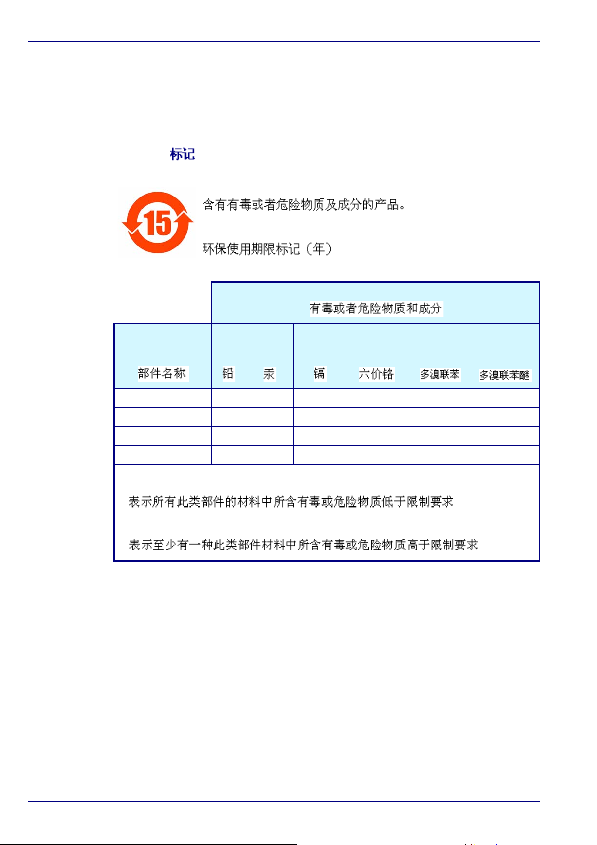
Restriction of Hazardous Substances
Note:
The following only applies to exports of the product into the People’s Republic of China.
Marking
Products contain toxic or hazardous substances or elements.
Environment Protection Use Period Marking (years).
Toxic or Hazardous Substances and Elements
Important Information - 3654 Portable H2/N2 Analyzer
Hexavalent
Lead
Part Name
1184 Board X
1112 Analog Board X
Spacer X
External Connector X
O: Indicates that this toxic or hazardous substance contained in all homogeneous material for
this part is below the limit requirement
X: Indicates that this toxic or hazardous substance contained in at least one of the
homogeneous materials used for this part is above the limit requirement
(Pb)
Mercury
(Hg)
Cadmium
(Cd)
Chromium
(Cr VI)
Polybrom
Biphenyls
(PBB)
Polybrom
Diphenyls
(PBDE)
Page 7

3654 Portable H2/N2 Analyzer - Table of Contents 1 of 66
Operator Manual
ORBISPHERE
Table of Contents
1 Installation
1.1 What you have Received.....................................................................9
1.2 WIN3654 PC Program Installation.....................................................10
1.3 Atmospheric Pressure Equilibrium ....................................................10
1.4 Sensor Installation.............................................................................10
1.5 Purge Gas Connection ......................................................................11
1.6 Connections.......................................................................................11
1.6.1 External Power Supply (optional) ........................................11
1.6.2 Instrument - PC Connection ................................................11
1.7 Flow Chamber Installation.................................................................13
1.8 Installation Completion Check List ....................................................14
1.8.1 Power ..................................................................................14
1.8.2 Check the Purge Gas Supply ..............................................14
1.8.3 Instrument Clock Setting .....................................................14
1.8.4 Barometric Pressure Setting................................................14
1.8.5 Sensor Membrane...............................................................14
1.8.6 Flow Chamber .....................................................................15
2 Operating Instructions
2.1 Operating Controls ............................................................................17
2.2 Taking Measurements.......................................................................19
2.2.1 Select Gas Measurement Phase.........................................19
2.2.2 Measurement Mode.............................................................19
2.3 Storing Measurements In the Instrument ..........................................20
2.3.1 Automatic Data Acquisition..................................................20
2.3.2 Manual Data Acquisition......................................................21
2.3.3 Viewing Stored Measurements............................................22
2.4 Storing and Accessing Measurements From a Computer.................22
2.4.1 Downloading Stored Values ................................................22
2.4.2 Altering the Sampling Point Descriptions ............................23
2.4.3 Copying Values ...................................................................23
2.4.4 Saving Values......................................................................23
2.4.5 Printing Values ....................................................................24
2.4.6 Clearing Stored Values........................................................24
2.5 Monitoring Measurements In Real-Time ...........................................25
2.6 After Use and Storage.......................................................................26
3 Options Setup
3.1 Main Menu Basics .............................................................................27
3.2 Analyzer - PC Connection .................................................................29
3.3 Reviewing Instrument Configuration..................................................29
3.4 Configuring the Instrument ................................................................29
3.4.1 Gas Measurement Phase....................................................29
Page 8

2 of 66 Table of Contents - 3654 Portable H2/N2 Analyzer
Operator Manual
ORBISPHERE
3.4.2 Measurement Units..............................................................30
3.4.3 Membrane Selection............................................................31
3.4.4 Automatic Data Acquisition - Setting Sampling Intervals.....31
3.4.5 Calibration Medium..............................................................32
3.4.6 Locking Out the Instrument’s CAL Button............................32
3.4.7 Rolling Average....................................................................32
3.4.8 Automatic Shutdown............................................................33
3.4.9 Measurement Mode.............................................................33
4 Calibrations
4.1 Barometric Pressure Sensor Calibration ...........................................35
4.2 Sensor Calibration .............................................................................36
4.2.1 Calibration Setup .................................................................37
4.2.2 Calibration In H
4.2.3 Calibration In H
4.2.4 Calibrating In a Liquid H
or N2 at Atmospheric Pressure.................38
2
or N2 at Elevated Pressure.......................39
2
or N2 Solution..............................40
2
5 Accessories and Attachments
5.1 Model 32311 Flow Meter ...................................................................41
5.2 Model 32939 External Power Supply.................................................42
6 Maintenance and Troubleshooting
6.1 Power Supply.....................................................................................43
6.2 Sensor Maintenance..........................................................................43
6.2.1 Maintenance Schedule ........................................................43
6.2.2 Testing the Sensor Condition...............................................43
6.2.3 Mounting Dual Membranes..................................................44
6.3 Membrane Replacement ...................................................................44
6.3.1 Removing the Membrane.....................................................44
6.3.2 Installing the Membrane.......................................................45
6.4 Purge Gas Cylinder Refill ..................................................................48
6.4.1 N
6.4.2 CO
6.4.3 Filling the Purge Gas Cylinder .............................................49
6.5 Troubleshooting - Instrument.............................................................50
6.5.1 Serial Test............................................................................50
6.5.2 Keyboard Test .....................................................................50
6.5.3 Display Test .........................................................................51
6.5.4 Clock Settings......................................................................51
6.5.5 Analog Voltages View..........................................................52
6.5.6 Measurements View ............................................................52
6.6 Troubleshooting - Operation..............................................................53
6.6.1 Program Identification..........................................................53
6.6.2 Diagnostics Messages.........................................................53
6.6.3 Continuous Purge ................................................................53
6.6.4 Troubleshooting Table .........................................................54
Purge Gas.......................................................................48
2
Purge Gas....................................................................49
2
Page 9

3654 Portable H2/N2 Analyzer - Table of Contents 3 of 66
Operator Manual
ORBISPHERE
7 Specifications
7.1 Instrument Specifications ..................................................................55
7.2 Sensor Specifications........................................................................56
8 Part Lists
8.1 Instrument Configurations .................................................................59
8.2 TC Sensor and Parts on Configured System ....................................59
8.3 Analyzer Spare Parts.........................................................................59
8.4 Sensor Spare Parts ...........................................................................60
Appendix A: Glossary
A.1 Common Units...................................................................................61
A.2 Terms and Definitions........................................................................61
Page 10

4 of 66 Table of Contents - 3654 Portable H2/N2 Analyzer
Operator Manual
ORBISPHERE
Page 11

3654 Portable H2/N2 Analyzer - Manual Overview 5 of 66
Operator Manual
ORBISPHERE
WARNING
CAUTION:
Note:
Manual Overview
About this Manual
The information in this manual has been carefully checked and is believed to be
accurate. However, Hach Ultra assumes no responsibility for any inaccuracies that may
be contained in this manual. In no event will Hach Ultra be liable for direct, indirect,
special, incidental, or consequential damages resulting from any defect or omission in
this manual, even if advised of the possibility of such damages. In the interest of
continued product development, Hach Ultra reserves the right to make improvements in
this manual and the products it describes at any time, without notice or obligation.
Published in Europe.
Copyright © 2006 by Hach Ultra. All rights reserved. No part of the contents of this
manual may be reproduced or transmitted in any form or by any means without the
written permission of Hach Ultra.
Revision History
• Initial Release, November 1998, Orbisphere
• Revision A, April 2000, Orbisphere
• Revision B, July 2001, Orbisphere
• Revision C, July 2002, Orbisphere
• Revision D, October 2003, Hach Ultra Analytics
• Revision E, May 2004, Hach Ultra Analytics
• Revision F, February 2006, Hach Ultra
• Revision G, May 2007, Hach Ultra
• Revision H, July 2007, Hach Ultra
Safety Conventions
A warning is used to indicate a condition which, if not met, could cause serious personal
injury and/or death. Do not move beyond a warning until all conditions have been met.
A caution is used to indicate a condition which, if not met, could cause minor or
moderate personal injury and/or damage to the equipment. Do not move beyond a
caution until all conditions have been met.
A note is used to indicate important information or instructions that should be considered
before operating the equipment.
Page 12

6 of 66 Manual Overview - 3654 Portable H2/N2 Analyzer
Operator Manual
ORBISPHERE
Safety Precautions
Please read the entire manual before unpacking, setting up, or operating this instrument.
Pay particular attention to all warning and caution statements. Failure to do so could
result in serious injury to the operator or damage to the equipment.
To ensure the protection provided by this equipment is not impaired, do not use or install
this equipment in any manner other than that which is specified in this manual.
Safety Recommendations
For safe operation, it is imperative that these service instructions be read before use and
that the safety recommendations mentioned herein be scrupulously respected. If danger
warnings are not heeded to, serious material or bodily injury could occur.
Service and Repairs
None of the instrument’s components can be serviced by the user. Only personnel from
Hach Ultra or its approved representative(s) is (are) authorized to attempt repairs to the
system and only components formally approved by the manufacturer should be used.
Any attempt at repairing the instrument in contravention of these principles could cause
damage to the instrument and corporal injury to the person carrying out the repair. It
renders the warranty null and void and could compromise the correct working of the
instrument and the electrical integrity or the CE compliance of the instrument.
If you have any problems with installation, starting, or using the instrument please
contact the company that sold it to you. If this is not possible, or if the results of this
approach are not satisfactory, please contact the manufacturer’s Customer Service.
Page 13
3654 Portable H2/N2 Analyzer - Manual Overview 7 of 66
Operator Manual
ORBISPHERE
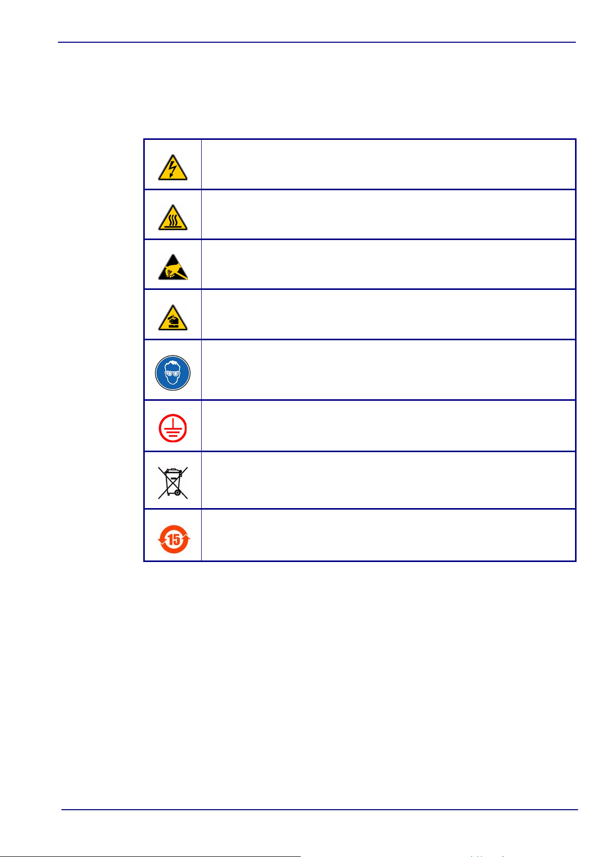
Precautionary Labels
Read all labels and tags attached to the instrument. Personal injury or damage to the
instrument could occur if not observed.
This symbol, when noted on a product enclosure or barrier, indicates that a risk of
electrical shock and/or electrocution exists and indicates that only individuals
qualified to work with hazardous voltages should open the enclosure or remove
the barrier.
This symbol, when noted on the product, indicates that the marked item can be hot
and should not be touched without care.
This symbol, when noted on the product, indicates the presence of devices
sensitive to electrostatic discharge and indicates that care must be taken to
prevent damage to them.
This symbol, when noted on the product, identifies a risk of chemical harm and
indicates that only individuals qualified and trained to work with chemicals should
handle chemicals or perform maintenance on chemical delivery systems
associated with the equipment.
This symbol, if noted on the product, indicates the need for protective eye wear.
This symbol, when noted on the product, identifies the location of the connection
for protective earth (ground).
Electrical equipment marked with this symbol may not be disposed of in European
public disposal systems. In conformity with European local and national
regulations, European electrical equipment users must now return old or
end-of-life equipment to the manufacturer for disposal at no charge to the user.
Products marked with this symbol indicates that the product contains toxic or
hazardous substances or elements. The number inside the symbol indicates the
environmental protection use period in years.
Acknowledgements
• Dacron, Delrin, Tedlar, Tefzel, and Viton are registered trademarks of DuPont.
• Halar is a registered trademark of Ausimont U.S.A., Inc.
• Hastelloy is a registered trademark of Haynes International.
• Kynar is a registered trademark of The Pennwalt Corporation.
• Monel is a registered trademark of IMCO Alloys International, Inc.
• Saran is a registered trademark of Dow Chemical Co.
• Swagelok is a registered trademark of Swagelok Co.
• Microsoft and Windows are registered trademarks of Microsoft Corporation.
Page 14

8 of 66 Manual Overview - 3654 Portable H2/N2 Analyzer
Operator Manual
ORBISPHERE
Page 15
3654 Portable H2/N2 Analyzer - Installation 9 of 66
Operator Manual
ORBISPHERE
1 Installation
This section provides necessary information to set up the instrument. If you have any
questions or experience any difficulties, do not hesitate to contact your Hach Ultra
representative regarding this procedure.
1.1 What you have Received
The ORBISPHERE 3654 portable analyzer includes the following major components:
• An instrument, model 3654/xxx, with keypad, display, and handle.
• A membrane-covered thermal conductivity (TC) sensor, either model 3127x for H
measurement or model 31570 for N
• A flow chamber, either model 32013A with flow adjustment valve for N
or model 32015 without flow adjustment valve for H
• A WIN3654 program on a CD with a PC communications cable.
Also included with your shipment are two C-type batteries, a recharge kit in a plastic case
containing materials to maintain your sensor and a model 32824A refilling hose to refill
the purge gas cylinder
measurement.
2
analyzers.
2
analyzers,
2
2
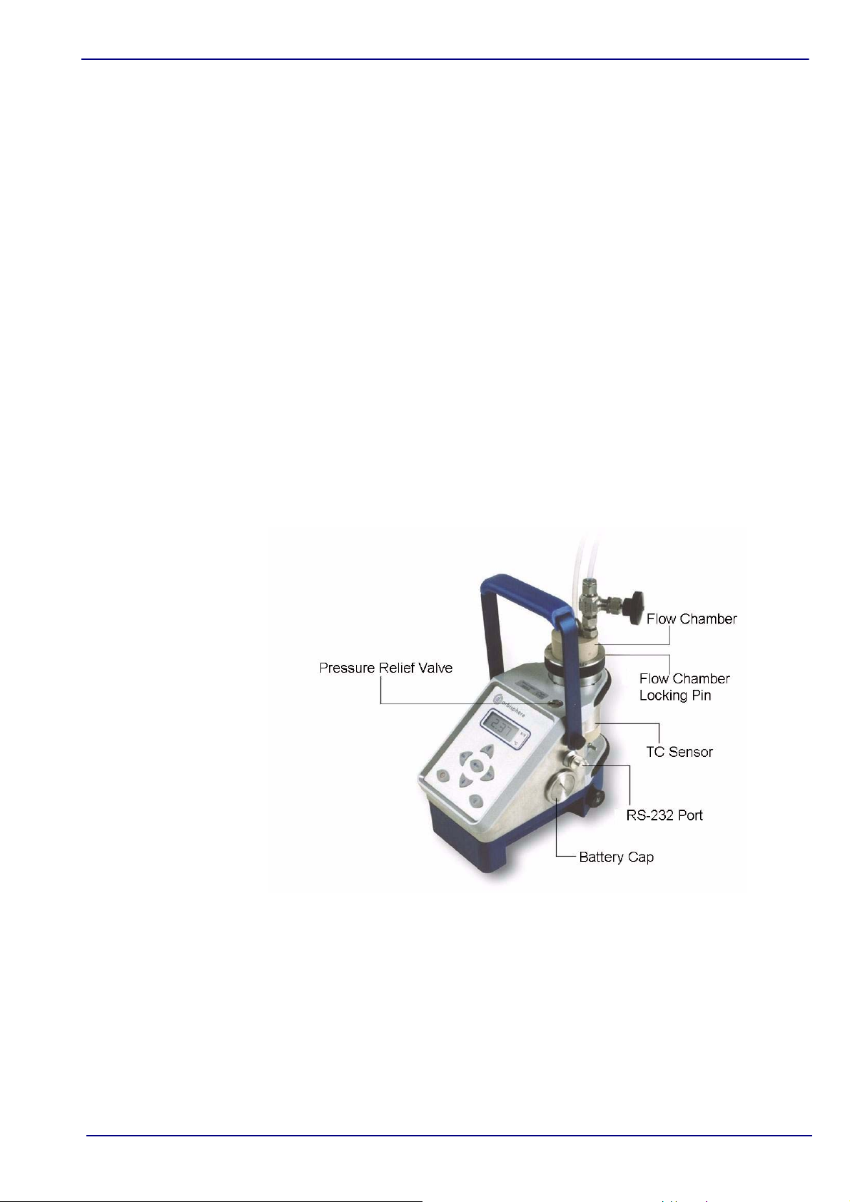
Fig 1-1:
ORBISPHERE 3654 Portable Analyzer
Locate the instrument close to the sample being analyzed, and to the Personal Computer
(PC) if one is being used. A LEMO-6 connector for RS-232 serial output to a PC is on the
right side of the instrument (see Fig 1-1 above).
Make sure you install a fully charged set of batteries, or connect the instrument to an
external power source (see “External Power Supply (optional)” on page 11), before
switching the instrument on and exposing the sensor’s membrane to any liquid.
Page 16
10 of 66 Installation - 3654 Portable H2/N2 Analyzer
Operator Manual
ORBISPHERE
1.2 WIN3654 PC Program Installation
Install the WIN3654 program onto the PC by inserting the accompanying CD into your
PC and running the SetUp program. Simply follow the on-screen instructions.
When finished, a new Windows Program Group labeled Orbisphere is created
containing the software and help files.
1.3 Atmospheric Pressure Equilibrium
As soon as you receive the instrument, it will be necessary to ensure the interior and
exterior of the instrument are both at the same atmospheric pressure. It is probable that
during shipment these pressures will become different.
To ensure the pressures are equal, simply press the relief valve switch located on the top
of the instrument (see Fig 1-1 on page 9) and hold it down for about 5 seconds before
releasing.
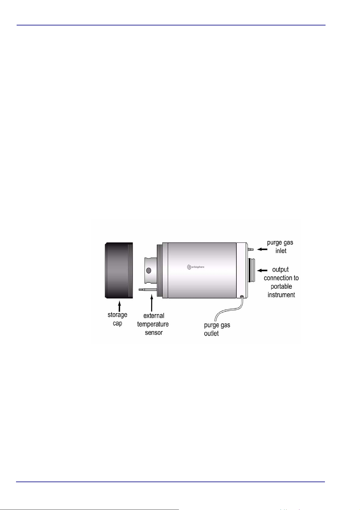
1.4 Sensor Installation
The TC sensor connects to the instrument base through a 10-pin LEMO connector. A
locking pin holds the sensor in place.
Fig 1-2:
Both the membrane-covered TC sensor and the flow chamber are shipped pre-installed
on the instrument. It will, however, be necessary to remove the flow chamber when
servicing the sensor. For details refer to “Sensor Maintenance” on page 43.
TC Sensor - Exploded View
Page 17

3654 Portable H2/N2 Analyzer - Installation 11 o f 6 6
Operator Manual
ORBISPHERE
Note:
Note:
Note:
1.5 Purge Gas Connection
It is critical that the TC sensor has a supply of purge gas running before operating the
system. The TC sensor, when exposed to a liquid sample, will become damaged if the
purge gas is not running.
CO
is used to purge the N2 sensor and N2 or CO2 is used to purge the H2 sensor. A
2
cylinder located at the bottom of the instrument supplies the purge gas. This cylinder is
refillable (see “Purge Gas Cylinder Refill” on page 48).
The TC sensor is purged cyclically. In measurement mode, a cycle consists of a 4
second purge followed by 16 seconds of measurement. When the instrument is in
standby, the purge time is the same, followed by a 17 minute delay. During the purge
time, the flow rate varies, depending on the pressure inside the cylinder. At least four
bubbles should exit from the purge gas exit during the purge time.
The purge gas input to the sensor uses a Tygon tube (4 mm outside/2 mm inside
diameter, 110 mm long) that attaches to the base of the sensor. Refer to the exploded
sensor diagram in Fig 1-2 on page 10.
The hole in the side and near the base of the sensor is the purge gas exit. To check the
purge gas flow rate, push the supplied nylon tubing into this hole, to its limit. To
disconnect it again, press on the ring surrounding the tube and pull out.
To check the purge gas flow rate, immerse the end of this tubing in water and switch on
the instrument. Gas should flow intermittently out of the tube.
During normal operation, and especially when the instrument is in standby mode,
ensure that the exit of the purge gas tube is exposed to the atmosphere and not in
contact with any liquid or hard surface.
1.6 Connections
1.6.1 External Power Supply (optional)
The instrument is usually powered by the batteries supplied. You can, however, power it
from an external power source using the model 32939 power supply adaptor as
described and illustrated in “Model 32939 External Power Supply” on page 42.
Connect the male LEMO-6 plug on the 32939, to the RS-232 connector on the right side
of the instrument. The female LEMO-6 plug can then be used to connect to your PC (if
required) using the standard RS-232 cable supplied with the instrument.
Plug the transformer into your mains power supply using the cable supplied.
If the external power supply is not clean, this may result in unstable measurements.
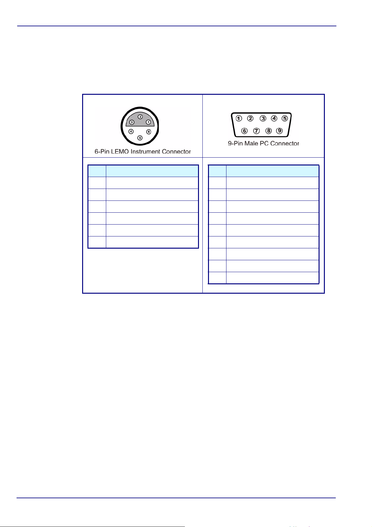
1.6.2 Instrument - PC Connection
An RS-232 cable is supplied with the instrument, with a 6-pin LEMO plug on one end and
a 9-pin D-Type plug on the other.
If you use an adapter for the connection to the PC, make sure it is designed for this
purpose and, thus, has all nine pins accessible. Some 25-to-9 pin adapters are supplied
for specific use, such as a mouse, and these may have only certain pins available.
Page 18
12 of 66 Installation - 3654 Portable H2/N2 Analyzer
Operator Manual
ORBISPHERE
Pin RS232 Signal
Pin 1 Transmitted data (TXD)
Pin 2 Received data (RXD)
Pin 3 Not Used
Pin 4 Not Used
Pin 5 Not Used
Pin 6 Ground
Pin Use
Pin 1 Not Used
Pin 2 RS-232 Transmitted Data (TXD)
Pin 3 RS-232 Received Data (RXD)
Pin 4 Not Used
Pin 5 Ground
Pin 6 Not Used
Pin 7 Not Used
Pin 8 Not Used
Pin 9 Not Used
It is not necessary to keep the PC connected to the instrument during measurement. This
connection is required for downloading stored measurements, real-time monitoring,
reviewing and changing configuration parameters and testing the instrument from the PC
(see “Troubleshooting - Instrument” on page 50 for details).
Fig 1-3:
Interface Box Connections
Page 19
3654 Portable H2/N2 Analyzer - Installation 13 of 66
Operator Manual
ORBISPHERE
CAUTION:
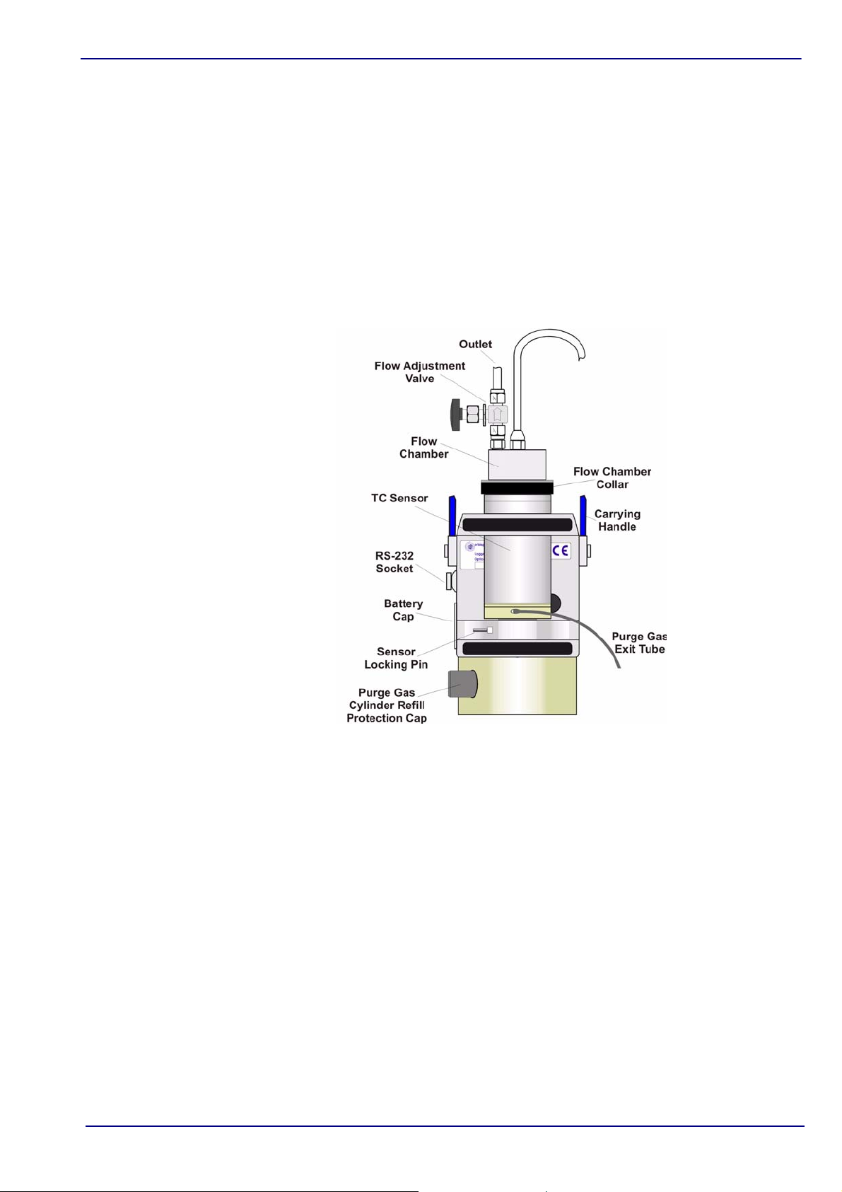
1.7 Flow Chamber Installation
The model 32013A or 32015 flow chamber allows the liquid or gaseous sample past the
TC and temperature sensors. The flow chamber attaches to the TC sensor with a
threaded collar and is sealed to the sensor with two O-rings (EPDM
∅4x1.5 mm).
At the top of the TC sensor is a thermistor to measure the sample temperature. Do not
bend or damage this component.
∅20x2 mm and NBR
Fig 1-4:
Flow Chamber 32013A
The flow chamber’s inlet and outlet use ¼-inch diameter transparent plastic tubing.
Connect by compression fittings to the sample source and to the drain, respectively.
You may also have received a model 32051 sample tube adapter to attach the flow
chamber inlet tubing to the sampling point (see “WIN3654 PC Program Installation” on
page 10).
Page 20

14 of 66 Installation - 3654 Portable H2/N2 Analyzer
Operator Manual
ORBISPHERE
Note:
1.8 Installation Completion Check List
1.8.1 Power
The instrument is designed to work on battery power or an external power supply.
If battery power should drop, a [LO BAT] warning appears in the instrument LCD's top
left corner, and they should be replaced.
If using an external power supply, ensure that this is clean, otherwise it may result in
unstable measurements.
1.8.2 Check the Purge Gas Supply
It is critical that the TC sensor has a supply of purge gas before operating the system.
The TC sensor, when exposed to a liquid sample, could be damaged if the instrument
purge gas cylinder is empty. At the same time, it is also critical that the instrument has a
power supply to ensure the purge gas is supplied to the sensor on a regular basis. The
system purges the sensor for 4 seconds every 20 seconds during normal measurement
mode, and every 17 minutes during standby mode.
A small, pressurized cylinder at the bottom of the instrument supplies purge gas to the
sensor. The purge gas required is:
•N
purge for H2 measurements.
2
•CO
Verify that the purge gas is flowing at more than four bubbles during the purge cycle, by
placing the purge gas exit tubing into water.
You must supply power constantly to the instrument, since it purges the sensor
continuously while power is on. When you put the instrument in standby, it still maintains
the purge gas supply to the sensor. Thus, make certain to supply battery or optional
external DC power constantly if the instrument is in standby and the sensor is exposed
to a sample. The batteries will provide about three weeks of power for purging while the
instrument is off.
purge for N2 or H2 measurements.
2
1.8.3 Instrument Clock Setting
If you use the instrument to store measurements for downloading to a PC, you should
verify the date and time settings of the instrument's internal clock, as described in “Clock
Settings” on page 51.
1.8.4 Barometric Pressure Setting
The internal barometric pressure sensor has been factory calibrated but should be
verified on-site with a precision certified barometer, and corrected if necessary. For
instructions on how to do this, please refer to “Barometric Pressure Sensor Calibration”
on page 35.
1.8.5 Sensor Membrane
Check that the membrane has been installed correctly, and is flat, tight, and wrinkle free.
Page 21

3654 Portable H2/N2 Analyzer - Installation 15 of 66
Operator Manual
ORBISPHERE
1.8.6 Flow Chamber
The flow chamber inlet and outlet should be free of any obstructions. The model 32013A
flow chamber, for dissolved N
The model 32015 flow chamber for H
Dissolved Gas Measurements
Adjust the sample flow rate using the needle valve on the exit. When analyzing
carbonated beverages, sufficient pressure must be provided to avoid degassing of the
beverage during its passage through the flow chamber. Check for the absence of
bubbles in the inlet tubing.
Gaseous Measurements
Place the outlet tubing in a container of water, ensuring that the flow chamber outlet is
unobstructed (on the 32013A flow chamber, open the outlet valve completely). Then,
adjust the inlet sample flow valve (main supply) to obtain one bubble per second at the
outlet.
measurements, has a flow adjustment valve on the outlet.
2
measurements has no valve.
2
Page 22

16 of 66 Installation - 3654 Portable H2/N2 Analyzer
Operator Manual
ORBISPHERE
Page 23

3654 Portable H2/N2 Analyzer - Operating Instructions 17 of 66
Operator Manual
ORBISPHERE
2 Operating Instructions
2.1 Operating Controls
The front panel of the instrument has a three-digit liquid crystal display (LCD). The LCD
includes a right-side marker to distinguish between gas concentration and temperature
display. This marker also indicates the measurement display units (g/kg, V/V, etc.)
depending on the instrument configuration. To the LCD's right is a label showing the
measurement units configured at the factory for your application.
Fig 2-1:
In addition to the controls indicated on the front panel, there is also a pressure relief valve
on top of the instrument (as indicated in Fig 1-1 on page 9). This button need only be
pressed as part of the installation procedures, and/or if pressure builds up inside the
instrument due to large temperature changes.
The panel keyboard has the following push-button controls:
Power switch. Turns instrument power on or places in standby. When
switched on, the instrument performs a series of start-up procedures
before switching to measurement mode
Places the instrument in measurement mode
Calibrates the analyzer against a reference sample. This button can
be locked out using the WIN3654 PC program
Instrument Front Panel
Page 24

18 of 66 Operating Instructions - 3654 Portable H2/N2 Analyzer
Operator Manual
ORBISPHERE
Stores a measurement value into memory
Backlights the LCD for approximately three minutes
Toggles between gas concentration and temperature measurement
displays in measurement mode, increases or decreases the storage
number during storage or memory view, or sets a calibration value
during calibration
You can access other instrument functions by pushing one of the following keys while
also pressing the power button:
Selects dissolved or gaseous measurement phase - see “Gas
Measurement Phase” on page 29
Start automatic data acquisition - see “Automatic Data Acquisition” on
page 20
Start memory storage view - see “Viewing Stored Measurements” on
page 22
Starts continuous purge mode - see “Continuous Purge” on page 53
Display program identification information
Once you have completed the installation and start-up procedures defined in
“Installation” on page 9, the analyzer can be operated independently, making
measurements as a portable hydrogen or nitrogen gas analyzer.
You may store these measurement values for later analysis via the WIN3654 program
(on your personal computer) or the memory view mode (on the instrument). The
WIN3654 program operation is described in detail throughout the manual, where
relevant.
Page 25

3654 Portable H2/N2 Analyzer - Operating Instructions 19 of 66
Operator Manual
ORBISPHERE
Note:
2.2 Taking Measurements
To start the analyzer, press the POWER switch (located bottom left of the keyboard).
When you turn power on, the instrument displays the software version number briefly,
and then starts a series of start-up tests. This process should take only a few minutes,
during which time a [tSt] message is displayed on the LCD. Once the tests are
completed, a clearing message [---] is displayed for a further sixty seconds before the
instrument switches automatically to measurement mode.
The start-up tests will be repeated until successful, or for a maximum of 15 minutes. If
the tests are still unsuccessful after 15 minutes, a [Err] message will be displayed and
the instrument locked. Turn the instrument off and retry the start-up procedures, but if
the problem persists, please contact your local Hach Ultra service representative for
assistance.
Measurement updates are displayed every 20 seconds, and it is normal for the rightmost digits to vary in reaction to slight variations in gas content. For accurate
measurements, the sensor's membrane must be at the same temperature as the sample
to be analyzed. If this not the case, allow some sample to pass through the flow chamber
for about 3 minutes before taking any measurements.
Minimum sample flow rates, measurement ranges and response times for the various
membranes are given in the tables in “Sensor Specifications” on page 56.
The LCD includes a right-side marker to distinguish between gas concentration
measurements and temperature. This marker also indicates the measurement display
units (k/kg, V/V, etc. depending on the instrument configuration).
To switch between gas measurement and temperature measurement, press the Up/
Down Arrow buttons. To illuminate the LCD for approximately three minutes, press the
Backlight button.
2.2.1 Select Gas Measurement Phase
Ensure the gas measurement phase is correct for this measurement. For details on
viewing the current setting, refer to “Reviewing Instrument Configuration” on page 29.
For details on changing this setting, refer to “Configuring the Instrument” on page 29.
2.2.2 Measurement Mode
You can set the measurement mode to normal or maximum. For details on how to do this
refer to “Measurement Mode” on page 33.
Maximum mode facilitates making measurements in bottles and cans. To search for a
maximum measurement value, press the MEAS button.
• The LCD first shows the message [run] for a few seconds, before displaying
measurement values.
• After a 60 second measurement cycle, the instrument searches for two
consecutive gas measurements with less than 2% difference. When this condition
occurs, the displayed value freezes on the LCD (indicated by a blinking display),
allowing you to note down or store the data.
The display remains frozen until you press the MEAS button to make a new
measurement, or you select normal measurement mode (as described in “Measurement
Mode” on page 33).
Page 26

20 of 66 Operating Instructions - 3654 Portable H2/N2 Analyzer
Operator Manual
ORBISPHERE
Note:
Note:
Note:
2.3 Storing Measurements In the Instrument
The analyzer will store up to 500 gas concentration and temperature measurement
values, labeled by numbers 0 through 499, along with the current date and time of each
measurement. You have the choice of acquiring this information manually or
automatically, as described below.
Do not put the instrument into standby while it is in the process of storing data,
otherwise the data values will be lost.
Before storing measurements, you should verify the date and time settings of the
instrument's internal clock, as described in “Clock Settings” on page 51.
2.3.1 Automatic Data Acquisition
When the instrument is used to automatically store measurement data, all buttons
except the POWER key are disabled. If enough time elapses to store all 500 values, the
instrument will return to normal measurement mode and the buttons re-enabled.
Before starting automatic measurement storage, first select the sampling rate desired
using the WIN3654 program (see “Automatic Data Acquisition - Setting Sampling
Intervals” on page 31).
1) Put the instrument into standby (by pressing
the POWER key)
2) Then hold down the STO button while
switching the instrument back ON. The LCD
displays the message Sto for about one
second
3) Normal gas concentration measurements are
displayed for about two minutes
4) After two minutes the instrument displays the
sample number (starting at 000), then the gas
concentration measurement value followed by
[---] to indicate the measurement is being
stored.
5) This storage sequence repeats automatically,
at the rate specified by the WIN3654 program
Sampling Rate menu. Values are stored
sequentially in sample numbers 000 through
499.
If you have not cleared previously stored values, the storage sequence automatically
overwrites the older values, as they are stored.
Page 27

3654 Portable H2/N2 Analyzer - Operating Instructions 21 of 66
Operator Manual
ORBISPHERE
Note:
Note:
Note:
To end automatic storage, put the instrument into standby (by pressing the POWER key)
while it is in normal measurement mode and not while it is in the process of automatically
storing data. Switching ON again without holding down the STO button returns the
instrument to measurement mode.
If you accidentally interrupt the automatic data storage by switching off the instrument
while it is in the process of storing a value, and you then attempt to download the stored
values by the WIN3654 program, you will get a Windows Checksum Error message,
and you will not be able to view the measurement data. If this happens, go back to the
instrument and manually log one more value (described in “Manual Data Acquisition” ).
You can then download your original set of values to your PC.
2.3.2 Manual Data Acquisition
You cannot store measurement data manually if the instrument has already been set up
to store the data automatically.
1) For the first measurement you wish to
store, press the STO button once to
display a sample number. The default
sample number is 000 (for first time
access), or the last used memory position
where data was stored, incremented by a
value of 1.
2) You can increase or decrease this
number by pressing the Up/Down Arrow
buttons within three seconds.
3) Should you decide at this point, not to
store this particular measurement, just
wait five seconds and the display returns
to measurement mode. You may also exit
this routine by pressing the MEAS button.
4) Press STO a second time, within five
seconds of the first. The instrument then
displays a brief clearing [---] message,
followed by the gas concentration
measurement value for about three
seconds (e.g. 8.56 in the flow diagram)
5) The [---] message is displayed as this
measurement value is stored
6) Repeat the above steps to store
additional measurements.
If you stored the first value as sample 001, the instrument automatically increases the
next storage location, and labels it sample 002. You can increase or decrease this
number by pressing the Up/Down Arrow buttons.
If you label a sample number the same as a previously stored measurement value, the
new measurement value overwrites the previously stored value.
Page 28

22 of 66 Operating Instructions - 3654 Portable H2/N2 Analyzer
Operator Manual
ORBISPHERE
2.3.3 Viewing Stored Measurements
1) Put the instrument into standby (by
pressing the POWER key)
2) Hold down the Up Arrow button
while switching the instrument back
ON. The LCD displays a sample
location number.
3) Scroll through the numbered
sample locations of all the stored
values using the Up Arrow and
Down Arrow buttons.
4) To view the actual gas
concentration measurement value
at a particular sample number,
press the STO button. The LCD
now displays the stored value for
that sample number.
5) Press STO a second time to return
to the next numbered location
display, to continue scrolling or
view another stored value.
To return to the measurement mode, put the instrument into standby and then turn back
ON again without holding down any additional buttons.
2.4 Storing and Accessing Measurements From a Computer
If you have made measurements and stored them in the analyzer, you should be ready
to bring them into the WIN3654 program for viewing, copying, saving and printing. See
also “Options Setup” on page 27 for additional information on the WIN3654 program.
2.4.1 Downloading Stored Values
To download the stored results from the analyzer to the PC, choose the DownLoad data
command from the Logger menu.
The DownLoad window presents a display of the stored measurements from the
instrument. The window displays five columns of data:
• Sample (sequence number of the sample)
• Conc (concentration of the measured gas)
• Date (date of the measurement)
• Time (time of the measurement)
• Sample Description
The descriptions can be modified for your applications using the procedures described
below.
Page 29

3654 Portable H2/N2 Analyzer - Operating Instructions 23 of 66
Operator Manual
ORBISPHERE
2.4.2 Altering the Sampling Point Descriptions
For help in identifying the locations of various sampling points that are stored by the
analyzer, you may choose the Sampling Point Description command from the Logger
menu to bring up the dialog box illustrated in Fig 2-2.
The measurement values to be placed in positions 0 through 499 (identified as Text 0,
Text 1... etc.) can be described however you wish. Double-click on a particular position
(or click Modify), then type a description of a maximum of 20 characters in the box as
shown (e.g. Tank 3). Choose OK when finished entering a description.
When you Close this box, your modifications will be saved, and will appear in the
Sample Description column for the next downloaded list. These descriptions can be
modified again later as your requirements change.
2.4.3 Copying Values
To copy the results to the Windows Clipboard, so that the data can be pasted into a
spreadsheet, word processor or other Windows program that accepts tabular text
information, choose the Clipboard command from the Export menu.
2.4.4 Saving Values
To save this list of measurements as a text (.txt) file, capable of being recalled by the
WIN3654 program or imported as a file into other Windows programs, choose the Save
As command from the File menu. A dialog box appears, with a space to fill in with an
eight-letter name. (The program automatically attaches a .txt suffix to these files.) If you
have saved previous files, a grayed-out list of these names appears as well.
Fig 2-2:
Sampling Point Descriptions
Typical to Windows programs, Directories and Drives boxes can be used to locate
other storage devices on which to store your data.
Page 30

24 of 66 Operating Instructions - 3654 Portable H2/N2 Analyzer
Operator Manual
ORBISPHERE
Note:
2.4.5 Printing Values
To place this list of measurements into a tabular
format and send it to the Windows printer, choose
the Print command from the File menu.
The program asks you to enter Title and Author
information as illustrated left. The Date is fixed by
your operating system.
The resulting printed list will include this information
on each page.
2.4.6 Clearing Stored Values
To clear all the values stored in the analyzer via the WIN3654 program, choose the Clear
Data command from the Logger menu. Since this action will clear the storage memory
of the instrument, a warning appears first as shown left in Fig 2-3.
Fig 2-3: Clear Stored Values
Choose OK to bring up the next dialog box to confirm the clear action.
Choose Clear to start the memory clear operation. A message, Reset should be
completed appears in this box when the task is finished.
You can accomplish the same thing passively, by simply allowing the analyzer to
overwrite a set of stored values with new ones.
Page 31

3654 Portable H2/N2 Analyzer - Operating Instructions 25 of 66
Operator Manual
ORBISPHERE
2.5 Monitoring Measurements In Real-Time
You may wish to analyze a particular sampling point via the WIN3654 program's
Monitoring menu. To use this Monitoring chart, the analyzer must be connected to your
PC.
Choose Monitoring from the WIN3654 menu to bring up a chart display like the one
illustrated in Fig 2-4.
Fig 2-4:
Real-Time Monitoring
The Monitoring chart shows the gas concentration (in blue), temperature (in red), and
pressure (in green) as the sample is being measured by the 3654 instrument. The chart
is updated directly from instrument measurements, at a rate determined by the time
scale set in the TIMEBASE box at the lower right corner of the chart.
Click the TIMEBASE up/down pointers to change the time scale of the divisions of the
chart. Each division mark along the baseline (1, 2, ...10) can be made to represent from
30 seconds to 2½ hours, providing from 5 minutes to 25 hours of continuously displayed
samples. The chart updating rate is determined by the time scale selected, as shown in
Table 2-1, “Chart Updating Rate,” on page 25.
Table 2-1: Chart Updating Rate
Timebase Updating Rate* Maximum Samples (10 divisions)
30 Seconds/Division 5 Seconds/Sample 60
1 Minute/Division 5 Seconds/Sample 120
10 Minutes/Division 5 Seconds/Sample 1,200
30 Minutes/Division 9 Seconds/Sample 2,000
1 Hour/Division 18 Seconds/Sample 2,000
2.5 Hours/Division 45 Seconds/Sample 2,000
*This chart's updating rate is independent from the acquisition rate (see
“Automatic Data Acquisition - Setting Sampling Intervals” on page 31).
Page 32

26 of 66 Operating Instructions - 3654 Portable H2/N2 Analyzer
Operator Manual
ORBISPHERE
Click on the Continuous box, in the lower right corner, to enable or disable continuous
charting. When this box is checked, the chart scrolls continuously after reaching the 10
division, and the oldest samples are lost off the left of the chart. When Continuous is not
checked, the chart stops displaying new results after reaching the 10 division, and all
subsequent measurements are lost.
Click the up/down pointers for each measurement variable (GAS, TEMPERATURE and
PRESSURE) at the right of the chart to change the scaling of that value on the chart. The
display of each measurement variable may be turned on or off by choosing the
appropriate On or Off switch at the right of the chart.
If your measurements do not chart properly, try using a higher or lower value scale or
time base than the one displayed. Adjust these scale factors befo re starting the
monitoring operation.
A running display of latest sample Gas, Temperature and Pressure is also shown in the
bottom-right corner of the chart.
Use the buttons at the bottom of the chart to control real-time monitoring. Choose Go to
clear the chart and start real-time monitoring display, Stop to stop real-time monitoring
and Copy to copy the data from the chart as text information to the Windows Clipboard.
This information can be pasted from the clipboard into any Windows application, such as
a spreadsheet or word processor. See Table 2-1, “Chart Updating Rate,” on page 25 for
the maximum number of samples that can be copied for each chart time scale.
Finally, choose Close to close the Monitoring window.
2.6 After Use and Storage
You can power off the instrument without losing setup or calibration parameters.
If measuring in a liquid sample, run clean warm water through the flow chamber after
each series of measurements to prevent passages from clogging, and to keep the
membrane clean.
The sensor must be continuously purged, if it is wet, to prevent any damage to the
thermal conductivity sensing element. The instrument handles this automatically, even if
switched off during short periods (for example overnight), provided it has a power supply
(fully charged batteries or an external power supply) and a fully loaded purge gas
cylinder.
If you expect not to use your sensor for several days, flush all sample liquid out of the
flow chamber, remove the flow chamber and dry it with a soft tissue. Dry the sensor head
surface with a clean soft tissue to ensure no liquid is on the membrane or protection cap.
Once dry, replace the sensor’s storage cap to protect it from any accidental damage.
Store with a silica bag to prevent any humidity build-up.
Page 33

3654 Portable H2/N2 Analyzer - Options Setup 27 of 66
Operator Manual
ORBISPHERE
3 Options Setup
The WIN3654 program is an integral part of the analyzer. Running under Microsoft
Windows®, it permits you to list and analyze up to 500 stored measurement values. The
program also includes a special monitoring feature, which lets your computer act as a
chart recorder, and enables a hardware test to ensure that the system is in good working
order.
3.1 Main Menu Basics
When you start the program, it displays the Main Menu, which automatically maximizes
on opening and appears as follows:
Throughout the WIN3654 program menus, you will see shortcut keys (such as Ctrl+P, to
print a list of stored values). As you become familiar with the program, you may choose
these keystroke commands for faster operation.
File, shown below, serves typical Windows file management needs.
WIN3654 data files can be opened, saved under a different name, closed, or printed. You
can also exit the program.
The Logger menu appears as follows. Here you can download measurement values
from the instrument, make modifications to the sample list that can be used to identify
sampling point locations, or clear the instrument's stored values.
Page 34

28 of 66 Options Setup - 3654 Portable H2/N2 Analyzer
Operator Manual
ORBISPHERE
Note:
Export places your information into the Windows Clipboard, so that it can be pasted
directly into other Windows programs. This is especially useful when working with
spreadsheet or word processing programs.
The Monitoring menu creates a running chart of real-time measurements (see
“Monitoring Measurements In Real-Time” on page 25). These values can also be saved
to the Windows Clipboard.
The Configuration menu lets you see how your system has been configured for your
application. You may use this menu to change the configuration parameters should your
application needs change.
The Troubleshooting menu includes a series of tests, allows you to set the clock, and
enables a barometric pressure calibration routine.
Finally, the Help menu gives access to the Help file and displays the identification of the
WIN3654 program (version number and copyright date).
If the PC operating system is Windows Vista®, it may be necessary to download the
Winhlp32.exe file from the Microsoft web site.
Page 35

3654 Portable H2/N2 Analyzer - Options Setup 29 of 66
Operator Manual
ORBISPHERE
3.2 Analyzer - PC Connection
For the hardware connection of the analyzer to a PC, see “Instrument - PC Connection”
on page 11.
The Configuration, Serial port menu lets you choose one of four serial communication
ports, as follows:
Usually, COM1 is used to connect to a mouse, so
try COM2 first. You may find that a separate
program supplied with your PC may be necessary
to activate this port.
Click on OK to activate the selected port. If the port
you have selected here is available, the WIN3654
program will return to the main menu. Otherwise,
you will see an RS232 ERRORS message advising
you to select another port.
3.3 Reviewing Instrument Configuration
To review if the analyzer is set up as expected, choose the Configuration,
Configuration view command. You will see a window similar to the following:
3.4 Configuring the Instrument
The ORBISPHERE 3654 analyzer can be readily configured for your application using
the following commands in the Configuration menu. The instrument must be connected
to your PC and powered on, in order to change any configuration parameters.
Some of the parameters
listed, can be changed by
using the WIN3654
program.
However, should you see
any unexpected items listed
on your screen that you
cannot correct, contact your
Hach Ultra representative.
3.4.1 Gas Measurement Phase
The instrument can measure N2 or H2 in either a liquid or
a gaseous sample, but you must select which gas phase
to use.
Choosing the WIN3654 program's Configuration, Gas
Phase menu lets you select the gas measurement phase.
Page 36

30 of 66 Options Setup - 3654 Portable H2/N2 Analyzer
Operator Manual
ORBISPHERE
The gas measurement phase can also be selected from the instrument keyboard as
follows:
1) Switch the instrument power OFF
2) Switch the instrument on by holding down the
CAL button and then pressing the POWER button
while still pressing the CAL button
3) The instrument display will first show PHA before
switching to either dIS for dissolved or gAS for
gaseous measurements
4) Use the Up/Down Arrow buttons to change the
gas phase to your choice
5) Press the MEAS button to save the selected gas
measurement phase. The instrument then goes to
measurement mode
3.4.2 Measurement Units
Using this dialog box, you can select:
• The Gas units in which gas concentrations are to be displayed
For dissolved measurements:
g/kg, % (by weight), V/V, cc/kg, ml/l, ppm/ppb, ppm or mg/100ml
For gaseous measurements:
%/ppm (by volume), % (by volume), kPa/Pa, kPa, bar/mbar, bar,
bar20/mbar20 or bar20
Choose the Configuration, Units menu to
select gas measurement units, temperature
measurement units, and the liquid medium in
which you are measuring.
You may change the LCD label on the
instrument to match the new units selected.
Different LCD labels are supplied with the
recharge kit.
• The Liquid medium for dissolved gas concentration measurements
Water, Beer or Cola
• The Temperature units for display
°C or °F
Page 37

3654 Portable H2/N2 Analyzer - Options Setup 31 of 66
Operator Manual
ORBISPHERE
Note:
Note:
3.4.3 Membrane Selection
You may find it necessary to use a different type of membrane for different applications.
Naturally, with any membrane change, you will need to re-calibrate (see also “Sensor
Calibration” on page 36).
You should also consider the changes in required flow rates and response times, which
are listed in “Sensor Specifications” on page 56.
To re-configure the analyzer, choose Configuration, Membrane to bring up the box
which reveals the membrane models available.
Membrane 29561A is available for any gas measurement.
Membranes 2935A and 2952A are available for H
measurement only.
Choose OK when the desired membrane is selected.
2
Only those membranes applicable to your system can be selected. All other membranes
are grayed out.
3.4.4 Automatic Data Acquisition - Setting Sampling Intervals
The analyzer can perform as a standalone data acquisition device, automatically
recording gas measurements with the date and time, and storing up to 500 of these
values. Choosing the WIN3654 program's Configuration, Sampling Rate menu lets
you select time intervals (acquisition rate) for this storage capability.
Use the slide bar to view and select a sampling rate, from
15 seconds to 1 hour. The selected rate is shown in the
Acquisition rate window.
Click OK to save this rate. Once your choice is made, the
analyzer can be used independently of the WIN3654
program for data acquisition, as described in “Automatic
Data Acquisition” on page 20.
The Acquisition rate set via this menu is independent from the monitoring chart updating
rate described in “Monitoring Measurements In Real-Time” on page 25. The sampling
rate menu applies only to automatic data acquisition, while the chart updating rate is
used only for displaying real-time results via the monitoring chart.
Page 38

32 of 66 Options Setup - 3654 Portable H2/N2 Analyzer
Operator Manual
ORBISPHERE
Note:
3.4.5 Calibration Medium
You can use the Configuration, Calibration medium command to select how the
sensor is to be calibrated.
Choose either in pure H2 or N2 gas at
atmospheric pressure or in a liquid or
gaseous solution at a known concentration
of gas.
Choose OK when the desired medium is
selected.
You can create a solution having a known H2 or N2 concentration by dissolving H2 or N2
in water at a measured temperature and pressure. Hach Ultra can provide equipment
for generating such a solution. Alternatively, you can analyze a carbonated beverage
independently by other acceptable means.
3.4.6 Locking Out the Instrument’s CAL Button
You can use the Configuration, Sensor Calibratio n
Status menu to prevent an accidental sensor re-
calibration from the instrument keyboard.
Choose Disabled to lock out the keyboard CAL button.
To unlock this capability, choose Enabled. Choose OK
when the desired mode is selected.
3.4.7 Rolling Average
Choose Rolling Average Status from the Configuration
menu to enable or disable the averaging of gas
concentration measurements.
To enable averaging on three successive gas
measurements, choose Enable. Choose Disable to
disable rolling average.
Page 39

3654 Portable H2/N2 Analyzer - Options Setup 33 of 66
Operator Manual
ORBISPHERE
3.4.8 Automatic Shutdown
Choose Automatic Shutdown Status from the Configuration
menu to activate the Automatic Shutdown feature.
If you select Enable, the instrument switches off automatically
after 10 minutes of inactivity, thereby economizing battery
power.
3.4.9 Measurement Mode
Choose Measurement Mode from the Configuratio n menu to enable maximum
measurement mode for sampling in bottles and cans.
In Maximum measurement mode, the
instrument searches for two consecutive
measurements with less than a 2%
difference, as also described in
“Measurement Mode” on page 19.
When this occurs, the display is frozen and you may store the data. The instrument
remains in this mode until you select Normal measurement mode.
Page 40

34 of 66 Options Setup - 3654 Portable H2/N2 Analyzer
Operator Manual
ORBISPHERE
Page 41

3654 Portable H2/N2 Analyzer - Calibrations 35 of 66
Operator Manual
ORBISPHERE
4 Calibrations
4.1 Barometric Pressure Sensor Calibration
You must have access to an accurate barometer to calibrate the instrument's internal
barometric pressure sensor. This is done using the PC WIN3654 program.
Choose T roubleshooting, Press ure
Calibration and a message will warn that
the current calibration will be lost.
Choose OK to continue.
The calibration procedure then displays a Pressure Calibration dialog box (as
illustrated in Fig 4-1). The Measured Pressure value shows the current instrument
pressure reading.
Fig 4-1:
Enter the current atmospheric pressure, in mbars, in the Calibration Pressure entry
box. Choose Calibrate to direct the instrument to read and display the Measured
Pressure using this calibration value.
Choose Quit when you are satisfied with the pressure calibration to return to normal
operation.
Pressure Calibration Screens 2 & 3
Page 42

36 of 66 Calibrations - 3654 Portable H2/N2 Analyzer
Operator Manual
ORBISPHERE
4.2 Sensor Calibration
The TC sensor can be calibrated in pure H2 or N2 gas at atmospheric or elevated
pressure. The following table gives information regarding the different methods.
Table 4-1:
Calibration Method Time Benefits Drawbacks Reference
Gas at atmospheric
pressure
Gas at elevated
pressure (2-3 bar)
Sensor Calibration Information
5 min Quick and easy
Higher accuracy than
10 min
atmospheric method.
Validation of the
sensor linearity
Less accurate than
other methods
Requires a certified
pressure gauge
Gas with known
purity, certified
barometer
Certified pressure
gauge
Before calibrating check that the sensor membrane surface is tight, smooth and wrinkle
free. Select the gas measurement phase for calibration (for full details see “Gas
Measurement Phase” on page 29). Next, select the calibration medium using the
WIN3654 program (see “Calibration Medium” on page 32).
Ensure that normal measurement mode is selected in the Measurement Mode menu of
the WIN3654 program (see “Measurement Mode” on page 33).
Calibration must only be carried out once the TC sensor is giving a stable measurement.
Expose the membrane to the calibration sample until this stable reading is obtained. This
usually takes about 5 minutes.
For calibration it is important that the sensor's membrane is at the same temperature as
the calibration sample. Therefore, allow some sample to pass through the flow chamber
for 3 minutes before calibrating.
Page 43

3654 Portable H2/N2 Analyzer - Calibrations 37 of 66
Operator Manual
ORBISPHERE
4.2.1 Calibration Setup
Ensure that the purge gas is flowing at the recommended rate through the sensor by
placing the purge gas exit tubing into water. This rate should be more than four bubbles
during the purge which lasts for 4 seconds.
This purge cycle is repeated every 20 seconds.
Fig 4-2:
Calibration Setup Diagram
The calibration procedure requires a source of pure gas (regulated by a pressure valve)
connected to the central entry port of the flow chamber, an accurate pressure gauge
(better than
± 2%) at the exit of the flow chamber, a needle valve to control the flow on
exit, and a beaker of water to monitor the gas flow. Fig 4-2 above illustrates the
calibration setup.
Page 44

38 of 66 Calibrations - 3654 Portable H2/N2 Analyzer
Operator Manual
ORBISPHERE
WARNING
4.2.2 Calibration In H2 or N2 at Atmospheric Pressure
The sensor can be calibrated in pure H2 or N2 gas at atmospheric pressure.
Handle H2 gas with great care. It is extremely flammable and explosive.
To ensure that the flow chamber and sensor components are dry, remove and blow dry
the flow chamber. Dry the sensor head surface with a clean soft tissue.
The analyzer uses an internal barometric pressure sensor during this calibration. First
check that the pressure sensor is correct and does not need recalibrating. If it does need
to be recalibrated then follow the instructions in “Barometric Pressure Sensor
Calibration” on page 35 before attempting this calibration.
1) Set the gas measurement phase to Gaseous and set the calibration medium to
In measured pure gas at atmospheric pressure (as detailed in “Calibration
Medium” on page 32).
2) Connect a source of pure H
illustrated in Fig 4-2 on page 37, and adjust the gas flow to one bubble per
second when the exit tube is immersed in water.
3) Press the CAL button. Remember, this button may have been locked out to
prevent an accidental reset (see “Locking Out the Instrument’s CAL Button” on
page 32 for details).
or N2 gas to the inlet of the flow chamber, as
2
4) Press the CAL button. Remember, this
button may have been locked out to
prevent an accidental reset (see “Locking
Out the Instrument’s CAL Button” on
page 32 for details).
5) A brief clearing message [---]
appears.
6) Press CAL again within a 3 second
period.
If the instrument makes two consecutive
measurements with less than 1%
difference, it calibrates against this
stabilized value. The LCD then displays
the message [CAL] to indicate
calibration has been successfully
completed
If the calibration does not complete, the
LCD displays the message [Err]. The
reason for this calibration error is either
that the measured gas partial pressure is
under 5 mbar, or that a wrong instrument
key was pressed during the calibration
steps.
Page 45

3654 Portable H2/N2 Analyzer - Calibrations 39 of 66
Operator Manual
ORBISPHERE
WARNING
4.2.3 Calibration In H2 or N2 at Elevated Pressure
The sensor can be calibrated in pure H2 or N2 gas at an elevated pressure. This method
requires an accurate pressure gauge connected to the exit of the flow chamber.
Handle H2 gas with great care. It is extremely flammable and explosive.
When calibrating in gas phase, the flow chamber and sensor head must be dry.To
ensure that the flow chamber and sensor components are dry, remove and dry them with
a clean soft tissue.
1) Set the gas measurement phase to Gaseous and set the calibration medium to
In a liquid or a gaseous sample at known concentration (as detailed in
“Calibration Medium” on page 32).
2) Connect a source of pure H
illustrated in Fig 4-2 on page 37, and adjust the gas flow exiting from the flow
chamber to be in the range of 1 to 5 bar (it is best to use a pressure close to the
application conditions).
or N2 gas to the inlet of the flow chamber, as
2
3) Press the CAL button. Remember, this
button may have been locked out to
prevent an accidental reset (see “Locking
Out the Instrument’s CAL Button” on
page 32 for details).
4) A brief clearing message [---]
appears.
5) Press CAL again within a 3 second
period. The instrument then displays the
absolute pressure of calibration gas (i.e.
gauge pressure plus atmospheric
pressure).
6) Modify this reading using the Up/Down
Arrow keys until the displayed pressure
agrees with that of the gauge plus
atmospheric pressure.
7) Press CAL again.
If the instrument makes two consecutive
measurements with less than 1%
difference, it calibrates against this
stabilized value. The LCD then displays
the message [CAL] to indicate
calibration has been successfully
completed
If the calibration does not complete, the
LCD displays the message [Err]. The
reason for this calibration error is either
that the measured gas partial pressure is
under 5 mbar, or that a wrong instrument
key was pressed during the calibration
steps.
Page 46

40 of 66 Calibrations - 3654 Portable H2/N2 Analyzer
Operator Manual
ORBISPHERE
Note:
4.2.4 Calibrating In a Liquid H2 or N2 Solution
The sensor can be calibrated in a standard liquid solution that has a known concentration
or N
of H
2
. You can create a solution with a known concentration by dissolving H
2
in water at a measured temperature and pressure. Alternatively, analyze a carbonated
beverage independently by some acceptable means.
1) Set the gas measurement phase to
Dissolved and set the calibration
medium to In a liquid or a gaseous
sample at known concentration (as
detailed in “Calibration Medium” on
page 32).
2) Press the CAL button. Remember, this
button may have been locked out to
prevent an accidental reset (see “Locking
Out the Instrument’s CAL Button” on
page 32 for details).
3) A brief clearing [---] message
appears.
4) Press CAL again within a 3 second
period. The instrument then displays the
concentration of H
or N2, based on the
2
last value of the calibration coefficient.
5) Modify this reading using the Up/Down
Arrow keys until the displayed
concentration agrees with that of the
calibration solution.
6) Press CAL again.
7) Start the flow of the standard (calibration)
solution through the flow chamber. Adjust
the flow until the liquid is foam-free. The
flow rate should be a minimum of 150 ml/
min and be stable.
or N
2
2
A flow rate lower that 150 ml/min can be used for the calibration, but you must ensure
that all measurements made after the calibration are made at exactly the same flow rate
as is used for the calibration. To ensure accurate results it is recommended to use a
model 32311 Flow Meter as described in “Model 32311 Flow Meter” on page 41.
If the instrument makes two consecutive measurements with less than 1% difference, it
calibrates against this stabilized value. The LCD then displays the message [CAL] to
indicate calibration has been successfully completed
If the calibration does not complete, the LCD displays the message [Err]. The reason
for this calibration error is either that the measured gas partial pressure is under 5 mbar,
or that a wrong instrument key was pressed during the calibration steps.
Page 47

3654 Portable H2/N2 Analyzer - Accessories and Attachments 41 of 66
Operator Manual
ORBISPHERE
5 Accessories and Attachments
5.1 Model 32311 Flow Meter
A flow meter is available as an option, to attach to the top of the flow chamber, instead of
the flow rate adjustment valve usually supplied. This can be used to set an accurate flow
rate of the sample. This is especially useful with small volume packages such as small
cans and bottles.
This flow meter simply replaces the standard adjustment valve, as illustrated in Fig 5-1
below.
Fig 5-1:
If using this flow meter option, you must ensure that you first recalibrate the instrument
with the flow meter attached before you take any measurements. In addition, any
measurements made must be made using exactly the same flow rate setting as used for
the calibration.
The recommended flow rate should be set at 50%, though a minimum flow rate (for small
volume packages) of 30% can be used. To set the flow rate, adjust the knob at the top of
the flow meter until the center point of the bead indicates the desired flow rate.
Standard Adjustment Valve (left) and Flow Meter (right)
Page 48

42 of 66 Accessories and Attachments - 3654 Portable H2/N2 Analyzer
Operator Manual
ORBISPHERE
5.2 Model 32939 External Power Supply
Provided you have a clean external power supply, you can connect the power directly to
the instrument, using this accessory, via the RS-232 port on the instrument (as illustrated
in Fig 1-1 on page 9).
Fig 5-2:
Model 32939 Power Supply
The male LEMO-6 (to the right on the illustration above) attaches directly to the
instrument. The female LEMO-6 (to the left on the illustration above) can be used to
attach the instrument to your PC. The other connection is to the transformer (illustrated
to the top) which in turn is connected directly to your power supply.
Page 49

3654 Portable H2/N2 Analyzer - Maintenance and Troubleshooting 43 of 66
Operator Manual
ORBISPHERE
Note:
CAUTION:
6 Maintenance and Troubleshooting
6.1 Power Supply
It is important to maintain power to the instrument at all times, (either batteries or an
external power supply) to ensure the sensor is continually purged and so prevent
damage to the TC sensor chip.
If the 3654 instrument is operating on battery power (two standard C-type cells), and the
battery power should drop, a
LCD's top left corner.
To install the batteries, unscrew the battery cap (on the right side of the instrument) with
the tool provided in the recharge kit, or with a coin or flat bladed screwdriver. Place the
cells lengthwise into the battery compartment (positive end first), and then replace the
cap. Refer to the diagram on the back of the instrument.
Rechargeable nickel-cadmium batteries may be used. Expect about 15 hours of
autonomy in continuous operational use, or 3 weeks in standby (with purge gas
supplied). Alkaline batteries provide the longest continuous use though mercury-free
batteries are available that present less of a disposal problem.
[LO BAT] warning message is displayed in the instrument
Make sure that a fully charged (or fresh) set of batteries is installed before switching on
the instrument.
6.2 Sensor Maintenance
6.2.1 Maintenance Schedule
Sensor maintenance includes membrane replacement and external cleaning to restore
the original sensor sensitivity. This means low running costs and down time reduced to
a minimum.
The membrane needs to be replaced once or twice a year depending on application
conditions. This can be tailored accordingly.
If you are not familiar with Orbisphere sensor servicing, your Hach Ultra representative
will be glad to assist you
6.2.2 Testing the Sensor Condition
Periodically, visually inspect the sensor head for any deposits. Rinse it under clean tap
water, and dry with a clean tissue.
To verify the sensor, check measurements vs. a known standard sample value:
• If reading deviation is ±1% of the expected value, no action needs to be taken.
• If deviation exceeds ± 1%, perform a new calibration.
• If deviation exceeds 10% of the original values, replace the membrane.
Carry out the maintenance in a clean dry place in order to avoid damaging the sensor's
precision components, and also to prevent water or humidity from getting into the
sensor.
Page 50

44 of 66 Maintenance and Troubleshooting - 3654 Portable H2/N2 Analyzer
Operator Manual
ORBISPHERE
Note:
CAUTION:
6.2.3 Mounting Dual Membranes
In order to prevent unwanted stretching of the membrane on a hydrogen sensor it is
recommended to simultaneously mount a support membrane beneath the primary
membrane.
The primary membrane, or top membrane, determines the rate at which the H
enters the measurement chamber of the sensor. The secondary membrane, or support
membrane on the bottom, is extremely permeable and is installed to stabilize the position
of the primary membrane.
Two primary membrane types are used for H
application:
• 29561A - used for waste gas, off gas and dH
• 2952A - used for dH
The support or secondary membrane for all H
As two membranes will be mounted together, the mounting ring used must be part
number 29229 which is designed for a thickness of 50 microns or more. Mounting ring
part number 29228 is designed for a single membrane and should not be used for
mounting dual membranes.
6.3 Membrane Replacement
After replacing a membrane, the sensor must always be re-calibrated. Allow the sensor
to settle for 30 minutes in measurement phase to allow measurements to stabilize,
before performing the sensor calibration.
measurement depending on the type of
2
in a boiling water reactor
2
in reactor cooling systems of a pressurized water reactor.
2
measurement applications is the 29562A.
2
gas
2
6.3.1 Removing the Membrane
It is recommended to leave the sensor in place in the instrument when changing the
membrane. It is not necessary to remove it.
To remove the membrane, follow the steps below:
First remove the flow chamber from the sensor by turning the flow chamber locking pin
(see position in Fig 1-1 on page 9) counter-clockwise and gently lifting the flow chamber
off the sensor.
A thermistor at the top of the sensor (illustrated
right) is used to measure the sample temperature.
Do not bend or damage this component by trying to
twist the flow chamber off the sensor.
Page 51

3654 Portable H2/N2 Analyzer - Maintenance and Troubleshooting 45 of 66
Operator Manual
ORBISPHERE
CAUTION:
Note:
Note:
Note:
Unscrew the protection cap, using the tool provided in the
maintenance kit.
Never remove the protection cap, unless you plan to
replace the membrane.
Pull up the membrane holding ring with the tool provided
in the maintenance kit.
Remove the old membrane and discard it.
6.3.2 Installing the Membrane
To install the new membrane, follow the steps below:
The membrane mounting surface must be clean and
even (on top of the sensor, where the membrane and
sensor have contact).
Replace the membrane O-ring on the sensor head with a
new one.
The 29039.0 Nitril O-ring can be reused if it is still in good
condition. Membrane O-rings are part of the protection
cap kit.
In the maintenance kit, pick up the two part membrane
mounting tool.
Install the sleeve over the sensor head (end with shoulder
downwards).
Once installed, a membrane cannot be reused. Avoid
touching the membrane with bare fingers, as this may
affect its sensitivity.
Page 52

46 of 66 Maintenance and Troubleshooting - 3654 Portable H2/N2 Analyzer
Operator Manual
ORBISPHERE
Note:
To mount a single membrane:
• Take a few membranes out of the storage box.
• Using tweezers included in the kit, pick up one
membrane from the stack, and gently place it on
the sensor tip.
• Make sure it is centered.
To mount dual membranes:
• Remove one 29562A secondary membrane along
with one piece of the separation paper from its box.
Place the membrane and paper, paper side down,
on a clean flat surface.
• Remove a primary membrane along with its
separation paper.
• With the separation paper on top of the primary
membrane place the primary membrane directly
over the secondary membrane, taking care to
center the two membranes.
• Rub your finger on the paper of the primary
membrane to remove any air bubbles between the
membranes. The two membranes should now be
sandwiched together and appear as one
membrane.
• Pickup the sandwiched membranes with tweezers
and remove the separation paper.
• Gently place them on the sensor tip ensuring the
secondary membrane (29562A) is on the bottom.
• Make sure they are centered.
Distinguish the membrane from the protection paper:
- Membrane is transparent (translucent).
- Protection paper is opaque.
The membrane diameter is larger than the sensor head
diameter. This is normal, as the membrane will fold over
the sensor tip.
The membrane holding ring comes in two slightly different
internal diameters, depending on the membrane(s) total
thickness.
For a correct membrane installation, be sure to use the
correct holding ring for the application.
If mounting dual membranes, always use mounting ring
part number 29229.
Page 53

3654 Portable H2/N2 Analyzer - Maintenance and Troubleshooting 47 of 66
Operator Manual
ORBISPHERE
CAUTION:
CAUTION:
Place the membrane holding ring on the installation tool
tip.
To avoid damaging the membrane, make sure that the
tool tip is totally clean and its surface is even.
Insert the installation tool inside the guiding sleeve.
Push the installation tool firmly downwards. This clasps
the mounting ring onto the sensor head, folding the
membrane over the sensor tip.
Remove the installation tool and guiding sleeve.
Visually check for correct ring placement, try to push it
down with your fingers.
Check that the membrane is tight, with no wrinkles.
Clean and dry the protection cap ready for installation.
Replace the O-ring inside the protection cap with a new
one. Tighten the protection cap finger tight.
Then, complete the process using the tool provided in the
maintenance kit. Insert into each of the four holes in turn,
and tighten as far as possible. Tighten each hole only
once.
Finally replace the flow chamber.
Gently lower the flow chamber onto the sensor, guiding
the thermistor on the sensor into the hole in the flow
chamber base.
Turn the flow chamber locking pin (see Fig 1-1 on page 9)
clockwise to secure it in place.
The thermistor is used to measure the sample
temperature. Do not bend or damage this component.
Check that the membrane has not been damaged. The
alarm message “ERR” will be displayed on your analyzer
if the membrane leaks in any way.
Page 54

48 of 66 Maintenance and Troubleshooting - 3654 Portable H2/N2 Analyzer
Operator Manual
ORBISPHERE
CAUTION:
CAUTION:
Note:
6.4 Purge Gas Cylinder Refill
The analyzer uses one of two types of purge gas:
•N
purge gas for H2 measurements
2
•CO
You will need a model 32824A refilling hose to refill the purge gas cylinder.
purge gas for N2 or H2 measurements
2
Only trained personnel should perform this filling operation. These persons should be
aware of safety procedures furnished by the storage gas supplier, and any applicable
regulations issued by local health and safety authorities.
6.4.1 N2 Purge Gas
Fill the N2 purge gas cylinder to a maximum of 200 bar from a master N
cylinder, using fittings supplied with the analyzer.
Although N2 is not toxic, it is asphyxiating. Therefore, filling should be carried out in a
ventilated place and leaks should be avoided.
Fig 6-1: Purge Gas Cylinder Refill
Always wear safety glasses and gloves when performing
any refill operation.
storage
2
Do not attempt to refill the analyzer purge gas cylinder if the master N2 storage cylinder
pressure is below 100 bar. When the master cylinder is below this pressure, refill or
replace the master cylinder.
Page 55

3654 Portable H2/N2 Analyzer - Maintenance and Troubleshooting 49 of 66
Operator Manual
ORBISPHERE
WARNING
Note:
6.4.2 CO2 Purge Gas
Fill the CO2 purge gas cylinder to a maximum of 57 bar (liquid phase at 20°C) from a
master CO
storage cylinder equipped with a plunger tube, using fittings supplied with
2
the analyzer.
CO2 is toxic, asphyxiating, and heavier than air. Therefore, filling should be carried out
in a ventilated place and leaks should be avoided.
6.4.3 Filling the Purge Gas Cylinder
The process for filling the purge gas cylinder is identical regardless of which purge gas
you are using. For important information relevant to the different purge gases, refer to the
two sections above.
Refill the purge gas cylinder in a clean and dry area as follows, referring to the illustration
in Fig 6-1 on page 48 for more information:
1) Connect the refilling hose (model 32824A) to the master storage cylinder.
2) Close the bleed valve on the refilling hose.
3) Carefully, open the main valve on the master storage cylinder.
4) Close the main valve on the master storage cylinder.
5) Open the bleed valve on the refilling hose to purge the hose.
6) Close the bleed valve on the refilling hose.
7) Remove the protection cap from the instrument base.
8) Connect the refilling hose to the instrument. This is a push-on connector, so
make sure that the connector clicks into the instrument fitting.
Position the instrument below the outlet of the master storage cylinder.
9) Carefully open the main valve on the master cylinder and wait about 30 seconds
for the refilling process to finish.
10) Close the main valve on the master storage cylinder.
11) Open the bleed valve on the refilling hose to purge the hose.
12) Carefully, disconnect the refilling hose from the instrument by sliding the hose
attachment in the direction shown (toward the instrument) and pulling back the
connector.
13) Replace the protection cap on the instrument.
Page 56

50 of 66 Maintenance and Troubleshooting - 3654 Portable H2/N2 Analyzer
Operator Manual
ORBISPHERE
6.5 Troubleshooting - Instrument
If your analyzer is behaving strangely (failing to calibrate, giving inappropriate
measurement values, etc.) and you have attempted to rectify the problem by servicing
the sensor (for instructions, see “Sensor Maintenance” on page 43) but to no avail, you
may wish to use the WIN3654 Troubleshooting menu to make sure that the instrument
is configured correctly for your application, and is in good working order.
The instrument must be connected to your PC and placed in measurement mode to
perform these tests.
6.5.1 Serial Test
Normally, the instrument will inform you of a disconnected RS-232 (serial) link when
appropriate. However, you can confirm a good connection using the Troubleshooting,
Serial Link Test by echoing a test message via the instrument.
Enter text characters in the Text to be sent box, then
click Send. If the serial link is operating correctly, the
exact same text will be displayed back from the
instrument in the Echo box.
6.5.2 Keyboard Test
Any difference in text indicates a possible problem with
the serial communications.
Choose Cancel to exit from this test box.
The T ro uble shooting , Keyboard Test will reveal
whether all the analyzer buttons are functioning
correctly.
Press any one of the instrument's buttons (except
the on/off button) for a full second or more. The
appropriate square on-screen should darken (as
illustrated for the Down Arrow button).
Choose Cancel to exit from this test box.
Page 57

3654 Portable H2/N2 Analyzer - Maintenance and Troubleshooting 51 of 66
Operator Manual
ORBISPHERE
6.5.3 Display Test
Choosing Troubleshooting, Display Test lets you perform a one-way communication
between computer and instrument.
Type a number (with or without a
decimal point) in the Number box,
select the measurement Units, and
then click Send.
The number entered and the indicator
bar placement, should appear on your
instrument LCD.
6.5.4 Clock Settings
Choose the Clock settings command to set the date and time in the instrument.
The first screen displays the current date and time as set in the instrument. If this is
correct, choose Ok, else if either date or time must be changed, choose Modify to bring
up the next screen.
Enter the current date and time and choose Ok to store the entry into the instrument. All
measurements will be noted with the appropriate date and time when they are
downloaded to the WIN3654 program.
Page 58

52 of 66 Maintenance and Troubleshooting - 3654 Portable H2/N2 Analyzer
Operator Manual
ORBISPHERE
6.5.5 Analog Voltages View
The Troubleshooting, Analog Voltage View gives a real-time look at voltages used by
the system to transmit information about gas, temperature and pressure. This is useful
when trying to identify an instrument problem with a Hach Ultra service representative
either on-site or over the phone.
When performing this test, if the system is
over-range, you may receive a message that
states, for example, The current input is
saturated.
Similar messages will also appear, to warn
when temperature and pressure limits are
exceeded.
The voltage limits for normal operation are:
• Gas channel: between +0.1 V and +4 V, depending on the gas being measured
• Temperature channel: +10 mV to +4 V
• Pressure channel: -100 mV to +100 mV
The POINT window on the right side of the gas channel voltage, is a parameter useful for
troubleshooting by Hach Ultra support technicians. It cannot be set or updated locally.
6.5.6 Measurements View
The Troubleshooting, Measurements View
confirms, on your PC monitor, what your
analyzer should be displaying on the LCD for gas
concentration and sample temperature.
Choose Cancel to exit from this display.
Page 59

3654 Portable H2/N2 Analyzer - Maintenance and Troubleshooting 53 of 66
Operator Manual
ORBISPHERE
6.6 Troubleshooting - Operation
6.6.1 Program Identification
In case of problems, it may be necessary to check the current version of your software
as this may be required by Hach Ultra if you need to contact them for assistance in
problem solving.
To identify the version of the software in your instrument, switch off the instrument. Then
hold down the MEAS button while switching the instrument back on. The instrument will
then briefly display the software version number before going through it’s start-up
procedures.
6.6.2 Diagnostics Messages
The following are warning messages that may appear on the instrument LCD in place of
the gas concentration.
Table 6-1: Diagnostic Messages
Message Meaning
This message appears on the LCD if the purge gas supply fails. To detect this
condition, the voltage signal from the TC sensor is measured. This is normally
Pur
Out
Err
between 1-3 volts, depending which gas is being measured.
If the flow of purge gas stops, the sensor voltage wanders outside the permitted
range of 100mV to 4 V. See also
This message appears if the sensor is unplugged from its correct position, or if the
temperature is outside the range -5°C to 100°C.
During start-up, this message indicates the instrument cannot complete the start-up
tests successfully (see
sists, contact your local Hach Ultra service representative for assistance.
During calibration, this message indicates that the partial pressure of gas is below
the acceptable range (<5 mbar), or that you have pressed a wrong key, as
explained in
6.6.3 Continuous Purge
It may be useful, particularly when seeing a [Pur] error message on your display, to
view the purge voltage of the TC sensor in a continuous purge mode. In this mode, there
is no purge/measurement cycle, as the purge gas is flowing through the sensor
continuously.
To start continuous purge mode, put the instrument into standby, then hold down the
Down Arrow button while switching the instrument back on again. The instrument
displays
[Pur], followed by the purge gas voltage.
“Continuous Purge” below.
“Taking Measurements” on page 19). If the problem per-
“Sensor Calibration” on page 36.
At 20-25°C, this voltage should be about 3.00V (
± 200 mVolt) for H
measurements.
2/N2
To exit from continuous purge mode, put the instrument in standby, then switch back on
again without holding any keys.
Page 60

54 of 66 Maintenance and Troubleshooting - 3654 Portable H2/N2 Analyzer
Operator Manual
ORBISPHERE
6.6.4 Troubleshooting Table
Table 6-2: Troubleshooting Table
Symptom Cause Possible Solution
Degassing Adjust sample flow rate
Flow chamber and/or membrane not clean Clean system
Unstable
measurement
Low readings
Sensor’s membrane not tight smooth and
wrinkle free
Leaking solenoid valve
An external power supply is used but the
power supply is not clean
Sample flow rate too low Check flow rate
Degassing
Membrane is not at sample temperature
Membrane not clean Clean system
Incorrect solubility curve Change solubility
Incorrect calibration Recalibrate
Replace membrane and
recalibrate
No gas bubbles should escape
from the purge gas outlet during
measurement. If the solenoid
leaks (more than 1 bubble in 15
seconds) contact your Hach Ultra
representative.
Switch to battery power
Adjust forcing gas and/or sample
flow rate
Allow sample to flow past the
membrane to make sure the
membrane is at sample
temperature before making
measurements
High readings
Allow sample to flow past the
membrane to make sure the
Membrane is not at sample temperature
Incorrect solubility curve Change solubility
Incorrect calibration Recalibrate
membrane is at sample
temperature before making
measurements
Page 61

3654 Portable H2/N2 Analyzer - Specifications 55 of 66
Operator Manual
ORBISPHERE
Note:
7 Specifications
7.1 Instrument Specifications
Table 7-1:
Power Requirements
Battery Autonomy
Dimensions (HxWxD) 19.8 x 11.5 x 22 cm
Weight (including purge gas
cylinder and sensor)
Purge Gas
Purge Gas Cylinder Pressure
Limit (see also Note below)
Purge Gas Autonomy
Capacity of Purge Gas Cylinder 65 ml
Digital Output (RS232C)
General Technical Data
Batteries: two C-type cells, NiCad or alkaline, each 26 mm
x 50 mm, 2.4 to 3 volts total
15 hours operational use, 3 weeks purge backup (power
off, purge gas supplied)
4.6 kg
Nitrogen (H
Carbon Dioxide (N
200 bar maximum for N
60 bar maximum for CO
40 hours when cylinder filled to 200 bar of N
20 hours when cylinder filled to 100 bar of N
120 hours when cylinder filled with 75% of CO2 liquid
Baud rate: 4800
Data bits: 8
Stop Bits: 1
Start Bits: 0
Parity: None
sensors)
2
and H2 sensors)
2
purge gas
2
purge gas
2
2
2
Measurement Cycle Time 20 seconds
Temperature of Use 0 to 40°C (32 to 104°F)
Temperature of Sample -5 to 35°C (23 to 95°F)
Sample Pressure Limit (32013A
and 32015 flow chambers)
Enclosure Protection IP 67
CE Certification
< 10 bar, at <= 25° C
EN 61326-1:1997 /A1:1998 /A2:2001 /A3:2003
Directive 89/336/CE
In accordance with the Pressure Equipment Directive 97/23/EC (Article 3.3), the
components that make up the purge gas cylinder and pressure reducer, are not subject
to the technical requirements of this directive.
Page 62

56 of 66 Specifications - 3654 Portable H2/N2 Analyzer
Operator Manual
ORBISPHERE
7.2 Sensor Specifications
Table 7-2: Sensor Specifications - Table 1
Sensor Type
31 270 H
2
Membranes 29561A 2952A 2935A
Thickness 25 µm 25 µm 25 µm
Membrane material PFA ETFE
Recommended
applications
Radiation limits
Measurement range at
25°C
Accuracy (sample temp.
20-50°C within
± 5°C of calibration
temperature)
Accuracy (sample temp.
0-50°C independent of
calibration temperature)
Waste gas offgas,
reactor coolant
5
10
rad 108 rad 108 rad
0-1.5 ppm, or
0-16 cc/kg, or
0-1 bar
The greater of
±1% of reading
or ± 4 ppb,
or ± 0.06cc/kg,
or ± 3 mbar
The greater of
±2% of reading or
± 30 ppb or
± 0.35 cc/kg or
± 12 mbar
Reactor
coolant
0-5 ppm, or
0-60 cc/kg, or
0-3 bar
The greater of
±1% of reading
or ± 16 ppb,
or ± 0.2cc/kg,
or ± 12 mbar
The greater of
±2% of reading
or ± 120 ppb
or ± 1.2 cc/kg,
or ± 40 mbar
ECTFE
(Halar)
High H
level
2
0-15 ppm, or
0-180 cc/kg, or
0-9 bar
The greater of
±1% of reading
or ± 45 ppb,
or ± 0.5 cc/kg,
or ± 30 mbar
The greater of
±2% of reading
or ± 300 ppb
or ± 3.0 cc/kg,
or ± 100 mbar
Measurement cycle
(sec.)
Sample flow rate
(through flow chamber)
20
200 ml/min 100 ml/min 50 ml/min
Page 63

3654 Portable H2/N2 Analyzer - Specifications 57 of 66
Operator Manual
ORBISPHERE
Table 7-3: Sensor Specifications - Table 2
Sensor Type
31 272 H
2
31 570 N
Membranes 29561A 2952A 2935A 29561A
Thickness 25 µm 25 µm 25 µm 25 µm
Membrane material PFA ETFE
Recommended
applications
Radiation limits
Measurement range at
25°C
Accuracy (sample temp.
20-50°C within ± 5°C of
calibration temperature)
Accuracy (sample temp.
0-50°C independent of
calibration temperature)
Waste gas and
offgas
5
10
rad 108 rad 108 rad 105 rad
0-0.075 ppm, or
0-8 cc/kg, or
0-0.5 bar
The greater of
±1% of reading
or ± 2 ppb,
or ± 0.03 cc/kg,
or ± 2 mbar
The greater of
±2% of reading or
± 60 ppb or
± 0.7 cc/kg or
± 25 mbar
Waste gas offgas,
reactor coolant
0-2.5 ppm, or
0-30 cc/kg, or
0-1.5 bar
The greater of
±1% of reading
or ± 8 ppb,
or ± 0.1cc/kg,
or ± 6 mbar
The greater of
±2% of reading
or ± 250 ppb
or ± 2.5 cc/kg,
or ± 80 mbar
ECTFE
(Halar)
Reactor coolant
and High H
level
2
0-7.5 ppm, or
0-90 cc/kg, or
0-4.5 bar
The greater of
±1% of reading
or ± 25 ppb,
or ± 0.25 cc/kg,
or ± 15 mbar
The greater of
±2% of reading
or ± 600 ppb
or ± 6.0 cc/kg,
or ± 200 mbar
PFA
Beverage
0-250 ppm, or
0-200 ml/L, or
0-15 bar
The greater of
±2% of reading
or ± 0.5 ppm,
or ± 0.5 ml/L,
or ± 30 mbar
The greater of
±4% of reading
or ± 2 ppm,
or ± 1.6 ml/L,
or ± 70 mbar
2
Measurement cycle
(sec.)
Sample flow rate
(through flow chamber)
20
200 ml/min 100 ml/min 50 ml/min 150 ml/min
Page 64

58 of 66 Specifications - 3654 Portable H2/N2 Analyzer
Operator Manual
ORBISPHERE
Page 65

3654 Portable H2/N2 Analyzer - Part Lists 59 of 66
Operator Manual
ORBISPHERE
8 Part Lists
8.1 Instrument Configurations
Table 8-1: Instrument Configurations
H
2
Instrument
3654/210
3654/211
N
2
Instrument
3654/510
Description
Portable battery powered, RS232 (serial) output,
For use with sensor 31270.
Portable battery powered, RS232 (serial) output,
For use with sensor 31272,
Special sensor purge: Carbon dioxide.
Portable battery powered, RS232 (serial) output,
For use with sensor 31570,
Membrane: 29561A.
8.2 TC Sensor and Parts on Configured System
Table 8-2: Sensor and Parts on Configured System
Configured
System
3654 Portable
Analyzer
Gas Sensor Membrane Holding
N
H
: 0 to 1 bar
2
: 0 to 1 bar
H
2
2
31 570 1 x 29561A
1 x 29561A 32746
31 270
1 x 2952A 32747
Protection
Ring
29228 29142
Cap
Maint. Kit
32746
: 0 to 1 bar
H
2
8.3 Analyzer Spare Parts
Table 8-3: Analyzer Spare Parts
Part N° Description
28083 Connector LEMO 6, male.
TC Sensor, Substance measured: Hydrogen, Purge gas: Nitrogen,
31270
31272
31570
Protection cap provided, Maximum pressure: 10 bar,
External Temperature Sensor Included.
TC Sensor, Substance measured: Hydrogen, Purge gas: Carbon dioxide,
Protection cap provided, Maximum pressure: 10 bar,
External Temperature Sensor Included.
TC Sensor, Substance measured: Nitrogen, Purge gas: Carbon dioxide,
Protection cap provided, Maximum pressure: 10 bar,
External Temperature Sensor Included.
1 x 2935A 32748
Page 66

60 of 66 Part Lists - 3654 Portable H2/N2 Analyzer
Operator Manual
ORBISPHERE
Table 8-3: Analyzer Spare Parts
Part N° Description
Flow chamber in PEEK, with spiral flow path for reduced flow demand for use
32013A
with TC sensors. Supplied with needle flow valve, outlet metal U-tube (6 mm
outside diameter), and 1 meter of inlet tubing.
Flow chamber in PEEK with Swagelock fittings, for use with H
32015.021/021
32051
32311 Flow meter equipped with metal exit tube. Graduation from 10 to 100%
32537.03
32688 WIN3654 Windows software and communications cable.
32751 Battery recharger with pack of two rechargeable NiCd batteries (Europe only).
32824A Fill adapter kit for purge gas cylinder.
32939 Off-mode external power supply.
resistant applications. With spiral flow path for reduced flow demand. Supplied with EPDM O-rings. No tubing supplied. Suitable for use up to 10 bar.
Adapter for attaching 32007F flow cell inlet tubing to customer's sample tube.
Includes one 6mm (32813) and one 8mm (32814) rubber sealing gasket.
3 meter RS232 cable for use with portable instruments. Supplied with LEMO 6
connector instrument end and 9D connector computer end.
8.4 Sensor Spare Parts
The Orbisphere Recharge Kit should contain sufficient material for several years of
sensor servicing. However, it must be replenished over time.
Table 8-4: Spare Parts Table
radiation
2
Part N° Description
28114 Membrane support mounting tool.
28129 PPS sensor storage and calibration cap.
28614 Membrane holding ring removal tool, for 31XXX series sensors.
29142 Protection cap with O-ring seal for TC Sensors 31270, 31470, 31478 & 31570.
29228 Stainless steel membrane holding ring with extraction groove.
2935A Halar membranes, 25 µm, box of 25.
2952A Tefzel membranes, (32 mm diameter), 25 µm. Box of 25.
29561A PFA membranes, (32 mm diameter), 25 µm. Box of 25.
Maintenance Kit for carbon dioxide, nitrogen, & hydrogen thermal conductivity
32746
32747
32748
sensors with protection cap 29142 for use with the 3654. Includes membranes
29561A, membrane holding ring 29228.01, O-rings 29039.0 and 28613.0, and
tools for sensor maintenance.
Maintenance Kit for hydrogen thermal conductivity sensors with protection cap
29142 for use with the 3654. Includes membranes 2952A, membrane holding ring
29228.01, O-rings 29039.0 and 28613.0, and tools for sensor maintenance.
Maintenance Kit for hydrogen thermal conductivity sensors with protection cap
29142 for use with the 3654. Includes membranes 2935A, membrane holding ring
29228.01, O-rings 29039.0 and 28613.0, and tools for sensor maintenance.
32920 Membrane mounting tool including centering guide and plunger.
Page 67

3654 Portable H2/N2 Analyzer - Glossary 61 of 66
Operator Manual
ORBISPHERE
Appendix A: Glossary
A.1 Common Units
Table A-1: Common Units
Unit Meaning
% percentage, by weight
% vbar percentage per volume, barometric pressure referenced
% vext percentage per volume, sample pressure compensated
cc/kg cubic centimeters per kilogram
g/kg grams per kilogram
mg/L milligrams per liter
ml/L milliliters per liter
ppb parts per billion, by weight
ppm parts per million, by weight
V/V volume per volume (ratio)
A.2 Terms and Definitions
Table A-2: Terms and Definitions
Terms Meaning
Absolute pressure Absolute pressure is relative pressure, plus atmospheric pressure
Concentration The relative content of a component in a gaseous or liquid media.
Conductivity The reciprocal of electrical resistivity.
Headspace The empty volume above a liquid or solid in a closed container.
Relative pressure
Resistivity
Relative pressure is absolute pressure, less atmospheric pressure
(this is the customary gauge reading).
The opposition offered by a body or substance to the passage
through it of a steady electric current.
Page 68

62 of 66 Glossary - 3654 Portable H2/N2 Analyzer
Operator Manual
ORBISPHERE
Page 69

3654 Portable H2/N2 Analyzer - Annex 63 of 66
Operator Manual
ORBISPHERE
Annex
Tables and Illustrations
Fig. 1-1 ORBISPHERE 3654 Portable Analyzer...............................................9
Fig. 1-2 TC Sensor - Exploded View ..............................................................10
Fig. 1-3 Interface Box Connections ................................................................12
Fig. 1-4 Flow Chamber 32013A......................................................................13
Fig. 2-1 Instrument Front Panel ......................................................................17
Fig. 2-2 Sampling Point Descriptions..............................................................23
Fig. 2-3 Clear Stored Values ..........................................................................24
Fig. 2-4 Real-Time Monitoring ........................................................................25
Table 2-1 Chart Updating Rate..........................................................................25
Fig. 4-1 Pressure Calibration Screens 2 & 3 ..................................................35
Table 4-1 Sensor Calibration Information..........................................................36
Fig. 4-2 Calibration Setup Diagram ................................................................37
Fig. 5-1 Standard Adjustment Valve (left) and Flow Meter (right)...................41
Fig. 5-2 Model 32939 Power Supply...............................................................42
Fig. 6-1 Purge Gas Cylinder Refill ..................................................................48
Table 6-1 Diagnostic Messages ........................................................................53
Table 6-2 Troubleshooting Table.......................................................................54
Table 7-1 General Technical Data.....................................................................55
Table 7-2 Sensor Specifications - Table 1.........................................................56
Table 7-3 Sensor Specifications - Table 2.........................................................57
Table 8-1 Instrument Configurations .................................................................59
Table 8-2 Sensor and Parts on Configured System ..........................................59
Table 8-3 Analyzer Spare Parts.........................................................................59
Table 8-4 Spare Parts Table..............................................................................60
Table A-1 Common Units...................................................................................61
Table A-2 Terms and Definitions........................................................................61
Page 70

64 of 66 Annex - 3654 Portable H2/N2 Analyzer
Operator Manual
ORBISPHERE
Page 71

3654 Portable H2/N2 Analyzer - User Notes 65 of 66
Operator Manual
ORBISPHERE
User Notes
Page 72

 Loading...