

Page 1
Operator Quick Guide
ORBISPHERE 3625
Revision F - 04/04/2008
Page 2
Operating Information
About this Guide
The information in this guide has been carefully
checked and is believed to be accurate. However,
Hach Ultra assumes no responsibility for any
inaccuracies that may be contained in this guide.
In no event will Hach Ultra be liable for direct,
indirect, special, incidental, or consequential
damages resulting from any defect or omission in
this guide, even if advised of the possibility of
such damages. In the interest of continued
product development, Hach Ultra reserves the
right to make improvements in this guide and the
products it describes at any time, without notice or
obligation.
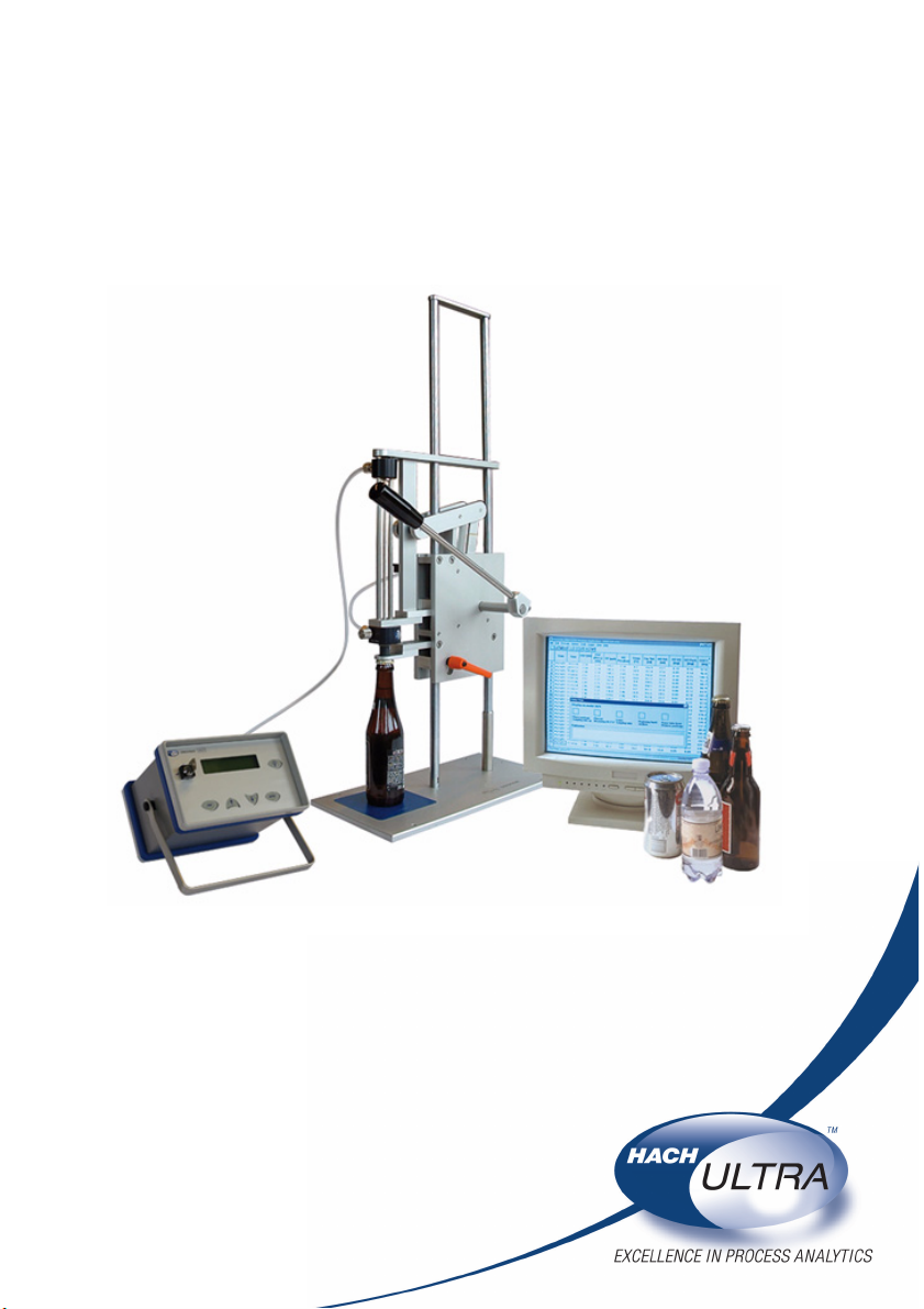
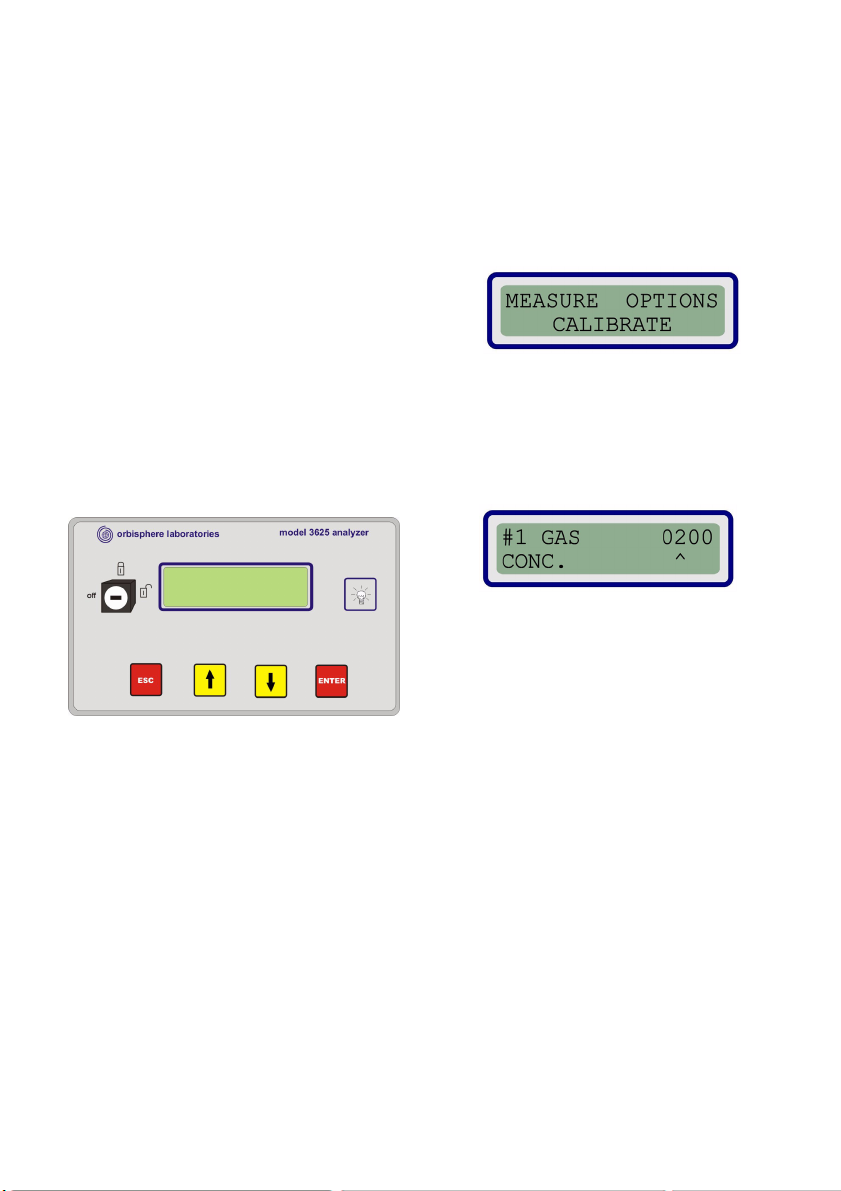
Instrument Controls
Delivered with the 29976 package piercer, is the
3625 indicating instrument. The front panel of the
instrument has several displays and controls.
The Key Switch should be turned to the
horizontal unlocked position to start the
instrument in measurement mode. The function
keys are only active if the key switch is in the
unlocked position. Use the vertical locked position
to avoid accidental modifications.
The Display has a two-line liquid crystal display
(LCD), having 16 characters per line.
A Light Button, when pressed, provides
illumination to the LCD for three minutes.
Four Function Keys provide simple operator
control over the instrument functions:
• ESC back one step.
• or move through the loop of
available data (selection blinks).
• ENTER confirm selection.
Main Menu
The main menu is reached by pressing ESC as
many times as needed:
• MEASURE: Measurement
• OPTIONS: Set up the instrument
• CALIBRATE: Calibration procedures
Entering Values
When entering numbers, several digits are
displayed. The caret symbol ^ represents the
cursor. After entering the last digit, the new value
is saved.
• increase or decrease the number
value
• ENTER move cursor one digit to right
• ESC move cursor one digit to left
• ENTER confirm last value entered
• move decimal point (when
applicable)
• ENTER confirm and exit
OrbiPack PC Software
The Beverage Package Analyzer system works
with the OrbiPack software. Ensure that:
• An RS232 cable is connected from your
PC to the instrument
• The PC is turned on
• The software is running
Page 2
Page 3
Measurement Menu
The flow chart below gives an overview of the MEASURE menu and sequence.
Page 3
Page 4

Measurement Process
Start the Instrument
The key switch on the instrument must remain in
the vertical position to perform measurements.
A configuration screen is displayed for a few
seconds, and then the message prompts you to
start the measurement sequence.
This message remains on for a few seconds, and
then the display shows the atmospheric pressure
(P1) and temperature (T1) in the analyzer
manifold. The pressure and temperature screen
alternates with the preceding message until you
either pierce a package (or press ESC to return to
the main menu).
Package Pressure Equalization
In order to perform an accurate analysis, partial
pressure in the package must be balanced
between the gas phase (headspace) and the
liquid phase (beverage). The packages to be
tested must be gently agitated in a longitudinal
direction for at least three minutes, using a
reciprocating shaker.
Prepare for Piercing
First, make sure the piercing knife used is correct
for the application (metal or plastic).
Check that the sampling tube is fully retracted
inside the piercing knife, and that the rubber seal
is in good condition and extends slightly below the
piercing knife tip.
To clamp a package into position, tilt the piercing
lever backward, install a package on the mat, and
bring the lever to the vertical position. The
package must be vertical on the base mat, and
centered in the upper positioning plate. During the
analysis, the package must remain firmly
clamped; if not check the positioning device
height adjustment.
Following instructions given by the system, pierce
the package where the surface is smooth and flat,
to get a good seal.
Pierce the Package
When prompted, pull the piercing lever down all
the way in a uninterrupted move.
During analysis, any pressure leak past the
rubber seal will alter results. Do not release the
piercing lever until it is all the way down.
Headspace analysis is automatically triggered.
When complete, the display will prompt you to
lower the sampling tube.
Holding the piercing lever:
• Lower the sampling tube until all the way.
The product sampling and analysis is
then automatically triggered.
• Adjust the flow meter to 150 ml/min.
Visually check that the liquid in the tubing and flow
chambers is not foaming. Increase the forcing gas
pressure if necessary.
When analysis sequences are over, the display
will ask you to remove package.
• Raise the sampling tube to its upper
position, holding it only by the handle bar
• Lift the piercing lever all the way (past the
2 step device, if applicable)
• Remove the empty package
The instrument should display the Pierce
package message, saying that the equipment is
now ready for a new package sampling.
Daily Cleaning (user maintenance)
Every 8 hours of use or when a measurement
session is over, whichever comes first, the
sampling circuit must be flushed to remove any
product deposit in the sampling lines and
chambers.
Perform a measurement routine, using a package
filled with clean water and some non aggressive
liquid detergent (do not use caustic soda). Use
either:
• 0.5% bleach (sodium hypo chlorite) at
room temperature
• 5% Contrad (dilute caustic detergent) at
40° C
The measuring instrument waits for the evidence
of piercing to continue, so press ENTER to
bypass this step. Repeat this operation with two
packages filled with water low in dissolved
oxygen.
Let the system purge run for 5 minutes to purge
liquid out and dry the system.
Page 4
Page 5

Note :
OrbiPack PC Software
ACCESS
The software is password driven, so be sure you
have a valid username and password. Depending
on your access level, some of the following
options may not be available to you.
PROCESS BAR
To hide or display the process bar, select it from
the View menu. The process bar is displayed at
the bottom left of the application window. It shows
five boxes indicating the sequences of the current
analysis. They correspond to the display
messages on the measuring instrument.
When one analysis step is completed, the
corresponding box turns green. However, if a
problem is found, the box turns red. Click the Help
button for further details.
SOTWARE OPTIONS
You may set several options before performing a
measurement. Select Options from the Tools
menu and click the desired tab.
General
Error Messages
You can enable or disable warning messages for
errors that may occur during package analysis. If
one or more box is checked, and the
corresponding error occurs, a pop up window
displays the error and asks if you want to save the
data anyway.
Inter Process Communication
The software allows for communication with other
control and management systems such as
SCADA and LIMS, etc. The communication
option is used to define the necessary
parameters.
If using this option, you must have the
appropriate communications software installed
on your PC.
This option allows you to set several parameters,
such as the gas being measured, and whether to
capture the data after each measurement.
Calibration Management
Each time a calibration is successfully completed,
the measuring instrument sends a message to the
OrbiPack software that is saved together with the
current date and operator's name.
A calibration deadline date can be set, by
checking the Expiry check box.
Page 5
Page 6

OrbiPack PC software (cont)
PACKAGE SET-UP
Supervisor level is required to access Package
set-up in the Package menu.
Package Characteristics
Enter the data corresponding to the package to be
tested. Up to 500 different package specifications
can be saved.
Alarms
Various thresholds can be entered to trigger
alarms. The values exceeding these limits will
appear in red in the data file.
Offsets
The offset is a multiplication factor applied to the
measured data (e.g. an offset factor set at 1.01
will increase the value by 1%).
DATA TABLE SETTING
The options selected here defines the data
elements listed in the data table (i.e. the file of
measurement data).
Measurement Columns
This requires supervisor level access and can be
made during or after the measurement sequence.
Several columns can be displayed for analysis
purposes, regarding data, units, or resolution
(decimal position).
Raw Data Columns
This is useful for diagnostic and troubleshooting
operations. This concerns data received from the
instrument before any computations are applied.
Formula
Five formula lines are available to compute
different equations of solubility. This allows you to
create and compute a specific new parameter, or
a different CO
corresponding to the new formulae are displayed
in the data table.
Page 6
solubility equation. The columns
2
Units
Select the units to be used and displayed in the
table columns.
Page 7

Setting Instrument Options
The instrument is equipped with customized
features for specific applications. Select
OPTIONS from the main menu, and then use the
keys until your choice is flashing. Press
ENTER to select it.
MEMBRANES
The selection of a membrane is a compromise
between the frequency of sensor services
(calibration, maintenance) and the sensor
sensitivity. It is also dependent on plant conditions
(frequency of analysis, O
level being measured,
2
etc.).
The default membrane for the O
sensor is model
2
2956A. It allows measurements within the ppb
range. If sensor measure drifts, or sensor service
frequency is high (less than once a month), then
membrane model 2952A is recommended.
SERIAL OUTPUT
The serial RS-232 interface provides
communication with an external computer or
printer.
Print - Provides a formatted list of results as text
to a PC or printer.
PC Com - Communication link between the Orbi-
Pack software and the measuring instrument.
The instrument sends the results data, and the
PC sends the package setup data.
Diagnostic - Provides a formatted data list.
There are two diagnostic data formats, depending on whether the instrument is in measure or
calibrate mode.
Upload - A test function that generates a text file
of the measuring instrument memory.
CONTINUOUS PURGE
This is a test function. When enabled, the system
continuously purges the thermal conductivity
sensor, and displays the sensor voltages for a
100% purge gas.
SAMPLING SYSTEM PURGE
This command opens the purge gas to the
beverage sampling system. This is used to flush
and dry the system during daily maintenance.
This can also be used to rapidly bring the O
sensor inside the working range.
NITROGEN TC SENSOR CORRECTIONS
Humidity Factor Correction
Moisture may affect the N
sensor readings. Use
2
this option to set the humidity correction factor of
the N
sensor.
2
Oxygen Factor Correction
in the measured gas may affect the N2 sensor
O
2
readings. Use this option to set the oxygen
correction factor of the N
sensor.
2
Temperature Correction
Significant changes in the sample temperature
influences the N
sensor reading. Use this option
2
to reduce this influence.
CHECK ROUTINE
This routine provides displays of the forcing gas
pressure, and allows you to check valve operation
on the system.
• Pressure - Forcing gas pressure check.
• ABC check - Automatic test routine for
manifold electro valves.
• D check - Automatic test routine for
pneumatic valves.
• Valve - This manual valve test function
allows you to individually open and close
each electro valve.
• Tub e - A test function for the positioning
switch on the sampling tube.
OXYGEN STABILITY
This option is used to monitor the O2 sensor.
When the O
on the PC screen will be displayed on a red
background.
stability criteria are not met, the data
2
2
Page 7
Page 8

Note :
Calibration
The flow chart below gives an overview of the calibration menu and sequences.
The following table shows the recommended sensor calibration interval for an average of 500 package
analyses per week. This proposed schedule should be modified accordingly for varying operating
conditions.
Sensor Calibration Interval
PT 1000 temperature sensor 1 year
Barometric (internal) pressure sensor (located inside instrument) 6 months
Package (external) pressure sensor (located inside manifold) 3 months
Electrochemical O
Electrochemical O
Thermal conductivity sensor 3 months
sensor with membrane 2952A
2
sensor with membrane 2956A (special)
2
4-6 weeks
2-4 weeks
The gas sensor should be calibrated after each membrane change. Wait a minimum of 30 minutes
before performing the calibration.
Page 8
Page 9

Calibration (cont)
PT-1000 TEMPERATURE SENSOR
This process requires the use of the 0°C simulator
(model 32116), supplied with your Beverage
Package Analyzer, and which plugs into the
PT1000 socket on the instrument’s back panel.
Prepare a package of water at room temperature,
and measure the temperature of water with a
certified thermometer and note this temperature.
Unplug the PT-1000 cable from the instrument
back panel, and select the PT-100, TWO POINT
calibration routine. Plug the simulator in the PT1000 socket, and when prompted for low point
temperature, enter 0°C. Select RESISTOR
calibration and when the low point voltage is
displayed, press ENTER.
Remove the simulator, and connect the PT 1000
cable. When prompted for high point temperature,
enter the previously noted water temperature.
Select LIQUID calibration, lower the sampling
tube into the water package, and press ENTER.
Wait until the voltage is stable, and press ENTER
to validate and calibrate.
BAROMETRIC PRESSURE SENSOR
Measure the barometric pressure using a certified
barometer in the location where the measuring
instrument is used. The reference barometric
pressure must be within ± 5 mbar.
If value is OK, press ESC. Otherwise enter the
barometric pressure in mbar and press ENTER.
PACKAGE PRESSURE SENSOR
For the external pressure sensor, connect a
certified pressure gauge to the forcing gas inlet
line. Adjust the forcing gas pressure to 4 bar
(gauge pressure).
It is recommended to use the TWO POINT
calibration procedure, which requires that you
work at two different pressures.
EC SENSOR (O
Two methods of calibrations are available:
• In air calibration: Expose sensor to
100% humid air (recommended)
• Direct calibration: Expose sensor to a
known source of O
flow chamber)
)
2
(requires an optional
2
To calibrate in air, remove the O
sensor (still
2
connected) from piercer, and wipe dry the sensor
protection grille. Put one drop of tap water in the
sensor storage cap. Install the cap sensor slightly
loose to avoid compressing the air inside.
Select O2 IN AIR from the calibration menu and
wait 5 minutes until the values displayed are
stable. Press ENTER to save the new calibration.
TC SENSOR (CO
2/N2
)
Four calibration methods are available:
• Partial pressure: Using a known
composition of CO
(or N2) at ~5 bar
2
(recommended)
• Fraction: Using a known composition
(preferably pure) of CO
(or N2) at
2
atmospheric pressure
• Calibration kit: Requires optional HUA
calibration kit. Using a known
concentration of dissolved CO
2
• Reference package: Using a package
with a known gas concentration content
as a reference
For the partial pressure method, use the
Orbisphere 32001.xxx calibration flow chamber.
The sensor is exposed to a known composition of
CO
(or N2) between 3 and 5 bar absolute
2
pressure (ideally close to the partial pressure
being measured), measured with an external
certified pressure gauge having a precision of ± 5
mbar.
Disconnect the external temperature sensor cable
and remove the sensor from the piercer. If the
sensor head is wet, rinse the tip with water, and
dry with a tissue. Make sure that the grille in the
front of the sensor is clean and dry.
Insert the sensor into the calibration flow chamber
and connect a source of calibration gas to the flow
chamber inlet. Close the flow chamber outlet
valve to build up the requested pressure in the
system.
Select PARTIAL PRESSURE from the calibration
menu and enter the absolute pressure of the
calibration gas. After 3 stable calibration cycles,
the calibration should be complete.
Page 9
Page 10

Measurement Troubleshooting
The following table lists possible measurement errors.
Symptom Probable Cause Corrective Action Sensor
No power.
Instrument does not start.
No display or backlight.
Downward drift during
measurement.
Low reading.
High reading.
High/low readings.
Unstable reading during
calibration.
Calibration impossible
Erratic readings.
Forcing gas pressure
P3 ≈ P4 during
measurement cycle.
Incorrect voltage.
Blown fuse.
Purge gas pressure too low.
Sample flow stopped. Correct and start a new test.
Leak in purge gas. Check line for leaks with soapy water.
Sample flow too low.
Incorrect calibration in gas (wet
membrane & protection grille ?)
Calibration values entered did
not match sample used.
Calibration gas flow restricted,
generating pressure pulse.
Improperly mounted protection
cap or membrane.
Leaking purge gas solenoid
valve in TC sensor.
Water condensation into the
thermal conductivity element.
Product in manifold electro
valves.
Check connections.
Check instrument voltage label on the
instrument rear panel.
Unplug the instrument and replace the
fuse.
Adjust pressure at regulator to get over
3 bubbles per second from sensor exit
tube (immerged in water).
Adjust sample flow according to
procedure.
Re calibrate the sensor according to
procedure.
Check that the entered numerical data
and units fit the gas concentration or
pressure.
Make sure calibration gas flows freely;
unscrew sensor collar ¼ turn to create a
leak, thus increasing gas flow during
calibration.
Sensor needs servicing.
Check purge gas sequence. If purge
gas solenoid leaks during measurement
phase (more than 1 bubble in 15
seconds), the sensor needs servicing.
In Options menu, turn on Continuous
Purge mode overnight to dry the sensor
cell.
Water condensation may seriously
damage the TC sensor cell.
Perform cleaning and testing of the
manifold valves.
CO
2
CO
2
CO
2
O
2
/CO
O
2
/CO
O
2
CO
2
O2/CO
CO
2
CO
2
2
2
2
Page 10
Page 11

Instrument Error Messages
The following table lists possible instrument error messages.
Message Reason Action
Prg
Purge gas failure Restore purge gas to specifications
Damaged sensing element
Perform the Continuous Purge test
Return sensor to Orbisphere
Chk Purge voltage drifting
Lmt Ramp limit violated
Too low
Too high
Check
Reception
Change the
Filter
Calibration out of
Bounds
Forcing gas pressure is insufficient to lift
the liquid to the sensors
Forcing gas pressure exceeds the limit set
in the OrbiPack 4.00 software for this
package type
The PC communication has failed
The gas filter in manifold may be clogged Replace the gas filter
Wrong membrane installed
Perforated or torn membrane
Two membranes instead of one
(or the opposite)
Check purge gas
Perform the Continuous Purge test
Reduce gas permeation
Perform the Continuous Purge test
Check forcing gas pressure
Verify that the forcing gas pressure is set at 500
mbar higher than the package pressure (P2)
Check forcing gas pressure, and check
OrbiPack 4.00 software max press. set limit.
Verify that the forcing gas pressure is set at 500
mbar higher than the package pressure (P2)
Check PC cable connection
Verify correct PC link and setup
Correct accordingly
Page 11
Page 12

 Loading...