

Page 1

DOC024.52.93051
ORBISPHERE Model 3100
Portable Analyzer
USER MANUAL
09/2019, Edition 10
Page 2

Page 3

Table of Contents
Section 1 General Information ......................................................................................................... 3
1.1 Disclaimer .................................................................................................................................... 3
1.2 Safety information ........................................................................................................................ 3
1.2.1 Use of hazard information ................................................................................................... 3
1.2.2 Safety recommendations ....................................................................................................4
1.2.3 Safety precautions .............................................................................................................. 4
1.2.4 Internal batteries .................................................................................................................5
1.2.5 Service and repairs ............................................................................................................. 5
1.2.6 Precautionary labels............................................................................................................ 6
Section 2 Specifications.................................................................................................................... 7
2.1 Technical specifications ............................................................................................................... 7
2.2 Instrument dimensions .................................................................................................................8
2.3 General principle of operation ...................................................................................................... 9
Section 3 Installation........................................................................................................................ 11
3.1 Overview .................................................................................................................................... 11
3.2 Unpacking..................................................................................................................................11
3.3 What you have received ............................................................................................................11
3.4 Installation startup checklist ....................................................................................................... 12
3.5 Reconnect battery power ........................................................................................................... 13
3.6 Instrument switches and connectors..........................................................................................14
3.7 Instrument connections ..............................................................................................................16
3.7.1 External power .................................................................................................................. 16
3.7.2 RS232 connection ............................................................................................................. 16
3.7.3 USB connection ................................................................................................................16
3.8 Connecting sample lines ............................................................................................................ 17
3.9 PC software installation ............................................................................................................. 18
3.9.1 Create new user table ....................................................................................................... 19
3.9.2 Create new measurement configuration table .................................................................. 20
3.9.3 Transfer files to the instrument..........................................................................................21
3.10 Instrument storage...................................................................................................................22
3.10.1 General guidelines .......................................................................................................... 22
3.10.2 Short term storage .......................................................................................................... 22
3.10.3 Overnight or weekend storage ........................................................................................ 22
3.10.4 Long term storage ........................................................................................................... 22
Section 4 User Interface .................................................................................................................. 23
4.1 Keypad and function keys ..........................................................................................................23
4.2 Data entry ..................................................................................................................................24
4.2.1 Select data ........................................................................................................................ 24
4.2.2 Enter data.......................................................................................................................... 24
4.3 User access ............................................................................................................................... 24
4.3.1 User lists ........................................................................................................................... 24
4.4 Measurement ............................................................................................................................. 25
4.4.1 Measurement mode ..........................................................................................................25
4.4.2 Measurement file...............................................................................................................25
4.4.3 Standard measurement display ........................................................................................ 26
4.4.4 Graphical measurement display........................................................................................ 26
4.4.5 Diagnostic measurement display ...................................................................................... 27
4.4.6 Measurement configuration list ......................................................................................... 28
4.4.7 Measurement alarms ........................................................................................................28
4.4.8 Out of range display .......................................................................................................... 29
4.5 Main menu ................................................................................................................................. 30
Section 5 Main Menu ........................................................................................................................ 31
5.1 Overview .................................................................................................................................... 31
5.2 Basic settings.............................................................................................................................32
1
Page 4

Table of Contents
5.3 Advanced settings ......................................................................................................................32
5.4 Calibration ..................................................................................................................................33
5.4.1 Barometric sensor calibration ............................................................................................33
5.4.2 Gas sensor calibration.......................................................................................................33
5.5 Default measurement configuration settings ..............................................................................34
5.5.1 Measurement configuration factory settings......................................................................35
5.6 Import / Export............................................................................................................................35
5.6.1 Exported files.....................................................................................................................36
5.7 Service instrument...................................................................................................................... 37
5.8 Service O2 channel ....................................................................................................................37
Section 6 Maintenance and Troubleshooting .............................................................................39
6.1 Maintenance ...............................................................................................................................39
6.1.1 Maintenance schedule ......................................................................................................39
6.1.2 Instrument batteries...........................................................................................................39
6.1.3 Oxygen sensor ..................................................................................................................39
6.2 Troubleshooting..........................................................................................................................41
6.2.1 List of events ..................................................................................................................... 41
6.2.2 Measurement troubleshooting ...........................................................................................42
6.2.3 O2 zero calibration troubleshooting...................................................................................42
6.2.4 High level calibration troubleshooting................................................................................42
Section 7 Parts and Accessories...................................................................................................43
7.1 3100 Kits .................................................................................................................................... 43
7.2 Spare parts and accessories ......................................................................................................44
2
Page 5

Section 1 General Information
1.1 Disclaimer
The information in this manual has been carefully checked and is believed to be accurate.
However, Hach assumes no responsibility for any inaccuracies that may be contained in this
manual. In no event will Hach be liable for direct, indirect, special, incidental, or consequential
damages resulting from any defect or omission in this manual, even if advised of the possibility
of such damages. In the interest of continued product development, Hach reserves the right to
make improvements in this manual and the products it describes at any time, without notice or
obligation.
1.2 Safety information
The manufacturer is not responsible for any damages due to misapplication or misuse of this
product including, without limitation, direct, incidental and consequential damages, and
disclaims such damages to the full extent permitted under applicable law. The user is solely
responsible to identify critical application risks and install appropriate mechanisms to protect
processes during a possible equipment malfunction.
1.2.1 Use of hazard information
WARNING
A warning is used to indicate a condition which, if not met, could cause serious personal injury
and/or death. Do not move beyond a warning until all conditions have been met.
CAUTION
A caution is used to indicate a condition which, if not met, could cause minor or
moderate personal injury and/or damage to the equipment. Do not move beyond a
caution until all conditions have been met.
Note: A note is used to indicate important information or instructions that should be considered
before operating the equipment.
3
Page 6
General Information
1.2.2 Safety recommendations
For safe operation, please read the entire manual before unpacking, setting up, or operating this
instrument. Pay particular attention to all warning and caution statements. Failure to do so could
result in serious injury to the operator or damage to the equipment.
To ensure the protection provided by this equipment is not impaired, do not use or install this
equipment in any manner other than that which is specified in this manual.
The instrument normally runs on battery power but can use an external power supply by
connecting it through the supplied adapter to an external power socket. To disconnect the
external power, unplug the adapter from the external power socket. Once disconnected the
instrument will revert back to battery power.
WARNING
When using an external power supply to power the instrument, ensure the external
power socket is earthed.
WARNING
In accordance with safety standards, it must be possible to disconnect the external
power supply of the instrument in its immediate vicinity.
1.2.3 Safety precautions
The 3100 Oxygen Analyzer is powered with a lithium battery pack. To ensure the safe use of
this instrument, read and pay close attention to the safety related information that follows.
When using the analyzer (also includes storage):
WARNING - Fire, Explosion, Burn Hazard.
• The temperature range over which the battery can be used, stored or discharged is -10
to 60°C. Use of the battery outside of this temperature range may result in:
• Damage to the analyzer's battery, resulting in a potential fire hazard from a battery
rupture and electrolyte leakage, and
• Reduced battery life expectancy
• Immediately discontinue use of the instrument if, while using or charging the battery,
the battery emits an unusual smell, smoke or the enclosure feels unusually hot to the
touch. Contact your Hach Service Center, if any of these problems are observed.
• In the event of a battery electrolyte leakage from the enclosure, avoid contact of the
electrolyte with the eyes. Do not rub the eye. Rinse well with water and immediately
seek medical care. If left untreated the battery fluid could cause damage to the eye.
• Never place the analyzer and its batteries in microwave ovens, high-pressure
containers, or on induction cookware.
WARNING - Fire, Explosion, Burn Hazard.
• Use of the analyzer should immediately be discontinued if the battery compartment is
exposed to moisture or flooding due to leakage, wear or misuse.
• Misuse of the analyzer may cause the internal battery to get hot, explode, or ignite and
cause serious injury.
• Do not expose the internal battery to any liquid such as water, beer or salt water, or
allow the battery to get wet.
• Do not disassemble or modify the analyzer or its battery. The internal battery pack
contains safety and protection devices which, if damaged, may cause the battery to
generate heat, explode or ignite.
• Do not place the battery/instrument on or near fires, stoves, or other high temperature
locations (above 60°C). Do not place the battery/instrument in direct sunlight, or use
or store the battery inside cars in hot weather. Doing so may cause the battery to
generate heat, explode, or ignite. Using the battery in this manner may also result in a
loss of performance and a shortened life expectancy.
4
Page 7

General Information
When charging the battery:
WARNING - Fire, Explosion, Burn Hazard.
Be sure to follow the rules listed below while charging the battery. Failure to do so may
cause the battery to become hot, explode, or ignite and cause serious injury.
• The temperature range over which the battery can be charged is 10 to 45°C. Charging
the battery at temperatures outside of this range may cause the battery to become hot
or to rupture. Charging the battery outside of this temperature range may also harm
the performance of the battery or reducethe battery's expectancy.
• When charging the batteries use the specified battery charger provided with the
instrument.
• When charging batteries, do not place the analyzer in or near fire, or into direct
sunlight. The additional heat can result in increased battery heating that can damage
the battery's built-in protection circuitry necessary for prevention of ignition of the
battery. Additionally, increased heat may cause activation of the batteries built-in
protection circuitry, thus preventing the battery from charging further.
• Do not continue charging the battery if it does not recharge within the specified
charging time. Doing so may cause the battery to become hot, explode, or ignite.
Contact your Hach Service Center, if any charging problems are observed.
Hach assumes no liability for problems that occur when the precautions listed above are not
followed.
1.2.4 Internal batteries
The instrument contains a rechargeable lithium battery pack as the main source of power, and
an RTC lithium metal battery on the mother board. Please read the following important safety
information regarding these batteries:
• Do not attempt to dismantle the rechargeable battery pack. If you feel it needs to be
replaced, please contact your local Hach representative for assistance.
• Used or end-of-life battery packs must be disposed of locally in a safe manner and
consistent with Local Authority regulations. If this cannot be done locally they can be
returned to Hach, but must be sent back in accordance with Packaging Instruction 965
issued by IATA.
• Faulty or defective battery packs may only be shipped (for repair or replacement) with them
inside the instrument. Disconnect the power supply (by reversing the process explained in
Reconnect battery power on page 13) before shipping.
• The mother board contains an RTC Lithium metal battery. It is forbidden to ship a used
mother board with the battery. If the mother board needs to be returned, then the battery
must be removed and disposed of locally in a safe manner and consistent with Local
Authority regulations. The mother board without the battery can then be shipped safely.
1.2.5 Service and repairs
None of the instrument’s components can be serviced by the user. Only personnel from Hach or
its approved representative(s) is (are) authorized to attempt repairs to the system and only
components formally approved by the manufacturer should be used. Any attempt at repairing
the instrument in contravention of these principles could cause damage to the instrument and
corporal injury to the person carrying out the repair. It renders the warranty null and void and
could compromise the correct working of the instrument and the electrical integrity or the CE
compliance of the instrument.
If you have any problems with installation, starting, or using the instrument please contact the
company that sold it to you. If this is not possible, or if the results of this approach are not
satisfactory, please contact the manufacturer’s Customer Service.
5
Page 8
General Information
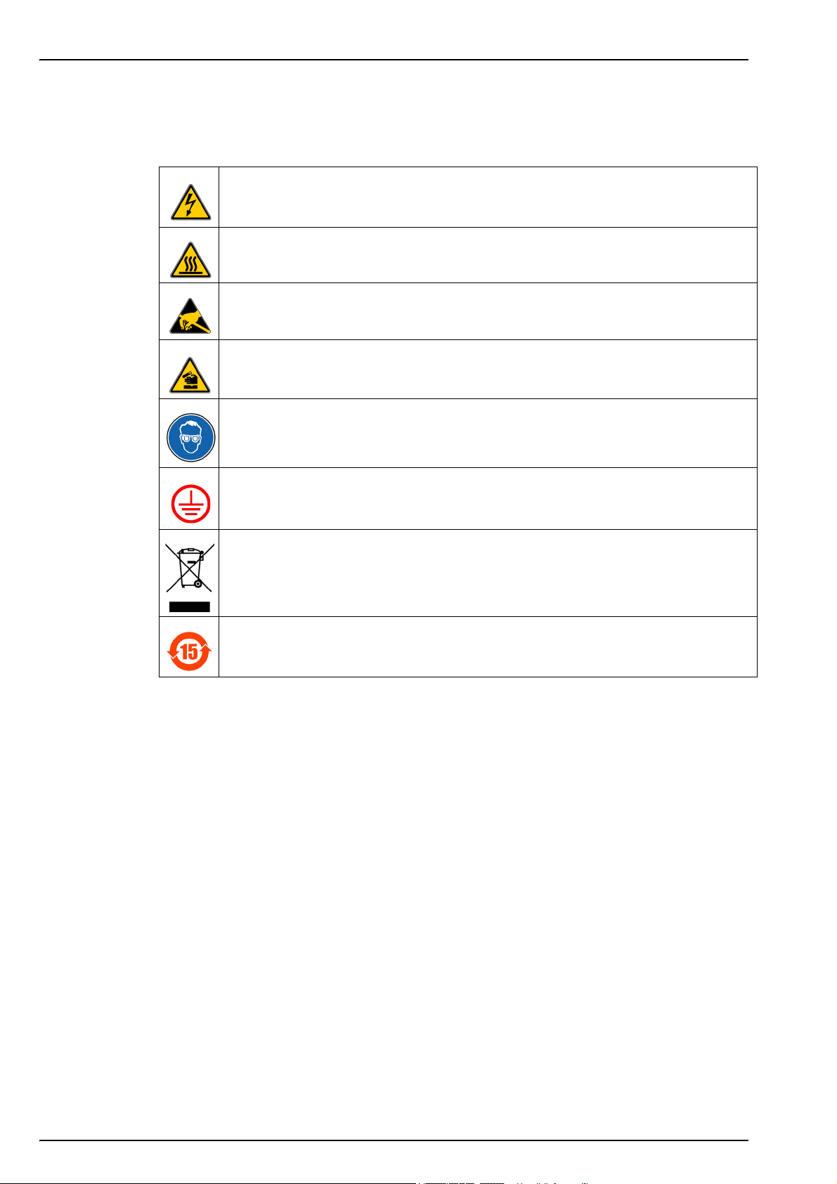
1.2.6 Precautionary labels
Read all labels and tags attached to the instrument. Personal injury or damage to the instrument
could occur if not observed.
This symbol, when noted on a product enclosure or barrier, indicates that a risk of electrical
shock and/or electrocution exists and indicates that only individuals
qualified to work with hazardous voltages should open the enclosure or remove the barrier.
This symbol, when noted on the product, indicates that the marked item can be hot and
should not be touched without care.
This symbol, when noted on the product, indicates the presence of devices sensitive to
electrostatic discharge and indicates that care must be taken to prevent damage to them.
This symbol, when noted on the product, identifies a risk of chemical harm and indicates that
only individuals qualified and trained to work with chemicals should handle chemicals or
perform maintenance on chemical delivery systems associated with the equipment.
This symbol, if noted on the product, indicates the need for protective eye wear.
This symbol, when noted on the product, identifies the location of the connection for protective
earth (ground).
Electrical equipment marked with this symbol may not be disposed of in European public
disposal systems. In conformity with European local and national regulations, European
electrical equipment users must now return old or end-of-life equipment to the manufacturer
for disposal at no charge to the user.
Products marked with this symbol indicates that the product contains toxic or hazardous
substances or elements. The number inside the symbol indicates the environmental protection
use period in years.
6
Page 9
Section 2 Specifications
2.1 Technical specifications
Specifications are subject to change without notice.
Non-flammable gaseous or liquid samples
Sample
Measurement range O
Accuracy O
Repeatability r
Detection limits O
Response time t
Measurements
Display units
Operating conditions
95
90
Sample temperature -5 to 45°C (23 to 113°F)
Sample pressure 0 to 10 bar (0 to 140 psi)
2
2
O
2
2
Usually less than 15 seconds but will vary depending on the sampling method
Holds up to 5,760 measurements
• 8 hours of data at a sampling frequency of 5 seconds
• 96 hours of data at a sampling frequency of 1 minute
O
concentration ppb, ppm, g/L, mg/L, mL/L, %O2, %air, %Vbar, ppmVbar
2
Pressure mbar, bar, Pa, hPa, kPa, MPa, psia, psig, atm, kgf/cm
Temperature °C, °F, K
Ambient temperature -5 to 45°C (23 to 113°F)
Relative humidity
0 to 2000 ppb
± 0.8 ppb or ± 2% of reading whichever is the greater
Note: Measurements above 400 ppb will require a high level adjustment
to guarantee accuracy
± 0.4 ppb or ± 1% of reading whichever is the greater
0.6 ppb
0 to 95% non-condensing for temperatures less than 30°C (86°F)
0 to 70% non-condensing for temperatures from 30 to 45°C (86 to 113°F)
ANALYSIS
2
ENCLOSURE
Weight 3.4 kg (7.5 lbs)
Dimensions (L x W x H) 200 x 170 x 190 mm (7.87 x 6.69 x 7.48 ins)
Maximum altitude 2000 m (6562 ft) maximum
Waterproof protection Stainless steel IP66 with polycarbonate sides
Internal rechargeable battery pack: Li-Ion 46Wh
Power supply
Battery life > 10 hours of continuous measurement
Battery charge time
European directives Low voltage Directive, EMC Directive
EMC standards EN 61326-1
Safety standard IEC/UL/CSA 61010-1
Overvoltage category Cat II
Digital display TFT color display 72 x 54mm (2.83 x 2.13 ins)
Digital connections
External power supply input: 100-240 VAC ±10% @ 47-63 Hz
External power supply output: 12 VDC, 3.75 A
Note: External power supply is not IP66
< 4 hours
Note: Charge time increases by 20% at a temperature above 35°C (95°F)
CERTIFICATIONS
INTERFACE
1 x USB (5 VDC) Input/Output mass storage device
Baud rate: 9600 (adjustable)
1 x RS232 (0-5 V)
serial output
Stop Bits: 1
Start Bits: 0
Parity: None
7
Page 10
Specifications
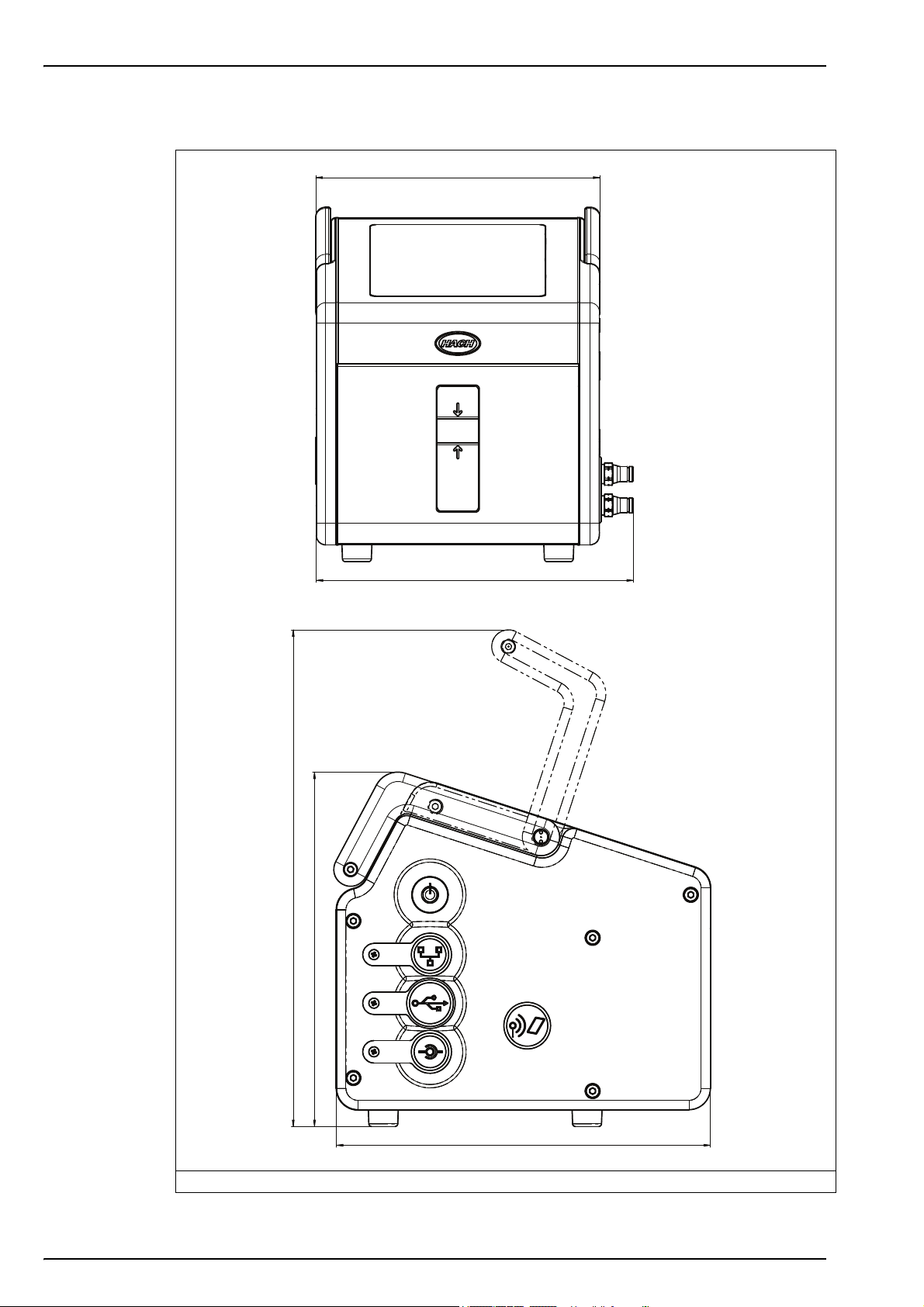
152
190
200
266
170 ~ 180
2.2 Instrument dimensions
Figure 1 3100 instrument dimensions (mm)
8
Page 11
2.3 General principle of operation
Optical sensing of oxygen originates from the work of Kautsky in 1939 where he demonstrated
that oxygen can dynamically quench the fluorescence of an indicator (decrease the quantum
yield). This principle has been reported in various fields of application such as monitoring
aquatic biology in waste water, tests for blood gas analysis and cell culture monitoring. The
method is now recognized by ASTM (American Society for Testing and Materials) for the
measurement of oxygen in water. Compared to classical oxygen detection using
electrochemical sensors, luminescent technology offers several advantages such as no oxygen
consumption, independence from sample flow velocity, no electrolyte and low maintenance.
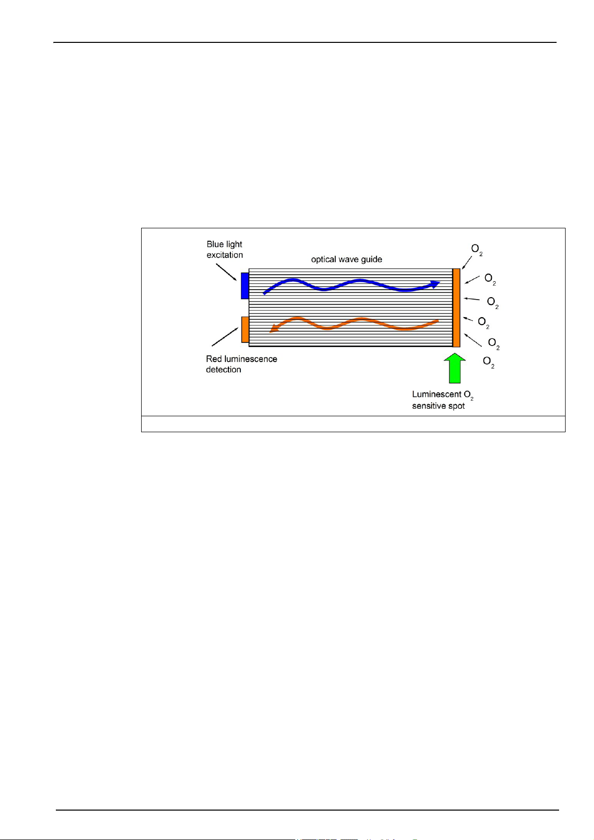
Optical sensing of oxygen is based on the measurement of the red fluorescence of a
dye/indicator illuminated with a blue light as shown below.
Specifications
Figure 2 Principle of optical oxygen detection using fluorescent dye
The dye fluorescence is quenched by the presence of oxygen. The oxygen concentration can
be calculated by measuring the decay time of the fluorescence intensity. The higher the oxygen
concentration is, the shorter the decay time will be. By modulating the excitation, the decay time
is transformed into a phase-shift of the modulated fluorescence signal, which is independent of
fluorescent intensity and thus of potential aging.
The oxygen partial pressure (pO
) is then linked to the corresponding phase-shift measurement
2
( to build the sensor calibration curve. This curve is described by the Stern-Volmer equation
where K
of the oxygen and thus the sensor sensitivity, f
is the indicator quenching constant (in mbar-1) representing the quenching efficiency
sv
is a constant and 0 is the phase-shift at zero
0
oxygen representing the unquenched fluorescence decay time of the dye.
The calibration curve thus relies on two parameters: the phase-shift at zero oxygen and the
luminescent spot sensitivity, K
. The dissolved oxygen concentration is then calculated with
sv
Henry’s law using the water solubility curve as a function of the temperature.
9
Page 12

Specifications
10
Page 13
Section 3 Installation
3.1 Overview
The ORBISPHERE 3100 instrument is a self-contained portable analyzer, configured to make
oxygen concentration measurements in gaseous or liquid samples. Up to 5,760 measurement
values can be stored in memory and downloaded to a personal computer for further analysis.
The analyzer is available in 3 different versions (for 4mm, 6mm and 1/4 inch connections).
This section provides all the necessary information to set up the instrument. If you have any
questions or experience any difficulties, do not hesitate to contact your Hach representative
regarding this procedure.
3.2 Unpacking
Carefully remove the instrument and its accessories from the box and packing material, referring
to the packing list included to confirm that everything has been delivered. Please visually
inspect the instrument for shipping damage. If anything is missing or damaged, contact the
manufacturer or your dealer immediately.
A thin protective film has been placed over the screen of the ORBISPHERE 3100 analyzer to
protect it from damage during transportation. For a clear view of the screen, this film must be
peeled off before using the analyzer for the first time.
CAUTION
A secondary more robust protective film has been factory installed over the screen to
protect it from damage and moisture ingress. Under no circumstances should this
protection be removed. If it becomes damaged in any way, please contact your local
Hach representative.
You may want to retain the box and other packing material in case you need to ship the
instrument at a later date. Please dispose safely and ecologically of the box and packing
material (if not being stored for future use).
It is recommended that you read through this manual before carrying out the installation.
3.3 What you have received
If you have ordered a DGK3100-XXXX kit, you will have received the following items:
Quantity Description
1 3100 instrument
1 External power supply adapter with plug
1 3 meters of plastic tubing
1 Tool kit (see Figure 3 on page 12)
1 Instrument carrying strap
1 Operator manual
11
Page 14
Installation
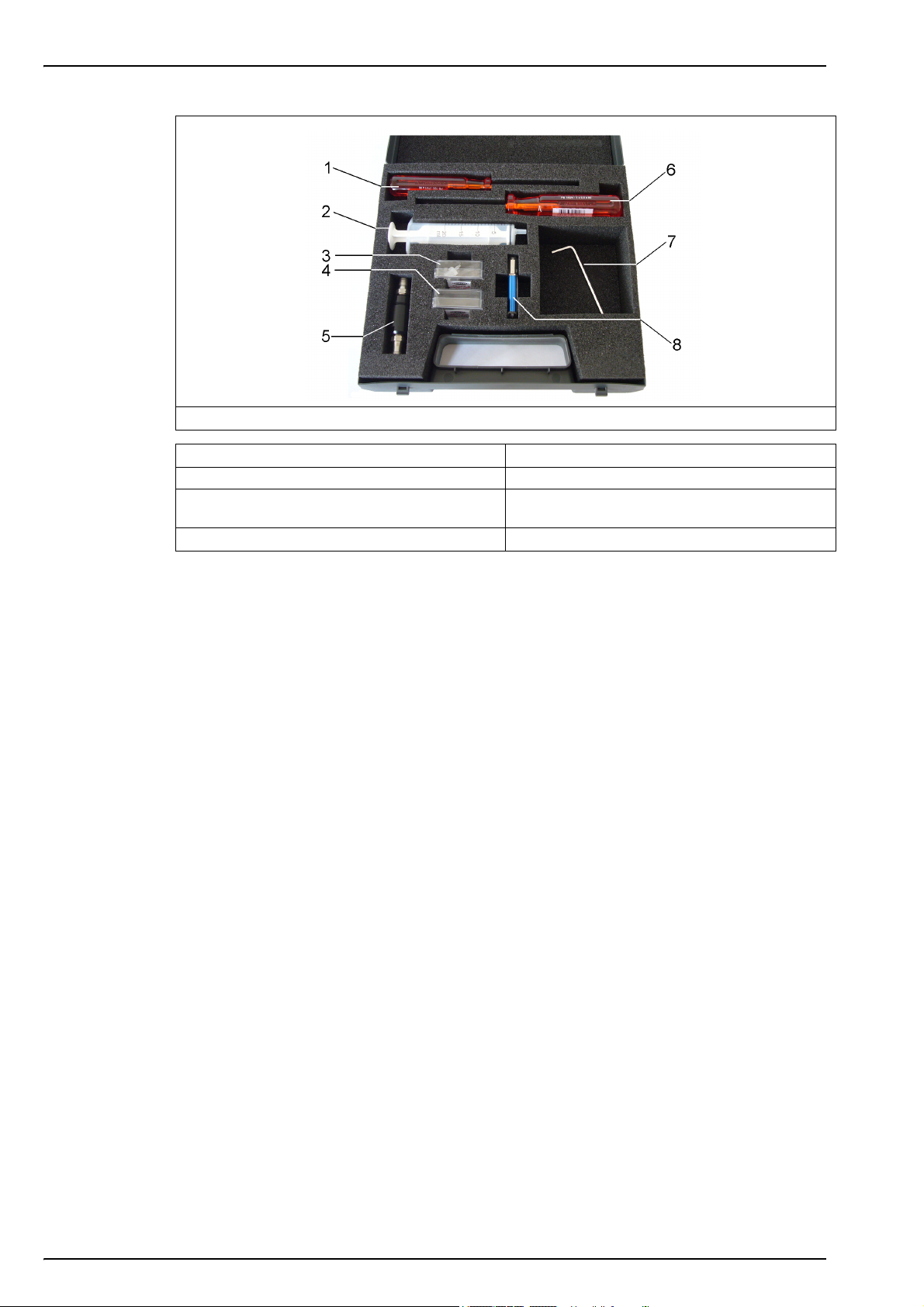
Figure 3 Tool kit (4mm instrument version illustrated)
1.
1 x Cross head screwdriver
2. 1 x Syringe 6. 1 x Flat head screwdriver
3. 1 x Box 5 syringe/instrument connectors (4mm
version only)
4. 1 x Box 10 meshes for particle filter
3.4 Installation startup checklist
1. Reconnect the battery pack in order to supply power to the instrument as described in
Reconnect battery power on page 13
2. Switch the machine ON using the ON/OFF switch (refer to Figure 4 on page 14) and check
that the batteries have sufficient power (refer to Figure 6 on page 26 for location of
remaining power indicator). If the batteries need charging, connect the instrument to an
external power source as described in External power on page 16.
Note: Once the battery pack has been reconnected and is fully charged, the instrument is ready to use.
However, to take advantage of its full functionality it is recommended to complete the following additional
steps before taking any measurements.
3. Next, familiarize yourself with using the instrument by reading the next section in this
manual entitled User Interface on page 23.
4. Set the date and time of the instrument's internal clock, as described in Basic settings on
page 32.
5. Install the 3100 PC software on your PC as described in PC software installation on
page 18.
5. 1 x Particle filter
7. 1 x Stainless steel or flexible tubing (stainless
steel illustrated)
8. 1 x USB key containing PC software
12
6. Set up the user configuration table using the PC software as described in Create new user
table on page 19.
7. Set up the measurement configuration table using the PC software as described in Create
new measurement configuration table on page 20.
8. Upload the user and measurement configuration tables to the instrument as described in
Transfer files to the instrument on page 21.
Page 15
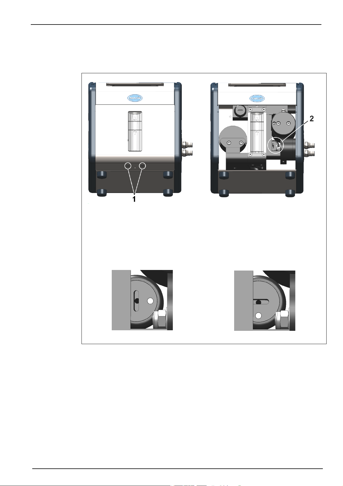
3.5 Reconnect battery power
For safety reasons, the battery pack will not be connected during shipment. Once the instrument
has been unpacked, the battery power should be reconnected using the following procedure:
Installation
1. Tilt the instrument towards the rear, to reveal two screws underneath (No. 1) that hold the
instrument front panel in place.
2. Using the cross screwdriver supplied in the tool kit, unscrew and remove these screws.
Lift off the front panel to reveal the internal battery power switch (No. 2).
3. Using the long-bladed flat-head screwdriver supplied in the tool kit, turn the switch a
quarter of a turn clockwise to reconnect the battery power. The diagrams below show the
switch in the OFF position as delivered (left) and in the ON position (right).
4. Replace the front panel and secure back in place with the two screws.
CAUTION
To avoid any damage to the instrument, it will be necessary to perform the above
procedure in reverse (i.e. turn the connection OFF) prior to any future transportation of
this instrument.
13
Page 16

Installation
3.6 Instrument switches and connectors
The following diagrams illustrate the side views of the instrument and their key features:
Figure 4 Left side view
1 Handle 4 USB connection
2 Instrument ON/OFF switch 5 External power supply connection
3 RS232 connection 6 Card identification system (option not yet available)
Figure 5 Right side view
1 Sample flow adjustment valve 2 Sample flow valve with inlet and outlet connections (the
sample inlet is at the top of the valve and the outlet at the
bottom). The valve has three positions: Sample line
PURGE; Sample flow ON; Sample flow OFF
14
Page 17

Installation
There is one switch and three connectors located on the left side of the instrument. The three
connectors are protected with a metal tab which must be unscrewed and removed before use.
Each tab has a symbol on it to indicate its function. Refer to Figure 4 on page 14 and the table
that follows:
This switch is used to turn the instrument ON or OFF. Push the button to turn
the instrument ON. A green indicator light on the lower left of the keyboard will
be illuminated when ON.
To turn the instrument OFF, push the button for a few seconds until the screen
display is dimmed. The instrument will then perform closing down procedures.
Once the green indicator light is extinguished, the instrument is OFF.
This is the RS-232 connection socket which uses an 8-pin LEMO plug to
connect the instrument directly to a PC.
This is the USB connection for mass storage devices, allowing uploading and
downloading of specific data files to and from the instrument.
This socket allows the instrument to be powered by an external power source.
A cable, with a 3-pin plug and adapter are supplied with the instrument.
This additional symbol is reserved for future use.
The sample inlet/outlet and sample flow adjustment valve are located on the right side of the
instrument. Refer to Figure 5 on page 14 and the table that follows:
Two symbols can be found relating to the sample flow adjustment
valve.
The symbol to the right indicates it is the flow adjustment valve, and
the symbol at the top indicates the direction for increasing and
decreasing the flow (turn clockwise to decrease the flow rate and
counter-clockwise to increase the flow rate).
Five symbols are located around the sample inlet and outlet
connections.
The first three symbols from left to right in the illustration indicate the
PURGE position, followed by the sample flow ON position, then the
sample flow OFF position. The illustration shows the sample flow in
the OFF position.
The other two symbols indicate that the top connection is for sample
input and the bottom connection for sample output.
The PURGE position is used to clear the sample line of any build up of air bubbles. For a
thorough purge, it is recommended to keep the valve in this position for 5 seconds. During this
operation, the sample flows directly from the inlet tubing to the outlet tubing. All measurements
are suspended during this time as the sample does not come into contact with the sensor.
The ON and OFF positions turn the sample flow on and off respectively.
15
Page 18

Installation
3.7 Instrument connections
3.7.1 External power
WARNING
When using an external power supply to power the instrument, ensure the external
power socket is earthed.
In addition to the internal rechargeable battery pack, the instrument can be powered by an
external power source using the supplied adapter and cable. Connect the adapter to the power
supply connection socket on the instrument (in Figure 4 on page 14), and plug into an external
power supply socket.
Note: When the instrument is connected to an external power source, the internal battery pack is
automatically recharged.
3.7.2 RS232 connection
This connection can be used to download measurement data and for real-time monitoring of the
measurements.
The data sent to the PC via this link is identical in format and content to that stored in the
measurement file on the instrument and which can be transferred using the USB mass storage
device (see Exported files on page 36 for details).
3.7.3 USB connection
The USB connection (in Figure 4 on page 14) is used for exporting and importing data from and
to the instrument. Tables can be set up on the PC using the 3100 PC software application and
then uploaded to the instrument using a USB mass storage device.
In addition, tables can be exported from the instrument to the USB storage device and then
imported to other 3100 instruments to standardize configurations.
For more details on this, refer to Import / Export on page 35.
16
Page 19

3.8 Connecting sample lines
Measurements can be taken on a continuous or sample by sample basis. In either mode, the
instrument must be connected to the sample line as follows:
1. The sample inlet and outlet connections on the instrument are located on the ON/OFF
sample flow valve (refer to Figure 5 on page 14 and enlarged in the diagram below):
1. Sample inlet
2. Sample outlet
Installation
2. Connect the inlet and outlet tubing to the sample source and to the drain, respectively. The
diagram above, shows the valve in the OFF position. To turn the sample flow fully ON, turn
the valve counter-clockwise until it clicks into position (about 1/8th of a turn). To remove any
residual air bubbles from the sample line, turn the valve to the PURGE position for 5
seconds before turning to the ON position.
Note: A length of stainless steel tubing is supplied in the tool kit (4mm instrument) and can be used instead
of plastic tubing on the outlet valve if the pressure in the instrument is high enough to cause excessive
movement of the plastic tubing.
3. If the sample contains particles, it is recommended to use a filter on the inlet tube to avoid
any clogging of the sample flow. The filter (including a box of 10 meshes) is contained in the
tool kit supplied with the instrument. It is also available separately as spare part number
DG33216 (4mm instrument), DG33317 (6mm instrument) or DG33318 (1/4 inch instrument)
and the set of 10 meshes as spare part number DG33217.
4. Control the sample flow using the adjustment valve located above the sample flow valve.
Refer to Figure 5 on page 14.
Flow rate guidelines:
• For cans and bottles the minimum recommended flow rate is 150mL/min. For small volume
packages a lower flow rate can be used but this should not be below 100mL/min.
• For tank and in-line applications the recommended flow rate should be above 200mL/min
and up to a maximum of having the flow adjustment valve fully open.
Note: The flow rates indicated with arrows on the flow meter (as illustrated below) are approximately
150mL/min (lower arrow) and 200mL/min (upper arrow). The silver bead gives an indication of the flow rate.
17
Page 20

Installation
3.9 PC software installation
The instrument is delivered with default user and measurement configuration tables. However,
to personalize the instrument by setting up your own tables you will need to use the PC software
which is included on the USB key supplied with the tool kit.
Install the PC software by inserting the USB key into your PC and running the setup program
(entitled setup.exe) from the directory Orbisphere 3100\Installation Files\PC Software on the
USB drive. Follow the on-screen instructions and the software will be installed on your hard disk
in a new directory: C:\Program Files\Hach Lange\3100 PC Software\.
On completion, a program icon will have been installed on your desktop for
easy access to the application.
Note: The PC software is compatible with the Windows 7, Vista, and XP operating systems.
Once the software has been installed, click on the desktop icon on the PC to launch the
application.
You will then be able to:
• Create or modify User Tables and Measurement Configuration Tables.
• Print any of the tables.
18
Page 21

3.9.1 Create new user table
From the application’s File menu, select New and then User Table.
A default user is created automatically, with an ID of “0”, a User Name of “Default”, and a level
of “User”. None of these fields can be changed. The password is set automatically to “1234”, but
this can be changed.
Use the Add option to add new users, and Delete to remove existing users. Copy and Paste
can also be used to add new users, and Cut can be used to delete existing users. Double click
on a field to edit the contents.
Installation
The table can be populated with a list of valid users. The following information is required:
• ID - 4 character numeric
• User Name - 16 character alphanumeric
• User Level - User or Supervisor
• Password - 4 character numeric for supervisor level only (not required for user level)
Note: Even if a password is set up at user level, when logging onto the instrument a password will not be
requested for user level access (only supervisor level access).
If any fields are invalid they are highlighted in red. In the example on the previous page, the
password is missing for user ID 1001. Greyed out fields indicate they cannot be updated.
Once the table is complete, select Close, Save or Save as from the File menu to save the file
to disk.
Note: The table can only be saved if there are no invalid fields (highlighted in red).
Once a table has been saved to disk, it can be edited using the Open option from the File
menu, to open an existing table.
The table can also be printed using the Print option in the File menu.
19
Page 22

Installation
3.9.2 Create new measurement configuration table
From the application’s File menu, select New and then O2 Instrument to create a new
measurement configuration table.
Note: The other two options, CO2 Instrument and Dual Channel Instrument are for future use.
A default entry is created automatically, with an ID of “0”, a Location Name and Product Name
of “Default”. None of these fields can be changed.
Use the same functionality as described for the user table, to add entries to the table. The
following information is required:
• Entry ID - 5 character numeric
• Location Name - 8 character alphanumeric
• Location Description - 32 character alphanumeric
• Product Name - 8 character alphanumeric
• Product Description - 32 character alphanumeric
• Measurement Mode - Continuous or Sample
• Sample Type - Select from a drop-down list of valid entries
• O2 Low Level Activation - Yes or No
• O2 Low Level Alarm - If activation set to yes, enter the low level value to trigger the alarm
• O2 High Level Activation - Yes or No
• O2 High Level Alarm - If activation set to yes, enter the high level value to trigger the alarm
• O2 Gas Unit Type - Select from a drop-down list of valid entries
• O2 Gas Unit - Select the display unit from a drop-down list of valid entries
• O2 Calibration Offset - Enter a calibration offset value if required
Once the table is complete, select Close, Save or Save as from the File menu to save the file
to disk.
Once a table has been saved to disk, it can be edited using the Open option from the File
menu, to open an existing table.
20
The table can also be printed using the Print option in the File menu.
Page 23

3.9.3 Transfer files to the instrument
When the two tables have been populated, they can be transferred to the instrument using a
USB storage device (typically a USB key).
1. From the PC copy the files to the USB storage device in a top-level directory of 3100. The
files will typically be located in:
C:\Program Files\Hach Lange\3100 PC Software\ with file extensions of .cdm (for
measurement configurations) and .ndu (for user tables).
Note: It is important that the file name extensions (.cdm and .ndu) are not changed as they will not be
recognized by the instrument software. Similarly, the files must be located in a top-level directory of 3100.
2. With the instrument switched ON, insert the USB storage device into the USB connection on
the left side of the instrument, and press the USB icon on the instrument front panel.
3. The first screen is for exporting files from the instrument to a USB storage device, so press
the right arrow to move to the next screen.
4. The next screen is the Import User Table screen. The user table will be recognized by the
instrument and the file name displayed in the highlighted box. If more than one user table is
on the USB storage device, press the Enter key to view a list of all the user tables, and use
the up/down arrows to scroll through the list. Press the Enter key to select.
Installation
When a table has been selected, press the down arrow key until the Import File text is
highlighted and press the Enter key to import the file. On completion, a message will appear
saying the instrument will have to be turned off and on again for the new table to take effect,
but as the measurement configuration table is still to be imported this message can be
ignored at this stage.
5. Press the right arrow to move to the Import Measurement Configurations screen. As with
the user table, select the measurement configuration table to import and press the down
arrow key until the Import File text is highlighted. Press the Enter key to import the file.
Again, on completion, a message will appear saying the instrument will have to be turned off
and on again for the new table to take effect.
6. As both tables have now been transferred to the instrument, turn the instrument OFF and
then back ON again for the new tables to take effect. When switched ON the two default
table entries will be loaded (i.e. default user and default measurement configuration). These
can be changed by following the instructions in User lists on page 24 and Measurement
configuration list on page 28.
21
Page 24

Installation
3.10 Instrument storage
3.10.1 General guidelines
When not in use, ensure the instrument is turned OFF by pressing the ON/OFF switch until the
green indicator light is extinguished. Refer to Figure 4 on page 14.
CAUTION
If the instrument is to be stored in an environment where the temperature is likely to be
0°C (32°F) or below, then to avoid any damage to the instrument make sure there is no
liquid inside. Do this by first running warm water through the instrument and dry by
flowing dry air or N
Refer to Figure 5 on page 14
3.10.2 Short term storage
For short term storage (between measurements or up to a maximum of 6 hours), leave the
sample in the instrument by turning the sample flow valve to the OFF position. Refer to Figure 5
on page 14.
3.10.3 Overnight or weekend storage
through it. Then turn the sample flow valve to the OFF position.
2
When storing the instrument overnight or over a weekend, run clean water through the
instrument to prevent passageways from becoming clogged and then turn the sample flow valve
to the OFF position. Refer to Figure 5 on page 14. Wipe down the outside of the instrument with
a clean damp cloth.
3.10.4 Long term storage
For long term storage (more than 1 week), run warm water through the instrument followed by
20 mL of ethanol (EtOH). Dry by flowing dry air or N
sample flow valve to the OFF position. Refer to Figure 5 on page 14. Wipe down the outside of
the instrument with a clean damp cloth. It is recommended to fully charge the battery prior to
any long term storage.
Note: If the instrument has been in storage for more than 4 weeks, remember to fully recharge the battery
pack before use.
through the instrument, and then turn the
2
22
Page 25

Section 4 User Interface
4.1 Keypad and function keys
1. Cancel key 4. Arrow keys
2. USB key 5. Enter key
3. Sample or continuous mode key 6. RFID key
The user interface of the instrument consists of a display screen, 6 function keys and a set of 4
arrow keys in the center. A green light at the bottom left of the keypad indicates if the instrument
is ON. No light indicates the instrument is OFF. The keypad is touch sensitive and will respond
to each key being pressed. As the key is touched a blue light will be appear underneath to
indicate selection of that key. If a key is selected that is not available or has no meaning during
the current operation, then the key will be displayed above the measurement value with a line
drawn through it.
7. Measurement key
Note: The keypad can be locked and unlocked pressing the keys RFID, USB and RFID in sequence.
The keys have the following functions:
• Cancel data input.
• Exit from a menu and display the measurement screen.
Note: This key will be referred to as the Cancel key in this manual.
• Display the main menu.
• Select an option.
• Validate the input and go on to the next step.
Note: This key will be referred to as the Enter key in this manual.
• Import data from a USB mass storage device.
• Export data to a USB mass storage device.
• Card identification system (not yet available).
• When pressed twice in quick succession a screenshot will be taken
(maximum of 10) that can be transferred to a USB key using the Import /
Export option from the Main Menu (see Import / Export on page 35).
• Define if measurements are in sample or continuous mode. Continuous
mode displays the bottle symbol with a cross through it in the top right of
the measurement screen. Sample mode displays the bottle symbol without
the cross.
• When in sample mode use this icon to Start/Stop measurements. When
started the bottle symbol is shown in green. When stopped the symbol is
greyed out and a “Measurement stopped” message displayed.
• Up arrow - Scroll up through a list or menu.
• Down arrow - Scroll down through a list or menu.
• Left arrow - Go back to the previous screen (or data element) in sequence.
• Right arrow - Go to the next screen (or data element) in a sequence.
23
Page 26
User Interface
4.2 Data entry
4.2.1 Select data
To select a data item from a list, use the up and down arrow keys to highlight the required value,
followed by the Enter key to select it.
4.2.2 Enter data
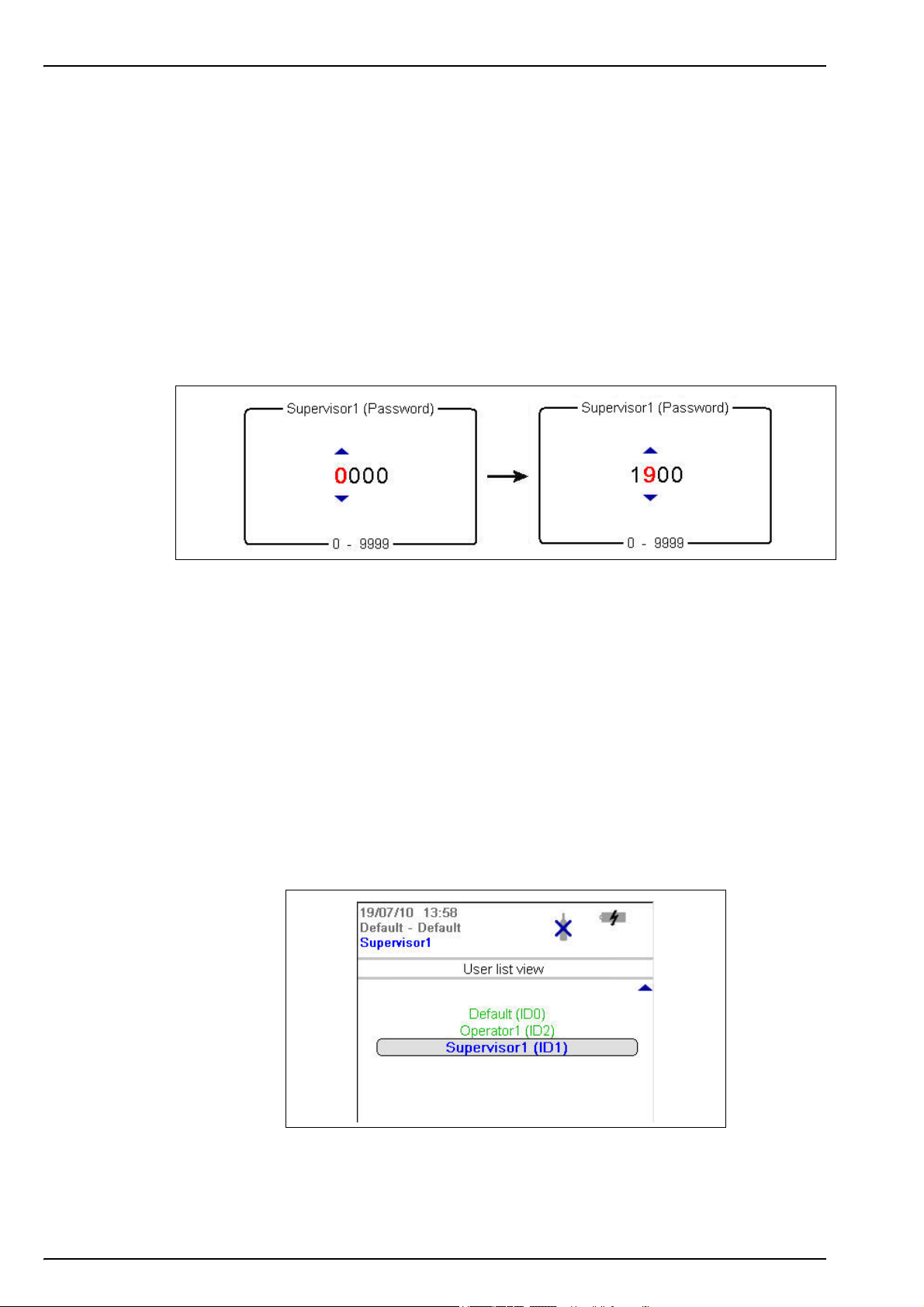
When required to enter data (e.g. a password in the following example), a screen will be
displayed showing the field default value (0000) and the valid range (0 - 9999) below it.
The first character will be highlighted in red with arrows above and below. Press the up and
down arrow keys to increase or decrease the value. When the correct value is showing, press
the right arrow key to move to the next character and enter that value until all characters have
been entered.
On completion, press the Enter key to validate the field. If the field is invalid an appropriate
message will be displayed.
The Cancel key can be pressed at any time during data entry to abort the process.
4.3 User access
Two access levels are available:
• User - basic measurement functions
• Supervisor - password protected with access to additional views and the Main Menu
4.3.1 User lists
From the measurement screen, press the right arrow key until the list of users stored in the
instrument is displayed. Standard users will be displayed in green and supervisors in blue.
Note: These user lists are defined by the user on the PC (see Create new user table on page 19) and
imported into the instrument (see Transfer files to the instrument on page 21).
24
Press the up and down arrow keys to scroll through the list of users. When the required one is
highlighted press the Enter key to select it. If a supervisor level user is selected a password will
be required (by default Supervisor1 is 5678). On completion, the display returns to the
measurement screen.
Page 27

4.4 Measurement
4.4.1 Measurement mode
Two measurement modes are available:
• Continuous mode
• Sample mode
Continuous mode is typically used for process measurement, whereas sample mode is aimed at
laboratory measurements of small volume individual samples such as cans, bottles, etc.
Continuous mode cycle
• Measurements are taken and refreshed on the display every 5 seconds
• The measurement data is stored in the measurement file at the user defined storage interval
(defined in Advanced settings on page 32)
Sample mode cycle
• Measurements are taken and refreshed on the display every 5 seconds once the Start/Stop
measurements button is pressed
User Interface
• Measurements are stopped if:
• The timeout is exceeded (2 minutes)
• The Start/Stop measurements button is pressed
• The measurement is stable
• When the measurement process is stopped, the screen displays the final measurement
value alternating with a Measurement stopped message. The final measurement value is
then stored in the measurement file
4.4.2 Measurement file
The measurement file is configured from the Main Menu (see Advanced settings on page 32).
Supervisor access is required for this.
Two storage modes are available:
• Rolling buffer - When the file is full, the latest measurement set replaces the oldest one
continuously (first-in, first-out)
• Store once - When the file is full (5,760 positions), the recording of measurement stops
25
Page 28

User Interface
4.4.3 Standard measurement display
1. Instrument date and time 7. Battery life remaining
2. Measurement location and product name 8. USB symbol indicates USB key attached
3. User name 9. Measurement mode (continuous shown)
4. Sample temperature 10. High level alarm value (if set)
5. Measured gas 11. Low level alarm value (if set)
6. Measurement unit 12. Measurement value
Figure 6 Measurement display
Note also:
• The user name will be displayed in green for a standard user, or blue for a supervisor
• The battery life remaining will not be displayed if using mains power supply, instead the icon
will show the battery recharging symbol:
• The measurement value is normally displayed in blue, but will be displayed in red if it is
outside the high or low value alarm limits
• If measurement is in sample mode, the bottle icon is displayed at the top right of the screen.
If measurement mode is set to continuous, the bottle icon will be displayed with a cross
through it
• The measurement display is refreshed every 5 seconds
4.4.4 Graphical measurement display
To access this display from the standard measurement display screen, press the right arrow key
on the keypad until the graphic screen is displayed:
26
This screen gives a graphical representation of the measurement with the numeric value of the
measurement displayed at the end of the curve. The above example shows the measurement in
sample mode.
Page 29
User Interface
The numeric measurement value at the end of the curve is refreshed every 5 seconds. The
curve is refreshed every 5 seconds in sample mode. In continuous mode, the refreshment rate
is the same as that defined as the storage interval parameter (see Advanced settings on
page 32).
The graphic timescale is displayed at the bottom of the screen. This value can be increased or
decreased (4 zoom levels) by pressing the up and down arrows on the keyboard. These values
are also dependant on the storage interval parameter; the greater the storage interval, the
greater the available timescales.
The measurement scale is calculated automatically with the maximum and minimum values
displayed at the top and bottom of the y axis respectively.
In sample mode, a symbol is displayed to denote the end of the
measurement (illustrated right). This is displayed in green if the stop
criteria are met, or red to denote an erroneous measurement.
The color of the curve has the following meaning:
• Grey (normal): The channel is out or the measurement is out of range
• Green (bold): The channel is being calibrated
• Grey (bold): The measurement has not started (sample mode only)
• Red (bold): An alarm has been activated
• Blue (bold): Normal measurement
The graphical display is cleared and restarted after the following events:
• At instrument startup
• After a change to the storage mode (see Advanced settings on page 32)
• After a change to the measurement mode (sample or continuous)
• After a change to the current measurement configuration
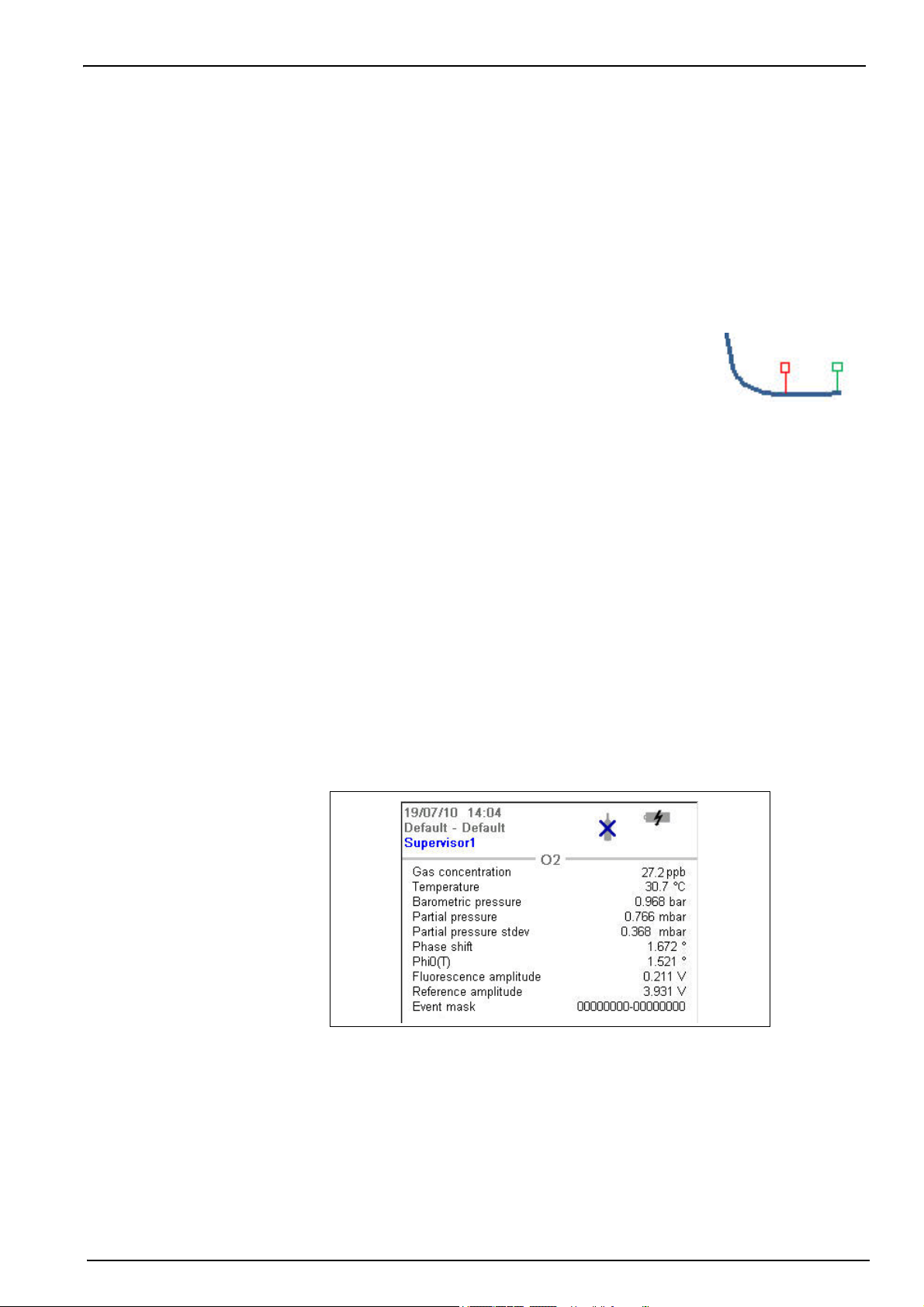
4.4.5 Diagnostic measurement display
The diagnostic measurement display is only accessible if the user is logged on at supervisor
level. To access this display from the standard measurement display screen, press the right
arrow key on the keypad until the following screen is displayed:
The information displayed can be useful for troubleshooting purposes.
Note: There are two event masks at the bottom right of the screen. The first is the common event mask and
the second is the oxygen channel event mask. For details of their meanings refer to the tables in List of
events on page 41.
27
Page 30
User Interface
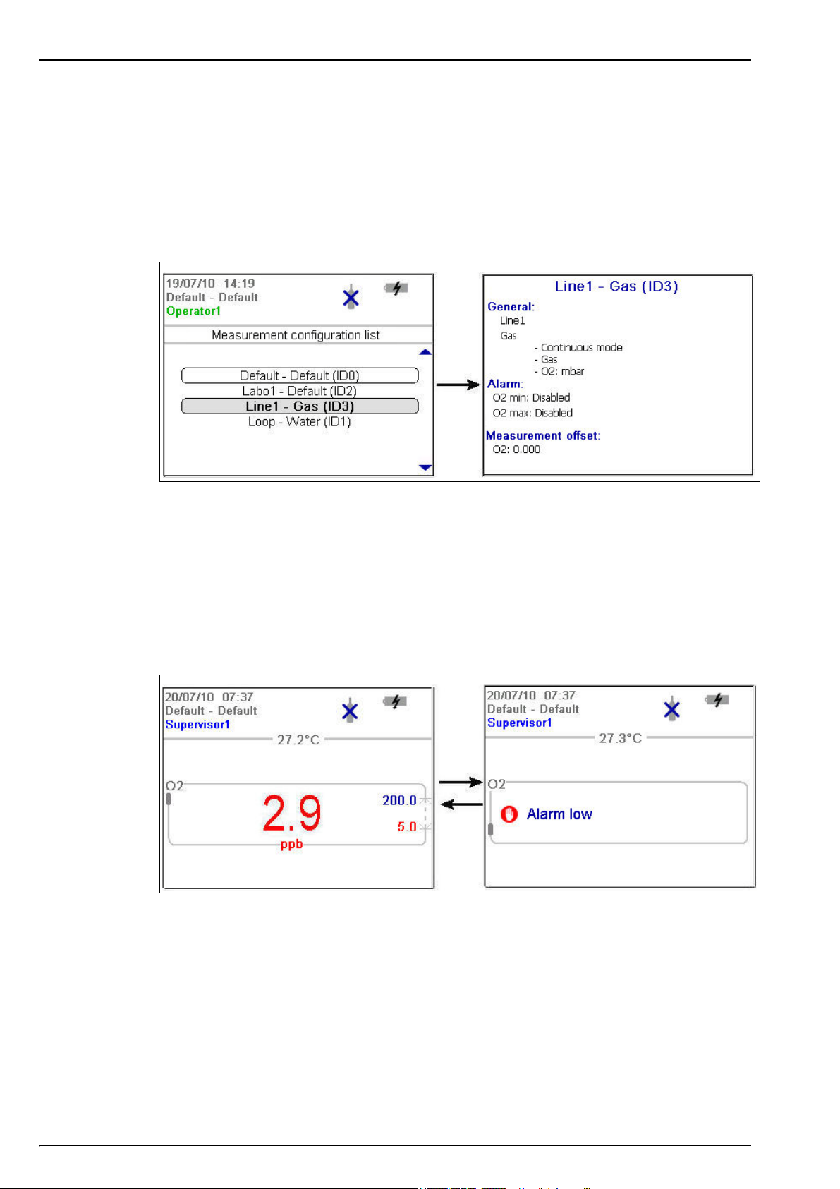
4.4.6 Measurement configuration list
From the measurement screen, press the right arrow key until the list of measurement
configurations stored in the instrument (below left) is displayed.
Note: These configurations are defined by the user on the PC (see Create new measurement configuration
table on page 20) and imported into the instrument (see Transfer files to the instrument on page 21). Only
the default configuration (ID0) can be edited by the user from the instrument. To do this the user must be
logged on at supervisor level and the default parameters can then be edited from the Main Menu as
described in Default measurement configuration settings on page 34.
Press the up and down arrow keys to scroll through the list of measurement configurations.
When the required one is highlighted press the Enter key to select it. The selected configuration
details will be displayed on screen (above right).
Press the Enter key again to select this configuration and return to the measurement screen, or
Cancel to reject it and return to the measurement configuration list screen.
4.4.7 Measurement alarms
If a problem occurs during measurement, the system will alternate every second between the
measurement screen (shown left below) and the error message screen (shown right below).
28
In the example illustrated above, the measurement value is displayed in red to indicate a
measurement outside the pre-defined alarm limits. The alarm low value on the right side of that
screen is also displayed in red to indicate the reason the measurement value is in error.
The error message screen gives the reason why the measurement is invalid (i.e. Alarm low in
the example above).
Note: If the measured value goes back above this low value, the value is again displayed in blue and the
error message screen is no longer shown.
Page 31

4.4.8 Out of range display
The sensor measures dissolved oxygen up to a maximum value of 2 ppm. Should the measured
concentration go above this value, then the screens illustrated below will be displayed.
The measurement value will be displayed as hyphens and will alternate with an “Out of range”
message.
User Interface
If the measurement is still out of range after 5 minutes of continuous measurements, the
measurement cycle will increase from 5 to 60 seconds.
Once the value falls below the out of range limit, then the measurement cycle returns to a 5
second interval and the measured value is displayed.
29
Page 32

User Interface
4.5 Main menu
The main menu is only accessible if the user is logged on at supervisor level and is accessed
using the Enter key from the standard or diagnostic measurement display.
The main menu options are described in detail in Main Menu on page 31 of this manual. There
are 7 main options:
1. Basic settings
2. Advanced settings
3. Calibration
4. Default measurement configuration settings
5. Import / Export
6. Service instrument
7. Service O2 channel
• Language selection
• Date and time adjustment
• Backlight management
• Units management
• File measurement management
• Communication
• Miscellaneous
• Barometer calibration
• O2 zero calibration
• O2 high level adjustment
• Instrument settings
• O2 channel settings
• O2 advanced settings
• Export files
• Import user table
• Import measurement configuration table
• Import solubility parameters
• Import instrument basic settings
• Board information
• Temperature checking
• Sample temperature calibration
• Miscellaneous
• O2: Calibration parameters
• O2: DC measurement parameters
• O2: AC diagnostic parameters
• O2: Calibration timer
30
Page 33
Section 5 Main Menu
5.1 Overview
The main menu is only available to users logged on at supervisor level.
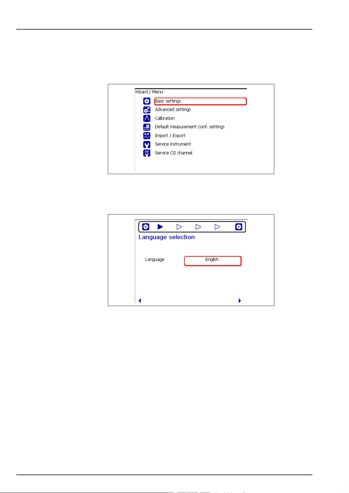
To access the main menu from the measurement screen, press the Enter key on the main
keypad to display the following options:
Scroll through the menu using the up and down arrow keys. When the required option is
highlighted, press the Enter key to select it and display the sub option screens. If, as in the
example above, the Basic Settings option is selected, the first of the sub-option screens is
displayed as illustrated below:
This screen allows you to select the working language of the instrument.
Choose the field to update from those available using the up and down arrows and then press
the Enter key to select it.
The arrows at the bottom of the screen indicate that you can use the left and right arrows to
scroll through the sub-options available from the Basic Settings menu option.
The chevrons at the top of the screen indicate how many sub-options are available. The one
currently selected is highlighted in blue. In the above example, this indicates that this is screen 1
in a series of 4 available.
31
Page 34

Main Menu
5.2 Basic settings
Language Select the working language for the instrument from the list available
Date format Define the display format for the date (DD/MM/YY or MM/DD/YY)
Date Enter the day, the month and the year in the format defined above
Time format Enter the display format for the time using a 12 or 24 hour clock
Time Enter the hour and minutes in the format defined above
Backlight level Enter the scale of brightness (max, comfortable, standard, economy or min)
Pressure unit Choose the barometric pressure unit from the list available
Temperature unit Choose the temperature unit from the list available
5.3 Advanced settings
Language Selection
Date and Time Adjustment
Backlight Management
Units Management
File Measurement Management
Choose from a rolling buffer or store once:
• Rolling buffer: When the file is full, the latest measurement set replaces
Storage mode
Storage interval
Clear data Select this option to erase the measurement storage file
RS232 Check the box if the RS232 link is required
Baud rate Select the baud rate from the list available
This option allows the default measurement configuration parameters to be restored
the oldest one continuously (first-in, first-out)
• Store once: When the file is full (5,760 positions), the recording of
measurement stops
Define the interval for storing measurements from the list available.
The interval is in seconds with the number of hours of measurements
available shown in brackets e.g. 10s (16h) indicates measurements are
stored every 10 seconds, which will give 16 hours of continuous storage.
Note: This parameter also defines the refreshment rate for the graphic
measurement display.
Communication
Miscellaneous
32
Page 35

5.4 Calibration
5.4.1 Barometric sensor calibration
The upper box shows the current barometric pressure as measured by the instrument. Using a precision
certified barometer, measure the barometric pressure in the location where the instrument is used. If the
values differ, enter the correct value in the box provided and select Validate calibration
5.4.2 Gas sensor calibration
There are two calibration modes available
• Zero calibration
• High level adjustment
The zero calibration method is the best method to guarantee the sensor specifications.
To get more accurate measurements for samples with higher oxygen concentrations (above 1%
oxygen which corresponds to about 400 ppb dissolved O
performed using a gas mixture containing 2% oxygen. However, this should not be done without
first ensuring the zero point is accurate (i.e. by performing a zero calibration first).
Barometer Calibration
2
Main Menu
) a high level adjustment can be
Zero calibration
O2 zero calibration
1. Rinse flow path with 20 mL of ethanol (EtOH) using the syringe and connectors supplied in the tool
kit
2. Connect a cylinder of oxygen free gas (minimum 99.999% purity) to the instrument and adjust the
flow to approximately 100 mL/min
3. Let the oxygen free gas run through the instrument for 5 minutes
4. Press the Enter key to start the calibration
5. Wait until the Signal in range and Stability reached fields display Yes which indicates the
calibration is within acceptable limits. The Calibration possible field should also display Yes at this
point. Press the Enter key to complete the calibration
6. Accept (OK) or reject (Cancel) the new calibration data
High level adjustment
There are three possible modes for high level adjustments:
• Using a reference gas mixture (gas cylinder)
• Using a known oxygen sample (reference sample)
• Enter a factory parameter provided by Hach (this option is only required when the sensor
spot has been replaced)
If the calibration mode displayed is not the required mode, then press the Enter key and select
the required mode from the three options available in the drop-down list:
• Factory parameter
• Reference sample
• Ref. gas bottle
O2 high level adjustment - Factory parameter
1. In the Calibration mode window select Factory parameter
2. Scroll down to the Reference value window and enter the factory parameter as found on the
package of the LDO spot (model number DG33218)
3. Scroll down to the Start Calibration window and press the Enter key to start the calibration
4. Accept (OK) or reject (Cancel) the new calibration data
33
Page 36

Main Menu
O2 high level adjustment - Reference sample
1. Run the reference sample through the instrument and adjust the flow to approximately 150 mL/min.
2. In the Calibration mode window select Reference sample
3. Scroll down to the Reference value window and enter the oxygen value of the sample
4. Let the sample run through the instrument for 5 minutes to stabilize the measurement
5. Scroll down to the Start Calibration window and press the Enter key to start the calibration
6. Wait until the Signal in range and Stability reached fields display Yes which indicates the
calibration is within acceptable limits. The Calibration possible field should also display Yes at this
point. Press the Enter key to complete the calibration
7. Accept (OK) or reject (Cancel) the new calibration data
O2 high level adjustment - Ref. gas bottle
1. Rinse flow path with 20 mL of ethanol (EtOH) using the syringe and connectors supplied in the tool
kit
2. In the Calibration mode window select Ref. gas bottle
3. Scroll down to the Reference value window and enter the oxygen value of the reference gas in
%Vbar
4. Connect the gas sample to the instrument and adjust the flow to approximately 100 mL/min.
5. Let the gas mixture run through the instrument for 5 minutes to stabilize the measurement
6. Scroll down to the Start Calibration window and press the Enter key to start the calibration
7. Wait until the Signal in range and Stability reached fields display Yes which indicates the
calibration is within acceptable limits. The Calibration possible field should also display Yes at this
point. Press the Enter key to complete the calibration
8. Accept (OK) or reject (Cancel) the new calibration data
5.5 Default measurement configuration settings
Instrument Settings
Select between continuous or sample mode.
Instrument mode
Sample type Select the sample type from the list available
O2 gas unit type Select the gas unit type from the list available
O2 gas unit Select the display unit from the list available
O2 high alarm
O2 low alarm
O2 measurement offset
Continuous mode is typically used for process measurement, whereas
sample mode is aimed at lab measurements of small volume individual
samples such as cans, bottles, etc.
O2 Channel Settings
Check the box to set the measurement high alarm.
If set, enter the high level value to trigger the alarm. When measurements
exceed this value an alarm will be triggered
Check the box to set the measurement low alarm.
If set, enter the low level value to trigger the alarm. When measurements fall
below this value an alarm will be triggered
O2 Advanced Settings
If required, enter a value (positive or negative) for the measurement offset.
This value will be used to adjust the measurement accordingly
34
Page 37

5.5.1 Measurement configuration factory settings
The following table shows the factory defined oxygen measurement configuration settings for
the instrument:
Instrument Settings
Instrument mode Continuous mode.
Sample type Beer
Gas unit type Dissolved
Gas unit ppb
High alarm Disabled
Low alarm Disabled
O2 measurement offset 0.0 ppb
5.6 Import / Export
Export Files
This option allows you to export a number of different files (see Exported files on page 36 for details) to a
USB mass storage device. Once written to the USB device, it can then be used to load these files to
other 3100 instruments or to a PC.
Make sure a USB device is connected and then press the Enter key to start the process. A progress bar
is displayed at the bottom of the screen.
Wait until the export complete message is displayed on screen before removing the USB device.
Import User Table
This option allows you to import user tables from a USB mass storage device. These tables could be
exported from other 3100 instruments or from the 3100 software application installed on your PC. The
tables are recognized by having an extension of .ndu. If more than one table is found on the device, you
will need to select the table you want from the list.
Press the down arrow key to highlight the Import File option and press the Enter key to start the
process. You will need to restart the instrument before the new table takes effect.
Import Measurement Configuration Table
This option allows you to import measurement configuration tables from a USB mass storage device.
These tables could be exported from other 3100 instruments or from the 3100 software application
installed on your PC. The tables are recognized by having an extension of .cdm. If more than one table
is found on the device, you will need to select the table you want from the list.
Press the down arrow key to highlight the Import File option and press the Enter key to start the
process. You will need to restart the instrument before the new table takes effect.
Import Solubility Parameters
This option allows you to import solubility parameters from a USB mass storage device. The tables are
recognized by having an extension of .sol. If more than one file is found on the device, you will need to
select the file you want from the list.
Press the down arrow key to highlight the Import File option and press the Enter key to start the
process. You will need to restart the instrument before the new table takes effect.
Import Instrument Basic Settings
This option allows you to import instrument user settings from a USB mass storage device. The tables
are recognized by having an extension of .ius. If more than one file is found on the device, you will need
to select the file you want from the list.
Press the down arrow key to highlight the Import File option and press the Enter key to start the
process. You will need to restart the instrument before the new table takes effect.
Main Menu
Note: To import files into the instrument from a USB mass storage device, they must be under a top-level
directory of 3100 for them to be recognized.
35
Page 38

Main Menu
5.6.1 Exported files
The following files will be automatically exported from the instrument to the USB mass storage
device under a top-level directory of 3100:
• All measurement configuration tables (*.cdm)
• All user tables (*.ndu)
• All solubility tables (*.sol)
• All user settings tables (*.ius)
• Instrument configuration details (InstrumentConf.txt)
• Measurement details (Measurements.txt)
• Instrument model details (Model.txt)
• A number of internal files (*.dat)
The following files can be found under sub-directories CalibrationReports and Screenshots.
• Calibration reports (O2CalibrationReport*.txt)
• Screenshots (View*.bmp)
The text files (*.txt extension) are in a readable format for your PC. Most document editors can
be used to open these files, as well as spreadsheet and other reporting tools. The measurement
configuration tables and user tables can be modified using the PC software (see PC software
installation on page 18).
Note: There are a maximum of 10 oxygen sensor calibration reports, 10 barometric sensor calibration
reports and 10 screenshots. The illustration below shows measurement data imported into Microsoft Excel.
36
Figure 7 Sample measurement file imported into Microsoft Excel
Page 39

5.7 Service instrument
This option is useful for troubleshooting purposes and displays information about the mother board,
measurement board and battery
This option is useful for troubleshooting purposes and displays the temperature readings of the
measurement board, pigtail, battery pack and sample
You will need a sensor simulator for this option. Follow the on-screen instructions to calibrate the sample
temperature
Enable raw data logger
Activate service timer
The total uptime of the instrument is displayed at the bottom of the screen.
Main Menu
Board Information
Temperature Checking
Sample Temperature Calibration
Miscellaneous
Check the box to enable the capture of raw data which is useful for
troubleshooting purposes
Check the box to activate the service timer option.
When activated, the instrument will automatically remind the user when the
next sensor service is due.
Enter the Nb of days between services in the box provided. This defines
the due date of the next sensor service.
If activated, select the Reset service timer option each time the instrument
has been serviced. This automatically sets the Last service date parameter
to the current date.
5.8 Service O
channel
2
O2: Calibration Parameters
This option is useful for troubleshooting purposes and will display a number of values associated with the
measurement channel
O2: DC Measurement Parameters
This option is useful for troubleshooting purposes and will display the values of the fluorescent and
reference LED current
O2: AC Diagnostic Parameters
This option is useful for troubleshooting purposes and will display the values of the fluorescent and
reference amplitude and phase, plus the phase shift value
O2: Calibration Timer
Check the box to activate the calibration timer option.
When activated, the instrument will automatically remind the user when the
next sensor calibration is due.
Activate calibration timer
The Last calibration date parameter is shown for information. This is
automatically updated each time a calibration is performed on the sensor.
Enter the Nb of days between calibrations in the box provided. This
defines the due date of the next sensor calibration.
37
Page 40

Main Menu
38
Page 41

Section 6 Maintenance and Troubleshooting
6.1 Maintenance
6.1.1 Maintenance schedule
This following table shows the recommended maintenance schedule for the ORBISPHERE
3100 instrument. This proposed schedule should be modified according to operating conditions.
Interval Item
Daily
Weekly
Monthly
Yearly Calibrate the oxygen sensor
Every 4 years Replace the oxygen sensor spot and perform a sensor calibration
6.1.2 Instrument batteries
The instrument is designed to operate on rechargeable batteries. When battery power becomes
low, the batteries can be recharged by connecting the instrument to the mains power supply
using the supplied power adapter and cable. When connected, the batteries are automatically
recharged.
Clean outside of the instrument with a damp cloth and run clean water
through the instrument to clean the internal passageways
Clean outside of the instrument with a damp cloth and run 20 mL of ethanol
(EtOH) through the instrument to clean the internal passageways
Run warm water through the instrument followed by 20 mL of ethanol (EtOH).
Dry by flowing dry air or N2 through the instrument
6.1.3 Oxygen sensor
WARNING
If the instrument is being powered by mains power, disconnect the instrument from the
power supply before carrying out this procedure.
Based on instrument usage of 8 hours/day and 365 days/year, the sensor spot will need to be
replaced about once every 4 years. The procedure is very simple and takes no more than a few
minutes.
Before starting, ensure you have the replacement flow chamber assembly as supplied with the
maintenance kit (part number
disconnected from any mains power supply.
Follow these instructions:
1. Remove the front panel from the
instrument by unscrewing the 2 screws
underneath the instrument (No. 1) that
secure it in place.
Use the cross screwdriver supplied in
the tool kit for this purpose.
DG33228). Switch the instrument OFF and make sure it is
39
Page 42

Maintenance and Troubleshooting
2. Once removed, the flow chamber
assembly (No. 2) can be seen located
to the right of the flow meter.
3. Remove the holding screw from the
flow chamber assembly.
4. Holding the assembly between thumb
and forefinger, gently ease it out of the
instrument and discard.
5. Replace the assembly with the new one from the maintenance kit, Put the new assembly
back in place in the instrument and secure with the holding screw. A guide rod is in place
to ensure correct positioning.
6. Replace the front guard and secure in place with the 2 screws underneath the instrument.
7. After changing the spot, a sensor calibration must be performed before using the
instrument for measurement purposes (see Calibration on page 33 for details).
40
Page 43

6.2 Troubleshooting
6.2.1 List of events
The following bit mask tables can be viewed on the diagnostic measurement screen (supervisor
option only) as illustrated in Diagnostic measurement display on page 27. They are also
included in the measurement file (Measurement.txt) an example of which is shown in Figure 7
on page 36.
Common events
Maintenance and Troubleshooting
Bit mask Event
0x00000000 No event
0x00000001 Sample mode started
0x00000002 Sample mode stopped by user
0x00000004 In sample mode, O
0x00000010 Sample mode stopped by timeout
0x00000020 Auto test failed
0x00000040 Communication with measurement board error
stop criteria reached
2
Oxygen channel events
Bit mask Event
0x00000000 No event
channel out
2
The O
0x00000001 O
0x00000002 Calibration in progress
0x00000004 Alarm low
0x00000008 Alarm high
0x00000010 Out of range
0x00000020 Calibration required
channel out event can occur under the following circumstances:
2
• Fluo amp < 0.1 V (seen in Diagnostic measurement display on page 27)
• Ref amp < 0.1 V (seen in Diagnostic measurement display on page 27)
• T°sample ≤ -25°C (seen in Diagnostic measurement display on page 27)
• T°pigtail ≤ -25°C (seen in Service instrument on page 37 - Temperature Checking option)
41
Page 44
Maintenance and Troubleshooting
6.2.2 Measurement troubleshooting
Symptom Possible solution
Display appears to be frozen - no active cursor Check measurement mode (continuous or sample)
Display appears to be frozen out of range When “Out of Range”, measurement interval is 60 seconds
Degassing in flow meter
Measurement spiking
Response time too long
Channel out
Silver bead does not move freely in the sample
Adjust flow rate to between 150 and 200 mL/min
Verify that the filter (if using) is not blocked
Ensure all tubing is tightly and correctly connected to the sample inlet and
outlet connections
Remove any residual air bubbles from the sample line by turning the sample
inlet/outlet valve to the PURGE position for 5 seconds
Use tubes supplied with 3100 instrument (low O
permeable material)
2
Check flow rate and connections
Prior to package sampling, purge the piercer with N
gas
2
Perform the monthly cleaning procedure as described in Maintenance
schedule on page 39
Change LDO spot
Contact Hach service
Perform the monthly cleaning procedure as described in Maintenance
schedule on page 39
6.2.3 O2 zero calibration troubleshooting
Symptom Possible solution
Open sample flow adjustment valve completely
Signal not in range - calibration value very
different from last calibration value
Calibration gas has too much oxygen, use quality 50 N
Oxygen leaks between reference bottle and 3100. Can be checked by
increasing gas flow rate and checking partial pressure (mbar) decrease
Wait for stability and check N
Stability not reached - signal not stable
Presence of liquid on LDO membrane. Check presence of liquid in flow
meter and if so, dry by injecting 20 mL of EtOH then 5 minutes of N
6.2.4 High level calibration troubleshooting
Symptom Possible solution
Signal not in range - calibration value very
different from last calibration value
Stability not reached - signal not stable
Check your theoretical sample O
If gas bottle calibration, completely open the sample flow adjustment valve
to avoid gas overpressure in 3100, hence wrong O
Wait for stability and check reference gas or liquid flow rate
Presence of liquid on LDO membrane. Check presence of liquid in flow
meter and if so, dry by injecting 20 mL of EtOH then 5 minutes of N
or CO2 bottle
2
gas flow rate
2
content and reference configuration
2
concentration
2
gas
2
gas
2
42
Page 45

Section 7 Parts and Accessories
7.1 3100 Kits
Kit N° Description
DGK3100-MB100 Beverage kit includes: 3100 instrument (4 mm), EU power plug, and accessories
DGK3100-MB200 Beverage kit includes: 3100 instrument (4 mm), US power plug, and accessories
DGK3100-MB200K
DGK3100-MB2040 Beverage kit includes: 3100 instrument (1/4 inch), US power plug, and accessories
DGK3100-MB204K
DGK3100-MB1040 Beverage kit includes: 3100 instrument (1/4 inch), EU power plug, and accessories
DGK3100-MB1060 Beverage kit includes: 3100 instrument (6 mm), EU power plug, and accessories
DGK3100-MI100 Industrial kit includes: 3100 instrument (4 mm), EU power plug, and accessories
DGK3100-MI200 Industrial kit includes: 3100 instrument (4 mm), US power plug, and accessories
DGK3100-MI200K
DGK3100-MI2040 Industrial kit includes: 3100 instrument (1/4 inch), US power plug, and accessories
DGK3100-MI204K
DGK3100-MI1040 Industrial kit includes: 3100 instrument (1/4 inch), EU power plug, and accessories
DGK3100-MI1060 Industrial kit includes: 3100 instrument (6 mm), EU power plug, and accessories
DGK3100-MC100
DGK3100-MC1040
DGK3100-MC1060
DGK3100-MC200
DGK3100-MC2040
DGK3100-MC2060
Beverage kit includes: 3100 instrument (4 mm), Korean version, US power plug,
and accessories
Beverage kit includes: 3100 instrument (1/4 inch), Korean version, US power plug,
and accessories
Industrial kit includes: 3100 instrument (4 mm), Korean version, US power plug,
and accessories
Industrial kit includes: 3100 instrument (1/4 inch), Korean version, US power plug,
and accessories
Craft Brewery kit includes: 3100 instrument (4 mm), EU power plug, and
accessories
Craft Brewery kit includes: 3100 instrument (1/4 inch), EU power plug, and
accessories
Craft Brewery kit includes: 3100 instrument (6 mm), EU power plug, and
accessories
Craft Brewery kit includes: 3100 instrument (4 mm), US power plug, and
accessories
Craft Brewery kit includes: 3100 instrument (1/4 inch), EU power plug, and
accessories
Craft Brewery kit includes: 3100 instrument (6 mm), US power plug, and
accessories
43
Page 46

Parts and Accessories
7.2 Spare parts and accessories
Part N° Description
3100-M0-000 Portable O
3100-M0-00K Portable O
3100-M0-040 Portable O
3100-M0-04K Portable O
3100-M0-060 Portable O
3100-M0-06K Portable O
DG33216 Inlet filter for 3100 (4mm)
DG33317 Inlet filter for 3100 (6mm)
DG33318 Inlet filter for 3100 (1/4 inch)
DG33217 Meshes for particle filter (x10)
DG33218 LDO Spot for 3100
DG33219 3m of 4mm inlet tubing
DG33319 3m of 6mm inlet tubing
DG33320 3m of 1/4 inch inlet tubing
DG33222 External power supply for 3100
DG33223 Power board (battery pack) for 3100
DG33224 Connectors protection flaps
DG33225 Rubber feet for 3100 (4x)
DG33226 Front cover, 3100, flowmeter side
DG33227 Complete handle assembly kit, 3100
DG33228 Maintenance kit for 3100 (4mm)
DG33228-4 Maintenance kit for 3100 (1/4 inch)
DG33228-6 Maintenance kit for 3100 (6mm)
DG33270 Cleaning accessories for 3100 (4mm)
DG33270-4 Cleaning accessories for 3100 (1/4 inch)
DG33270-6 Cleaning accessories for 3100 (6mm)
DG33277 RS232 cable for 3100
DG33321 Adapter 4mm to 1/4 inch Swagelok
DG33322 Adapter 4mm to 6mm Swagelok
3100-MC-000 Portable O
3100-MC-040 Portable O
3100-MC-060 Portable O
instrument 4mm
2
instrument 4mm, Korean version
2
instrument 1/4 inch.
2
instrument 1/4 inch., Korean version
2
instrument 6mm
2
instrument 6mm, Korean version
2
instrument 4 mm - Craft Brewery
2
instrument 1/4 inch. - Craft Brewery
2
instrument 6 mm - Craft Brewery
2
44
Page 47

HACH COMPANY World Headquarters
P.O. Box 389, Loveland, CO 80539-0389 U.S.A.
Tel. (970) 669-3050
(800) 227-4224 (U.S.A. only)
Fax (970) 669-2932
orders@hach.com
www.hach.com
© Hach Company/Hach Lange GmbH, 2010, 2017–2019. All rights reserved.
HACH LANGE GMBH
Willstätterstraße 11
D-40549 Düsseldorf, Germany
Tel. +49 (0) 2 11 52 88-320
Fax +49 (0) 2 11 52 88-210
info-de@hach.com
www.de.hach.com
HACH LANGE Sàrl
6, route de Compois
1222 Vésenaz
SWITZERLAND
Tel. +41 22 594 6400
Fax +41 22 594 6499
 Loading...