

Haag-Streit VISUTRON 900 Touch User Manual
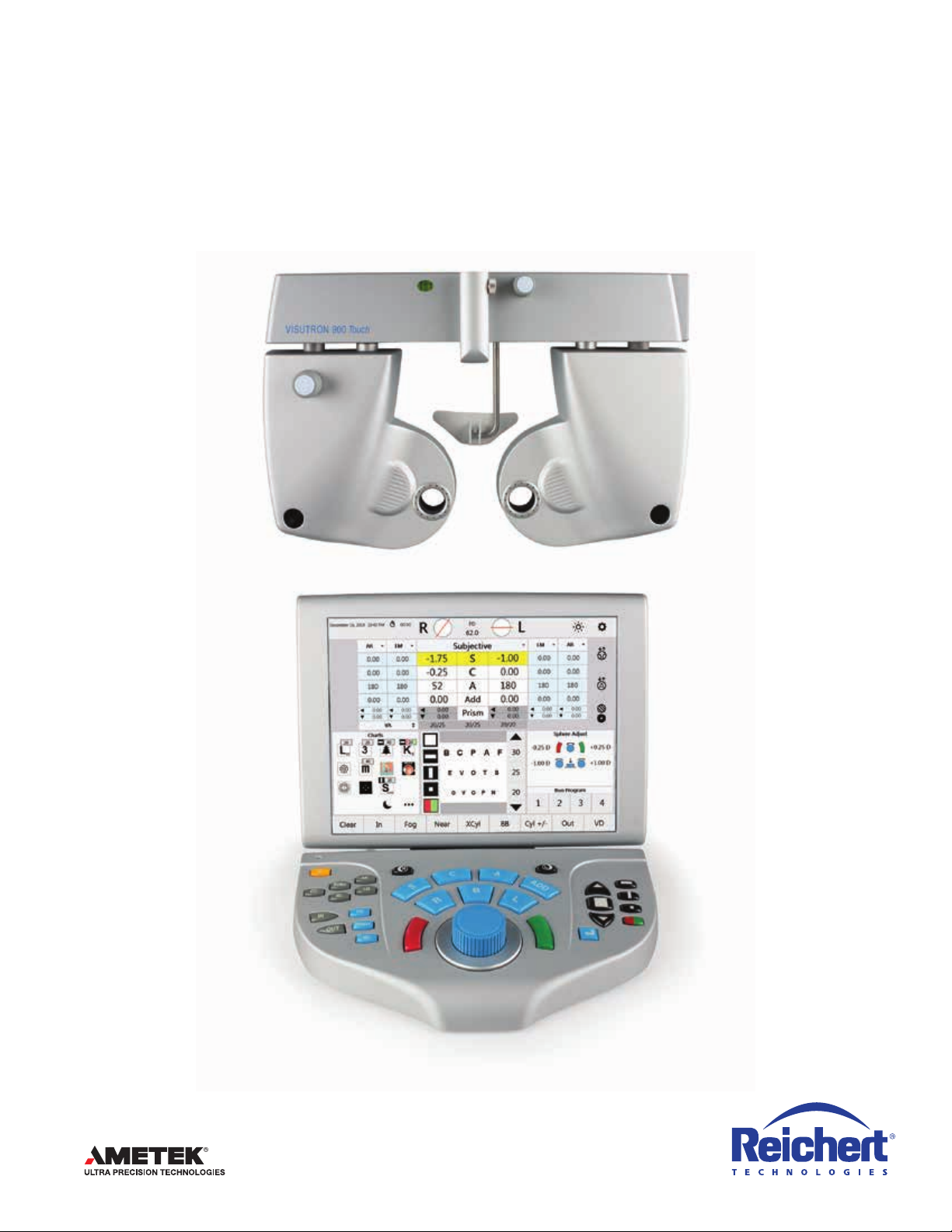
VISUTRON 900 Touch
User’s Guide

©2019 AMETEK, Inc.
Reichert, Reichert Technologies, Phoroptor, and ClearChart are registered trademarks of Reichert, Inc.
LensChek and OptoChek are trademarks of Reichert, Inc.
Bluetooth is a registered trademark of Bluetooth SIG.
AMETEK is a registered trademark of AMETEK, Inc.
All other trademarks are property of their respective owners.
The information contained in this document was accurate at time of publication. Specifications subject to change without notice.
Reichert, Inc. reserves the right to make changes in the product described in this manual without notice and without incorporating those
changes in any products already sold.
ISO 13485 Certified – Reichert products are designed and manufactured under quality processes meeting ISO 13485 requirements.
Refer to IEC 60601-1 for system level information.
No part of this publication may be reproduced, stored in a retrieval system, or transmitted in any form or by any means, electronic,
mechanical, recording, or otherwise, without the prior written permission of Reichert, Inc.
Caution: Federal law restricts this device to sale by or on the order of a licensed practitioner. Rx only.

Table of Contents
Symbol Information................................................................................................................................................ 5
Warnings and Cautions .........................................................................................................................................6
Introduction ............................................................................................................................................................ 8
Instrument Setup ................................................................................................................................................... 9
Unpacking Instructions .................................................................................................................................... 9
PartsIdentication ......................................................................................................................................... 9
Connecting the Visutron 900 Touch System ................................................................................................. 11
Connecting a Right or Left Mount Visutron 900 Touch ................................................................................. 12
Connecting with Cables ................................................................................................................................ 13
Connecting with Bluetooth Dongles .............................................................................................................. 14
Bluetooth Dongle LED Lights Description ..................................................................................................... 16
Connecting with Bluetooth USB (ClearChart 4 Series Only) ........................................................................ 17
EMR Setup .................................................................................................................................................... 19
One-Way EMR ........................................................................................................................................... 19
Two-Way EMR ........................................................................................................................................... 19
Setup .......................................................................................................................................................... 20
Printer ........................................................................................................................................................... 21
Daisy Chaining Multiple Visutron 900 Touch Systems .................................................................................. 22
Connecting with Internal Bluetooth ............................................................................................................ 23
Near Vision Rod and Card ............................................................................................................................ 24
Face Shields ................................................................................................................................................. 24
Turn the Unit On and Off ............................................................................................................................... 24
Controller Keypad ......................................................................................................................................... 25
Lens Buttons .............................................................................................................................................. 26
Chart Buttons ............................................................................................................................................. 27
In & Out Buttons ......................................................................................................................................... 27
Quick Comparison Buttons ........................................................................................................................ 28
Special Function Buttons ........................................................................................................................... 28
Controller Screen .......................................................................................................................................... 29
Top Menu Bar ............................................................................................................................................. 30
Data Fields ................................................................................................................................................. 30
Side Menu .................................................................................................................................................. 30
Acuity Chart Menu ......................................................................................................................................31
Control Knob and Button Functions ........................................................................................................... 31
Program ..................................................................................................................................................... 32
Bottom Menu Bar ....................................................................................................................................... 32
Auxiliary Lenses or Filters .......................................................................................................................... 33
Settings ......................................................................................................................................................... 34
Settings Options ......................................................................................................................................... 34
Programs ................................................................................................................................................... 38
Creating a Program .................................................................................................................................. 38
Clearing a Program .................................................................................................................................. 38
Modifying and Deleting Steps .................................................................................................................. 39
Copying a Program .................................................................................................................................. 39
Exporting a Program ................................................................................................................................ 39
Importing a Program From a USB Drive .................................................................................................. 39
Charts ........................................................................................................................................................ 40
Selecting a Preferred Chart ..................................................................................................................... 40
Default Charts .......................................................................................................................................... 40
Selecting a Default Chart ...................................................................................................................... 40
Performing an Exam ............................................................................................................................................ 41
Aligning the Phoroptor Head ......................................................................................................................... 41
Data Input ..................................................................................................................................................... 42
16243-101 Rev. G
3

Table of Contents (continued)
Inputting Data Electronically ...................................................................................................................... 42
Direct Connection .................................................................................................................................... 43
Imported Data List .................................................................................................................................... 43
Entering Data Manually .............................................................................................................................. 44
Starting a Refraction From Previously Saved, Transferred, or Input Data .................................................... 45
Running a Program ....................................................................................................................................... 45
The Basics .................................................................................................................................................... 46
Eye Selection ............................................................................................................................................. 46
Selecting a Data Field ................................................................................................................................ 46
Adjusting Sphere ........................................................................................................................................ 47
Adjusting Cylinder ......................................................................................................................................47
Adjusting Sphere and Cylinder Together .................................................................................................... 47
Adjusting Axis ............................................................................................................................................. 47
Near Vision Addition ................................................................................................................................... 47
Cross Cylinder .............................................................................................................................................. 48
Examination for Astigmatism ......................................................................................................................48
Manual Test ................................................................................................................................................ 49
Smart Test .................................................................................................................................................. 51
Split Cyl Test .................................................................................................................................................. 53
Binocular Balance ......................................................................................................................................... 54
Near Vision Test ............................................................................................................................................ 55
Fused Cross Cylinder Test ......................................................................................................................... 56
NRA/PRA Test ............................................................................................................................................ 56
Amplitude of Accommodation Test ............................................................................................................. 57
Prism Testing ................................................................................................................................................ 58
Phoria ......................................................................................................................................................... 59
Phoria Testing - Distance ......................................................................................................................... 59
Horizontal Phorias Test ............................................................................................................................ 59
Vertical Phorias Test ................................................................................................................................ 60
Complete the Phoria Test ......................................................................................................................... 60
Phoria Testing - Near ............................................................................................................................... 60
Vergence .................................................................................................................................................... 61
Vergence Testing or Fusion Range Measurement - Distance .................................................................. 61
Power of Divergence ................................................................................................................................ 61
Power of Convergence ............................................................................................................................ 61
Infraergence ............................................................................................................................................. 62
Supravergence ......................................................................................................................................... 62
Vergence Testing or Fusion Range Measurement - Near ........................................................................ 62
Vertex Distance Calculator ............................................................................................................................63
Saving Visual Acuity ...................................................................................................................................... 63
Comparing Refraction Data .......................................................................................................................... 64
EMR and Printing .......................................................................................................................................... 65
Data Output ................................................................................................................................................ 66
Clear ............................................................................................................................................................. 67
Cleaning and Maintenance .................................................................................................................................. 68
Troubleshooting ................................................................................................................................................... 70
Service Menu ................................................................................................................................................ 72
Specications ...................................................................................................................................................... 75
Classications ............................................................................................................................................... 76
Guidance Tables .................................................................................................................................................. 77
Appendix A - Compatibility Chart ......................................................................................................................... 81
Appendix B - Visutron 900 Touch, Lensmeter, and Auto Refractor Data ............................................................. 82
Warranty .............................................................................................................................................................. 83
4 16243-101 Rev. G
Symbol Information
Symbol Information
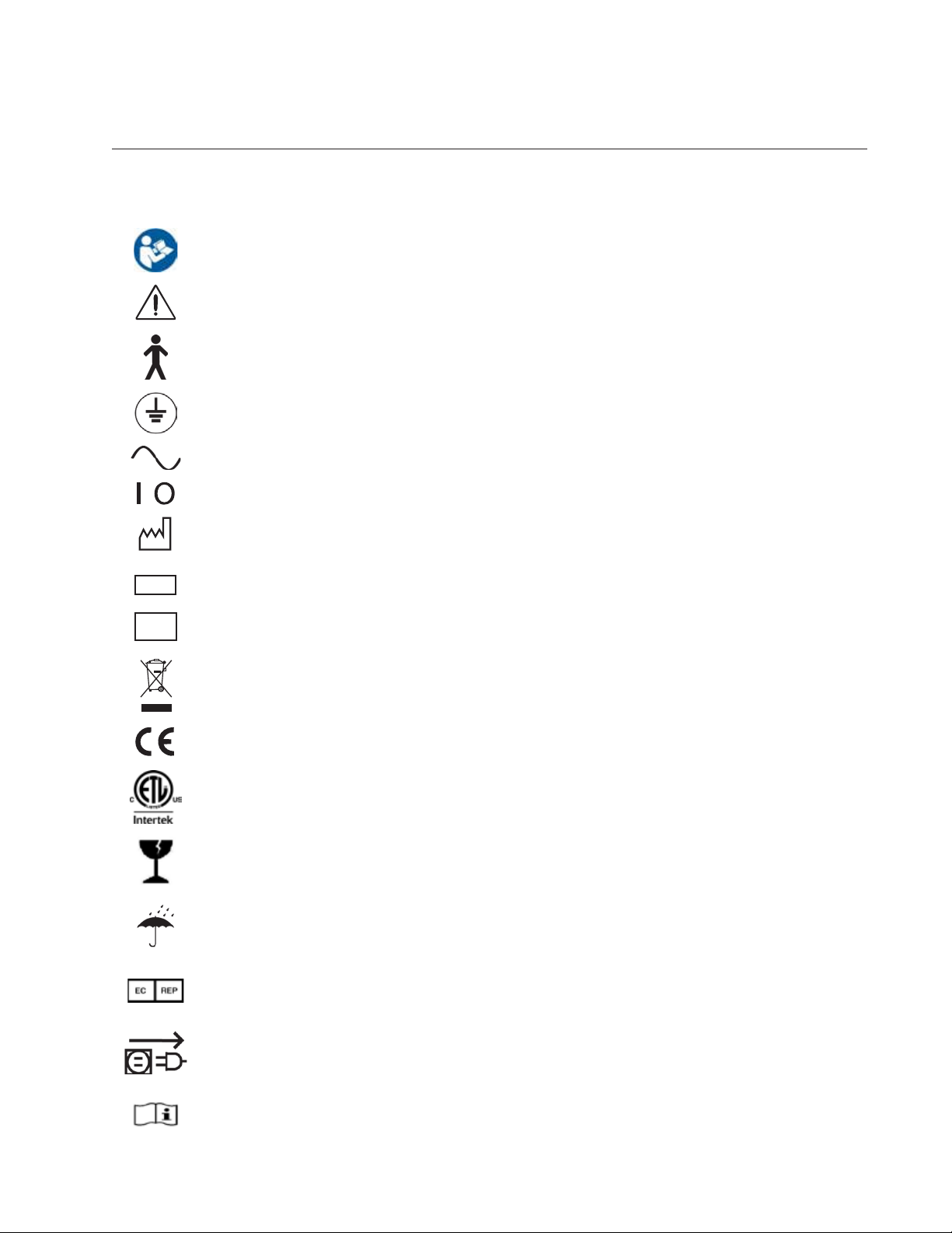
The following symbols appear on the instrument.
Refer to Instruction Manual
Caution
Type B Product Classification
Protective Earth
Alternating Current Power
ON / OFF
2019
REF
SN
Date of Manufacture
Catalog Number
Serial Number
Waste of Electrical and Electronic Equipment
Compliance to Medical Device Directive 93/42/EEC
Authorized to mark given by Intertek ETL Semko for conformance with electrical
standards
Fragile Contents in Shipping Container - handle with care
Keep Dry - Keep package away from rain
Authorized Representative in European Community
Unplug before opening
Operating Instructions
16243-101 Rev. G
5

Warnings and Cautions
Warnings and Cautions
Reichert Technologies® (Reichert®) is not responsible for the safety and reliability of this instrument when
unauthorized dealers or persons assemble, disassemble, repair, or modify the instrument, or when
a person does not use the instrument in accordance with this User’s Guide.
WARNING: AN INSTRUCTION THAT DRAWS ATTENTION TO THE RISK OF INJURY OR DEATH.
WARNING: UNITED STATES FEDERAL LAW AND EUROPEAN REGULATIONS REQUIRE THAT ONLY
A LICENSED PRACTITIONER OR A PERSON ACTING ON BEHALF OF A LICENSED PRACTITIONER
PURCHASE THIS DEVICE.
WARNING: THE OPERATOR OF THIS INSTRUMENT SHOULD USE IT IN STRICT ACCORDANCE WITH THE
INSTRUCTIONS OUTLINED IN THIS USER’S GUIDE. REICHERT TECHNOLOGIES CANNOT GUARANTEE
THE SAFETY OF THE OPERATOR AND THE PERFORMANCE OF THE INSTRUMENT IF THE OPERATOR
USES THE INSTRUMENT IN A MANNER NOT SPECIFIED BY REICHERT TECHNOLOGIES.
WARNING: DO NOT REPAIR OR SERVICE THIS INSTRUMENT WITHOUT AUTHORIZATION FROM THE
MANUFACTURER. EXPERIENCED PERSONNEL OR DEALERS WHO ARE TRAINED BY REICHERT MUST
PERFORM ANY REPAIR OR SERVICE TO THIS INSTRUMENT TO PREVENT SERIOUS INJURY TO THE
OPERATOR OR PATIENT.
WARNING: NO PERSON IS ALLOWED TO MODIFY THIS INSTRUMENT. REICHERT MUST AUTHORIZE ANY
MODIFICATION TO THIS UNIT TO ENSURE CORRECT OPERATION.
WARNING: IF ANY PERSON MODIFIES THIS INSTRUMENT, REICHERT MUST CONDUCT INSPECTION
AND TESTING OF THE INSTRUMENT TO ENSURE ITS CONTINUED SAFE USE.
WARNING: CONNECT THIS EQUIPMENT ONLY TO A SUPPLY MAINS WITH PROTECTIVE EARTH TO
AVOID THE RISK OF ELECTRIC SHOCK AND TO PREVENT DAMAGE TO THE INSTRUMENT AND/OR
INJURY TO THE OPERATOR OR PATIENT.
WARNING: APPLY RATED INPUT VOLTAGE TO THE UNIT AS INDICATED ON THE DATA PLATE TO
PREVENT DAMAGE TO THE INSTRUMENT AND/OR INJURY TO THE OPERATOR OR PATIENT.
WARNING: ONLY PLUG THE INSTRUMENT INTO AN OUTLET WITH AN EARTH GROUND. DO NOT
REMOVE OR DEFEAT THE INSTRUMENT’S EARTH GROUND CONNECTION ON THE POWER INPUT
CONNECTOR OR THE UNIT’S POWER CORD, OR YOU COULD CAUSE DAMAGE TO THE INSTRUMENT
AND/OR INJURY TO THE OPERATOR OR PATIENT.
WARNING: DO NOT USE THE EQUIPMENT OR SYSTEM ADJACENT TO OR STACKED WITH OTHER
EQUIPMENT. IF YOU NEED TO USE ADJACENT OR STACKED EQUIPMENT, OBSERVE THE EQUIPMENT
OR SYSTEM TO VERIFY NORMAL OPERATION IN THE CONFIGURATION IN WHICH YOU USE IT.
WARNING: RISK OF ELECTRIC SHOCK OR FIRE. THIS DEVICE IS NOT INTENDED TO BE USED WITH
LIQUIDS. DO NOT PLACE OR USE OPEN LIQUID CONTAINERS NEAR THE DEVICE, DUE TO THE RISK OF
SPILLAGE OF LIQUID ONTO THE DEVICE.
WARNING: THIS INSTRUMENT IS NOT SUITABLE FOR USE IN THE PRESENCE OF FLAMMABLE
ANESTHETIC MIXTURES, SUCH AS OXYGEN OR NITROUS OXIDE.
WARNING: THE USE OF ACCESSORIES OR CABLES OTHER THAN THOSE SPECIFIED, WITH THE
EXCEPTION OF THOSE SOLD BY THE MANUFACTURER AS REPLACEMENT PARTS FOR THE INTERNAL
COMPONENTS, MIGHT RESULT IN INCREASED EMISSIONS OR DECREASED IMMUNITY OF THE
EQUIPMENT OR SYSTEM.
6 16243-101 Rev. G

Warnings and Cautions (continued)
Warnings and Cautions (continued)
WARNING: PRIOR TO INSTALLING THE PHOROPTOR HEAD ONTO THE STAND ARM, VERIFY THAT THE
ROD ON THE STAND ARM IS SECURE BEFORE ATTEMPTING TO INSTALL THE PHOROPTOR HEAD OR
YOU MIGHT DAMAGE THE UNIT AND/OR INJURE THE PATIENT.
WARNING: OTHER ELECTRICAL OR ELECTRONIC EQUIPMENT CAN INTERFERE WITH THE BLUETOOTH
WIRELESS CONNECTION TRANSMITTERS OR RECEIVERS, EVEN IF THAT EQUIPMENT ALSO COMPLIES
WITH CISPR EMISSIONS REQUIREMENTS.
WARNING: PORTABLE RF COMMUNICATIONS EQUIPMENT (INCLUDING PERIPHERALS SUCH AS
ANTENNA CABLES AND EXTERNAL ANTENNAS) SHOULD BE USED NO CLOSER THAN 30 CM (12
INCHES) TO ANY PART OF THE NSTRUMENT, INCLUDING CABLES SPECIFIED BY THE MANUFACTURER.
OTHERWISE, DEGRADATION OF THE PERFORMANCE OF THIS INSTRUMENT COULD RESULT.
CAUTION: AN INSTRUCTION THAT DRAWS ATTENTION TO THE RISK OF DAMAGE TO THE PRODUCT.
CAUTION: THE INTERNAL CIRCUITRY OF THE INSTRUMENT CONTAINS ELECTROSTATIC DISCHARGE
SENSITIVE DEVICES (ESDS) THAT ARE SENSITIVE TO STATIC CHARGES PRODUCED BY THE HUMAN
BODY. DO NOT REMOVE THE COVERS WITHOUT TAKING PROPER ESDS PRECAUTIONS.
CAUTION: DO NOT USE SOLVENTS OR STRONG CLEANING SOLUTIONS ON ANY PART OF THIS
INSTRUMENT TO ENSURE THAT YOU DO NOT DAMAGE THE UNIT. SEE THE MAINTENANCE SECTION
OF THIS GUIDE FOR DETAILED CLEANING INSTRUCTIONS.
CAUTION: DO NOT USE AMMONIA-BASED CLEANERS ON THE LIQUID CRYSTAL DISPLAY (LCD) TO
ENSURE THAT YOU DO NOT DAMAGE THE DISPLAY. SEE THE MAINTENANCE SECTION OF THIS GUIDE
FOR DETAILED CLEANING INSTRUCTIONS.
CAUTION: MEDICAL ELECTRONIC EQUIPMENT REQUIRES SPECIAL PRECAUTIONS REGARDING EMC
AND IT NEEDS TO BE INSTALLED AND PUT INTO SERVICE ACCORDING TO THE EMC INFORMATION
PROVIDED IN THE ACCOMPANYING DOCUMENTS.
CAUTION: PORTABLE AND MOBILE RF COMMUNICATIONS EQUIPMENT CAN AFFECT MEDICAL
ELECTRICAL EQUIPMENT.
CAUTION: DO NOT USE THIS INSTRUMENT NEAR HIGH-FREQUENCY EMITTING SURGICAL EQUIPMENT.
CAUTION: THIS INSTRUMENT IS NOT INTENDED TO BE CONNECTED TO EQUIPMENT OUTSIDE THE
CONTROL OF REICHERT TECHNOLOGIES OR IT MUST BE TESTED TO APPLICABLE IEC OR ISO
STANDARDS.
CAUTION: DO NOT INSTALL ANY ADDITIONAL SOFTWARE OTHER THAN WHAT IS SUPPLIED WITH THIS
INSTRUMENT. IF YOU INSTALL ADDITIONAL SOFTWARE, IT MIGHT CAUSE UNEXPECTED OPERATION,
RESULTING IN INSTRUMENT MALFUNCTION.
CAUTION: YOU MUST PLUG THIS INSTRUMENT INTO AN OUTLET WITH AN EARTH GROUND THAT IS
CONNECTED TO THE RECEPTACLE TO PREVENT DAMAGE TO THE UNIT. DO NOT DISABLE OR REMOVE
THE GROUND PIN.
CAUTION: INGRESS PROTECTION CLASSIFICATION FOR THE PHOROPTOR HEAD IS IP2X, WHILE
THE CONTROLLER, AND CENTRAL UNIT ARE IP3X. DO NOT SPRAY, SPLASH, OR IMMERSE THESE
INSTRUMENTS IN CLEANING SOLUTIONS.
CAUTION: ELECTROMAGNETIC INTERFERENCE FROM OTHER DEVICES MAY AFFECT THE PERFORMANCE
OR SERVICE LIFE OF THIS INSTRUMENT. IF INTERFERENCE IS PRESENT, TURN OFF OTHER ELECTRONIC
DEVICES, OR REMOVE THEM FROM THE IMMEDIATE AREA WHILE OPERATING THIS INSTRUMENT.
16243-101 Rev. G
7

Introduction
Introduction
Congratulations on your purchase of the Reichert Technologies (hereafter referred to as Reichert)
Visutron 900 Touch.
This User’s Guide is designed as a training and reference manual for operation, maintenance, and
troubleshooting. We recommend that you read it carefully prior to use and follow the instructions in
the guide to ensure optimum performance of your new instrument. Only properly trained eye care
professionals, such as ophthalmologists, optometrists, opticians, and eye care technicians should
operate this instrument. All parts of this Medical Electrical system are suitable for use within the patient
environment.
Please retain this guide for future reference and to share with other users. For additional copies of this
manual or questions related to the Visutron 900 Touch, contact your local authorized Reichert dealer, or
contact our Customer Service department directly:
Tel: 716-686-4500
Fax: 716-686-4555
Email: reichert.information@ametek.com
Indications for Use
The Visutron 900 Touch Digital Refraction System is designed for:
• Subjective measurement of the refractive error of the eye.
• Determination of correction data for refraction anomalies and binocular functions as the basis for
manufacturing eyeglasses and contact lenses.
• Use in refraction rooms in clinics and practices of physicians, optometrists, or opticians.
• ConnectiontoothermedicalexaminationequipmentortoanofceElectronicMedicalRecords
(EMR) system.
• Operation by physicians, optometrists, opticians, or properly trained clinical personnel.
• Installation under the conditions for medical equipment.
• The digital refractor Visutron 900 Touch with Prism is additionally designed for:
• Measurement of ocular deviation in patients with latent or manifest strabismus.
Contra-Indications
• There are none associated with the Visutron 900 Touch Digital Refraction System.
8 16243-101 Rev. G

Instrument Setup
Unpacking Instructions
Great care is taken to deliver the Visutron 900 Touch intact. Please read this User’s Guide before operating
the unit.
We package the instrument in shipping containers to protect the instrument from damage during shipping.
Please carefully remove the Phoroptor Head, Controller, Central Unit, and Accessories Box from the
packaging material.
Note: Please retain the original packaging and use it if future transportation of the instrument is required.
The main components of the Visutron 900 Touch are packed in two separate boxes. The first box contains the
Phoroptor Head and Reading Rod, the second box contains the Central Unit, Controller, and Accessories Box.
Note: The Accessories Box includes a power cord, cable for the Phoroptor Head, Bluetooth antenna for
the Central Unit, ClearChart 4 Bluetooth Adaptor, near vision card and illuminator, face shields, dust
covers for the Phoroptor Head and Controller, and User’s Guide.
Note: If any accessories or parts are missing, immediately contact Reichert.
Parts Identification
One of the following Visutron 900 Touch Systems is in the shipping container, depending on the system speci-
fications ordered.
Systems Without Prisms Systems With Prism
Visutron 900 Touch System - Middle Mount 16243 Visutron 900 Touch System - Middle Mount 16246
Visutron 900 Touch Head Assembly 16222 Visutron 900 Touch with Prism Head Assembly 16223
Central Unit 16219 Central Unit 16219
Controller 16228 Controller 16228
Visutron 900 Touch System - Left Mount 16244 Visutron 900 Touch System - Left Mount 16247
Visutron 900 Touch Head Assembly 16224 Visutron 900 Touch with Prism Head Assembly 16225
Central Unit 16219 Central Unit 16219
Controller 16228 Controller 16228
Visutron 900 Touch System - Right Mount 16245 Visutron 900 Touch System - Right Mount 16248
Visutron 900 Touch Head Assembly 16226 Visutron 900 Touch with Prism Head Assembly 16227
Central Unit 16219 Central Unit 16219
Controller 16228 Controller 16228
The following accessories are included in all Visutron 900 Touch Systems:
Item REF Item REF
User’s Guide - German 16243-101-GER Dust Cover – Phoroptor Head 559-153
Power Cord 230V WCBL10027 Dust Cover – Controller 16217-029
Phoroptor Cable - Middle Mount 559-275 Near Bright Illuminator Kit 16200-869
Phoroptor Cable - Left/Right Mount 559-276 Face Shield Kit (2 sets) 16200-835
ClearChart 4 Bluetooth Adapter 13779
The following optional accessories are available for use with the Visutron 900 Touch System:
Item REF Item REF
Decimal Near Vision Kit 16237 Snellen Near Vision Kit 16236
Extension Cable (15ft),
Visutron 900 Touch Head or Controller
Thermal Printer 16230 Cables and Bluetooth Dongle Kits (Various)
Phoroptor Cable - Left/Right Mount 559-276 Snellen Card Holder 16231
Decimal Card Holder 16235 Card Beam Assembly 11636-860
16243-101 Rev. G
16213-432 Extension Cable (25ft),
Visutron 900 Touch Head or Controller
16213-433
9
Instrument Setup (continued)
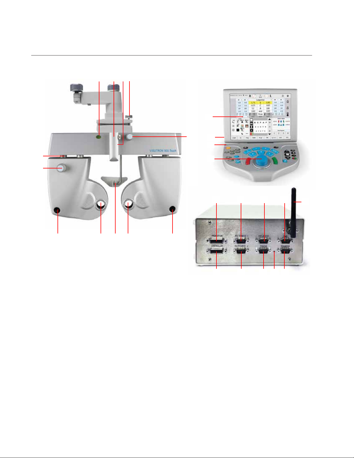
Parts Identification (continued)
21 3 4
Controller
6
24
23
22 2121
Phoroptor Head
Figure IS-01, Parts Identication
5
2020
7
8
9
Central Unit
10
19
11
18
13
171216 15
14
1. Illuminated Bubble Level & Power Indicator Light
2. Threaded Screw for Near Vision Rod
3. Convergence Lever
4. Leveling Thumb Screw
5. Vertex Distance Adjustment Knob
6. Touch Screen Display
7. USB Port (on back)
8. Power Indicator Light
9. Control Knob
10. Phoroptor Head Connection Port
11. Instrument 1 Connection Port for connecting
pre-test equipment
12. Projector Connection Port
10 16243-101 Rev. G
13. EMR Connection Port for connecting to a computer
14. Wireless Antenna
15. Transfer Port for Daisy Chaining
16. Power Indicator Light
17. Printer Connection Port
18. Instrument 2 Connection Port for connecting pretest equipment
19. Controller Connection Port
20. Corneal Vertex Distance Windows
21. Lens Apertures
22. Forehead Rest
23. Asymmetrical Height Adjustment Knob
24. Mid Position Height Marking
Instrument Setup (continued)
Connecting the Visutron 900 Touch System
WARNING: APPLY RATED INPUT VOLTAGE TO THE UNIT AS INDICATED ON THE DATA PLATE TO PREVENT
DAMAGE TO THE INSTRUMENT AND/OR INJURY TO THE OPERATOR OR PATIENT.
WARNING: CAREFULLY ARRANGE THE CABLES FOR THE UNIT AND ACCESSORIES, SO THE CABLES DO NOT
PRESENT A TRIPPING HAZARD TO THE EXAMINER OR A DANGER TO THE PATIENT.
WARNING: POSITION THIS INSTRUMENT SO THE PLUG IS EASILY ACCESSIBLE.
WARNING: DO NOT PLUG IN THE CENTRAL UNIT UNTIL THE VISUTRON 900 TOUCH SYSTEM IS FULLY SETUP.
The basic system setup contains three components programmed to interact with each other: the
Phoroptor Head, the Central Unit, and the Controller. The Central Unit directs communication between
the Phoroptor Head, Controller, and other pre-test devices, while the Controller acts as the user interface
and controls the Phoroptor Head and the Input/Output of data.
The Visutron 900 Touch is also designed to communicate with Reichert and other manufacturers acuity
systems.
External devices, including digital acuity systems, projectors, Lensmeters, Auto Refractors, printers, and
computers are connected using serial cables or Bluetooth wireless serial adapters.
Note: Ensure that the pre-test equipment being interfaced is compatible. Refer to Appendix A for a
complete list of external devices that communicate with the Visutron 900 Touch.
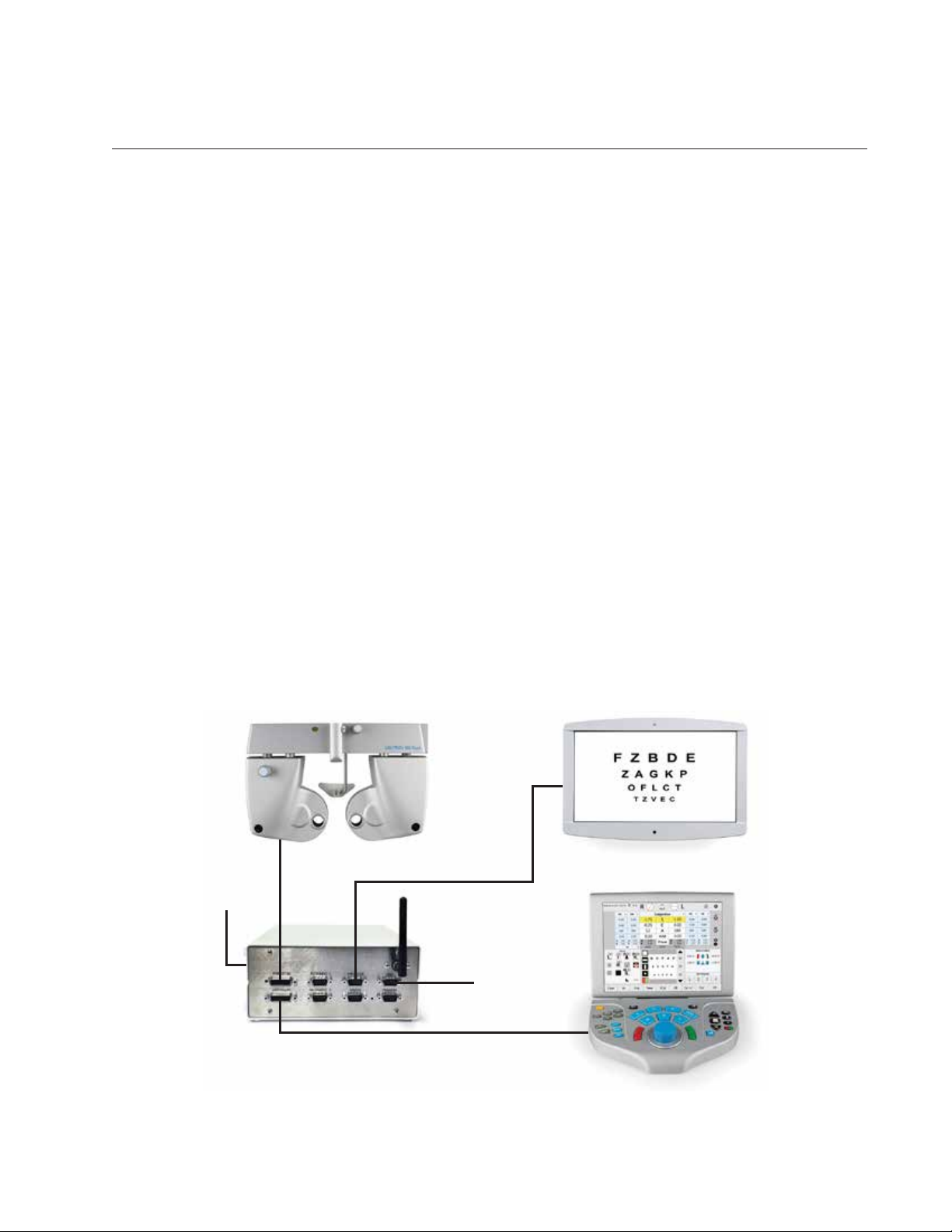
Please refer to the Connection Diagram below for plug and cable layout.
Phoroptor Head
Power
EMR
Central Unit
Projector or Digital Acuity System
16243-101 Rev. G
Controller
Figure IS-02, Connection Diagram
11
Instrument Setup (continued)
Connecting the Visutron 900 Touch System (continued)
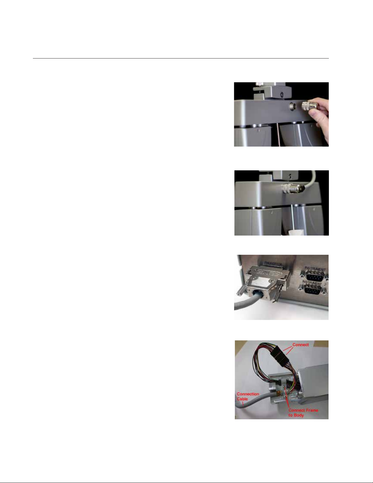
1. Align the pins in the Phoroptor Cable with the Phoroptor head.
RefertogureIS-03.
2. Connect the cable by turning the metal collar clockwise until it is
fullysecure.RefertogureIS-04.
3. Connect the other end of the Phoroptor Cable to the Phoroptor
port in the Central Unit. Refer to Figure IS-05.
4. Connect the built-in cable on the Controller to the Controller port
on the Central Unit.
5. Connect the Power Cord to the Central Unit, then plug in the
power cord to an outlet providing appropriate voltage. Turn the
unit on by turning the ON/OFF switch to ON.
6. Connect the Projector to the Projector port on the Central Unit in
one of the following ways.
a. Refer to the Connecting with Cables section if connecting
with cable.
b. Refer to the Connecting with Bluetooth Dongles section if
connecting with Bluetooth.
c. Refer to the Connecting With Bluetooth USB (ClearChart 4
Series Only) section if connecting with Bluetooth USB.
7. Connect Lensmeters or Auto Refractors to the Instrument 1 or
Instrument 2 ports on the Central Unit in one of the following
ways.
a. Refer to the Connecting with Cables section if connecting
with cable.
b. Refer to the Connecting with Bluetooth Dongles section if
connecting with Bluetooth.
8. Connect a computer to the EMR port on the Central Unit in one
of the following ways. Refer to the EMR Setup section for setup
instructions.
a. Refer to the Connecting with Cables section if connecting
with cable.
b. Refer to the Connecting with Bluetooth Dongles section if
connecting with Bluetooth.
9. If needed, connect the Transfer port to another Visutron 900
Touch in one of the following ways to send data from one device
to another. Refer to the Daisy Chaining Multiple Visutron 900
Touch’s section for instructions.
a. Refer to the Connecting with Cables section if connecting
with cable.
b. Refer to the Connecting with Bluetooth Dongles section if
connecting with Bluetooth.
c. Refer to the Connecting with Internal Bluetooth section if
connecting with Bluetooth.
Figure IS-03, Phoroptor Cable
Figure IS-04, Phoroptor Connected
Figure IS-05, Phoroptor Connected
Connecting a Right or Left Mount Visutron 900 Touch
Connect the Visutron 900 Touch using the connection cable (559-276)
according to Figure IS-05A.
12 16243-101 Rev. G
Figure IS-05A, Connection Diagram
Instrument Setup (continued)
Connecting with Cables
The Visutron 900 Touch can connect to multiple Pro-
jectors, Lensmeters, and Autorefractors easily with a
wired connection. Refer to the instructions below to
connect instruments with a cable.
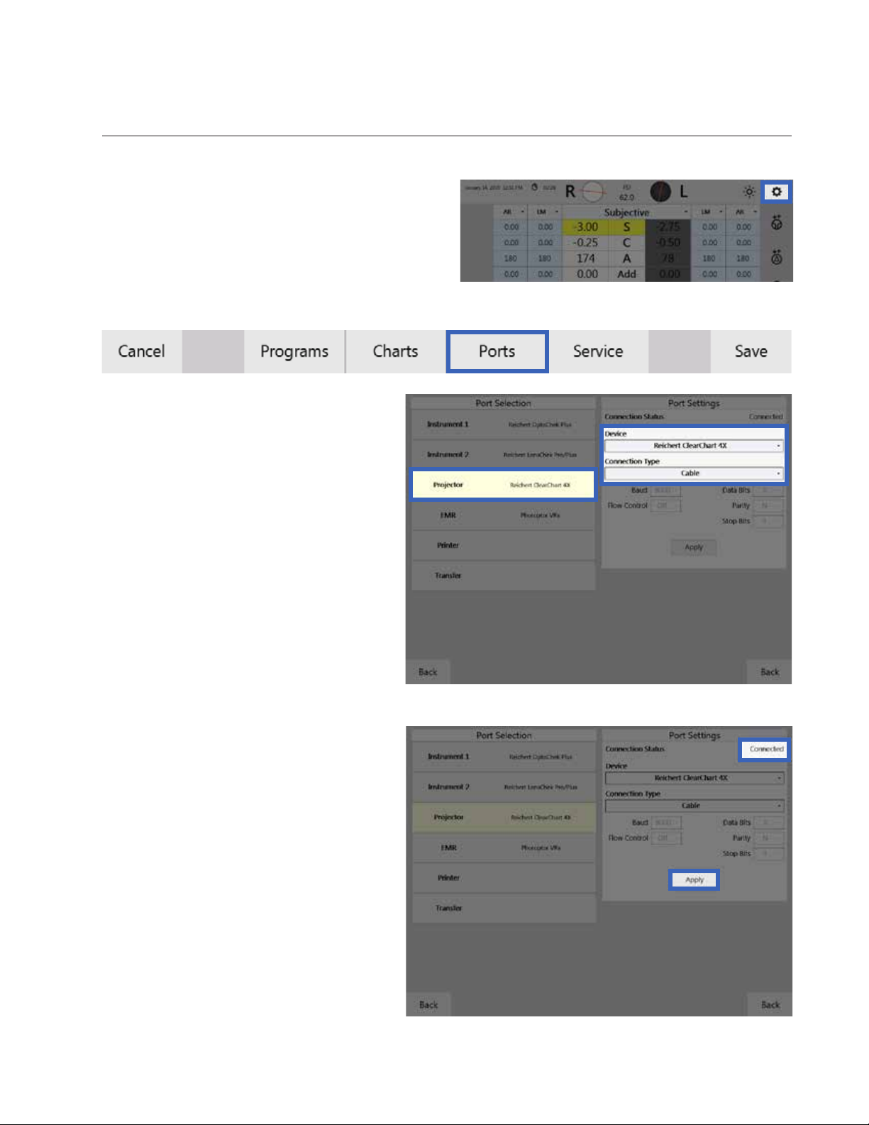
1. Tap Settings, located at the top right of the
Controller screen. Refer to Figure IS-06
2. Tap Ports in the Settings menu.
3. In the Port Selection panel, tap the
portbeingcongured(e.g.,Projector,
Instrument 1, etc). Refer to Figure IS-
07.
4. In the Port Settings panel, select the
device being connected from the dropdown menu. Refer to Figure IS-07.
5. Set the Connection Type to Cable.
Refer to Figure IS-07.
6. If storing or transferring of data is
needed, check the corresponding
boxes. Refer to the Daisy Chaining
Multiple Visutron 900 Touch’s section
of this manual for more information on
these two options.
7. If available, set the serial
communication parameters to match
the settings on the device being
connected.
8. Tap Apply. “Connected” should appear
in the top right. Refer to Figure IS-08.
Figure IS-06, Settings
Figure IS-07, Port Settings Screen
16243-101 Rev. G
Figure IS-08, Port Settings Screen
13
Instrument Setup (continued)
Connecting With Bluetooth Dongles
Reichert developed a Bluetooth dongle to connect external devices wirelessly to the Visutron 900 Touch.
To communicate properly, the Bluetooth dongle must be paired with a specific port on the Central Unit.
Perform the following steps in order to configure each Bluetooth dongle.
Note: Do not connect the Bluetooth dongle to the
power cord until directed to.
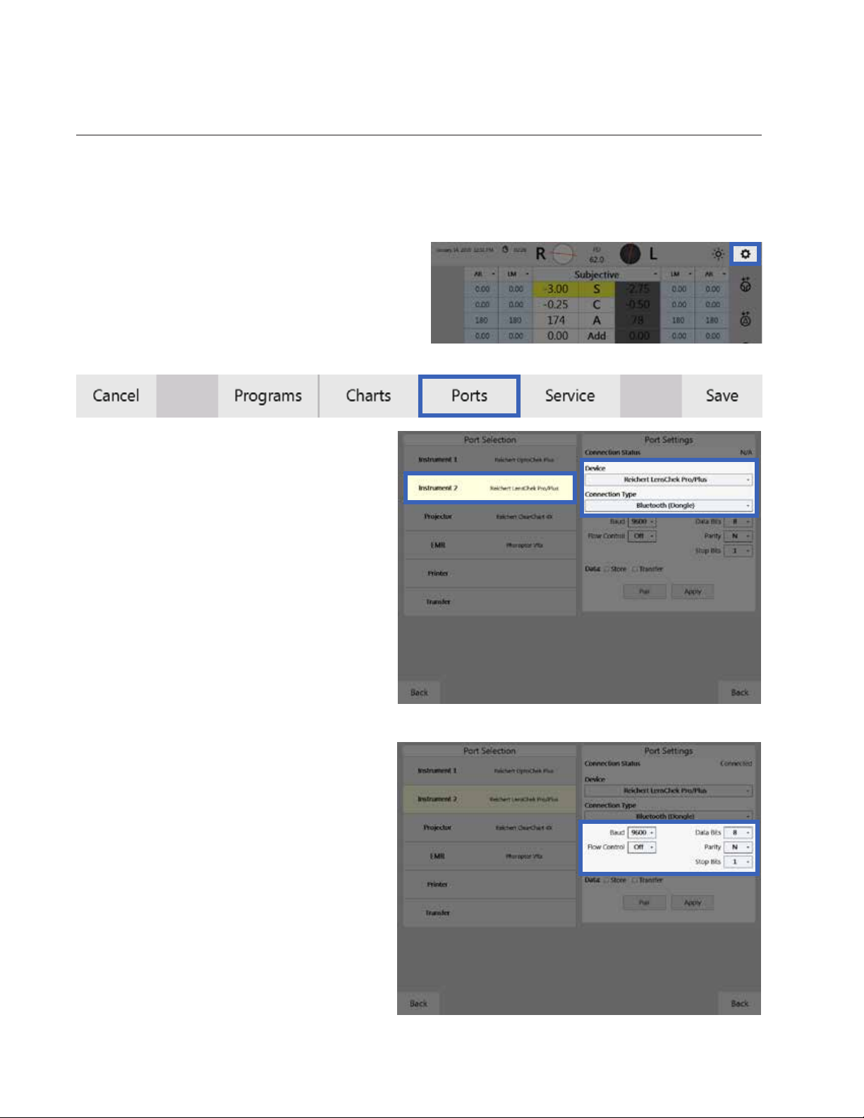
1. Tap Settings, located at the top right of the
Controller screen. Refer to Figure IS-09.
2. Tap Ports in the Settings menu.
3. In the Port Selection panel, tap the
portbeingcongured(e.g.,Projector,
Instrument 1, etc). Refer to Figure IS-10.
4. In the Port Settings panel, select the
device being connected from the dropdown menu. Refer to Figure IS-10.
5. Set the Connection Type to Bluetooth
(Dongle). Refer to Figure IS-10.
6. If storing or transferring of data is needed,
check the corresponding boxes. Refer to
the Daisy Chaining Multiple Visutron 900
Touch’s section of this manual for more
information on these two options.
7. If available, set the serial communication
parameters to match the settings on the
device being connected. Refer to Figure
IS-11.
Figure IS-10, Port Settings Screen
Figure IS-09, Settings
Figure IS-11, Serial Communication Parameters
14 16243-101 Rev. G
Instrument Setup (continued)
Connecting With Bluetooth Dongles (continued)
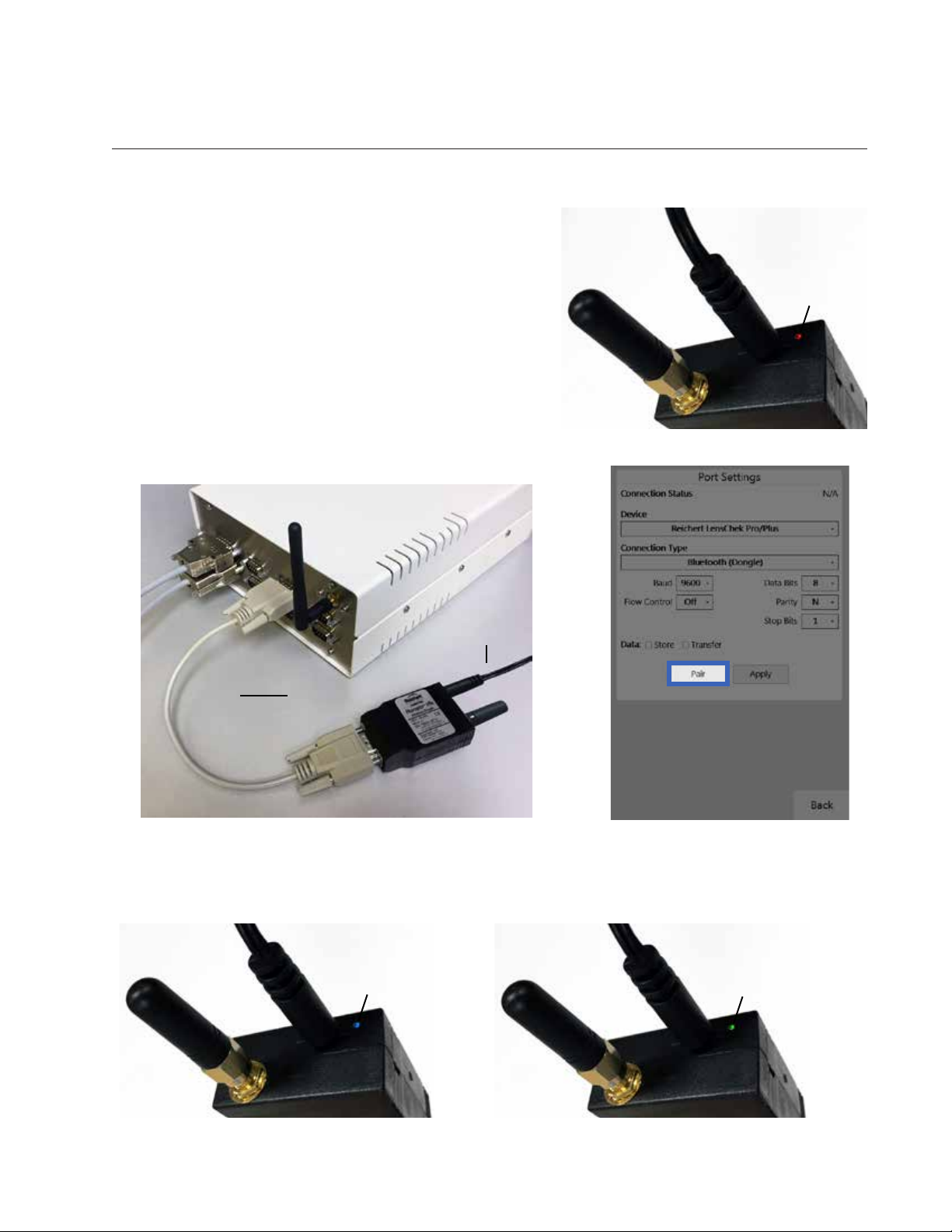
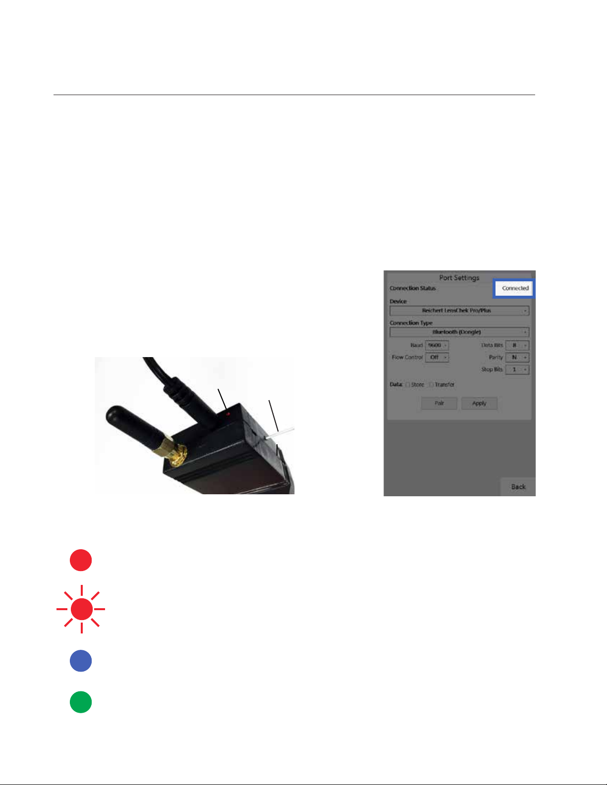
8. Connect the Bluetooth dongle to the power adapter
provided. The LED should illuminate red, indicating it is
ready to be paired. Refer to Figure IS-12.
9. Connect the Bluetooth dongle to the corresponding
Central Unit port with the provided pairing cable. Refer to
Figure IS-13.
10. In the Port Settings panel on the Visutron 900 Touch
controller tap Pair. Refer to Figure IS-14.
CAUTION: DO NOT TAP PAIR AGAIN. IF PAIR IS ACTIVATED,
IT WILL BE NECESSARY TO REPEAT THE ABOVE PROCEDURE TO RE-ESTABLISH THE WIRELESS CONNECTION.
Red Light
Figure IS-12, Ready to Pair
Power
Cord
Pairing
Cable
Bluetooth
Dongle
Figure IS-13, Bluetooth Dongle to Central Unit
11. While connecting, the LED will illuminate blue. Do not disconnect the dongle. Refer to Figure IS-15.
12. Once the connection has been established, the LED will illuminate green. Refer to Figure IS-16.
Blue Light
Figure IS-14, Pair Button
Green Light
Figure IS-15, Actively Pairing
16243-101 Rev. G
Figure IS-16, Connected
15
Instrument Setup (continued)
Connecting With Bluetooth Dongles (continued)
Note: The LED will blink red if the connection fails.
Note: If the Bluetooth dongle was successfully paired, “Connected” will appear in the upper right
corner of the panel. Refer to Figure IS-18. If “Failed” appears, then press and hold the Bluetooth
dongle’s reset switch, using an appropriate object (e.g., paperclip) for approximately 2 seconds.
The reset switch is on the side of the Bluetooth dongle. Refer to Figure IS-17. The LED will
illuminate solid red. Repeat the directions starting with step 10.
13. Disconnect the power cord and pairing cable from the Bluetooth dongle.
14. Connect the Bluetooth dongle to the external device’s serial port using the appropriate serial cable
and/or adaptor using the corresponding cable, then power on using the power adaptor. The LED will
illuminate blue.
15. Once the connection has been established again, the LED
will remain green.
Note: At this point the Central Unit and Bluetooth dongle
may be powered off and on in any order. The wireless
connection will be established automatically once both
devices are powered on.
Red
Light
Figure IS-17, Reset the Dongle
Paperclip
Bluetooth Dongle LED Lights Description
Solid Red
Light
Blinking Red
Light
Solid Blue
Light
• No connection.
• Ready to be paired
• Pairing Failed
• Reset Dongle and try to pair again
• Connection In Progress.
• Do not disconnect dongle from Central Unit
Figure IS-18, Connected Status
Solid Green
Light
16 16243-101 Rev. G
• Dongle successfully paired

Instrument Setup (continued)
Connecting With Bluetooth USB (ClearChart 4 Series Only)
Reichert has a Bluetooth USB option
to connect a ClearChart 4, 4X, or 4P
to the Visutron 900 Touch. In order
to establish wireless communications
between the Visutron 900 Touch and
a ClearChart, the Projector port must
first be paired to the Bluetooth USB
adapter.
1. Ensure the ClearChart is turned
off before pairing.
2. Tap Settings, located at the top
right of the Controller screen.
3. Tap Ports on the Settings menu.
4. In the Port Selection panel, tap
Projector.
5. In the Port Settings panel, select
the ClearChart model from the
device list.
Figure IS-19, Device & Connection Type
Note: The Bluetooth USB is only
compatible with the ClearChart 4,
4X or 4P.
6. Set the Connection Type to Blue-
tooth (USB). Refer to Figure IS-19.
7. Install the Bluetooth USB into the
ClearChart.
8. Turn the ClearChart ON.
Note: The Bluetooth USB must be
installed in the ClearChart before the ClearChart is powered ON or the Bluetooth USB will not be
paired properly.
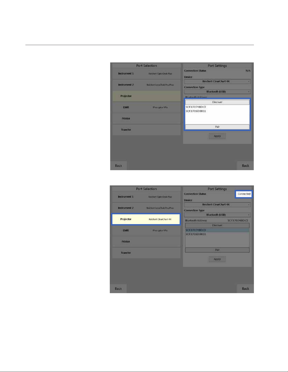
9. Press the Menu button on the ClearChart remote and view the Bluetooth address in the lower right
corner of the ClearChart. Refer to Figure IS-20.
10. Tap Discover on the Ports page and the Visutron 900 Touch will search for all available ClearChart
Digital Acuity Systems. Refer to Figure IS-19.
Figure IS-20, Bluetooth Address
16243-101 Rev. G
17
Instrument Setup (continued)
Connecting With Bluetooth USB (ClearChart 4 Series Only) (continued)
Note: If the desired Bluetooth
USB device is not found,
tap the Discover button
again.
11. Once the Bluetooth address is
displayed, select the address
that matches the address on the
ClearChart and tap Pair. (Tapping Apply is not needed.) Refer
to Figure IS-21.
12. Press the Menu button on the
ClearChart remote to exit the
menu.
Note: The Visutron 900
Touch will only display
‘Initializing Device’ until
the ClearChart menu
is exited. Once the
ClearChart is displaying
a chart, only then can
the Bluetooth connect
and Connected will
appear. Refer to Figure
IS-22 .
Figure IS-21, USB Address & Pair
13. If pairing is unsuccessful, check
all the connections and repeat
the steps in this section.
Figure IS-22, ClearChart Connected
18 16243-101 Rev. G
Instrument Setup (continued)
EMR Setup
The Visutron 900 Touch can connect to an EMR system one of two ways, depending on the capability of
the EMR system. Contact the EMR company to find out if the specific EMR system is configured to support one-way or two-way communication.
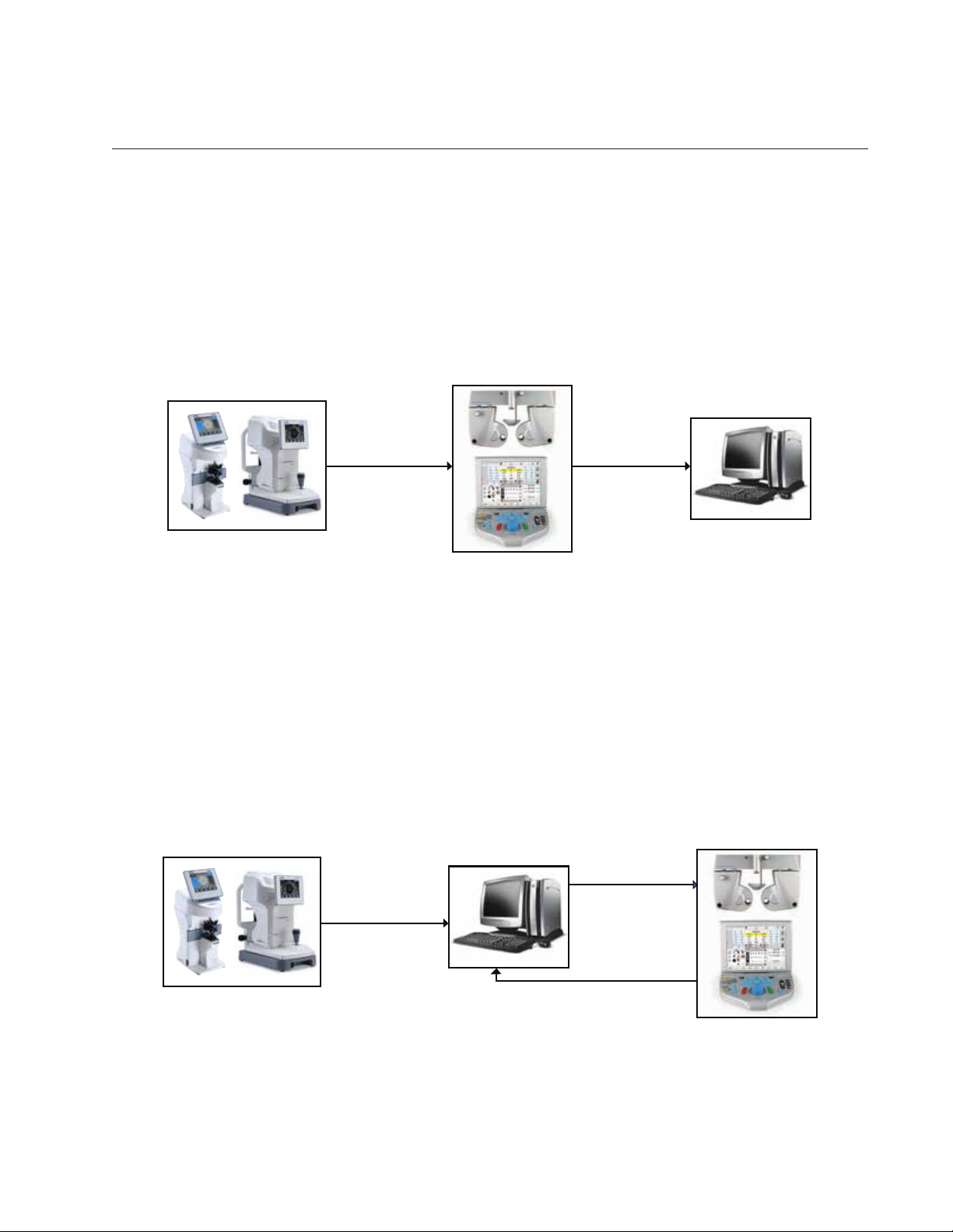
One-Way EMR
One-way communication means the EMR system can only accept data coming in. This configuration requires pre-test equipment to send data to the Visutron 900 Touch, then all of the data (the pre-test data
and final refraction data) would transfer to the EMR. Refer to Figure IS-23.
Pre Test Data goes
TO
the
Visutron 900
Touch
All Data Goes
TO
the EMR
Figure IS-23, One-Way Communication Diagram
Note: If there are multiple lanes with Visutron 900 Touch systems, they will need to be connected via
daisy-chaining. This will allow all pre-test data to be transferred to each Visutron 900 Touch
system. From there, each Visutron 900 Touch can load the pre-test data and send all of the data
to the EMR system. Refer to the Daisy chaining Multiple Visutron 900 Touch’s section for more
detailed information on this setup.
Two-Way EMR
Two-way communication means the EMR can send pre-test data out to the Visutron 900 Touch and
receive final refraction data in from the Visutron 900 Touch. At the end of the exam, the Visutron 900
Touch will send only final refraction data out to the EMR. Refer to Figure IS-24.
Pre Test Data Goes
FROM
Pre Test Data Goes
TO
the EMR
ONLY Final Refraction Data Goes
TO the EMR
the EMR
TO
the Visutron 900
Touch
16243-101 Rev. G
Figure IS-24, Two-Way Communication Diagram
19
Instrument Setup (continued)
EMR Setup (continued)
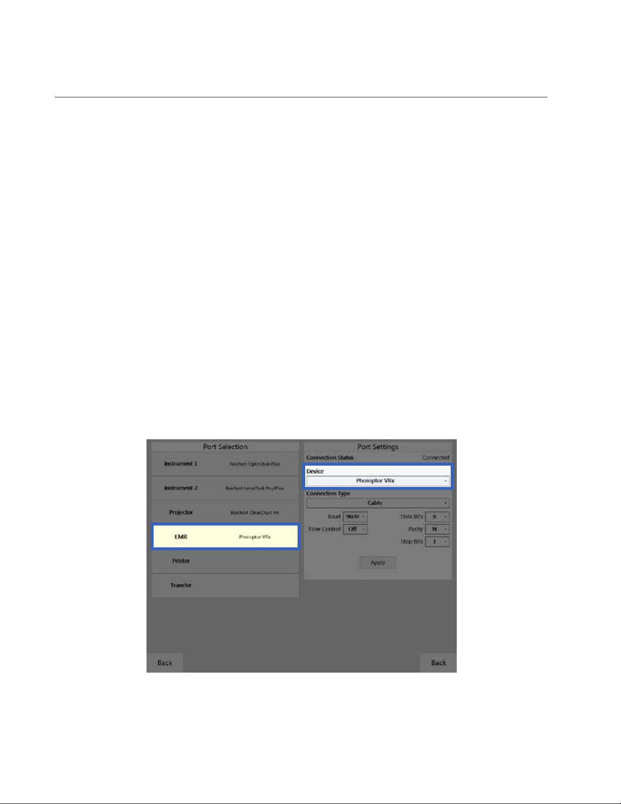
Setup
1. Tap Settings, located at the top right of the Controller screen.
2. Tap Ports on the Settings menu.
3. In the Port Selection panel, tap EMR. Refer to Figure IS-25.
4. In the Port Settings panel, select the device according to the list below.
Devices
Visutron 900 Touch - Sends Visutron 900 Touch final refraction data only (including subjective re-
fraction data and binocular test results).
Visutron 900 Touch Exp - Sends Visutron 900 Touch final refraction data (including subjective re-
fraction data and binocular test results) and pre-test data.
AutoPhor - Sends Visutron 900 Touch final refraction data only.
AutoPhor Exp - Sends Visutron 900 Touch final refraction data and pre-test data.
Vis900 - Sends data in original Visutron 900+ format, for Visutron 900 units only.
5. Connect the computer to the EMR port on the Central Unit with a cable or Bluetooth dongle.
a. Refer to the Connecting with Cables section if connecting with a cable.
b. Refer to the Connecting with Bluetooth Dongles section if connecting with Bluetooth.
6. Set the serial communication parameters to match the settings of the computer serial port.
7. Tap Apply.
Figure IS-25, Port Settings Screen
20 16243-101 Rev. G

Instrument Setup (continued)
Printer
1. Tap Settings, located at the top right of the Controller screen.
2. Tap Ports on the Settings menu.
3. In the Port Selection panel, tap Printer. Refer to Figure IS-27.
4. In the Port Settings panel, select the MCP1000. Refer to Figure IS-27.
5. Connect an MCP1000 printer to the system with a cable or Bluetooth dongle.
a. Refer to the Connecting with Cables section if connecting with a cable.
b. Refer to the Connecting with Bluetooth Dongles section if connecting with Bluetooth.
6. Select the Device driver in the Ports Settings panel and tap Apply.
7. Select the data to print in the Output Options in the
Settings menu, in the lower right corner of the screen.
Refer to Figure IS-26. The data printing options
include:
• Subj, AR, and LM values
• Visual Acuity, FCC, NRA/PRA, Accommodation,
Phoria, and Vergence value
The Print Format drop-down list options include:
• Far • Far/Near
• Near • Far/Add
Figure IS-27, Printer Settings
Figure IS-26, Printing Options
16243-101 Rev. G
21
Instrument Setup (continued)
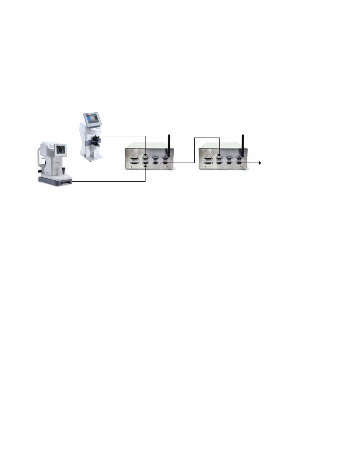
Daisy Chaining Multiple Visutron 900 Touch Systems
When an EMR system only supports one way communication in a setup with multiple Visutron 900
Touch units, Daisy chaining is required to get the pre-test data to all of the Visutron 900 Touch units. Pretest equipment is sent to the first Visutron 900 Touch in the chain, and the data is then sent to all of the
other Visutron 900 Touch systems via the Instrument 1 or 2 and Transfer ports as shown in Figure IS-28.
Lensmeter Data Goes
Autorefractor Data Goes
TO
Instrument 2 Port
TO
Instrument 1 Port
Visutron 1
Instrument 1 Port
Data Goes
OUT
Transfer Port
Data Goes
IN
Visutron 2
Data Goes
OUT
Transfer Port
To Next Visutron 900 Touch
Instrument 1 Port
Figure IS-28, Daisy Chain Setup Diagram
1. Tap Settings, located at the top right of the Controller screen.
2. Tap Ports on the Settings menu.
3. Setup the Auto Refractor and Lensmeter to communicate with the Visutron 900 Touch closest to that
location, using the Instrument 1 and Instrument 2 ports. Refer to the Connecting the Visutron 900
Touch System section of this manual for setup instructions for the pre-test equipment.
4. For both Instrument 1 and Instrument 2 section of the Ports page, check off both Store and Transfer
in the Port Settings panel.
5. Connect the Transfer port on Central Unit of the first Visutron 900 Touch to the Instrument 1 Port
on the Central Unit of the Visutron 900 Touch next in line, using a cable, Bluetooth dongle, or internal
Bluetooth connection. Refer to Figure IS-28.
a. Refer to the Connecting with Cables section if connecting with a cable.
b. If connecting with Bluetooth dongles, refer to the Connecting With Bluetooth Dongles section of
this manual.
c. If connecting with internal Bluetooth, refer to the Connecting With Internal Bluetooth section of this
manual.
Note: TheTransferportontherstVisutron900Touch is the data output port, and the Instrument 1
port on the next Visutron 900 Touch is the data input port.
6. IntherstVisutron900Touch of the chain, for the Transfer port of the Port Settings panel, select
VRx Transfer as the device, then tap Apply.
7. In the second Visutron 900 Touch in the chain, for the Instrument 1 port of the Port Settings panel,
select AutoPhor Receive as the device then tap Apply. For the Transfer port of the Port Settings
panel, select VRx Transfer as the device, then tap Apply.
8. Continue this process until all exam rooms with Visutron 900 Touch systems are connected.
Note: The last Visutron 900 TouchinthechaindoesnotneedtohavetheTransferportcongured,
only the Instrument 1 port. Under Instrument 1, the Transfer box does not need to be checked
off, only the Store box.
Note: There is no limit to the number of Visutron 900 Touch units that can be linked together.
22 16243-101 Rev. G
Instrument Setup (continued)
Daisy Chaining Multiple Visutron 900 Touch’s (continued)
Connecting with Internal Bluetooth
1. Tap Settings, located at the top right of the Controller screen.
2. Tap Ports on the Settings menu.
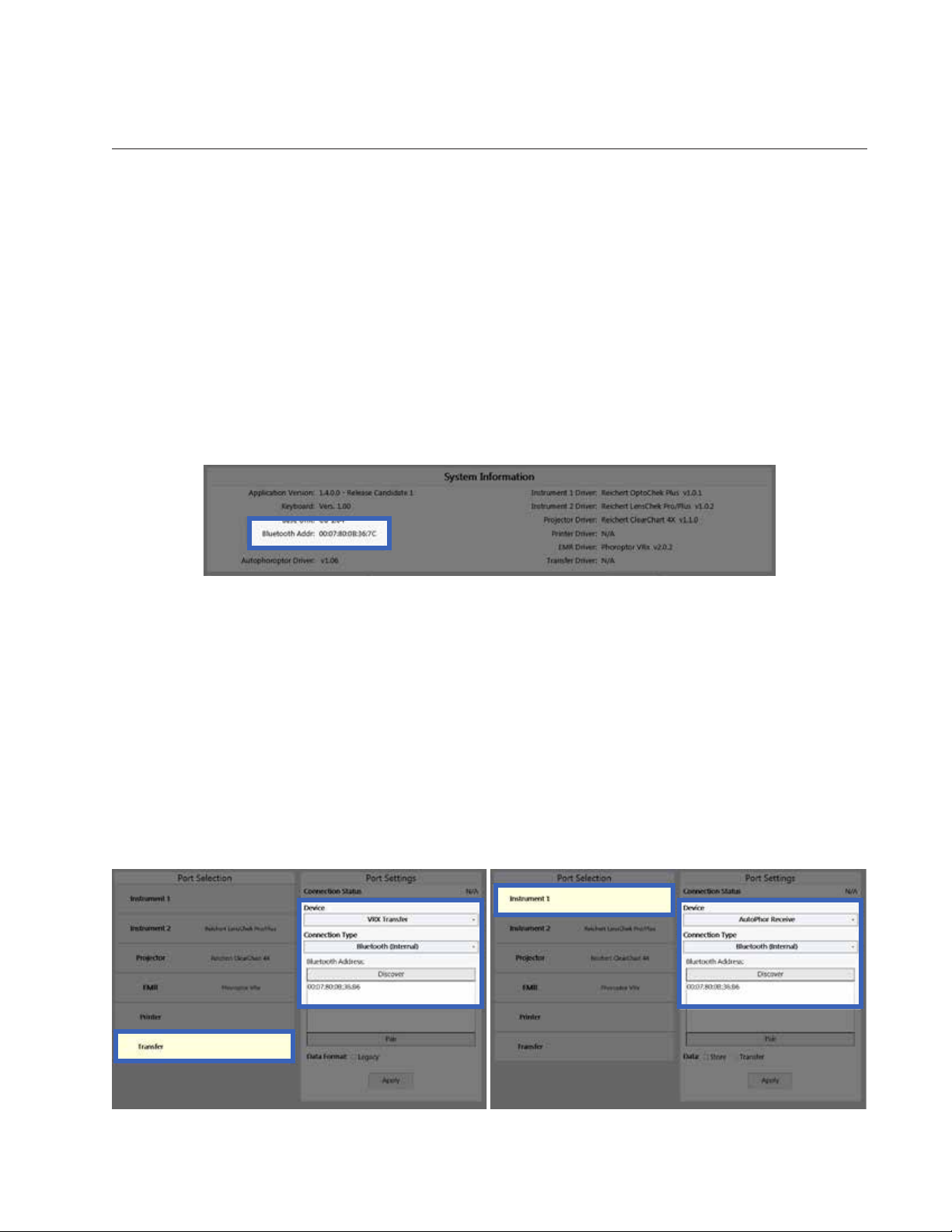
3. In the Port Settings panel, tap Transfer in the Port Selection column. Be sure that under Device,
VRx Transfer is selected. Refer to Figure IS-30.
4. Select Bluetooth (Internal) under Connection Type. Refer to Figure IS-30.
5. Tap Discover under Bluetooth Address. Refer to Figure IS-30.
6. Tap the Bluetooth address for the Visutron 900 Touch that the data will be transferred to, then tap Pair.
Note: The Bluetooth address is found in System Information, in the Service Menu. Refer to Figure IS-29.
Figure IS-29, Bluetooth Address
7. Repeat all the above steps for the Instrument 1 port on the Visutron 900 Touch that is having the data
transferred to it. Be sure that under Device, AutoPhor Receive is selected. Refer to Figure IS-31.
8. Repeat these connection steps for every Visutron 900 Touch in the chain.
Note: If the Bluetooth was successfully paired, “Connected” will appear in the upper right corner of
the panel on both Visutron 900 Touch units. “Connected” will not appear until both Visutron 900
Touch’sarecongured.If“Failed”appearsoneitherVisutron900Touch instruments, then repeat
the directions from step 3.
Note: ThelastinstrumentinthechainonlyneedstohavetheInstrument1portcongured,andnotthe
Transfer port.
Figure IS-30, Internal Bluetooth Transfer
16243-101 Rev. G
Figure IS-31, Internal Bluetooth Receive
23
Instrument Setup (continued)
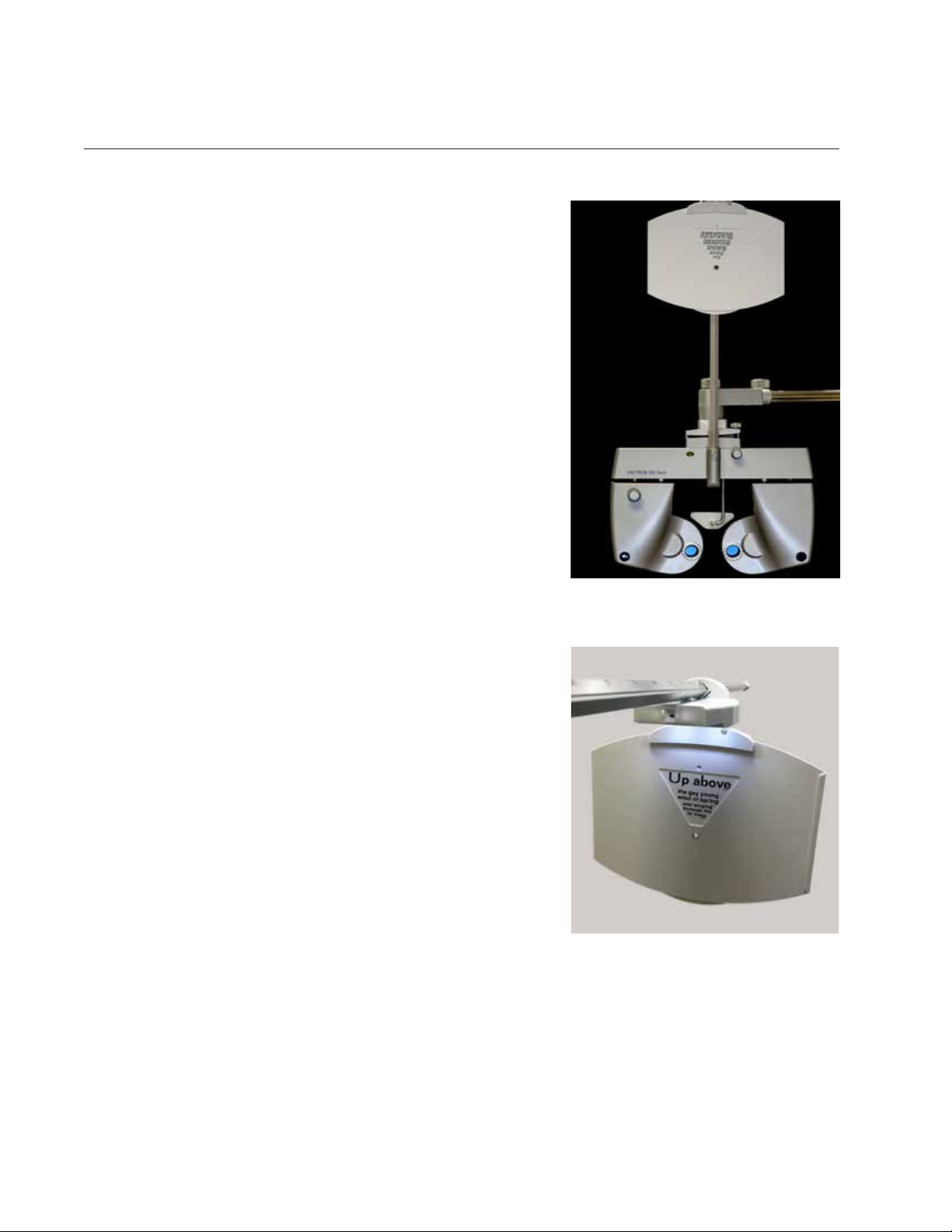
Near Vision Rod and Card
The Visutron 900 Touch includes a Near vision rod, and a near
vision card attached to a card illuminator. Place the three AAA
batteries in the card illuminator.
Slide the card illuminator onto the near vision rod. Loosen
the convergence lever thumb screw, install the rod into the
convergence lever, and tighten the thumb screw. The reading
rod is held up in the stored position by a spring clip.
Use caution when moving the Visutron 900 Touch head to
make sure the rod is not accidentally lowered. The card
illuminator will automatically turn on when the rod is lowered,
and turn off when the rod is raised. Use the button on the
underside of the NearBright to adjust the illumination level.
The card illuminator will automatically shut off after 15 minutes
when the rod is lowered.
Face Shields
The Visutron 900 Touch includes two pairs of face shields.
These are attached with magnets to the patients side of the
Phoroptor head.
Turn the Visutron 900 Touch On and Off
The ON/OFF switch is located on the Central Unit. The entire
system is powered by the Central Unit and turned ON/OFF
from there.
When the Visutron 900 Touch is turned ON, the Controller
software will bootup and the Phoroptor head will perform
its initialization procedure. This will take approximately one
minute.
To shut down the system, set the ON/OFF switch to OFF.
Figure IS-32, Near Vision Rod
and Card Holder
Figure IS-33, Card Illuminated
24 16243-101 Rev. G
Instrument Setup (continued)
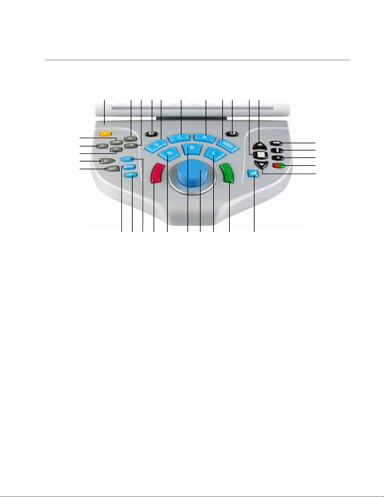
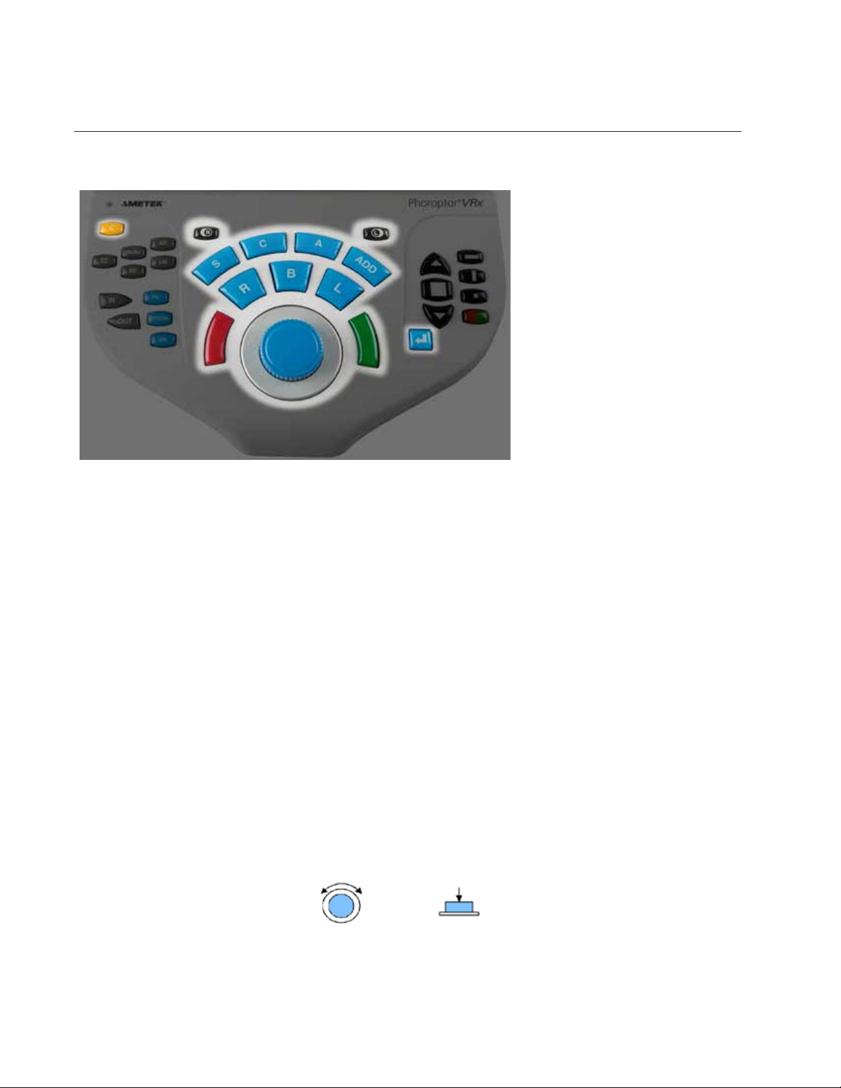
Controller Keypad
31
30
29
28
27
1
26 25 18
Figure IS-33, Controller Keypad
202123 22 1924
10 1198765432
12
13
14
15
16
17
1. C—Clear
2. AR—Auto Refractor
3. LM—Lensmeter
4. R—Right Eye Occluder
5. S—Sphere Adjustment
6. C—Cylinder Adjustment
7. A—Axis Adjustment
8. ADD—Near Vision Addition Adjustment
9. L—Left Eye Occluder
10. Display Multiple Lines of Optotypes
11. Improves Visual Acuity or Increases Optotype Size
12. Horizontal Line
13. Vertical Line
14. Single Optotype
15. Red/Green Filter
16. Decreases Visual Acuity or Decreases Optotype Size
16243-101 Rev. G
17. Enter Key
18. Green button for Split Prism Test
19. L—Open Left Eye, Close Right Eye
20. Control Knob
21. B—Binocular Vision Measurement
22. R—Open Right Eye, Close Left Eye
23. Red button for Split Prism Test
24. PD—Pupillary Distance Measurement
25. BB—Binocular Balance
26. PRISM—Brings in prism lenses
27. OUT—Export Refraction Data
28. IN—Import Pre-test Data
29. SC—Data Without Correction/Plano
30. CC—Data With Correction/Final
31. SUBJ—Subjective Refraction Data
25
Instrument Setup (continued)
Controller Keypad (continued)
Lens Buttons
These buttons control the lenses
and apertures during an exam.
Press the different types of buttons (S, C, A, Add) to activate
different sets of lenses in the
Visutron 900 Touch Head.
C Enters Clear Mode, to enable the clearing of individual data or all of the data.
R Occludes the right eye.
L Occludes the left eye.
S Activates sphere adjustment.
C Activates cylinder adjustment.
A Activates axis adjustment.
ADD Activates the near vision mode.
R Opens the right eye, occludes the left eye.
B Opens both eyes.
L Opens the left eye, occludes the right eye.
Red Either adjusts the current value by a single increment, or indicates patient preference in the Split
Cylinder test.
Green Either adjusts the current value by a single increment, or indicates patient preference in the Split
Cylinder test.
Enter Functionality depends on the current mode or test.
Control Knob
• Turn the Control Knob to adjust the sphere power, cylinder power, axis, or the power of prism.
• Press and turn the Control Knob at the same time to adjust the sphere by 1.00 D increments, to the
cylinder by 1.00 D increments, the prism power by 1.00 D increments, or the axis by 10° increments.
• PresstheControlKnobtomovetothenextrefractionstepornishtheoperation.
Turn Button
-continued-
26 16243-101 Rev. G
Press Button
Instrument Setup (continued)
Controller Keypad (continued)
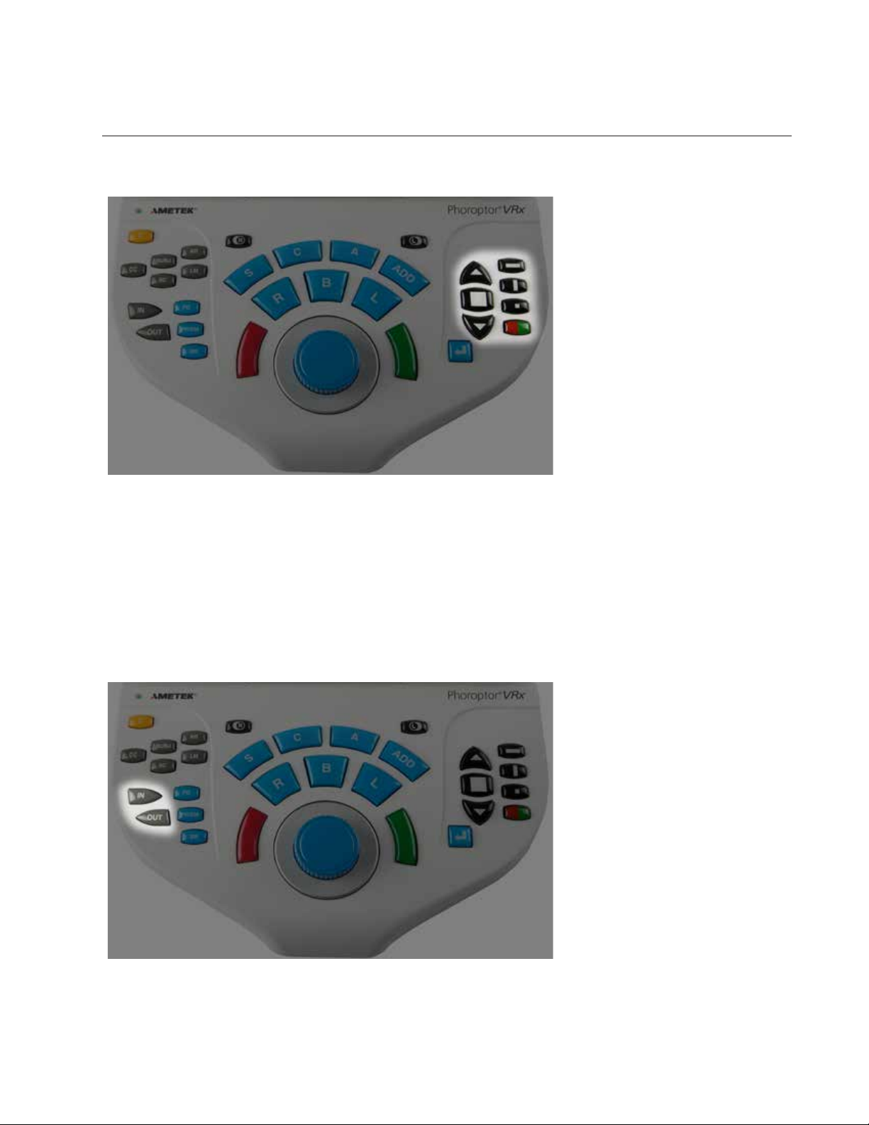
Chart Buttons
These buttons control the
optotype size and layout on the
connected acuity chart.
Up Arrow Improves visual acuity or increases optotype size, depending on the user selected
setting.
Square Displays three lines of optotypes.
Down Arrow Decreases visual acuity or decreases optotype size, depending on the user selected
setting.
Horizontal Line Displays a single horizontal line of optotypes.
Vertical Line Displays a single vertical line of optotypes.
Single Optotype Displays one single optotype.
Red/Green Displaysred/greenlteronselectedoptotype.Eachhalfcontainsidenticaloptotypes.
In & Out Buttons
These buttons access incoming
pre-test data or export outgoing
exam data.
IN Presents pre-test equipment data imported into the Visutron 900 Touch.
OUT SendsdataouttotheEMRsystemorprintsthedata.Thespecicdatasentisselectedinthe
Settings menu.
16243-101 Rev. G
27
 Loading...