

Haag-Streit Biometer LS900 User manual [de]
1
1
© Haag-Streit AG, CH-3098 Koeniz, Switzerland1500.7220055.04030
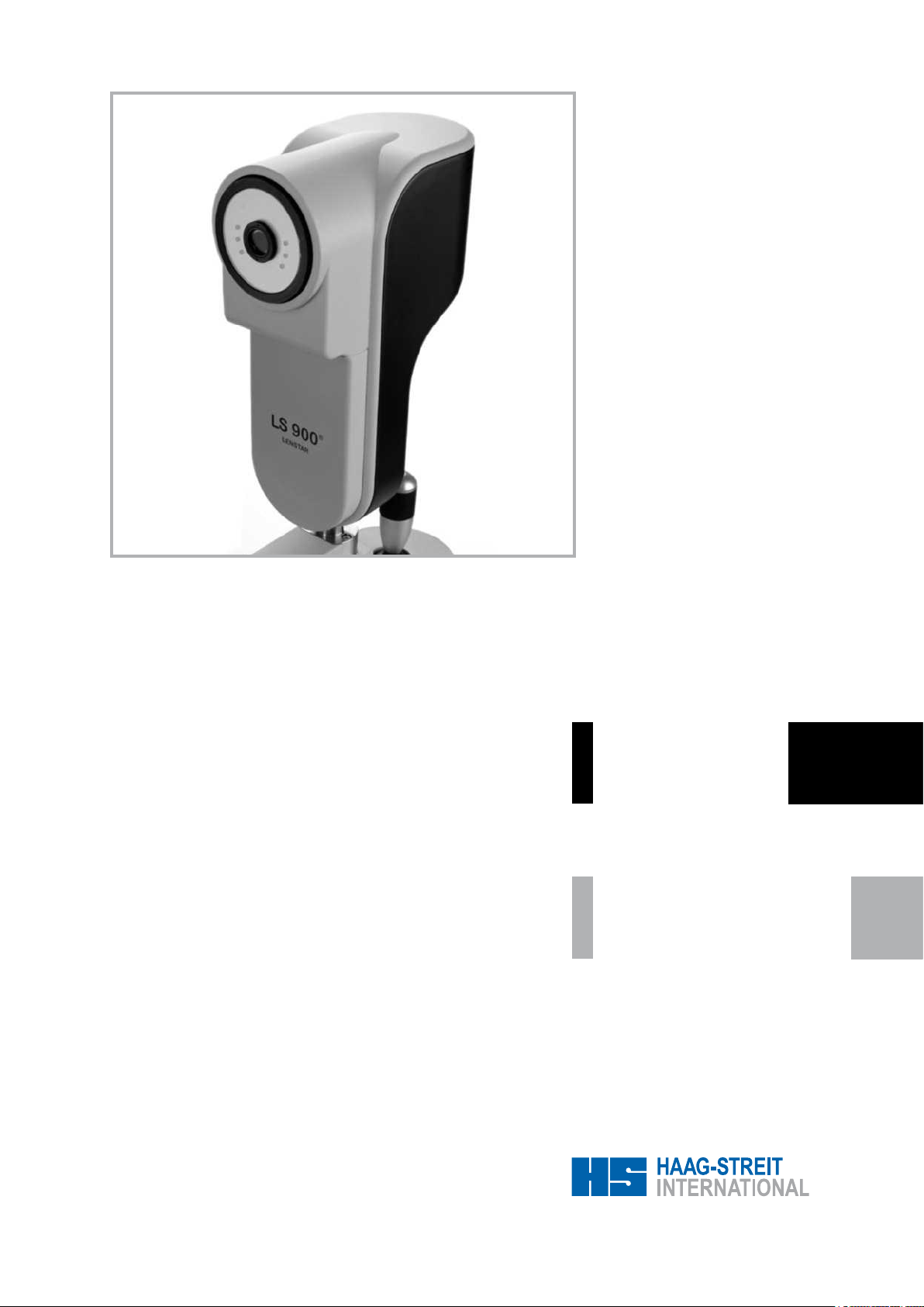
LENSTAR LS 900
®
Biometer
Biomètre
Biometer
Zusätzliche Informationen
Informations supplémentaires
Additional informations
Gebrauchsanweisung
Mode d'emploi
Instruction manual

© Haag-Streit AG, CH-3098 Koeniz, Switzerland 1500.7220055.04030
2
2
Vorwort
Wir danken Ihnen, dass Sie sich für ein Haag-Streit Gerät entschieden haben. Bei sorgfältiger Einhaltung der Vorschriften in dieser Gebrauchsanweisung können wir Ihnen eine zuverlässige und problemlose Anwendung unseres Produktes gewährleisten.
Zweckbestimmung
Der LS 900® ist ein nicht-invasiver, kontaktloser OLCR (optische nied-
rig-Kohärenz Reektometrie) Biometer zum ausmessen verschiedene
Augenparameter zur Berechnung und Bestimmung der für den Pa-
tienten geeigneten Intraokularlinsen (IOL) für die Implantation nach
Entfernung der natürlichen kristallinen Linse. Der LS 900® misst:
Die axiale Länge des Auges • Die Hornhautdicke • Die Tiefe der Vorderkammer • Die Tiefe wässerige • Die Dicke der wässrigen Linse •
Der Radius der Krümmung des Hornhaut Meridian von ach zu steil
• Die Achse des achen Meridians • Weiß-weiß Abstand • Der Pu-
pillendurchmesser.
Inhaltsverzeichnis
1 Sicherheitshinweise
1.1 Allgemeines . . . . . . . . . . . . . . . . . . 4
1.2 Plausibilität der Messungen . . . . . . . . . . 6
1.3
IOL-Berechnung . . . . . . . . . . . . . . . . 8
1.3.1 Referenzen . . . . . . . . . . . . . . . . . . 8
1.4 IOL Konstanten . . . . . . . . . . . . . . . . 8
1.4.1 IOL Konstanten errechnet aus Daten
eines optischen Biometer . . . . . . . . . . . 8
1.4.2 IOL Konstanten errechnet aus Daten
eines immersionsultraschall Biometer . . . . . 8
1.4.3 IOL Konstanten errechnet aus Daten
eines kontaktultraschall Biometer . . . . . . 10
1.5 Elektrische Anschlüsse . . . . . . . . . . . 10
1.6 Optische Strahlung . . . . . . . . . . . . . 10
1.7 Gerät transportieren . . . . . . . . . . . . . 10
1.8 Spezielle Hinweise im Text . . . . . . . . . 10
1.9 Piktogramme . . . . . . . . . . . . . . . . . 12
1.10 Typenschid . . . . . . . . . . . . . . . . . . 12
1.11 Garantie . . . . . . . . . . . . . . . . . . . 12
1.12 Gesetzliche Vorschriften . . . . . . . . . . . 12
2 Einführung
2.1 Grobaufbau . . . . . . . . . . . . . . . . . 14
2.2 Untersuchungsteil (LS 900®) . . . . . . . . . 14
2.3 Steuerteil (PC) . . . . . . . . . . . . . . . . 16
2.3.1 Minimalanforderungen PC . . . . . . . . . . 16
2.3.2 Minimalanforderungen Monitor . . . . . . . 16
2.4 Instrumententisch . . . . . . . . . . . . . . 16
3 Installation
3.1 Sichere Systemkonguration . . . . . . . . 18
3.2 Instrumententisch . . . . . . . . . . . . . . 18
3.2.1 Montage Rollschiene/Gleitplatte . . . . . . . 18
3.2.2 Automatische Positionserkennung . . . . . . 18
3.3 Montage Gerät . . . . . . . . . . . . . . . . 20
3.3.2 Verkabelung . . . . . . . . . . . . . . . . . 20
3.3.3 Seitliche Kabelführung (Option) . . . . . . . 22
3.4 Computer anschliessen . . . . . . . . . . . 22
3.4.1 Software . . . . . . . . . . . . . . . . . . . 22
4 Bedienung
4.1 Messposition des Patienten . . . . . . . . . 24
4.2 Fixation . . . . . . . . . . . . . . . . . . . 24
4.3 Messgrössen. . . . . . . . . . . . . . . . . 24
Avant-propos
Nous vous remercions d’avoir choisi un produit Haag-Streit.
Si les instructions dans le présent mode d’emploi sont strictement
observées, nous pouvons vous assurer que l’utilisation de cet instrument ne vous causera aucun problème.
Objectif d'usage
Le LS 900® est un biomètre OLCR (optique de faible cohérence re-
ectométrique) non-envahissant et sans contact, utilisé pour obtenir
des mesures oculaires et déterminer la puissance et le type de LIO
(lentille intraoculaire) précédant l'implantation après le retrait du cristallin naturel. Le LS 900® mesure :
La longueur axiale de l’œil • Lépaisseur de la cornée • La profondeur de la chambre antérieure • La profondeur aqueuse • L’épaisseur
de la lentille • Le rayon de courbure de la cornée à plat et raide du
méridien • L’axe du méridien plat • L’écart blanc-blanc • Le diamètre de la pupille.
Table des matières
1 Consignes de sécurité
1.1 Généralités. . . . . . . . . . . . . . . . . . . 4
1.2 plausibilité des mesures . . . . . . . . . . . . 6
1.3
Calcul IOL . . . . . . . . . . . . . . . . . . . 8
1.3.1 Références. . . . . . . . . . . . . . . . . . . 8
1,4 constantes IOL . . . . . . . . . . . . . . . . . 8
1.4.1 Constantes IOL calculées à l'aide de mesures
optiques . . . . . . . . . . . . . . . . . . . . 8
1.4.2 Constantes IOL calculées à l'aide de mesures
par immersion à l'ultrason . . . . . . . . . . . 8
1.4.3 Constantes IOL calculées à l'aide de mesures
par contact à l'ultrason . . . . . . . . . . . . 10
1.5 Raccordements électriques . . . . . . . . . 10
1.6 Rayonnement optique . . . . . . . . . . . . 10
1.7 Transport de l’appareil . . . . . . . . . . . . 10
1.8 Informations particulières . . . . . . . . . . 10
1.9 Pictograms . . . . . . . . . . . . . . . . . . 12
1.10 Plaque d’identication . . . . . . . . . . . . 12
1.11 Garantie . . . . . . . . . . . . . . . . . . . 12
1.12 Dispositions légales . . . . . . . . . . . . . 12
2 Introduction
2.1 Structure (grosso modo) . . . . . . . . . . . 14
2.2 La partie examen (LS 900®) . . . . . . . . . 14
2.3 Partie commande (PC) . . . . . . . . . . . 16
2.3.1 Exigences minimales PC . . . . . . . . . . 16
2.3.2 Exigences minimales moniteur . . . . . . . 16
2.4 Table d’instruments . . . . . . . . . . . . . 16
3 Installation
3.1 Conguration de système sûre . . . . . . . 18
3.2 Table d’instruments . . . . . . . . . . . . . 18
3.2.1 Rails de roulement / plaque de glissement . 18
3.2.2 Reconnaissance automatique de la position 18
3.3 Montage partie examen (LS 900®) . . . . . . 20
3.3.2 Câblage . . . . . . . . . . . . . . . . . . . 20
3.3.3 Câble latéral (Option) . . . . . . . . . . . . 22
3.4 Raccordement de l’ordinateur . . . . . . . . 22
3.4.1 Logiciel . . . . . . . . . . . . . . . . . . . . 22
4 Manipulation
4.1 Position de mesure du patient . . . . . . . . 24
4.2 Fixation . . . . . . . . . . . . . . . . . . . 24
4.3 Grandeurs de mesure . . . . . . . . . . . . 24

3
3
© Haag-Streit AG, CH-3098 Koeniz, Switzerland1500.7220055.04030
Introduction
We would like to thank you for your decision to purchase this HaagStreit product.
If the instructions in this manual are carefully followed we are condent
that this product will give you reliable and trouble-free usage.
Purpose of use
The LS 900® is a non-invasive, non-contact OLCR (optical low-coherence reectometry) biometer used for obtaining ocular measurements and performing calculations to assist in the determination of
the appropriate power and type of IOL (intraocular lens) for implantation after removal of the natural crystalline lens. The LS 900®
measures:
Axial eye length • Corneal thickness • Anterior chamber depth • Aque-
ous depth • Lens thickness • Radii of corneal curvature of at and
steep meridian • Axis of the at meridian • White-to-white distance
• Pupil diameter.
Contents
1 Safety instructions
1.1 General Points . . . . . . . . . . . . . . . . . 5
1.2 Plausibility of measurements . . . . . . . . . 7
1.3
IOL calculation . . . . . . . . . . . . . . . . . 9
1.3.1 References. . . . . . . . . . . . . . . . . . . 9
1.4 IOL constants . . . . . . . . . . . . . . . . . 9
1.4.1 IOL constants derived using
optical measurements . . . . . . . . . . . . . 9
1.4.2 IOL constants derived using immersion
ultrasound measurements . . . . . . . . . . . 9
1.4.3 IOL constants derived using contact
ultrasound measurements . . . . . . . . . . 11
1.5 Electrical connections . . . . . . . . . . . . 11
1.6 Optical radiation . . . . . . . . . . . . . . . 11
1.7 Device transportation . . . . . . . . . . . . 11
1.8 Special notes in text . . . . . . . . . . . . . 11
1.9 Pictograms . . . . . . . . . . . . . . . . . . 13
1.10 Device nameplate . . . . . . . . . . . . . . 13
1.11 Warranty and product liability . . . . . . . . 13
1.12 Statutory regulations . . . . . . . . . . . . . 13
2 Introduction
2.1 Basic construction . . . . . . . . . . . . . . 15
2.2 Examination components (LS 900®) . . . 11 / 15
2.3 Control component (PC) . . . . . . . . . . . 17
2.3.1 Minimum PC requirements . . . . . . . . . 17
2.3.1 Minimum monitor requirements . . . . . . . 17
2.4 Instrument table . . . . . . . . . . . . . . . 17
3 Installation
3.1 Safe system conguration . . . . . . . . . . 19
3.2 Instrument table . . . . . . . . . . . . . . . 19
3.2.1 Mounting the roller rails/slide plate . . . . . 19
3.2.2 Automatic position recognition . . . . . . . . 19
3.3 Mounting the device . . . . . . . . . . . . . 21
3.3.2 Wiring cable under the device . . . . . . . . 21
3.3.3 Cables at side (Option) . . . . . . . . . . . 23
3.4 Computer connection . . . . . . . . . . . . 23
3.4.1 Software . . . . . . . . . . . . . . . . . . . 23
4 Operation
4.1 Position of patient during measurement . . . 25
4.2 Fixation . . . . . . . . . . . . . . . . . . . 25
4.3 Measured variables . . . . . . . . . . . . . 25

© Haag-Streit AG, CH-3098 Koeniz, Switzerland 1500.7220055.04030
4
4
1 CONSIGNES DE SÉCURITÉ
1.1 Généralités
• Le présent appareil ne doit être utilisé qu’à des ns décrites dans
cette notice d’utilisation.
• L’installation doit impérativement être effectuée par un spécialiste
qualié.
• L’appareil ne doit pas être stocké ou utilisé dans des environnements autres que ceux prescrits dans la présente notice
(voir chapitre 7.1.5).
• Si l’appareil change d’un environnement froid vers un environnement de service, il se peut que de l’eau de condensation se forme sur
les surfaces froides. Avant d’allumer l’appareil, il convient d’attendre
quelques heures jusqu'à ce que l'appareil soit sec et adapté à la température ambiante.
• Veuillez conserver l'emballage pour pouvoir le réutiliser en cas
d’un éventuel renvoi du matériel ou de déménagement.
• L’appareil est utilisé dans un environnement médical avec une
lumière tamisée.
• Il est recommandé de conserver la notice d’utilisation à un endroit
accessible à tout moment pour toutes les personnes travaillant avec
cet appareil. L’utilisateur ne peut bénécier de la garantie qu’à condition de se conformer aux instructions de la notice d’utilisation.
• Le médecin ou l’opérateur est tenu d’informer le patient des consignes de sécurité le concernant et de veiller à ce que ces consignes
soient respectées.
• Ne pas utiliser l’appareil dans des zones présentant un risque
d’explosion, ne pas conserver de solvants volatiles (alcools, es-
sence, etc.) et des produits anesthésiques inammables à proximité
de l’appareil.
• Avant d’allumer l’appareil, il faut toujours retirer la housse de protection. Les sources lumineuses risqueraient d’être détruites en raison d’une surchauffe. Assurez-vous par ailleurs que l’appareil a bien
été éteint avant de le recouvrir.
• Seul un personnel sufsamment qualié et autorisé est habilité
à retirer des éléments du boîtier et à effectuer des réparations. Des
réparations inappropriées peuvent entraîner des risques importants
pour les opérateurs et les patients.
• Pour effectuer des réparations, seuls des pièces d’origine et des
accessoires d’origine doivent être utilisés.
• Ce type d'appareil de mesure fragile nécessite une vérication chaque fois qu’il a été exposé à un impact extérieur (p.ex. des chocs ou
chutes involontaires) conformément au chapitre 6.1 (vérication du
bon fonctionnement), et, le cas échéant, il convient de le renvoyer à
l’usine pour réparation.
• Le fabricant de l’appareil n’est pas responsable d’une perte ou
d’un endommagement survenu/e en cas d’utilisation non autorisée.
Dans de tels cas, toute revendication de garantie devient caduque.
• L’examen des patients, l’opération de l’appareil et l’interprétation
des résultats sont des actes réservés aux personnes sufsamment
qualiées et expérimentées (génération des données de mesure et
calculs, avec entrée manuelle, édition et suppression des données).
Tous les utilisateurs doivent-être convenablement formés et familiarisés avec le contenu du manuel d'utilisation, avec une référence
particulière aux consignes de sécurité qu'il contient.
1 SICHERHEITSHINWEISE
1.1 Allgemeines
• Das vorliegende Gerät darf nur zu dem in dieser Gebrauchsanweisung beschriebenen Zweck verwendet werden.
• Installation nur durch geschultes Fachpersonal
• Das Gerät darf nicht ausserhalb der vorgeschriebenen Umgebungsbedingungen (siehe Kapitel 7.1.5) gelagert oder betrieben
werden.
•
Wird das Gerät aus kalter Umgebung in Betriebsumgebung gebracht, kann sich an kalten Oberächen Kondenswasser bilden. Warten Sie vor dem Einschalten des Gerätes ein paar Stunden, bis das
Gerät an die Umgebungstemperatur angeglichen und trocken ist.
•
Bitte Verpackungsmaterial sorgfältig aufbewahren, damit es bei
einer allfälligen Rücksendung oder einem Umzug wieder verwendet
werden kann.
• Das Gerät wird in einem Raum im medizinischen Bereich mit gedämpftem Licht eingesetzt.
• Bewahren Sie diese Gebrauchsanweisung an einem Ort auf, wo
sie für Personen, welche mit dem Gerät arbeiten, jederzeit zugänglich
ist. Garantieansprüche können nur geltend gemacht werden, wenn
die Weisungen in der Gebrauchsanweisung beachtet werden.
• Der Arzt bzw. die Bedienungsperson ist verpichtet, dem Patienten
die ihn betreffenden Sicherheitshinweise zu unterbreiten und deren
Befolgung zu überwachen.
• Gerät nicht in explosionsgefährdeten Bereichen benutzen, keine
üchtigen Lösungsmittel (Alkohol, Benzin usw.) und brennbaren Narkosemittel in der Nähe aufbewahren.
• Vor dem Einschalten des Gerätes ist die Überwurfhülle immer zu
entfernen. Die Lichtquellen können sonst durch Überhitzung zerstört
werden. Vergewissern Sie sich anderseits, dass das Gerät vor dem
Zudecken ausgeschaltet wird.
• Entfernen von Gehäuseteilen und Reparaturen dürfen nur von entsprechend ausgebildetem und autorisiertem Fachpersonal durchgeführt werden. Durch unsachgemässe Reparaturen können erhebliche
Gefahren für Bedienungspersonen und Patienten entstehen.
• Für Reparaturen dürfen nur Original-Ersatzteile und Original-Zubehör verwendet werden.
• Dieser Typ eines empndlichen Messgeräts muss nach jeder äusserlichen Krafteinwirkung (z.B. ungewollte Erschütterung oder fallen
lassen) gemäss Kapitel 6.1 (Funktionsüberprüfung) überprüft, und
wenn nötig zur Reparatur ins Werk zurückgeschickt werden.
• Der Hersteller des Gerätes ist nicht haftbar für Verlust oder Beschädigung aufgrund unautorisierter Behandlung desselben. Sämtliche daraus entstehenden Garantieansprüche verfallen.
• Die Untersuchung der Patienten, die Bedienung des Gerätes und
die Interpretation der Ergebnisse darf nur von ausgebildeten und
erfahrenen Personen (welche das Erzeugen von Messdaten und
Berechnungen, sowie die manuelle Erfassung, Bearbeitung und Lö-
schung von Daten beherrschen) durchgeführt werden. Alle Benutzer
müssen entsprechend ausgebildet und mit dem Inhalt der Betriebsanleitung vertraut sein, insbesondere in Bezug auf die enthaltenen
Sicherheitsanweisungen.
• Messungen können mit erweiterten oder normale Pupillen durchgeführt werden. Der A-Scan (axiale Augen Länge, die Hornhautdicke,
4.3.1 A-Scan . . . . . . . . . . . . . . . . . . . . 24
4.3.2
Keratometrie . . . . . . . . . . . . . . . . . 24
4.3.3 Weiss-Weiss Abstand . . . . . . . . . . . . 26
4.3.4 Pupillometrie & Sehachse . . . . . . . . . . 26
5
Bedienungsanleitung Software . . 26
6
PegeundUnterhalt . . . . . . . . . 26
6.1 Funktionsüberprüfung . . . . . . . . . . . . 26
6.1 Reinigung . . . . . . . . . . . . . . . . . . 28
7 Anhang
. . . . . . . . . . . . . . . . . . 28
4.3.1 A-Scan . . . . . . . . . . . . . . . . . . . . 24
4.3.2
Kératométrie . . . . . . . . . . . . . . . . . 24
4.3.3 Ecart blanc-blanc . . . . . . . . . . . . . . 26
4.3.4 Pupillométrie & axe visuel . . . . . . . . . . 26
5
Mode d'emploi du logiciel . . . . . . . . . 26
6
Entretien et maintenance . . . . . . . . . . 26
6.1 Vérication du bon fonctionnement . . . . . 26
6.2 Nettoyage . . . . . . . . . . . . . . . . . . 28
7 Annexe . . . . . . . . . . . . . . . . . . . . . . 28

5
5
© Haag-Streit AG, CH-3098 Koeniz, Switzerland1500.7220055.04030
1 SAFETY INSTRUCTIONS
1.1 General Points
• The appliance must only be used for the purpose described in this
operating manual.
• Installation should only be carried out by trained technical personnel.
• The device must not be stored or operated outside the prescribed
ambient conditions (see section 7.1.5)
• If the device is brought from a cold environment into the operating environment, condensation may form on cold surfaces. Wait a
couple of hours until the device temperature has equalized and it is
dry, before switching the device on.
• Please carefully retain packing material for reuse in case of return
delivery or removal to another location.
• Please keep this manual near the appliance at all times, in a place
where it can be accessed easily by operating staff. Warranty claims
will only be considered if the instructions in the operating manual
have been followed as specied.
• The doctor or operator undertakes to give the patient those safety instructions that concern him/her, and to monitor for their compliance.
• Do not use the device in areas where there is a risk of explosion.
Do not store volatile solvents (alcohol, petrol, etc.) or ammable narcotics in the vicinity.
• Always remove the dust cover before switching on the device.
Otherwise, the light sources may be destroyed by overheating. After
use, ensure that the device is switched off before replacing the cover.
• The removal of housing parts and repairs should only be undertaken by appropriately trained and authorized specialist staff. Improper
repairs may result in considerable risk to operator and patient.
• Only original spare parts and accessories may be used for repairs.
• If exposed to the effects of an external force (e.g. by being acci-
dentally knocked or dropped), this type of sensitive measuring device
must be promptly checked according to section 6.1 (Function check)
and, if necessary, returned to the factory for repair.
• The manufacturer of this device is not liable for loss or damage
due to its unauthorized handling. All consequent guarantee claims
become invalid.
• Only suitably-trained and experienced staff must operate the software (for the generation of measuring data and calculations, along with
the manual entry, editing and deletion of data) and interpret results.
All members of operating staff must be suitably-trained and familiar
with the contents of the operating manual, with particular reference
to the safety instructions contained in it.
• Measurements can be carried out with dilated or undilated pupils. The A-scan (axial eye length, corneal thickness, anterior cham-
ber depth, lens thickness), keratometry and white-to-white distance
measurement are not inuenced by dilatation status. Dilatation status
does have a bearing on pupillometry.
• The software must only be installed by persons trained to do so.
• The PC on which the EyeSuite Biometry software is installed must
not contain or run any other software that might limit the functioning
4.3.1 A-Scan . . . . . . . . . . . . . . . . . . . . 21
4.3.2
Keratometry . . . . . . . . . . . . . . . . . 21
4.3.3 White-to-white distance . . . . . . . . . . . 23
4.3.4 Pupillometry and visual axis . . . . . . . . . 23
5
Software guide . . . . . . . . . . . . . . . . . 23
6
Care and maintenance . . . . . . . . . . . 23
6.1 Function check . . . . . . . . . . . . . . . . 23
6.2 Cleaning . . . . . . . . . . . . . . . . . . . 25
7 Appendix
. . . . . . . . . . . . . . . . . . . . 25

© Haag-Streit AG, CH-3098 Koeniz, Switzerland 1500.7220055.04030
6
6
• Les mesures peuvent être réalisées avec des pupilles dilatées ou
non dilatées. L'A-scan (longueur axiale oeil, l'épaisseur de la cornée,
la profondeur de la chambre antérieure, épaisseur de la lentille), la
kératométrie et l’écart blanc-blanc n’en sont pas inuencés. L'état de
dilatation a une incidence sur la pupillométrie.
• Le logiciel doit être installé par des personnes formées.
• Le PC sur lequel le logiciel EyeSuite biométrie est installé ne doit
pas contenir ou exécuter nul autre logiciel qui pourrait limiter la capacités de fonctionnement d'Eyesuite.
•
Effectuer la vérication du bon fonctionnement lorsque le logiciel
vous y invite (propriétés de mesure, reconnaissance du côté).
• Etteignez l'ordinateur en cas de non-usage prolongué du
système.
1.2 plausibilité des mesures
• L’utilisateur doit vérier la plausibilité des résultats de mesure.
Ceci implique de vérier l'A-scan et le curseur, qui est automatiquement ajusté par rapport au signal, chaque fois que le LS 900® af-
che un écart anormalement élevé pour la longueur axiale des yeux,
l’épaisseur de la cornée, la profondeur de la chambre antérieure et
/ ou l’épaisseur de la lentille. L’utilisateur doit également prendre en
compte le type (par ex. la cataracte sous-capsulaire postérieure) et
la densité de la cataracte au moment d'en évaluer la plausibilité.
• Il est possible que les résultats de mesure de patients dont la
cornée n’est pas intacte (p.ex. greffe de cornée, cornée trouble, ci-
catrices cornéennes) soient imprécis (cela vaut notamment pour la
kératométrie), l’utilisateur doit donc vérier s’ils sont plausibles.
• Nous recommandons la réalisation d'au moins cinq mesures pour
chaque œil.
• Avant d’effectuer la mesure, l’utilisateur doit vérier que le patient
ne porte pas de lentilles de contact. La présence de lentilles de contact fausse les résultats de mesure.
• Sous de certaines conditions, il ne peut pas être possible d'effectuer
des mesures sur des personnes ayant des problèmes de xation.
• Des opacités lenticulaires denses peuvent rendre impossible de
mesurer la longueur axiale de l'oeil et de l'épaisseur de la lentille.
• Des opacités prononcées de la cornée centrale peuvent également
rendre impossible de mesurer l'épaisseur cornéenne, la profondeur
de la chambre antérieure, l'épaisseur de la lentille ou la longueur axiale de l'oeil.
• La présence de sang dans le corps vitré peut rendre impossible
de mesurer la longueur axiale de l'oeil.
• La kératométrie peut ètre erronée si l'oeil a subi une opération
keratorefractive prèalablement, car il peut presenter des écarts de
surfaces sphériques considérables.
• L’utilisateur doit vérier visuellement au moment de la mesure si
tous les points lumineux sont présents.
• Si des messages d’erreur s’afchent à répétition, il convient de ne
pas utiliser l’appareil et d’appeler le service après-vente.
• Il est recommandé de toujours mesurer les deux yeux du patient.
En cas de divergences importantes entre l’œil droit et l’œil gauche,
l'utilisateur doit procéder à une vérication particulièrement attentive
des résultats de mesure. On entend par divergences importantes :
- plus d’1 dpt concernant la force de réfraction centrale de la cornée
=> une différence de 0,18 mm du rayon de courbure de la
cornée
- plus de 0,3 mm de la longueur axiale
- plus d’1 dpt concernant la force de réfraction emmétropique
de la LIO (lentille intraoculaire)
• L'utilisateur doit vérier l'A-scan lorsqu'il s'agit de mesurer la pro-
fondeur de la chambre antérieure en mode pseudophaque. Si un
seul signal IOL est visible, il n'est pas clair si ce signal se rapporte à
l'avant ou l'arrière de la IOL. L'incertitude dans ce cas peut conduire
à la lecture de valeurs inexactes pour la profondeur de la chambre
antérieure dues par l'épaisseur de la IOL (environ + / -1 mm).
• Une IOL trop inclinée ou décentrée peut rendre impossible de
mesurer la profondeur de la chambre antérieure et la profondeur
die Tiefe der vorderen Augenkammer, Linsen- Dicke), Keratometrie
und Weiss-Weiss Abstand werden durch die Erweiterung nicht beeinusst. Der Zustand der Erweiterung wirkt sich jedoch auf die Pupillometrie aus.
•
Die Software muss von geschulten Personen installiert werden.
• Der PC, auf dem die EyeSuite Biometrie Software installiert ist darf
keine andere Software enthalten welche das korrekte Funktionieren
von EyeSuite einschränken könnten.
• Funktionskontrolle nach Aufforderung der Software durchführen
(Messeigenschaften, Seitenerkennung)
• Bei längerem Nichtgebrauch des Systems, Computer bitte ausschalten
1.2 Plausibilität der Messungen
• Die Messergebnisse sollen vom Benutzer auf Plausibilität geprüft
werden. Dazu gehört die Überprüfung des A-Scans und der Cursor,
der automatisch in Bezug zum Signal angepasst wird, , wenn der LS
900® eine außergewöhnlich hohe Standardabweichung für axiale
Augenlänge, Hornhautdicke, Tiefe der vorderen Augenkammer und
/ oder Linsendicke zeigt. Der Benutzer sollte bei der Bewertung der
Plausibilität, die Art und die Dichte der Katarakt berücksichtigen. (z.
B. hinteren subkapsulären Katarakts)
• Messresultate von Patienten mit nicht intakter Kornea (z.B. Horn-
hauttransplantat, Hornhauttrübung, Hornhautnarben) sind möglicherweise ungenau (insbesondere gilt dies für die Keratometrie) und
müssen vom Benutzer auf Plausibilität geprüft werden.
• Wir empfehlen die Durchführung von fünf Messungen pro Auge.
• Vor der Messung muss sich der Benutzer vergewissern, dass der
Patient keine Kontaktlinsen trägt. Das Vorhandensein von Kontaktlinsen verfälscht die Messresultate.
• Unter gewissen Umständen ist es nicht möglich Messungen an
Personen mit Fixierungs-Probleme durchzuführen.
• Dichte Linsentrübungen können es unmöglich machen, die axiale
Augenlänge und die Linsendicke zu messen.
• Starke Trübungen der zentralen Hornhaut können ebenfalls die
Messungen von Hornhautdicke, Vorderkammertiefe, Linsendicke
oder axiale Augenlänge unmöglich machen.
• Blut im Glaskörper kann die Messungen der axialen Augenlänge
unmöglich machen.
• Die Keratometrie kann falsche Werte bei Augen welche einer keratorefractiven Operation unterzogen wurden liefern, da solche Augen erhebliche abweichungen der sphärischen Fläche aufweisen
können
• Der Benutzer soll bei der Messung visuell prüfen, ob alle Lichtpunkte vorhanden sind.
• Bei sich wiederholenden Fehlermeldungen Gerät nicht weiterverwenden und den Kundendienst benachrichtigen.
• Es wird empfohlen, immer beide Augen eines Patienten zu messen. Bei grossen Unterschieden zwischen dem rechten und linken
Auge müssen die Messergebnisse vom Benutzer einer besonderen
Betrachtung unterzogen werden. Grosse Unterschiede sind:
- mehr als 1 dpt bei der zentralen Hornhautbrechkraft
=> 0,18 mm Unterschied beim Hornhautkrümmungsradius
- mehr als 0,3 mm bei der Achslänge
- mehr als 1 dpt bei der emmetropischen IOL-Brechkraft
• Der Benutzer sollte die A-Scan bei der Messung der Vorderkammertiefe im pseudophaken-Modus überprüfen. Wenn nur ein IOL
Signal sichtbar ist, ist es nicht klar, ob dieses Signal sich auf der
Vorder-oder Rückseite der IOL bezieht. Unsicherheit in diesem Fall
kann dazu führen, dass die angezeigten Werte für Vorderkammer-
tiefe durch die Dicke der IOL (ca. + / -1 mm) ungenau ausfallen.
• Eine zu geneigte oder dezentrierte IOL kann es verunmöglichen,
die Tiefe der vorderen Augenkammer und die Tiefe des Glaskörpers
in pseudophaken Augen zu messen.
• Eine korrigierte Augeninnendruck-Messung auf Grundlage der
gemessenen Hornhautdicke stellt keine zuverlässige Diagnose des
Glaukoms dar.

7
7
© Haag-Streit AG, CH-3098 Koeniz, Switzerland1500.7220055.04030
capabilities of EyeSuite.
• Please keep this manual near the appliance at all times, in a place
where it can be accessed easily by operating staff. Warranty claims
will only be considered if the instructions in the operating manual
have been followed as specied.
• Execute function checks when prompted by software (measure-
ment properties, side recognition)
• Shut down the computer whenever the system is to be out of use
for an extended period.
1.2 Plausibility of measurements
• Users should check measurement readings for plausibility. This
involves verifying the A-scan and the cursor, which is automatically
adjusted with respect to signal peaks, whenever the LS 900
®
displays
an abnormally-high standard deviation for axial eye length, corneal
thickness, anterior chamber depth and/or lens thickness. The operator should also take into account the type (e.g. posterior subcapsular
cataract) and density of the cataract when evaluating plausibility.
•
Measurement readings obtained from patients with a non-intact
cornea (e.g. due to a corneal transplant, corneal opacity or corneal
scarring) may possibly be inaccurate (this applies to keratometry in
particular), and the user should check the data for plausibility.
• We recommended the carrying-out of ve measurements on each
eye.
•
The user should ensure, before carrying out the measurement
procedure, that the patient is not wearing contact lenses, as their
presence is likely to give rise to incorrect measurement readings.
•
It may not be possible, under certain circumstances, to carry out
measurements on persons with xation problems.
• Dense lenticular opacities may make it impossible to measure the
axial eye length and lens thickness.
•
Pronounced opacities of the central cornea can likewise make it
impossible to measure corneal thickness, anterior chamber depth,
lens thickness or axial eye length.
•
Blood in the vitreous may make it impossible to measure the axial
eye length.
•
Keratometry may be erroneous in eyes that underwent keratore-
fractive surgery because such eyes may signicantly deviate from
spherical surfaces.
•
The user should make a visual check, when carrying out the
measurement procedure, to ensure that all light spots are present.
•
If the appliance repeatedly generates error messages, stop using
it and contact customer service.
• You are recommended always to examine both the patient’s eyes.
The user should subject the measurement readings to extra scrutiny
if there is a notable difference between the right and left eye. The
following are classed as notable differences:
-
More than 1 dpt with respect to central corneal refractive pow er -> 0.18 mm difference with respect to the corneal curvature
radius
- More than 0.3 mm with respect to axial eye length
- More than 1 dpt with respect to emmetropic IOL refractive po-
wer
• The user should check the A-scan when measuring anterior chamber depth in pseudophakic mode. If only one IOL signal is visible, it
is not clear whether this signal relates to the front or back of the IOL.
Uncertainty in this case can lead to the displayed reading for anterior
chamber depth being inaccurate by the thickness of the IOL (approx.
+/-1 mm).
•
An excessively tilted or decentered IOL may make it impossible
to measure the anterior chamber depth and aqueous depth in pseudophakic eyes.
•
An intraocular pressure reading corrected on the basis of the
measured corneal thickness does not in itself constitute a reliable
diagnosis of glaucoma.
•
Ambient light has a bearing on pupil-diameter measurement readings. The user is responsible for ensuring the correct level of ambi-

© Haag-Streit AG, CH-3098 Koeniz, Switzerland 1500.7220055.04030
8
8
aqueuse dans les yeux pseudophaques.
• Une lecture de la pression intra-oculaire corrigée sur base de
l'épaisseur cornéenne mesurée ne constitue pas en soi un diagnostic
able de glaucome.
•
La lumière ambiante a une incidence sur les relevés de mesure
du diamètre pupillaire. L'utilisateur est responsable d'assurer le bon
niveau de lumière ambiante lors de l'exécution pupillométrie. La LS
900® ne peut pas contrôler la lumière ambiante, donc n'utilisez pas
la pupillométrie comme facteur décisif en considèrant la chirurgie
keratorefractive.
•
L’écart blanc-blanc indiqué est simplement une mesure indirecte
de la dimension intérieure latérale de la section oculaire antérieure.
Elle prévoit donc que des indications approximatives de la dimension réelle intérieure latérale de la section oculaire antérieure et de la
taille de l'implant utilisé.
1
.3 Calcul IOL
Les mesures prises avec le LS 900® sont un élément central de tous
les calculs IOL. L'autre partie importante est la IOL constante utilisée
pour calculer la puissance d'une IOL à implanter. En utilisant LENSTAR, un biomètre optique sans contact, des constantes optimisées
pour la biométrie optique sont nécessaires. S'il vous plaît contactez le
fabricant IOL pour obtenir des informations sur des constantes optimisées pour l’ensemble individuel de lentilles. Une source alternative
pour les constantes optiques optimisées pour IOL est le site internet
du groupe d'utilisateurs “User Group for Laser Interference Biometry”
(ULIB) de l'Université de Wuerzburg, en Allemagne. Les constantes
qui y sont publiés ont été optimisés pour autres biomètres optiques
que le LS 900®, des études récemment publiées [1, 2, 3] indiquent
que les données ULIB publiés peuvent être utilisés pour calculer la
puissance IOL en relation avec le LS 900®.
Pour améliorer encore le résultat du calcul IOL, il est recommandé
que chaque chirurgien crée des constantes IOL personnalisés basés sur des données pré-opératoires générés avec le LS 900® et
des données à partir d'une analyse de la réfraction stable au moins
3 mois post-opératoire
1.3.1 Références
[1] P J Buckhurst, J S Wolffsohn, S Shah, S A Naroo, L N Davies,
E J Berrow, “A new optical low coherence reectometry device for
ocular biometry in cataract patients”, British Journal of Ophthalmology 2009;93:949-953
[2] M P Holzer, M Mamusa, G U Auffarth, „Accuracy of a new partial coherence interferometry analyser for biométrie measurements”,
British Journal of Ophthalmology 2009;93: 807-810
[3] K Rohrer, B E Frueh, R Wälti, I A Clemetson, C Tappeiner, D
Goldblum, “Comparison and Evaluation of Ocular Biometry Using a
New Noncontact Optical Low-Coherence Reectometer”, accepted
for publication in Ophthalmology
1.4 Constantes IOL
Il est recommandé d'utiliser des constantes IOL personnalisées pour
obtenir une précision maximale de prédiction du calcul IOL. Utilisation des constantes IOL personnalisées minimisent les effets de différentes techniques chirurgicales, de mesures individuelles, du matériel
de chirurgie, de la dimension oculaires et des spécialités ethniques
d'une population de patients sur le calcul IOL.
1.4.1 Constantes IOL calculées à l'aide de mesures optiques
S'il-y-à des des constantes IOL optimisées ou même personnalisées disponible à partir d'un appareil biométrique optique différente
du LS 900®, ils peuvent être utilisées avec le LS 900® pour obtenir
des résultats cliniquement identiques [1,2,3]. Des constantes optimisées pour biomètres optiques peut également être consultées sur
le site internet du groupe d'utilisateurs ULIB de l'Université de Wuerzburg, en Allemagne.
• Die Raumbeleuchtung hat einen Einuss auf die Messwerte von
Pupillen-Durchmesser. Der Benutzer ist bei der Durchführung der
Pupillometrie für die Gewährleistung des richtigen Umgebungslichts
verantwortlich. Der LS 900® kann das Umgebungslicht nicht überwachen, setzen Sie also nicht die Pupillometrie als entscheidender
Faktor bei der Prüfung für keratorefractive Chirurgie.
•
Der Weiss-Weiss Abstand Wert ist nur eine indirekte Messung der
inneren lateralen Abmessungen des vorderen Augenasbschnitts. Er
bietet deshalb nur ungefähre Angaben über die tatsächlichen inneren lateralen Abmessungen des vorderen Augenasbschnitts und der
Grösse der verwendeten Implantate.
1.3 IOL Berechnung
Die mit dem LENSTAR LS 900 gemachten Messungen sind ein zentrales Element jeder IOL Berechnung. Ein weiterer wichtiger Parameter bei der Berechnung der zu implantierenden Linse ist die IOL
Konstante. Mit dem LENSTAR LS 900 sollten nur IOL Konstanten
verwendet werden, die für optische Biometer optimiert wurden. Bitte kontaktieren sie Ihren Linsenlieferanten um Angaben zu für die
optische Biometrie optimierte IOL Konstanten zu erhalten. Eine alternative Informationsquelle ist die Homepage der „User Group for
Laser Interference Biometry“ (ULIB) der Universität Würzburg. Auch
wenn die dort publizierten Daten für ein anderes optisches Biometer
optimiert wurden, lassen die neusten publizierten Daten [1, 2, 3] den
Schluss zu, dass diese IOL Konstanten auch mit dem LENSTAR zur
Berechnung von IOLs verwendet werden können.
Um das klinische Resultat weiter zu verbessern, empehlt Haag-
Streit dass jeder Benutzer, basierend auf präoperativen Messdaten
von LENSTAR und stabilen postoperativen Daten (zum Beispiel 3
Monate nach der Operation), seine persönlichen optimierten IOL
Konstanten errechnet.
1
.3.1 Referenzen
[1] P J Buckhurst, J S Wolffsohn, S Shah, S A Naroo, L N Davies,
E J Berrow, “A new optical low coherence reectometry device for
ocular biometry in cataract patients”, British Journal of Ophthalmology 2009;93:949-953
[2] M P Holzer, M Mamusa, G U Auffarth, „Accuracy of a new partial coherence interferometry analyser for biométrie measurements”,
British Journal of Ophthalmology 2009;93: 807-810
[3] K Rohrer, B E Frueh, R Wälti, I A Clemetson, C Tappeiner, D
Goldblum, “Comparison and Evaluation of Ocular Biometry Using a
New Noncontact Optical Low-Coherence Reectometer”, accepted
for publication in Ophthalmology
1.4 IOL Konstanten
Es wird empfohlen nur mit personalisierten IOL Konstanten zu arbeiten, um die maximale Vorhersagegenauigkeit zu erhalten. Durch die
Verwendung personalisierter IOL Konstanten werden die Effekte der
individuellen chirurgischen Technik, des verwendeten Messe- und Operationsequipments sowie individuelle physiologische Unterschiede der
operierten Patientenkohorte auf die IOL Berechnung minimiert.
1.4.1 IOL Konstanten errechnet aus Daten eines
optischen Biometer
Sind optimierte oder personalisierte IOL Konstanten eines anderen
optischen Biometer vorhanden, können diese auch mit dem LENSTAR verwendet werden [1, 2, 3]. Optimierte IOL Konstanten für
optische Biometer können auch auf der Homepage der „User Group
for Laser Interference Biometry“ (ULIB) der Universität Würzburg
gefunden werden.
1.4.2 IOL Konstanten errechnet aus Daten eines
immersionsultraschall Biometer
Sind optimierte IOL Konstanten basierend auf Daten eine immersionsultraschall Biometer vorhanden, können diese für die IOL Berechnung mit dem LENSTAR als Startpunkt für eine weitere Optimierung

9
9
© Haag-Streit AG, CH-3098 Koeniz, Switzerland1500.7220055.04030
ent light when carrying out pupillometry. The LS 900® cannot monitor
ambient light, so do not use pupillometry as the decisive factor when
considering keratorefractive surgery.
• The white-to-white distance reading is merely an indirect measurement of the inner lateral dimensions of the anterior ocular section. It
therefore provides only approximate indications of the actual inner
lateral dimensions of the anterior ocular section and of the size of
the implant used.
1.3 IOL calculation
The measurements taken with the LS 900® are one central element
of every IOL calculation. The other important part is the IOL constant
used to calculate the power of an IOL to be implanted. Using the LS
900
®
, an optical non contact biometer, constants optimised for optical
biometry should be used. Please contact the respective IOL Manufacturer to get information on optimised IOL constants for an individual
set of lenses used. An alternative source for IOL constants optimised
for optical biometry is the homepage of the “User Group for Laser In-
terference biometry” (ULIB) of the University of Wuerzburg, Germany.
Even tough the constants published there have been optimised for a
different optical biometer than the LS 900®, recently published, peer
reviewed studies [1, 2, 3] indicate that ULIB published data can be
used to calculate IOL power in connection with the LS 900®.
To further improve the outcome of the IOL calculation, it is recommended that every surgeon creates personalised IOL constants based on
pre-operative data generated with the LS 900® and data from a stable
refraction analysis at least 3 month post-operative.
1.3.1 References
[1] P J Buckhurst, J S Wolffsohn, S Shah, S A Naroo, L N Davies,
E J Berrow, “A new optical low coherence reectometry device for
ocular biometry in cataract patients”, British Journal of Ophthalmology 2009;93:949-953
[2] M P Holzer, M Mamusa, G U Auffarth, „Accuracy of a new partial coherence interferometry analyser for biometry measurements”,
British Journal of Ophthalmology 2009;93: 807-810
[3] K Rohrer, B E Frueh, R Wälti, I A Clemetson, C Tappeiner, D
Goldblum, “Comparison and Evaluation of Ocular Biometry Using a
New Noncontact Optical Low-Coherence Reectometer”, accepted
for publication in Ophthalmology
1.4 IOL constants
It is recommended to use personalised IOL constants to achieve
maximum prediction accuracy of the IOL calculation. Using personalised IOL constants minimises the effects of individual surgical
techniques, individual measurement- and surgical-equipment, ocular dimensions and ethnic specialities of a patient population on the
IOL calculation.
1.4.1 IOL constants derived using optical measurements
If there are optimised or even personalised IOL constants available
from a different optical biometer than the LS 900®, they may be used
as well with the LS 900® to achieve clinically identical results [1,2,3].
Optimised constants for optical biometers can also be found on the
web site of the “User Group for Laser Interference Biometry” (ULIB)
of the University of Wuerzburg, Germany.
1.4.2 IOL constants derived using immersion ultrasound
measurements
If there are optimised IOL constants available for immersion ultrasound, they may be used as a starting point for IOL calculation with
the LS 900®. Still differences in IOL calculation may occur due to differences in the keratometry measurements of the LS 900® and the
keratometer used in combination with the immersion ultrasound. A
comprehensive manual how to convert existing ultrasound biometry
optimised IOL constants to optical biometry optimised IOL constants
can be found on the web site of the “User Group for Laser Inter-

© Haag-Streit AG, CH-3098 Koeniz, Switzerland 1500.7220055.04030
10
10
1.4.2 Constantes IOL calculées à l'aide de mesures par
immersion à l'ultrason
S'il-y-à des des constantes IOL optimisées pour les ultrasons en immersion, elles peuvent être utilisées comme point de départ pour le
Calcul IOL avec le LS 900®. Des différences dans le calcul IOL peuvent se produire en raison des différences dans les mesures de la
kératométrie du LS 900® et du kératomètre utilisé en combinaison
avec l'échographie en immersion. Un manuel complet de comment
convertir les données existantes de constantes IOL optimisées pour
la biométrie ultrasonore à celles des constantes IOL optimisées àla
biométrie optique s peuvent être trouvées sur le site internet du groupe d'utilisateurs ULIB de l'Université de Wuerzburg, en Allemagne.
Les valeurs converties doivent être utilisées comme point de départ
pour calculer les constantes IOL personnalisés
1.4.3 Constantes IOL calculées à l'aide de mesures par
contact à l'ultrason
S'il-y-a des constantes disponibles optimisé pour un biomètre à contact par ultrasons en combinaison avec un kératomètre, les constantes IOL respectives des doivent être converties en constantes optimisées pour la biométrie optique. Un manuel complet de comment
convertir les données existantes de constantes IOL optimisées pour
la biométrie ultrasonore à celles des constantes IOL optimisées àla
biométrie optique s peuvent être trouvées sur le site internet du groupe d'utilisateurs ULIB de l'Université de Wuerzburg, en Allemagne.
Les valeurs converties doivent être utilisées comme point de départ
pour calculer les constantes IOL personnalisés.
1.5 Raccordements électriques
• Utiliser exclusivement une alimentation secteur externe, autorisée
par Haag-Streit et adaptée aux appareils médicaux (IEC/EN60601-1,
UL60601-1, CAN/CSA C22.2 N° 601.1-M90).
• Le connecteur, le câble et la borne de mise à la terre de la prise
doivent être en parfait état de fonctionnement.
• Assurez-vous que l’appareil n’est raccordé qu’à des alimentations
en énergie dénies sur la plaque signalétique. L’appareil n’est pas
équipé d’un bouton MARCHE/ARRÊT. Avant d’effectuer des travaux
de maintenance ou de nettoyage, l'appareil doit impérativement être
coupé du réseau (débrancher le connecteur DC).
• L’ordinateur et les autres périphériques (imprimante, etc.) doivent
satisfaire à la norme IEC/EN 60601-1 ou être raccordés par le biais
d’une séparation galvanique à un réseau externe (transformateur de
séparation, séparateur Ethernet galvanique, etc.)
• Utiliser uniquement le câble USB (2 m) fourni pour effectuer la li-
aison avec le PC
1.6 Rayonnement optique
Conformément à IEC 60825-1, les valeurs limites relatives aux
appareils laser de classe 1 sont respectées lors d’un usage conforme.
1.7 Transport de l’appareil
Pour transporter l’appareil sur des distances importantes, il convient d’utiliser l’emballage d’origine. Pour transporter l’appareil sur
des courtes distances, il convient de saisir la partie inférieure de
l’appareil avec les deux mains et de le soulever avec précaution
(voir chapitre 3.3.1).
1.8 Informations particulières insérées dans le texte
D’autres consignes de sécurité sont insérées dans le texte lorsque
cela est nécessaire. Ces consignes sont différenciées selon leur importance et doivent permettre d’exclure tout risque pour les patients
et les opérateurs, d’empêcher les endommagements du biomètre et
de garantir un fonctionnement irréprochable.
verwendet werden. Es ist aber mit abweichenden IOL Berechnungen
zu rechnen, da die Keratometriedaten auf unterschiedliche weise
erhoben wurden. Die „User Group for Laser Interference Biometry“
(ULIB) der Universität Würzburg hat auf Ihrer Homepage ein Handbuch publiziert, in welchem nachgelesen werden kann wie der Ein-
uss der Keratometrie auf die IOL Konstanten korrigiert werden kann.
Wie bereits erwähnt sollten die so gewonnenen IOL Konstanten nur
als Startpunkt für weitere Optimierungen / Personalisierungen verwendet werden.
1
.4.3 IOL Konstanten errechnet aus Daten eines
kontaktultraschall Biometer
Sind optimierte IOL Konstanten basierend auf Daten eins kontatkultraschall Biometer vorhanden, müssen diese für die Verwendung
mit dem LENSTAR zwingend umgerechnet werden. Die „User Group
for Laser Interference Biometry“ (ULIB) der Universität Würzburg hat
auf Ihrer Homepage ein Handbuch publiziert, in welchem nachgele-
sen werden kann wie der Einuss der Ultraschallbiometrie und der
Keratometrie auf die IOL Konstanten korrigiert werden kann. So gewonnene Konstanten sollten nur als Startpunkt für weitere Optimierungen / Personalisierungen verwendet werden.
1.5 Elektrische Anschlüsse
• Nur ein von Haag-Streit zugelassenes, externes, medizintaugliches Netzgerät (IEC/EN60601-1, UL60601-1, CAN/CSA C22.2 No
601.1-M90) verwenden.
• Stecker, Kabel und Schutzleiteranschluss der Steckdose müssen
einwandfrei funktionieren.
• Vergewissern Sie sich, dass das Gerät nur an Stromquellen wie
sie auf dem Typenschild deniert sind, angeschlossen wird. Das Gerät verfügt über keinen EIN/AUS-Schalter. Vor dem Ausführen von
Wartungs- und Reinigungsarbeiten muss das Gerät durch Ausstecken des DC-Steckers zwingend vom Stromnetz getrennt werden.
• Computer und weitere Zusatzgeräte (Drucker, etc.) müssen der
Norm IEC/EN 60601-1 entsprechen, oder aber über galvanische
Trennung an Fremdnetze angeschlossen werden (Trenntransforma-
tor, galvanische Ethernettrenner usw.)
• Nur das mitgelieferte USB-Kabel (2m) als Verbindung zum PC
verwenden
1.6 Optische Strahlung
Gemäss IEC 60825-1 werden die Grenzwerte für Laser Klasse 1 im
bestimmungsgemässen Gebrauch eingehalten.
1.7 Gerät transportieren
Gerät über grössere Distanzen in der Originalverpackung transportieren. Für kurze Distanzen Gerät mit beiden Händen im unteren Ge-
rätebereich fassen und anheben (siehe Kapitel 3.3.1)
1.8 Spezielle Hinweise im Text
Im Text sind, falls erforderlich, weitere Sicherheitshinweise eingefügt. Sie werden nach Wichtigkeit unterschieden und sollen helfen,
Risiken für Patient und Bedienungsperson auszuschliessen, Schäden am Biometer zu verhindern und ein einwandfreies Funktionieren zu gewährleisten.

11
11
© Haag-Streit AG, CH-3098 Koeniz, Switzerland1500.7220055.04030
ference Biometry” (ULIB) of the University of Wuerzburg, Germany.
Still such converted data should only be used as a starting point to
derive personalised constants.
1.
5 Electrical connections
• Only use a Haag-Streit approved external medical power supply
(IEC/EN60601-1, UL60601-1, CAN/CSA C22.2 No 601.1-M90).
• Plug, cable and earth-wire connection on socket must function
perfectly.
• Make sure that the device is only connected to power sources as
dened on the device nameplate. This unit has no ON/OFF switch.
Before carrying out maintenance or cleaning work, the device must
always be disconnected from the mains by unplugging the DC connector.
• Computers and other peripherals (printers, etc.) must meet standard IEC/EN 60601-1, or be connected via electrical isolation to ex-
ternal networks (isolating transformer, Ethernet isolator, etc.)
• For connection to PC, only use the supplied USB cable (2 m).
1.6 Optical radiation
According to IEC 60825-1, the limiting values for class 1 lasers are
respected when the device is used in the dened manner.
1.7 Device transportation
Use original packaging when transporting the device over long distances. For short distances, grasp the lower part of the device with
both hands and lift (see section 3.3.1)
1.8 Special notes in text
Additional safety instructions have been inserted in the text of this
User Guide where necessary. They are differentiated according to
their importance and are intended to help exclude any risk to patients
or operators, to prevent damage to the biometer, and to guarantee
perfect functioning of the device.
1.4.3 IOL constants derived using contact ultrasound
measurements
If there are optimised constants available for a contact ultrasound biometer in combination with a keratometer, respective IOL constants
have to be converted into constants optimised for optical biometry. A
comprehensive manual how to convert existing ultrasound biometry
optimised IOL constants to optical biometry optimised IOL constants
can be found on the web site of the “User Group for Laser Inter-
ference Biometry” (ULIB) of the University of Wuerzburg, Germany.
Still such converted data shou only be used as a starting point to
derive personalised constants.
 Loading...