

Page 1

Signal and Tracking Generator
USG Series
USER MANUAL
REVISION 1.1 January 2014
ISO-9001 CERTIFIED MANUFACTURER
Page 2

This manual contains proprietary information, which is protected by
copyright. All rights are reserved. No part of this manual may be
photocopied, reproduced or translated to another language without
prior written consent of Good Will company.
The information in this manual was correct at the time of printing.
However, Good Will continues to improve products and reserves the
rights to change specification, equipment, and maintenance
procedures at any time without notice.
Good Will Instrument Co., Ltd.
No. 7-1, Jhongsing Rd., Tucheng Dist., New Taipei City 236, Taiwan.
Page 3

Table Of Contents
Table of Contents
SAFETY INSTRUCTIONS ................................................... 2
GETTING STARTED ........................................................... 5
USG Series Introduction ............................. 7
Appearance ................................................. 9
First Time Use Instructions ...................... 16
OPERATION .................................................................... 22
Signal Generator Function ........................ 23
Tracking Generator Function (Primary RF
Software) .................................................. 33
FAQ ................................................................................ 41
APPENDIX ...................................................................... 42
USG Specifications ................................... 42
USG Dimensions ...................................... 47
Declaration of Conformity ......................... 48
INDEX............................................................................. 49
1
Page 4
USG Series User Manual
WARNING
Warning: Identifies conditions or practices that
could result in injury or loss of life.
CAUTION
Caution: Identifies conditions or practices that
could result in damage to the instrument or to
other properties.
DANGER High Voltage
Attention Refer to the Manual
Earth (ground) Terminal
Frame or Chassis Terminal
Do not dispose electronic equipment as unsorted
municipal waste. Please use a separate collection
facility or contact the supplier from which this
instrument was purchased.
SAFETY INSTRUCTIONS
This chapter contains important safety
instructions that you must follow during
operation and storage. Read the following before
any operation to insure your safety and to keep
the instrument in the best possible condition.
Safety Symbols
These safety symbols may appear in this manual or on the
instrument.
2
Page 5
SAFETY INSTRUCTIONS
General
Guideline
CAUTION
Do not place any heavy object on the
instrument.
Avoid severe impact or rough handling that
leads to damaging the instrument.
Do not discharge static electricity to the
instrument.
Use only mating connectors, not bare wires, for
the terminals.
Do not disassemble the instrument unless you
are qualified.
Ensure reverse power to the USG output
terminal does not exceed +30dBm.
Ensure the DC voltage connected to the USG
output terminal does not exceed beyond the
range of -25Vdc to +25Vdc.
Power Supply
WARNING
5V DC (USB power)
Cleaning
Disconnect all cables or devices from the
instrument before cleaning.
Use a soft cloth dampened in a solution of mild
detergent and water. Do not spray any liquid.
Do not use chemicals containing harsh material
such as benzene, toluene, xylene, and acetone.
Operation
Environment
Location: Indoor, no direct sunlight, dust free,
almost non-conductive pollution (Note below)
Temperature: 5°C to 45°C
Humidity: 65% @ 50°C
Safety Guidelines
3
Page 6

USG Series User Manual
Storage
environment
Location: Indoor
Temperature: -20°C to 60°C; 65°C @ 70% RH
Disposal
Do not dispose this instrument as unsorted
municipal waste. Please use a separate collection
facility or contact the supplier from which this
instrument was purchased. Please make sure
discarded electrical waste is properly recycled to
reduce environmental impact.
4
Page 7
GETTING STARTED
USG Series Introduction .................................................... 7
Series lineup ............................................... 7
Main Features ............................................. 7
Package Contents and Standard
Accessories ................................................. 8
Optional Accessories .................................. 8
Appearance ....................................................................... 9
Front Face ................................................... 9
Rear Face .................................................... 9
Signal Generator Display - Java ................. 10
Signal Generator Display – Android App ... 12
Primary RF – Tracking Generator Function 15
First Time Use Instructions ............................................. 16
Installing the USG USB Driver .................. 16
Disabling the Device Driver Signature
Enforcement in Windows 8 ....................... 18
Installing the USG Software from Google
Play ........................................................... 19
GETTING STARTED
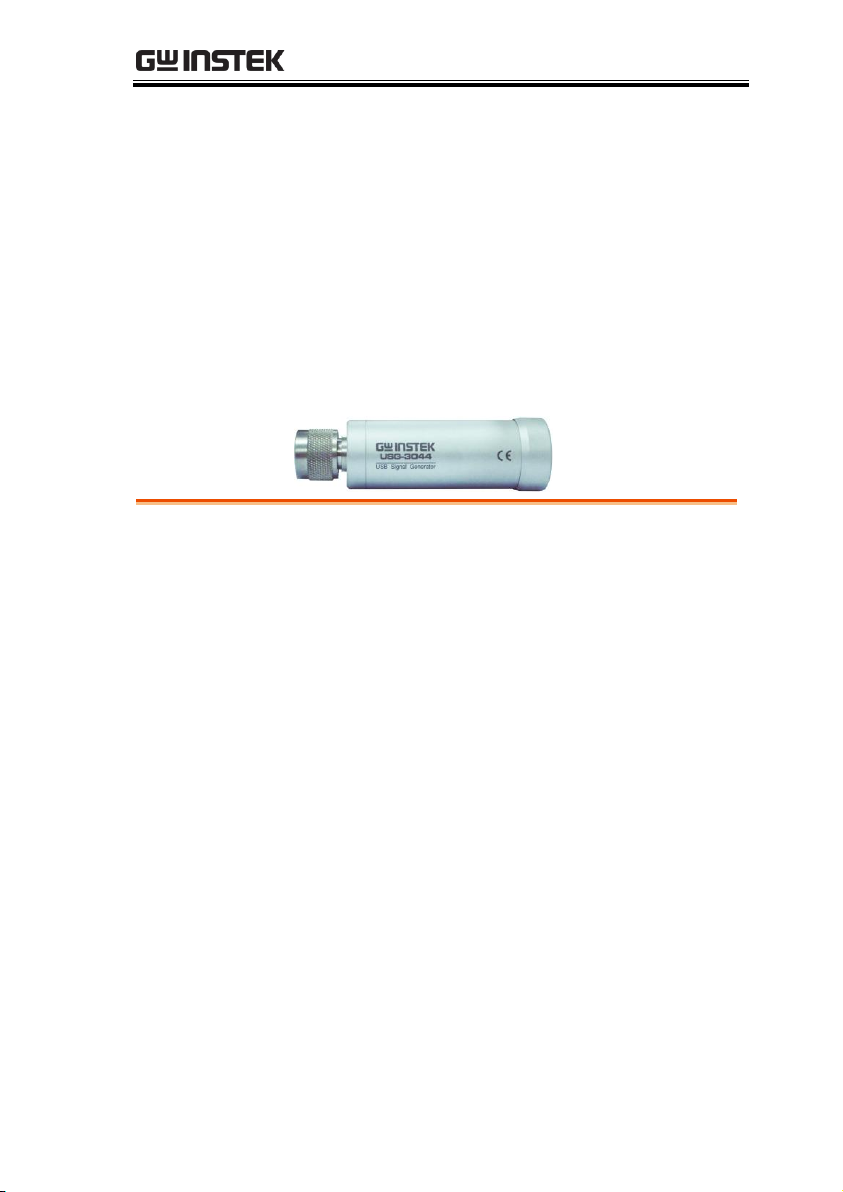
This chapter provides a brief overview of the USB
Signal Generator (hereafter referred to as „USG‟),
the package contents, instructions for first time
use and an introduction to the signal generator
display and tracking generator function.
5
Page 8

USG Series User Manual
Tracking Generator Software Installation
(Primary RF) ............................................. 20
6
Page 9

GETTING STARTED
Model
Frequency
Phase Noise
USG-LF44
34.5 MHz to 4.4 GHz
< -97dBc/Hz@1GHz, 10kHz
USG-0103
100 MHz to 300 MHz
< -100dBc/Hz@200MHz, 10kHz
USG-0818
800 MHz to 1.8 GHz
< -97dBc/Hz@1.3GHz, 10kHz
USG-2030
2.0 GHz to 3.0 GHz
< -93dBc/Hz@2.5GHz, 10kHz
USG-3044
3.0 GHz to 4.4 GHz
< -88dBc/Hz@3.7GHz, 10kHz
Performance
Five models supporting a frequency range from
34.5 MHz to 4.4 GHz
10kHz resolution
-30 dBm to 0 dBm output power
Features
Signal generator operation supports a plethora
USG Series Introduction
The USG series signal and tracking generators can be operated as
standalone continuous wave generators, or when paired to a PC
and the GSP-730 spectrum analyzer, they can be used as tracking
generators.
As continuous wave generators, the USG can be configured using
any java supported PC or an Android device. The device can
generate continuous wave, sweep, power sweep and frequency
hopping waveforms.
As a tracking generator, the USG can be connected to a PC using
dedicated software (Primary RF) to synchronize the USG with the
GSP-730 spectrum analyzer.
Series lineup
The USG series consists of 5 models, spanning a number of
different frequency ranges.
Main Features
7
Page 10
USG Series User Manual
of control devices:
Any java-enabled PC: Windows, Mac or Linux
PCs.
Any android device that supports USB OTG
(USB On The Go) operation (via Google Play).
Continuous wave, sweep wave, frequency
hopping wave, power sweep wave.
Standard
Accessories
Part number
Description
Region dependant
User manual CD
Region dependant
USB A to Mini USB cable
Standard
Accessories
Part number
Description
ADP-003
N female to SMA female adaptor
Package Contents and Standard Accessories
Optional Accessories
8
Page 11
GETTING STARTED
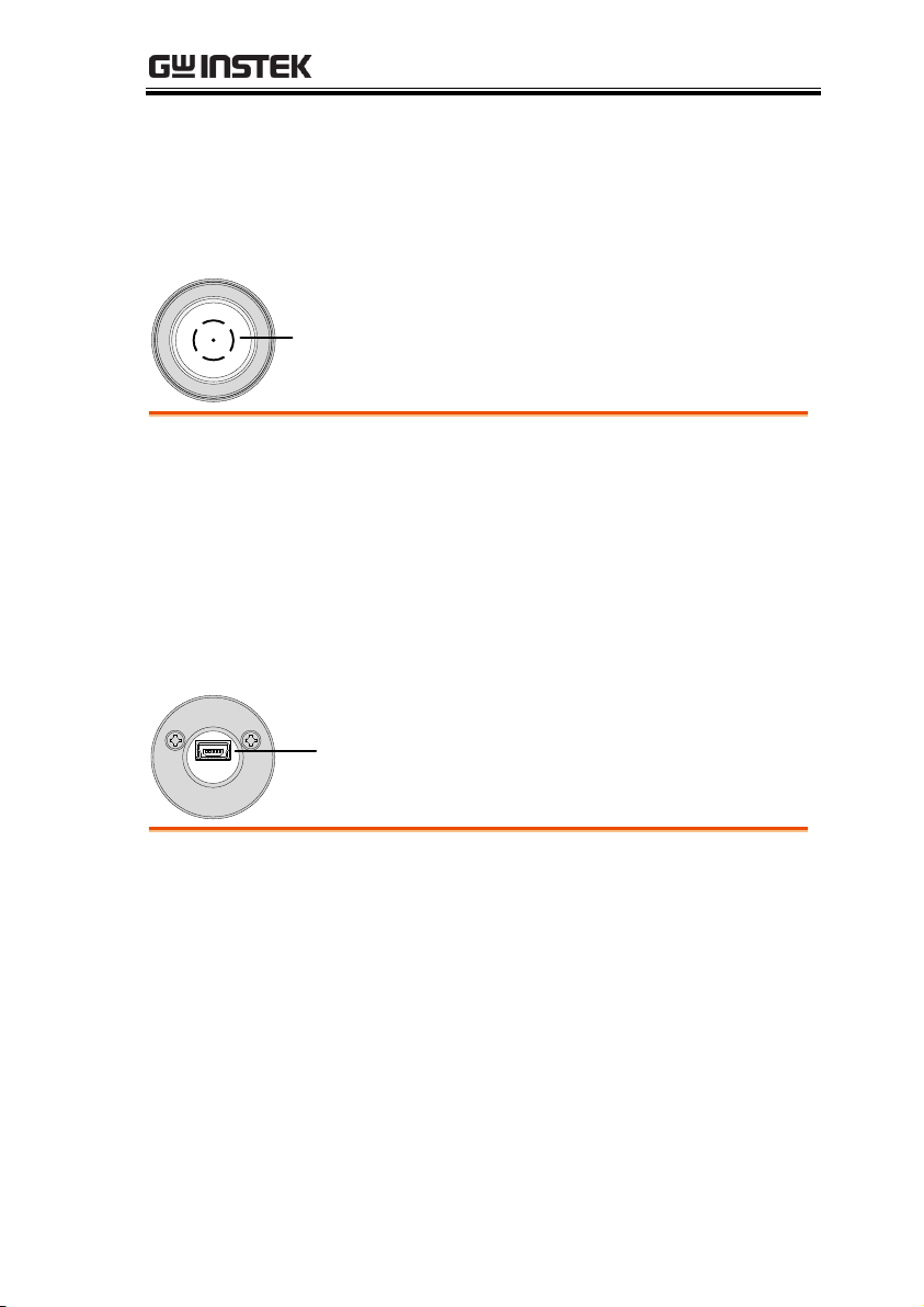
RF output
terminal
RF Output
Terminal
RF output port. Accepts RF outputs.
Output: 0 ~ -30dBm
Input impedance: 50Ω
N-type: male
Mini USB port
Mini USB port
Used to connect to a PC or Android device for
configuration or control.
When connected to power, the mini USB port will
be lit red.
Appearance
Front Face
Rear Face
9
Page 12
USG Series User Manual
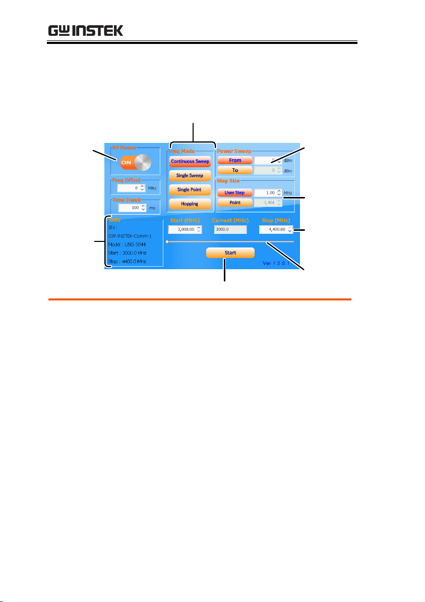
Power
indicator
Power
Sweep
Function
Mode
Start key
Offset and
time dwell
settings
Frequency
settings
System
infomation
Frequency
status bar
Step Size
Power Indicator
Turns the RF output on or off.
Function Mode
Chooses the type of function to be performed by
the USG: Continuous Sweep, Single Sweep, Single
Point or Hopping
Power Sweep
Sets the Start and Stop power level settings. The
From setting set the initial power level at the start
of the sweep and the To setting sets the final power
level at the end of the sweep.
Step Size
Sets the sweep step settings
Signal Generator Display - Java
10
Page 13
GETTING STARTED
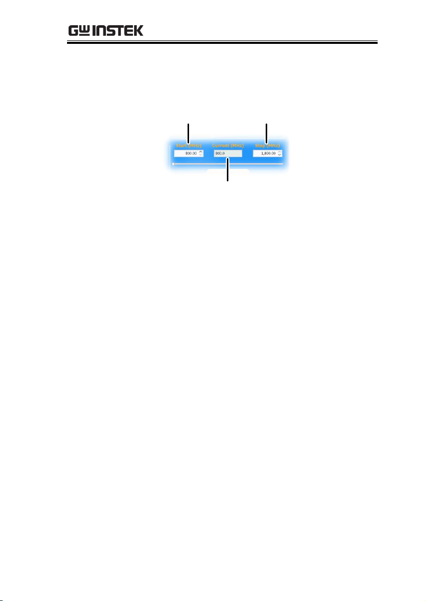
Frequency
Settings
Sets the basic start and stop frequency parameter
settings. It also displays the instantaneous
(current) output frequency, as shown below.
Start frequency Stop frequency
Current frequency
Frequency Status
Bar
When the output is on, the point on the frequency
status bar indicates the instantaneous frequency
that is being output. When the output is off, the
status bar can set the start and stop frequencies.
Start key
Pressing Start will output the selected function.
System
Information
The system information states the serial number,
model and frequency range specifications.
Frequency Offset
Settings
Offsets the frequency by ±50 kHz.
Time Dwell
Settings
The time dwell settings determine how long the
signal will stay (dwell) at each frequency point.
Step Size
The User Step and Point (inversely related) set the
step resolution of the single and continuous sweep
functions in hertz and number of points,
respectively.
11
Page 14
USG Series User Manual
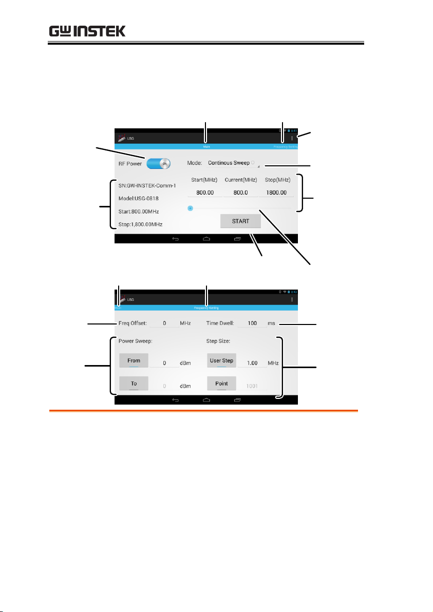
Power
indicator
Function
settings
Main
panel
Start key
Frequency
range
settings
System
infomation
Frequency
status bar
Frequency
offset
settings
To Frequency
Setting panel
About
To Main panel
Frequency
Setting panel
Time
Dwell
settings
Power
sweep
settings
Step size
settings
Power Indicator
Turns the RF output on or off.
System
Information
The system information states the serial number,
model and frequency range specifications.
Main panel
Indicates that the interface is in the Main panel.
To Frequency
Setting panel
Indicates that swiping to the left will go to the
Frequency Setting panel.
Signal Generator Display – Android App
12
Page 15
GETTING STARTED
Function Settings
Chooses the type of function to be performed by
the USG: Continuous Sweep, Single Sweep, Single
Point or Hopping.
Frequency Range
Settings
Sets the basic start and stop frequency parameter
settings. It also displays the instantaneous
(current) output frequency, as shown below.
Start frequency Stop frequency
Actual frequency
Frequency Status
Bar
When the output is on, the point on the frequency
status bar indicates the instantaneous frequency
that is being output. When the output is off, the
status bar can set the start and stop frequencies.
Start key
Pressing Start will output the selected function.
About
Pressing About will display the GNU lesser GPL
license requirements.
To Main panel
Indicates that swiping to the right will go to the
Main panel.
Frequency Setting
panel
Indicates that the interface is in the Frequency
Setting panel.
Frequency Offset
Settings
Offsets the frequency by ±50 kHz.
Power Sweep
Settings
Sets the start and stop power level settings. The
From setting sets the initial power level at the start
of the sweep, and the To setting sets the final
power level at the end of the sweep.
13
Page 16

USG Series User Manual
Time Dwell
Settings
The time dwell settings determine how long the
signal will stay (dwell) at each frequency point.
Step Size
Settings
The User Step and Point (inversely related) set the
step resolution of the single and continuous sweep
functions in hertz and number of points,
respectively.
14
Page 17

GETTING STARTED
USG Power Level
Point
GSP
Settings
Stop
Mark
Normalize Settings
Continuous
Sweep
Single
Sweep
Point
Sets the number of frequency points for sweep.
Mark
Sets the marker frequency.
GSP Settings
Sets the reference level, scale and start and stop
frequencies.
Power Level
Sets the USG output power level.
Normalize
Settings
Normalizes the USG output.
Single Sweep
Outputs a single sweep.
Continuous
Sweep
Outputs a continuous sweep.
Stop
Stops the sweep output.
Primary RF – Tracking Generator Function
15
Page 18

USG Series User Manual
Description
The USG connects via USB to a PC using a
virtual COM port driver.
For Linux and OS X systems, the USG device is
recognized as a virtual COM port device
automatically. A device driver does not need to be
installed for these systems.
For Microsoft Windows operating systems, the
USG will be recognized as a virtual COM port
device only after the USB driver is installed.
Requirements
Operating System: Windows XP, Vista, 7, 8*
Note
*Please note that for Windows 8, “Device driver
signature enforcement” must first be disabled
before the driver can be installed. See page 18 for
details.
Steps
1. Connect the USG to the PC using the USB Type
A - Mini-B cable.
If the PC asks for the driver, please go to step 5.
2. Open the Windows Device Manager. On
Windows 7 for example:
Start>Control Panel>Hardware and Sound>Device
Manager
First Time Use Instructions
The following instructions will go over all installation instructions
that are required to operate the USG from a PC or from an android
device.
Installing the USG USB Driver
16
Page 19

GETTING STARTED
3. From the device tree go to: Other devices>USB
Serial Port
The yellow error sign indicates that a driver has not
been installed.
4. Right-click USB Serial Port and select Update
Driver Software.
5. Select Browse my computer for driver software
when prompted.
Manually select the USG Driver from the User
Manual CD when prompted.
If the Windows Security pop-up appears,
choose Install this driver software anyway.
17
Page 20

USG Series User Manual
6. The USG will now become available in the
device tree under PORTS (COM & LPT).
Description
To install the USG USB driver on Windows 8
systems, you must first disable “Device driver
signature enforcement”. This procedure is
shown below.
Note
Applicable to Windows 8 only!
Steps
1. Go to the Charms bar Click on Settings
Click on Power Hold the SHIFT key and click
Restart Click Troubleshoot Advanced
Options Startup Settings Restart Select
7) Disable driver signature enforcement.
2. The PC will now restart.
3. After the PC restarts, it will now be possible to
install the USG USB driver on Windows 8 using
the procedure shown previously.
Disabling the Device Driver Signature Enforcement in
Windows 8
18
Page 21

GETTING STARTED
Description
The USG software for controlling the USG as a
signal generator can be found on the Google
Play store.
Note
Supported for Android 4.0 and above only.
Steps
1. Open Google Play on your Android device.
2. Enter USB Signal Generator in the Google Play
search bar.
3. Install the USB Signal generator mobile app
(GW Instek.Inc.)
4. The USG app will now be available in your
App Draw.
By default, the USG app will automatically
load each time the USG is attached to your
USB device.
Installing the USG Software from Google Play
19
Page 22

USG Series User Manual
Description
Primary RF is used in conjunction with the USG
as a tracking generator for the GSP-730.
Note:
Requirements
Only Windows operating systems (Windows XP,
Vista, 7, 8) can be used with the Primary RF
software.
Note: USB
Drivers
Before the tracking generator software can be
installed, the USG USB driver must first be
installed. See page 16 for details.
Note that the USB driver for the GSP-730’s USB
interface will be automatically installed when
installing the Primary RF software.
Note:
NI 488.2 Software
The tracking generator function requires National
Instruments NI 488.2 software to be installed. This
software is available on the NI website,
www.ni.com.
Driver installation
1. Open the User Manual CD and
click on PrimaryRF.msi.
2. The Primary RF Setup Wizard will appear.
Follow the prompts until it is all installed.
Note: If the Windows Security pop-up appears,
choose Install this driver software anyway.
Tracking Generator Software Installation (Primary RF)
20
Page 23

GETTING STARTED
3. Primary RF will now be available in the
Windows Start Menu.
21
Page 24

USG Series User Manual
Signal Generator Function ............................................... 23
Setup ~ PC ................................................ 23
Setup ~ Android Device ............................ 24
Frequency Function Mode ......................... 26
Selecting the Frequency ............................ 27
Selecting the Frequency Step Size ............. 28
Time Dwell ................................................ 29
Frequency Offset ....................................... 30
Selecting the Power Sweep ........................ 31
Turning the Output On.............................. 32
Tracking Generator Function (Primary RF Software) ......... 33
Setup ........................................................ 33
Tracking Generator Setup .......................... 34
Normalizing the Tracking Generator ......... 36
Using the Tracking Generator .................... 38
Save Results - CSV .................................... 39
Save Results - Print ................................... 40
OPERATION
22
Page 25

OPERATION
Description
The following chapter will show how to run the
Java based application and the how to connect
the USG to the PC.
Any Windows, Mac OS X or Linux PC that can
install the Java runtime library can be used to
operate the signal generator function.
Note
The Java runtime needs to be installed before
continuing. Visit www.java.com to download and
install the Java Runtime.
Note
For Windows, the USG USB driver must first be
installed. See page 16 for details. Mac OS X and
Linux systems do not need to install this driver.
Connection
1. Connect the USG to the RF port of the GSP-730.
2. Connect the PC to the USG using a Type A-
mini USB cable.
Signal Generator Function
The signal generator function can be controlled with PC using a
java program (using Windows, Mac OS X or Linux operating
systems) or with an Android device.
Setup ~ PC
23
Page 26

USG Series User Manual
3. Open USG_GUI_v1001.jar file (accessible on the
User Manual CD).
The USG_GUI_v1001 file doesn‟t need to be
installed.
4. If it is not already, turn the RF power on for the
USG.
RF Power
Description
The following chapter will show how to start
up and connect the USG to an Android device.
Note
Install the USB signal generator software before
connecting the USB to your Android device. See
page 18.
Connection
1. Connect the USG to the RF port of the GSP-730.
2. Connect the Android device to a USB OTG
cable.
3. Connect the OTG cable to the USG using a Type
A-mini USB cable.
Setup ~ Android Device
24
Page 27

OPERATION
4. By default, the USG app should load up when
the Android device is connected to the USG.
If the app does not automatically load up, go
to the app drawer and run the USB signal
generator app.
5. If it is not already, turn the RF power on for the
USG.
Note
If the USB cable is not connected properly, the
system information in the Main panel will show
“NONE”. In this case, re-insert the USB cable and
the OTG cable.
25
Page 28

USG Series User Manual
Description
There are four different frequency modes that
can be selected.
Java App Display
Function Mode
Android App
Display
Function Mode
Steps
1. In the Freq Mode panel(Java)/Mode drop-down
list(Android), select the frequency function
mode:
Continuous Sweep:
Outputs a continuous sweep
Single Sweep:
Outputs a single sweep
Single Point:
Outputs a single frequency
Hopping:
Frequency hops between
two frequencies
Frequency Function Mode
26
Page 29

OPERATION
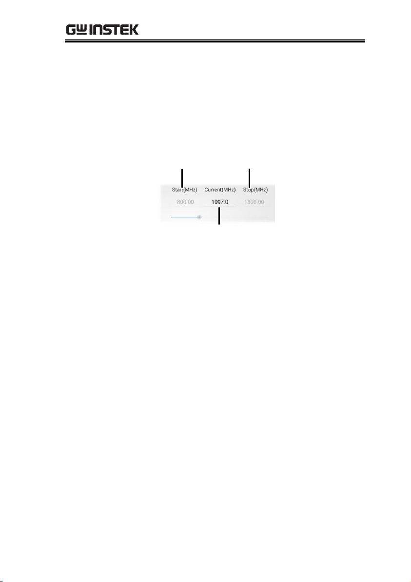
Description
Sets the Start and Stop frequency for the USG.
Java App Display
Start frequency
Current frequency
Frequency slider
Stop frequency
Current frequency
Android App
Display
Start frequency Stop frequency
Current frequency
Current frequency
Frequency slider
Steps
1. At the bottom of the screen set the Start and
Stop frequencies for the continuous sweep,
single sweep and hopping frequency modes.
For the Single Point frequency mode, only the
Start frequency can be set.
Note
The settable frequency range is limited by the USG
model type.
Selecting the Frequency
27
Page 30

USG Series User Manual
Description
The step size settings determine the number of
frequency points for the sweep modes.
Java App Display
Step size
Number of points
Android App
Display
Step size
Number of points
Steps
1. To set the span of each step of a sweep, press
User Step.
2. To set the number of discrete steps in a sweep,
press Point.
The number or points or the frequency span
of each step depends on the USG model.
User Step range
0.01MHz~ 100 MHz
Point range
(Frequency span of USG
model / User Step
range) + 1 = Point range
Selecting the Frequency Step Size
28
Page 31

Time Dwell
Description
The Time Dwell setting determines the amount
of time between each point in a sweep.
Java App Display
Time Dwell
Android App
Display
Time Dwell
Steps
1. Press Time Dwell to set the amount of time
between each step in milliseconds.
The Time Dwell setting range depends on the
on the USG model.
Time Dwell
1ms~ 1000ms
Note
The minimum step time is automatically set by the
PC software. A 1ms Time Dwell can only be
achieved with a fast system.
OPERATION
29
Page 32

USG Series User Manual
Description
The Frequency Offset setting will offset the
frequency by ±0.05 MHz.
Java App Display
Freq Offset
Android App
Display
Frequency Offset
Steps
1. Press Freq Offset to set an offset to the
frequency settings.
Offset
± 0.05 MHz
Frequency Offset
30
Page 33

OPERATION
Description
Sets the power level for the start and stop
frequencies.
For the sweep functions, sets the power level
from the Start frequency to the Stop frequency.
For the Single Point function, the From setting
sets the initial power level and the To setting, if
needed, sets the final power level.
For the Hopping function, the From setting sets
the power level of the Start Frequency and the
To setting set the power level at the Stop
frequency.
Java App Display
From setting
To setting
Android App
Display
From settings
To settings
Selecting the Power Sweep
31
Page 34

USG Series User Manual
Steps
1. To set the initial power level, press From.
2. To set the final power level press To.
If you only want one power level, only set the
From setting.
Power level range
0dBm ~ -30dBm
Steps
After all the settings have been set press Start
to turn on the output on.
For the single sweep function, press Start for
each single sweep.
Java App Display
Start
Android App
Display
Start
Turning the Output On
32
Page 35

OPERATION
Note
Please note that the Primary RF software has
multiple functions and can be used for purposes
other than as tracking generator software for the
GSP-730. The other software functions are beyond
the scope of this manual and will not be detailed.
Description
The following chapter will show how to
connect the USG to the GSP-730 and to the host
PC when using the USG as a tracking
generator. To use the USG as a tracking
generator, the Primary RF software must be
used. See page 20 for installation details.
Connection
1. Connect the USG to the RF port of the GSP-730.
2. Connect the PC to the USG using a Type A-
mini USB cable.
3. Connect the PC to the rear-panel USB B port on
the GSP-730 using a Type A-Type B USB cable.
Tracking Generator Function (Primary RF
Software)
The Primary RF software can be used as a tracking generator for
the GSP-730 to track the frequency response of a DUT.
Setup
33
Page 36

USG Series User Manual
Description
The section will describe how to use the USG as
a tracking generator for the GSP-730.
Operation
1. Launch PrimaryRF.
2. Click on the large GSP-730 button at the top of
the window.
The spectrum analyzer settings will be shown*
when the connection to the GSP-730 is working.
Note
*Note: The above GSP-730 frequency and
amplitude settings as well as the Capture function
are not used for the tracking generator function
and are thus not used in this manual. Using these
functions is beyond the scope of this user manual.
Tracking Generator Setup
34
Page 37

OPERATION
3. Press Action(A) and select USG as TG for GSP-
730.
A new window will open for the tracking
generator options.
4. Press Point and set the number of frequency
points that will be used in the sweep.
5. Press Mark and set the marker frequency.
The marker frequency and amplitude will be
shown at the top of the grid.
35
Page 38

USG Series User Manual
6. Under the GSP-730 panel set the basic spectrum
analyzer settings:
Ref.Level: -40 ~ 20 dBm
Scale: 1~10
Start frequency: Dependent on the connected
USG model
Stop Frequency: Dependent on the connected
USG model
7. Set the USG power level:
Power Level: 0 ~ -30 dBm
Description
The tracking generator should first be
normalized before a DUT is connected to the
USG.
Operation
1. Setup Primary RF as shown above.
Normalizing the Tracking Generator
36
Page 39

OPERATION
2. Press Single Sweep and perform a single sweep.
It may take some time to complete a full sweep,
depending on the fixed RBW (1MHz) and span
100MHz settings.
The Normalize panel will be selectable after the
first sweep is performed.
3. Press Normalize after a full sweep has been
performed. The Normalize radio button will
then automatically be set to ON.
This will normalize the USG output for the
Primary RF software.
4. Set the normalized amplitude level.
Normalize: 0 ~ -30dBm.
Display
Normalized spectrum
USG spectrum
37
Page 40

USG Series User Manual
Note
Before performing normalization, make sure the
USG has been on for at least 30 minutes to
eliminate drift from effecting the normalization.
Description
After normalization is performed, the USG can
be used to measure the frequency response of a
DUT.
DUT
Operation
1. Remove the USG from the GSP-730 and put the
DUT between the USG and the GSP-730 RF
ports.
2. Press Sweep or Continuous sweep to get the
frequency response of the DUT.
Display
Normalized spectrum
Frequency response
Example: Low pass filter frequency response.
Using the Tracking Generator
38
Page 41

OPERATION
Description
The spectrum results on GSP-730 can be saved
as a CSV file.
CSV File Format
Center frequency
AmplitudePoint number
Operation
1. Perform either a sweep or a continuous sweep,
as shown above. See page 38 for details.
2. After the sweep has completed, press the disk
drive icon on the top left-hand side.
Save icon
3. A pop-up window will now appear. Choose a
file name and directory and select Save.
Save Results - CSV
39
Page 42

USG Series User Manual
Description
The spectrum results on the GSP-730 can be
saved as a PDF or printed.
Print Format
Results are printed in an inverted color format.
Operation
1. Perform either a sweep or a continuous sweep,
as shown above. See page 38 for details.
2. After the sweep has completed, press the print
icon on the top left-hand side.
Print icon
3. A pop-up window will now appear. Choose a
printer or choose to save as a PDF.
4. Press Print to print the results.
Save Results - Print
40
Page 43

FAQ
•
The USG will not connect to the PC.
•
Primary RF will not allow me to connect to the GSP-730.
•
The performance does not match the specification.
FAQ
The USG will not connect to the PC.
If you are running a Windows system, make sure that the USG USB
driver has been installed correctly, see page 16 for details. If you are
running Windows 8, please make sure that “Device driver
signature enforcement” is disabled before installing the driver, see
page 18 for details.
Primary RF will not allow me to connect to the GSP-730.
Make sure that all the USB cables from the USG and GSP-730 are
connected correctly, then make sure that the NI.488.2 software is
installed before Primary RF is installed. See page 20 for installation
details.
The performance does not match the specification.
Make sure the device is powered On for at least 30 minutes, within
+20°C~+30°C. This is necessary to stabilize the unit to match the
specification.
For more information, contact your local dealer or GWInstek at
www.gwinstek.com / marketing@goodwill.com.
41
Page 44

USG Series User Manual
Frequency Range
34.5 MHz to 4.4 GHz
Output Power
-30 dBm to 0 dBm
in 1 dB steps
Internal Reference
25 MHz
aging ±1 ppm at first year
Frequency Accuracy
± 100 Hz
at 100 MHz, 0 dBm Output
Resolution
10 kHz
Output Control
On / Off
On / Off Isolation
≤ -75 dBc
Mode Control
Fixed Frequency / Single Sweep / CW Sweep / Hopping
Step Dwell
≤ 1000 ms in 1* ms steps
Frequency Offset
-50 kHz to 50 kHz in 10 kHz steps
Amplitude Absolute
Accuracy
0 dBm ± 1 dB typical
at 2200MHz, 0 dBm Output
Output Flatness
± 3.5 dB, ref. to
2200MHz
at 0 dBm Output
Phase noise
< -97 dBc/Hz
10 kHz offset @ 1.0 GHz, typical
-100 dBc/Hz
< -107 dBc/Hz
100 kHz offset @ 1.0 GHz,
typical -110dBc/Hz
2nd Harmonics
0 dB Attenuation
≤ -15 dBc, typical
34.5 MHz to 2.0 GHz,
fundamental
≤ -10 dBc, typical
2.0 GHz to 3.0 GHz,
fundamental
≤ -25 dBc, typical
3.0 GHz to 4.4 GHz,
fundamental
APPENDIX
USG Specifications
The specifications apply when the USG is powered on for at least
30 minutes to warm-up to a temperature of 20˚C to 30˚C, unless
specified otherwise.
USG-LF44
42
Page 45

3rd Harmonics
0 dB Attenuation
≤ -5 dBc, typical
34.5 MHz to 2.0 GHz,
fundamental
≤ -20 dBc, typical
2.0 GHz to 3.0 GHz,
fundamental
≤ -40 dBc, typical
3.0 GHz to 4.4 GHz,
fundamental
Spurious related to
Resolution settings
(Single Point Mode)
≤ -30 dBc, typical
Resolution < 1 MHz
≤ -65 dBc, typical
Resolution ≥ 1 MHz
Spurious related to the
fundamental output
(Single Point Mode)
≤ -60 dBc, typical
USG-0103
Frequency Range
100 MHz to 300 MHz
Output Power
-30 dBm to 0 dBm
in 1 dB steps
Internal Reference
25 MHz
aging ±1 ppm at first year
Frequency Accuracy
± 100 Hz
at 100MHz, 0 dBm Output
Resolution
10 kHz
Output Control
On / Off
On / Off Isolation
≤ -75 dBc
Mode Control
Fixed Frequency / Single Sweep / CW Sweep / Hopping
Step Dwell
≤ 1000 ms in 1* ms steps
Frequency Offset
-50 kHz to 50 kHz in 10 kHz steps
Amplitude Absolute
Accuracy
-1.2 dBm ± 1 dB
typical
at 150 MHz, 0 dBm Output
Output Flatness
± 1 dB, ref. to 150
MHz
at 0 dBm Output
Phase noise
< -100 dBc/Hz,
typical
10 kHz offset @ 200 MHz
< -110 dBc/Hz
100 kHz offset @ 200 MHz
2nd Harmonics
0 dB Attenuation
≤ -45 dBc, typical
> 100 MHz, fundamental
3rd Harmonics
0 dB Attenuation
≤ -7dBc, typical
≤ 150 MHz, fundamental
≤ -35 dBc, typical
> 150 MHz, fundamental
Spurious related to
Resolution settings
(Single Point Mode)
≤ -30 dBc, typical
Resolution < 1 MHz
≤ -65 dBc, typical
Resolution ≥ 1 MHz
Spurious related to the
fundamental output
(Single Point Mode)
≤ -60 dBc, typical
APPENDIX
43
Page 46

USG-0818
Frequency Range
800 MHz to 1.8 GHz
Output Power
-30 dBm to 0 dBm
in 1 dB steps
Internal Reference
25 MHz
aging ±1 ppm at first year
Frequency Accuracy
± 800 Hz
at 800MHz, 0 dBm Output
Resolution
10 kHz
Output Control
On / Off
On / Off Isolation
≤ -75 dBc
Mode Control
Fixed Frequency / Single Sweep / CW Sweep / Hopping
Step Dwell
≤ 1000 ms in 1* ms steps
Frequency Offset
-50 kHz to 50 kHz in 10 kHz steps
Amplitude Absolute
Accuracy
-0.8 dBm ± 1 dB
typical
at 1000 MHz, 0 dBm Output
Output Flatness
± 1 dB, ref. to
1000MHz
at 0 dBm Output
Phase noise
< -97 dBc/Hz
10 kHz offset @ 1.3 GHz
< -102 dBc/Hz
100 kHz offset @ 1.3 GHz
2nd Harmonics
0 dB Attenuation
≤ -25 dBc, typical
>800 MHz, fundamental
3rd Harmonics
0 dB Attenuation
≤ -25 dBc, typical
≤900 MHz, fundamental
≤ -35 dBc, typical
>900 MHz, fundamental
Spurious related to
Resolution settings
(Single Point Mode)
≤ -30 dBc, typical
Resolution < 1 MHz
≤ -65 dBc, typical
Resolution ≥ 1 MHz
Spurious related to the
fundamental output
(Single Point Mode)
≤ -65 dBc, typical
Frequency Range
2.0 GHz to 3.0 GHz
Output Power
-30 dBm to 0 dBm
in 1 dB steps
Internal Reference
25 MHz
aging ±1 ppm at first year
Frequency Accuracy
± 2 kHz
at 2 GHz, 0 dBm Output
Resolution
10 kHz
Output Control
On / Off
On / Off Isolation
≤ -75 dBc
Mode Control
Fixed Frequency / Single Sweep / CW Sweep / Hopping
Step Dwell
≤ 1000 ms in 1* ms steps
Frequency Offset
-50 kHz to 50 kHz in 10 kHz steps
USG Series User Manual
USG-2030
44
Page 47

Amplitude Absolute
Accuracy
0 dBm ± 1 dB typical
at 2500 MHz, 0 dBm Output
Output Flatness
± 1 dB, ref. to
2500MHz
at 0 dBm Output
Phase noise
< -93 dBc/Hz
10 kHz offset @ 2.5 GHz
< -100 dBc/Hz
100 kHz offset @ 2.5 GHz
2nd Harmonics
0 dB Attenuation
≤ -30 dBc, typical
2.0 GHz to 3.0 GHz,
fundamental
3rd Harmonics
0 dB Attenuation
≤ -45 dBc, typical
2.0 GHz to 3.0 GHz,
fundamental
Spurious related to
Resolution settings
(Single Point Mode)
≤ -30 dBc, typical
Resolution < 1MHz
≤ -65 dBc, typical
Resolution ≥ 1MHz
Spurious related to the
fundamental output
(Single Point Mode)
≤ -65 dBc, typical
USG-3044
Frequency Range
3.0 GHz to 4.4 GHz
Output Power
-30 dBm to 0 dBm
in 1 dB steps
Internal Reference
25 MHz
aging ±1 ppm at first year
Frequency Accuracy
± 3 kHz
at 3 GHz, 0 dBm Output
Resolution
10 kHz
Output Control
On / Off
On / Off Isolation
≤ -75 dBc
Mode Control
Fixed Frequency / Single Sweep / CW Sweep / Hopping
Step Dwell
≤ 1000 ms in 1* ms steps
Frequency Offset
-50 kHz to 50 kHz in 10 kHz steps
Amplitude Absolute
Accuracy
1 dBm ± 1 dB typical
at 3300 MHz, 0 dBm Output
Output Flatness
± 2 dB, ref. to
3300MHz
at 0 dBm Output
Phase noise
< -88 dBc/Hz
10 kHz offset @ 3.7 GHz
< -94 dBc/Hz
100 kHz offset @ 3.7 GHz
2nd Harmonics
0 dB Attenuation
≤ -25 dBc, typical
3.0 GHz to 4.4 GHz,
fundamental
3rd Harmonics
0 dB Attenuation
≤ -40 dBc, typical
3.0 GHz to 4.4 GHz,
fundamental
APPENDIX
45
Page 48

USG Series User Manual
Spurious related to
Resolution settings
(Single Point Mode)
≤ -30 dBc, typical
Resolution < 1MHz
≤ -65 dBc, typical
Resolution ≥ 1MHz
Spurious related to the
fundamental output
(Single Point Mode)
≤ -65 dBc, typical
*: Minimum step depands on the computer being used. This min. step will be
automatically adjusted by the PC software. 1ms is achieved on a faster system.
Software for PC:
a. Primary RF supports operating system: Windows 2000/XP/Vista/7/8
b. Java USG Control Panel: Windows 2000/XP/Vista/7/8 Linux/OS X
Software for mobile device:
For Android 4.0 and higher with OTG*
Interface
USB 2.0
USB Connector Type
Mini-B
Supply Voltage
5V
nominal
RF Connector Type
N-type male
Impedance
50 ohm
nominal
Output VSWR
< 1.5:1
Output level @ -30dBm
Max. DC voltage
connected to output
+/-25VDC
Max. Reverse Power
+30dBm
*Warning: Some Android devices with OTG support cannot run the USG app due
to the OTG driver modifications by vendors.
Common Specifications
46
Page 49

APPENDIX
20.8
102.4
29.5
102.4
20.8
27.8
Scale :mm
USG Dimensions
47
Page 50

USG Series User Manual
Type of Product: USB Signal Generator
Model Number: USG-LF44, USG-0103, USG-0818, USG-2030, USG-3044
EN 61326-1:
EN 61326-2-1:
Electrical equipment for measurement, control and
laboratory use –– EMC requirements (2006)
Conducted and Radiated Emissions
EN 55011:2009+A1:2010 Group 1 Class A
Electrostatic Discharge
EN 61000-4-2: 2009
-------------------------
Radiated Immunity
EN 61000-4-3: 2006+A1: 2008+A2 :2010
-------------------------
Voltage Dip/ Interruption
EN 61000-4-11: 2004
Declaration of Conformity
We
GOOD WILL INSTRUMENT CO., LTD.
No. 7-1, Jhongsing Rd, Tucheng Dist., New Taipei City 236, Taiwan
GOOD WILL INSTRUMENT (SUZHOU) CO., LTD.
No. 69 Lushan Road, Suzhou New District Jiangsu, China.
declare that the below mentioned products
are herewith confirmed to comply with the requirements set out in the
Council Directive on the Approximation of the Laws of the Member States
relating to Electromagnetic Compatibility (2004/108/EEC).
For the evaluation regarding the Electromagnetic Compatibility, the
following standards were applied:
◎ EMC
48
Page 51

INDEX
INDEX
Accessories ................................... 8
Caution symbol ............................ 2
Cleaning the instrument ............. 3
Declaration of conformity ......... 48
Display diagram
Android .......................................... 12
Java ................................................. 10
Primary RF
Tracking generator ...........................15
Disposal instructions ................... 4
Disposal symbol ........................... 2
Environment
Safety instruction ............................ 3
FAQ ............................................. 41
First time use instructions ........ 16
Front face ...................................... 9
Ground
Symbol .............................................. 2
List of features .............................. 7
Marketing
Contact ........................................... 41
Model differences ........................ 7
NI Software
NI 488.2 software .......................... 20
Operation
Signal Generator ........................... 23
Power on/off
Safety instruction ............................ 3
Primary RF
Installation ..................................... 20
Rear face ........................................ 9
Service operation
About disassembly ......................... 3
Contact ........................................... 41
Signal Generator
Android setup ............................... 24
Frequency ...................................... 27
Frequency offset ........................... 30
Function mode .............................. 26
Output ............................................ 32
PC setup ......................................... 23
Power sweep ................................. 31
Step size ......................................... 28
Time dwell ..................................... 29
Specifications .............................. 42
Common ........................................ 46
Dimensions .................................... 47
USG-0103 ....................................... 43
USG-0818 ....................................... 44
USG-2030 ....................................... 44
USG-3044 ....................................... 45
USG-LF44 ....................................... 42
Tracking Generator
normalizing ................................... 36
operation ........................................ 38
Primary RF setup .......................... 33
Print results ................................... 40
save results .................................... 39
Setup
hardware ........................................... 33
software ............................................. 34
USB driver
Installation ............................... 16, 18
USG
Google Play installation .............. 19
Warning symbol ........................... 2
49
 Loading...