

GW Instek PSU 6-200, PSU 20-76, PSU 40-38, PSU 12.5-120, PSU 100-15 Programming Manual
...
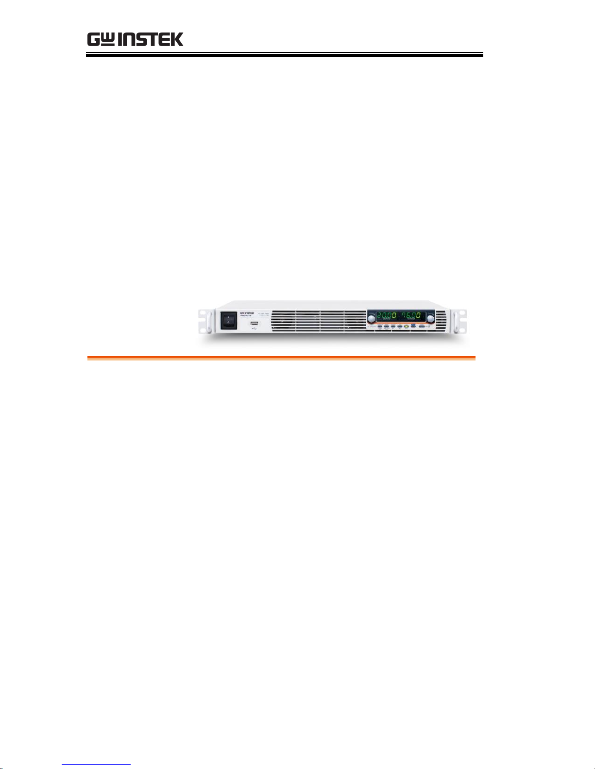
Programmable DC Power Supply
PSU Series
PROGRAMMING MANUAL
ISO-9001 CERTIFIED MANUFACTURER

This manual contains proprietary information, which is protected by
copyright. All rights are reserved. No part of this manual may be
photocopied, reproduced or translated to another language without
prior written consent of Good Will company.
The information in this manual was correct at the time of printing.
However, Good Will continues to improve products and reserves the
rights to change specification, equipment, and maintenance
procedures at any time without notice.
Good Will Instrument Co., Ltd.
No. 7-1, Jhongsing Rd., Tucheng Dist., New Taipei City 236, Taiwan.

Table of Contents
3
Table of Contents
SAFETY INSTRUCTIONS .................................................. 4
GETTING STARTED .......................................................... 8
PSU Series Overview .............................. 9
Appearance .......................................... 14
Configuration Settings ......................... 22
REMOTE CONTROL ....................................................... 32
Interface Configuration ........................ 34
Command Syntax ................................. 63
Command List ..................................... 67
Status Register Overview ................... 127
Error List ........................................... 140
APPENDIX .................................................................... 149
PSU Default Settings ......................... 149
Error Messages & Messages .............. 151
LED ASCII Table Character Set ........... 153
INDEX .......................................................................... 154
PSU Programming Manual
4
SAFETY INSTRUCTIONS
This chapter contains important safety
instructions that you must follow during
operation and storage. Read the following before
any operation to insure your safety and to keep
the instrument in the best possible condition.
Safety Symbols
These safety symbols may appear in this manual or on the
instrument.
WARNING
Warning: Identifies conditions or practices that
could result in injury or loss of life.
CAUTION
Caution: Identifies conditions or practices that
could result in damage to the PSU or to other
properties.
DANGER High Voltage
Attention Refer to the Manual
Protective Conductor Terminal
Earth (ground) Terminal
SAFETY INSTRUCTIONS
5
Do not dispose electronic equipment as unsorted
municipal waste. Please use a separate collection
facility or contact the supplier from which this
instrument was purchased.
Safety Guidelines
General
Guideline
CAUTION
Do not place any heavy object on the PSU.
Avoid severe impact or rough handling that
leads to damaging the PSU.
Do not discharge static electricity to the PSU.
Use only mating connectors, not bare wires, for
the terminals.
Do not block the cooling fan opening.
Do not disassemble the PSU unless you are
qualified.
(Measurement categories) EN61010-1:2010 and EN61010-2-030
specifies the measurement categories and their requirements as
follows. The PSU falls under category II.
Measurement category IV is for measurement performed at the
source of low-voltage installation.
Measurement category III is for measurement performed in the
building installation.
Measurement category II is for measurement performed on the
circuits directly connected to the low voltage installation.
0 is for measurements performed on circuits not directly
connected to Mains.
Power Supply
WARNING
AC Input voltage range: 85Vac~265Vac
Frequency: 47Hz to 63Hz
To avoid electrical shock connect the protective
grounding conductor of the AC power cord to
an earth ground.
PSU Programming Manual
6
Cleaning the PSU
Disconnect the power cord before cleaning.
Use a soft cloth dampened in a solution of mild
detergent and water. Do not spray any liquid.
Do not use chemicals containing harsh material
such as benzene, toluene, xylene, and acetone.
Operation
Environment
Location: Indoor, no direct sunlight, dust free,
almost non-conductive pollution (Note below)
Relative Humidity: 20%~ 85% (no condensation)
Altitude: < 2000m
Temperature: 0°C to 50°C
(Pollution Degree) EN61010-1:2010 and EN61010-2-030 specifies
the pollution degrees and their requirements as follows. The PSU
falls under degree 2.
Pollution refers to “addition of foreign matter, solid, liquid, or
gaseous (ionized gases), that may produce a reduction of dielectric
strength or surface resistivity”.
Pollution degree 1: No pollution or only dry, non-conductive
pollution occurs. The pollution has no influence.
Pollution degree 2: Normally only non-conductive pollution
occurs. Occasionally, however, a temporary conductivity caused
by condensation must be expected.
Pollution degree 3: Conductive pollution occurs, or dry, non-
conductive pollution occurs which becomes conductive due to
condensation which is expected. In such conditions, equipment
is normally protected against exposure to direct sunlight,
precipitation, and full wind pressure, but neither temperature
nor humidity is controlled.
Storage
environment
Location: Indoor
Temperature: -25°C to 70°C
Relative Humidity: ≤90%(no condensation)
Disposal
Do not dispose this instrument as unsorted
municipal waste. Please use a separate collection
facility or contact the supplier from which this
instrument was purchased. Please make sure
discarded electrical waste is properly recycled to
reduce environmental impact.
SAFETY INSTRUCTIONS
7
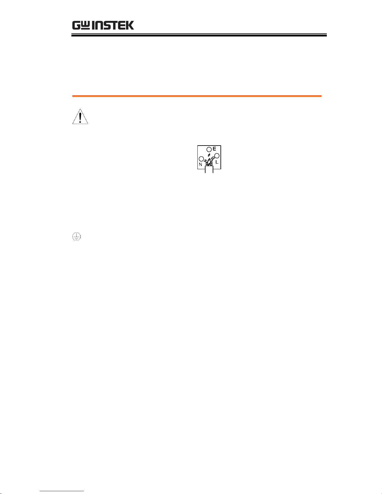
Power cord for the United Kingdom
When using the power supply in the United Kingdom, make sure
the power cord meets the following safety instructions.
NOTE: This lead/appliance must only be wired by competent persons
WARNING: THIS APPLIANCE MUST BE EARTHED
IMPORTANT: The wires in this lead are coloured in accordance with the
following code:
Green/ Yellow:
Earth
Blue:
Neutral
Brown:
Live (Phase)
As the colours of the wires in main leads may not correspond with
the coloured marking identified in your plug/appliance, proceed
as follows:
The wire which is coloured Green & Yellow must be connected to
the Earth terminal marked with either the letter E, the earth symbol
or coloured Green/Green & Yellow.
The wire which is coloured Blue must be connected to the terminal
which is marked with the letter N or coloured Blue or Black.
The wire which is coloured Brown must be connected to the
terminal marked with the letter L or P or coloured Brown or Red.
If in doubt, consult the instructions provided with the equipment
or contact the supplier.
This cable/appliance should be protected by a suitably rated and
approved HBC mains fuse: refer to the rating information on the
equipment and/or user instructions for details. As a guide, a cable
of 0.75mm2 should be protected by a 3A or 5A fuse. Larger
conductors would normally require 13A types, depending on the
connection method used.
Any exposed wiring from a cable, plug or connection that is
engaged in a live socket is extremely hazardous. If a cable or plug is
deemed hazardous, turn off the mains power and remove the cable,
any fuses and fuse assemblies. All hazardous wiring must be
immediately destroyed and replaced in accordance to the above
standard.
PSU Programming Manual
8
GETTING STARTED
This chapter describes the power supply in a
nutshell, including its main features and front /
rear panel introduction. After going through the
overview, please read the theory of operation to
become familiar with the operating modes,
protection modes and other safety considerations.
PSU Series Overview .................................................. 9
Series lineup ........................................................................................ 9
Main Features ................................................................................... 10
Accessories ........................................................................................ 11
Appearance .............................................................. 14
PSU Series Front Panel ................................................................... 14
PSU Series Display and Operation Panel .................................... 17
Rear Panel .......................................................................................... 19
Configuration Settings ............................................. 22
Setting Normal Function Settings ................................................. 22
Setting Power On Configuration Settings ................................... 24
Configuration Table ......................................................................... 26
GETTING STARTED
9
PSU Series Overview
Series lineup
The PSU series consists of 10 models, covering a number of
different current, voltage and power capacities:
Model name
Voltage Rating1
Current Rating2
Power
PSU 6-200
6V
200A
1200W
PSU 12.5-120
12.5V
120A
1500W
PSU 20-76
20V
76A
1520W
PSU 40-38
40V
38A
1520W
PSU 60-25
60V
25A
1500W
PSU 100-15
100V
15A
1500W
PSU 150-10
150V
10A
1500W
PSU 300-5
300V
5A
1500W
PSU 400-3.8
400V
3.8A
1520W
PSU 600-2.6
600V
2.6A
1560W
1
Minimum voltage guaranteed to 0.2% of rating voltage.
2
Minimum current guaranteed to 0.4% of rating current.

PSU Programming Manual
10
Main Features
Performance
High power density: 1500W in 1U
Universal input voltage 85~265Vac, continuous
operation.
Output voltage up to 600V, current up to 200A.
Features
Active power factor correction.
Parallel master/slave operation with active
current sharing.
Remote sensing to compensate for voltage drop
in load leads.
19" rack mounted ATE applications.
A built-in Web server.
OVP, OCP and OHP protection.
Preset memory function.
Adjustable voltage and current slew rates.
Bleeder circuit ON/OFF setting.
CV, CC priority start function. (prevents
overshoot with output ON)
Supports test scripts.
Interface
Built-in RS-232/485, LAN and USB interface.
Analog output programming and monitoring.
Optional interfaces: GPIB, Isolated Voltage (0-
5V/0-10V) and Isolated Current (4-20mA)
programming and monitoring interface.
(Factory options)

GETTING STARTED
11
Accessories
Before using the PSU power supply unit, check the package
contents to make sure all the standard accessories are included.
Standard
Accessories
Part number
Description
Qty.
Output terminal cover
1
Analog connector plug kit
1
Output terminal M8 bolt set
(6V~60V model)
1
Input terminal cover
1
Power Cord
1
82GW1SAFE0M*1
Safety Guide
1
62SB-8K0HD1*1
1U Handle, ROHS
2 62SB-8K0HP1*1
1U BRACKET (LEFT), RoHS
1
62SB-8K0HP2*1
1U BRACKET (RIGHT), RoHS
1
CD ROM
User manual, Programming
manual
1 set
82SU-PSU00K*1
Packing list
82GW-00000C*1
* CTC GW/INSTEK JAPAN
USE ,RoHS
1
Factory Installed
Options
Part number
Description
PSU-GPIB
GPIB interface
PSU-ISO-V
Voltage programming isolated
analog interface
PSU-ISO-I
Current programming isolated
analog interface
PSU-001
Front Panel Filter Kit (Operation
Temperature is guaranteed to
40˚C)

PSU Programming Manual
12
Optional
Accessories
Part number
Description
PSU-01C
Cable for 2 units of PSU-Series in
parallel mode connection
PSU-01B
Bus Bar for 2 units of PSU-Series in
parallel mode connection
PSU-01A
Joins a vertical stack of 2 PSU units
together. 2U-sized handles x2, joining
plates x2.
PSU-02C
Cable for 3 units of PSU-Series in
parallel mode connection
PSU-02B
Bus Bar for 3 units of PSU-Series in
parallel mode connection
PSU-02A
Joins a vertical stack of 3 PSU units
together. 3U-sized handles x2, joining
plates x2.
PSU-03C
Cable for 4 units of PSU-Series in
parallel mode connection
PSU-03B
Bus Bar for 4 units of PSU-Series in
parallel mode connection
PSU-03A
Joins a vertical stack of 4 PSU units
together. 4U-sized handles x2, joining
plates x2.
PSU-232
RS232 cable with DB9 connector kit.
It Includes RS232 cable with DB9
connector, RS485 used master cable
(gray plug), slave cable (black plug)
and end plug terminal.
PSU-485
RS485 cable with DB9 connector kit.
It Includes RS485 cable with DB9
connector, RS485 used master cable
(gray plug), slave cable (black plug)
and end plug terminal.
GRM-001
Rack-mount slides (General Devices
P/N: C-300-S-116-RH-LH)

GETTING STARTED
13
GTL-246
USB Cable 2.0-A-B Type, Approx. 1.2M
GPW-001
Power Cord SJT 12AWG/3C, 3m MAX
Length, 105 ºC, RNB5-5*3P UL/CSA
type
GPW-002
Power Cord H05W-F 1.5mm2/3C, 3m
MAX Length, 105 ºC, RNB5-5*3P VDE
type
GPW-003
Power Cord VCTF 3.5mm2/3C, 3m
MAX Length, 105 ºC, RNB5-5*3P PSE
type
Download
Name
Description
psu_cdc.inf
PSU USB driver
Other
Name
Description
Certificate of traceable calibration
PSU Programming Manual
14
Appearance
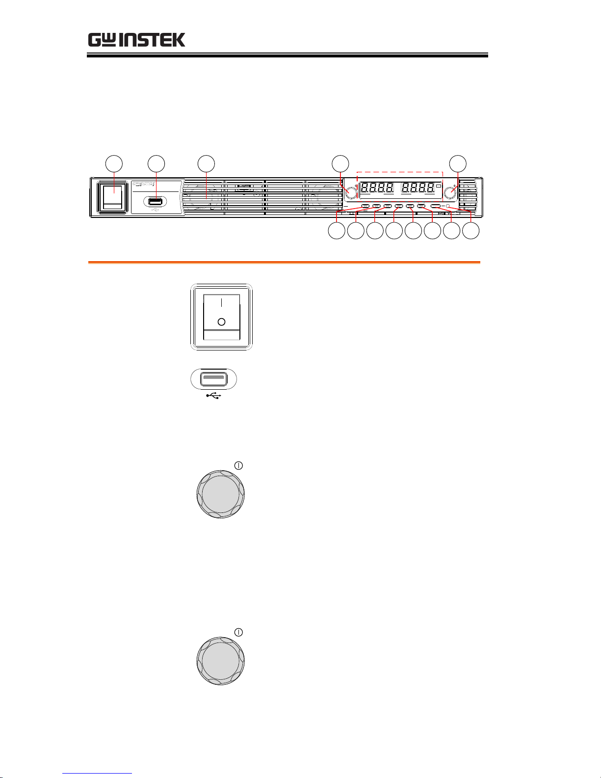
PSU Series Front Panel
Lock/Local PROT Function Test Set Output
Unlock ALM_CLR M 1 M 2 M 3
Shift
: Long Push
VSR LAN RMT ERR DLY ALM ISR M 1 M 2 M 3 RUN
C C
A
C V
V
VOLTAGE CURRENT
PSU 40- 38
DC Power Supply
0 -40V / 0 -38A
Voltage Current
2 3 4 5
Display Area
1
116 7 8 9 10 12 13
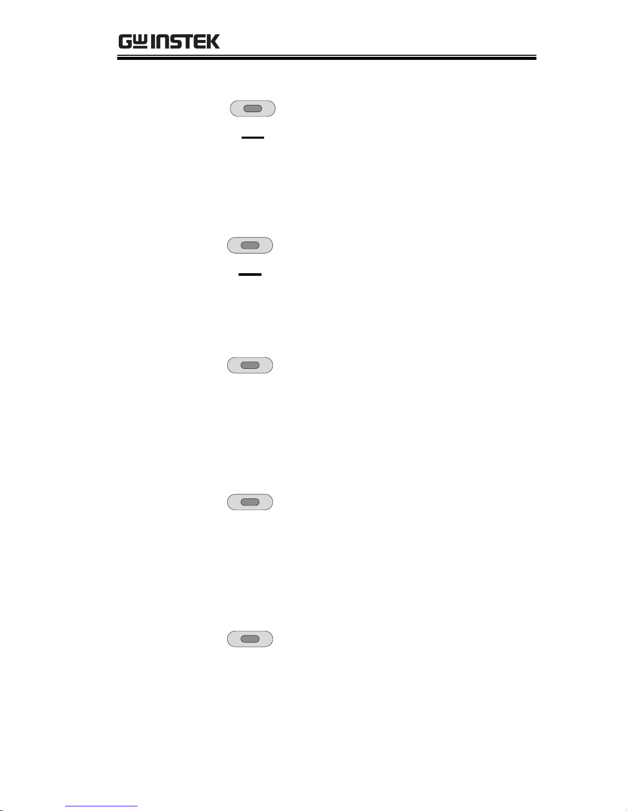
1.
Power Switch
Used to turn the power on/off.
2.
USB A Port
USB A port for data transfer,
loading test scripts etc.
3.
Air Inlet
Air inlet for cooling the inside of
the PSU series.
4.
Voltage Knob
Voltage
Used to set the voltage value or
select a parameter number in the
Function settings.
Display Area
The display area shows setting values, output
values and parameter settings. The function LEDs
below show the current status and mode of the
power supply. See page 17 for details.
5.
Current Knob
Current
Displays the current or the value
of a Function parameter.
GETTING STARTED
15
6.
Lock/Local
Button
Lock/Local
Unlock
Used to lock all front panel
buttons other than the Output
Button or it switches to local
mode.
Unlock
Button
(Long push) Used to unlock the
front panel buttons.
7.
PROT Button
PROT
ALM_CLR
Used to set and display OVP, OCP
and UVL.
ALM_CLR
Button
(Long push) Used to release
protection functions that have
been activated.
8.
Function
Button
Function
M1
Used to configure the various
function.
M1 Button
(+Shift) Used to recall the M1
setup.
(+Shift and hold) Used to save the
current setup to M1.
9.
Test Button
TEST
M2
Used to run customized scripts for
testing.
M2 Button
(+Shift) Used to recall the M2
setup.
(+Shift and hold) Used to save the
current setup to M2.
10.
Set Button
SET
M3
Used to set and confirm the output
voltage and output current.
M3 Button
(+Shift) Used to recall the M3
setup.
(+Shift and hold) Used to save the
current setup to M3.

PSU Programming Manual
16
11.
Shift Button
Shift
Used to enable the functions that
are written in blue characters
below the button.
12.
Output
Button
Output
Used to turn output on and off.
13.
Output ON
LED
Lights in green during output ON.
GETTING STARTED
17
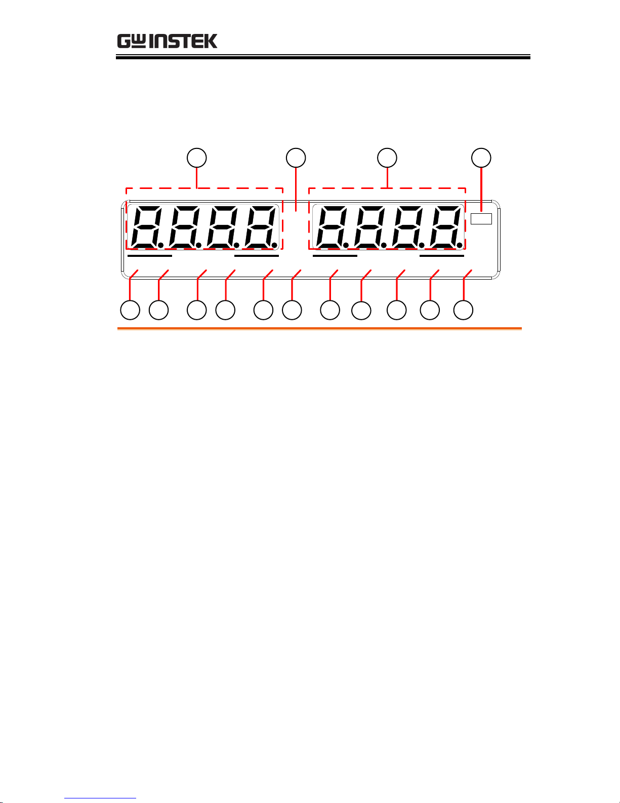
PSU Series Display and Operation Panel
VSR LAN RMT ERR DLY ALM ISR M 1 M 2 M 3 RUN
C C
A
C V
V
VOLTAGE CURRENT
Display Area
14 1516 17
18 19 20 21 22 23 24
25
26 27 28
14.
Voltage
Meter
Displays the voltage or the parameter number of a
Function parameter.
15.
Current
Meter
Displays the current or the value of a Function
parameter.
16.
CV LED
Lights in green during constant voltage mode.
17.
CC LED
Lights in green during constant current mode.
18.
VSR LED
The voltage slew rate enable.
19.
LAN LED
Lights up when the LAN interface is connected.
20.
RMT LED
Lights in green during remote control.
21.
ERR LED
Lights in red when an error has occurred.
22.
DLY LED
The output on/off delay enable.
23.
ALM LED
Lights in red when a protection function has been
activated.

PSU Programming Manual
18
24.
ISR LED
The current slew rate enable.
25.
M1 LED
Lights in green when the memory value are being
recalled or saved.
26.
M2 LED
Lights in green when the memory value are being
recalled or saved.
27.
M3 LED
Lights in green when the memory value are being
recalled or saved.
28.
RUN LED
Auto sequence has been activated.
Note
Only the ERR and ALM LED’s are red. All the
others are green.
GETTING STARTED
19
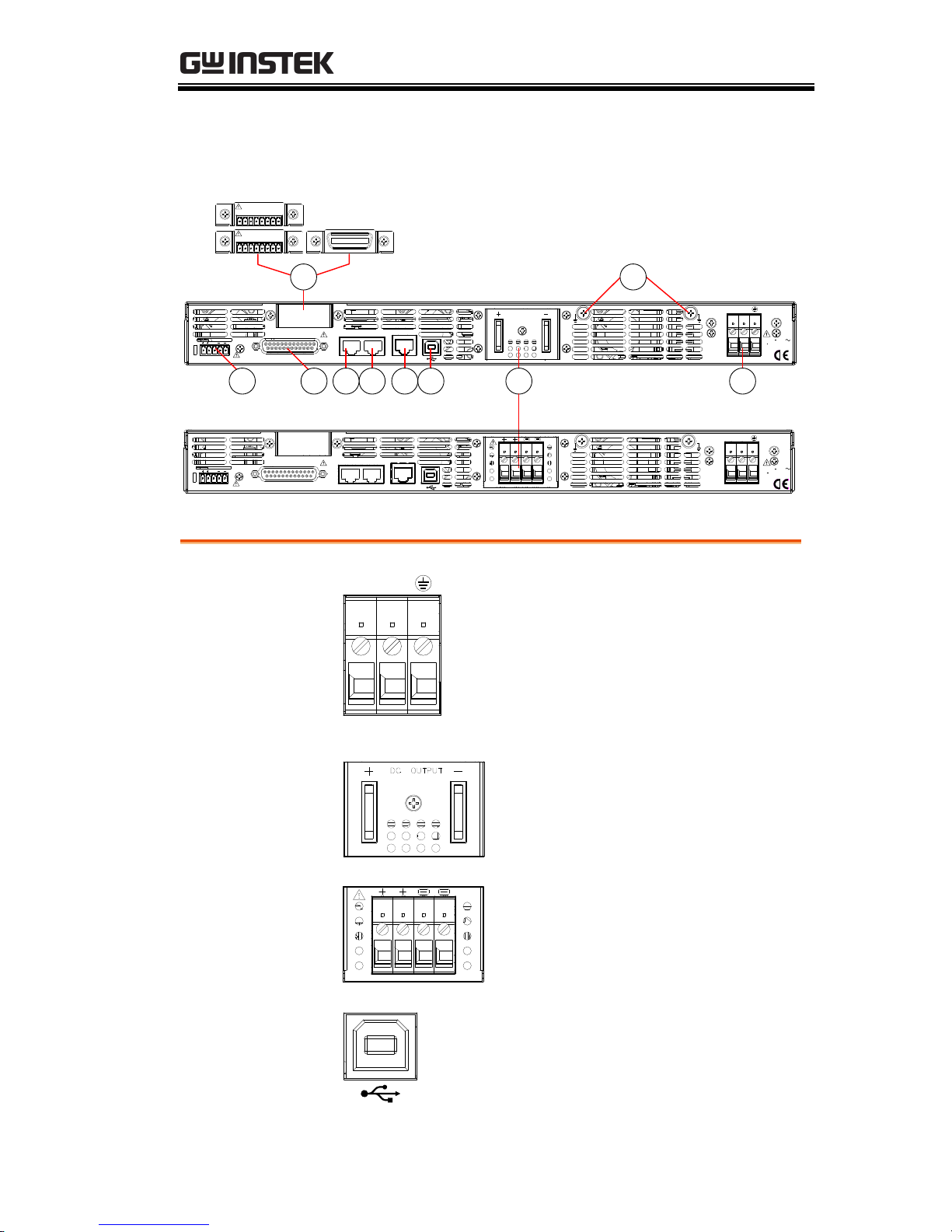
Rear Panel
S LS SLSNC
REMOTE SENSE
ANALOG PROGRAMMING
RS485 / 232
OUT IN
LAN
DC OUTPUT
AC INPUT
L N
100 240V
2000VA MAX.
AC
47 63Hz
234 15678
9 10
87654321
0 -5V / 0 - 10V
ISOLATED PROGRAMMING
87654321
4 -20mA
ISOLATED PROGRAMMING
6-60V models:
PSU 6-200, 12.5-120,
20-76, 40-38, 60-25
100-600V models:
PSU 100-15, 150-10,
300-5, 400-3.8, 600-2.6
S LS SLSNC
REMOTE SENSE
ANALOG PROGRAMMING
OUT IN
RS485 / 232
LAN
L N
AC INPUT
100 240V
2000VA MAX.
AC
47 63Hz
1.
AC Input
L N
AC INPUT
Wire clamp connector.
2.
DC Output
Output terminals for 6V to 60V
models.
Output terminals for 100V to 600V
models.
3.
USB
USB port for controlling the PSU
remotely.
PSU Programming Manual
20
4.
LAN
LAN
RS 485 / 232
Ethernet port for controlling the
PSU remotely.
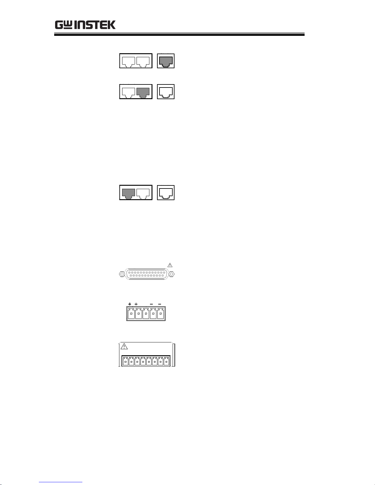
5.
Remote-IN
LAN
RS 485 / 232
Two different types of cables can
be used for RS232 or RS485-based
remote control.
PSU-232: RS232 cable with DB9
connector kit.
PSU-485: RS485 cable with DB9
connector kit.
6.
Remote-OUT
LAN
RS 485 / 232
RJ-45 connector that is used to
daisy chain power supplies with
the Remote-IN port to form a
communication bus.
PSU-485S: Serial link cable with
RJ-45 shielded connector.
7.
Analog
Control
ANALOG PROGRAMMING
External analog control connector.
8.
Remote
Sense
S LS SLSNC
Compensation of load wire drop.
9.
Option Slot
87654321
0 - 5V / 0 - 10V
ISOLATED PROGRAMMING
Blank sub-plate for standard units.
Isolated Analog connector for
units equipped with Isolated
Current and Voltage
Programming and Monitoring
option.
GPIB connector for units equipped
with IEEE programming option.
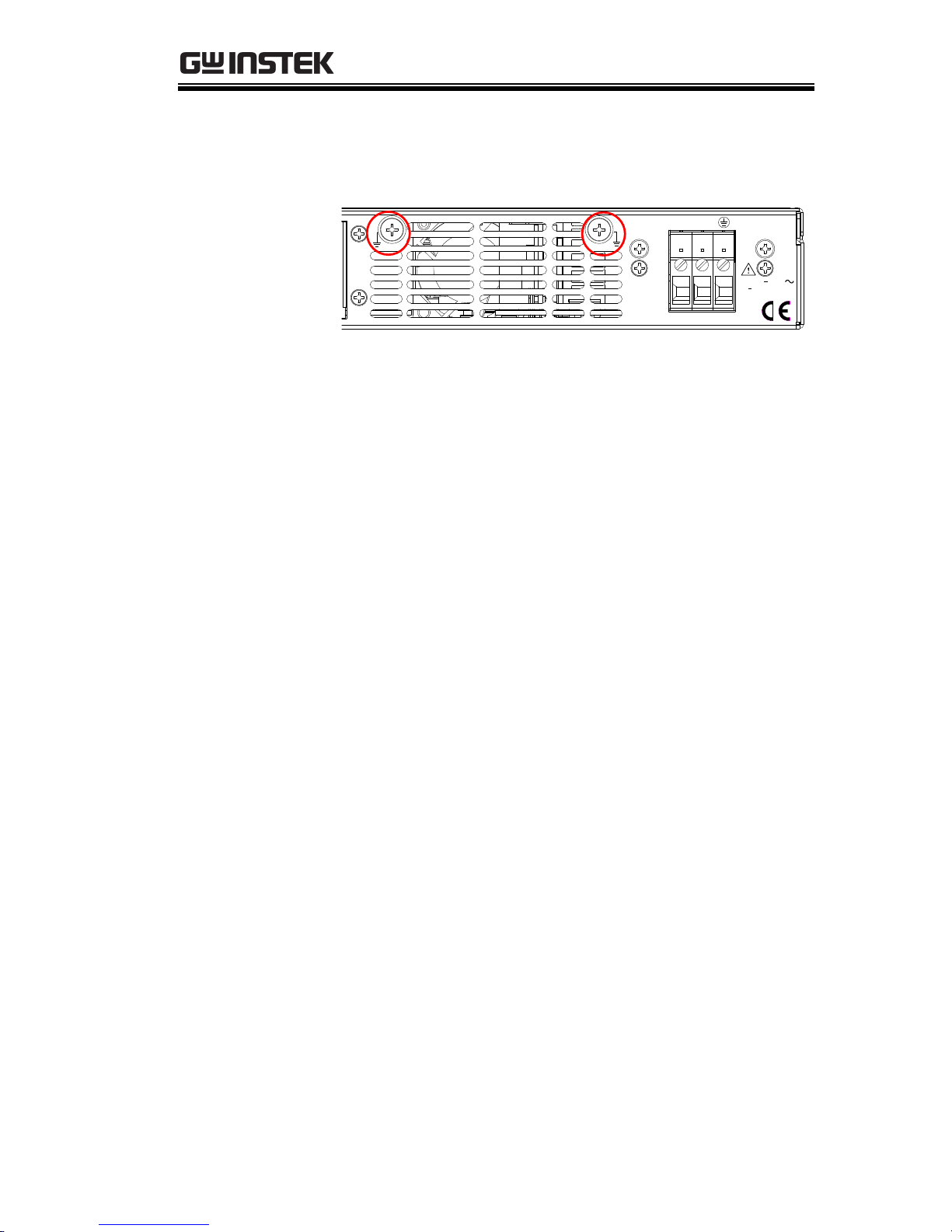
GETTING STARTED
21
10.
Ground
Screw
Connector for grounding the output (two
positions, shown in red).
L N
AC INPUT
100 240V
2000VA MAX.
AC
47 63Hz
PSU Programming Manual
22
Configuration Settings
Setting Normal Function Settings
The normal function settings, F-01~F-61, F70~F-78, F-88~F-89 and F100~F122 can be easily
configured with the Function key.
Ensure the load is not connected.
Ensure the output is off.
Function settings F-90~97 can only be
viewed.
Note
Function setting F-89 (Show Version) can only be
viewed, not edited.
Configuration settings F-90~ F-97 cannot be edited
in the Normal Function Settings. Use the Power
On Configuration Settings. See page 24 for details.
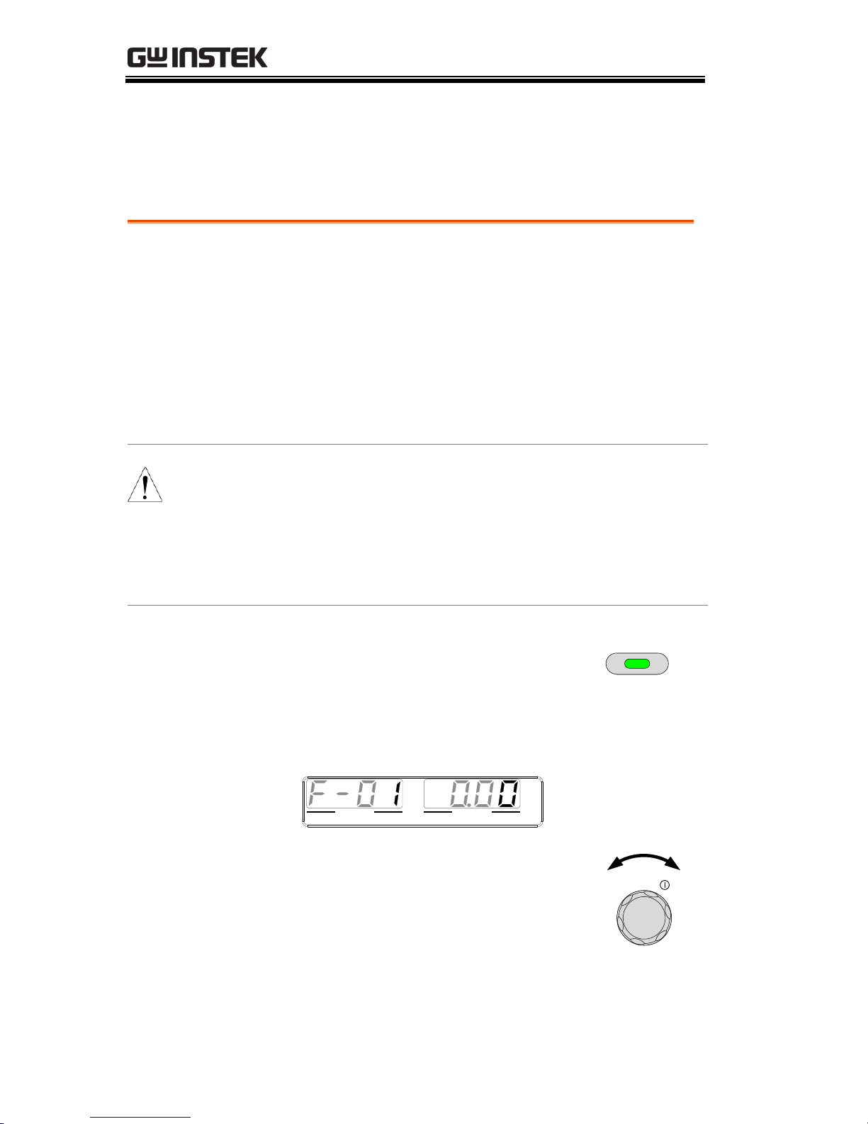
Steps
1. Press the Function key. The
function key will light up.
Function
2. The display will show F-01 on the left and the
configuration setting for F-01 on the right.
VOLTAGE CURRENT
VSR LAN RMT ERR DLY ALM ISR M 1 M 2 M 3 RUN
C V C C
V A
3. Rotate the voltage knob to change
the F setting.
Voltage
Range
F-00~F-61, F-70~F-78,
F-88~F-97, F100~F122
GETTING STARTED
23
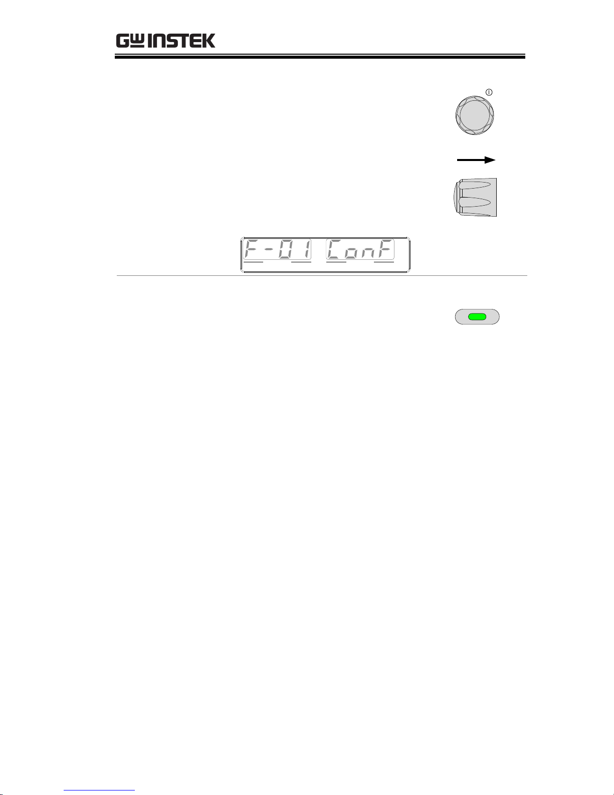
4. Use the current knob to set the
parameter for the chosen F setting.
Current
Press the Voltage knob to save the
configuration setting. ConF will be
displayed when it is configuring.
Voltage
VOLTAGE CURRENT
VSR LAN RMT ERR DLY ALM ISR M 1 M 2 M 3 RUN
C V C C
V A
Exit
Press the Function key again to exit
the configuration settings. The
function key light will turn off.
Function
PSU Programming Manual
24
Setting Power On Configuration Settings
Background
The Power On configuration settings can only
be changed during power up to prevent the
configuration settings being inadvertently
changed.
Ensure the load is not connected.
Ensure the power supply is off.
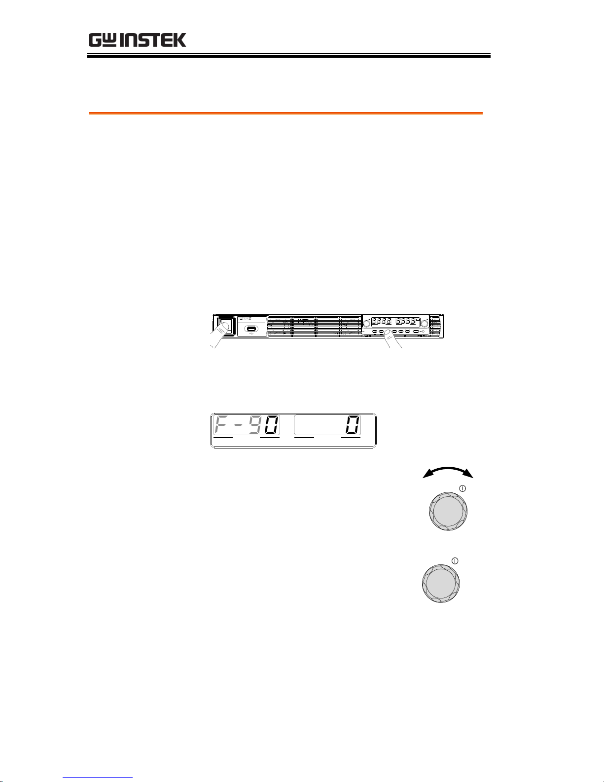
Steps
1. Hold the Function key whilst turning the
power on.
Lock/Local PROT Function Test Set
Output
Unlock ALM_CLR M 1 M 2 M 3
Shift
: Long Push
VSR LAN RMT ERR DLY ALM ISR M 1 M 2 M 3 RUN
C C
A
C V
V
VOLTAGE CURRENT
PSU 40-38
DC Power Supply
0 - 40V / 0 - 38A
Voltage Current
2. The display will show F-90 on the left and the
configuration setting for F-90 on the right.
VOLTAGE CURRENT
VSR LAN RMT ERR DLY ALM ISR M 1 M 2 M 3 RUN
C V C C
V A
3. Rotate the voltage knob to change
the F setting.
Voltage
Range
F-90 ~ F-97
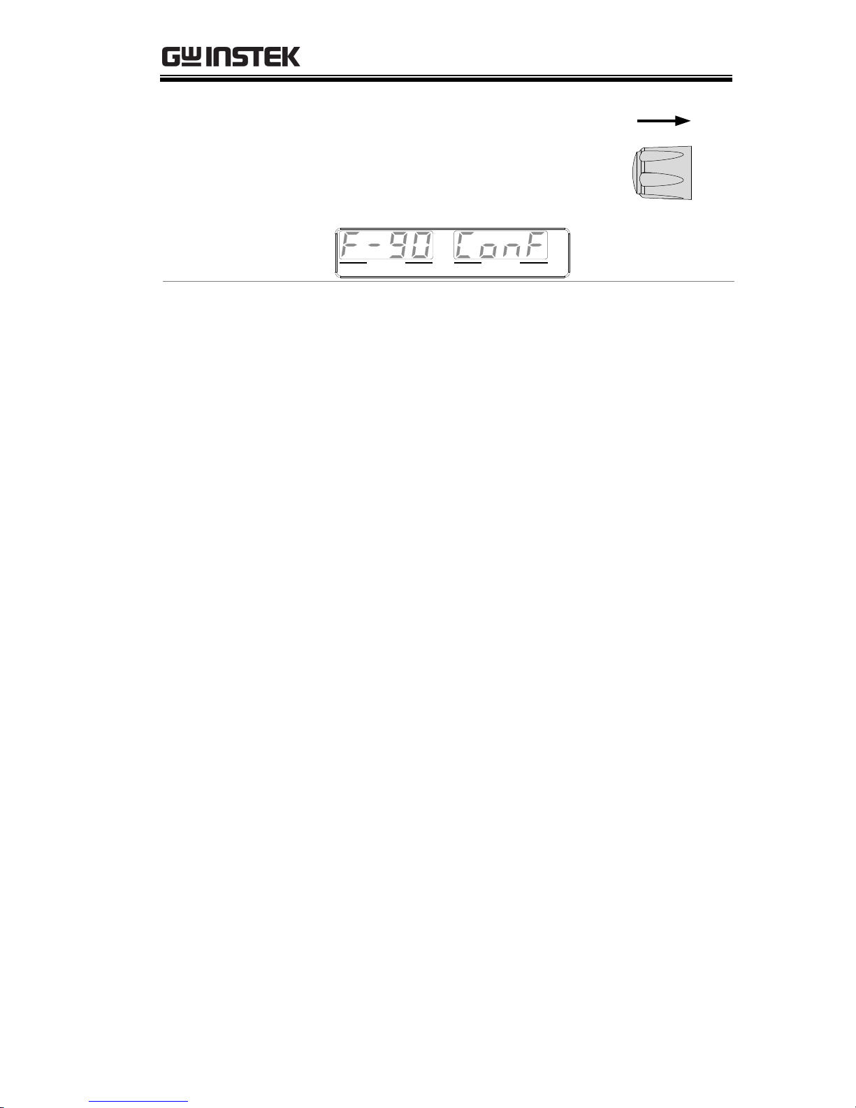
4. Use the current knob to set the
parameter for the chosen F setting.
Current
GETTING STARTED
25
Press the Voltage knob to save the
configuration setting. ConF will be
displayed when it is configuring.
Voltage
VOLTAGE CURRENT
VSR LAN RMT ERR DLY ALM ISR M 1 M 2 M 3 RUN
C V C C
V A
Exit
Cycle the power to save and exit the
configuration settings.
PSU Programming Manual
26
Configuration Table
Please use the configuration settings listed below when applying
the configuration settings.
Normal Function
Settings
Setting
Setting Range
Output ON delay time
F-01
0.00s~99.99s
Output OFF delay time
F-02
0.00s~99.99s
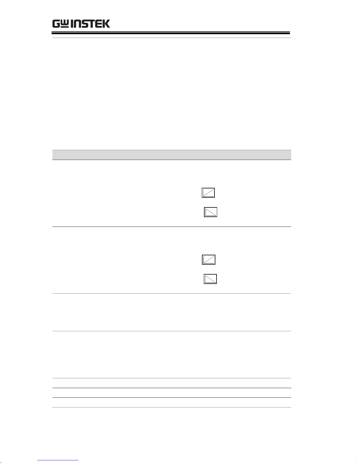
V-I mode slew rate select
F-03
0 = CV high speed priority (CVHS)
1 = CC high speed priority (CCHS)
2 = CV slew rate priority (CVLS)
3 = CC slew rate priority (CVLS)
Rising voltage slew rate
F-04
0.001~0.06V/msec (PSU 6-200)
0.001~0.125V/msec (PSU 12.5-120)
0.001~0.2V/msec (PSU 20-76)
0.001~0.4V/msec (PSU 40-38)
0.001~0.6V/msec (PSU 60-25)
0.001~1.000V/msec (PSU 100-15)
0.001~1.500V/msec (PSU 150-10)
0.001~1.500V/msec (PSU 300-5)
0.001~2.000V/msec (PSU 400-3.8)
0.001~2.400V/msec (PSU 600-2.6)
Falling voltage slew rate
F-05
0.001~0.06V/msec (PSU 6-200)
0.001~0.125V/msec (PSU 12.5-120)
0.001~0.2V/msec (PSU 20-76)
0.001~0.4V/msec (PSU 40-38)
0.001~0.6V/msec (PSU 60-25)
0.001~1.000V/msec (PSU 100-15)
0.001~1.500V/msec (PSU 150-10)
0.001~1.500V/msec (PSU 300-5)
0.001~2.000V/msec (PSU 400-3.8)
0.001~2.400V/msec (PSU 600-2.6)

GETTING STARTED
27
Rising current slew rate
F-06
0.001~2A/msec (PSU 6-200)
0.001~1.2A/msec (PSU 12.5-120)
0.001~0.76A/msec (PSU 20-76)
0.001~0.38A/msec (PSU 40-38)
0.001~0.25A/msec (PSU 60-25)
0.001~0.150A/msec (PSU 100-15)
0.001~0.100A/msec (PSU 150-10)
0.001~0.025A/msec (PSU 300-5)
0.001~0.008A/msec (PSU 400-3.8)
0.001~0.006A/msec (PSU 600-2.6)
Falling current slew rate
F-07
0.001~2A/msec (PSU 6-200)
0.001~1.2A/msec (PSU 12.5-120)
0.001~0.76A/msec (PSU 20-76)
0.001~0.38A/msec (PSU 40-38)
0.001~0.25A/msec (PSU 60-25)
0.001~0.150A/msec (PSU 100-15)
0.001~0.100A/msec (PSU 150-10)
0.001~0.025A/msec (PSU 300-5)
0.001~0.008A/msec (PSU 400-3.8)
0.001~0.006A/msec (PSU 600-2.6)
Internal resistance
setting
F-08
0~0.03Ω (PSU 6-200)
0~0.104Ω (PSU 12.5-120)
0~0.263Ω (PSU 20-76)
0~1.053Ω (PSU 40-38)
0~2.4Ω (PSU 60-25)
0~6.667Ω (PSU 100-15)
0~15.00Ω (PSU 150-10)
0~60.00Ω (PSU 300-5)
0~105.3Ω (PSU 400-3.8)
0~230.8Ω (PSU 600-2.6)
Bleeder circuit control
F-09
0 = OFF, 1 = ON, 2 = AUTO
Buzzer ON/OFF control
F-10
0 = OFF, 1 = ON
OCP Delay Time
F-12
0.1 ~ 2.0 sec
Current Setting Limit
(I-Limit)
F-13
0 = OFF, 1 = ON
Voltage Setting Limit
(V-Limit)
F-14
0 = OFF, 1 = ON
PSU Programming Manual
28
Display memory
parameter when recalling
(M1, M2, M3)
F-15
0 = OFF, 1 = ON
Auto Calibration Parallel
Control
F-16
0 = Disable, 1 = Enable, 2 = Execute
Parallel Calibration and set to Enable.
Note: Must be a short between each
unit before starting.
Measurement Average
Setting
F-17
0 = Low, 1 = Middle, 2 = High
Alarm Recovery and
Output Status
F-18
0 = Safe Mode, 1 = Force Mode
Lock Mode
F-19
0:Lock Panel, Allow Output OFF
1:Lock Panel, Allow Output ON/OFF
USB/GPIB settings
Show front panel USB
status
F-20
0 = None, 1 = Mass Storage
Show rear panel USB
status
F-21
0 = None, 1 = Linking to PC
Setup rear USB Speed
F-22
0 = Disable USB, 1 = Full Speed, 2 =
Auto Detect Speed
GPIB Address
F-23
0 ~ 30
GPIB Enable/Disable
F-24
0 = Disable GPIB, 1 = Enable GPIB
Show GPIB available
status
F-25
0 = No GPIB, 1 = GPIB is available
SCPI Emulation
F-26
0 = GW Instek, 1 = TDK GEN, 2 =
Agilent 5700, 3 = Kikusui PWX
LAN settings
Show MAC Address-1
F-30
0x00~0xFF
Show MAC Address-2
F-31
0x00~0xFF
Show MAC Address-3
F-32
0x00~0xFF
Show MAC Address-4
F-33
0x00~0xFF
Show MAC Address-5
F-34
0x00~0xFF
Show MAC Address-6
F-35
0x00~0xFF
LAN Enable
F-36
0 = OFF, 1 = ON
DHCP
F-37
0 = OFF, 1 = ON
IP Address-1
F-39
0~255
IP Address-2
F-40
0~255
IP Address-3
F-41
0~255
IP Address-4
F-42
0~255
Subnet Mask-1
F-43
0~255
GETTING STARTED
29
Subnet Mask-2
F-44
0~255
Subnet Mask-3
F-45
0~255
Subnet Mask-4
F-46
0~255
Gateway-1
F-47
0~255
Gateway-2
F-48
0~255
Gateway-3
F-49
0~255
Gateway-4
F-50
0~255
DNS address -1
F-51
0~255
DNS address -2
F-52
0~255
DNS address-3
F-53
0~255
DNS address-4
F-54
0~255
Socket Server
Enable/Disable
F-57
0 = Disable, 1 = Enable
Show Socket Server Port
F-58
No setting
Web Server
Enable/Disable
F-59
0 = Disable, 1 = Enable
Web Password
Enable/Disable
F-60
0 = Disable, 1 = Enable
Web Enter Password
F-61
0000~9999
UART Settings
UART Mode
F-70
0 = Disable UART, 1 = RS232,
2 = RS485
UART Baud Rate
F-71
0 = 1200, 1 = 2400, 2 = 4800,
3 = 9600, 4 = 19200, 5 = 38400,
6 = 57600, 7 = 115200
UART Data Bits
F-72
0 = 7 bits, 1 = 8 bits
UART Parity
F-73
0 = None, 1 = Odd, 2 = Even
UART Stop Bit
F-74
0 = 1 Bit, 1 = 2 Bits
UART TCP
F-75
0 = SCPI, 1 = TDK (emulation mode)
UART Address
(For multi-unit remote
control)
F-76
00 ~ 30
UART Multi-Drop control
F-77
0 = Disable, 1 = Master, 2 = Slave,
3 = Display information
UART Multi-Drop status
F-78
Displayed parameter: AA-S
AA: 00~30 (Address),
S: 0~1 (Off-line/On-line status).
System Settings
Factory Set Value
F-88
0 = None
1 = Return to factory default settings
PSU Programming Manual
30
Show Version
F-89
0, 1 = Version
2, 3, 4, 5 = Build date (YYYYMMDD)
6, 7 = Keyboard CPLD
8, 9 = Analog Board CPLD
A, B = Analog Board FPGA
C, D, E, F = Kernel Build
(YYYYMMDD)
G, H = Test Command Version
I, J, K, L = Test Command Build
(YYYYMMDD)
M, N = Reserved
O, P = Option Module
Power On Configuration Settings*
CV Control
F-90
0 = Control by Local
1 = Control by External Voltage
2 = Control by External Resistor -
Rising
3 = Control by External Resistor -
Falling
4 = Control by Isolated Board
CC Control
F-91
0 = Control by Local
1 = Control by External Voltage
2 = Control by External Resistor -
Rising
3 = Control by External Resistor -
Falling
4 = Control by Isolated Board
Output Status when
Power ON
F-92
0 = Safe Mode (Always OFF),
1 = Force Mode (Always ON),
2 = Auto Mode (Status before last
time power OFF)
Master/Slave
Configuration
F-93
0 = Independent
1 = Master with 1 slave in parallel
2 = Master with 2 slaves in parallel
3 = Master with 3 slaves in parallel
4 = Slave (parallel)
External Output Logic
F-94
0 = High ON, 1 = Low ON
Monitor Voltage Select
F-96
0 = 5V , 1 = 10V
Control Range
F-97
0 = 5V [5kΩ], 1 = 10V [10kΩ]
 Loading...