

Page 1

PST & PSS & PSH SERIES PROGRAMMABLE POWER SUPPLY
PST & PSS & PSH SERIES PROGRAMMABLE POWER SUPPLY
PROGRAMMER MANUAL
CONTENTS PAGE
1. INTRODUCTION............................ ........... ........... ........... ........ ........
2. CONNECTING POWER SUPPLY VIA G PIB INTERFACE..
1
1
3. CONNECTING POWER SUPPLY VIA RS232 INTERFACE 4
4.
INPUT AND OUTPUT QUEUE………………………………..
7
5. COMMANDS AND SYNTAX…………………………………. 7
6. DETAILS OF COMMAND REFERENCE…………………… 19
7. STATUS AND ERROR REPORTING………………………....
38
PROGRAMMER MANUAL
⎯ i ⎯
⎯ ii ⎯
Page 2

PST & PSS & PSH SERIES PROGRAMMABLE POWER SUPPLY
PST & PSS & PSH SERIES PROGRAMMABLE POWER SUPPLY
PROGRAMMER MANUAL
1. INTRODUCTION
In the modern automatic measurement system, communication
between equipments and computers is essential. The measured
procedures can be varied with users’ testing programs, therefore, the
programmable power supply can be operated remotely from an
instrument controller or computer across the RS232 interface (optional)
or GPIB (optional).
Interface selection and setup
The GPIB address can be changed in normal op eration condition. Press
[SHIFT] key and [LOCAL] key on the front panel, in which the last
transmitting interface settings will be displayed. Select interface and
press [ENTER], then select the baud rate (or GPIB address) and press
[ENTER] to confirm the setting by using the knobs. Finally, select “save”
and press [ENTER] to store the setup.
2. CONNECTING THE PROGRAMMABLE POWER
SUPPLY VIA GPIB INTERFACE
PROGRAMMER MANUAL
L4 (Listener) : The power supply becomes a listener
when the controller sends its listen
address with the ATN (attention) line
asserted. The power supply does not
have listen only capability.
SR1 (Service Request) : The power su pply asserts the SRQ
(Service request) line to notify the
controller when it requires service.
RL1 (Remote/Local) : The power supply responds to both the
GTL(Go to Local) and LLO(Local Lock
Out) interface messages.
PP0 (Parallel Poll) : The power supply has no Parallel Poll
interface function.
DC1 (Device Clear) : The power supply has Device clear
capability to return the device to power
on status.
DT0 (Device Trigger) : The power supply has no Device Trigger
interface function.
C0 (Controller) : The power supply can not control other
devices.
The GPIB interface capabilities:
The GPIB interface of the programmable power supply correspond s to
the standard of IEEE488.1-1987, IEEE488.2-1992 and SCPI-1994. The
GPIB interface functions are listed as follows:
SH1(Source Handshake) : The power supply can transmit multilane
messages across the GPIB.
AH1(Acceptor Handshake) : The power supply can receive multilane
messages across the GPIB.
T6(Talker) : Talker interface function includes basic
talker, serial poll, and unaddress if MLA
capabilities, without talk only mode
function.
⎯ 1 ⎯
Notes for GPIB installation
When the programmable power supply is set up with a GPIB system,
please check the following things:
z Only a maximum of 15 devices can be connected to a single GPIB
bus.
z Do not use more than 20m of cable to connect devices to a bus.
z Connect one device for every 2m of cable used.
z Each device on the bus needs a unique device address. No two
devices can share the same device address.
⎯ 2 ⎯
Page 3

PST & PSS & PSH SERIES PROGRAMMABLE POWER SUPPLY
PST & PSS & PSH SERIES PROGRAMMABLE POWER SUPPLY
PROGRAMMER MANUAL
z Turn on at least two-thirds of the devices on the GPIB system while
using the system .
z Do not use loop or parallel structure for the topology of GPIB
system.
Computer’s Connection
A personal computer with a GPIB card is the essential facilities in order
to operate the programmable power supply via GPIB interface.
The connections between power supply and computer are following:
I. Connect one end of a GPIB cable to the computer.
II. Connect the other end of the GPIB cable to the G PIB port on
the programmable power supply.
III. Turn on the programmable power supply.
IV. Turn on the computer.
The GPIB connection testing
If you want to test whether the GPIB connection is working or not, you
can send a GPIB command from computer. For instance, the query
command
*idn?
should return the Manufacturer, model number, serial number and
firmware version in the following format:
WK.TMPRO,PST-3202,A000000,FW1.00
If you do not receive a proper response from the power supply, please
check if the power is on, the GPIB address is correct, and all cable
connections are active.
PROGRAMMER MANUAL
3. CONNECTING THE PROGRAMMABLE POWER
SUPPLY VIA RS232 INTERFACE
The RS232 interface capabilit ies:
The RS232 interface provides a point-to-point conn ection between two
items of equipment such as a computer and the power supply. There are
some parameters you need to set on the both sides. Once you have set
these parameters, you can control the power supply through the RS232
interface.
z Baud rate: You can set rates of 1200, 2400, 4800 or 9600 b aud.
z Parity bit: none.
z Data bit: 8 bits.
z Stop bit: 1 stop bit.
z Data flow control: none.
Notes for RS232 installation
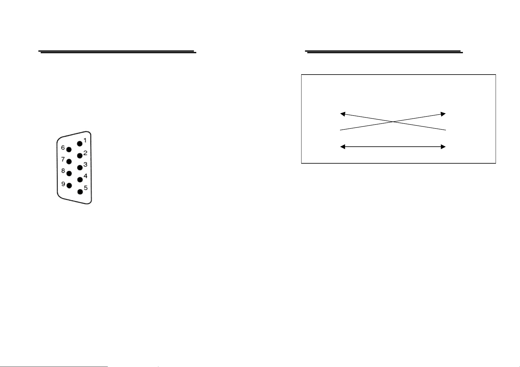
The power supply is a DTE device with a 9-pin D-type shell RS232
connector located on the rear panel. Figure 1 shows the equipment of 9pin connector (male) with its pin number assignments. Figure 2 shows
the wiring configuration for DB9 to DB9. When the p rogra mmab le pow er
supply is set up with a RS232 interface, please check the following
points:
z Do not connect the output line of one DTE device to the output line
of the other.
z Many devices require a constant high signal on one or more input
pins.
z Ensure that the signal ground of the equipment is connected to the
signal ground of the external device.
z Ensure that the chassis ground of the equipment is connected to the
chassis ground of the external device.
⎯ 3 ⎯
⎯ 4 ⎯
Page 4
PST & PSS & PSH SERIES PROGRAMMABLE POWER SUPPLY
PST & PSS & PSH SERIES PROGRAMMABLE POWER SUPPLY
PROGRAMMER MANUAL
z Do not use more than 15m of cable to connect devices to a PC.
z Ensure the same baud rate is used on the dev ice as the one used on
PC terminal.
z Ensure the connector for the both side of cable and the internal
connected line are met the demand of the instrumen t.
1. No connection
2. Receive Data (RxD) (input)
3. Transmit Data (TxD) (ou tput)
4. No connection
5. Signal Ground (GND)
6. No connection
7. No connection
8. No connection
9. No connection
Figure 1 Pin assignments of the RS232 connector on the rear panel for DB-9-D
PROGRAMMER MANUAL
EQUIPMENT
(DB9, DTE)
Pin2
Pin3
COMPUTER
(DB9, DTE)
Pin2
Pin3
Pin5 Pin5
Figure 2 Wiring configuration for DB9 to DB9
Computer’s Connection
A personal computer with a COM port is the essential facilities in order
to operate the programmable power supply via RS232 inter face.
The connections between power supply and computer are as follows:
⎯ 5 ⎯
I. Connect one end of a RS232 cable to the computer.
II. Connect the other end of the cable to the RS232 port on the
programmable power supply.
III. Turn on th e progr ammab le power supply.
IV. Turn on the computer.
⎯ 6 ⎯
Page 5

PST & PSS & PSH SERIES PROGRAMMABLE POWER SUPPLY
PST & PSS & PSH SERIES PROGRAMMABLE POWER SUPPLY
PROGRAMMER MANUAL
The RS232 connection testin g
If you want to test whether the RS232 connection is working o r not, you
can send a command from computer. For instance, using a terminal
program send the query command
*idn?
should return the Manufacturer, model number, serial number and
firmware version in the following format:
WK.TMPRO,PST-3202,A000000,FW1.00
If you do not receive a proper response from the power supply, please
check if the power is on, the RS232 baud rate are th e same on both sides,
and all cable connections are activ e.
4. INPUT AND OUTPUT QUEUE
The design of 128 bytes input queue and 128 bytes output queue for
storing the pending commands or return messages is to prevent the
transmitted commands of remote control and return messages from
missing. As the maximum stored capacity for Error/Event Queue is 20
groups of messages, it should be noted that input data exceeding the
capacity by using these buffers will cause data missing.
5. COMMANDS AND SYNTAX
The GPIB commands of the programmable power supply are
compatible with IEEE-488.2 and SCPI standards
SCPI
SCPI (Standard Commands for Programmable Instruments) is a standard
that created by an international consortium of the major test and
measurement equipment manufacturers. The IEEE-488.2
adopted by SCPI to provide common commands for the identical
functions of different programmable instruments.
syntax has been
PROGRAMMER MANUAL
SCPI
Common Command & Queries
Syntax & Status Data Structure
Interface Function
AABBCCDD
SCPI
IEEE-488.2 IEEE-488.2
Figure 3 the relationship between IEEE-488.1, IEEE-488.2, and SCPI
SCPIIEEE-488.1
As shown in the figure 3, the IEEE-488.1 standard locates at layer A, the
layer A belongs to the protocol of interface function on the GPIB bus.
The source handshake (SH), acceptor handshake (AH) and talker are
included to this l ayer (10 int erf ace fun ctio ns to tall y).
At layer B, the syntax and data structure could be the e ssence of entire
IEEE-488.2 standard. The syntax defines the function of message
communication, which contain the <PROGRAM MESSAGE> (or simply
“commands”) and <RESPONSE MESSAGE>. The two kinds of messages
represent the syntax formation of device command and return value. The
data structure is the constitution of status reporting, which IEEE-488.2
standard have been defined.
The common commands and q ueries are included to layer C. Commands
and queries can be divided into two parts: mandatory and optional.
Commands modify control settings or tell the instrument to perform a
specific action. Queries cause the instrument to send data or status
information back to the computer. A question mark at the end of a
⎯ 7 ⎯
⎯ 8 ⎯
Page 6
PST & PSS & PSH SERIES PROGRAMMABLE POWER SUPPLY
PST & PSS & PSH SERIES PROGRAMMABLE POWER SUPPLY
PROGRAMMER MANUAL
command identifies it as a query.
Layer D is interrelated with device information. Different devices have
different functions. SCPI command sets belong to this layer.
Command Syntax
If you want to transfer any instructions to an instrument, and comply
with SCPI, there are three basic elements must be included.
z Command header
z Parameter (if required)
z Message terminator or separator
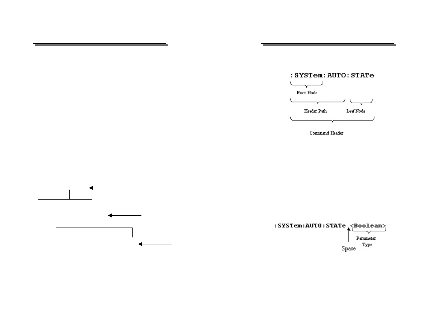
Command Header
The command header has a hierarc hical structure tha t can be represented
by a command tree (Figure 4).
The top level of the tree is the root level. A root node is located at the
root level. A root node and one or more lower-level nodes form a header
path to the last node called the leaf node.
Root node
PROGRAMMER MANUAL
The command header is configured by header path and leaf node. Figure 5
shows the command header for the leaf node indicated in Figure 4.
Figure 5 Command Header
Parameter
If the commands have parameters, the values have to be included. In this
manual, when we expressed th e syntax of the co mmand, the < > s ymbols
are used for enclosing the par ameter type . For instance, the syntax of the
command in Figure 6 includes the Boolean parameter type.
Figure 4: Tree hierarchy
⎯ 9 ⎯
Lower-level node
Leaf Node
NOTE: Do not include the <, >, or | symbols when entering the actual
value for a parameter.
Figure 6 Command Header with Parameter
⎯ 10 ⎯
Page 7

PST & PSS & PSH SERIES PROGRAMMABLE POWER SUPPLY
PST & PSS & PSH SERIES PROGRAMMABLE POWER SUPPLY
PROGRAMMER MANUAL
Table 1 defines the Boolean and other parameter types for the
programmable power supply.
Parameter Type Description Example
Boolean Boolean numbers or
0, 1
values
NR1 Integers 0, 1, 18
NR2 Decimal numbers 1.5, 3.141, 8.4
NR3 Floating point numbers 4.5E-1, 8.25E+1
String Alphanumeric characters “No error”
Table 1: Parameter Type s for Sy ntax Descript ions
Message Terminator and Message Separator
I. GPIB message terminators
In accordance with IEEE 488.2 standard, any of the following message
terminators are acceptable:
^
z LF
END Line feed code (hexade ci mal 0A ) with END
message
z LF Line feed code
z <dab>
^
END Last data byte with END message
These terminators are compatible with most application programs. A
semicolon separates one co mmand from another when the commands
appear on the same line.
PROGRAMMER MANUAL
II. RS232 message terminators
As there is no signal of end message on RS232 bus, therefore, use LF
as message terminator. When a series of commands are sent to the
instrument, it must add a LF to be a judgment for message terminator.
As for query command, the return message of the instrument is also
added a LF for PC to judge message terminator.
Entering Commands
The standards that govern the command set for the programmable power
supply allow for a certain amount of flexibility when you enter
commands. For instance, you can abbreviate many commands or
combine commands into one message that you send to the programmable
power supply. This flexibility, called friendly listening, saves
programming time and makes the command set easier to remember and
use.
Command Characters
The programmable power supplies are not sensitive to the case of
command characters. You can enter commands in either uppercase or
lowercase.
You can execute any command with white space characters. You must,
however, use at least one space between the parameter and the command
header
Abbreviating Commands
Most commands have a long form and a short form. The listing for
each command in this section shows the abbreviations in uppercase.
For instance, you can enter the query :CHANnel1:VOLTage 1.23
simply as :CHAN1:VOLT 1.23
⎯ 11 ⎯
⎯ 12 ⎯
Page 8

PST & PSS & PSH SERIES PROGRAMMABLE POWER SUPPLY
PST & PSS & PSH SERIES PROGRAMMABLE POWER SUPPLY
PROGRAMMER MANUAL
Because the programmable power supply hypothesis that a command
starts from the root, you have the option of beginning the initial
command header with a colon (:).
Combining Commands
You can use a semicolon (;) to combine commands. But continuously
query command will cause message missing. For example:
CHAN1:VOLT ?;CURR ?
If the command that follows the semicolon has a different header path
from the root level, you must use a colon to force a return to the root
level:
:CHAN1:VOLT 1.23;:OUTP:COUP:TRAC 1
If the command that follows the semicolon has the same header path, you
may omit the colon and the path and state only the new leaf node. For
example:
:CHAN1:VOLT 12.34;CHAN1:CURR 1.55
is equal to
:CHAN1:VOLT 12.34;CURR 1.55
You can combine commands and queries into the same message. Note,
for example, the following comb ination :
:CHAN1:VOLT 12.34;VOLT ?
PROGRAMMER MANUAL
z
General Setting Commands
Table 2 lists the general setting commands that control and query the
settings of the power supply.
Table 2: General Setting Commands
Command Explanation
:CHANnel<x>:CURRent <NR2> ★1 Sets the value of current.
:CHANnel<x>:CURRent ? ★1 Return the value of current.
:CHANnel<x>:VOLTage <NR2> ★1 Sets the value of voltage.
:CHANnel<x>:VOLTage ? ★1 Return the value of voltage.
:CHANnel<x>:MEASure:CURRent ? ★1 Returns actual output current.
:CHANnel<x>:MEASure:VOLTage ? ★1 Returns actual output voltage.
:CHANnel<x>:PROTection:CURRent
<Boolean>
:CHANnel<x>:PROTection:CURRent ? ★1 Returns the state of the over-
:CHANnel<x>:PROTection:VOLTage
<NR2>
★1 Sets the overcurrent protection
(OCP) on or off.
current protection (OCP)
setting as either on or off.
★1 Sets the value of overvoltage
protection (OVP).
Synopsis of Commands
The tables in this section summarize the command of the programmable
power supply. These tables divide the commands into three functional
classifications:
z General Setting Commands
z Status Commands
z Miscellaneous Commands
The tables also provide a brief explanation of each command.
⎯ 13 ⎯
:CHANnel<x>:PROTection:VOLTage ? ★1 Returns the overvoltage
protection (OVP) setting.
:OUTPut:COUPle:TRACking <NR1> ★2 Sets the output of the power
supply working on Seriestracking or Parallel-tracking or
independent mode.
:OUTPut:COUPle:TRACking ? ★2 Returns the output of the power
supply working mode.
⎯ 14 ⎯
Page 9

PST & PSS & PSH SERIES PROGRAMMABLE POWER SUPPLY
PST & PSS & PSH SERIES PROGRAMMABLE POWER SUPPLY
PROGRAMMER MANUAL
:OUTPut:PROTection:CLEar Clears over-voltage and over-current and
over temperature protection error message.
:OUTPut:STATe <Boolean> Sets the output state on or off.
:OUTPut:STATe ? Returns the output state on or off.
Remark:
The mark “★1” means the <X> for PSS and PSH series can only be 1.
The mark “★2” means the PSS and PSH series do not have the function.
z Status Commands
Table 3 lists the status commands that set and query the various
registers and queues that make up the status and event structure of the
programmable power supply.
Table 3: Status Commands
*CLS Clears the status data structures.
*ESE <NR1> Sets the Event Status Enable Register
(ESER).
*ESE? Returns contents of Event Status Enable
Register (ESER).
PROGRAMMER MANUAL
*SRE? Returns contents of Service Request
Enable Register (SRER).
*STB? Reads Status Byte Register (SBR).
:STATus:OPERation:COND
ition ?
:STATus:OPERation:ENAB
le <NR1>
:STATus:OPERation:ENAB
le ?
:STATus:OPERation:EVEN
t ?
Returns the contents of the OPERation
condition register. Returns NR1.
Sets the contents of the enable mask for the
OPERation event register.
Returns the contents of the enable mask for
the OPERation event register. Returns NR1.
Query the contents of the OPERation Event
register.
:STATus:PRESet Presets the OPERation and QUEStionable
status registers.
:STATus:QUEStionable:CO
NDition ?
:STATus:QUEStionable:EN
ABle <NR1>
:STATus:QUEStionable:EN
ABle ?
:STATus:QUEStionable:EV
ENt ?
Returns the contents of the OPERation
condition register. Returns NR1.
Sets the contents of the enable mask for the
QUEStionable enable re giste r.
Query the contents of the Questionable
Enable register.
Query the contents of the QUEStionable
Event register.
z Miscellaneous Commands
*ESR? Returns and clear the contents of Standard
Event Status Register (SESR).
*SRE <NR1> Sets contents of Service Request Enable
Register(SRER).
⎯ 15 ⎯
Table 4 lists the miscellaneous commands that control general
housekeeping functions of the programmable power supply.
⎯ 16 ⎯
Page 10

PST & PSS & PSH SERIES PROGRAMMABLE POWER SUPPLY
PST & PSS & PSH SERIES PROGRAMMABLE POWER SUPPLY
PROGRAMMER MANUAL
Table 4: Miscellaneous Commands
*IDN? Returns instrument identification.
*OPC Reports when operation is complete by setting
the Operation Complete bit in SESR.
*OPC? Reports when operation is complete. Same as
*OPC except returns a 1 to the output queue
and dose not set the SESR bit.
*RCL ★Recall the setting data from the memory
which previous saved.
*RST Resets the protection levels and states, resets
the current and voltage levels to zero, sets the
output off, and sets memory section to 00.
*SAV ★Saves the setting data to memory.
*TST? Initiates internal self-test and reports results.
*WAI Wait to continue. This command forces
sequential operation of commands. This
command is required by IEEE-488.1-1987.
The power supply, however, forces sequential
operation of commands by design.
:SYSTem:AUTO:CYCLe
★Set number of times of execution.
<NR1>
:SYSTem:AUTO:CYCLe ? ★Query the setting of the number of times of
execution.
PROGRAMMER MANUAL
:SYSTem:AUTO:DELay
<NR1>
★ Set the delay time under the current
responding memory status.
:SYSTem:AUTO:DELay ? ★Query the setting of the delay time under
the current responding memory status.
:SYSTem:AUTO:END
<NR1>
★ Set the end memory section for auto
execute continuously.
:SYSTem:AUTO:END ? ★Query the end memory section for auto
execute continuously.
:SYSTem:AUTO:STARt
<NR1>
★ Set the start memory section for auto
execute continuously.
:SYSTem:AUTO:STARt ? ★Query the start memory section for auto
execute continuously.
:SYSTem:AUTO:STATe
★Sets Auto sequence on or off.
<Boolean>
:SYSTem:AUTO:STATe ? ★Returns Auto Sequence mode on or off.
:SYSTem:ERRor ? Read the next item from the error/event
queue.
:SYSTem:MEMory? ★Query the last memory location
:SYSTem:VERSion? Returns the SCPI version level.
Remark: The mark “★” means the PSS and PSH do not have the
function.
⎯ 17 ⎯
⎯ 18 ⎯
Page 11

PST & PSS & PSH SERIES PROGRAMMABLE POWER SUPPLY
PST & PSS & PSH SERIES PROGRAMMABLE POWER SUPPLY
PROGRAMMER MANUAL
6. DETAILS OF COMMAND REFERENCE
Each command in this chapter will give a detailed description. The
examples of each command will be provided and what query fo rm might
return.
*CLS (no query form)
Function:
Clear all event status data register. This includes the Output Queue,
Operation Event Status Register, Questionable Event Status Register, and
Standard Event Status Register.
Syntax:
*CLS
Examples:
*CLS clears all event registers.
*ESE
Function:
Set or return the bits in the Event Status Enable Register (ESER). The
ESER enables the Standard Event Status Register (SESR) to be
summarized on bit 5 (ESB) of the Status Byte Register (SBR).
Syntax:
*ESE <NR1>
*ESE?
<NR1> is in the range from 0 through 255.
Returns:
<NR1> is a number from 0 to 255 that indicates the decimal value of the
binary bits of the ESER.
PROGRAMMER MANUAL
Examples:
*ESE 65 sets the ESER to bin ary 0100 0001.
If the ESER contains the binary value 1000 0010, the *ESE? will
return the value of 130.
*ESR? (query only)
Function:
Return and clear the contents of the Standard Event Status Register
(SESR).
Syntax:
*ESR?
Returns:
<NR1> is a number from 0 to 255 that indicates the decimal value of the
binary bits of the ESER.
Examples:
If the ESER contains the binary value 1100 0110, the *ESR? will
return the value of 198.
*IDN? (query only)
Function:
Return the unique identification code of the power supply.
Syntax:
*IDN?
Returns:
<string> includes Manufacturer, model number, serial number and
firmware version.
⎯ 19 ⎯
⎯ 20 ⎯
Page 12

PST & PSS & PSH SERIES PROGRAMMABLE POWER SUPPLY
PST & PSS & PSH SERIES PROGRAMMABLE POWER SUPPLY
PROGRAMMER MANUAL
Examples:
*IDN? Returns
WK.TMPRO,PST-3202,A000000,FW1.00
*OPC
Function:
The command form (*OPC) sets the operation complete bit (bit 0) in the
Standard Event Status Register (SESR) when all pending operations are
finished.
The query form (*OPC?) tells the programmable power supply to place
an ASCII 1 in the Output Queue when the power supply completes all
pending operations.
Syntax:
*OPC
*OPC?
Returns:
1
*RCL
Function:
Recall the setting data from the memory saved previously. (The PSS and
PSH series do not have this function)
Syntax:
*RCL <NR1>
<NR1> is in the range from 0 through 99.
Examples:
*RCL 12 recalls the setting data stored in memory location 12.
PROGRAMMER MANUAL
*RST (no query form)
Function:
Set all control settings of power supply to their default values but does
not purge stored setting. The equivalent panel control will be set as
below:
Front Panel Control Default Setting
OUTPUT OFF
CURRENT SET 0
VOLTS SET 0
OCP SET OFF
DELAY 1 sec
AUTO SET OFF
RECALL (memory location) 00
OVP SET MAXimum (Please refer to
the user manual for the OVP
setting)
OUTPUT MODE (INDEP/
SERIES/PARALLEL)
STEP SET
RECALL RANGE
Syntax:
*RST
INDEP
MINIMUM (Please refer to
the user manual.)
START 00 END 05
CYCLE 1
⎯ 21 ⎯
⎯ 22 ⎯
Page 13

PST & PSS & PSH SERIES PROGRAMMABLE POWER SUPPLY
PST & PSS & PSH SERIES PROGRAMMABLE POWER SUPPLY
PROGRAMMER MANUAL
*SAV
Function:
Save the setting data to a specific memory location (The PSS and PSH
series do not have this function).
Syntax:
*SAV <NR1>
<NR1> is in the range from 0 through 99.
Examples:
*SAV 01 saves the current setting data to memory location 1.
*SRE
Function:
Set the contents of the Service Request Enable Register (SRER). The
query form returns the contents of the SRER. Bit 6 of the SRER is always
zero. The bits on the SRER correspond to the bits on the SBR.
Syntax:
*SRE <NR1>
*SRE?
Returns:
<NR1> is in the range from 0 through 255.
PROGRAMMER MANUAL
decimal number representing the bits that are set (true) in the status
register.
Syntax:
*STB?
Returns:
<NR1> is in the range from 0 through 255.
Examples:
*STB? returns 81, if SBR contains the binary value 0101 0001.
*TST? (query only)
Function:
Self-test and te st th e RA M, RO M.
Syntax:
*TST?
Returns:
0|-300
Examples:
*TST? returns 0, if the test is suc cessfu l.
*TST? returns –300, if the test is unsuccessful.
Examples
*SRE 7 sets bits of the SRER to 0000 0111.
If the *SRE? returns 3, the SRER is set to 0000 0011.
*STB? (query only)
Function:
The query of the Status Byte register (SBR) with *STB? will return a
⎯ 23 ⎯
*WAI (no query form)
Function:
WAI prevents the programming instrument from executing further
commands or queries until all pending operations are finished .
Syntax:
*WAI
⎯ 24 ⎯
Page 14

PST & PSS & PSH SERIES PROGRAMMABLE POWER SUPPLY
PST & PSS & PSH SERIES PROGRAMMABLE POWER SUPPLY
PROGRAMMER MANUAL
:CHANnel<x>:CURRent
Function:
Set or query the output current valu e of the specif ic channe l.
Syntax:
:CHANnel<x>:CURRent <NR2>
:CHANnel<x>:CURRent?
<x> can be 1 or 2 or 3, <NR2> Please refer to the specification.
<x> for PSS & PSH can only be 1.
Returns:
<NR2>
Examples:
:CHANnel1:CURRent 2.0 sets the channel 1 current limit to 2.0
amps.
:CHANnel1:CURRent? returns 0.012 if the channel 1 current limit
setting is 0.012 amps.
PROGRAMMER MANUAL
<NR2>
Examples:
:CHANnel1:VOLTage 12.0 sets the channel 1 voltage limit to 12.0
volts.
:CHANnel1:VOLTage? returns 2.34 if the channel 1 voltage limit
setting is 2.34 volts.
:CHANnel<x>:MEASure:CURRent?(Query Only)
Function:
Read the actual output current of the spec ific ch annel.
Syntax:
:CHANnel<x>:MEASure:CURRent?
<x> can be 1 or 2 or 3.
<x> for PSS & PSH can only be 1.
Returns:
<NR2>
:CHANnel<x>:VOLTage
Function:
Set or query the output voltage value of the sp ecific ch annel.
Syntax:
:CHANnel<x>:VOLTage <NR2>
:CHANnel<x>:VOLTage?
<x> can be 1 or 2 or 3, <NR2> Please refer to the specification.
<x> for PSS & PSH can only be 1.
Returns:
⎯ 25 ⎯
Examples:
:CHANnel1:MEASure:CURRent? might return 1.234 to indicate that
the load is drawing 1.234 A.
:CHANnel<x>:MEASure:VOLTage?(Query Only)
Function:
Read the actual output voltage of the spe cific ch anne l.
Syntax:
:CHANnel<x>:MEASure:VOLTage?
<x> can be 1 or 2 or 3.
⎯ 26 ⎯
Page 15

PST & PSS & PSH SERIES PROGRAMMABLE POWER SUPPLY
PST & PSS & PSH SERIES PROGRAMMABLE POWER SUPPLY
PROGRAMMER MANUAL
<x> for PSS & PSH can only be 1.
Returns:
<NR2>
Examples:
:CHANnel1:MEASure:VOLTage? might return 11.55 to indicate the
voltage at the channel 1 output is 11.55 V.
:CHANnel<x>:PROTection:CURRent
Function:
Set or query the overcurren t p ro tection st atus o f the spec ific chann e l.
Syntax:
:CHANnel<x>:PROTection:CURRent <Boolean>
:CHANnel<x>:PROTection:CURRent?
<x> can be 1 or 2 or 3, <Boolean> can be 0 (OFF) or 1(ON).
<x> for PSS & PSH can only be 1.
Returns:
0|1
Examples:
:CHANne1:PROTection:CURRent 0 sets the over-current protection
off.
If the overcurrent protection setting is on, the command
of :CHANne1:PROTection:CURRent? will return the value of 1.
PROGRAMMER MANUAL
Syntax:
:CHANnel<x>:PROTection:VOLTage <NR2>
:CHANnel<x>:PROTection:VOLTage?
<x> can be 1 or 2 or 3, <NR2> Please refer to the specification.
<x> for PSS & PSH can only be 1.
Returns:
<NR2>
Examples:
:CHANnel1:PROTection:VOLTage 12.0 sets the channel 1
overvoltage protection limit to 12.0 volts.
:CHANnel1:PROTection:VOLTage? returns 2.34 if the channel 1
overvoltage protection limit setting is 2.34 volts.
:OUTPut:COUPle:TRACking
Function:
Change the output of the channel 1 and channel 2 to series-tracking or
parallel-tracking or independent output mode (The PSS and PSH series
do not have this function).
Syntax:
:OUTPut:COUPle:TRACking <NR1>
:OUTPut:COUPle:TRACking?
<NR1> can be 0 (INDEPENDENT) or 1 (PARALLEL -TRACKING) or
2 (SERIES -TRACKING).
:CHANnel<x>:PROTection:VOLTage
Function:
Set or query the overvoltage protection value of the specific channel.
⎯ 27 ⎯
Returns:
0|1|2
⎯ 28 ⎯
Page 16

PST & PSS & PSH SERIES PROGRAMMABLE POWER SUPPLY
PST & PSS & PSH SERIES PROGRAMMABLE POWER SUPPLY
PROGRAMMER MANUAL
Examples:
:OUTPut:COUPle:TRACking 2 set the output of the channel 1 and
channel 2 to series-tracking mode.
If the output is in the parallel-tracking mode, the command of
OUTPut:COUPle:TRACking? will return the value of 1.
OUTPut:PROTection:CLEar (no query form)
Function:
Clear all the protective messages (OTP, OVP, OCP) from the panel of the
device.
Syntax:
OUTPot:PROTection:CLEar
When the panel displays the protective message, no further setting can be
accepted by the device. Uses this command to clear the displayed
messages in order to execute further setting.
Examples:
OUTPot:PROTection:CLEar
PROGRAMMER MANUAL
Examples:
OUTPut:STATe 1 enables the power supply output.
If the power supply output is disabled, OUTPut:STATe? will return 0.
STATus:OPERation:CONDition? (query only)
Function:
Return the contents of the OPERation register. The programmable power
supplies, however, do not use the OPERation register to report any
conditions.
Syntax:
STATus:OPERation:CONDition?
Returns:
<NR1>
Examples:
STATus:OPERation:CONDition? returns 0.
STATus:OPERation:ENABle
OUTPut:STATe
Function:
Set the output state on or off.
Syntax:
OUTPut:STATe <Boolean>
OUTPut:STATe?
<Boolean> can be 0(OFF) or 1(ON).
Returns:
0|1
⎯ 29 ⎯
Function:
Set or query the enable mask that allows the masked conditions in the
event register to be reported in the summary bit. If a bit is 1 (true) in the
enable register and its associated event bit changes to 1 (true), the
associated summary bit will change to 1 (true). Even though this is a 16bit register, only 15 bits (bit 0 through bit 14) are used. Bit 15 always
reads 0.
Syntax
STATus:OPERation:ENABle <NR1>
STATus:OPERation:ENABle?
<NR1> is an integer from 0 to 32767.
⎯ 30 ⎯
Page 17

PST & PSS & PSH SERIES PROGRAMMABLE POWER SUPPLY
PST & PSS & PSH SERIES PROGRAMMABLE POWER SUPPLY
PROGRAMMER MANUAL
Returns
<NR1>
Examples
STATus:OPERation:ENABle 32767 sets all 15 bits of the register
to 1.
If the STATus:OPERation:ENABle? returns 0, all 15 bits of the
register are 0.
STATus:OPERation:EVENt(query only)
Function:
Returns and clears the contents of the OPERation register.
Syntax:
STATus:OPERation:EVENt?
Returns:
<NR1>
Examples:
STATus:OPERation:EVENt? returns 0.
STATus:PRESet
Function:
Set the OPERation and QUESTionable enable registers to zeros.
Syntax:
STATus:PRESet
STATus:QUEStionable:CONDition? (query only)
Function:
Return the contents of the QUEStionable register. Reading the condition
PROGRAMMER MANUAL
register is non-destructive.
Syntax:
STATus:QUEStionable:CONDition?
Returns:
<NR1>
Examples:
STATus:QUEStionable:CONDition? returns 0.
STATus:QUEStionable:ENABle
Function:
Set or query the enable mask that allows the masked conditions in the
event register to be reported in the summary bit. If a bit is 1 (true) in the
enable register and its associated event bit changes to 1 (true), the
associated summary bit will change to 1 (true). Even though this is a 16bit register, only 15 bits (bit 0 through bit 14) are used. Bit 15 always
reads 0.
Syntax:
STATus:QUEStionable:ENABle <NR1>
STATus:QUEStionable:ENABle?
<NR1> is an integer from 0 to 32767.
Returns:
<NR1>
Examples:
STATus:QUEStionable:ENABle 32767 sets all 15 bits of the
register to 1.
If the STATus:QUEStionable:ENABle? returns 0, all 15 bi ts o f the
register are 0.
⎯ 31 ⎯
⎯ 32 ⎯
Page 18

PST & PSS & PSH SERIES PROGRAMMABLE POWER SUPPLY
PST & PSS & PSH SERIES PROGRAMMABLE POWER SUPPLY
PROGRAMMER MANUAL
STATus:QUEStionable:EVENt(query only)
Function:
Return and clear the co ntents of the QUEStion able regis ter. Th e response
is a decimal value that summarizes the binary values of the set bits.
Syntax:
STATus:QUEStionable:EVENt?
Returns:
<NR1>
Examples:
STATus:QUEStionable:EVENt? returns 0.
SYSTem:AUTO:CYCLe
Function:
Set or query the number of times of execution (The PSS and PSH series do not
have this function.)
Syntax:
SYSTem:AUTO:CYCLe <NR1>
SYSTem:AUTO:CYCLe?
<NR1> is in the range from 0 through 99999 or infinite.
Returns:
<NR1>
Examples:
PROGRAMMER MANUAL
SYSTem:AUTO:DELay
Function:
Set the delay time under the current responding memory status
and PSH series do not have this function.)
(The PSS
Syntax:
SYSTem:AUTO:DELay <NR1>
SYSTem:AUTO:DELay?
<NR1> is in the range from 1 through 59999, its unit is 100ms.
Returns:
<NR1>
Examples:
SYSTem:AUTO:DELay 1 sets auto delay time at 100ms for the memory
of the specific section.
SYSTem:AUTO:DELay 1000 sets auto delay time at 100 seconds for
the memory of the specific section, no further setting of auto delay will
be done on next memory section until the previous auto delay is fulfilled.
If the command SYSTem:AUTO:DELay? Returns 5, means delay
500ms at the current memory section that displayed on the LCD panel.
SYSTem:AUTO:END
Function:
Set the end memory section for auto execute continuously
PSH series do not have this function.)
(The PSS and
SYSTem:AUTO:CYCLe 8 sets auto cycle on to repeat the setting 8
times.
SYSTem:AUTO:CYCLe 0 sets auto cycle on to repeat the setting
infinite.
If the command SYSTem:AUTO:CYCLe? Returns 0, means infinite.
⎯ 33 ⎯
Syntax:
SYSTem:AUTO:END <NR1>
SYSTem:AUTO:END?
<NR1> is in the range from 0 through 99 and must be large or equal to
⎯ 34 ⎯
Page 19

PST & PSS & PSH SERIES PROGRAMMABLE POWER SUPPLY
PST & PSS & PSH SERIES PROGRAMMABLE POWER SUPPLY
PROGRAMMER MANUAL
the value of STA RT.
Returns:
<NR1>
Examples:
SYSTem:AUTO:END 8 sets auto end on from the memory of lo cation 8
of the current device.
If the command SYSTem:AUTO:END ? Ret u rns 99, mean s set th e
section 99 as the end.
SYSTem:AUTO:STARt
Function:
Set the start memory section for auto execute continuou sly
PSH series do not have this function.)
Syntax:
SYSTem:AUTO:STARt <NR1>
SYSTem:AUTO:STARt?
<NR1> is in the range from 0 through 99 and must be small or equal to
the value of END.
Returns:
<NR1>
Examples:
SYSTem:AUTO:STARt 0 sets auto start on from the memory of
location 0 of the current device.
If the command SYSTem:ATUO:STARt? Returns 2, means set the
section 2 as the start.
(The PSS and
PROGRAMMER MANUAL
SYSTem:AUTO:STATe
Function:
Set or return automatic sequence setting
have this function.)
(The PSS and PSH series do not
Syntax:
SYSTem:AUTO:STATe <Boolean>
SYSTem:AUTO:STATe?
<Boolean> can be 0(OFF) or 1(ON).
Returns:
0|1
Examples:
SYSTem:AUTO:STATe 1 sets auto sequence on.
SYSTem:ERRor? (query only)
Function:
Query the next error message from the Error/Event queu e. The result of
the query is the error number followed by the error text.
Syntax:
SYSTem:ERRor?
Returns:
<string>
Examples:
SYSTem:ERRor? returns 0, “No error”
⎯ 35 ⎯
⎯ 36 ⎯
Page 20

PST & PSS & PSH SERIES PROGRAMMABLE POWER SUPPLY
PST & PSS & PSH SERIES PROGRAMMABLE POWER SUPPLY
PROGRAMMER MANUAL
SYSTem:MEMory? (query only)
Function:
Read the current memory se ction numb er disp layed on th e panel
and PSH series do not have this function.)
Syntax:
SYSTem:MEMory?
Returns:
<NR1>
SYSTem:VERSion? (query only)
Function:
Return the SCPI ve rsio n o f th e de v ice.
Syntax:
SYSTem:VERSion?
Returns:
1994.0
(The PSS
PROGRAMMER MANUAL
7. STATUS AND ERROR REPORTING
A set of status registers allows the user to quickly determine the
power supply’s internal processing status. The status register, as well as
the status and event reporting system, adhere to SCPI recommendations.
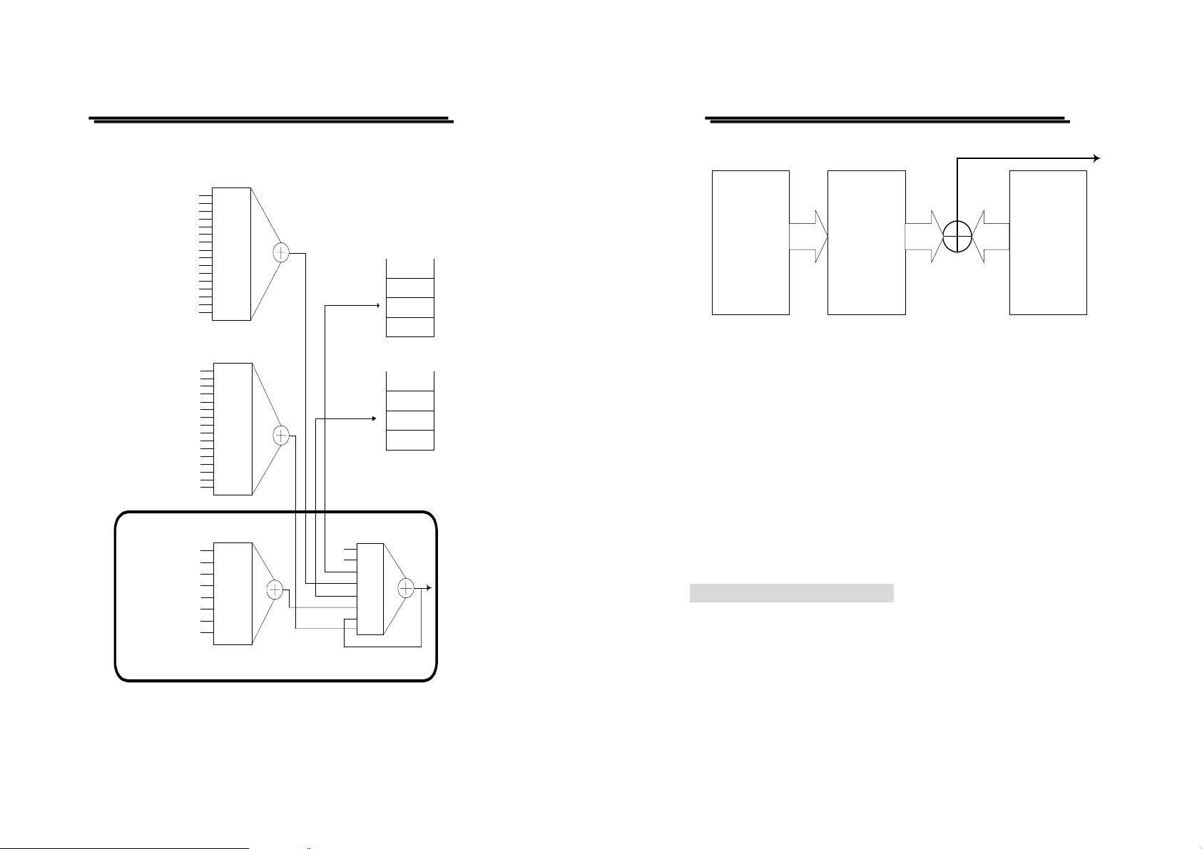
Structure of System
The sketch of the status and event reporting system is showed as
figure 7. Each component of th e sketch represents a set of register s and
queues that can read, rep ort, or enable the occurrence of certain ev ents
within the system.
If a specific event in the power supply sets a bit in a status register,
reading which can tell you what types of events have occurred.
Each bit in the status register corresponds to a bit in an enable register;
the enable bit must be high for the event to be reported to the Status Byte
Register.
A Service Request (SRQ) is the last event to occur. The SRQ requests an
interrupt on the GPIB to report events to the system controller.
Status Registers
⎯ 37 ⎯
There are two kinds of s tatus registers a re included to the programmabl e
power supplies.
z OPERation Status Registers ( CONDition, EVENt, and ENABle)
z QUEStionable Status Registers (CONDition, EVENt, and ENABle)
The lower level nodes: QUEStionable and OPERation each have three 16
bits registers: CONDition, EVENt, and ENABle. Figure 8 shows the
sequential relationship between these three types of registers and the
commands that relate to each register.
⎯ 38 ⎯
Page 21
PST & PSS & PSH SERIES PROGRAMMABLE POWER SUPPLY
PST & PSS & PSH SERIES PROGRAMMABLE POWER SUPPLY
Q UES tio n a b le
Status
Not Used
Not Used
Not Used
Not Used
Not Used
Not Used
Not Used
Not Used
Not Used
Not Used
Not Used
Not Used
Not Used
0
1
2
3
4
5
6
7
8
9
10
11
12
13
14
15
Summary Voltage
Summary Current
Summary OVP
O P ERation
Status
0
Not Used
1
Not Used
2
Not Used
3
Not Used
4
Not Used
5
Not Used
6
Not Used
7
Not Used
8
Not Used
9
Not Used
10
Not Used
11
Not Used
12
Not Used
13
Not Used
14
Not Used
15
Not Used
Standard Event Status Registers
Operation Complete
Device Dependent Error
Execution Error
Command Error
0
1
Not Used
Query Error
2
3
4
5
User Request
6
7
Power On
Summary of IEEE 488.2 Status Structure Registers
PROGRAMMER MANUAL
Error/Event Queue
Output Queue
Status Byte Register
0
Not Used
1
Not Used
E/E
2
QUES
3
MAV
4
ESB
5
RQS/MSS
6
7
OPER
SRQ
PROGRAMMER MANUAL
To SBR
Condition
Register
Event
Register
Enable
Register
Figure 8: Status registers and related commands
The CONDition register is a read-only register which monitors the
present state of the instrument. The CONDition register updates in real
time and the inputs are not latched or buffered. When a condition
monitored by the CONDition register becomes true, the bit for that
condition also becomes true (1). When the condition is false, the bit is 0.
The read-only EVENt register latches any false-to-true change in
condition. Once the bit in the EVENt register is set, it is no longer
affected by changes in the corresponding bit of the CONDition register.
The bit remains set until the controller reads it. The command *CLS
(Clear Status) clears the EVENt register.
QUEStionable Status Registers.
Table 4 shows the bit designations of the 16 bit QUEStionable Status
Register.
Figure 7. A graphic representation of the status registers and their connections.
⎯ 39 ⎯
⎯ 40 ⎯
Page 22

PST & PSS & PSH SERIES PROGRAMMABLE POWER SUPPLY
PST & PSS & PSH SERIES PROGRAMMABLE POWER SUPPLY
PROGRAMMER MANUAL
Table 4: QUEStionable Status Register
Bit 15 Bit 14 Bit 13 Bit 12 Bit 11 Bit 10 Bit 9 Bit 8
∗
NU NU NU NU NU Summary
OVP
Bit 7 Bit 6 Bit 5 Bit 4 Bit 3 Bit 2 Bit 1 Bit 0
NU NU NU NU NU NU
Summar
y Current
NU
Summary
Voltage
The command STATus:QUEStionable:CONDtion? Reads the
QUEStionable CONDition register but dose not clear it.
The command STATus:QUEStionable:EVENt? Reads the
QUEStionable EVENt Status register and clears it.
OPERation Status Regist ers
Table 5 shows the bit designations of the 16 bit OPERation Status
Register.
Table 5: OPERatio n S tat us R eg ister
Bit 15 Bit 14 Bit 13 Bit 12 Bi t 11 Bit 10 Bit 9 Bit 8
NU NU NU NU NU NU NU
Bit 7 Bit 6 Bit 5 Bit 4 Bit 3 Bit 2 Bit 1 Bit 0
NU NU NU NU NU NU NU NU
∗
NU: not used
PROGRAMMER MANUAL
Status Registers
There are two status registers are included to the power supply defined by
IEEE-488.1 and IEEE-488.2 standards.
z Status Byte Register (SBR)
z Standard Event Status Register (SESR)
Status Byte Register (SBR): The SBR (Table 6) summarizes the status of
all other registers and queues.
Table 6: Status Byte Register (SBR)
Bit 7 Bit 6 Bit 5 Bit 4 Bit 3 Bit 2 Bit 1 Bit 0
OPER RQS/MSS ESB MAV QUES E/E NU NU
The bit 0 and 1 are not used, so these bits are always zero. The bit 2
(Error and Event) indicates an error code is waiting to be read in the
Error Event Queue. The bi t 3 (QUES, QUEStionable) is the summary b it
for the QESR (QUEStionable Event Status Register). When the bit is
high it indicates that status is enabled and present in the QUES. The bit 4
(MAV, Message Available) indicates that output is available in the
output queue. The bit 5 (ESB, Event Status Bit) is the su mmary bit for
the Standard Event Status Register (SESR). When the bit is high it
indicates that status is enabled and present in the SESR. The bit 6 (RQS,
Request Service) is obtained from a serial poll and shows that the power
supply requests service from the GPIB controller. The bit 7 (OPER,
OPERation) is the summary bit for the OESR (OPERation EVENt
STATus Register).
⎯ 41 ⎯
⎯ 42 ⎯
Page 23

PST & PSS & PSH SERIES PROGRAMMABLE POWER SUPPLY
PST & PSS & PSH SERIES PROGRAMMABLE POWER SUPPLY
PROGRAMMER MANUAL
Use the serial poll or the *STB? Query to read the contents of the SBR.
The bits in the SBR are set and clear ed depending on the contents of the
Standard Event Status Register (SESR), the Standard Event Status
Register (SESR), and the Output Queue.
Standard Event Status Register (SESR): Table 7 shows the SESR
Table 7: Standard Event Status Register (SESR)
Bit 7 Bit 6 Bit 5 Bit 4 Bit 3 Bit 2 Bit 1 Bit 0
PON URQ CME EXE DDE QYE NU OPC
The bit 0 (OPC, Operation Complete) shows that the operation is
completed. This bit is active when all pending operations are completed
following an *OPC command. The bit 1 is always z ero. The bit 2 (QYE,
Query Error) indicates a command or query protocol error. The bit 3
(DDE, Device Error) shows that a device error occurred. The bit 4 (EXE,
Execution Error) shows that an error occurred while the power supply
was executing a command or query. The bit 5 (CME, Command Error)
shows that an error occurred while the power supply was parsing a
command or query. The bit 6 (USR, User Request) indicates the LOCAL
button was pushed. The bit 7 (PON, Power On) shows that the power
supply was powered on.
Use the *ESR? Query to read th e SESR. Read th e SES R and cl ear the bits
of the registers so that th e regist er can accumulate information about new
events.
Enable Registers
The enable registers d etermine whether cer tain events are r eported to the
Status Byte Register and SRQ. The programmable power supply has the
PROGRAMMER MANUAL
following enable registers .
z Event St atus En able Reg ister ( ESE R)
z OPERation Enable Register
z QUEStionable Enable Reg ister
z Service Request Enable Reg ister (SRER)
When one of the bits of the en ab le reg ister s is h igh and the cor respon ding
bit in the status register is high, the enable registers will perform a logical
OR function, the output that controls the set bit of the Status Byte
Register is high.
Various commands set the bits in the enable registers. The following
sections describe the enable registers and the commands that set them.
Event Status Enable Register (ESER): The ESER controls which types of
events are summarized by the Event Status Bit (ESB) in the SBR. The
bits of the ESER correspond to the bits of the SESR.
Use the *ESE command to set the bits in ESER. Use the *ESE? query to
read it.
OPERation Enable Register: Even though the OPERation Enable
Register is presen t in the programmable power supplies, the OPERation
registers do not report any conditions.
QUEStionable Enable Register: The QUEStionable Enable Register
controls which types of events are summarized by the QUES status bit in
the SBR. Use the STATus:QUEStionable:ENABle command to set
the bits in the QUEStionable Enable register. Use the
STATus:QUEStionable:ENABle? query to read it.
Service Request Enable Register (SRER): The SRER controls which bits
in the SBR generate a service request.
Use the *SRE command to set the SRER. Use the *SRE? query to read
it.
⎯ 43 ⎯
⎯ 44 ⎯
Page 24

PST & PSS & PSH SERIES PROGRAMMABLE POWER SUPPLY
PST & PSS & PSH SERIES PROGRAMMABLE POWER SUPPLY
PROGRAMMER MANUAL
Queues
The output queue is included to power supplies.
Output Queue: The programmable power supplies store query responses
in the output queue by succeeding the IEEE 488.2 protocol. If the power
supply receives a new command or query message after a message
terminator, the power supply will clear and reset this queue each time.
The computer must read a query response before it sends the next
command (or query) or it loses response to earlier quer ies.
Error/Event Queues
When an error or event occurs, the output queue s tores the message. Th e
output queue stores and reports the messages on a FIFO (first in first out)
state. The SYSTem:ERRor? query reads the next item from the output
queue. If output queue overflows, the error message is –350, “Queue
overflow”; the queue can’t store or report succeeding messages till it
is read or cleared.
Error Message
Table 8 lists the SCPI error messages for the programmable power
supplies.
Table 8 The error messages for the power supplies
SCPI Error Code and Description SESR Bit
0, “No error”
-100, “Command error” 5
-200, “Execution Error” 4
-221, “Settings conflict” 4
-221, “Settings conflict; Timer setting error” 4
-221, “Settings conflict; Overvoltage protection setting error” 4
-221, “Settings conflict; Voltage setting error” 4
PROGRAMMER MANUAL
-221, “Settings conflict; Current setting error” 4
-221, “Settings conflict; Recall setting error” 4
-221, “Settings conflict; Store setting error” 4
-222, “Data out of range” 4
-222, “Data out of range; Voltage too large” 4
-222, “Data out of range; Current too large” 4
-222, “Data out of range; Voltage too small” 4
-222, “Data out of range; Current too small” 4
-240, “Hardware Error” 4
-300, “Device-specific error” 3
-300, “Device-specific error; Overcurrent protection er ror” 3
-300, “Device-specific error; Overvoltage protection error” 3
-300, “Device-specific error; Overtemperature protection
error”
-300, “Device-specific error; Calibration current error” 3
-300, “Device-specific error; Calibration voltage error” 3
-300, “Device-specific error; Calibration overvoltage
protection error”
-310, “System error” 3
-313, “Calibration memory lost” 3
-330, “Self-test failed” 3
-330, “Self-test failed; CPU test error” 3
-330, “Self-test failed; RAM test error” 3
-330, “Self-test failed; ROM test error” 3
-330, “Self-test failed; DAC/ADC test error” 3
-350, “Queue overflow” 3
-410, “Query INTERRUPTED” 2
-420, “Query UNTERMINATED” 2
-430, “Query DEADLOCKED” 2
3
3
⎯ 45 ⎯
⎯ 46 ⎯
 Loading...