

Page 1

Programmable DC Electronic
Load
PEL-2000 Series
USER MANUAL
GW INSTEK PART NO. 82EL-20040MA1
ISO-9001 CERTIFIED MANUFACTURER
Page 2

March 2010
This manual contains proprietary information, which is protected by
copyright. All rights are reserved. No part of this manual may be
photocopied, reproduced or translated to another language without
prior written consent of the Good Will company.
The information in this manual was correct at the time of printing.
However, Good Will continues to improve products and reserves the
right to change specification, equipment, and maintenance
procedures at any time without notice.
Good Will Instrument Co., Ltd.
No. 7-1, Jhongsing Rd., Tucheng City, Taipei County 236, Taiwan.
Page 3

Table of Contents
Table of Contents
SAFETY INSTRUCTIONS ................................................... 5
GETTING STARTED ......................................................... 10
Main Features ...................................... 12
Series Overview ................................... 13
Package Contents and Accessories....... 15
Measurement Overview ....................... 16
Front Panel Overview ........................... 17
Display Overview – Mainframe ............ 22
Rear Panel Overview ............................ 25
Front Panel Overview – Load Module ... 28
LED Display Overview – Load Module .. 32
Installation .......................................... 35
Load Connections ................................ 43
Frame Link Connection ........................ 54
Channel Control Connection ................ 56
Go/NoGo Connection .......................... 59
OPERATING DESCRIPTION ............................................. 60
Operating Mode Description ............... 61
Run Program ........................................ 71
Sequence ............................................. 74
Parallel Dynamic Loading .................... 78
Configurations Description .................. 79
Interface and File System ..................... 89
TUTORIALS ..................................................................... 96
Local loads .......................................... 97
Single Channel Load ............................ 99
Programming ..................................... 101
Sequences .......................................... 103
3
Page 4

PEL-2000 Series User Manual
Frame Link ......................................... 104
Channel Control ................................. 106
General Configuration Options .......... 108
OPERATION ................................................................... 109
Local Mode Operation ....................... 112
Mainframe Basic Operation ............... 119
Channel Configuration ....................... 160
Mainframe Configuration ................... 180
Interface Configuration (settings) ...... 195
Save / Recall ...................................... 201
INTERFACE .................................................................... 232
Interface Configuration ...................... 233
FAQ ............................................................................... 241
APPENDIX ..................................................................... 242
Fuse Replacement .............................. 242
Battery Replacement .......................... 243
Firmware Update ............................... 244
Calibration ......................................... 245
Range Chart ....................................... 246
Default Settings ................................. 251
Specifications .................................... 253
Dimensions ....................................... 261
EC Declaration of Conformity ............. 263
INDEX ............................................................................ 264
4
Page 5
SAFETY INSTRUCTIONS
SAFETY INSTRUCTIONS
This chapter contains important safety
instructions that you must follow when operating
the PEL-2002/PEL-2004, and when keeping it in
storage. Read the following before operating the
PEL-2002/2004 to ensure your safety and to keep
the PEL-2000 series in the best possible condition.
Safety Symbols
These safety symbols may appear in this manual or on the PEL2002/2004.
WARNING
CAUTION
Warning: Identifies conditions or practices that
could result in injury or loss of life.
Caution: Identifies conditions or practices that
could result in damage to THE PEL-2002/2004 or
to other properties.
DANGER High Voltage
Attention Refer to the Manual
Protective Conductor Terminal
Earth (ground) Terminal
5
Page 6
PEL-2000 Series User Manual
Do not dispose electronic equipment as unsorted
municipal waste. Please use a separate collection
facility or contact the supplier from which this
instrument was purchased.
Safety Guidelines
General
Guideline
Do not place any heavy object on the PEL-
2002/2004.
CAUTION
Avoid severe impact or rough handling that
leads to damaging the PEL-2002/2004.
Do not discharge static electricity to the PEL-
2002/2004.
Do not block or obstruct the cooling fan vent
openings.
Do not perform measurement at circuits directly
connected to Mains (Note below).
Do not disassemble the PEL-2002/2004 unless
you are qualified as service personnel.
The equipment is not for measurements
performed for CAT II, III and IV.
(Measurement categories) EN 61010-1:2001 specifies the
measurement categories and their requirements as follows. The
PEL-2002/2004 falls under category I.
Measurement category IV is for measurement performed at the
source of low-voltage installation.
Measurement category III is for measurement performed in the
building installation.
Measurement category II is for measurement performed on the
circuits directly connected to the low voltage installation.
Measurement category I is for measurements performed on
circuits not directly connected to Mains.
6
Page 7
SAFETY INSTRUCTIONS
Power Supply
WARNING
Fuse
WARNING
Battery
WARNING
AC Input voltage: 115V/230V switchable,
50/60Hz
The power supply voltage should not fluctuate
more than 15%.
Connect the protective grounding conductor of
the AC power cord to an earth ground, to avoid
electrical shock.
Fuse type: T3.15A/250V
Make sure the correct type of fuse is installed
before power up.
To avoid fire, only replace the fuse with the
specified type and rating.
Disconnect the power cord before fuse
replacement.
Make sure the cause of a fuse blowout is fixed
before replacing the fuse.
Battery type: CR17345 (See page 243).
When replacing the battery ensure that the
correct make and model are used.
Cleaning the
PEL-2000
Disconnect the power cord before cleaning.
Use a soft cloth dampened in a solution of mild
detergent and water. Do not spray any liquid.
Do not use chemicals or cleaners containing
harsh material such as benzene, toluene, xylene,
and acetone.
7
Page 8

PEL-2000 Series User Manual
Operation
Environment
Storage
environment
Location: Indoor, no direct sunlight, dust free,
almost non-conductive pollution (Note below)
Temperature: 0°C to 40°C
Altitude: Up to 2000m
Transient Overvoltage on the main supply is
2500V.
(Pollution Degree) EN 61010-1:2001 specifies the pollution degrees
and their requirements as follows. THE PEL-2002/2004 falls under
degree 2.
Pollution refers to “addition of foreign matter, solid, liquid, or
gaseous (ionized gases), that may produce a reduction of dielectric
strength or surface resistivity”.
Pollution degree 1: No pollution or only dry, non-conductive
pollution occurs. The pollution has no influence.
Pollution degree 2: Normally only non-conductive pollution
occurs. Occasionally, however, a temporary conductivity caused
by condensation must be expected.
Pollution degree 3: Conductive pollution occurs, or dry, non-
conductive pollution occurs which becomes conductive due to
condensation which is expected. In such conditions, equipment
is normally protected against exposure to direct sunlight,
precipitation, and full wind pressure, but neither temperature
nor humidity is controlled.
Location: Indoor
Relative Humidity: < 80%
Disposal
8
Temperature: −10°C to 70°C
Do not dispose this instrument as unsorted
municipal waste. Please use a separate collection
facility or contact the supplier from which this
instrument was purchased. Please make sure
discarded electrical waste is properly recycled to
reduce environmental impact.
Page 9
SAFETY INSTRUCTIONS
Power cord for the United Kingdom
When using the PEL-2002/2004 in the United Kingdom, make sure
the power cord meets the following safety instructions.
NOTE: This lead/appliance must only be wired by competent persons
WARNING: THIS APPLIANCE MUST BE EARTHED
IMPORTANT: The wires in this lead are coloured in accordance with the
following code:
Green/ Yellow: Earth
Blue: Neutral
Brown: Live (Phase)
As the colours of the wires in main leads may not correspond with the coloured
marking identified in your plug/appliance, proceed as follows:
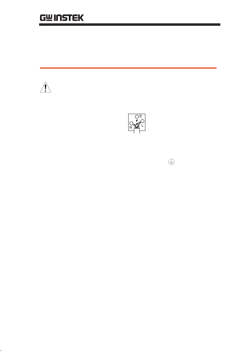
The wire which is coloured Green & Yellow must be connected to the Earth
terminal marked with either the letter E, the earth symbol
Green/Green & Yellow.
The wire which is coloured Blue must be connected to the terminal which is
marked with the letter N or coloured Blue or Black.
The wire which is coloured Brown must be connected to the terminal marked
with the letter L or P or coloured Brown or Red.
If in doubt, consult the instructions provided with the equipment or contact the
supplier.
This cable/appliance should be protected by a suitably rated and approved
HBC mains fuse: refer to the rating information on the equipment and/or user
instructions for details. As a guide, a cable of 0.75mm2 should be protected by a
3A or 5A fuse. Larger conductors would normally require 13A types,
depending on the connection method used.
Any exposed wiring from a cable, plug or connection that is engaged in a live
socket is extremely hazardous. If a cable or plug is deemed hazardous, turn off
the mains power and remove the cable, any fuses and fuse assemblies. All
hazardous wiring must be immediately destroyed and replaced in accordance
to the above standard.
or coloured
9
Page 10
PEL-2000 Series User Manual
GETTING STARTED
This chapter describes the features and functions of the
PEL-2002/2004, including the front and rear panel
appearance, panel installation and connection types. Use
the Tutorial section for quick access to step by step
instructions on the main functions.
Main Features ................................................................. 12
Series Overview ............................................................... 13
Package Contents and Accessories .................................. 15
Measurement Overview ................................................... 16
Front Panel Overview ...................................................... 17
Display Overview – Mainframe ........................................ 22
10
Page 11

GETTING STARTED
Rear Panel Overview ........................................................ 25
Front Panel Overview – Load Module ............................... 28
LED Display Overview – Load Module ............................. 32
Installation ..................................................................... 35
Load Module Installation ..................... 35
GPIB Installation ................................. 38
Rack Mount Installation ....................... 39
Channel Number .................................. 40
Power Up & Self Test ........................... 41
Load Connections ........................................................... 43
Precautions and Procedures ................ 43
Remote (Sense) Connection ................. 48
Single Load Connections ...................... 50
Parallel Load Connections.................... 52
Frame Link Connection .................................................... 54
Channel Control Connection ............................................ 56
Go/NoGo Connection ..................................................... 59
11
Page 12

PEL-2000 Series User Manual
Main Features
Description
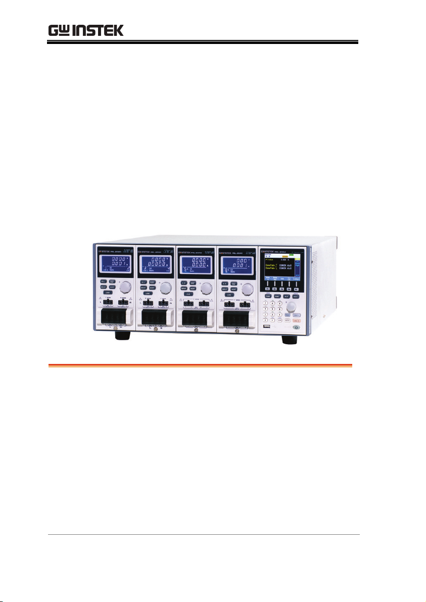
The PEL-2002 and 2004 are multichannel
programmable DC electronic load mainframes.
The PEL-2002 mainframe is able to hold 2 load
modules, whilst the PEL-2004 is able to hold 4. The
flexible module configuration allows the
mainframes to either sink multiple loads
independently or large loads when used in
parallel.
The PEL-2000 series support three operation
modes: constant current (CC), constant voltage
(CV and CV+CC) and constant resistance (CR).
Constant current and constant resistance mode can
operate in either static or dynamic mode.
Feature Overview
12
Flexible operation with removable load modules
Multiple independent isolated channels
High performance, up to 5 digit resolution
High slew rate enabling a high response speed
High capacity when frame linked
Different load module types can be used in the
same mainframe
Supports rack mount installation (PEL-2004)
Supports frame link connections, with up to 4
slave units
Color LCD display
120 different sets of programmable sequences
Accurate load simulation using Sequences
4 panel setups
USB flash drive support
Page 13
GETTING STARTED
Interface
USB
RS-232C
GPIB (optional)
Series Overview
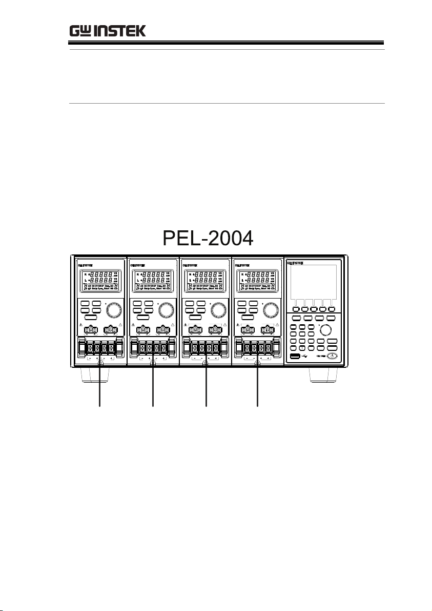
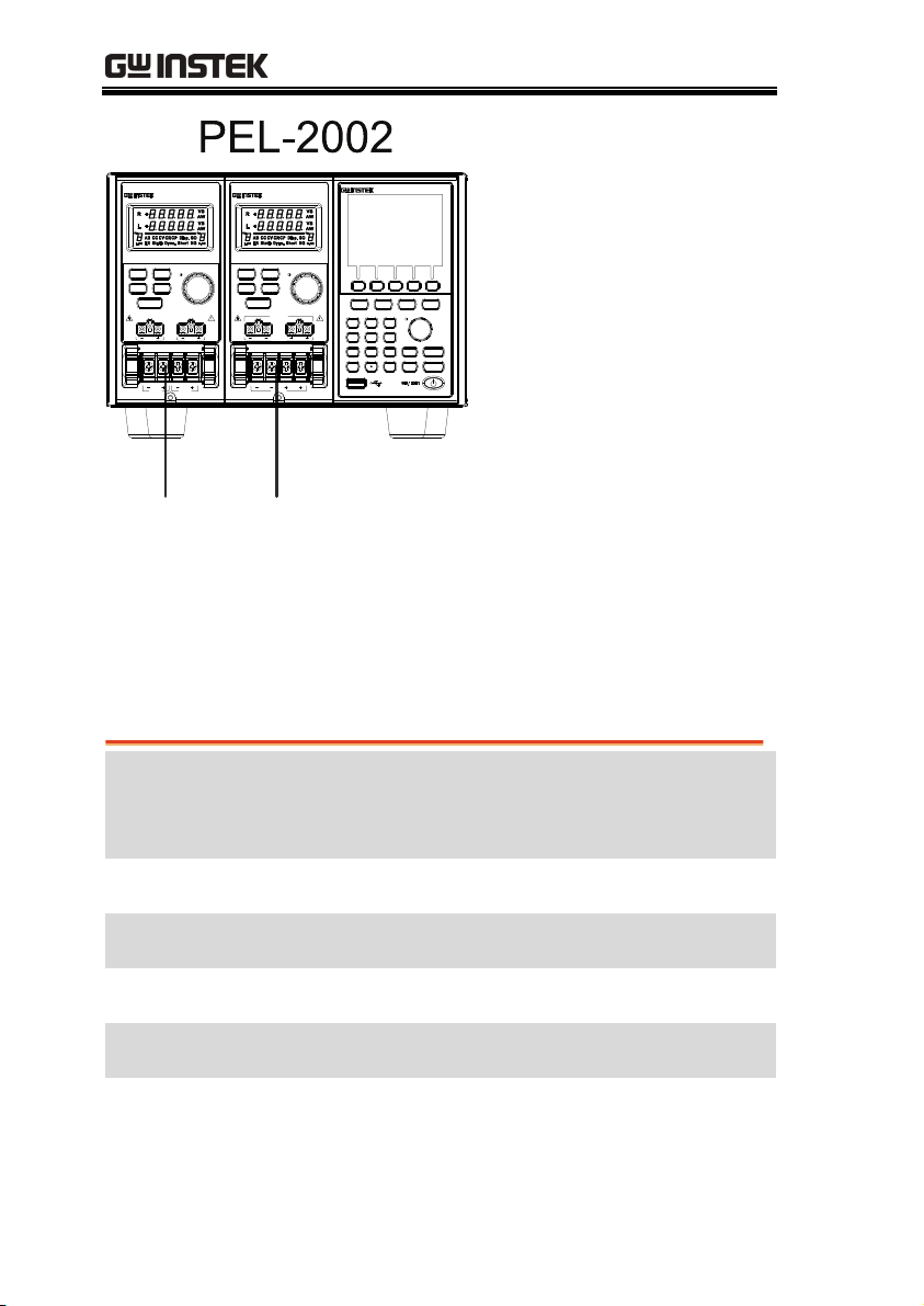
The PEL-2000 series comprises of two different Mainframes: the PEL2002 and the PEL-2004. The Mainframes differ by the number of load
modules that can be accommodated. The PEL-2002 has two load
module slots whilst the PEL-2004 has 4. There are 4 different load
module models, the PEL-2020, PEL-2030, PEL-2040 and PEL-2041.
DISPLAY
LOAD
V sense V sense
L
MAX
80VDC
80VDC
PEL-2020
STATIC/
DYNA.
SHORT
MAX MAX
L
DC Electronic Load
L
20A/ 80V,100W
20A/ 80V,100W
R
L
R
MAX
80VDC
80VDC
R
DC Electronic Load
5A/ 80V, 30W
L
40A/ 80V,250W
PEL-2030
R
STATIC/
R/LR/L
DYNA.
DISPLAY
SHORT
LOAD
V senseV sense
R
MAX
MAX
80VDC
80VDC
MAXMAX
80VDC
80VDC
R
L
DC ElectronicLoad
PEL-2040
70A/ 80V,350W
STATIC/
A/B
DYNA.
DISPLAY
SHORT
LOAD
V sense
MAX
80VDC
MAX
DC Electronic Load
PEL-2041
10A/ 500V,350W
STATIC/
A/B
DYNA.
SHORT
DISPLAY
LOAD
V sense
MAX
500VDC
MAX
500VDC80VDC
456
1
P0 LOCK
0
DC ElectronicLoad
PEL-2004
F1
LOCAL UTILITY
FILEFUNC
CHAN
P9P7 P8
9
87
P6P4 P5
P3P1 P2
PRESET
3
2
CAL.
ENTER
CLEAR
F5F4F3F2
HELP
SHIFT
ON/
LOAD
OFF
PEL-2040 PEL-2041PEL-2020 PEL-2030
13
Page 14
PEL-2000 Series User Manual
DISPLAY
LOAD
Vsense Vsense
L
MAX
80VDC
MAX MAX
80VDC
L
DC ElectronicLoad
20A/ 80V, 100W
L
PEL-2020
20A/ 80V, 100W
R
STATIC/
DYNA.
SHORT
R
MAX
80VDC
80VDC
R
DC ElectronicLoad
PEL-2040
70A/80V ,350W
STATIC/
A/BR/L
DYNA.
DISPLAY
SHORT
LOAD
Vsense
MAX
80VDC
MAX
80VDC
CHAN
78
12
0
PEL-2002
F1
F2 F3 F4 F5
FUNC FILE
P8P7 P9
P5P4 P6
P2P1 P3
CAL.
DC Electronic Load
UTILITYLOCAL
HELP
9
654
PRESET
SHIFT
3
LOCKP0
ON/
CLEAR
LOAD
ENTER
OFF
PEL-2020 PEL-2040
The 4 different load module models each differ in the amount of current,
voltage and power and the amount of channels that the load module
can accommodate. The procedures in this manual will be load module
model independent unless specifically stated. Below is a table showing
the basic differences between each load module model. For detailed
specifications, please see page 253.
Load Module Channels
Power (W)
CH L/R
Current (A)
Range
Voltage (V)
Low/High
PEL-2020
PEL-2030 (30/250W)
(100Wx2) 2 100/100 2/20 1-80
2 30/250 5/4/40 1-80
PEL-2040 1 350 7/70 1-80
PEL-2041 1 350 1/10 2.5-500
14
Page 15

GETTING STARTED
Package Contents and Accessories
The PEL-2000 electronic load generator has a number of standard
and optional accessories that can be ordered. For more information
please visit the GW Instek website at www.gwinstek.com
consult your authorized distributor for details.
Standard
Accessories
Power Cable Mains power cable (region dependent)
User Manual PEL-2000 Series Electronic DC load User Manual
GTL-120 Load cables 2X red, 2X black (per load module)
GTL-121 Remote sense cables , 1X red, 1X black (per load
Options Description
PEL-2020
Description
(region dependent)
module)
Load Module
or
PEL-2030
PEL-2040
PEL-2041
PEL-001 GPIB interface (Factory installed)
Optional
Accessories
PEL-002 PEL-2000 Rack Mount kit (handle only)
GTL-232 RS-232C
GTL-246 USB
GTL-248 GPIB cable
GTL-249 Frame link
Description
15
Page 16
PEL-2000 Series User Manual
Measurement Overview
The PEL-2000 series has a number of different operating modes that
are completely configurable. All the modes have customizable
Go/NoGo limits, range limits, timers, slew rates, alarms and
protection limits. To make tests, Programs and Sequences can be
created.
Function
Description
Constant Current
Mode (CC)
Constant Voltage
Mode (CV)
Constant
Resistance Mode
(CR)
Programmable
Sequences
(Prog.)
Sequences (Seq.)
In constant current mode, the PEL-2002/2004 will
sink a constant amount of current, regardless of
the voltage.
Under constant voltage mode, the voltage remains
unchanged, regardless of the current.
In constant resistance mode, the resistance load
will remain unchanged as the voltage and current
remain proportional.
The PEL 2000 series supports programming
sequences. With up to 120 different memory
settings in 12 programs with 10 sequences.
Used to create load profiles to accurately simulate
a load. Sequences can be created for each channel.
16
Page 17
GETTING STARTED
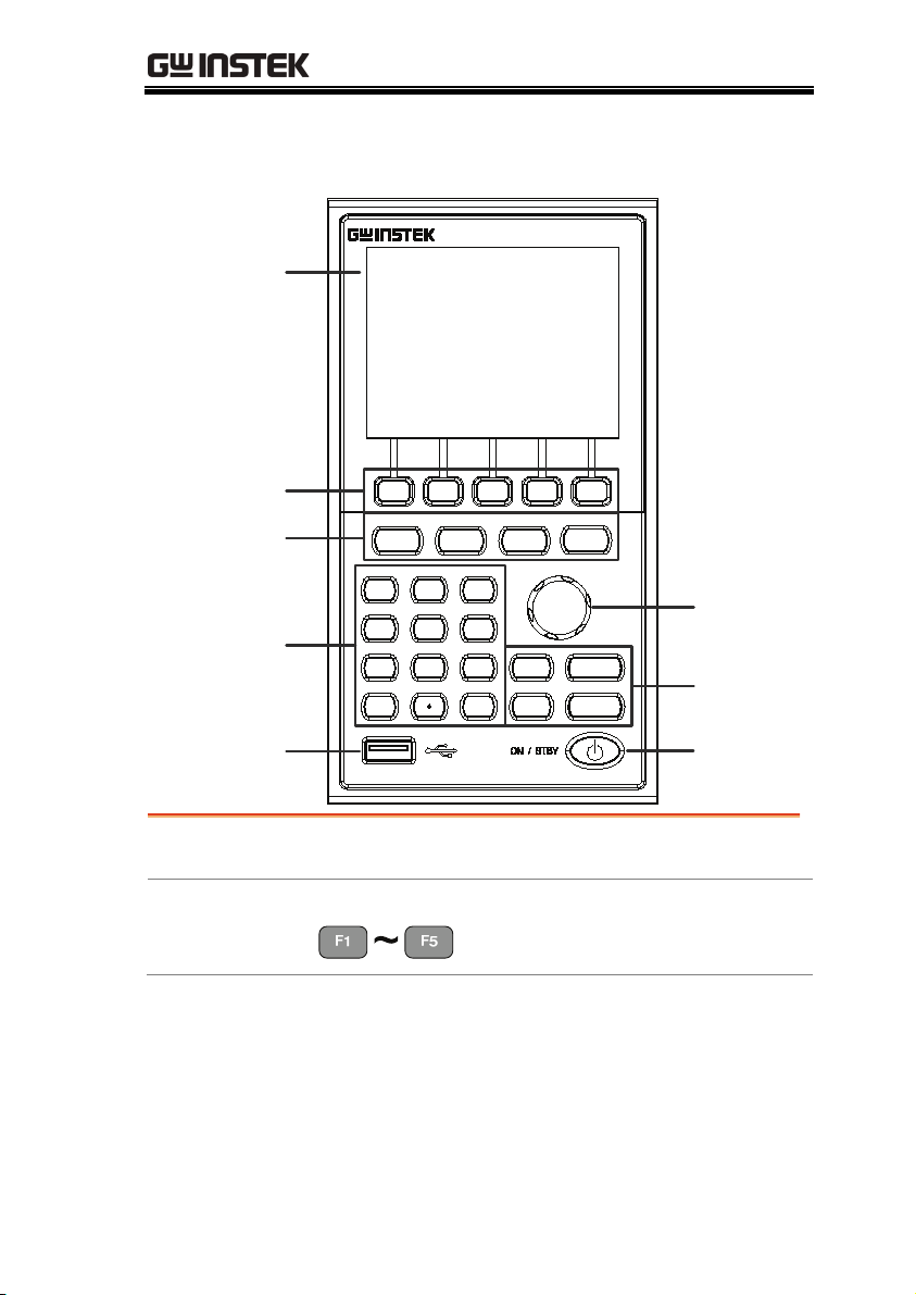
Front Panel Overview
LCD display
Function keys
System Keys
Number Pad
LCD display
PEL-2002
F1
LOCAL
CHAN
P9P7 P8
9
87
456
P0 LOCK
0
P6P4 P5
P3P1 P2
21
3
CAL.
CLEAR
FILEFUNC
ENTER
DC Electronic Load
F5F4F3F2
UTILITY
HELP
SHIFTPRESET
LOAD
320 by 240, TFT LCD display.
Selector
Knob
Operation
ON /
OFF
keys
PowerUSB input
Function keys
Assigned to the menu functions on
the bottom of the display.
17
Page 18
PEL-2000 Series User Manual
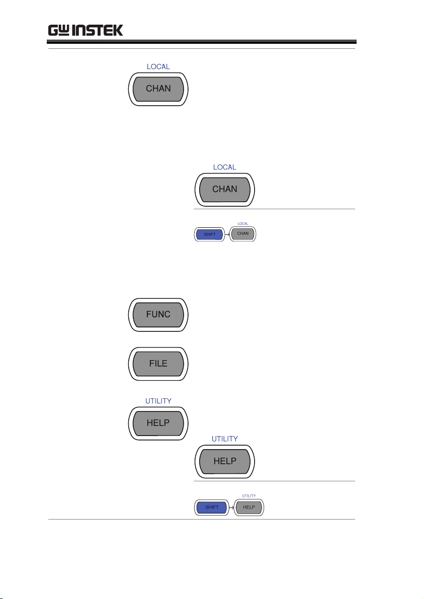
System Keys
CHAN/LOCAL is used to select
the load channel. Combined with
the shift key, Local is used to
activate/deactivate local control
(during remote control via the
interface or frame link
connections).
Brings up the
Channel Menu.
Used to activate
local control mode
during remote
control via the
interface
Used to access the Program or
Sequence menu.
Used to access the File menu.
Brings up the Help menu and
utility menu.
Provides help for
the last function
/key pressed.
Activates the
Utility Menu.
18
Page 19
GETTING STARTED
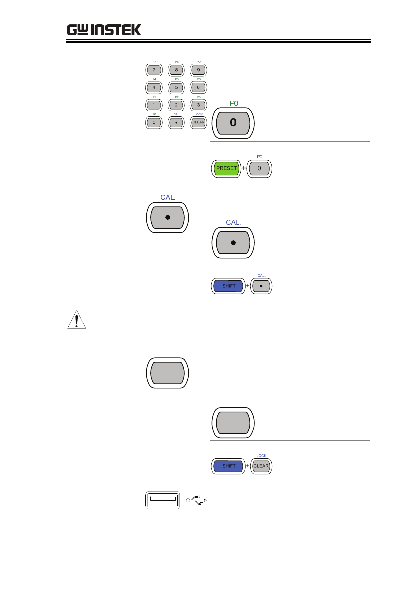
Number pad
Note
Enter numerical values, or to
save/recall presets (P0-P9).
Number values.
Preset numbers P0P9.
Decimal point and Calibration key
Decimal point.
Activate calibration
mode.
Please note, calibration mode is not supported.
Please see your distributor for calibration needs.
LOCK
CLEAR
Clears current values. Alternative
function locks the keys and the
Selector knob.
LOCK
CLEAR
Clears the current
value.
Locks all the keys
and Selector knob.
USB Input
USB flash memory slot.
19
Page 20
PEL-2000 Series User Manual
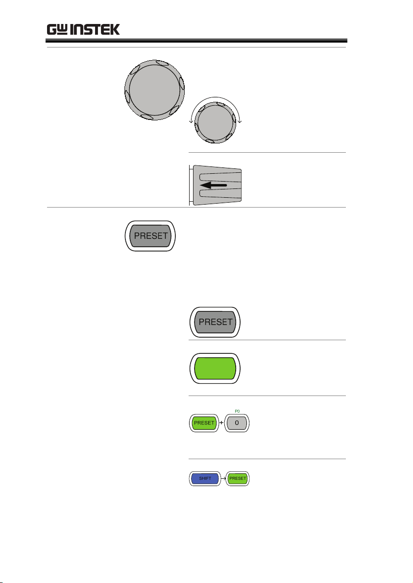
Selector Knob
Operation Keys
Used to select operations and to
increase/decrease values.
When turned left or
right moves the
cursor in menus or
changes the selected
item or value.
When pushed
down, acts as the
Enter key.
Saves and recalls preset settings
and values.
When pressed in combination with
the number pad, Presets P0-P9 can
be recalled or saved.
Inactive
Active. Used in
PRESET
combination with
the number pad
and/or shift key.
Press to recall a
channel preset
Hold to save a
channel preset
Press to recall all
channel presets.
Hold to save all
channel presets.
20
Page 21
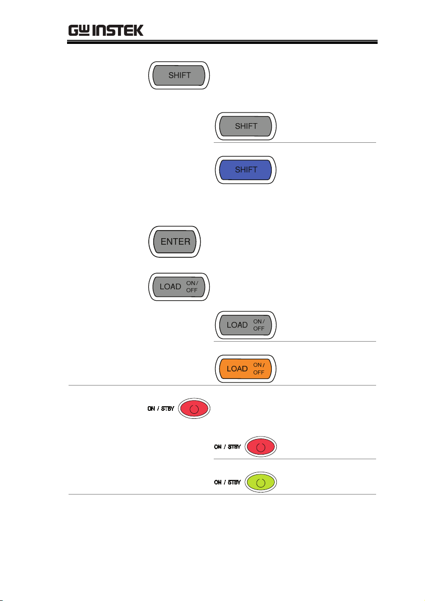
GETTING STARTED
The shift key is used to access
alternate functions assigned to
select keys
Inactive
Active. When active
the shift key can be
used to access the
Local and Utility
menus.
Confirms selections.
Turns the current load/channel on
or off
Load is currently
off. (unlit)
Load is currently on.
(orange light)
Power
Turns the unit on or into standby
mode.
Standby mode.
On.
21
Page 22
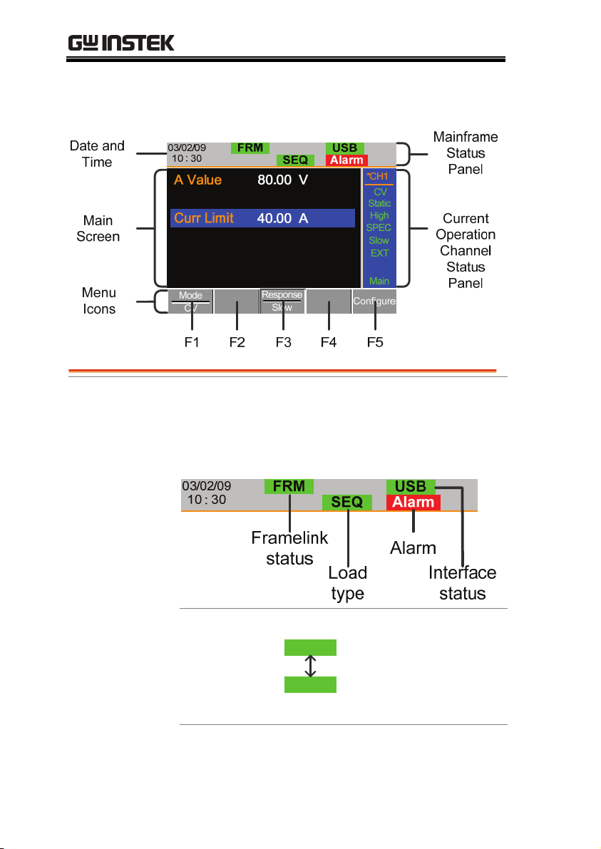
PEL-2000 Series User Manual
Display Overview – Mainframe
Mainframe Status
Panel
The Mainframe Status Panel displays the status of
the Mainframe interface, programs and alarm
status.
Frame Link
Status
FRM
FRS
Indicates Frame Link is
turned on and that the
mainframe is set as either
a master (FRM) or slave
(FRS) unit.
22
Page 23
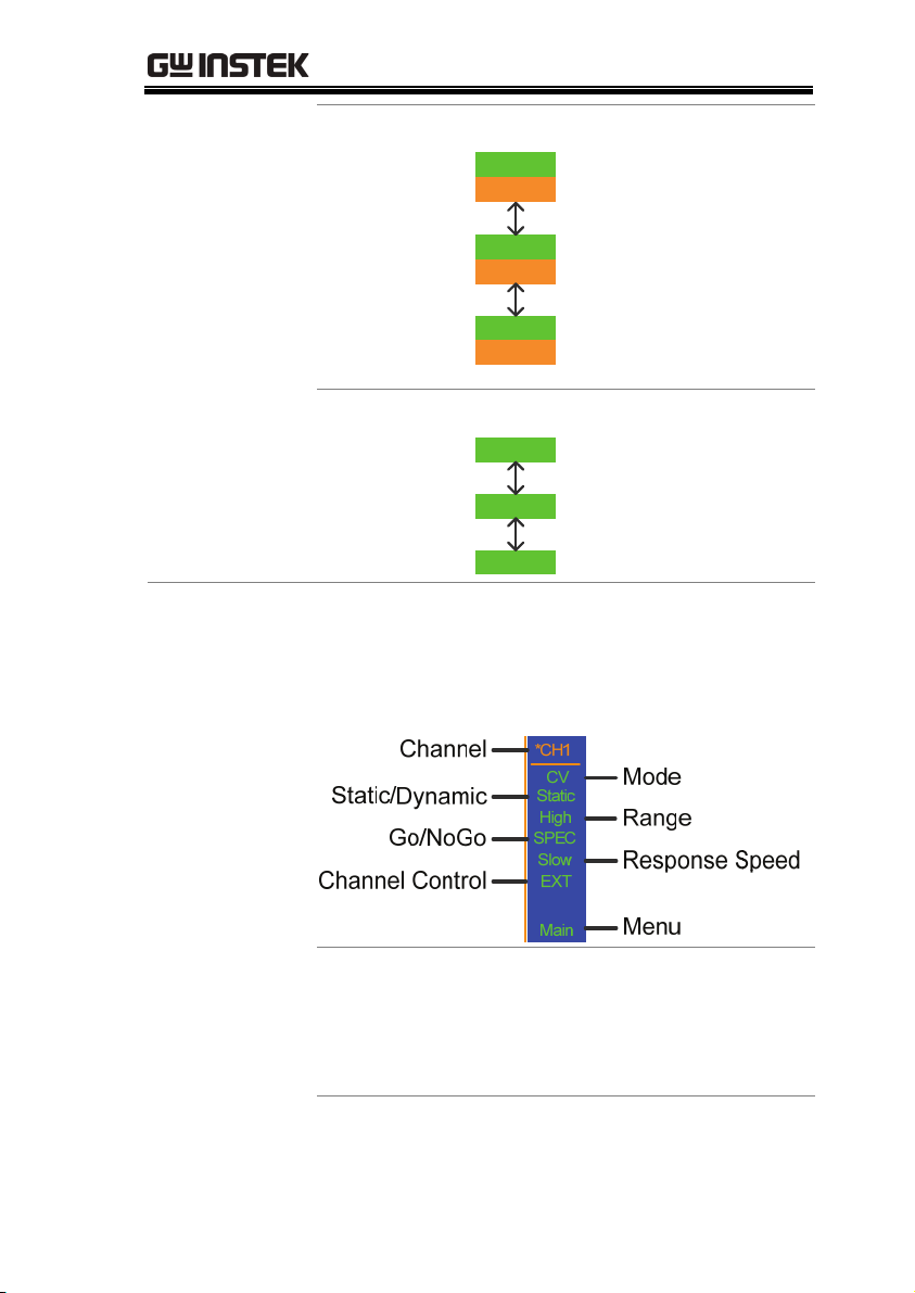
GETTING STARTED
Current
Operation
Channel Status
Panel
Load Type
Interface Status
LOAD
LOAD
PROG
PROG
SEQ
SEQ
RS232
GPIB
The Load Type Icon
indicates if a Sequence
(SEQ) or Program
(PROG) is turned on. If
not then LOAD is
displayed as default.
When any Load type is
running, their icon will
turn orange.
The interface status icon
displays which interface
type is set.
USB
The Current Operation Channel Status panel
generally displays the status of the current
channel.
Channel *CH1~
*CH8
Displays the current
channel.
An asterisk * denotes
independent mode for
the channel.
23
Page 24
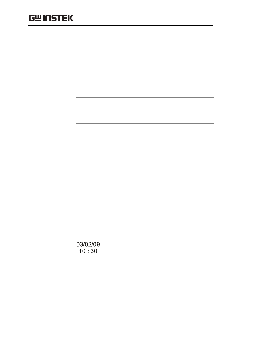
PEL-2000 Series User Manual
Mode CC
CR
Displays the current
mode.
CV
Static /
Dynamic
Range High
Displays whether the channel is in
Static or Dynamic mode.
Displays High or Low
Low
range.
Go/NoGo SPEC If Go/NoGo is turned
on, SPEC will be
displayed.
Response
Speed
Slow
Fast
In CV mode the response
speed will be shown,
Slow or Fast.
Channel
Control
EXT When Channel Control is
set to External, EXT will
be displayed.
Menu
Main
Conf
s_edit
File
s_loop
Shows the current menu.
= Chan menu
= ChanConfigure menu
= ChanSeq.Edit menu
= File menu
= ChanSeq.EditLoop
menu
Date and Time
Main Screen
Menu Icons
Main display screen
F1~F5
The date is displayed as
Month/Day/Year and the time is
set as a 24-hour time notation.
Each Menu Icon is controlled by
the F1~F5 function keys directly
below.
24
Page 25
GETTING STARTED
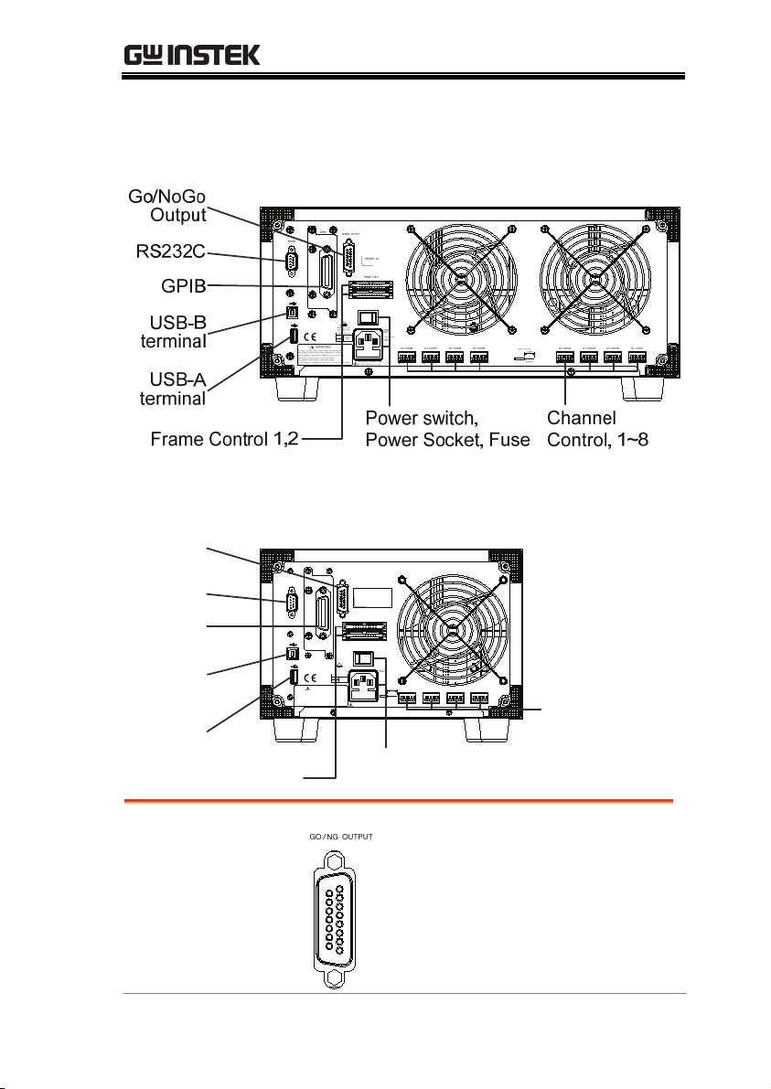
Rear Panel Overview
PEL-2004
PEL-2002
Go/NoGo
Output
RS232C
GPIB
GPIB
GO / NG OUTPUT
RS232C
SER. NO. LB
FRAME CONT
1
2
WARNING
TO AVOID ELECTRIC SHOCK THE POWER CORD PROTECTIVE
GROUNDING CONDUCTOR MUST BE CONNECTED TO GROUND.
FOR CONTINUED FIRE PROTECTION. REPLACE FUSE ONLY WITH
250V FUSE OF THE SPECIFIED TYPE AND RATING.
NO OPERATOR SERVICEABLE COMPONENTS INSIDE.
DO NOT REMOVE COVERS. REFER SERVICING TO QUALIFIED PERSONNEL.
REPLACE FUSE
AS SPECIFIED
AC
FUSE RATING
115V
T 3.15A
120 VA MAX
250V
230V
50/60 Hz
STRIP GAUGE
10.0 mm
CH CONT 41CH CONT 31CH CONT 21CH CONT 1
DISCONNECT POWER CORD
BEFORE REPLACING FUSE
AWG 24
1
Channel
Control, 1~4
USB-B
terminal
USB-A
terminal
Power switch,
Frame Control 1,2
Go/NoGo
Output
Power Socket, Fuse
The Go/NoGo Output
terminal outputs a pass
(high)/fail (low) voltage for
each channel.
See page 239, 59 for details.
25
Page 26

PEL-2000 Series User Manual
RS232 port/
GPIB port
USB-A(host)/
USB-B (device)
port
Frame Control
Port
The RS232 and GPIB port is
used for remote control
connections.
RS-232C: DB-9 pin male
GPIB: 24-pin female
See pages 233, 234 for remote
control details.
The USB-B (device) port, like
the RS232/GPIB port is used
for remote control. Like the
front panel, the USB-A port is
used for data storage.
See page 89 for interface
details.
The Frame Control port is
used for Frame Link
connections. Mainframes are
daisy-chained together. There
are two Frame control ports.
1: Slave
2: Master
Connection type: MIL 20-pin
connector.
For details about frame link
connections see page 54, 236.
Power Switch
26
External Power Switch
Page 27

GETTING STARTED
Power Socket/
Fuse
Channel
Control port
(1~8)
The power supply socket
accepts the AC mains Voltage.
The fuse holder is located
below the power socket.
Power: 50/60 Hz (180 VA)
Fuse: T3.15A/250V
For fuse replacement details
see page 242.
Each channel has a dedicated
Channel control port to
enable external monitoring
and control. The channel
control port has 6 wire sockets
that are screw-less and self
clamping.
Required wire gauge: 24
AWG
For connection or
specification details see pages
56 & 235.
27
Page 28
PEL-2000 Series User Manual
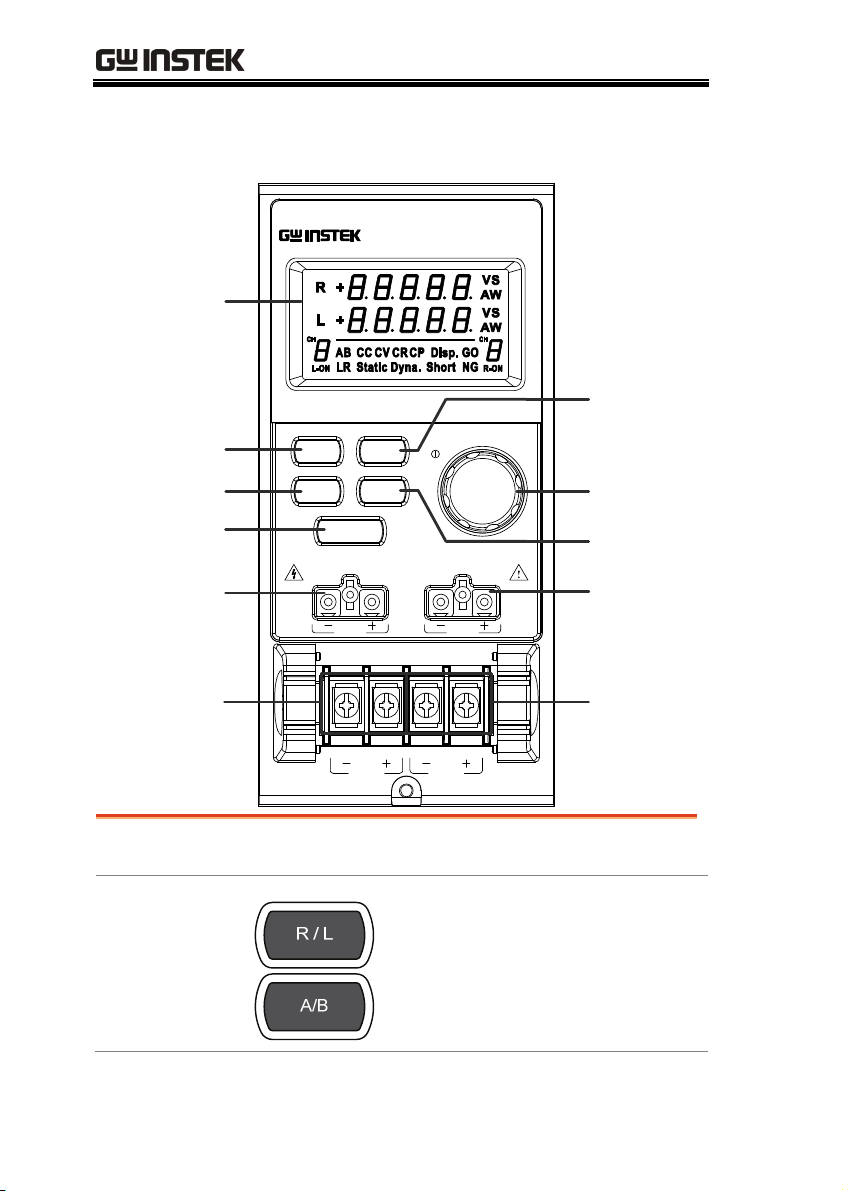
Front Panel Overview – Load Module
DC Electronic Load
L
20A / 80V , 100W
20A / 80V , 100W
R
MAX
80V DC
R
LED
display
R/L A/B Key
Display Key
Load Key
V Sense L
PEL-2020
R/L
DISPLAY
L
STATIC/
DYNA.
SHORT
LOAD
V sense V sense
MAX
80V DC
Static/
Dynamic
Key
Selector
Knob
Short Key
V Sense R
Terminals
(Left)
LED display
Right/Left Key
or
A/B Key
28
MAX MAX
80V DC
L
80V DC
R
2x5 digit custom LED display.
The L/R key is used to switch
between the right and left load
channel on a dual channel load
module. The A/B key is used to
switch between A&B Values for
single channel load modules.
Terminals
(Right)
Page 29
GETTING STARTED
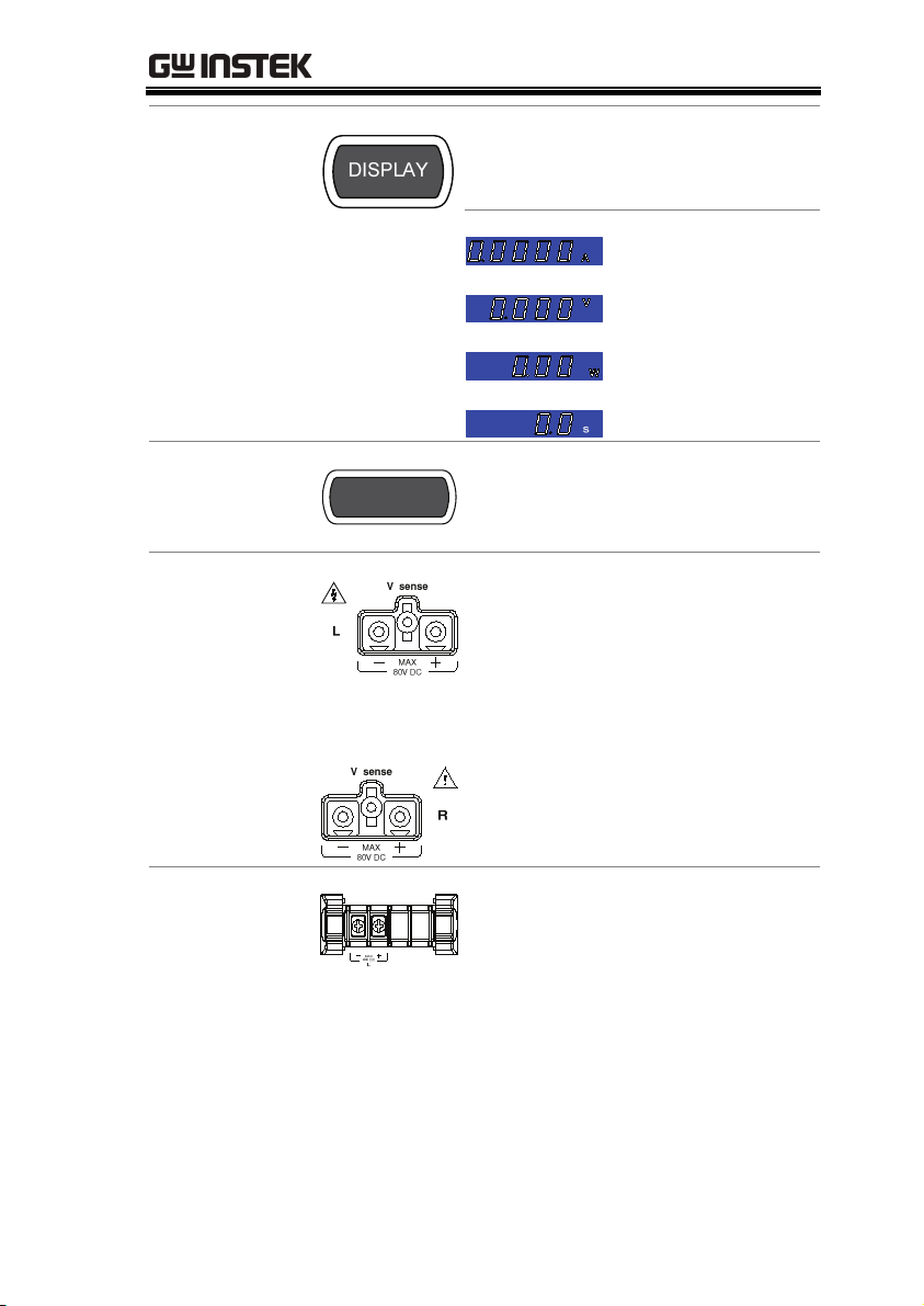
Display Key
Load Key
Left Voltage
Sense
Right Voltage
Sense
Used to alternate the display
output on the load module.
Current
Voltage
Power
Load time
LOAD
Activates the load for the active
channel. (Right or Left)(A or B)
The voltage sense terminals are
used when precise measurement is
needed. V Sense terminals are used
to compensate for voltage drops
across the main terminals caused
by the resistance of the load wires.
It is automatically activated when
connected to a DUT.
Positive and
Negative
Terminals Left
The terminals for both the left and
right side of a load can draw
differing amounts depending on
the load module specifications.
29
Page 30
PEL-2000 Series User Manual
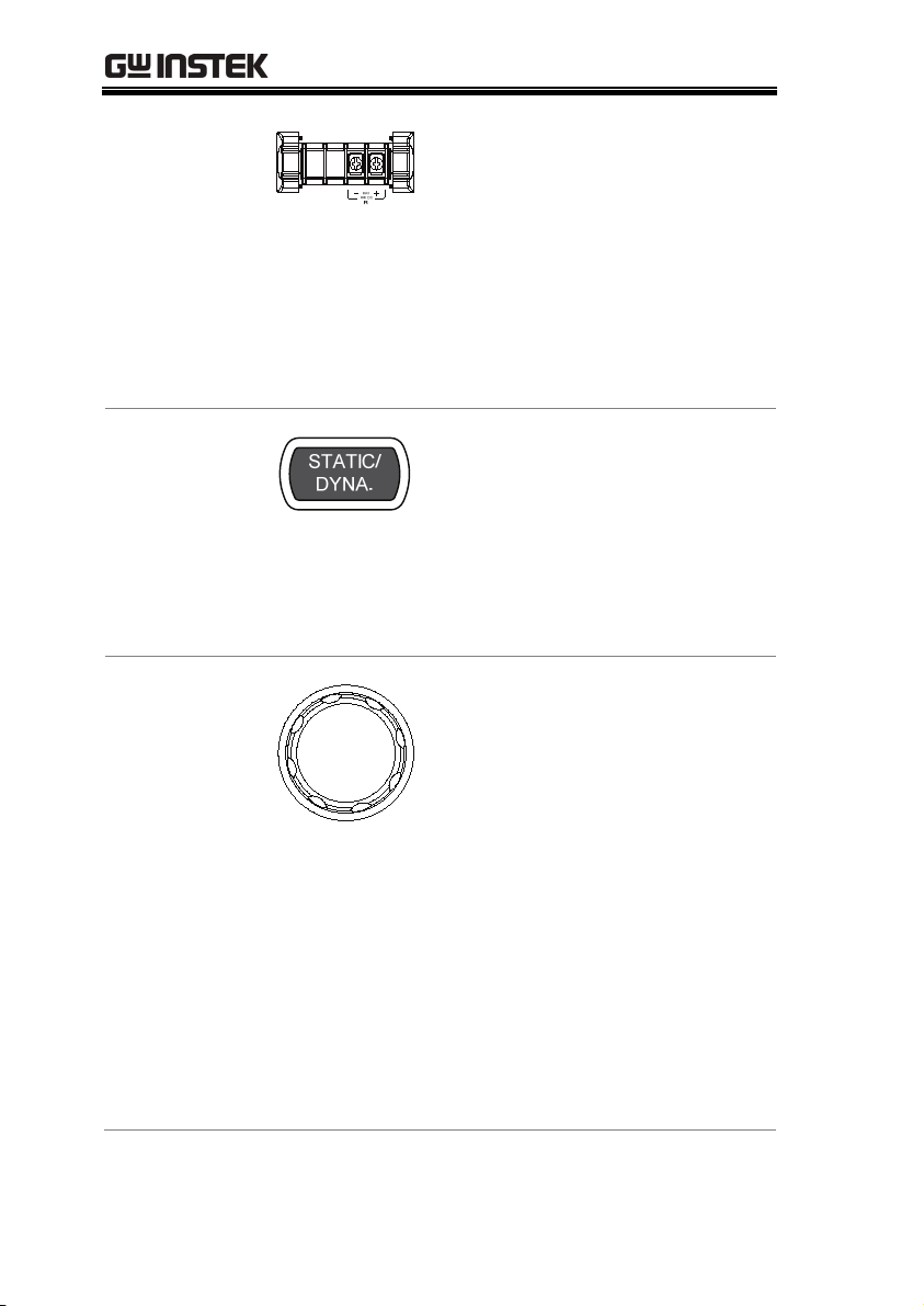
Positive and
Negative
Terminals Righ t
Static/Dynamic
Selector Key
Selector Knob
(Load)
For 2 channel load modules, the left
terminals are used for the 1
st
channel and the right terminals are
used for the 2
nd
channel.
On single channel load modules,
the left terminals are the lower (-)
potential terminals, whilst the right
terminals are the positive (+)
potential terminals.
The STATIC/DYNA. Key manually
switches the load from Static
(manual) to Dynamic loads.
Dynamic loads are only supported
in CC and CR mode.
For more information see page 61 &
65.
The load Selector Knob is used to
edit and vary parameters for the
active channel on the local load.
Depending on the Mainframe
setup, the Selector Knob will either
only update the load (locally) or
will update both the local module
and the mainframe*. The Selector
knob can also be configured to
display measured or set values on
the local load module**.
* For more information on “Knob Type”, see
page 188.
** For more information on “Slave Knob”,
see page 192.
30
Page 31

GETTING STARTED
Short Key
The SHORT key is used to
manually short circuit the active
channel on the local active load.
When a load is off, the SHORT key
will toggle the Short key type.
Load on: Pressing or holding the
SHORT key will short the load,
depending on the short type
selected.
Hold: Hold the
SHORT key to short
the channel load.
Toggle: Press the
SHORT key to
toggle shorting the
load on or off.
31
Page 32

PEL-2000 Series User Manual
LED Display Overview – Load Module
1&2. Channel
Display
3&7. Channel
Number Indicator
or
Left and right channel indicator.
5 digit display.
Indicates the channel number
(1-8).
Indicates if the load is active on
the load module. (Dual channel
load modules)
Indicates if the load is on for
single channel load modules.
32
Page 33

GETTING STARTED
4. Mode Indicator
The Mode Indicator LEDs will indicate what the
current mode or settings are on the active
channel(s).
or
Value A or B for a single channel load
module. Applies to CR, CV, and CC
static mode only.
Constant Current Mode (CC) mode
activated.
Constant Voltage Mode (CV) mode
activated.
Constant Resistance Mode (CR).
Display is shown on dual channel load
modules when both left (L) and right (R)
channel information is displayed.
Press the Display button repeatedly to
show information for both channels.
Lights up when Go/NoGo is activated
and the load passes (GO) the Go/NoGo
limits.
or
L or R will light up when the left or right
channel is selected.
Lights up when in Static mode.
Lights up when in Dynamic mode.
33
Page 34

PEL-2000 Series User Manual
Lights up when a load is shorted.
Lights up when Go/NoGo is activated
and the load fails (NG) the Go/NoGo
limits.
5&6. Channel
Unit Indicators
The Unit Indicators display current the
unit.
Voltage
Resistance
Current
Power
34
Page 35

GETTING STARTED
Installation
The installation chapter describes how to load the different load
modules, install the optional GPIB card, the rack mount kit and
how to determine each channel number.
Load Module Installation
WARNING
Module
installation
Steps
To avoid static electricity, please use appropriate antistatic work practices.
The PEL-2004 and 2002 can accommodate 4 and 2
load modules, respectively. Module loads can have
1 or 2 channels. Installation of load modules is the
same for both models.
1. Ensure the PEL mainframe is
turned off from the rear panel.
Disconnect the power cord.
2. Slide the module onto the rails of an empty
load slot.
35
Page 36

PEL-2000 Series User Manual
36
3. Use the supplied screw to fix the module to the
load slot, located under the load terminals.
4. Install any additional modules as described
above.
5. If there are any slots empty, install the
supplied panel cover (GW Instek part number:
63FP-AG106501). The panel cover will improve
safety and increase air flow.
Page 37

GETTING STARTED
6. Use the supplied screws to fix the panel
cover(s) over the load slot.
37
Page 38
PEL-2000 Series User Manual
GPIB Installation
WARNING
GPIB Card
installation
Steps
To avoid static electricity, please use appropriate antistatic work practices.
The PEL-2004 and 2002 has GPIB as an option (GW
Instek part no. PEL-001).
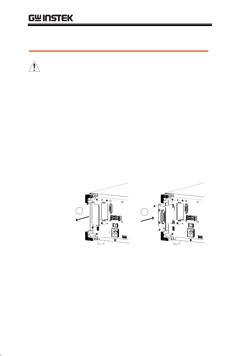
1. Ensure the mainframe is disconnected from
mains power.
2. Remove the screws from the GPIB cover plate
and remove the cover plate from the rear panel.
3. Slide the GPIB card into the slot and push
gently until the back plate is flush with the rear
panel.
1
2
4. Use the screws that were removed from step 1
to secure the GPIB card.
38
Page 39

GETTING STARTED
Rack Mount Installation
Background
Steps
PEL-2004
The PEL-2004 can be used in a standard 19” rack
mount enclosure with the optional rack mount kit
(GW Instek part no. 11EL-20040201). Each unit
requires a rack height of 4U with a 1U space for
ventilation top and bottom. The rear of the rack
mount enclosure must be free of obstruction to
allow heat to dissipate from the mainframe(s).
1. Screw the rack mount brackets as shown below
using the supplied bolts.
2. Insert into a standard 19” rack enclosure with
at least 1U of space top and bottom for
ventilation.
39
Page 40

PEL-2000 Series User Manual
Channel Number
Description
The channel number for a module load is
determined by which slot it occupies on the
mainframe chassis. There can be 1 or 2 channels
per slot, depending on the load module type.
The PEL2002 has two slots; The PEL-2004 has 4
slots. Channel 1 is the farthest away from the main
display panel and channel 8 (PEL2004) or channel
4 (PEL2002) is the closest to the main display
panel.
Below the PEL-2004 has all 4 slots occupied with
the PEL-2020, 2030, 2040 & 2041series load
modules (LM), respectively. The PEL-2020 & 2030
have 2 channels per load module, the PEL-2040 &
2041 have only 1. So the channel determination is:
LM1: CH1,CH2; LM2: CH3,CH4; LM3: CH5; LM4:
CH6.
DISPLAY
LOAD
V sense V sense
L
MAX
80VDC
80VDC
PEL-2020
STATIC/
DYNA.
SHORT
MAX MAX
L
DCElectronic Load
L
20A/80V ,100W
R
20A/80V ,100W
R
MAX
80VDC
80VDC
R
DC Electronic Load
5A/80V , 30W
L
40A/80V ,250W
R
PEL-2030
STATIC/
R/LR/L
DYNA.
DISPLAY
SHORT
LOAD
V senseV sense
L
R
MAX
MAX
80VDC
80VDC
MAXMAX
80VDC
80VDC
R
L
DCElectronic Load
PEL-2040
70A/80V ,350W
STATIC/
A/B
DYNA.
DISPLAY
SHORT
LOAD
V sense
MAX
80VDC
MAX
DC ElectronicLoad
PEL-2041
10A/500V ,350W
STATIC/
A/B
DYNA.
SHORT
DISPLAY
LOAD
V sense
MAX
500VDC
MAX
500VDC80VDC
PEL-2004
F2
F1
LOCAL UTILITY
FILEFUNC
CHAN
P9P7 P8
9
87
P6P4 P5
56
4
P3P1 P2
PRESET
3
1
2
CAL.
P0 LOCK
ENTER
CLEAR
0
DC ElectronicLoad
HELP
LOAD
F5F4F3
SHIFT
ON/
OFF
CH1
CH2
CH3
CH5 CH6
CH4
40
Page 41

GETTING STARTED
Power Up & Self Test
Panel operation
WARNING
1. Connect the power cord
to the power socket.
2. Turn the external power
switch on.
3. Hold the power button
on the front panel to
turn on the power.
The power button turns
green from red (standby).
Ensure that the power outlet has a ground socket. The
power outlet will have a ground connection if it is a 3
socket type.
Upon turning on, the Mainframe will perform a
self-test. The self-test checks the System, followed
by any attached channels.
41
Page 42

PEL-2000 Series User Manual
When the system check happens, the load modules
will display each channel as it is checked, then
display the current mode.
4. If any of the System checks fails, please power
down the load generator and reinstall the
appropriate load module(s).
5. To turn off the load
generator, hold the
power button for a few
seconds.
The PEL mainframe will
return to standby mode.
42
Page 43

GETTING STARTED
Load Connections
Precautions and Procedures
Intoduction
Wire Gauge
considerations
The PEL-2000 load generator supports a number of
different load configurations for flexible operation.
Single DUT, single load
Single DUT, parallel load
Multiple DUTs, multiple loads
Multiple DUTs, multiple mainframe loads
Single DUT, parallel mainframes
DC loads
Low voltage connections
The PEL-2000 also supports a number of different
control methods and interfaces. The connections
used are described here:
Frame link
Channel control
Go/NoGo
Before connecting the PEL-2000, wire gauge must
be taken into account. Load wires must be large
enough to resist overheating when a short-circuit
condition occurs as well as maintain a good
regulation. The size, polarity and length of a wire
are all factors in determining if a wire will
withstand short circuiting.
43
Page 44

PEL-2000 Series User Manual
Wire Selection
24 7.64
22 10.0
20 13.1
18 17.2
16 22.6
14 30.4
12 40.6
10 55.3
Load Line
Inductance
Considerations
Wires that are selected must be large enough to
withstand a short circuit and limit voltage drops to
no more than 2V per wire. Use the table below to
help make a suitable selection.
AWG Max Current A(Amp)
When using the PEL-2000 load generator, voltage
drop and voltage generated due to load line
inductance and current change must be taken into
account. Extreme changes in voltage may exceed
the minimum or maximum voltage limits.
Exceeding the maximum voltage limit may
damage the PEL-2000.
To determine the voltage generated, the following
equation can be used.
E = L x (∆ I / ∆ T)
E= voltage generated
L=load line inductance
∆ I= change of current (A)
∆ T= time (us)
Load line inductance (L) can be approximated as
1uH per 1 meter of wire. (∆ I / ∆ T) is the slew rate
in A/us.
44
Page 45

GETTING STARTED
The diagram above shows how changes in current can
affect voltage.
Limiting Load line
inductance
Load line inductance can be reduced by ensuring
load wires are as short as possible and by twisting
positive and negative load wires together. Current
change can be limited by limiting the slew rate
when switching.
“Twisted pair” will be shown on any connection
diagram where the load wires should be twisted
together.
45
Page 46

PEL-2000 Series User Manual
Load module
considerations
Connection
The PEL-2000 supports single and dual channel
load modules.
Single channel load modules have one bank of
negative terminals and one bank of positive
terminals. Each terminal pair has a 40A capacity.
For higher loads, each terminal can be wired in
parallel to increase capacity.
Dual channel load modules have one bank of
positive and negative terminals for each channel.
Single Channel Load
Module
Dual Channel Load
Module
Left channel
Right channel
MAX MAX
80V DC
80V DC
L
R
Follow the procedure below for all load
connections.
CAUTION
Steps
the DUT before making any connections.
1. Carefully lift the terminal covers.
2. Connect the positive (+) terminal on the load
module to the high potential output of the
DUT.
Ensure that power is off from the load generator and
3. Connect the negative (-) load terminal to the
low potential output of the DUT.
46
Page 47

GETTING STARTED
WARNING
CAUTION
4. Close the terminal cover securely. Ensure the
wires are secured properly and that the wires
are not exposed when the cover is in place.
Ensure that the wires are tied or twisted together to
prevent noise and inductance.
Ensure the polarity is correct before proceeding with
any connections. Using the wrong polarity could result
in reverse voltage damage.
DUT
Ensure the input voltage doesn’t exceed specifications.
Exceeding the voltage specifications could result in
damage to the instrument.
47
Page 48

PEL-2000 Series User Manual
Remote (Sense) Connection
Background
WARNING
Connection
The electronic load modules have two voltage
sense contacts: Vsense L(black), Vsense R(red).
Voltage sense can be used to help compensate for
long cable length. The longer the cable, the higher
the potential resistance and inductance, therefore a
short cable is best. Twisting the cable can help
reduce induced inductance and using the Vsense
terminals compensates the voltage drop seen
across the load leads, especially leads with higher
resistance. This is useful when used in CV or CR
mode.
VsenseR (red) must have a higher (+) potential than
VsenseL (black).
The diagram below shows how a DUT can be
connected using voltage sense. Note that the sense
wires are also twisted pairs.
Note
Input
smaller than 16 gauge.
The voltage sense terminals must use a wire gauge
of 16 to 14.
The wire gauge for the sense wires should be no
48
Page 49

GETTING STARTED
Remote Sense
Te rm i na l
connection
The voltage sense terminals use a screw-less clamp
connector. The clamp must be opened prior to
inserting a wire. Use a small screwdriver to push
the clamp release mechanism. Insert both wires
then release the clamp mechanism.
49
Page 50

PEL-2000 Series User Manual
Single Load Connections
Dual Channel
Load Module
Connection
Single Channel
Load Module
Connection
CAUTION
A dual channel load module can be used to sink
two loads concurrently.
On a single channel load module, the left terminals
are both negative (-), whilst the right terminals are
both positive (+). Note this also applies to the
voltage sense terminals.
For loads exceeding 40A, both positive and both
negative terminals must be used in parallel.
50
Page 51

GETTING STARTED
DC Connection
Low Voltage
Connection
For purely DC operation, a resistor and capacitor
can be connected in parallel to the electronic load
to reduce oscillation. The capacitor and resistor
values are dependent on the load settings. Ensure
the capacitor ripple current is within allowable
limits.
Using the load generator with low voltage loads is
generally limited to over 1 volt (load module
dependent). In order to support low voltage loads,
an auxiliary power supply is needed to boost the
voltage to a range suitable for the load generator.
Precautions:
Take into account the combined power of the
load and auxiliary power supply.
Make sure the auxiliary power supply is able
to provide enough current.
Take into account any noise or irregularities
from the auxiliary supply.
WARNING
The diagram below shows a typical connection.
Using an auxiliary power supply may induce reverse
current. The PEL-2000 series has reverse voltage
protection. For details see the protection section on
page 79.
51
Page 52

PEL-2000 Series User Manual
Parallel Load Connections
Parallel load
modules
Parallel load
When the power output of a DUT exceeds the
power rating of a channel or load module, the
channel terminals, load modules or mainframes
can be used in parallel to dissipate more power
when used in CC mode. Each channel will sink the
amount of current specified. The total power sunk
is the sum of all channels/modules. The amount of
power can vary from each channel. For example if
CH1 is 25A and CH2 is 20A, then the total current
sunk is 45A. Parallel loads are supported for both
static and dynamic loads (see page 78 for a
description on parallel dynamic loading).
-
Single Channel
Load Module
+
Single Channel
Load Module
DUT
-
-
+
+
-
Single Channel
Load Module
+
-
Single Channel
Load Module
+
Note
52
Please note that when using different load
modules in parallel, the slew rates may differ. See
the specifications for more details, page 253.
Page 53

GETTING STARTED
Parallel loads
using framelink
connections
Multi-output
power supply
load
The PEL-2000 mainframes can also be connected in
parallel. Please note, when using a frame link
connection there is a delay between the master and
the slave. Please see page 54 for details.
DUT
DUT
DUT
DUT
DUT
The PEL-2000 is also able to sink a number of loads
concurrently from multiple DUTs or sink a
number of loads from the same DUT (i.e. multiple
output power supply).
Master
Slave
Slave
Slave
Slave
Max 7kW
-
+
-
+
-
+
Multiple-output DUT
-
+
Twisted
Pair
Twisted
Pair
Twisted
Pair
Twisted
Pair
-
+
-
+
-
+
-
+
L
R
L
R
Dual channel
Load Module
Dual channel
Load Module
53
Page 54

PEL-2000 Series User Manual
Frame Link Connection
Background
Frame Link
Connection
Frame link control involves connecting multiple
mainframes using the frame link connections. Up
to 4 slave mainframes can be connected to the
master mainframe. The first mainframe (master)
can be used to control the other slave frames.
There is a delay time of 2ms between the master
and first slave mainframe, and 4ms, 6ms, and 8ms
to the second, third, and fourth slave mainframes,
respectively. The connectors used are standard
MIL 20-pin connectors. For pin arrangement see
page 236.
GPIB
GO/NG OUTPUT
RS232C
Master
(FRM)
RS232C
Slave
(FRS)
WARNING
TOAVOID ELECTRICSHOCK THEPOWER CORDPROTECTIVE
GROUNDINGCONDUCTORMUSTBE CONNECTEDTOGROUND.
FORCONTINU EDFIRE PROTECTION. REPLACE FUSEONL YWITH
250VFUSEOF THESPECIFIEDTYPEAND RATING.
NOOPERATOR SERVICEABLECOMPONENTS INSIDE.
DONOT REMOVE COVERS. REFERSER VICINGTO QUALIFIE DPERSONNEL .
GPIB
WARNING
TOAVOID ELECTRICSHOCK THEPOWER CORDPROTECTIVE
GROUNDINGCONDUCTORMUSTBE CONNECTEDTOGROUND.
FORCONTINU EDFIRE PROTECTION. REPLACE FUSEONL YWITH
250VFUSEOF THESPECIFIEDTYPEAND RATING.
NOOPERATOR SERVICEABLECOMPONENTS INSIDE.
DONOT REMOVE COVERS. REFERSER VICINGTO QUALIFIE DPERSONNEL .
REPLACEFUSE
REPLACEFUSE
ASSPECIFIED
FUSERATING
115V
230V
GO/NG OUTPUT
ASSPECIFIED
FUSERATING
115V
230V
SER.NO. LB
FRAME CONT
1
2
AC
T3.15A
180V AMAX
250V
50/60Hz
DISCONNECTPO WERCORD
BEFOREREPLAC INGFUSE
SER.NO. LB
FRAME CONT
1
2
AC
T3.15A
180V AMAX
250V
50/60Hz
DISCONNECTPO WERCORD
BEFOREREPLAC INGFUSE
FRAME CONT
1
2
STRIP GAUGE
10.0mm
AWG24
STRIP GAUGE
10.0mm
AWG24
Output
CH CONT11CH CONT21CHC ONT31CH CONT4
1
Input
Output
CH CONT11CH CONT21CHC ONT31CH CONT4
1
2
CH CONT51CHCO NT61CH CONT71CHC ONT8
1
1
FRAME CONT
1
2
2
CH CONT51CHCO NT61CH CONT71CHC ONT8
1
GPIB
GO/NG OUTPUT
RS232C
Slave
(FRS)
REPLACEFUSE
ASSPECIFIED
FUSERATING
115V
230V
WARNING
TOAVOID ELECTRICSHOCK THEPOWER CORDPROTECTIVE
GROUNDINGCONDUCTORMUSTBE CONNECTEDTOGROUND.
FORCONTINU EDFIRE PROTECTION. REPLACE FUSEONL YWITH
250VFUSEOF THESPECIFIEDTYPEAND RATING.
NOOPERATOR SERVICEABLECOMPONENTS INSIDE.
DONOT REMOVE COVERS. REFERSER VICINGTO QUALIFIE DPERSONNEL .
SER.NO. LB
FRAME CONT
1
2
AC
T3.15A
180V AMAX
250V
50/60Hz
DISCONNECTPO WERCORD
BEFOREREPLAC INGFUSE
1
FRAME CONT
1
2
CH CONT51CHCO NT61CH CONT71CHC ONT8
1
Input
STRIP GAUGE
10.0mm
AWG24
CH CONT11CH CONT21CHC ONT31CH CONT4
1
54
Page 55

GETTING STARTED
Insertion
Removal
The first mainframe that is connected is the master
frame; any additional frames are slave units. The
ribbon cable connects to the master from connector
2, and the slave from connector 1. Each successive
slave unit is connected in a cascading manner the
same way.
Ensure the Mainframes are turned off before
connecting the ribbon cables. Push the cable into
the frame link connector. Ensure the arrows line
up. The latches will close when the connection is
complete. To remove, pull the latches out and
connector will come out.
WARNING
Ensure all the mainframes are off and disconnected
from mains power before connecting.
55
Page 56
PEL-2000 Series User Manual
Channel Control Connection
Background
The Channel Control connecters are located on the
rear panel of each mainframe. There are two
channel control connectors for each load slot, one
for each channel, if applicable. The channel control
connector is used to externally:
Turn on/off loads.
Supply a reference voltage.
Monitor the load input.
For further details on channel control and the
interface see pages 85, 235.
GPIB
GO/ NGOUTPUT
RS232C
TOAVOID ELECTRICSHOCK THEPOWER CORDPROTECTIVE
GROUNDINGCONDUCTORMUST BECONNECTEDTO GROUND.
FORCONTINUED FIRE PROTECTION.R EPLACE FUSEON LYWITH
250VFUSE OFTHE SPECIFIEDTYPE ANDRATING.
NOOPERATOR SERVICEABLECOMPONENTS INSIDE.
DONOT REMOVECOVERS. REFERSERVICING TOQUALIFIED PERSONNEL.
WARNING
REPLACEFUSE
ASSPECIFIED
FUSERATING
115V
230V
T3.15A
1
2
250V
SER.NO. LB
FRAME CONT
DISCONNECT POWERCORD
BEFOREREP LACINGFUSE
AC
180 VAMAX
50/60Hz
CH CONT8
1
CH CONT7
1
CH CONT6
1
CH CONT5
1
STRIPGAUGE
CH CONT4
10.0mm
AWG 24
1
CH CONT3
1
CH CONT2
1
CH CONT1
1
The Channel Control input/output pin layout is shown
below.
56
Page 57

GETTING STARTED
External Voltage
Connection
WARNING
Load on
connection
The external voltage reference input must be
between 0~10V.
Ensure the external voltage reference is stable and has
low noise. The External Voltage should be no more
than 10V.
No more than 12 volts may be used as an external
voltage. More than 12 volts may damage the load
generator.
To turn a load on, an active low voltage (0-1V)
must be applied across Load On (pin 5) and GND
(pin 1), similarly an active high voltage (4-5V)
must be applied to turn a load off. The Load On
input must be TTL.
57
Page 58

PEL-2000 Series User Manual
Voltage and
Current Monitor
Output
Connector
Connection
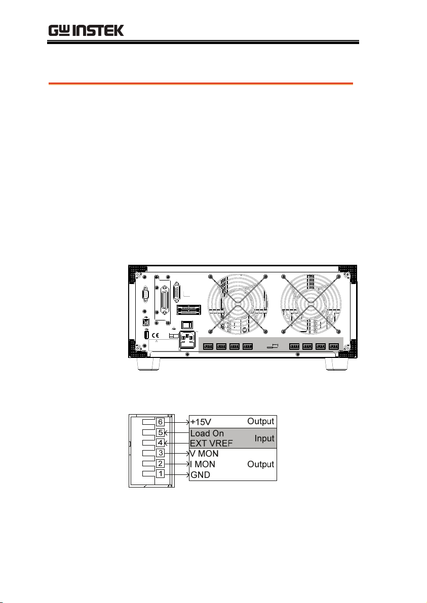
The Voltage Monitor Output (VMON) and Current
Monitor Output (IMON) output the load input
voltage and load input current as a percentage of
rating current/voltage. Where 0 volts = 0% rating
and 10 volts = 100% load input rating voltage or
current.
The voltage monitor output is across pins 1 & 3,
and the current monitor output is across pins 1 &
2. Pin 6 outputs a +15V reference voltage.
Below shows the pin configuration of the voltage
and current monitor outputs.
The channel control connector is a screw less
clamp connector. The internal clamp mechanism
must be opened before a wire can be inserted. To
open the internal clamp, push the button above the
wire socket, to close, release the button. Ensure at
least 10mm is striped from the wire. The diagram
below shows the wire insertion procedure.
All connections to the channel control connector must
WARNING
use a 24 AWG wire gauge.
58
Page 59

GETTING STARTED
Go/NoGo Connection
Background
The Go/NoGo port is a 15 socket port. Each
channel has a dedicated line for a Go/NoGo
output. The ports are open-collector with active
low (1.1V) indicating a pass and active high (30V)
as fail (an alarm). The Go/NoGo terminal is a DB15 female.
For more details on the Go/NoGo interface see
page 239.
59
Page 60

PEL-2000 Series User Manual
OPERATING
DESCRIPTION
Operating Mode Description ........................................... 61
Constant Current Mode ........................ 61
Constant Resistance Mode ................... 65
Constant Voltage Mode ........................ 68
Run Program ................................................................... 71
Sequence ........................................................................ 74
Parallel Dynamic Loading ................................................ 78
Configurations Description.............................................. 79
Protection Modes ................................. 79
Operating Configurations ..................... 81
Channel Control ................................... 85
Interface and File System ................................................ 89
Interface .............................................. 89
File System .......................................... 89
File Format .......................................... 94
60
Page 61

GETTING STARTED
Operating Mode Description
There are three basic operating modes: constant current (CC),
Constant Resistance (CR), and Constant Voltage (CV/CV+CC). All
channels operate using any of the modes. Each mode has a number
of configurable options including slew rate, levels, protection
modes, Go/NoGo and extensive save options.
Constant Current Mode
Background
In Constant Current Mode the load units will sink
the amount of current programmed. Regardless of
the voltage, the current will stay the same. There
are two ranges in CC mode: High and Low. There
are two main modes in CC mode: Static and
Dynamic. Static mode can be used for stability tests
and dynamic mode can be used to test transient
load conditions.
Go/NoGo is supported for both High and Low
range as well as Static and Dynamic mode.
CC Mode
Load Current
Load Input Voltage
61
Page 62
PEL-2000 Series User Manual
Range
Static Functions
Static Mode:
Single Channel
Load module.
There are two selectable ranges for constant current
mode: high and low range.
Low range has a higher resolution, but a lower
range. If the current exceeds the Low Range, High
range must be used.
Static mode tests the stability of the voltage output
from a power source. Single channel load modules
can have two 2 current levels A (A Vaue) & B (B
Value). A & B have the same range. Pressing the
A/B key on the module load will cycle through the
A and B states. Alternatively, the mainframe can
select A or B Value.
Dual channel load modules only have one current
level (A Value) per channel in static mode.
Dynamic
Functions
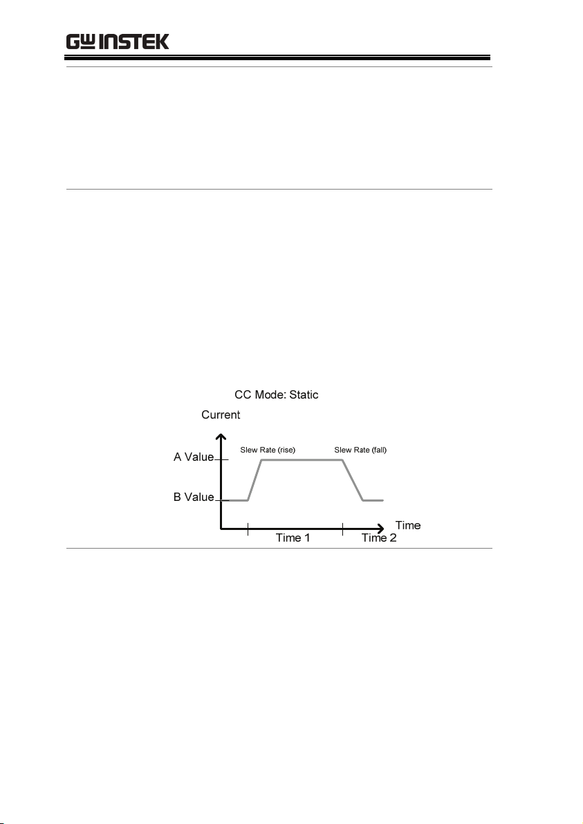
Dynamic load functions allow you to set load
levels (Level1, Level2), load time (Timer1, Timer2),
and the slew rate (rising, falling). Depending on
the settings, the load will switch automatically
between levels 1 and 2.
Dynamic loading can be used for charge discharge
cycle testing etc.
62
Page 63

GETTING STARTED
Slew rate
Go/NoGo
The slew rate is the rate at which the current will
increase to a set level. There are two slew rates:
rising slew rate & falling slew rate. In CC mode the
slew rate is defined as A/uS.
As can be seen above, the rising and falling slew
rate need not be the same.
Using Go/NoGo, the Center, High and Low
voltage limits can be set for both Static and
Dynamic modes. A delay time of up to 1 second
can also be set.
63
Page 64

PEL-2000 Series User Manual
CC Mode: Static:Go/NoGo
Current
Load
Current
Low
Go
High
NoGoNoGo
Voltage
GO is specified as between the Low and High
Go/NoGo limits. NoGo is specified as outside the
Go/NoGo limits.
64
Page 65

GETTING STARTED
Constant Resistance Mode
Background
Resistance Range
In Constant Resistance Mode the load units will
linearly sink current and voltage to match a set
resistance. CR mode has two different values
(single load modules), two different ranges and
rising and falling slew rates. Like CC mode,
Constant resistance mode supports both dynamic
and static loads. As with the other modes,
Go/NoGo is supported.
CR Mode
Load Input
Voltage
R
Load Current
e
c
n
a
t
s
i
s
e
There are two ranges: High and Low. The Low
range is used for low voltage ranges, whilst the
High range uses high voltage ranges. The current
range always remains in High range, regardless of
the selected voltage range.
Static Functions
A/B range
For static mode, single channel load modules have
two resistance levels, A & B Value. The A/B key
can be used to switch between these resistance
levels. Dual channel load modules only have one
resistance level, A Value.
65
Page 66

Single Load
Module
PEL-2000 Series User Manual
Dynamic
Functions
Slew Rate
Go/NoGo
CR mode supports Dynamic loading. Dynamic
load has two resistance levels (Level 1&2), and two
timers (Timer 1&2) to switch between the
resistance levels. Rising and falling slew rates can
be set to determine the speed at which the load
generator switches between load levels.
The rising and falling slew rate (A/uS) determines
the speed at which the load levels change from A
to B Value (Static mode) or from Level1 to 2
(Dynamic mode) and vice versa.
Go/NoGo is also supported. Center, High and
Low limits can be set as either percentages or
voltage values. A delay time of up to 1 second can
also be set.
66
Page 67

GETTING STARTED
67
Page 68

PEL-2000 Series User Manual
Constant Voltage Mode
Background
In Constant Voltage Mode the load units will sink
current whilst keeping the voltage constant.
Single channel load modules support 2 values (A
Value, B Value) and have an adjustable cut-off
current limit. Dual channel load modules only
have A value.
Response speed can also be set to fast (Fast) or slow
(Slow). The response speed relates to the slew rate
of the current response.
Constant voltage mode only operates in high
range.
Go/NoGo functionality is also supported either as
a percentage or as a current value.
Voltage levels
Two voltage levels can be set: A & B (single
channel load module).
68
Page 69

GETTING STARTED
CV + CC
Voltage
A value
B value
CV Mode
Time
When using CV mode, a current limit can be set for
CV + CC mode.
When the voltage input is greater than A Value
(load voltage) then the channel will operate in CV
mode if the input current is less than the current
limit. When the input current exceeds the current
limit, the channel will operate in CC mode.
When the voltage input is less than A Value (load
voltage) current stops flowing.
69
Page 70

PEL-2000 Series User Manual
Response Speed
Go/NoGo
Response speed can be set to fast or slow. Fast
response and slow response is determined by the
load module specifications. Slow response speeds
are suitable for large loads as quick current
changes will induce induction which can cause
large voltage drops. The PEL series will try to
rectify any voltage drops. However if voltage
drops are too large, they may cause the load
generator to go into oscillation. Large voltage
drops caused by line voltage induction may
damage the machine.
Range Fast Slow
1kHz 100Hz
Go/NoGo testing can be with either current
(Ampere) values (High, Low) or percentage values
(Center, High %, Low %). A delay time of up to 1
second can also be set.
70
Page 71

GETTING STARTED
Run Program
Background
Program
Sequence
The Program function on the PEL-2000 series
supports a total of 12 different programs at any one
time with 10 sequences to each program. Up to 12
programs can be chained together. The Program
function is able to create a number of Go/NoGo
tests.
A program sequence is simply a single load test. A
program is a battery of each of these tests run in
succession. Each sequence loads the settings for
each channel from Memory Data (Memory MXXX).
The Memory Data stores settings such as the
operating mode and range for each channel. Each
sequence loads all channels at the same time, unless
programmed otherwise. Sequences for each
channel run synchronously.
Memory M001~M120
On-Time 0.1 ~ 60.0
Short-time Off – 0.1 ~ On-time
Each Sequence has a number of configuration
options that apply to all the channels equally.
Sequence Item Parameter Range
Run Auto – Skip – Manual
Off-Time Off – 0.1 ~ 60.0
71
Page 72

PEL-2000 Series User Manual
y
P/F-Time Off – 0.1 ~ (On-time+Off-time)-0.1
Short Channel CH1 ~ CH8
Program
Sequences are run sequentiall
There are 10 Sequences in each Program.
If less than 10 Sequences are desired for a Program,
any additional Sequences can be skipped (not run).
Sequence 2 & 3 are skipped.
Program Chain
Any of the 12 programs can be chained together to
create a Program Chain. Unlike Program
Sequences, Program Chains need not be run
sequentially in numerical order. Any program can
be chained to any program. It is possible to chain
programs into an infinite loop to continue a
program indefinitely.
to create a Program.
Above, a program chain running sequences out-oforder.
72
Page 73

GETTING STARTED
Go/NoGo Results
If Go/NoGo limits have been configured, the
Pass/Fail results for each channel will be displayed
for all the sequences and programs.
73
Page 74

Sequence
PEL-2000 Series User Manual
Background
Load Profiling
The Sequence function is used to create high
resolution load simulations. Each Sequence can be
configured to create a unique load profile to
accurately simulate loads in real time. Sequences
are only applicable for CC (Static) and CR (Static)
modes.
Note: Sequences are not to be confused with the
sequences used to create a program. They are not
the same and cannot be used interchangeably.
Sequences (SEQ memory) cannot be used in
Programs and Programs cannot load Sequences.
The Sequence function is able to simulate a load to
a high resolution. Each channel is able to change its
load sink within 100us per point independently.
When used in parallel, multiple loads can be sunk
concurrently to simulate the loads placed on
multiple output power sources.
The diagram below shows the load profile of a
DUT at start-up.
74
Page 75

GETTING STARTED
Points
Loop
Up to 120 points can be used with each Sequence.
Each point can have a different duration, slew rate
and value.
A new point can be inserted or deleted at any stage
of a Sequence. Any new points that are inserted
will have a value averaged from its neighbors as
default.
Point1
Point2
Point4
Point5
Point6
Point3
Point7
A new point is inserted after Point 3.
Sequences can be programmed to loop a number
of times starting from any point in the sequence.
Point1
Point2
Point4
Point3
From Point3 the sequence is looped two times.
75
Page 76

PEL-2000 Series User Manual
On end load
Trig Out
If more than one Sequence is programmed on the
mainframe, the On End Load function allows a
Sequence to configure its load on or off at the end
of its sequence until the last sequence ends. After
the last sequence ends, all loads are turned off.
This function is ineffective if only one Sequence is
active. This is as the On End Load time and the
time of the last sequence will be the same.
End of
Sequences
The Trigger Out function allows a trigger sequence
signal to be output from a channel via PIN 4 on
Frame Link connector 1 when using Sequences.
The Trig Out function is used from the Channel
Duration menu.
Point1
Point2
Point3
Point4
Point5
Point6
As can be seen above, a trigger sequence signal is
output for every rising edge point.
76
Page 77

GETTING STARTED
Channel Duration
Time Setting
The Channel Duration Time Setting feature allows
the point time duration of one Sequence to be
imported by another Sequence. If the receiving
sequence doesn’t have enough points, more will be
created (without values).
For example, the sequences for CH1 and CH2 are
shown below. CH1 has a total of 6 points with long
durations, whilst CH2 has only 2 points, looped 5
times. The points from CH2 are also significantly
shorter in duration.
Point1
Point2
Point3
Point4
Point5
Point6
Point2
Point1
Below shows the resulting sequence when CH1
imports CH2. CH1 imports the duration time
settings and number of points from CH2, but not
the value data.
77
Page 78

PEL-2000 Series User Manual
Parallel Dynamic Loading
Background
The PEL-2000 series of DC electronic loads support
parallel dynamic loading. This simply means that
when the load modules of a mainframe are
connected in parallel and set to dynamic mode,
they can perform dynamic tests synchronously
following the same clock. Under dynamic mode,
load current or resistance is pulsed between two
preset levels. When used in parallel, higher
powered outputs can be tested. This ability gives
the PEL-2000 series the flexibility to perform
dynamic tests over a wide range or power outputs.
For connection details see the Parallel Load
Connections section on page 52.
The diagram below shows how two load modules
are able to sink a higher load when used in parallel
under dynamic mode.
78
Page 79

GETTING STARTED
Configurations Description
There are a number of different configurations for the PEL series
including protection modes, operating configurations, and file
system configurations. The Configuration Description section
describes what the different configurations are used for and how
they can be relevant to different operations.
Protection Modes
Background
The PEL 2000 series include a number of protection
modes: Over Current Protection, Over Voltage
Protection and Over Power Protection.
The protection modes are useful to protect both the
load modules and the DUT(s). A buzzer can be set
to notify when a protection setting has been
tripped. When a protection feature is activated and
has been tripped then the load unit will display an
alarm. The Mainframe will also display an alarm.
When an alarm has been tripped the load will stop
sinking current/voltage. There are three Over load
protection settings: ON, OFF and Clear.
03/02/09
10 : 30
Alarm
CH1
CC
Dyna
High
Conf
Protection
Other
Go-NoGo
Previous
Configure
Menu
79
Page 80

PEL-2000 Series User Manual
Over Current
Protection
OCP level
Over Voltage
Protection
When a load unit is operating in CR or CV mode,
the unit may need over current protection to
prevent excessive current being sunk. Over current
protection stops the load from sinking more current
than its recommended limit which can cause
damage to the unit.
CV Mode: OCP
I
V
CR Mode: OCP
V
e
c
n
a
t
s
i
s
e
R
OCP level
Over voltage protection is used to limit the amount
of voltage sunk. If the OVP trips, the PEL series
load will stop sinking voltage.
CC Mode: OVP
Load Current
I
Load Input Voltage
Over Power
Protection
Over power protection is used when the power
range exceeds the specifications of the load. When
OPP is tripped power will cease to be sunk.
80
Page 81

GETTING STARTED
Reverse voltage
Protection
Reverse voltage protection prevents reverse voltage
damage to the PEL-2000 series up to the specified
rating. When Reverse voltage protection has been
tripped an alarm tone will sound until the reverse
voltage is removed.
For more details please see the specifications.
Under voltage
Protection
Under voltage protection will turn off the load
when the voltage drops below a set limit.
Operating Configurations
Background
CC Vrange
There are number of operating configuration
settings. Configuration settings are for the
following:
CC Vrange, Von Voltage, Von Latch, Short Key, CH
Cont, Independent load sync, D-time and Step
resolution settings.
CC Vrange (page 165) is used to set the voltage
range as High or Low for CC mode. CC voltage
range is dependent on the load module
specifications.
81
Page 82

PEL-2000 Series User Manual
Von Voltage
Von Voltage is the voltage limit at which the load
will start to sink current. There are two operation
modes for Von Voltage: Von latched:ON and Von
latched:OFF.
Latched: ON will sink current when Von has been
tripped, and will continue to sink current even if
the voltage drops below the Von Voltage.
Von Latched: OFF will sink current when Von has
been tripped, but will stop sinking current when
the voltage drops below the Von Voltage setting.
As can be seen in the diagram below, when Von-Latch
is set to off, the load module will start to sink current
when the Von-voltage limit has been tripped. It will
stop sinking current when the output drops below the
Von voltage limit.
82
Page 83

GETTING STARTED
Short
Note
CH CONT
When short mode is on, the load unit can simulate a
short circuit.
Shorting can be individually set for each channel
when programming sequences.
To initiate a short circuit manually, the short key is
used. It can be used at any time during an
operation. It will not affect the settings. After a
short circuit has finished, the load unit will resume
the previous operation.
The short key can be set to toggle or hold. When
pressed in toggle mode, shorts are toggled on and
off. When pressed in hold mode, the key needs to
be held to short the load.
A short circuit may trip a protection mode if too much
current is sunk.
Channel Control. When Channel control is
activated (External) it can be used to monitor the
voltage and current output of the load as well as
turn loads on or off remotely from the Channel
Control (CH CONT) connectors located on the rear
panel.
Independent
For more information about channel control, see
external voltage control on page 85.
The Independent setting will allow the load
modules to be controlled independently from the
mainframe.
83
Page 84

PEL-2000 Series User Manual
Load D-Time
Step Resolution
Load Delay time is used to delay activating a load
(up to 10 seconds) after the load key has been
pressed. However the Load D-Time setting will
only work for loads that are initiated manually or
when the PEL series mainframe is configured to
Auto load (page 182) at run time.
Each channel voltage, current and resistance setting
can have the step resolution configured.
For example if the step resolution for CCH (CC
high range) is .5 A, then the resolution can be
incremented in .5A steps;
8.08.59.09.5
The step resolution parameters apply to the
following:
CCH Step – CC high range
CCL Step – CC low range
CRH Step – CR high range
CRL Step – CR low range
CV Step – CV high range
Step Resolution
Range
84
The step resolution range is dependent on the load
module and the range:
Max resolution: channel range/4000
Min resolution: channel range/2
Page 85

GETTING STARTED
Channel Control
Background
External Voltage
Reference
External channel control is used with the Channel
Control connectors. Each channel control connector
can activate each load, monitor voltage and current
and has an external voltage reference input. The
voltage and current monitors output 0~100% of the
rated current/voltage as a voltage of 0~10V.
GPIB
GO/ NGOUTPUT
RS232C
TOAVOIDELECTRIC SHOCKTHEPOWER CORDPROTECTIVE
GROUNDINGCONDUCTOR MUSTBE CONNECTED TOGROUND.
FORCONTINUED FIRE PROTECTION.REPLACE FUSE ONLYWITH
250VFUSE OF THESPECIFIED TYPE ANDRATING.
NOOPERATOR SERVICEABLECOMPONENTSINSIDE.
DONOT REMOVECOVERS. REFERSERVICINGTO QUALIFIEDPERSONNEL.
WARNING
REPLACEFUSE
SER.NO. LB
FRAME CONT
1
2
ASSPECIFIED
AC
FUSERATING
115V
T3.15A
180 VAMAX
250V
230V
DISCONNECT POWER CORD
BEFOREREPLACING FUSE
50/60Hz
CH CONT51CH CONT61CH CONT71CH CONT8
STRIPGAUGE
10.0mm
AWG24
1
CH CONT11CH CONT21CH CONT31CH CONT4
1
A voltage reference of 0-10V is used to represent 0100% of the rating voltage/current of a load
module. As seen below the external voltage
reference and the rating voltage/current have a
linear relationship. By varying the reference voltage
between 0~10V the voltage/current setting will be
changed accordingly.
85
Page 86

PEL-2000 Series User Manual
Current Monitor
To determine the Percent Rating (voltage or current
load input), use the following formula;
InputLoad
Where “Rating Vor A” is the rating voltage/current
of the load module.
The load current input can be externally monitored
using the IMON pin of a channel control connector.
The IMON pin outputs a voltage of 0~10V to
represent the input current of as percentage
(0~100%) of rating current.
10
VoltageExternal
V
VorARating
To determine the Current Monitor Output
(IMON) , use the following formula;
IMON 10
currentinputLoad
V
ARating
Where “Rating A” is the rating current of the load
module.
86
Page 87

GETTING STARTED
Voltage Monitor
The input voltage, like the load input current can be
externally monitored with the channel control
connectors. The VMON pin of the channel control
connector outputs a voltage of 0~10V to represent
the load input voltage as a percentage (0~100%) of
the rating voltage.
To determine the Voltage Monitor Output
(VMON) , use the following formula;
VMON 10
voltageinputLoad
V
VRating
Where “Rating V” is the rating voltage of the load
module.
87
Page 88

PEL-2000 Series User Manual
Turning on the
Load
A load is turned on when Load On input is set to
On (active low). A load is turned off when the Load
On input is set to Off (active high).
When a load is turned on from the channel control
interface, the load can be turned off from the
mainframe, local module and via remote control.
However the opposite is not true; when a load is
turned off using the channel control interface, the
load cannot be turned on via the mainframe, local
module or via remote control.
For connections and configurations, see pages 56
and 235 respectively.
88
Page 89

GETTING STARTED
Interface and File System
Interface
Background
RS-232 configuration. Page 196
RS-232 pin connection. Page 233
GPIB configuration. Page 198
GPIB pin configuration. Page 234
USB configuration. Page 199
The PEL series support RS232, GPIB and USB
remote frame control. Only one type of connection
is supported at any one time. For more information
on remote control please see the GW Instek
website at www.gwinstek.com
distributor about the PEL-2000 programming
manual.
For connection options and configurations see the
options below.
or see your local
File System
Background
The PEL series is able to save and recall a number
of different data types for each channel:
Presets
Memory
Setup
SEQ (Sequence)
All data types can be saved and recalled to internal
memory or saved to a USB flash drive. Each
channel has its own dedicated memory for each
89
Page 90

PEL-2000 Series User Manual
data type. Thus files are saved/recalled for each
channel and each data type.
Preset Data
Preset data can be saved into 10 memory slots for
each channel. Preset data contains the mode,
range, CV response speed and Go/NoGo settings.
Internal Format
External Format
P0~P9
20X0X_XX.P
Preset Contents Preset data contains the following data;
Memory Data
CHAN Mode
Range
Go/NoGo SPEC Test
High
Center
Each channel can save up to 120 different Memory
Static/Dynamic
CV response
Entry Mode
Low
data types (M001~M120) into internal memory.
Memory data contains general channel settings
and is used when programming sequences.
Memory
data can be stored both internally and
externally to USB. Preset data and Memory data
store the same contents.
speed
Internal Format
External Format
M001~M120
20X0X_XX.M
Memory Contents Memory data contains the following data;
90
CHAN Mode
Range
Go/NoGo SPEC Test
High
Center
Static/Dynamic
CV response
speed
Entry Mode
Low
Page 91

GETTING STARTED
SEQ Data
SEQ data contains Sequence data. SEQ data can
only be saved to and from USB. SEQ refers to
Sequence data, not Program sequences.
Internal Format
External Format
N/A (Internal buffer)
20X0X_XX.A
SEQ Contents SEQ data contains the following data;
Setup Data
Seq.Edit No. (Points)
Slewrate
Duration time
Loop Repeat
On End Load
Setup data can be saved to 4 internal memory slots.
Value
Slewrate
Start of Loop
CC Vrange
Setup data contains Memory data, Program
Sequence, Chain data, configuration settings and
operation settings for every channel. Setup data
can be saved to Internal memory or to USB.
Internal Format
External Format
Setup Memory 1~4
200X0_XX.S
Setup Contents Setup data contains the following data;
Program PROG
Memory
On-Time
P/F-Time
Short Channel
Chain Start
SEQ (program
Run
Off-Time
Short-Time
Program
sequence no.)
Sequence
(P01~P12)
91
Page 92

PEL-2000 Series User Manual
─
─
─
Save: Internal
memory
Save: External
memory
Run
CHAN Mode
Go/NoGo SPEC Test
Active Channel
(CH01~08)
Range
High
Center
Static/Dynamic
CV response
speed
Entry Mode
Low
When saving data to internal memory, either the
current channel or all the channel data can be
saved. Not all data types can save the current
channel or all the channel data.
Data Type Current Ch All Ch
Preset • •
Memory •
SEQ • (single save) •
Setup
•
Only SEQ, Memory and Preset data can be saved
for a single channel to USB. All four data types
(SEQ, Memory, Setup, Preset) can save all channels
to USB.
Data Type Current Ch All Ch
Preset • •
Memory • •
SEQ • •
Setup
92
•
Page 93

GETTING STARTED
Save/Recall USB
In order to save data from a single channel to USB,
data must first be saved to the internal memory.
After data is saved to internal memory, all the files
can be saved to USB.
To recall saved files, the reverse is also true. Files
must be recalled from the USB flash drive to
internal memory. Then from internal memory the
data can be recalled to each channel*.
*Excluding SEQ data.
Save/Recall All
The SEQ, Preset, Memory or Setup data can be
saved from every channel into USB. SEQ, Preset
and Memory data is saved into a directory
(ALL0000-ALL0099) with a file for each channel,
whilst Setup data is saved in a single file.
93
Page 94

PEL-2000 Series User Manual
To recall saved files, the reverse is not true. Files
must be recalled to each channel separately.
File Format
Single Channel Filename format
Memory data
Preset data
SEQ data
1: PEL series Load module
type:
2020 = PEL-2020
2030 = PEL-2030
2040 = PEL-2040
2: Channel
R = Right
L = Left
0 = Single channel or
not used
3: Save file number:
0 ~99
Incremented after each
consecutive save.
4: File extension
94
M = Memory data
P = Preset data
A= SEQ data
Page 95

GETTING STARTED
All Channel Directory Format
All Channel File Format
Memory data
Preset data
SEQ data
Setup Data
1: All Channel common
directory name
2: Directory number:
0000 ~ 0099
1: PEL series Load module
type:
P020 = 2020
P030 = 2030
P040 = 2040
2: Channel
R = Right
L = Left
0 = Single channel
3: Channel number:
C1 = CH1
C2 = CH2
Etc.
00 = All channels
(Setup data)
4: File extension
M = Memory data
P = Preset data
A= SEQ data
S= Setup data
95
Page 96

PEL-2000 Series User Manual
TUTORIALS
(Step by Step Operations)
Local loads ...................................................................... 97
Single Channel Load ........................................................ 99
Programming ................................................................. 101
Sequences ...................................................................... 103
Frame Link ..................................................................... 104
Channel Control ............................................................. 106
General Configuration Options ....................................... 108
96
Page 97

TUTORIALS
Local loads
Local mode operation is useful to quickly test loads using the load
module control panel rather than the mainframe control panel.
Local load modules can be configured to operate independently to
the mainframe. This can be useful when settings need to remain
unchanged on the mainframe. Note however that the local modules
cannot change the modes (CC, CV, CR), only the values.
Step Description Details
1. Setup
2. Channel
selection
3. Measurement
Mode
selection
4. Run the Load
Optional
5. Short
configuration
6. Display
Ensure the channel load is set up
as desired.
Ensure the correct channel or
Value (A/B) is selected by using
the R/L or A/B key.
If in CC or CR mode, Static or
Dynamic mode can be selected.
Press the LOAD key to start/end
loading the device under test.
Configure the SHORT key to
hold/toggle short circuit
configuration.
To change the display output, use
the DISPLAY key.
Pages 35, 43
Page 113
CC Pages 114,
126
CR Pages 129,
132
Page 115
Page 116
Page 117
7. Shorting the
load
8. Independent
load
To short the load, use the SHORT
key when the load is on.
The local load modules can be set
to independent load.
Page 116
Page 171
97
Page 98

PEL-2000 Series User Manual
9. Independent
control
10. Configure
Slave Knob
Settings
Load module Selector knobs can
be configured to be independent
to the mainframe.
Display Measured or Set Values
with the selector knob.
Page 188
Page 192
98
Page 99

TUTORIALS
Single Channel Load
Single channel loads are used to manually test a DUT quickly or to
configure channel settings for Program Sequences using the
mainframe panel.
Step Description Details
1. Setup
2. Connection
3. Channel
selection
4. Measurement
mode
selection
5. Range
selection
6. Mode
selection
7. Dynamic
levels
(CC,CR)
Choose the appropriate load
module and make sure it is
installed.
Connect the terminals to the DUT. Page 43
Select the load channel on the
mainframe.
Select measurement mode (CC,
CV, CR).
Set the range to high or low (CC,
CR mode).
Choose Static or Dynamic mode
(CC & CR mode only).
Set the dynamic levels, slew rate
and timers. Applicable to CC &
CR mode only.
Page 35
Page 119
CC Page 122
CV Page 134
CR Page 128
CC Page 123
CR Page 128
CC Pages 123,
126
CR Pages 129,
132
CC Page 124
CR Page 130
8. Static Values
(CC, CV,CR)
Set the A(B) Value, slew rate (CC,
CR) and current limit (CV)
CC Page 126
CR Page 132
CV Page 135
99
Page 100

PEL-2000 Series User Manual
9. Go/NoGo
10. Protection
Modes
11. Run
Optional
12. Configuration
Set the Go/NoGo configurations,
if applicable.
Page 177
Configure the protection modes. Page 162
Activate the load by pressing the
load key.
There are number of
Page 108
configurations that apply to all
channels. For details see the
Configuration Tutorial.
100
 Loading...