

Page 1

LCR Meter
LCR-8230/8220/8210/8205
USER MANUAL
Rev. 1.00
ISO-9001 CERTIFIED MANUFACTURER
Page 2

This manual contains proprietary information, which is protected by
copyright. All rights are reserved. No part of this manual may be
photocopied, reproduced or translated to another language without
prior written consent of Good Will company.
The information in this manual was correct at the time of printing.
However, Good Will continues to improve products and reserves the
rights to change specification, equipment, and maintenance
procedures at any time without notice.
Good Will Instrument Co., Ltd.
No. 7-1, Jhongsing Rd., Tucheng Dist., New Taipei City 236, Taiwan.
Page 3

TABLE OF CONTENTS
Table of Contents
SAFETY INSTRUCTIONS ................................................... 5
GETTING STARTED ......................................................... 10
LCR-8200 Series Overview ............................................... 11
Appearance ..................................................................... 16
Set Up ............................................................................. 19
MEASURE (METER MODE) ............................................. 23
Setting comparator .......................................................... 44
Setting bin sorting ........................................................... 50
Setting FILE ..................................................................... 56
Setting USB disk.............................................................. 58
SWEEP (GRAPH MODE) .................................................. 60
Setting USB disk.............................................................. 83
LIST (MULTI STEP MODE) .............................................. 85
Setting bin sorting ......................................................... 110
Setting FILE ................................................................... 116
Setting USB disk............................................................ 118
CORRECTION (OPEN/SHORT) ..................................... 120
SYSTEM CONFIGURATION ........................................... 139
REMOTE CONTROL ...................................................... 147
Handler Overview .......................................................... 148
Configure Interface ........................................................ 157
COMMAND OVERVIEW ................................................ 164
Command Syntax ........................................................... 165
3
Page 4

LCR-8000 Series User Manual
Command error code ..................................................... 168
Command List ............................................................... 169
APPENDIX .................................................................... 220
Preset ............................................................................ 221
Specifications ................................................................ 223
Dimensions ................................................................... 230
Declaration of Conformity ............................................. 231
Measurement Basics ..................................................... 232
4
Page 5

SAFETY INSTRUCTIONS
WARNING
Warning: Identifies conditions or practices that
could result in injury or loss of life.
CAUTION
Caution: Identifies conditions or practices that
could result in damage to the LCR-8200 series
or to other properties.
DANGER High Voltage
Attention Refer to the Manual
Protective Conductor Terminal
Earth (ground) Terminal
SAFETY INSTRUCTIONS
This chapter contains important safety
instructions that you must follow during
operation and storage. Read the following before
any operation to ensure your safety and to keep
the instrument in the best possible condition.
Safety Symbols
These safety symbols may appear in this manual or on the
instrument.
5
Page 6
LCR-8000 Series User Manual
Do not dispose electronic equipment as unsorted
municipal waste. Please use a separate collection
facility or contact the supplier from which this
instrument was purchased.
General
Guideline
CAUTION
AC voltage input is strictly prohibited.
Do not place any heavy object on the
instrument.
Avoid severe impact or rough handling that can
lead to damaging the instrument.
Do not discharge static electricity to the
instrument.
Use only mating connectors, not bare wires, for
the terminals.
Do not perform measurement at the source of a
low-voltage installation or at building
installations (Note below).
Do not disassemble the instrument unless you
are qualified as service personnel.
Remove all test leads before disconnecting the
mains power cord from the socket.
If the equipment is used in a manner not
specified by the manufacturer, the protection
provided by the equipment may be impaired.
The device should be placed in a place where
the plug connected to it can be removed easily.
Safety Guidelines
6
Page 7

SAFETY INSTRUCTIONS
(Note) EN 61010-1:2010 specifies the measurement
categories and their requirements as follows. The
LCR-8200 Series doesn’t fall under category II, III
or IV.
Measurement category IV is for measurement
performed at the source of low-voltage
installation.
Measurement category III is for measurement
performed in the building installation.
Measurement category II is for measurement
performed on the circuits directly connected to
the low voltage installation.
Power Supply
WARNING
AC Input voltage: 100-240 VAC 50/60Hz
The power supply voltage should not fluctuate
more than 10%.
Connect the protective grounding conductor of
the AC power cord to an earth ground, to avoid
electrical shock.
Cleaning the
Instrument
Disconnect the power cord before cleaning.
Use a soft cloth dampened in a solution of mild
detergent and water. Do not spray any liquid.
Do not use chemicals containing harsh material
such as benzene, toluene, xylene, and acetone.
Operation
Environment
Location: Indoor, no direct sunlight, dust free,
almost non-conductive pollution (Note below)
Temperature: 0°C to 40°C
Humidity:
< 30°C: < 80%RH(non-condensing);
30°C~40°C: <70%RH(non-condensing);
>40°C: <50%RH (non-condensing)
Altitude: <2000m
7
Page 8
LCR-8000 Series User Manual
(Note) EN 61010-1:2010 specifies the pollution
degrees and their requirements as follows. The
LCR-8200 SERIES falls under degree 2.
Pollution refers to “addition of foreign matter,
solid, liquid, or gaseous (ionized gases), that
may produce a reduction of dielectric strength
or surface resistivity”.
Pollution degree 1: No pollution or only dry,
non-conductive pollution occurs. The pollution
has no influence.
Pollution degree 2: Normally only non-
conductive pollution occurs. Occasionally,
however, a temporary conductivity caused by
condensation must be expected.
Pollution degree 3: Conductive pollution occurs,
or dry, non-conductive pollution occurs which
becomes conductive due to condensation which
is expected. In such conditions, equipment is
normally protected against exposure to direct
sunlight, precipitation, and full wind pressure,
but neither temperature nor humidity is
controlled.
Storage
environment
Location: Indoor
Temperature: -10°C to 70°C
Humidity: <80%RH(non-condensing)
Disposal
Do not dispose this instrument as unsorted
municipal waste. Please use a separate collection
facility or contact the supplier from which this
instrument was purchased. Please make sure
discarded electrical waste is properly recycled to
reduce environmental impact.
8
Page 9
SAFETY INSTRUCTIONS
Green/ Yellow:
Earth
Blue:
Neutral
Brown:
Live (Phase)
Power cord for the United Kingdom
When using the unit in the United Kingdom, make sure the power
cord meets the following safety instructions.
NOTE: This lead/appliance must only be wired by competent persons
WARNING: THIS APPLIANCE MUST BE EARTHED
IMPORTANT: The wires in this lead are coloured in accordance with the
following code
As the colours of the wires in main leads may not correspond with
the coloured marking identified in your plug/appliance, proceed
as follows:
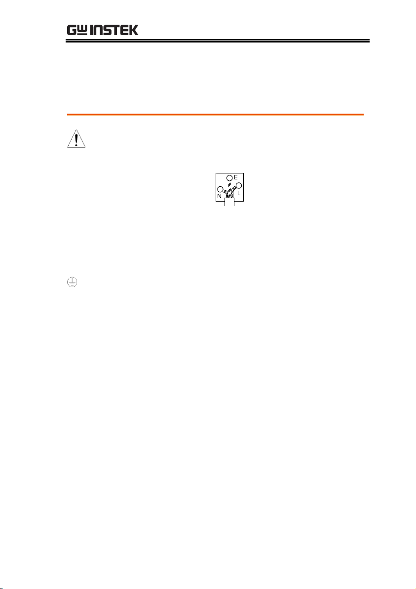
The wire which is coloured Green & Yellow must be connected to
the Earth terminal marked with either the letter E, the earth symbol
or coloured Green/Green & Yellow.
The wire which is coloured Blue must be connected to the terminal
which is marked with the letter N or coloured Blue or Black.
The wire which is coloured Brown must be connected to the
terminal marked with the letter L or P or coloured Brown or Red.
If in doubt, consult the instructions provided with the equipment
or contact the supplier.
This cable/appliance should be protected by a suitably rated and
approved HBC mains fuse: refer to the rating information on the
equipment and/or user instructions for details. As a guide, a cable
of 0.75mm2 should be protected by a 3A or 5A fuse. Larger
conductors would normally require 13A types, depending on the
connection method used.
Any exposed wiring from a cable, plug or connection that is
engaged in a live socket is extremely hazardous. If a cable or plug is
deemed hazardous, turn off the mains power and remove the cable,
any fuses and fuse assemblies. All hazardous wiring must be
immediately destroyed and replaced in accordance to the above
standard.
9
Page 10
LCR-8000 Series User Manual
LCR-8200 Series Overview ...............................................11
Series lineup ...................................................................... 11
Characteristics ................................................................... 12
Accessories........................................................................ 14
Package Contents .............................................................. 15
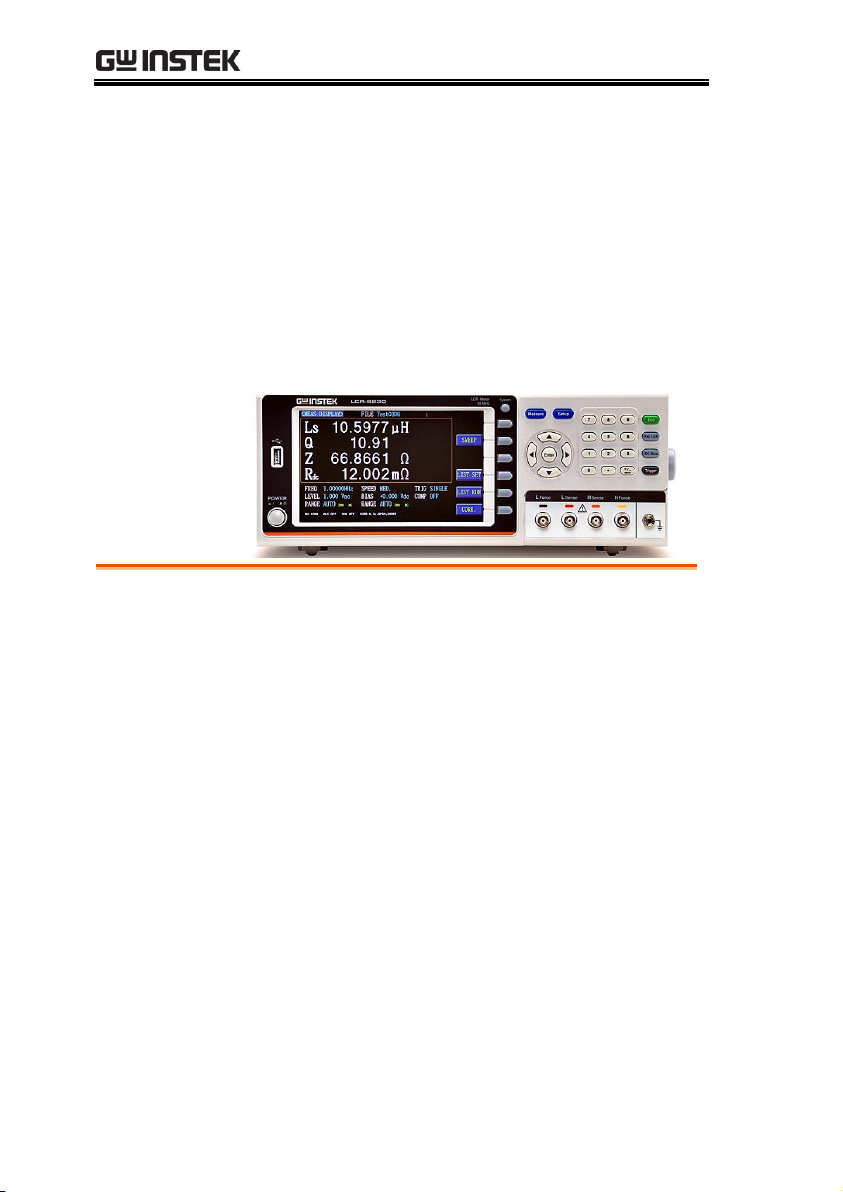
Appearance .....................................................................16
Front Panel ........................................................................ 16
Rear Panel ......................................................................... 18
Set Up .............................................................................19
Tilting the Stand ................................................................ 19
Power UP ........................................................................... 20
Connect to the test terminal ............................................. 21
GETTING STARTED
This chapter describes the LCR-8200 SERIES in a
nutshell, including accessories, package contents,
its main features and front / rear panel
introduction.
10
Page 11

GETTING STARTED
Model name
Basic accuracy
Test speed
Interface
LCR-8230/8220/
8210/8005
±0.08%
400 times/s
RS-232/USB/LAN
GPIB/Handler
Model name
Measurement frequency
LCR-8230
DC, 10~30MHz
LCR-8220
DC, 10~20MHz
LCR-8210
DC, 10~10MHz
LCR-8205
DC, 10~5MHz
LCR-8200 Series Overview
Series lineup
The LCR-8200 series consists of 4 models as list below.
11
Page 12

LCR-8000 Series User Manual
Performance
Signal source frequency range: DC, 10Hz ~
5/10/20/30MHz
Basic accuracy up to ±0.08%
Features
Signal source grade: 10mV ~ 2V / 100μA ~
20mA
ALC function
Output resistance 25Ω/100Ω, switchable
Parameters: |Z|, |Y|, θ, R, X, G, B, L, C, D, Q,
DCR, ESR, Vac, Iac, Vdc, Idc, etc.
Ultra-high measuring speed
Characteristics
Thank you for using LCR-8200 SERIES LCR Meter as your testing
instrument. This Manual contains the detailed installation steps. To
ensure personnel safety and to protect your equipment and data,
please check if the following accessories are fully supplied before
starting the installation.
The test frequency of the LCR-8200 SERIES LCR Meter is DC 10Hz30MHz and the test signal is 10mV-2Vrms and is suitable for the
LCR and DCR testes of AC signals. The measurement in a
continuously changing environment can be executed stage-by-stage
with the test frequency and grade, and high-speed continuous tests
can be performed under different test and mode conditions. The
machine also supports RS-232, USB, LAN and GPIB PC connection
capabilities to improve the design and test efficiency significantly.
The performance, convenience and operation flexibility of the LCR
Meter have become indispensable tools for the professional
measuring technicians.
Such meter can meet customer demands for price, speed, capacity,
accuracy and multi-function by its well-based flexibility in
combination and implementation. Therefore, it can be used in the
testing of a variety of components such as resister, capacitor,
inductor, oscillator, sensor, time-delay wire, filter and resonator.
12
Page 13

GETTING STARTED
Open circuit/short circuit/load calibration
function
Meter mode, multi step list mode, sweep mode
Up to four component parameters can be
selected in the electric meter mode. The
induction and DCR values can be measured and
displayed simultaneously
Up to 48 sets of multistep list programs can be
stored in the permanent memory and up to 15
test steps can be arranged in each program
7" 800*480 TFT LCD color screen
Ultra-low power consumption (<65VA) without
fans and zero noise
Interface
Rapid automation and data access function is
realizable for USB, LAN, GPIB and RS232
interfaces
PC connection data save software is stander
Auto component classification: Comparator
function and Handler BIN classification function
Input: Trigger signal.
13
Page 14

Accessories
Standard
Accessories
Part number
Description
01CR-82H000GT
LCR Meter
82CR-82H00E01
User Manual CD
82GW1SAFE0M01
Safety Instruction Sheet
Region dependent
Power Cord
LCR-06B
Test Fixture(Kelvin Clip)
Optional
Accessories
Part number
Description
LCR-05A
Test Fixture(DIP)
LCR-07
Test Fixture(Clip)
LCR-08A
Test Fixture(SMD)
LCR-10
Test Fixture(SMD)
LCR-15A
Test Fixture(SMD)
DC BIAS BOX
External DC Bias box
GTL-232
RS232C cable
GTL-246
USB cable
LCR-8000 Series User Manual
14
Page 15
GETTING STARTED
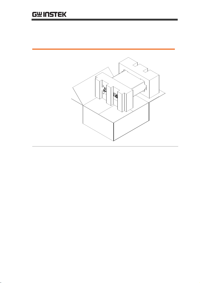
Opening
the box
Contents
(single unit)
Main unit
Test Fixture (Kelvin
Clip)
Power cord x1 (region
dependent)
User manual CD
Safety instruction sheet
Package Contents
Check the contents before using the instrument.
15
Page 16
Appearance
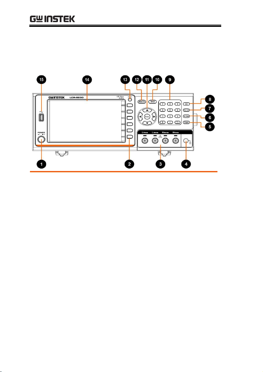
1
Power
This key is used to turn the device
instrument on/off.
2
Function
For executing the function indicated
for the position corresponding to the
Function key.
Soft keys for use to select
corresponding option which located
on the right of the LCD screen.
3
Test
terminals
Test terminals are used to connect test
fixture.
4
Ground
Terminal
This terminal is used for grounding.
5
Trigger
If trigger mode is set to external, this
key can be used to measure trigger.
Front Panel
LCR-8000 Series User Manual
16
Page 17

GETTING STARTED
6
DC BIAS
For control the Bias unit and for
executing on/off.
7
Key Lock
The key will be locked to prevent from
controlling the push key and the
computer by both sides. To use the
keypad again, press this key again.
8
ESC Press this button to return the cursor
to the top left corner of the currently
displayed page or cancel current
setting.
9
Numeric
The numeric keypad is used to input
values for setting.
10
Setup
This key is used for entering
measurement setup page.
11
Arrow Keys
/Enter
The arrow keys are used to navigate
the cursor on the screen.
Enter key is used to confirm the value
which input from the numeric keypad.
When a flash drive is inserted from the
USB port on the front panel. Press
Enter to detecting USB disk and show
USB disk management page.
12
Measure
This key is used for entering
measurement setup page.
13
System
This key is used for entering system
setup page.
14
LCD
7” TFT- LCD display.
15
USB port
The Host port is a type A USB port for
logging data and connecting USB
memory devices only.
USB disk type: Flash drive only
Format: FAT32/exFAT
Max memory size: 128GB.
17
Page 18
Rear Panel
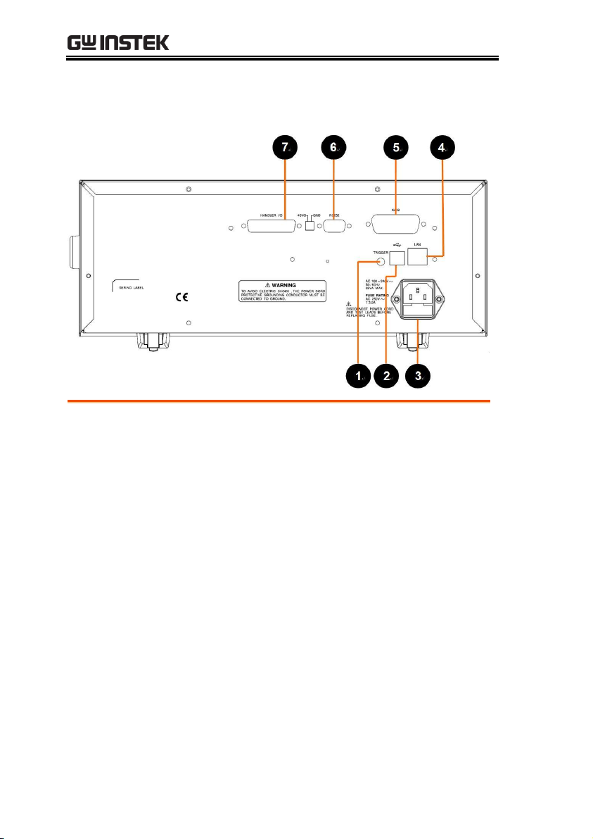
1
TRIGGER
Trigger input port
2
USB
USB port (Type B)
This port is used for remote control.
3
Power Cord
Socket
Power Socket:
AC 100~240V, 50/60Hz, 65VA max
4
LAN
LAN port
5
GPIB
GPIB port
6
RS232
RS-232 port
7
Handler I/O
Handler I/O port
LCR-8000 Series User Manual
18
Page 19
GETTING STARTED
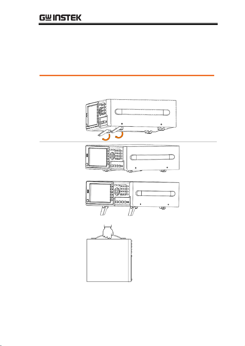
Lifting the instrument, starting from the front stand.
Horizontal
position
Tilt stand
position
Carry position
Set Up
Tilting the Stand
19
Page 20
Power UP
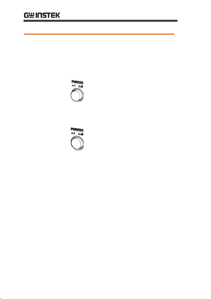
Steps
1. Insert the AC power cord into the power
socket.
2. Press the power button to turn the LCR-8200
series on.
3. The power button will Press down and the
LCR-8200 series will start to boot up.
LCR-8000 Series User Manual
20
Page 21
GETTING STARTED
Background
Please use the test fixture to connect to the test
terminal for testing. Please follow the procedure
below to connect.
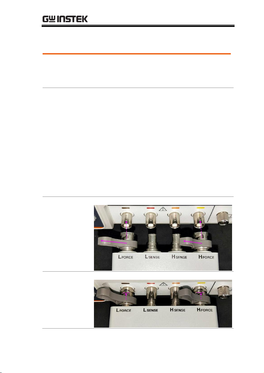
Steps
Please insert the test fixture into the terminal of
the test equipment correctly.
1. Turn the left and right handles of the test
fixture to turn the BNC notch to the top and align
the BNC bumps of the test equipment.
2. Test the fixture into the BNC terminal of the
test equipment.
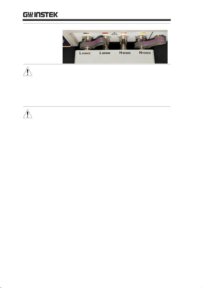
3. Rotate the left and right handles of the test
fixture to the right and push the test fixture to the
end. As shown below.
Connection
diagram
1.
2.
Connect to the test terminal
21
Page 22
LCR-8000 Series User Manual
3.
Note
Avoid wrong connection, which would lead to
incorrect reading value.
In order to ensure the accuracy of the instrument,
please use the LCR-8200 optional accessories test
cable for test.
Warning
Before connecting the test leads, make sure the
test leads are not connected to any component to
avoid personal injury or damage to the
instrument.
22
Page 23

MEASURE (METER MODE)
Measure display area description ..................................... 24
Setting parameter .............................................................. 25
Setting frequency............................................................... 27
Setting speed ..................................................................... 29
Setting trigger mode ......................................................... 30
Setting measurement level/ALC/RO ................................ 32
Setting DC bias.................................................................. 34
Setting measurement AC range ........................................ 36
Setting measurement DC range ....................................... 37
Setting trigger delay timer................................................. 38
Setting AC/DC delay timer ................................................ 39
Setting average count ....................................................... 40
Setting display Vm/Im mode ............................................ 41
Setting beep mode ............................................................ 42
Setting statistics mode ..................................................... 43
Setting comparator .......................................................... 44
Setting bin sorting ........................................................... 50
Setting FILE ..................................................................... 56
Setting USB disk.............................................................. 58
MEASURE (METER
MODE)
In this chapter you will learn about all the
measurement-related settings. All the
measurement setting items can be found on the
[MEAS DISPLAY] [MEASURE MODE SETUP]
page.
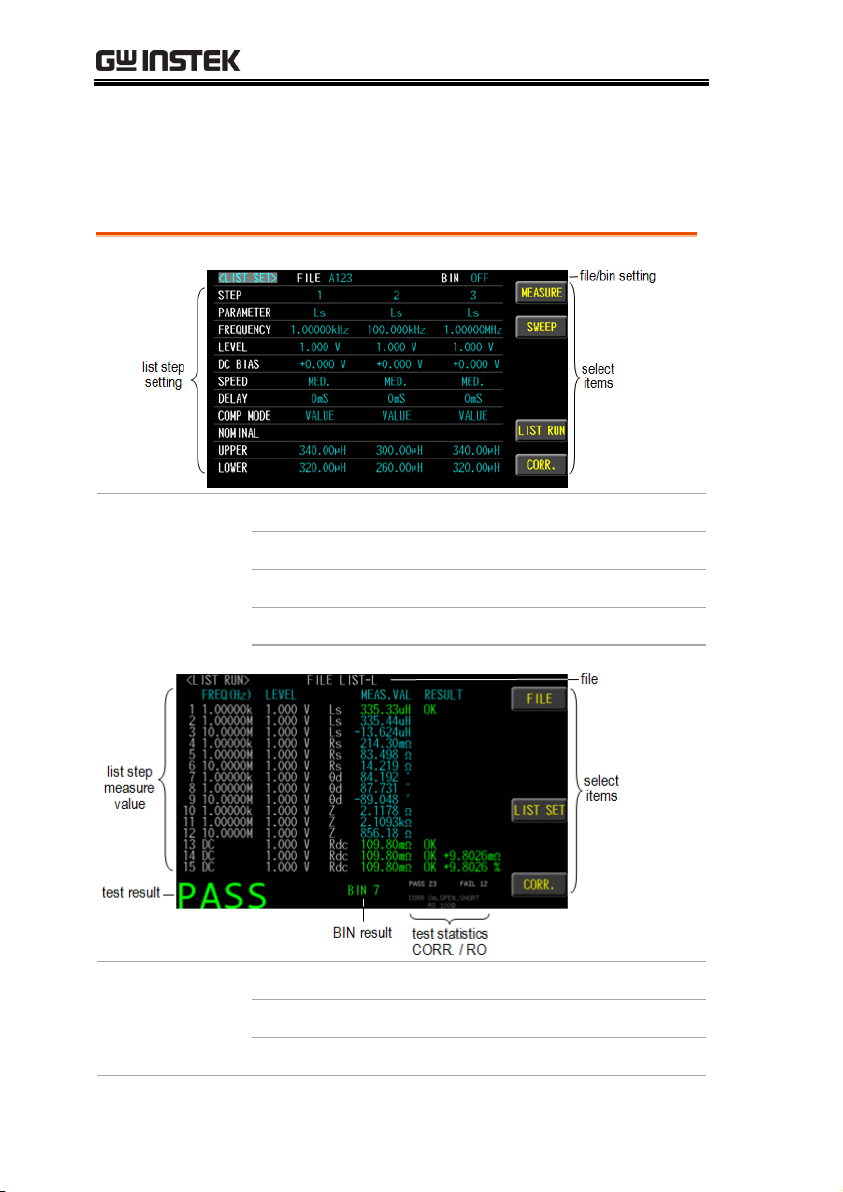
23
Page 24
LCR-8000 Series User Manual
Available
parameter
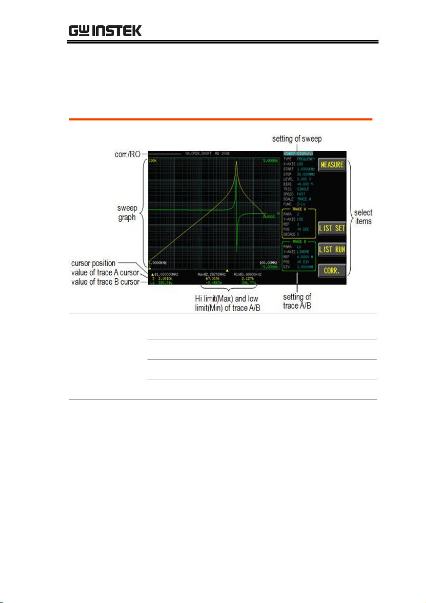
SWEEP
Sweep mode page. Provides the
measurement value to graphic
curve function.
LIST SET
List setting page.
LIST RUN
List run test page.
CORR.
Correction page.
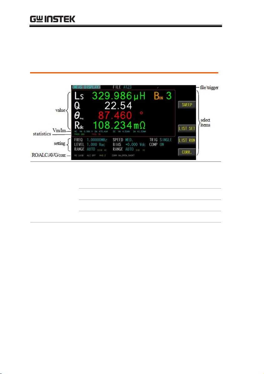
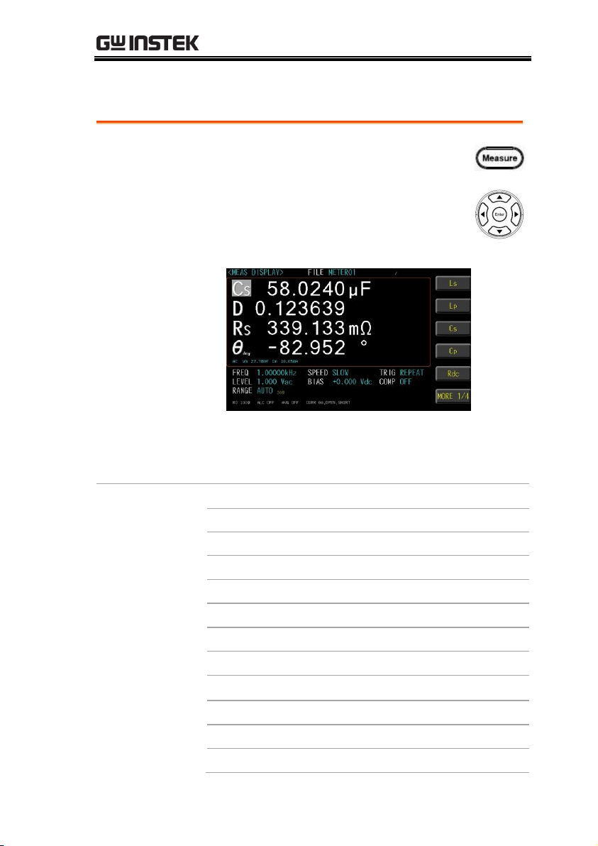
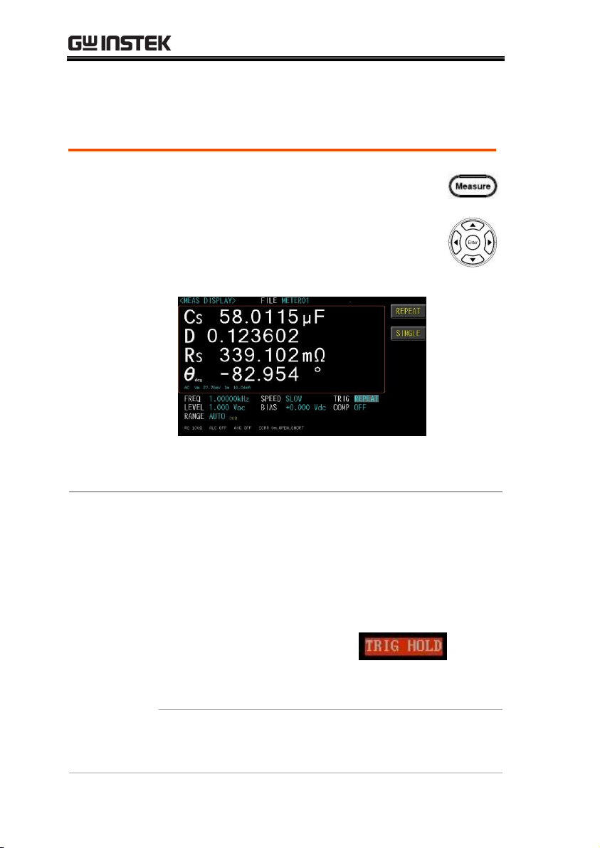
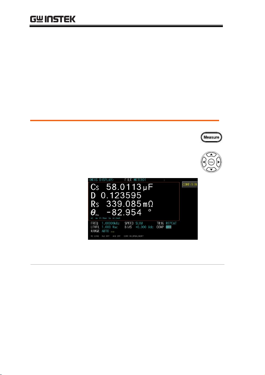
Measure display area description
The measurement display is a Meter mode that provides a single
condition for numerical measurements.
24
Page 25
MEASURE (METER MODE)
Steps
1. Press the Measure button to enter
[MEAS DISPLAY] page.
2. Use arrow keys to move the cursor
and select Parameter 1~4 item on the
[MEAS DISPLAY] page.
3. Use option key on the right of the LCD screen
to select a parameter for this measurement
item.
Parameter
Ls
Equivalent Series Inductance
Lp
Equivalent Parallel Inductance
Cs
Equivalent Series Capacitance
Cp
Equivalent Parallel Capacitance
Rdc
DC Resistance
Rs
Equivalent Series Resistance (ESR)
Rp
Equivalent Parallel Resistance
Z
Absolute value of impedance
θ
deg
Phase angle of impedance(degree)
θ
rad
Phase angle of impedance(radian)
Q
Quality Factor, (Q = 1/D)
D
Dissipation Factor
, Loss coefficient (tanδ)
Setting parameter
25
Page 26
LCR-8000 Series User Manual
R
Resistance
X
Reactance
Y
Absolute value of admittance
G
Conductivity
B
Susceptance
Note
Up to four component parameters can be selected
in the meter mode. The inductance and DCR
values can be measured and displayed
simultaneously.
26
Page 27
MEASURE (METER MODE)
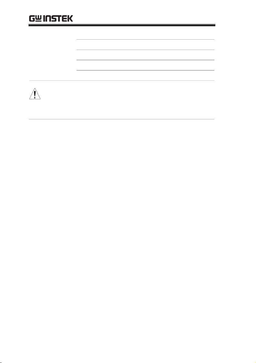
Steps
1. Press the Measure button to enter
[MEAS DISPLAY] page.
2. Use arrow keys to move cursor and
select FREQ item on the [MEAS
DISPLAY] page.
3. Select option key on the right of the LCD
screen to adjust the frequency value by rough
or minor adjusting method or use the numeric
keypad to enter the test frequency.
Available
parameter
Increase the first digit of the frequency
value.
Increase the second digit of the frequency
value
Increase the third digit of the frequency
value
Decrease the third digit of the frequency
value
Setting frequency
The frequency range is 10Hz~5MHz/10MHz/20MHz/30MHz, and
the resolution is set at 6 digits..
27
Page 28

LCR-8000 Series User Manual
Decrease the second digit of the frequency
value
Decrease the first digit of the frequency
value
28
Page 29
MEASURE (METER MODE)
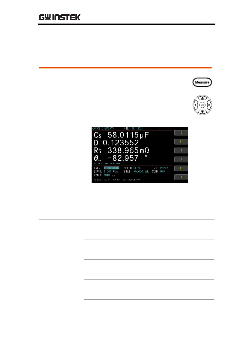
Steps
1. Press the Measure button to enter
[MEAS DISPLAY] page.
2. Use arrow keys to move cursor and
select SPEED item on the [MEAS
DISPLAY] page.
3. Use option key on the right of the LCD screen
to select a test speed for this measurement
item.
Available test
speed
MAX.
2.5ms(>10kHz)
FAST
50ms(>20Hz)
MED.
100ms
SLOW
300ms
SLOW2
600ms
Setting speed
LCR-8200 Series offers 5 test speeds (SLOW2, SLOW, MED., FAST
and MAX.). The slower the test, the more accurate and stable the
test result.
29
Page 30
LCR-8000 Series User Manual
Steps
1. Press the Setup button to enter [MEAS
SETUP] page.
2. Use arrow keys to move cursor and select
TRIGGER item on the [MEAS SETUP]
page.
3. Use option key on the right of the LCD screen to
select a trigger mode for this measurement item.
Available
parameter
REPEAT
Internal trigger mode is also known as
continuous test. The trigger signal
performs continuous test in accordance
with the SPEED setting.
Press the Trigger button to pause the
trigger to stop the measurement and
display the “TRIG HOLD” message on
the top of the LCD.
Again press the Trigger button to resume
continuous triggering.
SINGLE
External trigger mode, including
Manual/Handler/TRIGGER
Input/Remote control mode.
Setting trigger mode
LCR-8200 Series offers REPEAT and SINGLE mode.
30
Page 31

MEASURE (METER MODE)
Manual mode: The device performs a
measurement once the Trigger button is
pressed.
Handler mode: When a negative edge
pulse is received from the handler
interface on the rear panel, the device
performs a measurement cycle.
TRIGGER Input mode: When a
negative edge pulse is received from
the TRIGGER Input on the rear panel,
the device performs a measurement
cycle.
Remote control mode: When a
measurement command is sent from
the RS-232 or USB or GPIB interface,
the device performs a measurement
cycle.
31
Page 32
LCR-8000 Series User Manual
Setting measurement level/ALC/RO
LCR-8200 Series test signal voltage/current level can be set as the
effective value (RMS value) of a sine wave of the test frequency
from the unit’s internal oscillator. The voltage range is 10mV2Vrms and current range is 100uA-20mArms. 2Vrms can only be
used at <= 1MHz.
The ALC (automatic level control) feature adjusts the voltage across
the DUT or the current through the DUT to match the
voltage/current level setting. Using this feature, you can try to
ensure a constant signal level (voltage or current) is applied to the
DUT.
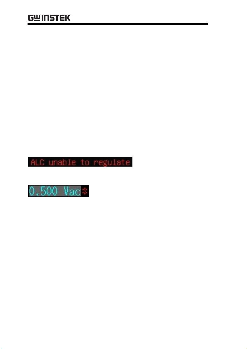
In situations when the actual measuring Vac or Iac goes beyond the
extent that the ALC can regulate, a warning message, “ALC unable
to regulate”, will be shown at the bottom of the screen.
An asterisk will be shown beside the LEVEL V or A unit when the
ALC is turned on.
The RO (output impedance) can be set to 25Ω or 100Ω.
The varied signal source output impedance will lead to the varied
current or the difference of measuring value. If selecting <25Ω>,
then the voltage range is 10mV~1Vrms and the current range is
400uA~40mArms. If it needs to compare test results with Keysight
select 100Ω.
32
Page 33

MEASURE (METER MODE)
Steps
1. Press the Measure button to enter [MEAS
DISPLAY] page.
2. Use arrow keys to move cursor and select
LEVEL item on the [MEAS DISPLAY]
page.
3. Use option key on the right of the LCD screen to
adjust the level value or use the numeric keypad to
enter the test level and select ALC/RO for this
measurement item.
Available
parameter
Increase 0.1Vac/1mAac of the level value
Decrease 0.1Vac/1mAac of the level value
ALC OFF
ALC function turn off
Shown at the bottom of the screen.
ALC ON
ALC function turn on
Shown at the bottom of the screen.
RO 100Ω
Set output impedance 100Ω
Shown at the bottom of the screen.
RO 25Ω
Set output impedance 25Ω
Shown at the bottom of the screen.
33
Page 34

LCR-8000 Series User Manual
Steps
1. Press the Measure button to enter
[MEAS DISPLAY] page.
2. Use arrow keys to move cursor and
select BIAS item on the [MEAS
DISPLAY] page.
3. Select option key on the right of the LCD
screen to adjust the frequency value by rough
or minor adjusting method or use the numeric
keypad to enter the DC Bias voltage.
4. Press the DC Bias button to output the
voltage and the DC Bias button will
illuminate. When the DC Bias is
output, the asterisk is displayed next
to the BIAS V unit.
Setting DC bias
LCR-8200 Series offers DC BIAS ±12V. When input is above the
instrument voltage range will be displayed “Out of range!”.
34
Page 35

MEASURE (METER MODE)
Available
parameter
Increase 1V of the DC Bias value
Increase 0.1V of the DC Bias value
Decrease 0.1V of the DC Bias value
Decrease 1V of the DC Bias value
35
Page 36
LCR-8000 Series User Manual
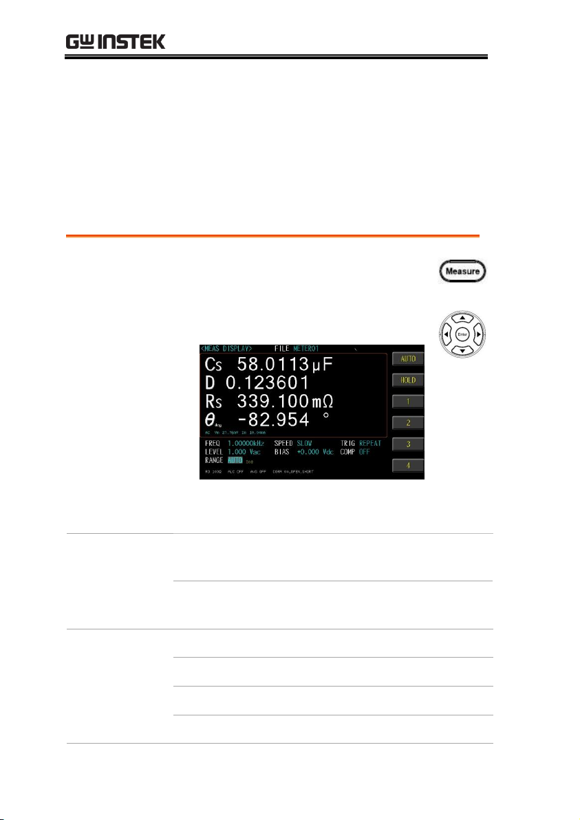
Steps
1. Press the Measure button to enter
[MEAS DISPLAY] page.
2. Use arrow keys to move the cursor to
corresponding measurement AC range.
3. Use option key on the right of the LCD screen to
select a desired measurement range.
Set up range
mode
AUTO
The device will automatically select the
best range to test.
HOLD
The device will always performance test
with a user-specified range.
Measurement
range
1
Set 30Ω range
2
Set 300Ω range
3
Set 3kΩ range
4
Set 30kΩ range
Setting measurement AC range
The range recommendation is set to [Auto] for better measurement
accuracy. The actual measured range will be displayed in the lower
left corner of the screen.
When set to [HOLD], faster measurement speeds can be achieved.
However, when the range is selected incorrectly, it will result in
inaccurate or incorrect values.
36
Page 37

MEASURE (METER MODE)
Steps
1. Press the Measure button to enter
[MEAS DISPLAY] page.
2. Use arrow keys to move the cursor to
corresponding measurement DC range.
3. Use option key on the right of the LCD screen to
select a desired measurement range.
Set up range
mode
AUTO
The device will automatically select the
best range to test.
HOLD
The device will always performance test
with a user-specified range.
Measurement
range
1
Set 30Ω range
2
Set 300Ω range
3
Set 3kΩ range
4
Set 30kΩ range
Setting measurement DC range
The range recommendation is set to [Auto] for better measurement
accuracy. The actual measured range will be displayed in the lower
center of the screen.
When set to [HOLD], faster measurement speeds can be achieved.
However, when the range is selected incorrectly, it will result in
inaccurate or incorrect values.
37
Page 38

LCR-8000 Series User Manual
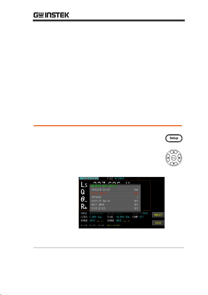
Steps
1. Press the Setup button to enter
[MEASURE MODE SETUP] page.
2. Use arrow keys to move cursor and
select TRIGGER DELAY on the
[MEASURE MODE SETUP] page.
3. Use key pad to input delay timer value ,unit is
ms.
Setting trigger delay timer
LCR-8200 Series can set the delay time before each test by setting
trigger delay timer.
The delay time range is 0ms~5000ms.
38
Page 39
MEASURE (METER MODE)
Steps
1. Press the Setup button to enter
[MEASURE MODE SETUP] page.
2. Use arrow keys to move cursor and
select AC/DC DELAY on the
[MEASURE MODE SETUP] page.
3. Use key pad to input delay timer value ,unit is
ms.
Setting AC/DC delay timer
LCR-8200 Series can set the AC/DC delay time when Rdc
parameter enable .
The inductance and Rdc values can be measured and displayed
simultaneously.
When the inductance is measured by Rdc, a current flows through
the generated magnetic field. When the DC signal ends, the
inductance will generate a back electromotive force. If the AC
signal is subsequently sent out for measurement, the L value may
cause an error. To avoid this problem, you can set the AC/DC
delay timer to reduce the effect of back EMF on the measurement.
This delay timer will be executed both AC to DC and DC to AC.
The delay time range is 0ms~5000ms.
39
Page 40

LCR-8000 Series User Manual
Steps
1. Press the Setup button to enter
[MEASURE MODE SETUP] page.
2. Use arrow keys to move cursor and
select AVERAGE on the [MEASURE
MODE SETUP] page.
3. Use key pad to input average count value.
Note
This average count setting only works for the AC
measurement parameters, and the DCR
measurement does not perform the averaging
function.
Setting average count
This function is to perform multiple measurements and take an
average result from multiple measurements as the final display
value. The stability and reliability of the measurement results can
be improved by utilizing this function. The number of
measurements can be set from 1 to 64.
40
Page 41

MEASURE (METER MODE)
Steps
1. Press the Setup button to enter
[MEASURE MODE SETUP] page.
2. Use arrow keys to move cursor and
select DISPLAY Vm/Im on t he
[MEASURE MODE SETUP] page.
3. Use option key on the right of the LCD screen
to select a desired item.
Available
parameter
OFF
Turn off the Vm/Im display
ON
Turn on the Vm/Im display
Setting display Vm/Im mode
The test signal voltage and test signal current of the AC and the test
signal voltage and test signal current of the DC on the test object.
Turn on the Vm/Im display to help understand the setting status of
ALC and RO.
41
Page 42

LCR-8000 Series User Manual
Steps
1. Press the Setup button to enter
[MEASURE MODE SETUP] page.
2. Use arrow keys to move cursor and
select BEEP WHEN on the
[MEASURE MODE SETUP] page.
3. Use option key on the right of the LCD screen
to select a desired item.
Available
parameter
OFF
Turn off the beep function
PASS
Buzzer sounds when the test pass
FAIL
Buzzer sounds when the test fail
Setting beep mode
When the comparison function setting is turned on, the value
judgment result will be indicated by color, and the buzzer function
can be set to use the sound to know the measurement result.
42
Page 43

MEASURE (METER MODE)
Steps
1. Press the Setup button to enter
[MEASURE MODE SETUP] page.
2. Use arrow keys to move cursor and
select STATISTICS on the
[MEASURE MODE SETUP] page.
3. Use key pad to input average count value.
Available
parameter
OFF
Turn off the statistics display
ON
Turn on the statistics display
CLEAR
Clear statistics quantity
Setting statistics mode
When the comparison function setting is on, the statistics function
can be turned on to calculate the measurement quantity of PASS
and FAIL.
43
Page 44
LCR-8000 Series User Manual
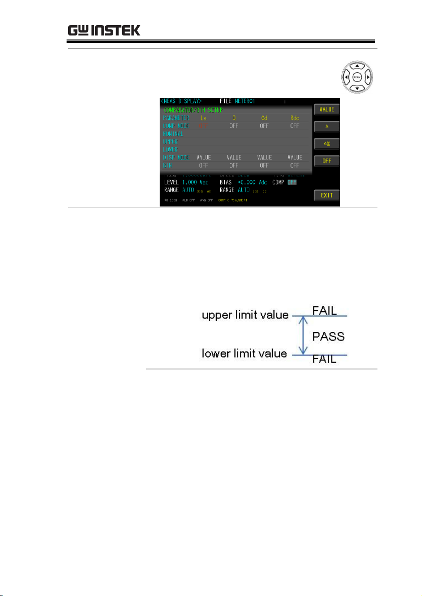
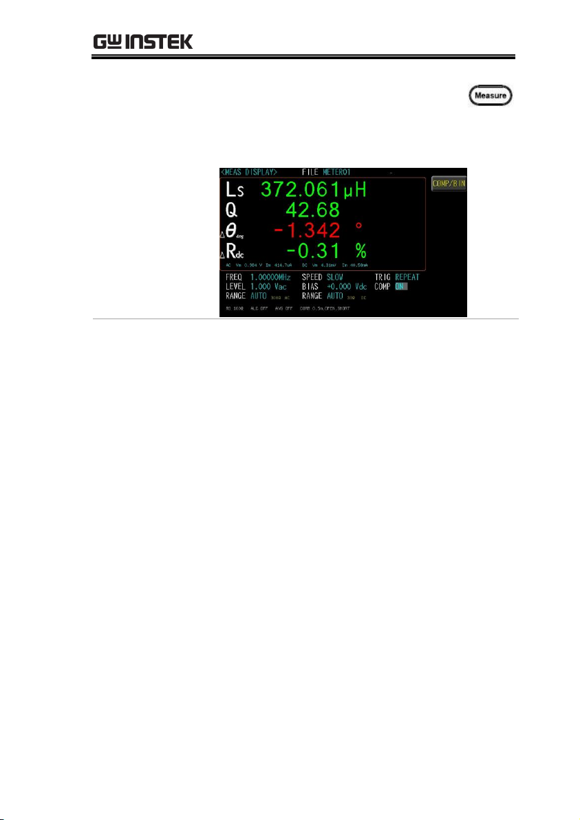
Steps
1. Press the Measure button to enter
[MEAS DISPLAY] page.
2. Use arrow keys to move cursor and
select COMP item.
3. Use option key on the right of the LCD screen to
select COMP/BIN item.
Setting comparator
In this section, user will learn how to set up comparator and bin
sorting. The device can perform comparator function for 1~4
parameter simultaneously or separately. Choose to set the bin
condition for each parameter, which can be divided into 2~9 classes.
Bin methods include equalization, sequence, tolerance and random;
limit value modes include measured values, tolerance values, and
tolerance %.
44
Page 45
MEASURE (METER MODE)
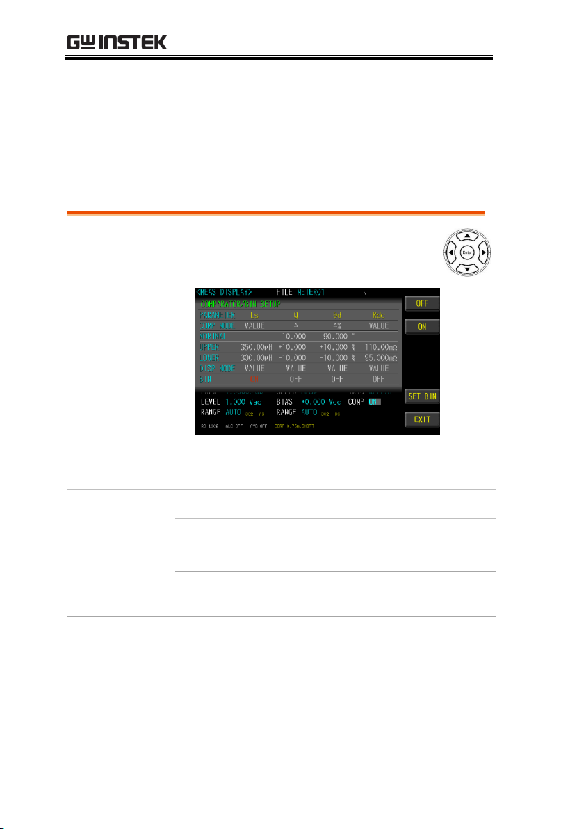
Set up comp
mode
4. Use arrow keys to select COMP
MODE.
Available options
VALUE
The measured values are compared.
Select this mode, the NOMINAL field
does not need to be set, just set the
UPPER and LOWER upper and lower
limits.
45
Page 46
LCR-8000 Series User Manual
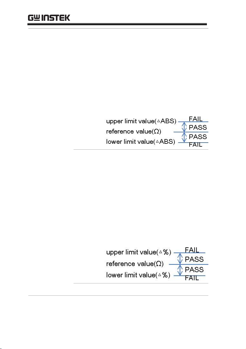
△
The difference between the measured
value and the NOMINAL value is
compared.
Absolute value (Δ) = measure value –
nominal value
Select this mode, the NOMINAL value
and UPPER and LOWER upper and
lower limits must be set.
△%
The difference between the measured
value and the NOMINAL value is
compared with the percentage of the
NOMINAL value.
Deviation percentages (Δ%) = Absolute
value (Δ)/nominal value × 100%
Select this mode, the NOMINAL value
and UPPER and LOWER upper and
lower limits must be set.
OFF
Turn off the comparator function
46
Page 47

MEASURE (METER MODE)
Set up
nominal/upper/lo
wer
1. Use arrow keys to move cursor and
select NOMINAL or UPPER and
LOWER.
2. Use key pad to input value and unit.
Available options
NOMINAL
Compare nominal values. Set only
in the △ and △% modes.
UPPER
Comparison of upper limit
LOWER
Comparison of lower limit
Set up display
mode
3. Use arrow keys to move cursor and
select DISP MODE.
VALUE
Display measurement value
47
Page 48
LCR-8000 Series User Manual
△
Display the difference between the
measured value and the NOMINAL
value
△%
Display the difference between the
measured value and the NOMINAL
value is compared with the percentage
of the NOMINAL value.
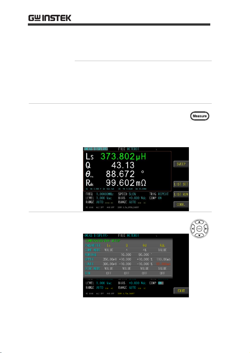
Comparator
result display
4. Press the Measure button to enter
[MEAS DISPLAY] page. Comparator
result is Pass in green color or Fail in
red color.
Set up other
Parameter
5. Use the above steps to set other
fields.
48
Page 49
MEASURE (METER MODE)
Comparator
result display
6. Press the Measure button to enter
[MEAS DISPLAY] page. Comparator
result is Pass in green color or Fail in
red color.
49
Page 50
LCR-8000 Series User Manual
Steps
1. Use arrow keys to move cursor and
select BIN item.
2. Use option key on the right of the LCD screen to
select a desired item.
Available options
OFF
Turn off the bin function.
ON
Turn on the bin function. The SET BIN
option will be displayed.
SET
BIN
Set the parameters of the bin function.
Setting bin sorting
Choose to set the bin condition for each parameter, which can be
divided into 2~9 classes. Bin methods include equalization,
sequence, tolerance and random; limit value modes include
measured values, tolerance values, and tolerance %.
50
Page 51

MEASURE (METER MODE)
Set up parameter
3. Use arrow keys to select PARAMETER
item.
4. Use option key on the right of the LCD screen to
select a desired item. The MEAS DISPLAY has
selected parameters to have display options.
Available options
Off
Turn off the bin function.
PARA1(Ls)
Select the first measurement
parameter (Ls).
PARA2(Q)
Select the second measurement
parameter (Q).
PARA3(Θd)
Select the third measurement
parameter (
Θd).
PARA4(Rdc)
Select the fourth measurement
parameter (Rdc).
51
Page 52
LCR-8000 Series User Manual
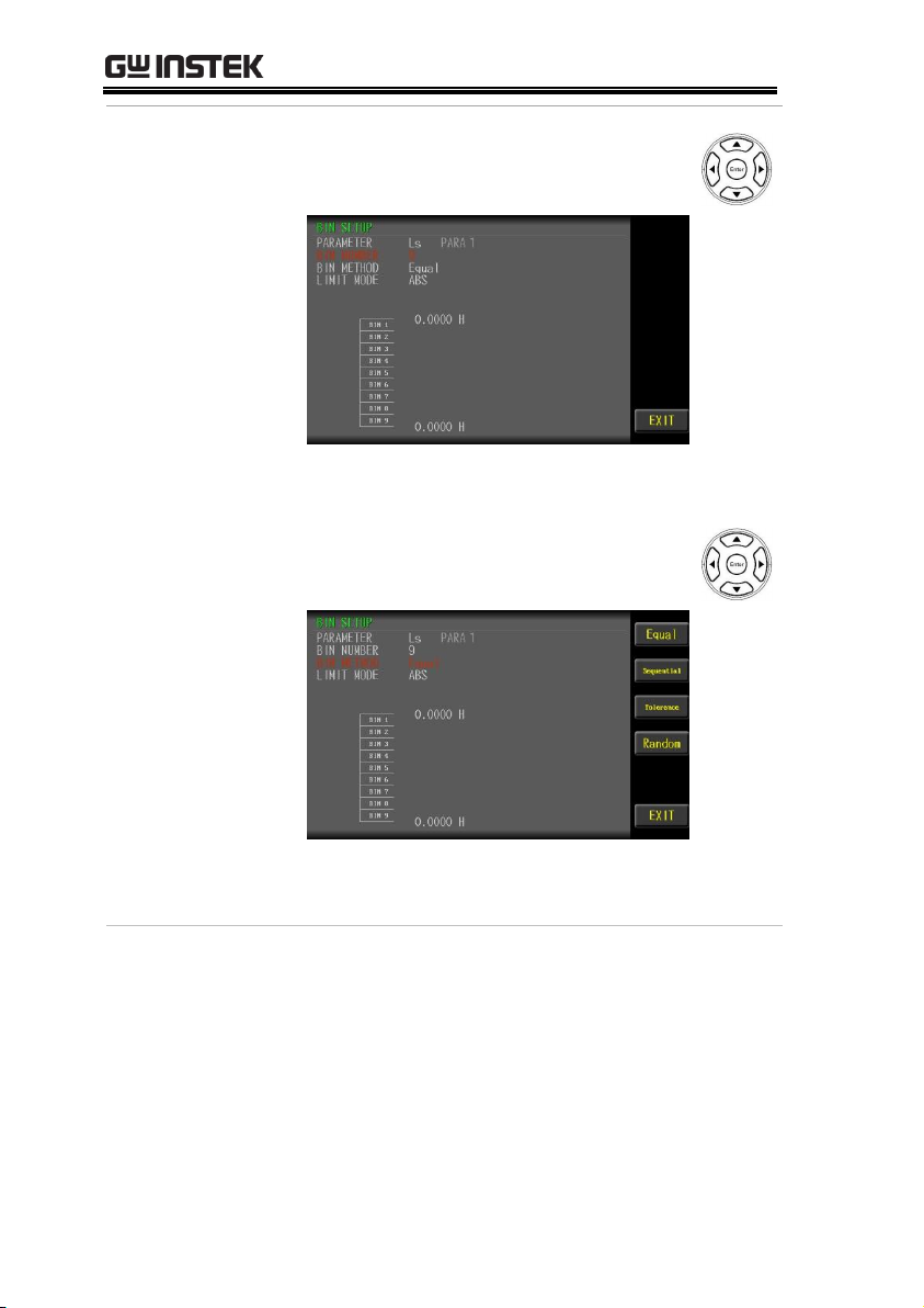
Set up bin
number
7. Use arrow keys to move cursor and
select BIN NUMBER item.
8. Use key pad to input bin number value.(2~9)
Set up bin
method
9. Use arrow keys to move cursor and
select BIN METHOD item.
10. Use option key on the right of the LCD screen to
select a desired item.
52
Page 53

Available options
Equal
Sort by equally average. Set the
high/low value.
Sequential
Sort by order. Set each value.
Tolerance
Sort by order. Set each value.
Random
Sort by user. Set each range value.
MEASURE (METER MODE)
53
Page 54

LCR-8000 Series User Manual
Set up limit mode
11. Use arrow keys to move cursor and
select LIMIT MODE.
12. Use option key on the right of the LCD screen to
select a desired item.
Available options
VALUE
The measured values are compared.
Select this mode, the NOMINAL field
does not need to be set, just set the
UPPER and LOWER upper and lower
limits.
54
Page 55

MEASURE (METER MODE)
△
The difference between the measured
value and the NOMINAL value is
compared.
Absolute value (Δ) = measure value –
nominal value
Select this mode, the NOMINAL value
and UPPER and LOWER upper and
lower limits must be set.
△%
The difference between the measured
value and the NOMINAL value is
compared with the percentage of the
NOMINAL value.
Deviation percentages (Δ%) = Absolute
value (Δ)/nominal value × 100%
Select this mode, the NOMINAL value
and UPPER and LOWER upper and
lower limits must be set.
55
Page 56
LCR-8000 Series User Manual
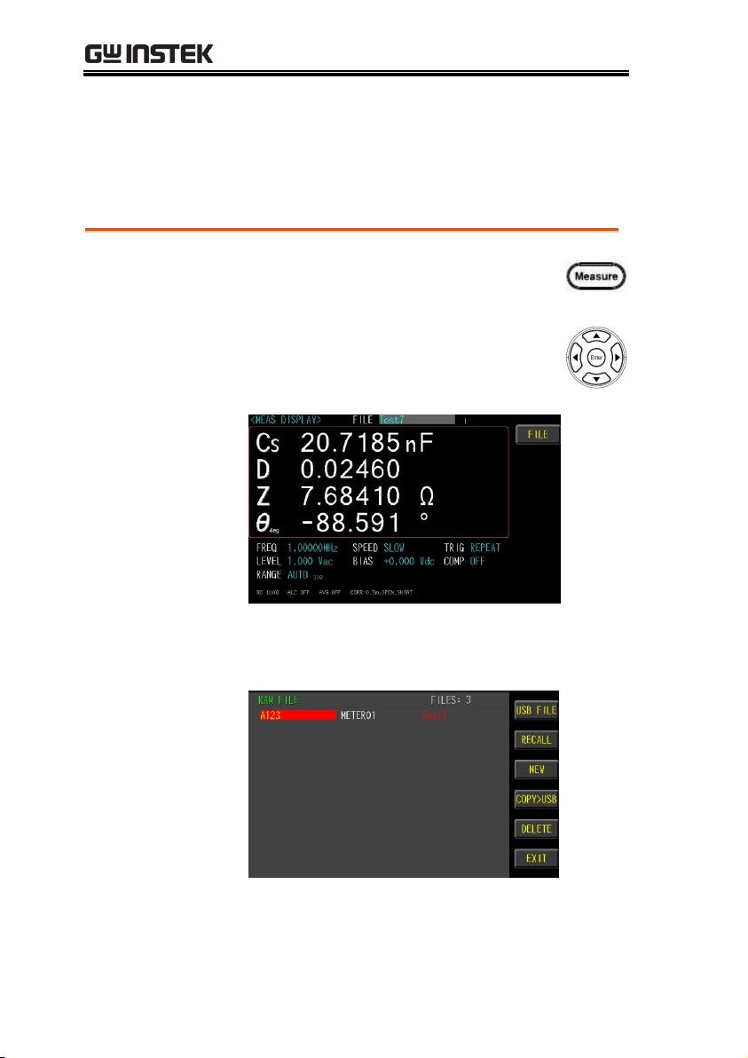
Steps
1. Press the Measure button to enter
[MEASURE DISPLAY] page.
2. Use arrow keys to move cursor and
select FILE on the [MEASURE
DISPLAY] page.
3. Use option key on the right of the LCD
screen to select FILE item.
4. Use option key on the right of the LCD screen
to select a desired item.
Setting FILE
The parameter can be saved in the flash Memory of the instrument.
The meter mode allows the user to access 99 setup groups.
56
Page 57

MEASURE (METER MODE)
Available
parameter
RECALL
load the files in the temporary files
for testing
NEW
Open an empty file and setting the
file name
SAVE AS
Save the test file in the RAM to
another file.
DELETE
Delete the file, the file which is
being used (red) cannot delete.
Note
The LCR-8200 uses the system's temporary files for
testing.
Use "RECALL" to load the files in the instrument
memory into the temporary files of the system.
The file font being used is red and cannot be
deleted. Any parameter change settings will be
saved in the original file instantly.
USB disks can only back up test files. If you want
to use this file, you need to copy the file to the
instrument memory using "COPY> RAM" and
then load it.
57
Page 58

LCR-8000 Series User Manual
Steps
1. Insert a USB disk for using as data recoding.
The instrument will automatically detect the
USB disk format. When it is available, the
USB menu will pop up.
2. Use option key on the right of the LCD
screen to select a desired item. When the USB
disk is plugged in, you can press the ENTER
button to pop up the USB menu.
Setting USB disk
USB disk can store test setup files and LCD screen images and
SWEEP measurement curves and magnitude data.
Available types and file formats:
USB disk type: Flash disk only.
Format: FAT32 / exFAT.
Max memory size: 128GB.
58
Page 59

MEASURE (METER MODE)
Available
options
Save screen
Save LCD screen images to USB disk.
Path>
USB:\LCR8200\SCREEN\SCNxxxx.BMP
File
management
USB file management.
Path> USB:\LCR8200\METER
Format USB
drive
Format the USB disk(FAT32)
59
Page 60

LCR-8000 Series User Manual
Sweep display area description ........................................ 61
Setting type ....................................................................... 62
Setting X-axis ..................................................................... 63
Setting start ....................................................................... 64
Setting stop ....................................................................... 65
Setting level/freq ............................................................... 66
Setting bias ........................................................................ 67
Setting trig ......................................................................... 68
Setting speed..................................................................... 70
Setting scale ...................................................................... 71
Setting func ....................................................................... 72
Setting para ....................................................................... 73
Setting Y-axis ..................................................................... 74
Setting ref .......................................................................... 75
Setting pos ........................................................................ 76
Setting div/decade ............................................................ 77
Setting sweep delay ........................................................... 78
Setting output impedance ................................................ 79
Setting keep previous trace .............................................. 80
Setting trace A/B color ...................................................... 82
Setting USB disk ..............................................................83
SWEEP (GRAPH MODE)
In this chapter you will learn about all the sweeprelated settings. All the sweep items can be found
on the [SWEEP DISPLAY] [SWEEP MODE
SETUP] page.
60
Page 61
SWEEP (GRAPH MODE)
Available
parameter
MEASURE
Measure meter mode page.
LIST SET
List setting page.
LIST RUN
List run test page.
CORR.
Correction page.
Sweep display area description
The sweep display is a sweep graph mode that provides a sweep
range condition for graph measurements.
61
Page 62

LCR-8000 Series User Manual
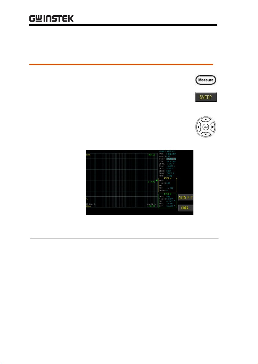
Steps
1. Press the Measure button to enter
[MEAS DISPLAY] page, and then press
the SWEEP function button on the
right side of the LCD to enter the
[SWEEP DISPLAY] page.
2. Use arrow keys to move the cursor and
select TYPE item on the [SWEEP
DISPLAY] page.
3. Use option key on the right of the LCD screen to
select a parameter for this sweep item.
Available
parameter
FREQ.
Change frequency range sweep
condition
Vac
Change Vac range sweep condition
Iac
Change Iac range sweep condition
AUTO
FIT
Automatically adjust the Y-axis scale
and position of the sweep graph
Setting type
Sweep type has 3 kinds, which are frequency, Vac and Iac, respectively.
62
Page 63

SWEEP (GRAPH MODE)
Steps
1. Press the Measure button to enter
[MEAS DISPLAY] page, and then
press the SWEEP function button on
the right side of the LCD to enter the
[SWEEP DISPLAY] page.
2. Use arrow keys to move cursor and
select X-AXIS item on the [SWEEP
DISPLAY] page.
3. Use option key on the right of the LCD screen
to select a parameter for this sweep item.
Available
parameter
LINEAR
The starting value to the ending value,
equal to 251 points
LOG
The starting value to the ending value,
use the logarithm to distinguish 267
points (maximum). Different points
depending on the status of the range
setting
AUTO
FIT
Automatically adjust the Y-axis scale
and position of the sweep graph
Setting X-axis
The X-axis scale shows 2 modes LINEAR and LOG.
63
Page 64
LCR-8000 Series User Manual
Steps
1. Press the Measure button to enter
[MEAS DISPLAY] page, and then press
the SWEEP function button on the
right side of the LCD to enter the
[SWEEP DISPLAY] page.
2. Use arrow keys to move the cursor and
select START item on the [SWEEP
DISPLAY] page.
3. Use the numeric keypad to enter the test
frequency (Vac or Iac) and unit.
Setting start
Sweep test condition start value. (frequency, Vac, Iac)
64
Page 65

SWEEP (GRAPH MODE)
Steps
1. Press the Measure button to enter
[MEAS DISPLAY] page, and then press
the SWEEP function button on the
right side of the LCD to enter the
[SWEEP DISPLAY] page.
2. Use arrow keys to move the cursor and
select STOP item on the [SWEEP
DISPLAY] page.
3. Use the numeric keypad to enter the test
frequency (Vac or Iac) and unit.
Setting stop
Sweep test condition stop value. (frequency, Vac, Iac)
65
Page 66
LCR-8000 Series User Manual
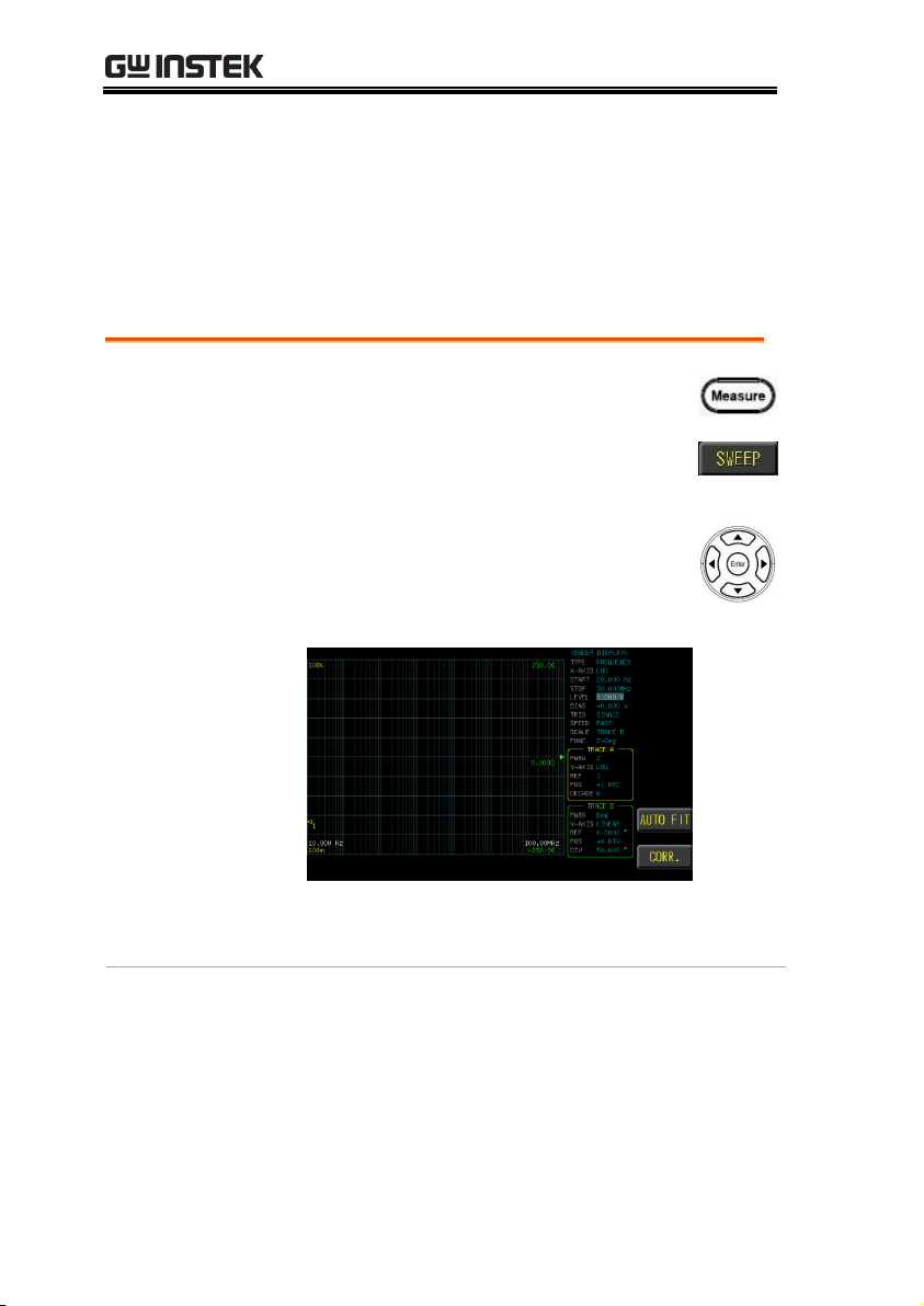
Steps
1. Press the Measure button to enter
[MEAS DISPLAY] page, and then press
the SWEEP function button on the
right side of the LCD to enter the
[SWEEP DISPLAY] page.
2. Use arrow keys to move the cursor and
select LEVEL/FREQ item on the
[SWEEP DISPLAY] page.
3. Use the numeric keypad to enter the test
Vac/Iac (frequency) and unit.
Setting level/freq
When performing a frequency sweep test, you need to set the test
voltage/current (Vac/Iac). If you are performing a voltage/current
scan test, you need to set the test frequency. The voltage range is
10mV-2Vrms and current range is 0.1mA-20mArms. 2Vrms can
only be used at <= 1MHz.
66
Page 67
SWEEP (GRAPH MODE)
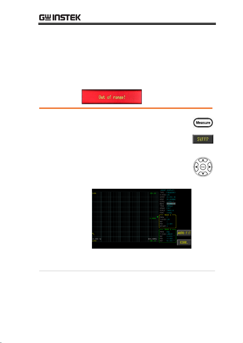
Steps
1. Press the Measure button to enter
[MEAS DISPLAY] page, and then
press the SWEEP function button on
the right side of the LCD to enter the
[SWEEP DISPLAY] page.
2. Use arrow keys to move the cursor
and select BIAS item on the [SWEEP
DISPLAY] page.
3. Use the numeric keypad to enter the test dc
bias and unit.
Setting bias
LCR-8200 Series offers DC BIAS ±12V. BIAS has a set value, when
the trigger test starts, DC BIAS will automatically turn on the output,
and the DC BIAS button indicator will light up; at the end of the test,
DC BIAS will automatically turn off and the light will be off.
When input is above the instrument voltage range will be displayed
“Out of range!”.
67
Page 68
LCR-8000 Series User Manual
Steps
1. Press the Measure button to enter
[MEAS DISPLAY] page, and then
press the SWEEP function button on
the right side of the LCD to enter the
[SWEEP DISPLAY] page.
2. Use arrow keys to move the cursor
and select TRIG item on the [SWEEP
DISPLAY] page.
3. Use option key on the right of the LCD screen
to select a trigger mode for this sweep item.
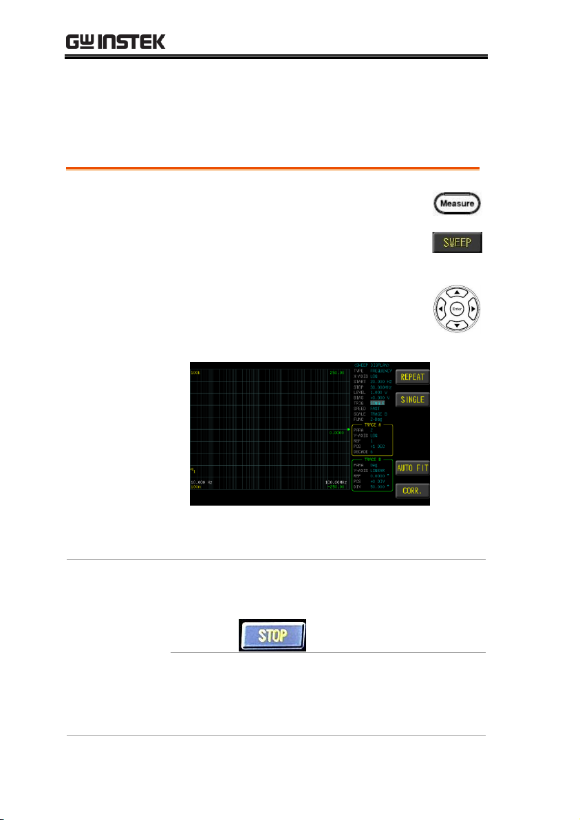
Available
parameter
REPEAT
Continuous sweep test. Press the STOP
function button on the right side of the
LCD to stop the SWEEP test.
SINGLE
External trigger mode, including
Manual/Handler/TRIGGER
Input/Remote control mode.
Manual mode: The device performs a
Setting trig
Trig mode has REPEAT and SINGLE mode. Press the Trigger
button to start the sweep test once.
68
Page 69

SWEEP (GRAPH MODE)
sweep test once the Trigger button is
pressed.
Handler mode: When a negative edge
pulse is received from the handler
interface on the rear panel, the device
performs a sweep test cycle.
TRIGGER Input mode: When a
negative edge pulse is received from
the TRIGGER Input on the rear panel,
the device performs a sweep test
cycle.
Remote control mode: When a
measurement command is sent from
the RS-232 or USB or GPIB interface,
the device performs a sweep test
cycle.
69
Page 70
LCR-8000 Series User Manual
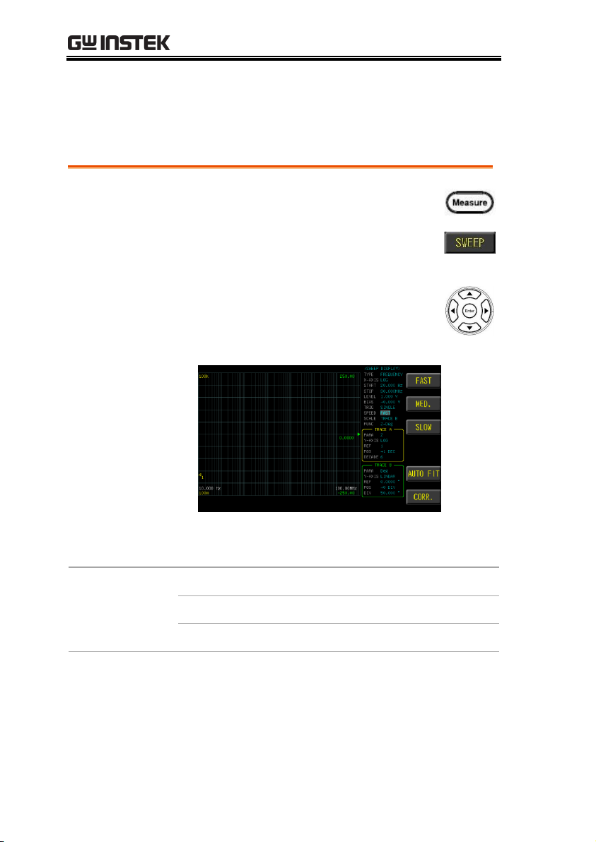
Steps
1. Press the Measure button to enter
[MEAS DISPLAY] page, and then
press the SWEEP function button on
the right side of the LCD to enter the
[SWEEP DISPLAY] page.
2. Use arrow keys to move the cursor
and select SPEED item on the [SWEEP
DISPLAY] page.
3. Use option key on the right of the LCD screen
to select a speed mode for this sweep item.
Available test
speed
FAST
2.5ms (>10kHz)
MED.
50ms (>20Hz)
SLOW
100ms
Setting speed
3 test speeds ( SLOW, MED., FAST). The slower the test, the more
accurate and stable the test result.
70
Page 71

SWEEP (GRAPH MODE)
Steps
1. Press the Measure button to enter
[MEAS DISPLAY] page, and then
press the SWEEP function button on
the right side of the LCD to enter the
[SWEEP DISPLAY] page.
2. Use arrow keys to move the cursor
and select SCALE item on the
[SWEEP DISPLAY] page.
3. Use option key on the right of the LCD screen
to select a scale type for this sweep item.
Available
parameter
TRACE A
Adjust with the trace A setting
TRACE B
Adjust with the trace B setting
AUTO
FIT
Automatically adjust the Y-axis scale
and position of the sweep graph
Setting scale
The scale of the Y-axis is displayed with the setting of trace A or
trace B.
71
Page 72

LCR-8000 Series User Manual
Steps
1. Press the Measure button to enter
[MEAS DISPLAY] page, and then
press the SWEEP function button on
the right side of the LCD to enter the
[SWEEP DISPLAY] page.
2. Use arrow keys to move the cursor
and select FUNC item on the [SWEEP
DISPLAY] page.
3. Use option key on the right of the LCD screen
to select a function type for this sweep item.
Setting func
Select the combination of parameters to be sweep test.
Func1-16: Z-Deg, Y-Deg, R-X, G-B, Z-Cs, Z-Cp, Z-Ls, Z-Lp, Cs-Rs,
Cp-Rp, Cp-G, Cs-D, Ls-Rs, Lp-Rp, Lp-G, Ls-Q.
FUNC selection If you do not have the desired test parameters, you
can go to the PARA item of TRACE A/B and select the required
test parameters.
72
Page 73

Setting para
Steps
1. Press the Measure button to enter
[MEAS DISPLAY] page, and then
press the SWEEP function button on
the right side of the LCD to enter the
[SWEEP DISPLAY] page.
2. Use arrow keys to move the cursor
and select PARA item on the [SWEEP
DISPLAY] page.
3. Use option key on the right of the LCD screen
to select a parameter for this sweep item.
SWEEP (GRAPH MODE)
Select test parameters of trace A or trace B.
73
Page 74

LCR-8000 Series User Manual
Steps
1. Press the Measure button to enter
[MEAS DISPLAY] page, and then
press the SWEEP function button on
the right side of the LCD to enter the
[SWEEP DISPLAY] page.
2. Use arrow keys to move cursor and
select Y-AXIS item on the [SWEEP
DISPLAY] page.
3. Use option key on the right of the LCD screen
to select a parameter for this sweep item.
Available
parameter
LINEAR
The starting value to the ending value,
equal to 400 points
LOG
The starting value to the ending value,
use the logarithm to distinguish 400
points (maximum). Different points
depending on the status of the range
setting
AUTO
FIT
Automatically adjust the Y-axis scale
and position of the sweep graph
Setting Y-axis
The Y-axis scale shows 2 modes LINEAR and LOG of trace A or
trace B.
74
Page 75

SWEEP (GRAPH MODE)
Steps
1. Press the Measure button to enter
[MEAS DISPLAY] page, and then
press the SWEEP function button on
the right side of the LCD to enter the
[SWEEP DISPLAY] page.
2. Use arrow keys to move the cursor
and select REF item on the [SWEEP
DISPLAY] page.
3. Use option key on the right of the LCD screen
to select a scale type for this sweep item.
Available
parameter
MOVE↑
Reference point scale is adjusted
downwards
MOVE↓
Reference point scale is adjusted
upwards
AUTO
FIT
Automatically adjust the Y-axis scale
and position of the sweep graph
Setting ref
Set the Y-axis reference point scale for trace A or B. This parameter
can be set by selecting LINEAR in Y-axis.
75
Page 76
Setting pos
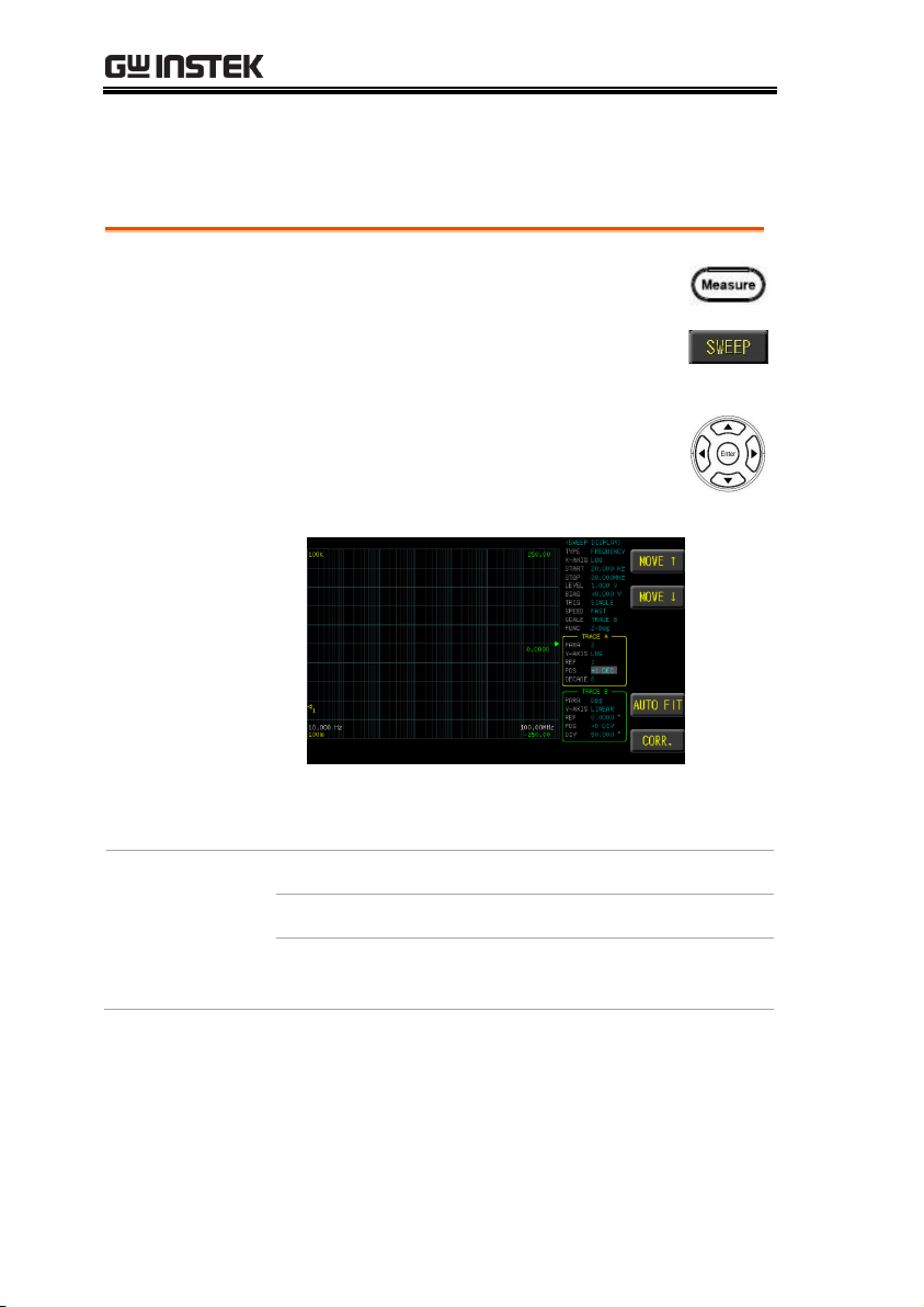
Steps
1. Press the Measure button to enter
[MEAS DISPLAY] page, and then
press the SWEEP function button on
the right side of the LCD to enter the
[SWEEP DISPLAY] page.
2. Use arrow keys to move the cursor
and select POS item on the [SWEEP
DISPLAY] page.
3. Use option key on the right of the LCD screen
to select a scale type for this sweep item.
Available
parameter
MOVE↑
Move the sweep graphic up
MOVE↓
Move the sweep graphic down
AUTO
FIT
Automatically adjust the Y-axis scale
and position of the sweep graph
LCR-8000 Series User Manual
Move the graphic of trace A or trace B.
76
Page 77

SWEEP (GRAPH MODE)
Steps
1. Press the Measure button to enter
[MEAS DISPLAY] page, and then
press the SWEEP function button on
the right side of the LCD to enter the
[SWEEP DISPLAY] page.
2. Use arrow keys to move the cursor
and select DIV (LINEAR) or
DECADE (LOG) item on the [SWEEP
DISPLAY] page.
3. Use option key on the right of the LCD screen
to select a scale type for this sweep item.
Available
parameter
ZOOM-
Scale of each interval becomes larger
ZOOM+
Scale of each interval becomes smaller
AUTO
FIT
Automatically adjust the Y-axis scale
and position of the sweep graph
Setting div/decade
The scale of the Y-axis is displayed with the setting of trace A or
trace B.
77
Page 78

Steps
1. Press the Measure button to enter
[MEAS DISPLAY] page, and then
press the SWEEP function button on
the right side of the LCD to enter the
[SWEEP DISPLAY] page, and press
the Setup button to enter [SWEEP
MODE SETUP] page.
2. Use arrow keys to move the cursor
and select SWEEP DELAY item on the
[SWEEP MODE SETUP] page.
3. Use the numeric keypad to enter the time (ms).
LCR-8000 Series User Manual
Setting sweep delay
Set the sweep test the delay time between each test point and point.
The delay time range is 0ms~5000ms.
78
Page 79

Steps
1. Press the Measure button to enter
[MEAS DISPLAY] page, and then
press the SWEEP function button on
the right side of the LCD to enter the
[SWEEP DISPLAY] page, and press
the Setup button to enter [SWEEP
MODE SETUP] page.
2. Use arrow keys to move the cursor
and select OUTPUT IMPEDANCE
item on the [SWEEP MODE SETUP]
page.
3. Use the numeric keypad to enter the time (ms).
Available
parameter
100Ω
Set output impedance to 100Ω
25Ω
Set output impedance to 25Ω
SWEEP (GRAPH MODE)
Setting output impedance
The output impedance can be set to 25Ω or 100Ω.
The varied signal source output impedance will lead to the varied
current or the difference of measuring value. If selecting <25Ω>,
then the voltage range is 10mV~1Vrms and the current range is
400µA~40mArms.
If need to compare test results with Keysight select 100Ω.
79
Page 80

Steps
1. Press the Measure button to enter
[MEAS DISPLAY] page, and then
press the SWEEP function button on
the right side of the LCD to enter the
[SWEEP DISPLAY] page, and press
the Setup button to enter [SWEEP
MODE SETUP] page.
2. Use arrow keys to move the cursor
and select KEEP PREVIOUS TRACE
item on the [SWEEP MODE SETUP]
page.
3. Use option key on the right of the LCD screen
to select a desired item.
LCR-8000 Series User Manual
Setting keep previous trace
Save sweep graph for part alignment or adjustment.
80
Page 81
SWEEP (GRAPH MODE)
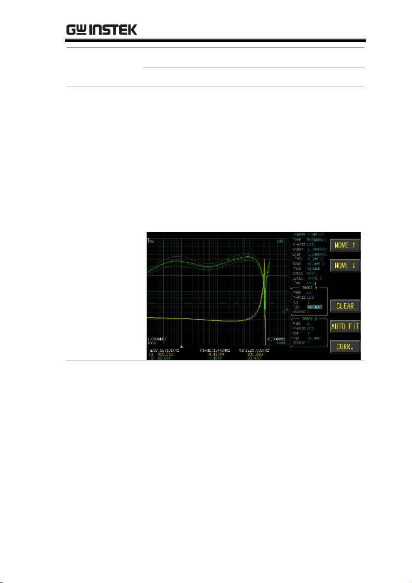
Available
parameter
OFF
Save sweep graph turn off
ON
Save sweep graph turn on
Function
Description
Multiple parts are compared to the measurement
curve, this function can be turned on, and the
parts are measured in order to understand the
difference.
A single part or circuit can be measured before
adjustment. Turn on this function and adjust it
after making adjustments to understand the
difference in adjustment.
Use the CLEAR function key to clear the all
graph.
81
Page 82

Steps
1. Press the Measure button to enter
[MEAS DISPLAY] page, and then
press the SWEEP function button on
the right side of the LCD to enter the
[SWEEP DISPLAY] page, and press
the Setup button to enter [SWEEP
MODE SETUP] page.
2. Use arrow keys to move the cursor
and select TRACE A/B COLOR item
on the [SWEEP MODE SETUP] page.
3. Use option key on the right of the LCD screen
to select a desired color.
Available
parameter
COLOR-
Adjust color down
COLOR+
Adjust color up
LCR-8000 Series User Manual
Setting trace A/B color
Set the display color of trace A or trace B.
82
Page 83

SWEEP (GRAPH MODE)
Steps
1. Insert a USB disk for using as data
recoding. The instrument will
automatically detect the USB disk format.
When it is available, the USB menu will
pop up.
2. Use option key on the right of the LCD
screen to select a desired item. When the
USB disk is plugged in, you can press the
ENTER button to pop up the USB menu.
Setting USB disk
USB disk can store test setup files and LCD screen images and
SWEEP measurement curves and magnitude data.
Available types and file formats:
USB disk type: Flash disk only.
Format: FAT32 / exFAT.
Max memory size: 128GB.
83
Page 84

LCR-8000 Series User Manual
Available
options
Save screen
Save LCD screen images to USB disk.
Path>
USB:\LCR8200\SCREEN\SCNxxxx.B
MP
Save sweep
graphic
Save sweep graph to USB disk.
Path>
USB:\LCR8200\SWEEP\SWPxxxx.BMP
Save sweep
data
Save sweep measure data to USB disk.
Path>
USB:\LCR8200\SWEEP\SWPxxxx.CSV
Format USB
drive
Format the USB disk(FAT32)
84
Page 85

LIST (MULTI STEP MODE)
LIST SET/LIST RUN display area description .................. 86
Setting step ....................................................................... 87
Setting parameter .............................................................. 89
Setting frequency............................................................... 91
Setting level ....................................................................... 92
Setting DC bias.................................................................. 93
Setting speed ..................................................................... 94
Setting delay ...................................................................... 95
Setting comp mode ........................................................... 96
Setting trigger mode ....................................................... 100
Setting trigger delay ........................................................ 103
Setting OUTPUT IMPEDANCE ....................................... 104
Setting ALC ...................................................................... 105
Setting beep when ........................................................... 106
Setting range hold ........................................................... 107
Setting fail reset .............................................................. 108
Setting statistics .............................................................. 109
Setting bin sorting ......................................................... 110
Setting FILE ................................................................... 116
Setting USB disk............................................................ 118
LIST (MULTI STEP MODE)
In this chapter you will learn about all the listrelated settings. All the list setting items can be
found on the[LIST SET] [LIST MODE SETUP]
[LIST RUN] page.
85
Page 86
LCR-8000 Series User Manual
Available
parameter
MEASURE
Meter mode page
SWEEP
Sweep mode page.
LIST RUN
List run test page
CORR.
Correction page
Available
parameter
FILE
List file management
LIST SET
List setting page
CORR.
Correction page
LIST SET/LIST RUN display area description
The list measurement display is a multi-step mode that provides
simultaneous multi-condition measurement for the part.
86
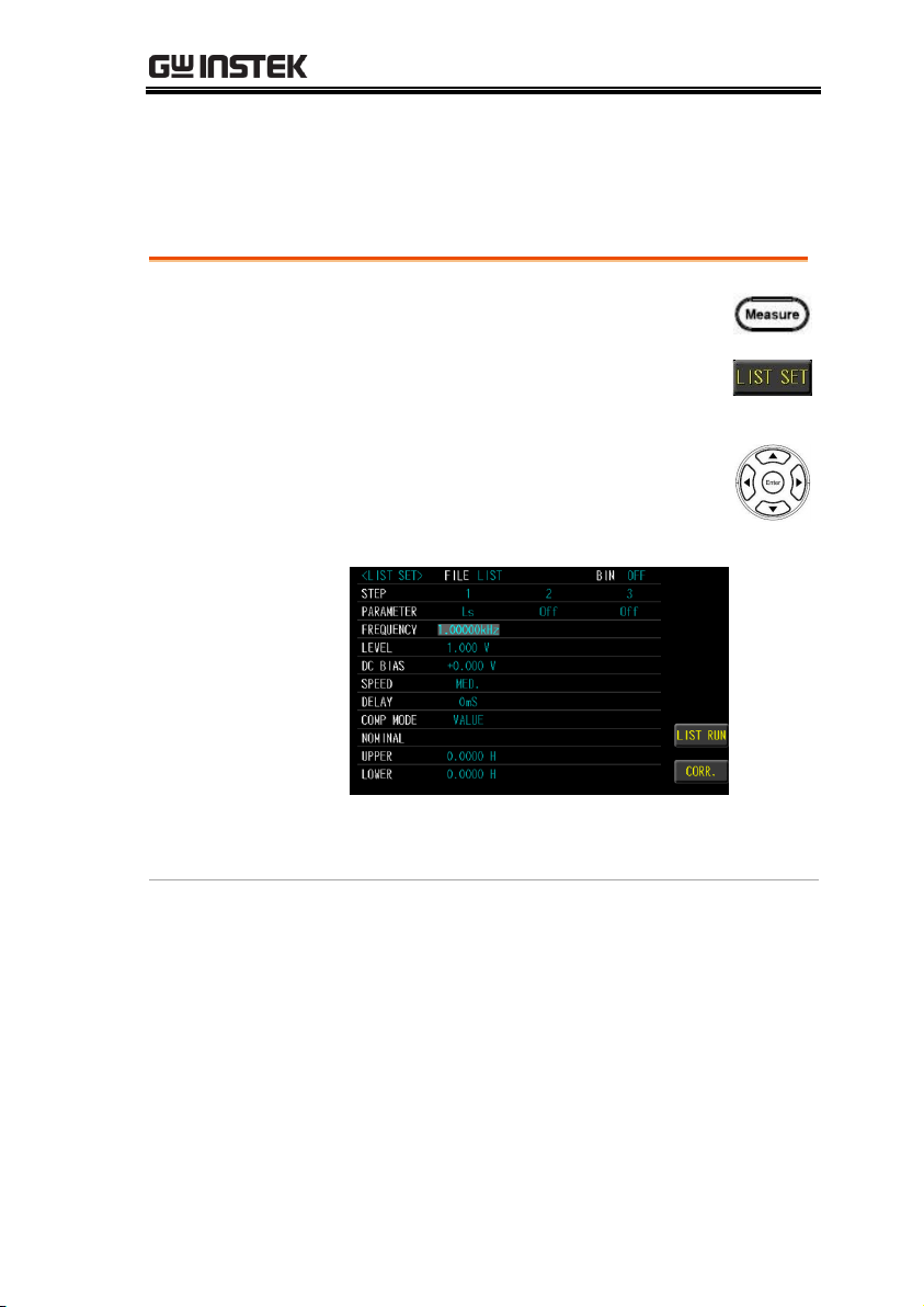
Page 87

Setting step
Steps
1. Press the Measure button to enter
[MEAS DISPLAY] page, and then
press the LIST SET function button
on the right side of the LCD to enter
the [LIST SET] page.
2. Use arrow keys to move cursor and
select STEP item on the [LIST SET]
page.
3. Use option key on the right of the LCD screen
to select a desired item.
LIST (MULTI STEP MODE)
LIST SET has 15 steps to set.
87
Page 88

Available
parameter
COPY
Copy the cursor where the step is
added to the next step.
Copy setp1 to setp2.
INSERT
Insert a blank step in the cursor step to
the next step.
Insert blank step in the next step of
step1.
DELETE
Delete the cursor step.
Delete step3
LCR-8000 Series User Manual
88
Page 89

LIST (MULTI STEP MODE)
Steps
1. Press the Measure button to enter
[MEAS DISPLAY] page, and then
press the LIST SET function button
on the right side of the LCD to enter
the [LIST SET] page.
2. Use arrow keys to move cursor and
select PARAMETER item on the [LIST
SET] page.
3. Use option key on the right of the LCD screen
to select a parameter for this measurement
item.
Parameter
Ls
Equivalent Series Inductance
Lp
Equivalent Parallel Inductance
Cs
Equivalent Series Capacitance
Cp
Equivalent Parallel Capacitance
Rdc
DC Resistance
Rs
Equivalent Series Resistance (ESR)
Rp
Equivalent Parallel Resistance
Z
Absolute value of impedance
θ
deg
Phase angle of impedance(degree)
Setting parameter
89
Page 90

LCR-8000 Series User Manual
θ
rad
Phase angle of impedance(radian)
Q
Quality Factor, (Q = 1/D)
D
Dissipation Factor
, Loss coefficient (tanδ)
R
Resistance
X
Reactance
Y
Absolute value of admittance
G
Conductivity
B
Susceptance
90
Page 91
LIST (MULTI STEP MODE)
Steps
1. Press the Measure button to enter
[MEAS DISPLAY] page, and then
press the LIST SET function button
on the right side of the LCD to enter
the [LIST SET] page.
2. Use arrow keys to move cursor and
select FREQUENCY item on the [LIST
SET] page.
3. Use the numeric keypad to enter the test
frequency.
Setting frequency
The frequency range is 10Hz~5MHz/10MHz/20MHz/30MHz, and
the resolution is set at 6 digits..
91
Page 92
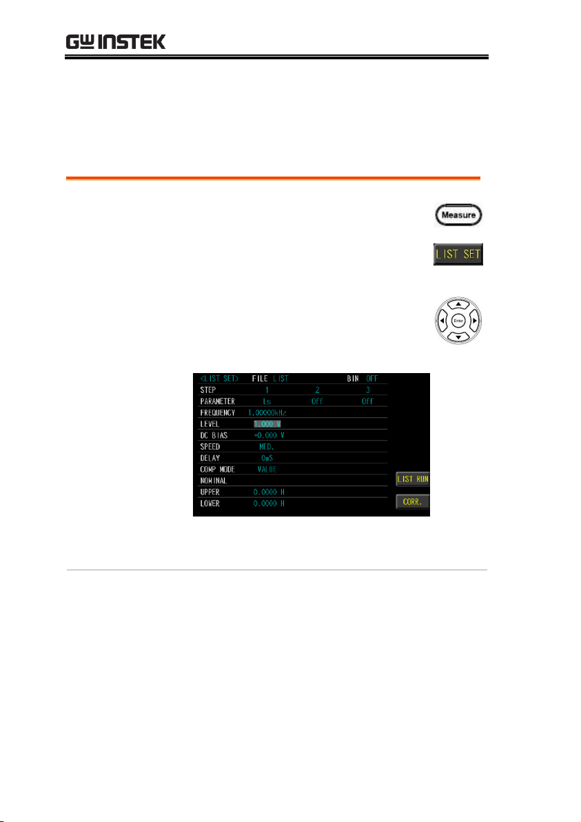
LCR-8000 Series User Manual
Steps
1. Press the Measure button to enter
[MEAS DISPLAY] page, and then
press the LIST SET function button
on the right side of the LCD to enter
the [LIST SET] page.
2. Use arrow keys to move cursor and
select LEVEL item on the [LIST SET]
page.
3. Use the numeric keypad to enter the test
voltage/current.
Setting level
Test signal voltage/current level can be set (RMS value). The
voltage range is 10mV-2Vrms and current range is 0.1mA20mArms. 2Vrms can only be used at <= 1MHz..
92
Page 93

LIST (MULTI STEP MODE)
Steps
1. Press the Measure button to enter
[MEAS DISPLAY] page, and then
press the LIST SET function button
on the right side of the LCD to enter
the [LIST SET] page.
2. Use arrow keys to move cursor and
select DC BIAS item on the [LIST
SET] page.
3. Use the numeric keypad to enter the test DC
Bias.
Setting DC bias
DC BIAS range is -12V~+12V. When input is above the instrument
voltage range will be displayed “Out of range!”. The test step has DC
BIAS. When this step is tested, the instrument will automatically
execute the DC BIAS output, and the DC Bias button will light up and
will automatically turn off at the end of the step.
93
Page 94

LCR-8000 Series User Manual
Steps
1. Press the Measure button to enter
[MEAS DISPLAY] page, and then
press the LIST SET function button
on the right side of the LCD to enter
the [LIST SET] page.
2. Use arrow keys to move cursor and
select SPEED item on the [LIST SET]
page.
3. Use option key on the right of the LCD screen
to select a test speed item.
Available test
speed
MAX.
2.5ms(>10kHz)
FAST
50ms(>20Hz)
MED.
100ms
SLOW
300ms
SLOW2
600ms
Setting speed
5 test speeds (SLOW2, SLOW, MED., FAST and MAX.). The slower
the test, the more accurate and stable the test result.
94
Page 95

LIST (MULTI STEP MODE)
Steps
1. Press the Measure button to enter
[MEAS DISPLAY] page, and then
press the LIST SET function button
on the right side of the LCD to enter
the [LIST SET] page.
2. Use arrow keys to move cursor and
select DELAY item on the [LIST SET]
page.
3. Use the numeric keypad to enter the delay
time.
Setting delay
Set the delay time before each test step. The delay time range is
0ms~5000ms.
95
Page 96
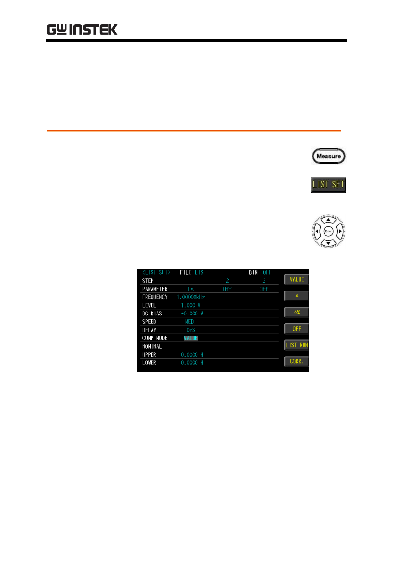
LCR-8000 Series User Manual
Steps
1. Press the Measure button to enter
[MEAS DISPLAY] page, and then press
the LIST SET function button on the
right side of the LCD to enter the [LIST
SET] page.
2. Use arrow keys to move cursor and
select COMP MODE item on the [LIST
SET] page.
3. Use option key on the right of the LCD screen to
select a mode for this setup.
Setting comp mode
The comparison function settings of 1 to 15 steps can be performed
separately. The comparison mode has measured values, tolerance
values and tolerance %.
96
Page 97

Available options
VALUE
The measured values are compared.
Select this mode, the NOMINAL field
does not need to be set, just set the
UPPER and LOWER upper and lower
limits.
△
The difference between the measured
value and the NOMINAL value is
compared.
Absolute value (Δ) = measure value –
nominal value
Select this mode, the NOMINAL value
and UPPER and LOWER upper and
lower limits must be set.
LIST (MULTI STEP MODE)
97
Page 98

LCR-8000 Series User Manual
△%
The difference between the measured
value and the NOMINAL value is
compared with the percentage of the
NOMINAL value.
Deviation percentages (Δ%) = Absolute
value (Δ)/nominal value × 100%
Select this mode, the NOMINAL value
and UPPER and LOWER upper and
lower limits must be set.
OFF
Turn off the comparator function
Set up
nominal/upper/
lower
4. Use arrow keys to move cursor and
select NOMINAL or UPPER and
LOWER.
5. Use key pad to input value and unit.
Available options
NOMINAL
Compare nominal values. Set only
in the △ and △% modes.
98
Page 99

LIST (MULTI STEP MODE)
UPPER
Comparison of upper limit
LOWER
Comparison of lower limit
Comparator
result display
6. Press the LIST RUN function button on
the right side of the LCD to enter [LIST
RUN] page and press the Trigger
button to run test. Comparator result is
Pass in green color or Fail in red color.
99
Page 100
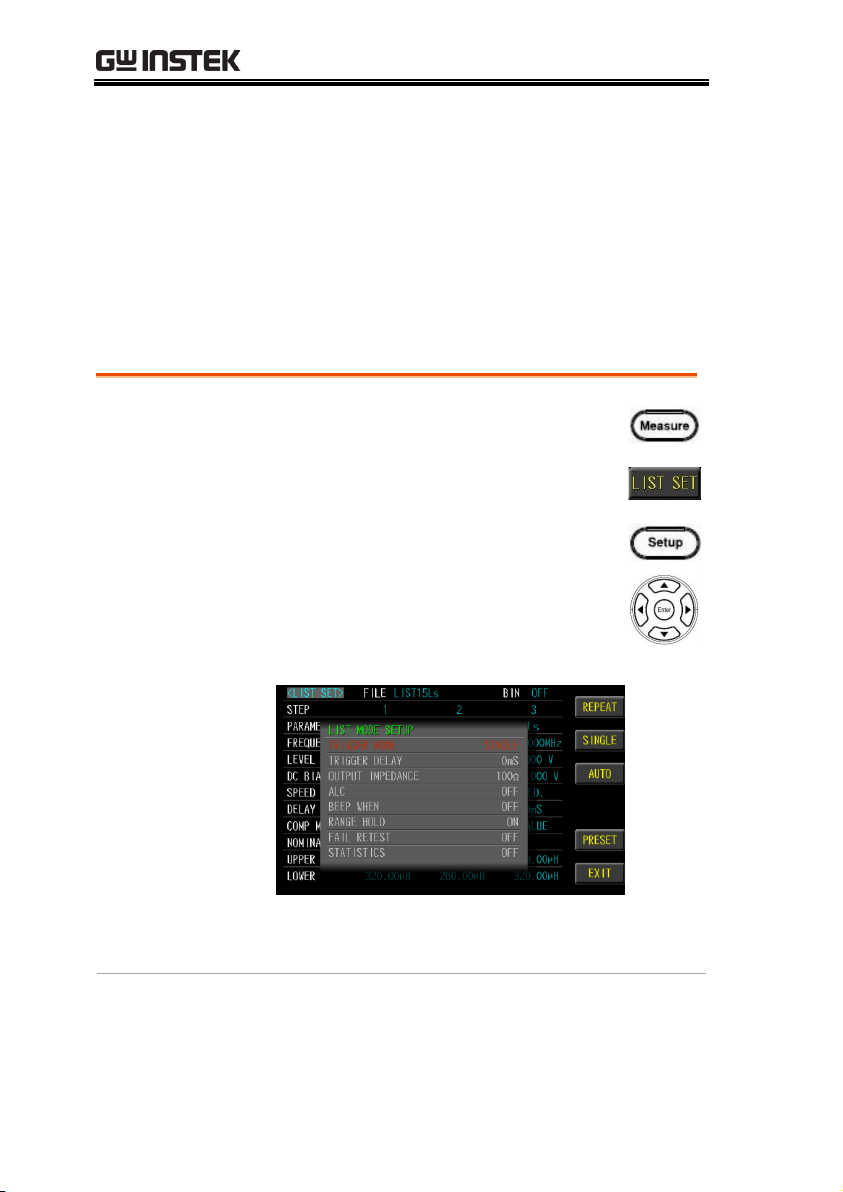
Steps
1. Press the Measure button to enter
[MEAS DISPLAY] page, and press the
LIST SET function button on the right
side of the LCD to enter the [LIST SET]
page, and then press the Setup button
to enter [LIST MODE SETUP] page.
2. Use arrow keys to move cursor and
select TRIGGER MODE item on the
[LIST MODE SETUP] page.
3. Use option key on the right of the LCD screen
to select a desired item.
LCR-8000 Series User Manual
Setting trigger mode
List test step offers REPEAT and SINGLE and AUTO mode.
When the part is tested manually, it is traditionally necessary to
connect the object to be tested, and then press the TRIGGER button
or use the foot switch to start the measurement. Sometimes the
measurement result is wrong because it is not matched, which is
time-consuming and labor-intensive. Switch to AUTO mode and
use automatic trigger to measure, save time and accuracy.
100
 Loading...