

Page 1

LCR-800 Series User Manual
i
CONTENTS PAGE
1. INTRODUCTION……………………………………..……... 1
2. PRECAUTIONS BEFORE OPERATION…….…………….
2-1.Unpacking the instrument………………….…………….
2-2.Checking the Line Voltage…………………..……………
2-3.Environment……………………………………..………..
2-4.Equipment Installation, and Operation…………………
2
2
2
3
3
3. PANEL DESCRIPTION…...……………………..………….. 4
OPERATION…………….………………………………...….
4-1.Connects to DUT….………………..………….……..…...
4-2.Start-Up……….....……………………………..………….
4-3.Zeroing…………………………………………………….
4-4.Menu Functions.…..………………………………………
4-5.Measurement Condition…..……………………………...
8
8
8
8
11
18
4.
5.
SPECIFICATIONS…………………………………………...
35
6. MESSAGE CODE.………………………………………….... 42
7. MAINTENANCE....…………………………………………... 43
8. OPTION 1 (BIN Function for LCR-826/827/829 only)……..
8-1. BIN Functions for Components Sorting……………..….
8-2. BIN Setting Conditions:...………………………………..
8-3. BIN Range Sett i ng : Component Sort ing Range.. ....... .....
44
44
46
52
9. OPTION 2 (RS-232, for LCR-816/817/819 only)…………… 61
Page 2
LCR-800 Series User Manual
ii
SAFETY TERMS AND SYMBOLS
These terms may appear in this manual or on the product:
WARNING : Warning statements ide ntif y condit i on or practice s
that could result in injury or loss of life.
CAUTION: Caution statements identify conditions or practices
that could result in damage to this product or other property.
The followin g sy mb ols may a p pear in this man ua l or on the product:
DANGER ATTENTION Protective Earth (ground)
High Voltage refer to Manual
Conductor Terminal
Terminal
Page 3
LCR-800 Series User Manual
iii
FOR UNITED KINGDOM ONLY
NOTE: This lead / applianc e must only be wired by compete nt per sons
WARNING: THIS APPLIANCE MUST BE EARTHED
IMPORTANT: The wires in this lead are coloured in accordance with the
following c ode:
Green / Yellow: Earth
Blue: Neutral
Brown: Live (Phase)
As the colours of the wires in main leads may not correspond with the
colours marking identified in your plug/appliance, proceed as follows:
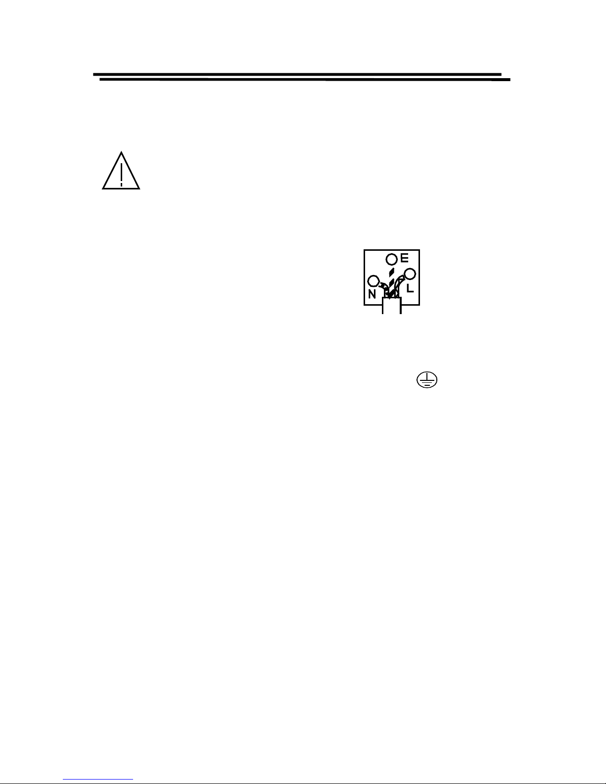
The wire which is coloured Green & Yellow must be connected to the Earth
terminal marked with the letter E or by the earth symbol
or coloured
Green or Green & Yellow.
The wire which is coloured Blue must be connected to the terminal which is
marked with the letter N or coloured Blue or Black.
The wire which is coloured Brown must be connected to the terminal
marked with the letter L or P or coloured Brown or Red.
If in doubt, consult the instr uctions provided wi th the equipment or contac t
the supplier.
This cable/ appliance should be protect ed by a suitably ra ted and approved
HBC mains fuse: refer to the rating information on the equipment and/or
user instructions for details. As a guide, cable of 0.75mm
2
should be
protected by a 3A or 5A fuse. Larger conductors would normally require
13A types, depending on the connection method used.
Any moulded mains connector that requires removal /replacement must be
destroyed by removal of any fuse & fuse carrier and disposed of
immediately, as a plug with bared wires is hazardous if a engaged in live
socket. Any re-wiring must be carried out in accordance with the
information detailed on this label.
Page 4
LCR-800 Series User Manual
iv
EC Declaration of Conformity
We
GOOD WILL INSTRUMENT CO., LTD.
No. 95-11, Pao-Chung Rd., Hsin-Tien City, Taipei Hsien, Taiwan
declares that the below mentioned product
LCR-817/819/827/829/816/826
are herewith confirmed to comply with the requirements set out in the Council
Directive on the Approximation of the Law of Member States relating to
Electromagnetic Compatibility (89/366/EEC, 92/31/EEC, 93/68/EEC) and Low
Voltage Equipment Directive (73/23/EEC).
For the evaluation regarding the Electromagnetic Compatibility and Low Voltage
Equipment Directive, the following standards were applied:
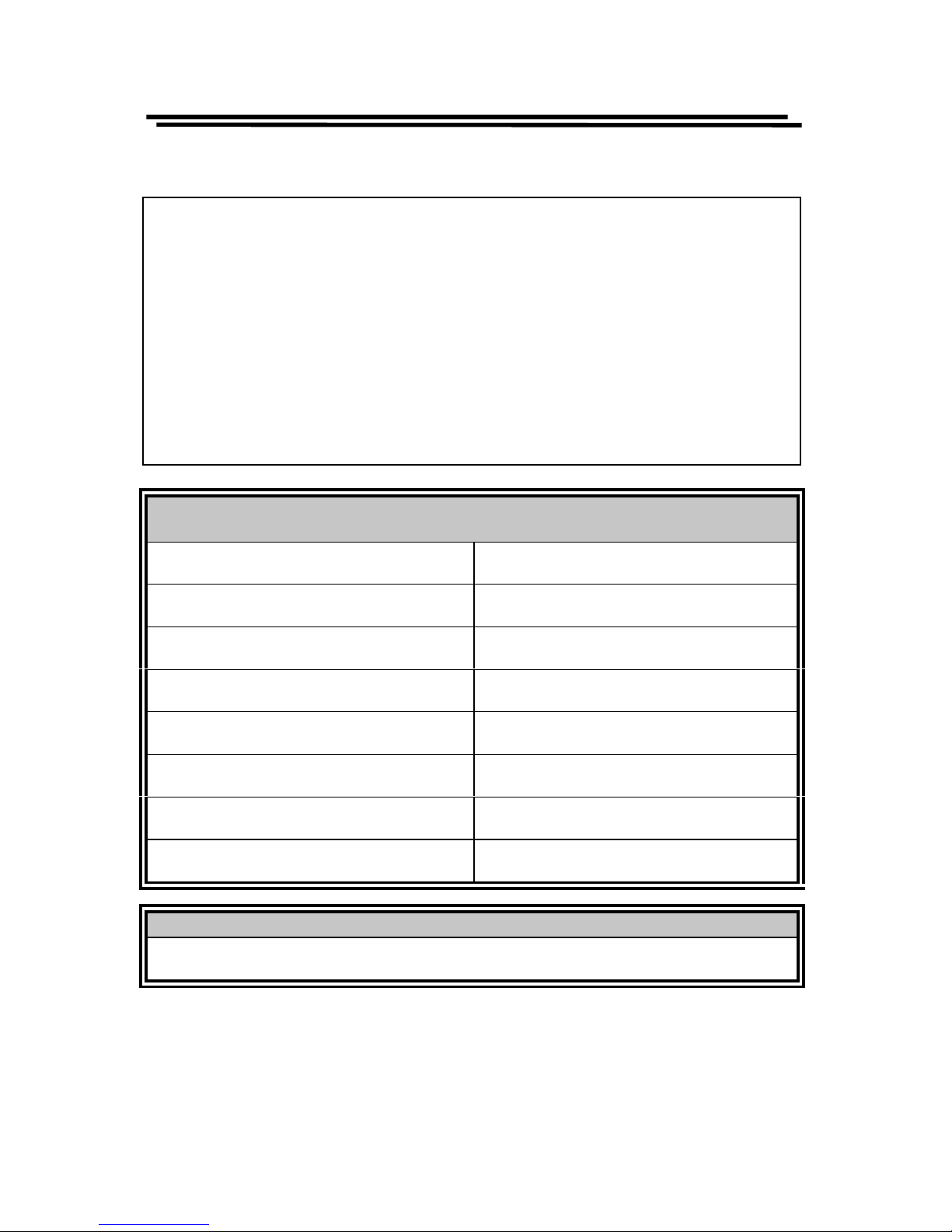
EN 61326-1: Electrical equipment for measurement, control and laboratory use ––
EMC requireme nt s (19 97+A1: 1998)
Conducted and Radiated Emissions
EN 5 5011 Gr oup I cla ss A: 1998
Electrostatic Discharge
EN 61000-4-2: 1995
Current Harmonic
EN 61000-3-2: 1995
Radiated Immunity
EN 61000-4-3: 1996
Voltage Fluctuation
EN 61000-3-3: 1995
Electrical Fast Transients
EN 61000-4-4: 1995
————————————————
Surge Immunity
EN 61000-4-5: 1995
————————————————
Conducted Susceptibility
EN 61000-4-6: 1996
————————————————
Power Frequency Magnetic field
EN 61000-4-8: 1993
————————————————
Voltage Dips/ Interrupts
EN 61000-4-11: 1994
————————————————
Oscillatory Waves
EN 61000-4-12: 1995
Low Voltage Equipment Directive 73/23/EEC & amended by 93/68/EEC
Safety Requirements
EN 61010-1: 1993+A2: 1995; IEC 61010-1: 1990+A1: 1992+A2: 1995
Page 5

LCR-800 Series User Manual
1
1. INTRODUCTION
The pr eci se LCR m eter ser ies ar e au t omat ic, u ser pr ogra mma ble in str umen ts
th at pr ovide h igh r elia bilit y and gr eat preci sion for mea sur ing a wi de var iet y of
impedance parameters. The frequency range of LCR-819/829 covers from 12Hz
to 100kHz, LCR-817/827 from 12Hz to 10kHz, and LCR-816/826 from 100Hz
to 2kHz. The basic accuracy is 0.1% for LCR827/829, 0.05% for LCR-817/819,
and 0.2% for LCR-816/826. The measured results can be displayed on the high
quality LCD monitor with decimal points and units. The measured result
resolution is five full digits for Inductance (
L), Capa citan ce (C), an d Resista nce
(
R) (four full d igit s for D issi pation (D), Quality factor (Q) or C with R). In the
meantime, the LCD monitor is also shown the control status and parameters of
settings. The keypads are easy for menu programming. The LCR Meters’ test
fixture (option) is a method of convenient, reliable, guarded 4-terminal/2 wires
connection of radial and axial leaded components to the LCR Meters. Test
conditions can be stored and recalled from internal memory that will reduce the
setup time for measurement preparing.
Page 6
LCR-800 Series User Manual
2
2. PRECAUTIONS BEFORE OPERATION
2-1. Unpacking the instrument
The product has been fully inspected and tested before shipping from the
factory. Upon receiving the instrument, please unpack and inspect it to
check if there ar e any damag es ca used durin g tr an spor tat i on. If an y dama g e
is found, not ify th e bearer an d /or the dealer im mediately.
2-2. Checking the Line Voltage
The LCR Meters can be operated with AC power source between 100V
rated voltage and 240V rated voltage at a frequency of 50 to 60Hz, no AC
voltage selector is necessary. Power connection to rear panel is through an
AC inl et modul e com p rised of an AC conn ect or and fuse hold er. To change
the fus e p roceed a s fol lows:
! Remove the fuse holder by inserting a small flat head screwdriver
behind the small tab to force the holder outward.
! Install the correct fuse (slow-blow, 3A, 250Vac).
! Re-install the fuse holder back into the LCR Meters AC inlet module,
push in and lock.
WARNING. To avoid electrical shock the power cord protective
grounding conductor must be connected to ground.
WARNING. To avoid personal injury, disconnect the power cord
before removing the fuse holder.
Page 7

LCR-800 Series User Manual
3
2-3. Environment
The norm al ambien t temperat ure range of th e LCR Meters is fr om 10° to
50°C. To operate th e instrument over this specific temp erat ure r ange may
cause damage to the circuits.
Do not use th e LCR M eters in a place wh ere str ong ma gnetic or el ectric
field exists as it may disturb the measurement.
2-4. Equipment Installation, and Operation
Ensure there is proper ventilation for the vents in the LCR meters case. If
this equipment is used not according to the specification, the protection
provided by the equipment may be impaired.
WARNING : This is a Class A product. In a domestic environment
this prduct may cause radio interference in which case the user
may be required to take adequate measures.
Page 8

LCR-800 Series User Manual
4
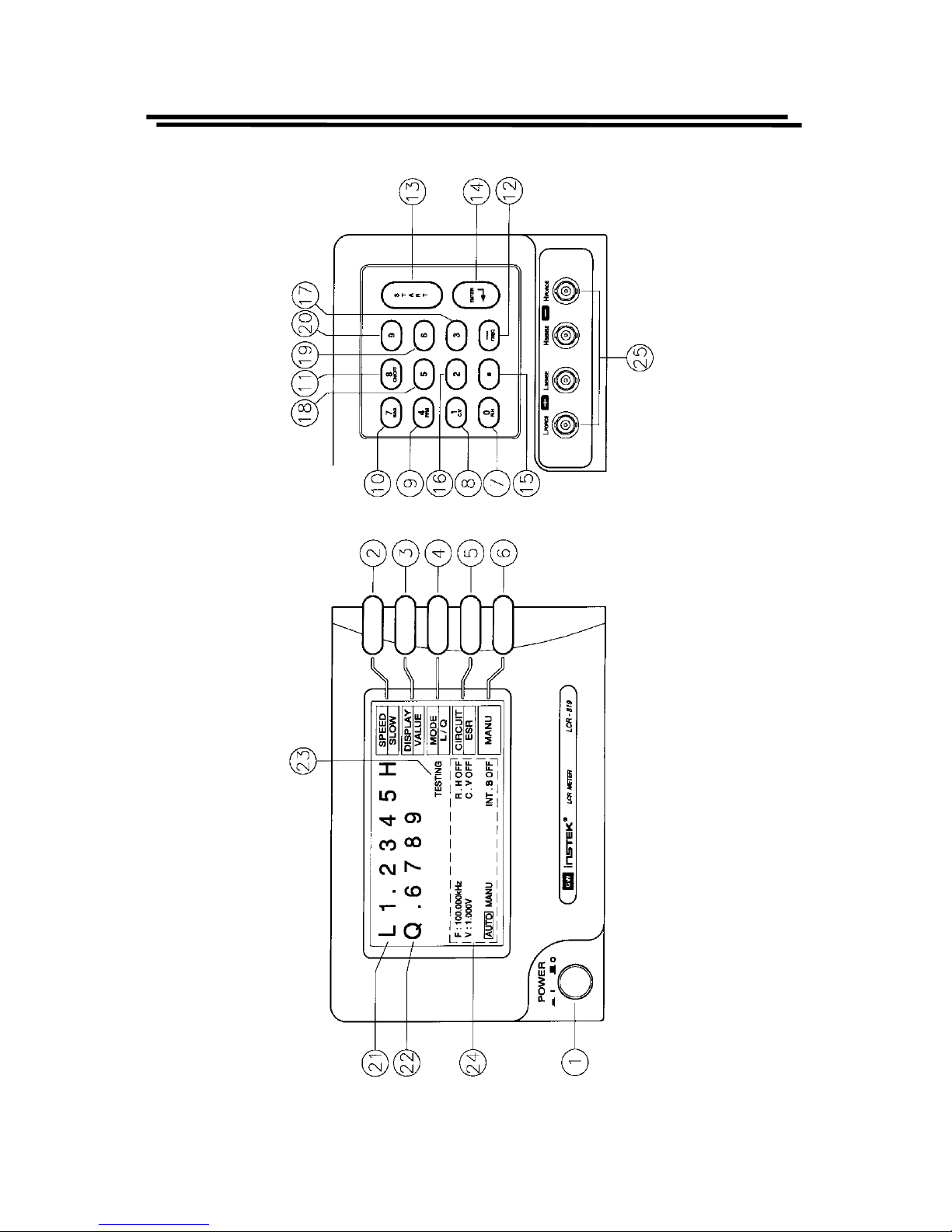
3. PANEL DESCRIP TI ON
(1). Power S witc h
Turns AC Power on or off.
(2). Function keyF1
Soft key functions as indicated on the adjacent LCD monitor.
(3). Function keyF2
Soft key functions as indicated on the adjacent LCD monitor.
(4). Function keyF3
Soft key functions as indicated on the adjacent LCD monitor.
(5). Function keyF4
Soft key functions as indicated on the adjacent LCD monitor.
(6). MENU key
Enters menu display mode or exits sub menu back to main menu.
(7). Compound key
! For making numerical entries as labeled.
! Turns the “RANGE HOLD” mode on or off.
(8). Compound key
! For making numerical entries as labeled.
! Turns the “CONSTANT VOLTAGE” mode on or off.
(9). Compound key
! For making numerical entries as labeled.
! Measures the unit of Dissipation and Quality Factor in PPM.
(Note: The models of LCR-816 and 826 do not have this function.)
Page 9

LCR-800 Series User Manual
5
(10). Compound key
! For making numerical entries as labeled.
! Selects th e “INTERNAL BIAS” mode or “EXTE RNAL BIAS” mode. ( If
this key function is switched to “INTERNAL BIAS” mode, the bottom of
LCD monitor will display the “INT.B” message. If the external DC bias
is selected, the bottom of LCD monitor will display the “EXT.B”
message.)
(11). Compound key
! For making numerical entries as labeled.
! Turns the INTERNAL BIAS mode or EXTERNAL BIAS mode “ON” or
“OFF”.
(12). Compound key
! For making numerical entries as ““ (the negative sign).
! Input s th e “TEST FREQUE N C Y”.
(13). START (Compound k ey)
! Starts measurement sequence. Normally used in the “MANU”
(Triggered) mode.
! Selects “AUTO” or “MANU” mode by pressing this key for 3 seconds at
least.
! The LCR Meters will process the measurement automatically, if the
“AUTO” mode is selected .
(14). ↵
↵↵
↵ key (ENTER)
Thi s key ena bles pr ogrammin g of all speci al fun ction s, t est fr equ enc y, t est
volt a ge, averaging, delay, and nom in al val u e etc.
(15). Symbol key
In puts the d ecimal p oint
(16). Numeral key—“2”
(17). Numeral key—“3”
(18). Numeral key—“5”
(19). Numeral key—“6”
(20). Numeral key—“9”
(21). Primary Displa y
This line can display the measured Inductance, Capacitance, or Resistance.
(22). Secondary Display
Page 10

LCR-800 Series User Manual
6
This line can display the measured Quality Factor or Dissipation or ESR or
EPR.
(23). Instrument status or indicates measurement results based on entered test
limits.
(24). Test conditions
(25). Input terminals
BNC connect ors, connects to device u nder tes t (DUT) .
Conn ectors of t he LCR Met ers
BIAS
Lforce (current, low)
Lsens e ( p otential low)
Hsen se (potential high )
Hforce (current, high)
Page 11
LCR-800 Series User Manual
7
FRONT PANEL
Page 12

LCR-800 Series User Manual
8
4. OPERATION
4-1. Connects to DUT
The LCR Meter s utilize th e stru cture of four wires measur ement which all ows
accurate, easy, and stable measurements and avoids mutual inductance and
interference from measurement signals, noise and other factors inherent with
other types of connections. For the accuracy of measurement, GOODWILL
produces the cable set and test fixture (option) for connection directly to the
fron t pan el BNC connect ors.
4-2. Start-Up
Conn ects th e power cor d of th e LCR M eter s to th e main s socket- outlet . Presses
the
POWER button of front panel to apply the AC power to the LCR Meters.
4-3. Zeroing
In ord er to elimina te stra yed capa citan ce and impedan ce of test ca ble du rin g the
meas urement , the LCR Meter s shoul d be zeroed to corr ect for t est cabl e and/ or
test fixture errors before taking measurements. The corrections are calculated
and stored in memor y of the LCR Met ers dur ing the z eroin g pr ocess. Open and
short circu it zeroing should be d one for test cable and/or te s t fixture. For the be s t
accur a cy, th e test ca ble an d/ or test fix tur e sh oul d be zer oed on ce p er day a t l east
and each time tes t cabl e or test fi xture is changed in general.
The z eroing pr ocess of open an d sh ort cir cu its are following:
Open Circuit
! The t es t cable or tes t fixture should be open with n o com p onent connect ed .
! Press MENU key.
! Press F1 key to select “OFFSET” menu.
! Press F1 key to sele ct open cir cu it zeroin g (the “CAP OFFSE T” i s indicated
on the adjacent LCD mon itor.).
Page 13

LCR-800 Series User Manual
9
! After the BAR at the bottom of LCD monitor is filled to the full, the zeroing
process is done.
! If th e zeroing pr ocess is su ccessful, a messag e of “OK” will appear on the
LCD monitor. If failed, a message of “FAIL” will appear on the LCD
monitor.
Short Circuit
! The test cable should be connected or test fixture shorted (using a clean
copper wire, as short as possible).
! Press MENU key.
! Press F1 key to select “OFFSET” menu.
! Press F2 key to select short circuit zeroing (the “R/L OFFSET” is indicated
on the adjacent LCD mon itor.).
! After the BAR at the bottom of LCD monitor is filled fully, the zeroing
process is done.
! If th e zeroing pr ocess is su ccessful, a messag e of “OK” will appear on the
LCD monitor. If failed, a message of “FAIL” will appear on the LCD
monitor.
Test Condition:
Test voltage=1V
Test speed = SLOW
R.H = OFF
C.V = OFF
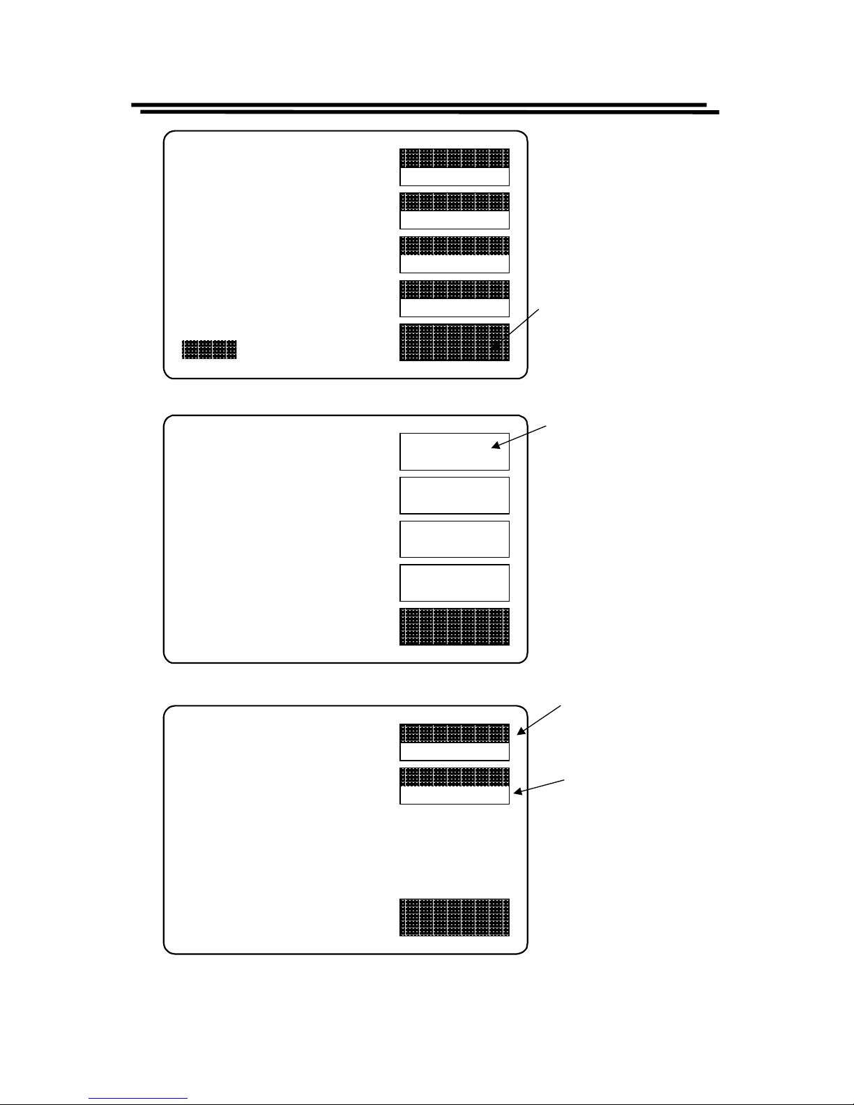
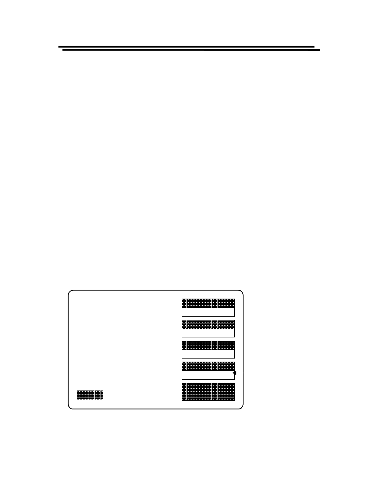
For the summary, the zeroing menu can be chosen through menu selection as
shown i n Fi gure 4-1 above.
NOTE: The “Open Circuit” and “Short Circuit” have to pass the test,
otherwise, the accuracy of the LCR Meters will become worse.
Page 14
LCR-800 Series User Manual
10
SPEED
SLOW
DISPLAY
VALUE
MODE
L/Q
CIRCUIT
SERIES
MENU
L 1.2345H
Q 0.6789
TESTING
F : 1.000 kHz
V : 1.000 V
AUTO MANU INT.B OFF
R.H OFF
C.V OFF
OFFSET
SORT
SETTING
CALBRAT
EXIT
CAP. R/L OFFSET
SET SORT
SET PARAMETER
CALIBRATION
Press menu
key
Press F1 key
to the zeroing
menu
EXIT
OPEN TEST
SHORT TEST
CAP
OFFSET
R/L
OFFSET
Press F1 KEY for
open test
Press
F2
KEY for
short test
Figure 4-1: Summary of zeroing menu
Page 15
LCR-800 Series User Manual
11
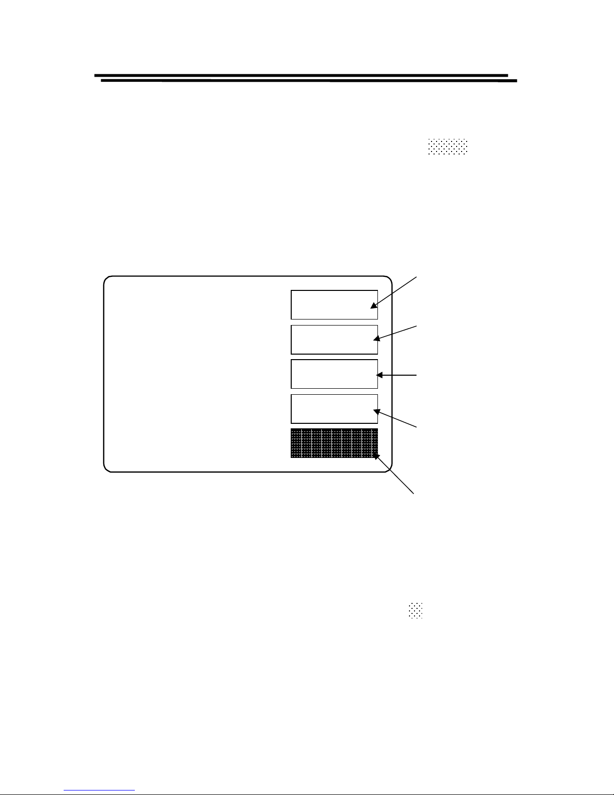
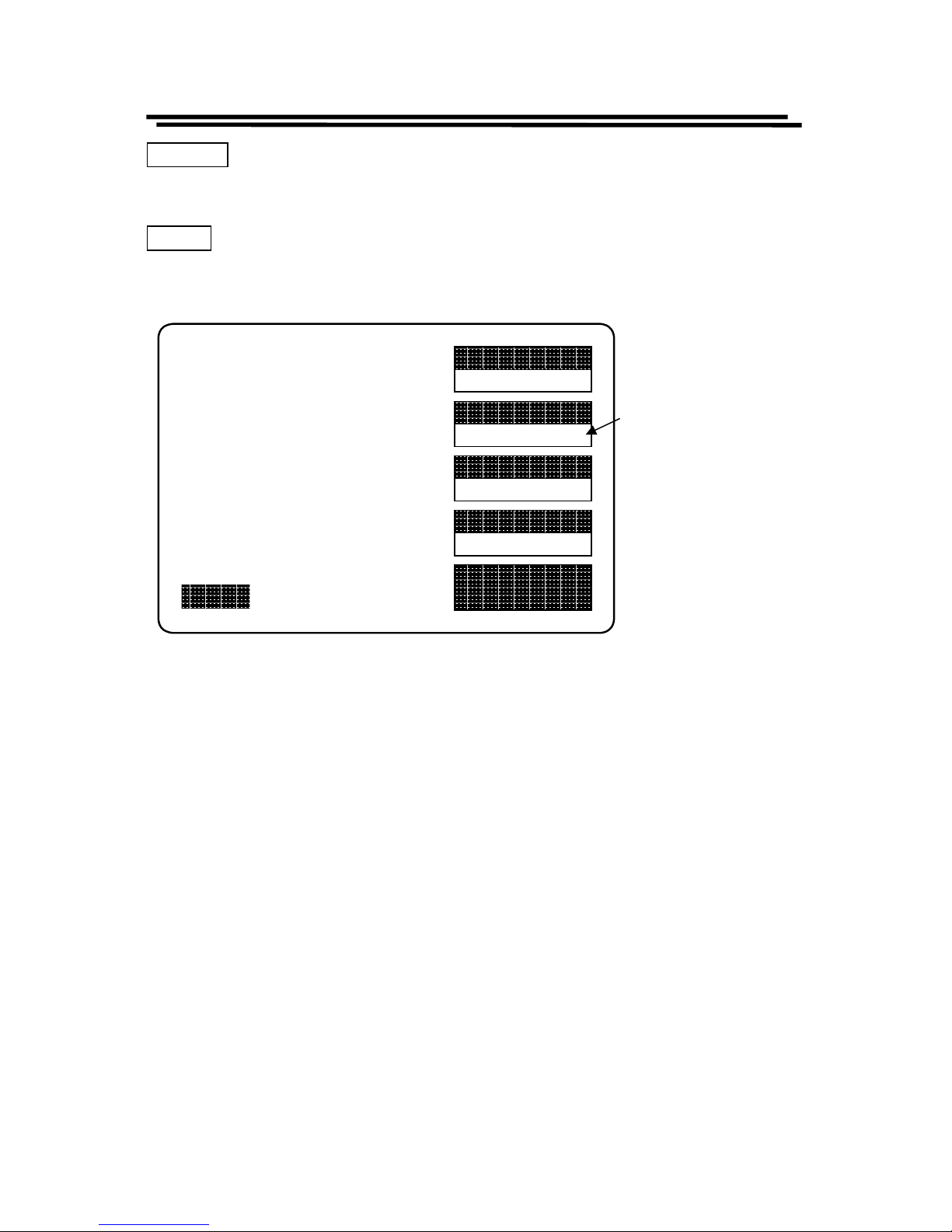
4-4. Menu Functions
All the LCR Meters’ programmable functions are controlled by the easy to use
menu displays. User can enter the menu mode by selecting the
MENU key that
calls up four top level menus, OFFSET, SORT, SETTING and CALBRAT.
Each one of these is comprised of a sub menu list whose functions are described
in detail below. User can enter one of four functions by pressing the
corresponding function key (just adjacent LCD monitor, see figure 4-2).
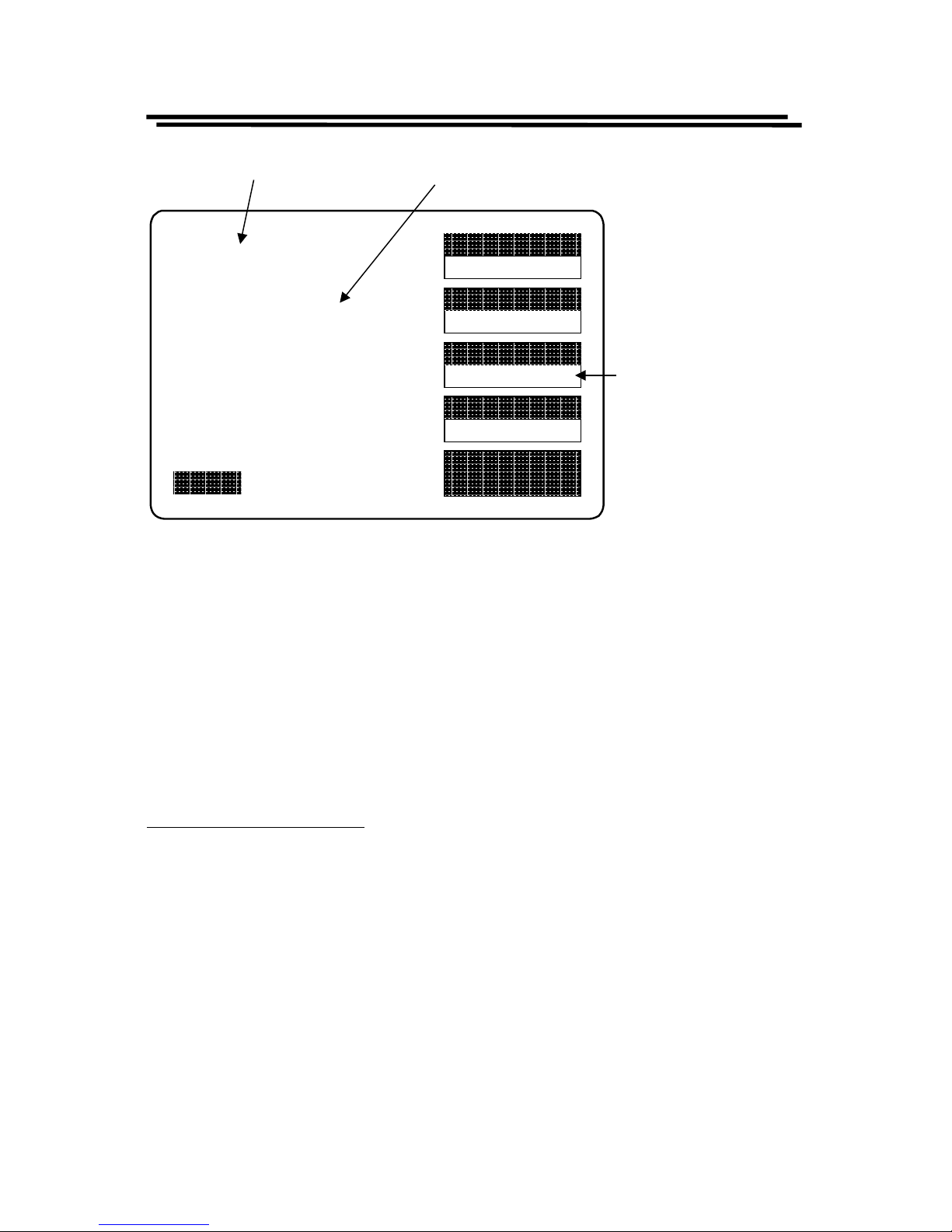
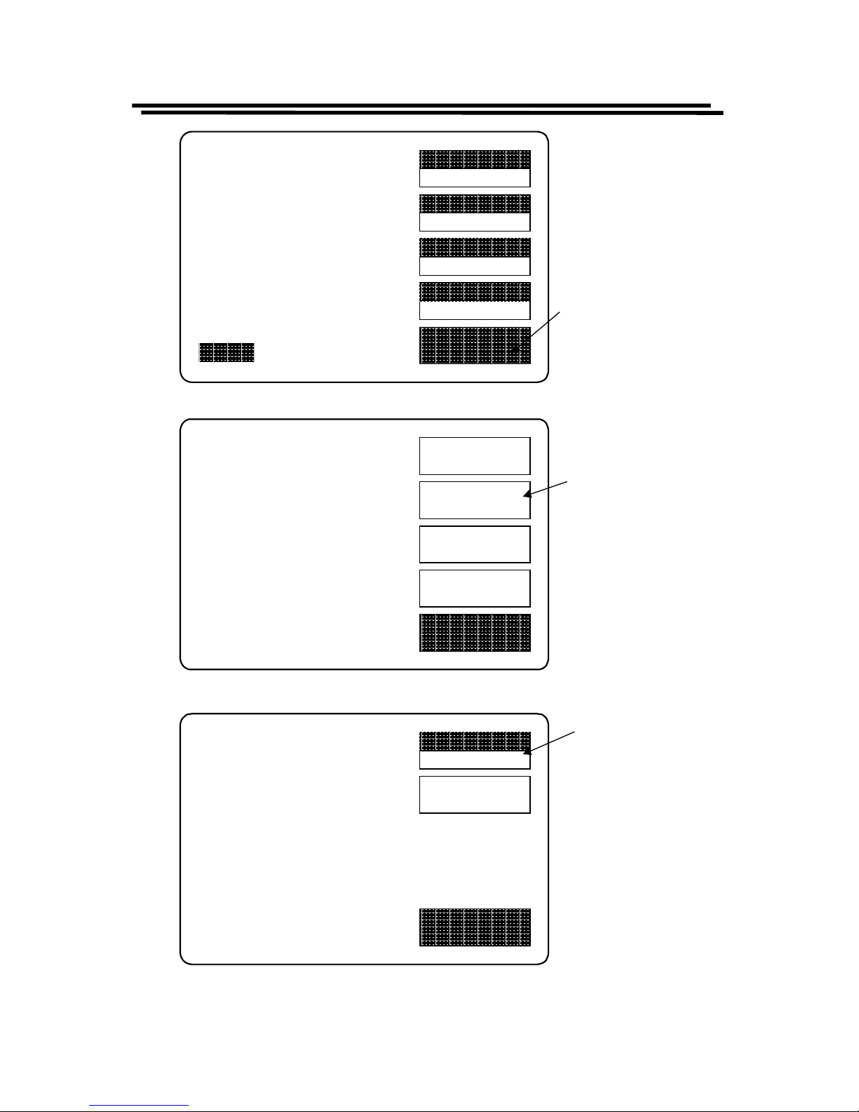
4-4-1. Primary & Secondary Display
For the LCR Meters, four combinations of two parameters can be measured and
displayed simultaneously. One referred to the “Primary Display” (displayed
fir st) and the oth er t o the “Secondary Display”. Depen ding on the com ponen t
type t he primar y and secondar y displ ay could be L & Q, C & D, C & R or R
and Q. The parameter can be chosen by the user through
F3 key as shown in
Figure 4-3.
OFFSET
SORT
SETTING
CALBRAT
EXIT
CAP. R/L OFFSET
SET SORT
SET PARAMETER
CALIBRATION
Press F1 key
to the zeroing
menu
Press F2 key
to the bin sort
menu
Press F3 key
to the utility
menu
Press F4 key
to the
calibration
menu
Press
MENU
key
to exit menu screen
Figure 4-2: four main menu screen
Page 16
LCR-800 Series User Manual
12
SPEED
SLOW
DISPLAY
VALUE
MODE
L/Q
CIRCUIT
SERIES
MENU
L 1.2345H
Q 0.6789
TESTING
F : 1.000 kHz
V : 1.000 V
AUTO MANU INT.B OFF
R.H OFF
C.V OFF
Press F3 key
successively in order
to select the different
measurement mode
(L/Q, C/D, C/Q, R/Q)
Primary
Display
Secondary
Display
Figure 4-3. Primary & Secondary display
User can select R/Q for resistor measurement; select L/Q for inductor
meas uremen t; select either C/D or C/R for capaci tor measuremen t.
4-4-2. Series & Parallel Equivalent Circuit
Impedance that is neither a pure resistance nor a pure reactance can be
repr esen t ed at an y speci fic fr eq uen c y by either a s eri es or a p aral lel combi n at ion
of resistance and reactance. Such repr esentation is called “equivalent circuit”.
The component value of the “Primary Display” depends on which equivalent
circuit (series or parallel) is chosen. In normal, the component manufacturer
shall specify how a component is to be measured (usually ser ies) and at what
frequency.
Suggested Test Conditions:
Inductors le s s t han 10µH: Series, 100kHz.
Inductors from 1 0 µH to 1mH: Series, 10kHz.
Inductors from 1mH to 1H: Se ries, 1kHz .
Inductors greater than 1H: S eri es, 0.1k Hz.
Capacitors less than 10pF: Parallel, 100kHz.
Capacitors from 10 to 400pF: Series or Parallel, 10kHz.
Capacitors from 400 to 1µF: Series, 1 kHz.
Capacitors greater than 1µF: Series, 0.1 or 0.12kHz.
Resistor less than 1kΩ: Series, 1kHz.
Resistor from 1kΩ to 10MΩ: Parallel, 0.25kHz.
Resistor greater th an 10 MΩ: Parallel, 0.03kHz
Page 17
LCR-800 Series User Manual
13
Unless for special reason, always select “Series” for capacitors and inductors.
This has traditionally been standard practice. For very small capacitance or
inductance, select a higher test frequency for better accuracy. For very large
capa citance or ind uctance, select a lower test fr equency for better accur acy. For
dc r esistance, select a l ower test frequency to minimize ac effects .
Becau se th e r eactive component most lik ely to be represented in a low resi s tance
resi stor is series ind uctance, th e “Seri es” is sel ected for a resist or below about
1kΩ. If a resistor large than 10MΩ, select “Parallel” that because the reactive
component most likely to be represent in a high resistance resistor is shunt
capa citan ce. If th e Q is less th an 0.1 , the mea sured Rp is proba bly ver y cl ose to
the d c r es istan ce.
The total loss of a capacitor can be expressed in several ways, including D and
“ESR” (Equivalent Series Resistance). “ESR” is typically much larger than
actu al “ohm ic” s er ies r esi stan ce of th e wir e l ead s and foil s th at ar e in ser ies wit h
the heart of a capacitor physically, because ESR includes also the effect of
dielectric loss. ESR is related to D by the formula: ESR = Rs = D/ωCs. Wher e ω
represents “omeg a” = 2 p i time freq u ency.
Although it is traditional to measure series inductance of inductors, there are
situation s in which the parallel equivalent circuit better represents the physical
component. For small “air-core” inductors, the significant loss mechanism is
usually “ohmic” or “copper loss” in the wire, therefore the series circuit is
appr opr iat e. Never th el ess, for an “ir on cor e” , th e sign i fican t loss mech an is m can
be “core loss”, therefore, the parallel equivalent circuit is appropriate which
being a better model of the inductor.
SPEED
SLOW
DISPLAY
VALUE
MODE
L/Q
CIRCUIT
SERIES
MENU
L 1.2345H
Q 0.6789
TESTING
F : 1.000 kHz
V : 1.000 V
AUTO MANU INT.B OFF
R.H OFF
C.V OFF
Press F4 key to
select the
Series
or
Parallel
circuit
Figure 4 -4. Sel ecti ons of S erie s & Parallel Circui t
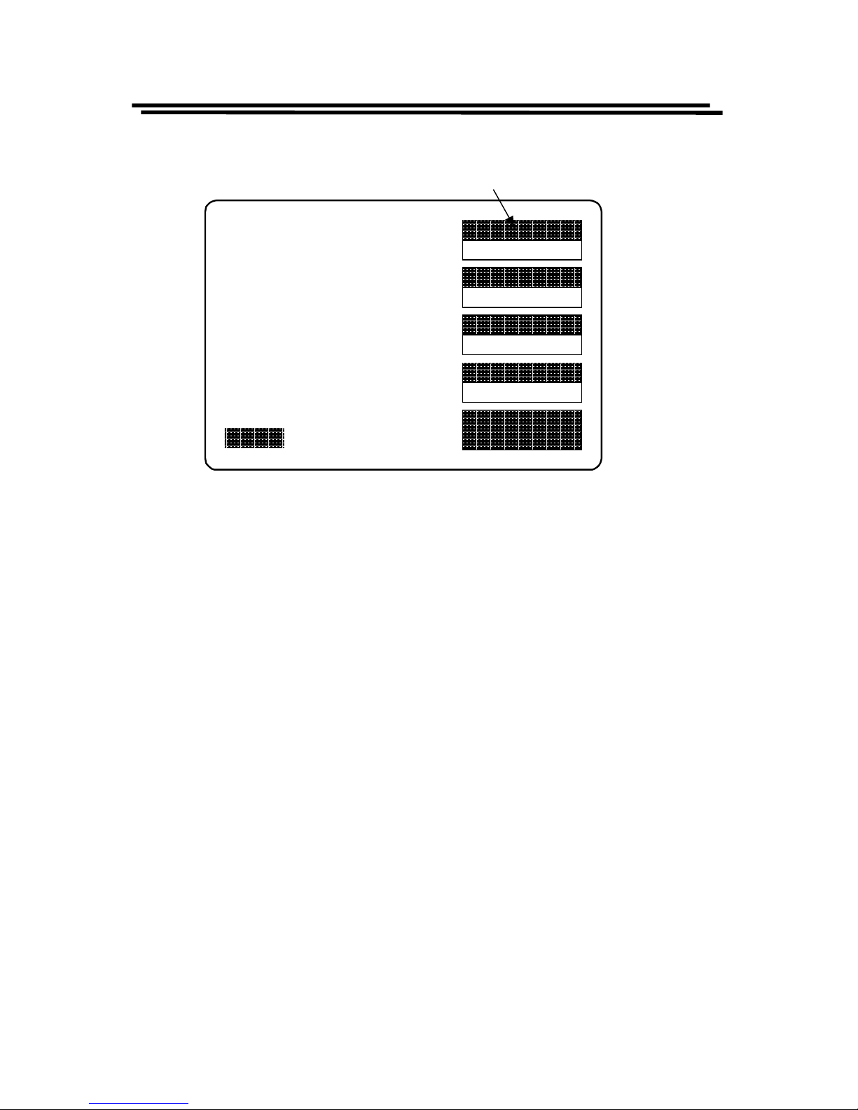
4-4-3. Measur em ent Displ ays
Page 18

LCR-800 Series User Manual
14
The measured results of the LCR Meters can be shown on the LCD monitor in
thr e e wa ys: VAL UE
, DELTA%, or DELTA . User can pres s F2 key to select the
appropriate it em for mea s uremen t.
VALUE
The LCD monitor will display the measured value of both the primary and
secondary parameter, shown with decimal and units. The resolution of primary
display (L, C, or R) is five digits. The resolution of secondary display (D, Q or R
with C) is four digits. The message “TESTING” is displayed when a test is in
process.
Page 19
LCR-800 Series User Manual
15
DELTA%
The “DE LTA%” shows th e percen t deviation of the measur ed L, C, or R va lue
from a stored N O MINAL VALUE. The sign of devi at ion is indic at e d.
DELTA
The LCR differ en ce is similar to th e DELTA% except tha t the d evia t ion is shown
in suitable units (ohms, henries, etc).
SPEED
SLOW
DISPLAY
VALUE
MODE
L/Q
CIRCUIT
SERIES
MENU
L 1.2345H
Q 0.6789
TESTING
F : 1.000 kHz
V : 1.000 V
AUTO MANU INT.B OFF
R.H OFF
C.V OFF
Press F2 key to select the
three different measuring
display ("VALUE",
"DELTA%", or "DELTA").
Figure 4-5. Types of measurement display
4-4-4. Nominal Value
Allows entry of a “Nominal Value” for the primary parameter which is the basis
for th e measur ement result in “DELTA” or “DELTA %”. A ccept s n umer ica l entry
up to five digits with decimal. Units are depended on which measurement
disp lays selected.
Page 20

LCR-800 Series User Manual
16
Steps of “Nom in al Value” in p ut (Figur e 4- 6 ):
! Press MENU key.
! Press F2 key to select “SORT” menu.
! Press F1 key to select “Nominal Value” (the “NOM.VAL” is indicated on
the adjacent LCD m on itor).
! Input the nominal value via the numeral keys (5 digits with decimal
maximum).
! Press ↵
↵↵
↵ key
! After the BAR at the bottom of LCD monitor is filled fully, the “Nominal
Value” input is done.
4-4-5. Selection of Measurement Speed
One of three measurement speeds SLOW, MEDIUM, or FAST could be
selected (Figure 4-7). The continuous mode speeds are about 1, 5, and 12
meas urement per second resp ectivel y. Th e trade-off is a ccuracy vs. speed. LC R817/819 will take a more accurate measurement at a slower rate. The trade-off is
as follows section
SLOW
speed : More than 1 mea surement per second, at 0.05% accur acy ( or
better)
MEDIUM
speed : More than 3 measurements per second, at 0.1% accuracy
(or better)
FAST
speed :
More than 7 measurements per second, at 0.24% accuracy
(or better)
* For th e d etails of a ccu ra cy, please refer to the specifica tions.
* Regarding the models LCR-827 & 829, please refer to 4-6-2 Handler Interface
Timing.
Page 21
LCR-800 Series User Manual
17
SPEED
SLOW
DISPLAY
VALUE
MODE
L/Q
CIRCUIT
SERIES
MENU
L 1.2345H
Q 0.6789
TESTING
F : 1.000 kHz
V : 1.000 V
AUTO MANU INT.B OFF
R.H OFF
C.V OFF
OFFSET
SORT
SETTING
CALBRAT
EXIT
CAP. R/L OFFSET
SET SORT
SET PARAMETER
CALIBRATION
Press menu
key
Press F2 key
to the sort
menu
NOM.VAL
24.870
HANDLER
EXIT
NOM.VAL = 77.000pF
OPTION 1
Press F1 key to
input the
nominal value
Figure 4-6. Steps of “Nominal Value” input.
Page 22
LCR-800 Series User Manual
18
SPEED
SLOW
DISPLAY
VALUE
MODE
L/Q
CIRCUIT
SERIES
MENU
L 1.2345H
Q 0.6789
TESTING
F : 1.000 kHz
V : 1.000 V
AUTO MANU INT.B OFF
R.H OFF
C.V OFF
Press
F1
key to select the three different measurement
speed. (SLOW, MEDIUM, or FAST)
Figure 4-7. Selection of measurement speed
4-5. Measurement Conditions
4-5-1. Bias Vo ltage
There are two ava ila bl e bi as volt age modes: “Internal” and “External”.
Internal:
An internal DC 2 volts bias voltage will apply to the device under test.
External:
An ex t er n al DC bi a s vol t a g e bet we en 0 a nd 30 volt s can be a ppl i ed t o t h e d evi ce
under test. The external bias connection is located on the rear panel. The
maximum current is 200mA. The supply of bias voltage has to be floating, don’t
connect either side to ground. It’s better to wait approximately 1 second for
takin g a read ing aft er init iatin g a test ing pr ocess, th erefor e, th e device u nder t est
will stabilize after bias voltage applied. The DC bias voltage should be applied
only to capacitors in general. If the DC bias voltage is applied to device of low
impedance, the unreliable testing results will occur.
Page 23

LCR-800 Series User Manual
19
SPEED
SLOW
DISPLAY
VALUE
MODE
L/Q
CIRCUIT
SERIES
MENU
L 1.2345H
Q 0.6789
TESTING
F : 1.000 kHz
V : 1.000 V
AUTO MANU INT.B OFF
R.H OFF
C.V OFF
Press the numerical 7 key
to select either internal or
external bias voltage
Press the numerical 8 key to
turn either internal or external
bias voltage on or off.
0
R.H
.
_
FREQ
1
C.V
2 3
4
PPM
5 6
7
BIAS
8
ON/OFF
9
S
T
A
R
T
Indication of internal or
external bias voltage
Figure 4-8. Selection of “BIAS” voltage
Page 24

LCR-800 Series User Manual
20
Steps of “BIAS” voltage selection (Figure 4-8, please note that the models of
LCR-816 and 826 do not have this function):
! Press compoun d key 7 to selects the “INTE RNAL BIAS” or “EXTE RNAL
BIAS” on the main menu. (If this key function is switched to “INTERNAL
BIAS”, the bottom of LCD monitor will display the “INT.B” message. If
the external DC bias is selected, the bottom of LCD monitor will display the
“EXT.B” message.
! Press compoun d key 8 to turn either “INTERNAL BIAS” or “EXTERNAL
BIAS” mode “ON” or “OFF” on the main men u.
4-5-2. Test Frequency
The numerical input of test frequency accepts up to 5 digits with decimal. User
can input any desired frequencies, however, the actual frequency executed for the
LCR Meter s is always th e closest one of th e 503 a vai lable frequ enci es. Th e 503
frequ enci es can be calculated by th e fol l owin g for mula s :
3kHz/n, where n range is from 13 to 250 (freq. 0.012 to 0.23077kHz)
60kHz/n, where n range is from 4 to 256 (fr eq. 0.23438 to 15kHz)
200kHz/n, where n range is from 2 to 13 (freq. 15.385 to 100kHz)
The “n ominal va lue” of an ava ila bl e freq uen cy can be ca lcu lat ed from th e prop er
one of the three formu las.
The range of test frequency between 12Hz and 10kHz is for LCR-817/827,
between 12Hz and 100kHz for LCR-819/829, and between 100Hz and 2kHz for
LCR-816/826. To select the test frequency, just key in the desired frequency via
these numerical keys, the LCR Meters will take the nearest available test
frequency from the 503 available test frequencies automatically.
Steps of “Test Frequen cy” select ion (Figure 4-9):
! Press compoun d key FREQ.
! Input the desired frequency in kilohertz.
! Press ↵
↵↵
↵ key.
Note: After test frequency has been changed, the zeroing of “Open/Short
circuit” must be done again for the best accuracy.
Page 25

LCR-800 Series User Manual
21
SPEED
SLOW
DISPLAY
VALUE
MODE
L/Q
CIRCUIT
SERIES
MENU
L 1.2345H
Q 0.6789
TESTING
F : 1.000 kHz
V : 1.000 V
AUTO MANU INT.B OFF
R.H OFF
C.V OFF
Press - key to input test
frequency
Press enter key to confirm the
inputs.
0
R.H
.
_
FREQ
1
C.V
2 3
4
PPM
5 6
7
BIAS
8
ON/OFF
9
S
T
A
R
T
test frequency
Figure 4-9. Inputs of test frequency
Page 26

LCR-800 Series User Manual
22
4-5-3. D/Q in PPM (parts per million)
If the value of D or Q is less than 0.0100, user can select DQ in PPM to improve
the resolution by a factor of 100. The units of D and Q in PPM are dimensionless
and expressed as a decimal ratio with the multiplier of 1000000. User can just
press compound key
4 to select th e unit of D or Q in PPM. To disabl e the DQ in
PPM feature, press the same key again.
4-5-4. Test Voltage
The range of test voltage is from 5mV to 1.275V in increments of 5mV. The
actual voltage through the DUT is never more than the source voltage. The DUT
impedance and the source resistance of the LCR Meters decide the actual test
voltage. The smallest voltage through the DUT will be 20% smaller of the source
voltage in general. The programming of test voltage is as follows (Figure 4-10):
! Press MENU key.
! Press F3 key to select “SETTING” menu.
! Press F2 key to select “VOLT” menu.
! In put the desi red val ue via the numer al keys.
! Press ↵
↵↵
↵ key
! After the BAR at the bottom of LCD monitor is filled fully, the “Test
Voltage” input is done.
4-5-5. Constant Voltage Source
If the DUT have to be measured at a particular test voltage, the LCR Meters
provides th e constant volt age feature. Aft er “Constan t Voltage” is sel ected, The
LCR Meters will keep a source resistance of 25Ω. Therefore, the test voltage is
const an t for an y DUT imped an ce which larg e than 2 5Ω. If “C onstant Vol tage” is
selected, the measurement accuracy will cause a reduction by a factor of three.
User can just pr ess compoun d key
1 to select the feat ure of “Con stant Voltag e”.
To disable this feat ure, pr es s the sam e ke y ag ain.
Page 27

LCR-800 Series User Manual
23
SPEED
SLOW
DISPLAY
VALUE
MODE
L/Q
CIRCUIT
SERIES
MENU
L 1.2345H
Q 0.6789
TESTING
F : 1.000 kHz
V : 1.000 V
AUTO MANU
R.H OFF
C.V OFF
INT.B OFF
OFFSET
SORT
SETTING
CALBRAT
EXIT
CAP. R/L OFFSET
SET SORT
SET PARAMETER
CALIBRATION
Press menu
key
Press F3 key
to the setting
menu
MOMORY
1
VOLT
1.000
AVGE
1
EXIT
MOMORY NO: 1
VOLTAGE = 1.000 V
AVERAGE = 1
Press F2 key to
input the desired
test voltage
Test Voltage
Figure 4-10. Programming of test voltage.
Page 28

LCR-800 Series User Manual
24
4-5-6. Range Hold
If a DUT is removed from the test cable or fixture during the “Continuous”
mode, the feature of “Range Hold” can avoid range switching. Due to the test
time can be reduced, “Range Hold” is a useful utility for repetitive devices
meas uremen t. User can just press com p ound key
0 to select the feat ure of “Ra nge
Hold”. To disable this feature, press the same key again.
4-5-7. Averaging
If this function is enable, the testing time will multiple by the number of tests
(from 1 to 255). Hence, the accuracy can be enhanced. The measurement time
will be increased to the contrary. The programming of “Averaging” is as follows
(Figure 4-11):
! Press MENU key.
! Press F3 key to select “SETTING” menu.
! Press F3 key to sele ct “AVGE” menu.
! In put the desi red val ue via the numer al keys.
! Press ↵
↵↵
↵ key
! After the BAR at the bottom of LCD monitor is filled to the full, the
“Averaging” input is done.
Page 29

LCR-800 Series User Manual
25
SPEED
SLOW
DISPLAY
VALUE
MODE
L/Q
CIRCUIT
SERIES
MENU
L 1.2345H
Q 0.6789
TESTING
F : 1.000 kHz
V : 1.000 V
AUTO MANU
R.H OFF
C.V OFF
INT.B OFF
OFFSET
SORT
SETTING
CALBRAT
EXIT
CAP. R/L OFFSET
SET SORT
SET PARAMETER
CALIBRATION
Press menu
key
Press F3 key
to the setting
menu
MOMORY
1
VOLT
1.000
AVGE
1
EXIT
MOMORY NO: 1
VOLTAGE = 1.000 V
AVERAGE = 1
Press F3 key to
input the desired
averaging amount
Figure 4-11. Programming of averaging.
Page 30

LCR-800 Series User Manual
26
4-5-8. Memory
The LCR Meters have two memory functions: Recall and Store. The current
measurement conditions can be saved into the memory unit or recalled a
previously saved measurement conditions set from the LCR Meters memory.
There are 100 memory blocks totally. The programming of “Memory Store /
Recall” can be used as described below (Figure 4-12):
! Press MENU key.
! Press F3 key to select “SETTING” menu.
! Press F1 key to select “MEMORY” menu.
! Press compoun d key 1 to recall a previously saved memory block. or
! Press compound key 2 to store the current measurement conditions into
memory.
! Input the number of desired memory block. (1~100)
! Press ↵
↵↵
↵ key
! After the BAR at the bottom of LCD monitor is filled to the full, the process
of “Memory Store/ Recal l” is d on e.
Remark: For LCR-827/829, the function of Recall and Store is not only used in
the norm al memory sta tus, als o it can be exten ded to sortin g and BINSUM setting.
Page 31

LCR-800 Series User Manual
27
SPEED
SLOW
DISPLAY
VALUE
MODE
L/Q
CIRCUIT
SERIES
MENU
L 1.2345H
Q 0.6789
TESTING
F : 1.000 kHz
V : 1.000 V
AUTO MANU
R.H OFF
C.V OFF
INT.B OFF
OFFSET
SORT
SETTING
CALBRAT
EXIT
CAP. R/L OFFSET
SET SORT
SET PARAMETER
CALIBRATION
Press menu
key
Press F3 key
to the setting
menu
MOMORY
1
VOLT
1.000
AVGE
1
EXIT
MOMORY NO: 1
VOLTAGE = 1.000 V
AVERAGE = 1
Press F1 key to
select the memory
store/recall function
Figure 4-12. Programming of memory store/recall.
Page 32

LCR-800 Series User Manual
28
MOMORY
1
VOLT
1.000
AVGE
1
EXIT
STORE NO:
VOLTAGE = 1.000 V
AVERAGE = 1
MOMORY
1
VOLT
1.000
AVGE
1
EXIT
(1)RECALL:(2)STORE
VOLTAGE = 1.000 V
AVERAGE = 1
Press compound key 1 to select
the memory recall function
MOMORY
1
VOLT
1.000
AVGE
1
EXIT
RECALL NO:
VOLTAGE = 1.000 V
AVERAGE = 1
Input number of desired memory block for memory recall function
Press compound key 2 to select
the memory store function
Input number of desired memory block for memory store function
Figure 4-12. Programming of memory store/recall. (Cont.)
Page 33

LCR-800 Series User Manual
29
4-5-9. Handler Interface(Only for LCR-826/827/829)
HANDLER
INTERFACEFUNCTION
Signal Name Pin NO.
Start M easurement ( I) /I_ E_TRIG 24
End of test(O) /O_EOM 23
Data acquisition over , DUT removal OK.(O) /O_INDEX 22
RLC FAIL(O) /O_P_HI
/O_P_LO
/O_P_OVER
19
20
15
No-Go , D or Q Fa il /O_S_ REJ
/O_S_OVER
21
14
Go , BIN 1 Judgement /O_BIN_ 1 1
Go , BIN 2 Judgement /O_BIN _2 2
Go , BIN 3 Judgement /O_BIN_ 3 3
Go , BIN 4 Judgement /O_BIN_ 4 4
Go , BIN 5 Judgement /O_BIN_ 5 5
Go , BIN 6 Judgement /O_BIN_ 6 6
Go , BIN 7 Judgement /O_BIN_ 7 7
Go , BIN 8 Judgement /O_BIN_ 8 8
Go , BIN 9 Judgement /O_BIN_ 9 9
Go , BIN 10 Judgement /O_BIN_ 10 10
Go , BIN 11 Judgement /O_BIN_ 11 11
Go , BIN 12 Judgement /O_BIN_ 12 12
Go , BIN 13 Judgement /O_BIN_ 13 13
Panel Lock /I_K_LOCK 25
GND GND 16,18
VCC VCC 17
Ha n d ler I nterface Typical El ect ric al Ch arac ter ist i cs
Comparison Signals Voltage Output Rating Maximum Current Note
Page 34

LCR-800 Series User Manual
30
Low High
/BIN1-/BIN9
/AUX_BIN
/OUT_OF_BIN
**
/PHI
0.5V +5V+24V
5mA
/PLO
Control Signals
/INDEX
/EOM
* R408R427 Pull-high Resistor need to be changed.
Ha n d ler I nterface Typical El ect ric al Ch arac ter ist i cs
Input
Input Current (Low)
Pull- h igh Voltage
Note
Comparison Signals
Low High +5V +12V
/EXT_TRIG
1V 5V15V
5mA 12mA
/KEY_LOCK
1V 5V15V
5mA 12mA
! Input Signals
/I_E_TRIG: This signal is a measurement start signal. To start
measurement by setting low pulse to minimum 5us for
/I_E_TRIG signal. This is a low edge active.
/I_K_LOCK: This signal is to lock all front panel controls. The front panel
is disable when /I_K_LOCK is at low level, and enable
when /I_K_LOCK is at hig h leve l.
Page 35

LCR-800 Series User Manual
31
! Measurement Complete signal:
/O_INDEX: This signal will go the low level when analog measurement is
completed and will go the high level when next trigger is
active. The handler can then rem ove t he DUT from the fi x ture
and replace it with another DUT during the time when
/O_INDEX is at low level.
! Compare Output Signals:
/O_BIN_1- /O_BIN_13 : The GO judgment is active according to the
measured value judgment results (low level),
for example, if the comparator assigns a
component to BIN1, the /O_BIN_1 line will go
the low level till T4 (see Handler Interface
Timing). /O_BIN_2 - /O_BIN_13 are all
inactive (high level).
/O_P_HI: Main parameter failure: When the main parameter is greater than
Max, it will go the low level till T4 (see Handler Interface
Timing).
/O_P_LO: Main parameter failure: Wh en the main parameter is lower than
Min, it will go the low level till T4(see Handler Interface
Timing).
/O_P_OVER: It will go the low level when main parameter is greater than
Max or is low er than Min.
/O_S_REJ,/O_S_OVER: It will go the low level when secondary is greater
than D_Max (if MODE=C/D) or is lower than
D_Min.
! Judgment Complet e Si g nal
/O_EOM: This signal becomes active (low level) when the measurement
and comparator judgment are completed, and all handler
interface output are stable. It will go the high level when next
trigger Signal (/I_E_TRIG) becomes active (low edge).
Page 36

LCR-800 Series User Manual
32
Page 37

LCR-800 Series User Manual
33
4-5-10. Handler Interface Timing(only for LCR-826/827/829)
Page 38

LCR-800 Series User Manual
34
Time Minimum
Value
Maximum
Value
T1 Trigger Pulse Width 5 us
T2 Measurement Start
Delay Time
140 us
T3 /EOM De lay Time
After Data O utput
5 us
T4 Calculation and
binning Time
6 ms
SPEED Analog Measurement Time(T5)
Tr igg er Wait T ime
After /EOM
Output (T6)
0.012kHz 0.1kHz 0.12kHz 1kHz 10kHz 100kHz OFF BIN VALUE
SLOW 817ms 901ms 901ms 903ms 873ms 873ms 2ms 4ms 16ms
MEDIUM 817ms 125ms 105ms 59ms 53ms 53ms 2ms 4ms 16ms
FAST 817ms 125ms 103ms 27ms 17ms 17ms 2ms 4ms 16ms
ACCURACY
MODEL
FAST MEDIUM SLOW
LCR-827
LCR-829
LCR-826
0.5% 0.2% 0.1%
* DATA: /O_BIN_1-_BIN_13,/O_P_OVER,/O_S_OVER,/O_S_REJ,/O_P_HI,/O_P_LO
Page 39

LCR-800 Series User Manual
35
5. SPECIFICATIONS
Measurement Parameters:
Inductance (L
s/Lp
)*, Capacitance (Cs/Cp), Resistance (Rs/Rp), Dissipation (D),
Quality Factors (Q), Equivalent Series Resistance (ESR) and Equivalent Parallel
Resistan ce (E PR).
Measurem en t Models:
Four kinds of measurement model can be selected. Two measurement
parameters measured and displayed simultaneously.
R/Q, C/D, C/R, L/Q
Display Ra nges:
Primary Display
Inductance (L) : 0.00001mH
99999H
Capacitance (C) : 0.00001pF
99999F
Resistan ce (R) :
0.0000199999k
Secondary Display
Dis sipat ion fact or (D)
+
: 0.0001
9999
Quality factor ( Q)
***
: 0.0001
9999
Equ ivalent Seri es Resi s tan ce ( ESR)
+
:
0.00019999 k
Equivalent Parallel Resistance (EPR)
+
:
0.00019999 k
Dis sipat ion fact or (D)
+
in ppm : 1 ppm
9999 ppm
Quality factor ( Q)
**
in ppm : 1 ppm
9999 ppm
DELTA % : 0.00001%
99999%
If any of these quantities is negative, the “-“ negative indicator is displayed
*
s=seri es, p = para l lel, ESR=Rs ** with R
***
with L or R + wit h C
Page 40

LCR-800 Series User Manual
36
Accuracy:
R, L, C: 0.0 5% (Basi c )
+
D, Q: 0.0005 (Basic)
+
*LCR-816/826/827/829 is one fold less accuracy than LCR-817/819.
(LCR-816/826: 0.2%, LCR-827/829: 0.1%, LCR-817/819: 0.05%)
Test Fr equency:
There are 503 test frequencies between 12Hz and 100kHz that can be selected
by using keypad for LCR-819/829. The frequency range of LCR-817/827
covers from 12Hz to 10kHz, LCR-816/826 covers from 100Hz to 2kHz.
Measurement Di splays:
The measured results can be shown on the LCD monitor in four ways:
1. VALUE
:
The measured quantities of R/Q, C/D, C/R, or L/ Q.
*The resolution of primary display (L, C, or R) is five digits.
*The resolution of secondary display (D, Q or R with C) is four
digits.
2. DELTA
:
The LCR difference is similar to the DELTA% except that the
deviation is shown in suitable units (ohms, henries, etc.)
3. DELTA %
:
The DELTA% shows the percent deviation of the measured L,
C, or R value from a saved NOMINAL VALUE. The sign of
deviation is indicated.
Measurement Speed (LCR-816/817/819):
SLOW
MEDI
FAST
:
:
:
896ms
286ms
135ms
*For LCR-826/827/829, please refer to 4-5-10. Handler Interface Timing.
Eq uivalen t Ci rc uit :
The L, C, or R equivalent SERIES or PARALLEL circuit can be selected by
keypad.
+
Please refer to page41~43 for details.
Page 41

LCR-800 Series User Manual
37
Measurem ent Mod es :
Two modes are availa bl e: AUTO and M A NUAL.
“AUTO” mode is measuring continuously, updating the display after each
measurement.
“MANUAL” mode is activated by the START keypad, the measured result is
holding on the LCD monitor until next measurement started.
Average:
Th e AVERA GE of an y num ber of meas ure men ts fr om 1 t o 255 can be ma de as
desired in either of the two measurement modes.
In “AUTO” mode, only the final value is shown.
In “MANUAL” mode, the runnin g average is shown and the final value held
until the START keypad is depressed again.
Test Voltage:
The test voltage range for LCR-817/819/827/829 is from 5mV to 1.275V, each
step is 5mV, for LCR-816/826 is from 0.1V to 1.275V, each step is 5mV.
Memory:
100 memory blocks totally.
DC Bias:
A 2V int ern al bias can apply to ca p acit ors during mea surement.
Up to 30V DC ex tern al bia s can apply t o ca pa ci tor s d ur ing mea sur em ent via th e
two terminals (located on the rear panel). The applied current should not over
200mA.
LCD monitor:
240×128 dot matrix C.C.F.L. back light LCD with adjustable contrast.
Battery:
DC source for system memory and calibration data backup, a replaceable 3V
li thi um bat ter y (BR-2/ 3A type) whi ch pr obabl y n eeds to be r ep lace d a fter usin g
for 3 yea rs .
After the battery is replaced, the LCR Meters have to be re-calibrated!
Page 42

LCR-800 Series User Manual
38
Operation Environment:
Indoor us e,
Altitude up to 2000M
Installation Category II
Pollution Degree 2
Oper atin g t empera ture: 1 050, < 85% relative hum i dity
Storage temperature:2060
AC Power Source:
AC 100240V, 50Hz60Hz
Power Consumption:
45 Watts maximum
Fuse Replacement:
Slow-Blow, 3A, 250V
Dimensions:
330mm (W) × 149mm (H) × 437mm (D)
Weight:
5.5 kg
Page 43

LCR-800 Series User Manual
39
The Error value of LCR-817/819 (Double the error value for LCR-827/829,
4 times the error value for LCR-816/826)
! The formula for primary read out accuracy of C, R, and L.
C: 0.03% + 0.02% [ (1+K a)# or (X/Ymax )# or (Ymi n/X)# ] (1+D)(1+Kb+Kc)
R: 0.03% + 0.02% [ (1+K a)
#
or (X/Ymax )# or (Ymi n/X)# ] (1+Q)(1+Kb+Kc)
L: 0.03% + 0.02% [ ( 1+Ka)
#
or (X/Ymax )# or (Ymin/X )# ] (1+ 1 /Q)(1+Kb+Kc)
! Th e formu las of secondary read ou t accuracy for D and Q.
Error
D with C
2count±0.0003 + 0.000 2[(1+Ka)
#
or (X/Ymax) # or (Ymi n/X)
#
] (1+D+D×D)(1+Kb+Kc)
Q with R
2count±0.0003 + 0.000 2[(1+Ka)
#
or (X/Ymax) # or (Ym in/X)
#
] (1+Q+Q×Q)(1+Kb+Kc)
Q with L
2count±0.0003 + 0.000 2[(1+Ka)
#
or (X/Ymax) # or (Ym in/X)
#
] (1+Q+Q×Q)(1+Kb+Kc)
#: 1. if XYmax, please select (X/ Y m ax)
2. if XYmin, please select (Ym in/ X )
3. if Ymin<X<Ymax, please select (1+Ka)
! The for mula s for secon d ary rea dout accuracy of R wit h C.
Error
D1 2count + 0.02%[( 1+K a)* or (Rx/Rmax)* or (R min/R x)*] (1+ 1/D)(1+Kb+Kc)+0.03%
D1 2count + 0.02%[( 1+K a)** or (Cx/ Cmax)** or (C min/C x)**] (1+ 1/D)(1+Kb+Kc)+0.03%
*: 1. If RxRmax , plea se select (Rx/Rmax)
2. if RxRmin, please select (Rmin/Rx)
3. if Rmin<Rx<Rmax, please select (1+Ka)
**: 1. If CxCmax, please select (Cx/Cmax)
2. if CxCmin, pl ease sel ect (Cm in/ C x)
3. if Cmin<Cx<Cma x, ple a se se lect (1 +K a )
Where
Ka: Constant Voltage factor
Constant Voltage On , Ka = 2
Constant Voltage Off, Ka = 0
Kb: Test Speed factor
Speed = SLOW , Kb = 0
Speed = MEDIUM , Kb = 3
Speed = FAST ,Kb = 10
Page 44

LCR-800 Series User Manual
40
Kc: Frequency & RMS Voltage factor (re fe r to Table A)
X: X is va lue of th e co m p onent b eing tested.
Y: Y is range constant (refer to Table B)
Rx and Cx are value of the component being tested.
Rmax, Rmin, Cmax and Cmin are ranges constant (refer to Table B).
Table A: (for range 1,2,3) –Kc
Voltage
Frequency
0.03V0.1 0.1V0.25 0.25V11V1.265
0.012F0.03
35 12 9 7
0.030F0.1
30 8 5 3
0.1F0.25
25 6 3 2
0.25F1
20 5 2 1
114410
1F3
15 5 2 1
3F6
15 6 3 2
6F10
15 8 5 3
10F20
20 10 6 5
20F50
30 22 18 15
50F100
50 40 35 30
F: test frequency in kHz
Page 45

LCR-800 Series User Manual
41
Table A: (for range 4)-Kc
Voltage
Frequency
0.03V0.1 0.1V0.25 0.25V11V1.265
0.012F0.03
70 20 10 7
0.030F0.1
50 13 6 3
0.1F0.25
35 9 4 2
0.25F1
25 6 2 1
115410
1F3
17 6 3 2
3F6
25 15 10 6
6F10
60 30 20 15
10F20
Not specified 100 65 50
20F50
50F100
This range is not used above 20kHz
F: test frequency in kHz
Table B- 1: Ra nge Hold
Inductor Capacitor Resistor
Component
Range
Max Min Max Min Max Min
Range1 16mH /f 1mH /f 25uF /f 1.6uF /f
100 6.25
Range2 256mH /f 16mH /f 1600nF /f 100nF /f
1.6k 0.1k
Range3 4100mH /f 256mH /f 100nF /f 6.4nF /f
25.6k 1.6k
Range4* 65H/f 4.1H /f 6400pF /f 400pF /f
410k 25.6k
f = test frequency in kHz
*: This range is not used above 20kHz
Table B- 2: Auto Ra nge
Inductor Capacitor Resistor
Component
Range
Max Min Max Min Max Min
Auto range 65H /f** 1mH /f 25uF /f 400pF /f **
410k** 6.25**
**: Above 20kHz, Cmin = 6.4 nF/f ,and Lmax = 4100mH/f
Page 46

LCR-800 Series User Manual
42
6. MESSAGE CODE
This section describes the message code for the LCR Meters.
OVER-01
Cause:
1. If the impedance of “Device-under-test” is small than the existing
measurement range of the LCR Meters, the “OVER-01” message will be
displayed on the LCD monitor.
Calculation formula:
Capacitance: XC=1/2πfC
Inductance: XL=2πfL
wher e f=test freq u ency in Hz
2. If the inductor of “Device-under-test” is very large at a very high “test
frequency”, the “Resonance effect” will occur and the impedance will
decr ease. Hen ce, th e meas ured valu e is usel ess. Mean wh ile, an “OVE R-0 1”
message will be displayed on the LCD monitor.
Solution:
1. Turn on the “Constant Voltage” mode (please refer to 4-5-5. Constant
Voltage Source, page 22, for details).
2. Select the less m easuremen t rang e. Please refer to ta ble B-1: Range Hold,
page 42, in order to reach the exact measurement range. Turn on the “Range
Hold” mode after the measurement range fixed.
Note: Both two solutions will reduce the accuracy of the LCR Meters.
Page 47

LCR-800 Series User Manual
43
7. MAINTENANCE
This section includes the basic maintenance information for the LCR Meters.
7-1. Cleaning
Remove t he AC inp ut power (di sconnect and remove th e power cord ) fr om the
LCR Meters before attempting to clean the instrument.
To clear the LCR Meters, use soft cloth dampened in a solution of mild detergent
and water. Do not spray cleaner directly onto the instrument, since it may leak
int o the ca binet and cause dam age.
Do not use chemi cals conta ining benzin e, benz ene, xylen e, aceton e, tol uene, or
similar solvents.
Do not u s e abrasive cl ean ers on any portion of thi s equ ipment.
7-2. Battery Replacement
A replaceable 3V lithium battery (BR-2/3A type) supplies the backup power of
non-volatile memory for the LCR Meters. This battery probably needs to be
replaced after using for 3 years.
CAUTION: Danger of explosion if battery is incorrectly
replaced. Replace only with the same or equivalent type
recommended by the manufacturer. Discard used batteries
according to the manufacturer’s instructions.
Page 48

LCR-800 Series User Manual
44
8. OPTION 1BIN Functions, only for LCR-826/827/829
8-1. BIN FUNTIONS for Components Sorting :
Proceed BIN FUNTIO N S s tepsFigure 8-1:
! Press MENU key.
! Press F2 key to select “SORT” function.
! Press F2 key to sele ct “OPT I O N 1 ” fu nction .
Page 49

LCR-800 Series User Manual
45
SPEED
SLOW
DISPLAY
VALUE
MODE
C/D
CIRCUIT
SERIES
MENU
C 13.450uF
D .1652
TESTING
F :1.0000 kHz
V :1.000 V
AUTO MANU INT.B OFF
R.H OFF
C.V OFF
OFFSET
SORT
SETTING
CALBRAT
EXIT
CAP. C/D OFFSET
SET SORT
SET PARAMETER
CALIBRATION
Press menu
key
Press
F2
key
to the sort
menu
NOM.VAL
77.000
EXIT
NOM.VAL = 77.000pF
OPTION1
Press
F2
key to
input the
option1
function
HANDLER
Figur e 8-1.: OPTION 1BIN FUNTIONSsetting
8-2. BIN setti ng condit ions:
Page 50

LCR-800 Series User Manual
46
MODE se t ti n g
! Pres s F 1 .F2 key to select the wh ite inver ted char acters “MODE ”.
! Press F3 key to select C/D or C/R or L/Q or R/Q shown as Figure 8-2
below. For further detailed description, please refer to 4-4-1.
Figure 8-2
CIRCUIT setting:
! Pres s F 1 /F2 ke y to sel ect th e white invert ed ch aract ers “CIRC UIT”.
! Press F3 key to select SER or PAR shown as Figure 8-3 below. For furth er
details, please refe r to 4-4-2
Figure 8-3
SPEED setting:
! Pres s F 1 /F2 ke y to sel ect th e white invert ed ch aract ers “SPE ED”.
EXIT
SET BIN BIN SUM
:C/D CIRCUIT:SER.
SPEED:SLOW DISPLAY:BIN
C D
BIN
F:1.0000kHz MANU
V:1.000 V INT.B OFF
RANGE:1 C.V : OFF
DELAY:00000mS AVG : 1
SET
Press
F1.F2
key to the
mode item
MODE
Press F3 key
to the C/D.
C/R.L/Q.R/Q
EXIT
SET BIN BIN SUM
MODE:C/D :SER.
SPEED:SLOW DISPLAY:BIN
C D
BIN
F:1.0000kHz MANU
V:1.000 V INT.B OFF
RANGE:1 C.V : OFF
DELAY:00000mS AVG : 1
SET
Press F2 key
to the
CIRCUIT
CIRCUIT
Press F3 key
to the SER.
PAR
Page 51

LCR-800 Series User Manual
47
! Press F3 key to select FAST, SLOW or MEDI shown as Figur e 8-4 below.
For further details, please refer to 4-4-5.
Figure 8-4
DISPLAY setting:
! Pres s F 1 /F2 ke y to sel ect th e white invert ed ch aract ers “DISP LAY”.
! Press F3 key to select BIN, VAL or OFF shown as Figure 8-5 (When the
BIN is select ed, BIN1~BI N13 repres en ts PASS, whil e PHI, PLO, and SRE J
represents FAIL result. The VAL is to display test value while the OFF
represen ts as non - di s p lay.)
The di splay speed for abo ve t h ree selecti ons i s di fferent from one another.
Figure 8-5
F setting (FREQUENCY):
! Pres s F 1 /F2 ke y to sel ect th e white invert ed ch aract ers “F”.
! Key-in testing frequency through panel keyboard.
EXIT
SET BIN BIN SUM
MODE:C/D CIRCUIT:SER.
:SLOW DISPLAY:BIN
C D
BIN
F:1.0000kHz MANU
V:1.000 V INT.B OFF
RANGE:1 C.V : OFF
DELAY:00000mS AVG : 1
SET
Press F1.
F2
key to the
SPEED
SPEED
Press F3 key
to the FAST
SLOW.MEDI
EXIT
SET BIN BIN SUM
MODE:C/D CIRCUIT:SER.
SPEED:SLOW :BIN
C D
BIN
F:1.0000kHz MANU
V:1.000 V INT.B OFF
RANGE:1 C.V : OFF
DELAY:00000mS AVG : 1
SET
Press
F1.F2
key to the
DISPLAY
DISPLAY
Press F3 key
to the BIN
VAL.OFF
Page 52

LCR-800 Series User Manual
48
! Press ↵
↵↵
↵ key shown as Figure 8-6 below. For further details, please refer to
4-5-2.
Figure 8-5
V setting (VOLTAGE)
! Pres s F 1 /F2 ke y to sel ect th e white invert ed ch aract ers “V”.
! Key-in testing voltage through panel keyboard.
! Press ↵
↵↵
↵ key shown as Figure 8-7 below. For further details, please refer to
4-5-4.
Figure 8-7
INT.B setting:
! Pres s F 1 /F2 ke y to sel ect th e white invert ed ch aract ers “V”.
EXIT
SET BIN BIN SUM
MODE:C/D CIRCUIT:SER.
SPEED:SLOW DISPLAY:BIN
C D
BIN
:1.0000kHz MANU
V:1.000 V INT.B OFF
RANGE:1 C.V : OFF
DELAY:00000mS AVG : 1
CLR
Press
F1.F2
key to the F
F
Press F3 key
to delete the
values input
in error
EXIT
SET BIN BIN SUM
MODE:C/D CIRCUIT:SER.
SPEED:SLOW DISPLAY:BIN
C D
BIN
F:1.0000kHz MANU
:1.000 V INT.B OFF
RANGE:1 C.V : OFF
DELAY:00000mS AVG : 1
CLR
Press
F1.F2
key to the V
V
Press F3 key
to delete the
values input
in error
Page 53

LCR-800 Series User Manual
49
! Press F3 or F4 key to select INT or ENT shown as Figure 8-8 below. For
further details, please refer to 4-5-1.
Figure 8-8
INT.B ON OFF setting :
! Pres s F 1 /F2 ke y to sel ect th e white invert ed ch aract ers “ON/ OF F” of INT.B.
! Press F3 or F4 key to select ON or OFF shown as Figure 8-9 below.
Figure 8-9
EXIT
SET BIN BIN SUM
MODE:C/D CIRCUIT:SER.
SPEED:SLOW DISPLAY:BIN
C D
BIN
F:1.0000kHz MANU
V:1.000 V OFF
RANGE:1 C.V : OFF
DELAY:00000mS AVG : 1
INT
Press F2 key
to the
INT.B
INT.B
Press F3 .
F4
key to select
INT.EXT
EXT
EXIT
SET BIN BIN SUM
MODE:C/D CIRCUIT:SER.
SPEED:SLOW DISPLAY:BIN
C D
BIN
F:1.0000kHz MANU
V:1.000 V INT.B
RANGE:1 C.V : OFF
DELAY:00000mS AVG : 1
ON
Press F2 key
to the OFF
OFF
Press
F3 .F4
key to select
ON.OFF
OFF
Page 54

LCR-800 Series User Manual
50
RANGE setting:
! Press F1/F2 ke y to select the whit e in verted char a ct ers “RANGE”.
! PressF3 or F4 key to select up or down value within 1~4 range shown as
Figure 8-10 below.
EXIT
SET BIN BIN SUM
MODE:C/D CIRCUIT:SER.
SPEED:SLOW DISPLAY:BIN
C D
BIN
F:1.0000kHz MANU
V:1.000 V INT.B OFF
:1 C.V : OFF
DELAY:00000mS AVG : 1
UP
Press F2 key
to the
RANGE
RANGE
Press F3 .
F4
key to select
UP.DOWN
DOWN
Figure 8-10
C.V setting:
! Pres s F 1 /F2 ke y to sel ect th e white invert ed ch aract ers “C. V ”.
! Press F3 or F4 key to select ON or OFF shown as Figure 8-11 below. For
further details, please refer to 4-5-5.
Figure 8-11
EXIT
SET BIN BIN SUM
MODE:C/D CIRCUIT:SER.
SPEED:SLOW DISPLAY:BIN
C D
BIN
F:1.0000kHz MANU
V:1.000 V INT.B OFF
RANGE:1 : OFF
DELAY:00000mS AVG : 1
ON
Press F2 key
to the OFF
C.V
Press F3 .
F4
key to select
ON.OFF
OFF
Page 55

LCR-800 Series User Manual
51
DELAY setting:
! Pres s F 1 /F2 ke y to sel ect th e white invert ed ch aract ers “DELAY”.
! Key-in Delay value(0~99999ms) through panel keyboard.
! Press ↵
↵↵
↵ key. Please refer to Figure 8-12 below.
Figure 8-12
AVG setting:
! Pres s F 1 /F2 ke y to sel ect th e white invert ed ch aract ers “AV G ”.
! Key-in average value through panel keyboard.
! Press ↵
↵↵
↵ key shown as Figure 8-13 below. For further details, please refer to
4-5-7.
Figure 8-13
8-3. BIN Range Setting: Component Sorting Ra nge
The step for BIN setting: (Please refer to Figure 8-14)
! When the SET BIN inverts to white character, press F3 key.
! Press F3 key to select C or D sorting (The selected is a primary parameter,
the ot her one is an as sistan t para m eter.)
EXIT
SET BIN BIN SUM
MODE:C/D CIRCUIT:SER.
SPEED:SLOW DISPLAY:BIN
C D
BIN
F:1.0000kHz MANU
V:1.000 V INT.B OFF
RANGE:1 C.V : OFF
:00000mS AVG : 1
CLR
Press F2 key
to the each
item
DELAY
Press F3 key
to delete the
values input
in error
EXIT
SET BIN BIN SUM
MODE:C/D CIRCUIT:SER.
SPEED:SLOW DISPLAY:BIN
C D
BIN
F:1.0000kHz MANU
V:1.000 V INT.B OFF
RANGE:1 C.V : OFF
DELAY:00000mS : 1
CLR
Press F2 key
to the AVG
AVG
Press F3 key
to delete the
values input
in error
Page 56

LCR-800 Series User Manual
52
! BIN clea r setting b y pressing F1 key.
! Press F1 key to ma in tain s ettin g, Press F2 key to delete the setting.
EXIT
BIN SUM
MODE:C/D CIRCUIT:SER.
SPEED:SLOW DISPLAY:BIN
C D
BIN
F:1.0000kHz MANU
V:1.000 V INT.B OFF
RANGE:1 C.V : OFF
DELAY:00000mS AVG : 1
SET
SET BIN
Press F3 key
to the bin
setting
Page 57

LCR-800 Series User Manual
53
EXIT
BIN1
TOt_Bin:13
C_Nom.Val: 15.000pF
Max:16.500pF+:10.0%
Min:13.500pF-:10.0%
D_Max:1.000
D_Min:.0010
SORT
D
Press F3 key
to sort C or D
NEXT
BIN
BIN
CLR
SORT BY C
Press F1 key
for clear
setting
EXIT
BIN1 NO
TOt_Bin:13
C_Nom.Val: 15.000pF YES
Max:16.500pF+:10.0%
Min:13.500pF-:10.0%
D_Max:1.000
D_Min:.0010
SORT
D
Press F1 key
for non-clear
NEXT
BIN
SORT BY C
Press F2 key
for clear
setting
Figure 8-14
To t_BIN setting:
! Pres s F 1 /F2 ke y to sel ect th e white invert ed ch aract ers “Tot_Bin” .
! Key-in needed BIN value through panel keyboard.
! Press ↵
↵↵
↵ key. Please refer to Figure 8-15 below.
Note: Tot_Bin setting: It can select ascending from 1 to 13 BIN the most.
For ex ampl e: If BIN1 sor tin g rang e is at ±5%, then BIN 2 sortin g range must
be larger th an ±5%, the rest can be done accord ingly.
Figure 8- 15
C_Nom.Val setting:
EXIT
BIN1
SORT BY C :13
C_Nom.Val: 15.000pF
Max:16.500pF+:10.0%
Min:13.500pF-:10.0%
D_Max:1.000
D_Min:.0010
CLR
Press F2 key
to the
Tot_Bin
NEXT
BIN
Tot_Bin
Press F3 key
can delete the
values input
in error
Page 58

LCR-800 Series User Manual
54
! Pres s F 1 /F2 ke y to sel ect th e white invert ed ch aract ers “C_N om .Val”.
! Key-in Nominal Value through panel keyboard.
! Press ↵
↵↵
↵ key. Please refer to Figure 8-16 below.
Figure 8-16
Max setting:
! Pres s F 1 /F2 ke y to sel ect th e white invert ed ch aract ers “Max ”.
! Key-in SORT Max value through panel keyboard.
! Press ↵
↵↵
↵ key. Please refer to Figure 8-17 below.
After the value is input, it will proceed con versi on of +% aut om atica lly.
Figure 8-17
“+” setting:
! Pres s F 1 /F2 ke y to sel ect th e white invert ed ch aract ers “+”.
! Key-in the largest percentage of SORT Nominal Value through the panel
keyboard.
! Press ↵
↵↵
↵ key. Please refer to Figure 8-18 below.
EXIT
BIN1
SORT BY C TOt_Bin:13
:15.000pF
Max:16.500pF+:10.0%
Min:13.500pF-:10.0%
D_Max:1.000
D_Min:.0010
CLR
Press
F1.F2
key to the
C_Nom.Val
NEXT
BIN
C_Nom.Val
Press F3 key
can delete the
values input
in error
EXIT
BIN1
SORT BY C TOt_Bin:13
C_Nom.Val:15.000pF
:16.500pF+:10.0%
Min:13.500pF-:10.0%
D_Max:1.0000
D_Min:0.00010
CLR
Press
F1.F2
key to the
Max
NEXT
BIN
Max
Press F3 key
can delete the
values input
in error
Page 59

LCR-800 Series User Manual
55
After the value is input, it will proceed conversion of Max aut om atically.
Figure 8-18
Min setting:
! Pres s F 1 /F2 ke y to sel ect th e white invert ed ch aract ers “Min ”.
! Key-in SORT Min value through panel keyboard.
! Press ↵
↵↵
↵ key. Please refer to Figure 8-19 below.
After the value is input, it will proceed conversion of -% automat icall y.
Figure 8-19
“-” setting:
! Pres s F 1 /F2 ke y to sel ect th e white invert ed ch aract ers “-” .
! Key-in the smallest minus percentage of SORT Nominal Value through the
panel keyboard.
! Press ↵
↵↵
↵ key. Please refer to Figure 8-20 below.
After the value is input, it will proceed conversion of Min automa tical ly.
EXIT
BIN1
SORT BY C TOt_Bin:13
C_Nom.Val:15.000pF
Max:16.500pF+:10.0%
:13.500pF-:10.0%
D_Max:1.0000
D_Min:0.00010
CLR
Press
F1.F2
key to the Max
NEXT
BIN
Min
Press F3 key
to delete the
values input
in error
EXIT
BIN1
SORT BY C TOt_Bin:13
C_Nom.Val: 15.000pF
Max:16.500pF :10.0%
Min:13.500pF -:10.0%
D_Max:1.0000
D_Min:0.00010
CLR
Press
F1.F2
key to the
+
NEXT
BIN
+
Press F3 key
to delete the
values input
in error
Page 60

LCR-800 Series User Manual
56
EXIT
BIN1
SORT BY C TOt_Bin:13
C_Nom.Val: 15.000pF
Max:16.500pF +:10.0%
Min:13.500pF :10.0%
D_Max:1.0000
D_Min:0.00010
CLR
Press
F1.F2
key to the
-
NEXT
BIN
-
Press
F3
key
to delete the
values input
in error
Figure 8-20
D_Max setting
! Pres s F 1 /F2 ke y to sel ect th e white invert ed ch aract ers “D_Max” .
! Set the largest D value of secondary parameter. Please refer to Figure 8-21
below.
Figure 8-21
D_Min setti ng :
! Pres s F 1 /F2 ke y to sel ect th e white invert ed ch aract ers “D_Min” .
! Set the smallest D value of secondary parameter. Please refer to Figure 8-21.
Figure 8-21
EXIT
BIN1
SORT BY C TOt_Bin:13
C_Nom.Val: 15.000pF
Max:16.500pF+:10.0%
Min:13.500pF-:10.0%
:1.000
D_Min :.0010
CLR
Press
F1.F2
key to the
D_Max
NEXT
BIN
D_Max
Press
F3
key
to delete the
values input
in error
EXIT
BIN1
SORT BY C TOt_Bin:13
C_Nom.Val: 15.000pF
Max:16.500pF+:10.0%
Min:13.500pF-:10.0%
D_Max :1.000
:.0010
CLR
Press
F1.F2
key to the
D_Min
NEXT
BIN
D_Min
Press
F3
key
to delete the
values input
in error
Page 61

LCR-800 Series User Manual
57
Page 62

LCR-800 Series User Manual
58
The other BIN setting:
! When the BIN 1 setting is finished, press F4 key to continue the BIN 2
setting until all the Tot BIN setting is completed (BIN1~BIN13 the most),
please refer to Figure 8-22.
Figure 8-22
TEST RESULT Display Summing- up:
! Pres s F1/F2 key to sel ect th e white in vert ed chara cter s “BIN.SUM” (Fig ure
8-23).
! Press F3 key to see the test result.
Sorting jud ging rule: To check wheth er the secondar y par ameter is wi th in the
test range, if not, just display SREJ instead of judging the primary
parameter, if yes, continue to proceed primary parameter sorting.
! Press F4 key to delete test result (Figure 8-24).
! Press F3 or F4 key to select delete or non-delete test result (Figure8-25).
! Press F2 key to see next page of test result (Figure 8-26, 8-27).
EXIT
BIN1
TOt_Bin:13
C_Nom.Val: 15.000pF
Max:16.500pF+:10.0%
Min:13.500pF-:10.0%
D_Max:1.000
D_Min:.0010
SORT
D
Press F4 key
to the next
BIN
NEXT
BIN
BIN
CLR
SORT BY C
Page 63

LCR-800 Series User Manual
59
EXIT
SET BIN
MODE:C/D CIRCUIT:SER
SPEED:SLOW DISPLAY:BIN
C D
BIN
F :1.0000kHz MANU
V :1.000 V INT.B OFF
RANGE:1 C.V : OFF
DELAY:00000mS AVG : 1
SET
BIN SUM
Press F3 key
to the test
result
Press
F1.F2
key to the
BIN SUM
Figure 8-23
SORT BY C NOM_VAL:15.000pF
D_MIN: .0010 D_MAX: 1.000
TEST RESULT
FAIL_ITEM TOTAL
PHI ( C >MAX )
PLO ( C <MIN )
SREJ( D NG ) 2
TOTAL 2
PASS_ITEM
BIN 1 - BIN 13
NEXT
PAGE
EXIT
Press F4 to
CLR
CLR.
Figure 8-24
SORT BY C NOM_VAL:15.000pF
D_MIN: .0010 D_MAX: 1.000
TEST RESULT
FAIL_ITEM TOTAL
PHI ( C >MAX )
PLO ( C <MIN )
SREJ( D NG ) 2 YES
TOTAL 2
NO
PASS_ITEM
BIN 1 - BIN 13
NEXT
PAGE
EXIT
Press F3 to
delete the
testing data
Press F4 to
maintain the
testing data
Figure 8-25
Page 64

LCR-800 Series User Manual
60
SORT BY C NOM_VAL:15.000pF
D_MIN: .0010 D_MAX: 1.000
TEST RESULT
FAIL_ITEM TOTAL
PHI ( C >MAX )
PLO ( C <MIN )
SREJ( D NG ) 2
TOTAL 2
PASS_ITEM
BIN 1 - BIN 13
NEXT
PAGE
EXIT
Press
F2
to
next page
CLR.
Figure 8-26
BIN MIN pF MAX pF TOTAL
1 13.500 16.500 999999
2 12.750 17.250 999999
3 12.000 18.000 999999
4 11.250 18.750 999999
5 10.500 19.500 999999
6 9.750 20.250 999999
7 9.000 21.000 999999
8 8.250 21.750 999999
9 7.500 22.500 999999
10 6.750 23.250 999999
11 6.000 24.000 999999
12 5.250 24.750 999999
13 4.500 25.500 999999
LAST
PAGE
EXIT
Figure 8-27
Page 65

LCR-800 Series User Manual
61
SPEED
SLOW
DISPLAY
VALUE
MODE
C/D
CIRCUIT
SERIES
MENU
C 13.450uF
D .1652
TESTING
F :1.0000 kHz
V :1.000 V
AUTO MANU INT.B OFF
R.H OFF
C.V OFF
OFFSET
SORT
SETTING
CALBRAT
CAP. C/D OFFSET
SET SORT
SET PARAMETER
CALIBRATION
Press menu
key
Press
F2
key
to the sort
menu
9. OPTION 2 (RS-232, for LCR-816/817/819)
9-1. On-line Procedure
1) P o w er on the LCR METE R.
2) Power on the RS232 function of LCR METER. With the steps as
follows (Figure 1):
! Press
MENU key.
! Press
F2 key to select “SORT” function.
! Press
F3 key to select “OPTION 2” function.
! Press
F1 key to select “RS232” ON.
3) Run PC L CR-V IEW Program.
4) Check the contents of the Message area under the LCR-VIEW to
mak e sure th e Onlin e Procedur e has been well done. I f not, sel ect th e
setting items above the LCR-VIEW to change the Com port and make
connection again until it is online. Please refer to Figure 9-2, 9-3, 9-4.
Page 66

LCR-800 Series User Manual
62
EXIT
RS232 INTERFACE:ON
Press F1 key
to the RS232
ON
OFF
ON
Figure 9-1
Figure 9-2
Page 67

LCR-800 Series User Manual
63
Figure 9-3
Figure 9-4
5) After online, the picture of LCR Meter will be switched to “RS232
ONLINE”, please refer to Figure 9-5.
RS232 ONLINE
Page 68

LCR-800 Series User Manual
64
Figure 9-5
9-2. RS232 VIEW Software Operation
1) File
Press ExitFigure 9-6, or pres s Power t o lea ve t he progra m .
Figure 9-6
Page 69

LCR-800 Series User Manual
65
2) Option
Settings
Port: There are three Ports available for selection including
Com1, Com2 and Com3. The default value is Com1.
Baudrate: After online, there are five Baudrates available for
selection including 9600, 19200, 38400, 57600 and
115200. The default value is 38400
DataBits: There are 8 bits of Data bits and User can not change it.
Parity: None. User can not change it.
StopBits: There is on ly 1 Bit of StopBits, and User can not change it
(Figure 9-7) .
Figure 9-7
3) Set File na me
This filename setting is the route for saving test result.
Driver: Set driver
Directory: Set direct ory
File_Name: Set file name with 4 alphabets or 4 numbers input.
Page 70

LCR-800 Series User Manual
66
File_Num: Set 4 codes of file numbers from 0001 to 9999. When
the test results data reaches to the number of 10000 can
be stored with a file number.
Test Result File
_
Name File_Num Filename
1-10000 LCR_ 0001 LCR_0001.Txt
10001-20000 LCR_ 0002 LCR_0002.Txt
20001-30000 LCR_ 0003 LCR_0003.Txt
30001-40000 LCR_ 0004 LCR_0004.Txt
40001-50000 LCR_ 0005 LCR_0005.Txt
50001-60000 LCR_ 0006 LCR_0006.Txt
|
99980001-99990000 LCR
_
9999 LCR_9999.Txt
FileNum Reset (refer to the following figure): File_Num is 0001.
Ps. Fi le_ N um wil l be continued from la st file nu mber of t e s t re s ult . If
last file number is end at 0006, next file number is started from 0007
when re-power on the unit.
If want to start from 0001, reset the FileNum (refer to Figure 9-8).
Figure 9-8
4) Data
Result : Display test results. When the test results data reaches to the
number of 10000 will be stored in a file automatically. If want
to store the data less than the number of 10000, must exit the
LCR-VIEW first (the data can be stored automatically), then
execut e aga in th e LC R-VI EW to star t an oth er coun tin g of tes t
Page 71

LCR-800 Series User Manual
67
result data. Please refer to Figure 9-9 and 9-10.
Figure 9-9
Figure 9-10
Page 72

LCR-800 Series User Manual
68
9-3. The configuration of cable
Use the cable between DCE an d DTE .
9 PIN D-SUB FEMALE to Computer (D-SUB1)
9 PIN D-SUB FEMALE to LCR Meter (D-SUB2)
D-SUB 1 D-SUB 2
Recei ve Data 2 3 Tran s mit Data
Transmi t D ata 3 2 Receive Da ta
Data Terminal Ready 4 6+1 Data Set Ready + Carrier
Detect
System Ground 5 5 System Ground
Data Set Ready + Carrier
Detect
6+1 4 Data Terminal Ready
Request to Send 7 8 Clear to Send
Clear to Send 8 7 Request to Send
 Loading...