

GW Instek GDS-3000 Series, GDS-3554, GDS-3354, GDS-3254, GDS-3154 User Manual
...
Digital Storage Oscilloscope
GDS-3000 Series
USER MANUAL
GW INSTEK PART NO. 82DS-33040M01
ISO-9001 CERTIFIED MANUFACTURER

This manual contains proprietary information, which is protected by
copyright. All rights are reserved. No part of this manual may be
photocopied, reproduced or translated to another language without
prior written consent of Good Will company.
The information in this manual was correct at the time of printing.
However, Good Will continues to improve products and reserves the
rights to change specification, equipment, and maintenance
procedures at any time without notice.
Good Will Instrument Co., Ltd.
No. 7-1, Jhongsing Rd., Tucheng City, Taipei County 236, Taiwan.

TABLE OF CONTENTS
3
Table of Contents
SAFETY INSTRUCTIONS ................................................... 5
GETTING STARTED ......................................................... 11
GDS-3000 Series Overview ................... 12
Appearance .......................................... 17
Set Up .................................................. 28
QUICK REFERENCE ......................................................... 37
Menu Tree / Operation Shortcuts ........ 39
Default Settings ................................... 52
Built-in Help ........................................ 55
MEASUREMENT .............................................................. 57
Basic Measurement ............................. 59
Cursor Measurement ........................... 77
Math Operation ................................... 83
Applications ......................................... 88
Using Go_NoGo .................................. 90
Power Analysis ..................................... 95
Serial Bus ............................................ 96
CONFIGURATION ........................................................... 99
Acquisition ........................................ 101
Display............................................... 108
Horizontal View ................................. 114
Vertical View (Channel) ...................... 119
Trigger ............................................... 126
System Info / Language / Clock ......... 143
SAVE/RECALL ................................................................ 147
File Format/Utility ............................. 148

GDS-3000 Series User Manual
4
Create/Edit file labels ......................... 152
Save ................................................... 154
Recall ................................................. 161
Reference Waveforms ......................... 166
FILE UTILITIES ............................................................... 169
PRINT OUT .................................................................... 177
REMOTE CONTROL CONFIG ......................................... 181
Interface Configuration ...................... 182
MAINTENANCE ............................................................. 191
FAQ ............................................................................... 197
APPENDIX ..................................................................... 201
GDS-3000 Specifications .................... 201
Probe Specifications .......................... 205
GDS-3000 Dimensions ....................... 206
Declaration of Conformity .................. 207
INDEX ............................................................................ 209
SAFETY INSTRUCTIONS
5
SAFETY INSTRUCTIONS
This chapter contains important safety
instructions that you must follow during
operation and storage. Read the following before
any operation to insure your safety and to keep
the instrument in the best possible condition.
Safety Symbols
These safety symbols may appear in this manual or on the GDS-
3000.
WARNING
Warning: Identifies conditions or practices that
could result in injury or loss of life.
CAUTION
Caution: Identifies conditions or practices that
could result in damage to the GDS-3000 or to other
properties.
DANGER High Voltage
Attention Refer to the Manual
Protective Conductor Terminal
Earth (ground) Terminal

GDS-3000 Series User Manual
6
Do not dispose electronic equipment as unsorted
municipal waste. Please use a separate collection
facility or contact the supplier from which this
instrument was purchased.
SAFETY INSTRUCTIONS
7
Safety Guidelines
General
Guideline
CAUTION
Make sure the BNC input voltage does not
exceed 300V peak.
Never connect a hazardous live voltage to the
ground side of the BNC connectors. It might
lead to fire and electric shock.
Do not place any heavy object on the GDS-3000.
Avoid severe impact or rough handling that
leads to damaging the GDS-3000.
Do not discharge static electricity to the GDS-
3000.
Use only mating connectors, not bare wires, for
the terminals.
Do not block the cooling fan opening.
Do not perform measurement at a power source
or building installation site (Note below).
Do not disassemble the GDS-3000 unless you
are qualified.
(Measurement categories) EN 61010-1:2001 specifies the
measurement categories and their requirements as follows. the
GDS-3000 falls under category II.
Measurement category IV is for measurement performed at the
source of low-voltage installation.
Measurement category III is for measurement performed in the
building installation.
Measurement category II is for measurement performed on the
circuits directly connected to the low voltage installation.
Measurement category I is for measurements performed on
circuits not directly connected to Mains.
Power Supply
WARNING
AC Input voltage: 100 ~ 240V AC, 48 ~ 63Hz,
auto selection
Connect the protective grounding conductor of
the AC power cord to an earth ground, to avoid
electrical shock.

GDS-3000 Series User Manual
8
Cleaning the
GDS-3000
Disconnect the power cord before cleaning.
Use a soft cloth dampened in a solution of mild
detergent and water. Do not spray any liquid.
Do not use chemical containing harsh material
such as benzene, toluene, xylene, and acetone.
Operation
Environment
Location: Indoor, no direct sunlight, dust free,
almost non-conductive pollution (Note below)
Relative Humidity: < 80%
Altitude: < 2000m
Temperature: 0°C to 50°C
(Pollution Degree) EN 61010-1:2001 specifies the pollution degrees
and their requirements as follows. The GDS-3000 falls under degree
2.
Pollution refers to “addition of foreign matter, solid, liquid, or
gaseous (ionized gases), that may produce a reduction of dielectric
strength or surface resistivity”.
Pollution degree 1: No pollution or only dry, non-conductive
pollution occurs. The pollution has no influence.
Pollution degree 2: Normally only non-conductive pollution
occurs. Occasionally, however, a temporary conductivity caused
by condensation must be expected.
Pollution degree 3: Conductive pollution occurs, or dry, non-
conductive pollution occurs which becomes conductive due to
condensation which is expected. In such conditions, equipment
is normally protected against exposure to direct sunlight,
precipitation, and full wind pressure, but neither temperature
nor humidity is controlled.
Storage
environment
Location: Indoor
Temperature: -20°C to 70°C
Disposal
Do not dispose this instrument as unsorted
municipal waste. Please use a separate collection
facility or contact the supplier from which this
instrument was purchased. Please make sure
discarded electrical waste is properly recycled to
reduce environmental impact.
SAFETY INSTRUCTIONS
9
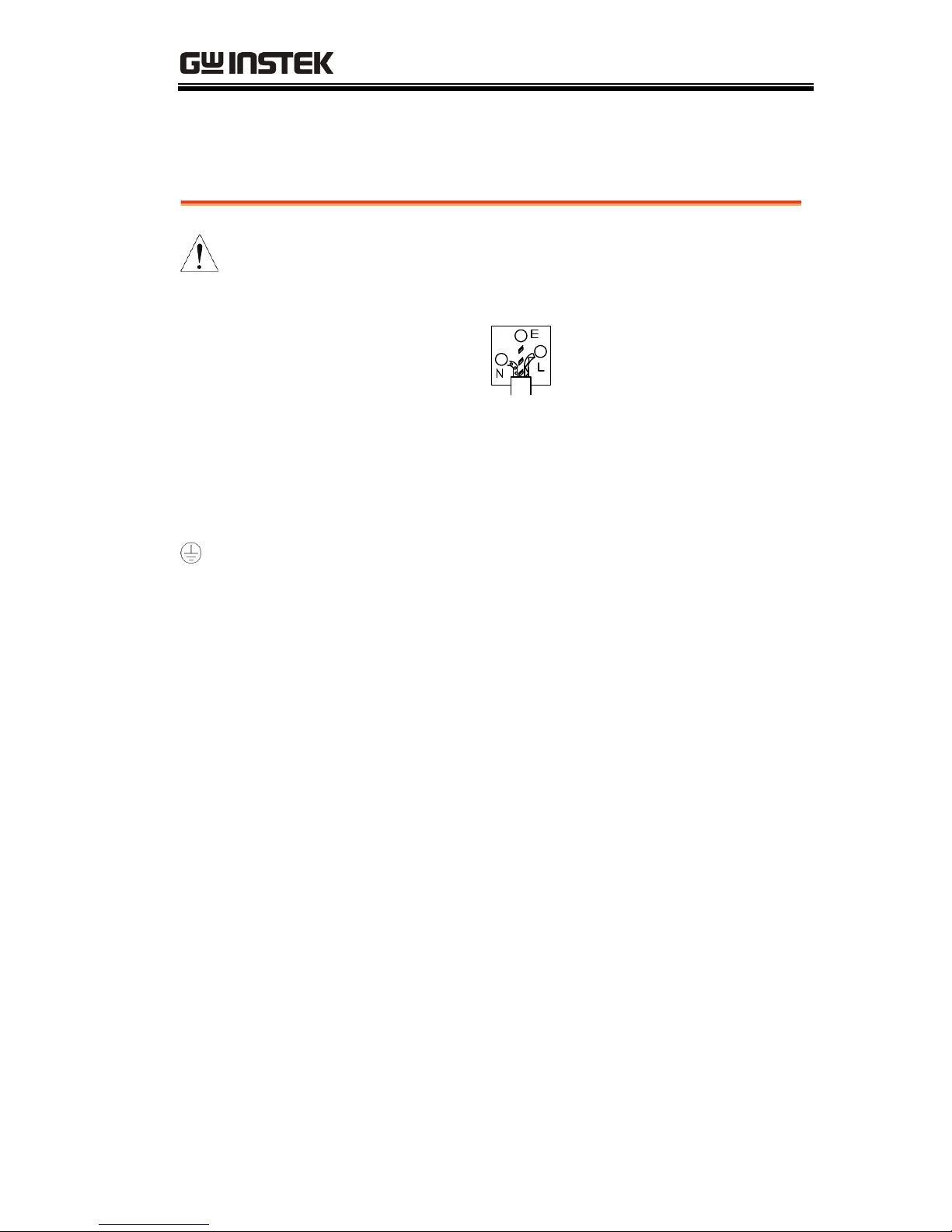
Power cord for the United Kingdom
When using the oscilloscope in the United Kingdom, make sure the
power cord meets the following safety instructions.
NOTE: This lead/appliance must only be wired by competent persons
WARNING: THIS APPLIANCE MUST BE EARTHED
IMPORTANT: The wires in this lead are coloured in accordance with the
following code:
Green/ Yellow: Earth
Blue: Neutral
Brown: Live (Phase)
As the colours of the wires in main leads may not correspond with
the coloured marking identified in your plug/appliance, proceed
as follows:
The wire which is coloured Green & Yellow must be connected to
the Earth terminal marked with either the letter E, the earth symbol
or coloured Green/Green & Yellow.
The wire which is coloured Blue must be connected to the terminal
which is marked with the letter N or coloured Blue or Black.
The wire which is coloured Brown must be connected to the
terminal marked with the letter L or P or coloured Brown or Red.
If in doubt, consult the instructions provided with the equipment
or contact the supplier.
This cable/appliance should be protected by a suitably rated and
approved HBC mains fuse: refer to the rating information on the
equipment and/or user instructions for details. As a guide, a cable
of 0.75mm
2
should be protected by a 3A or 5A fuse. Larger
conductors would normally require 13A types, depending on the
connection method used.
Any exposed wiring from a cable, plug or connection that is
engaged in a live socket is extremely hazardous. If a cable or plug is
deemed hazardous, turn off the mains power and remove the cable,
any fuses and fuse assemblies. All hazardous wiring must be
immediately destroyed and replaced in accordance to the above
standard.

GDS-3000 Series User Manual
10
GETTING STARTED
11
GETTING STARTED
This chapter describes the GDS-3000 in a nutshell,
including its main features and front / rear panel
introduction. After going through the overview,
follow the Set Up section to properly set up the
oscilloscope for first time use. The Set Up section
also includes a starter on how to use this manual
effectively.
GDS-3000 Series Overview .............................................. 12
Series lineup .......................................................................... 12
Main Features ....................................................................... 13
Accessories ............................................................................ 14
Package Contents ................................................................. 16
Appearance ..................................................................... 17
GDS-3554/3354/3254/3154 Front Panel ....................... 17
GDS-3352/3252/3152 Front Panel .................................. 17
Rear Panel ............................................................................. 23
Display ................................................................................... 25
Set Up ............................................................................. 28
Tilt Stand ............................................................................... 28
Power Up .............................................................................. 29
First Time Use ...................................................................... 30
How to Use This Manual .................................................... 33
GDS-3000 Series User Manual
12
GDS-3000 Series Overview
Series lineup
The GDS-3000 series consists of 6 models, divided into 2-channel
and 4-channel versions.
Model name Frequency
bandwidth
Input channels Real-time
Sampling Rate
GDS-3152 150MHz 2 2.5GSa/s
GDS-3252 250MHz 2 2.5GSa/s
GDS-3352 350MHz 2 5GSa/s
GDS-3154 150MHz 4 5GSa/s
GDS-3254 250MHz 4 5GSa/s
GDS-3354 350MHz 4 5GSa/s
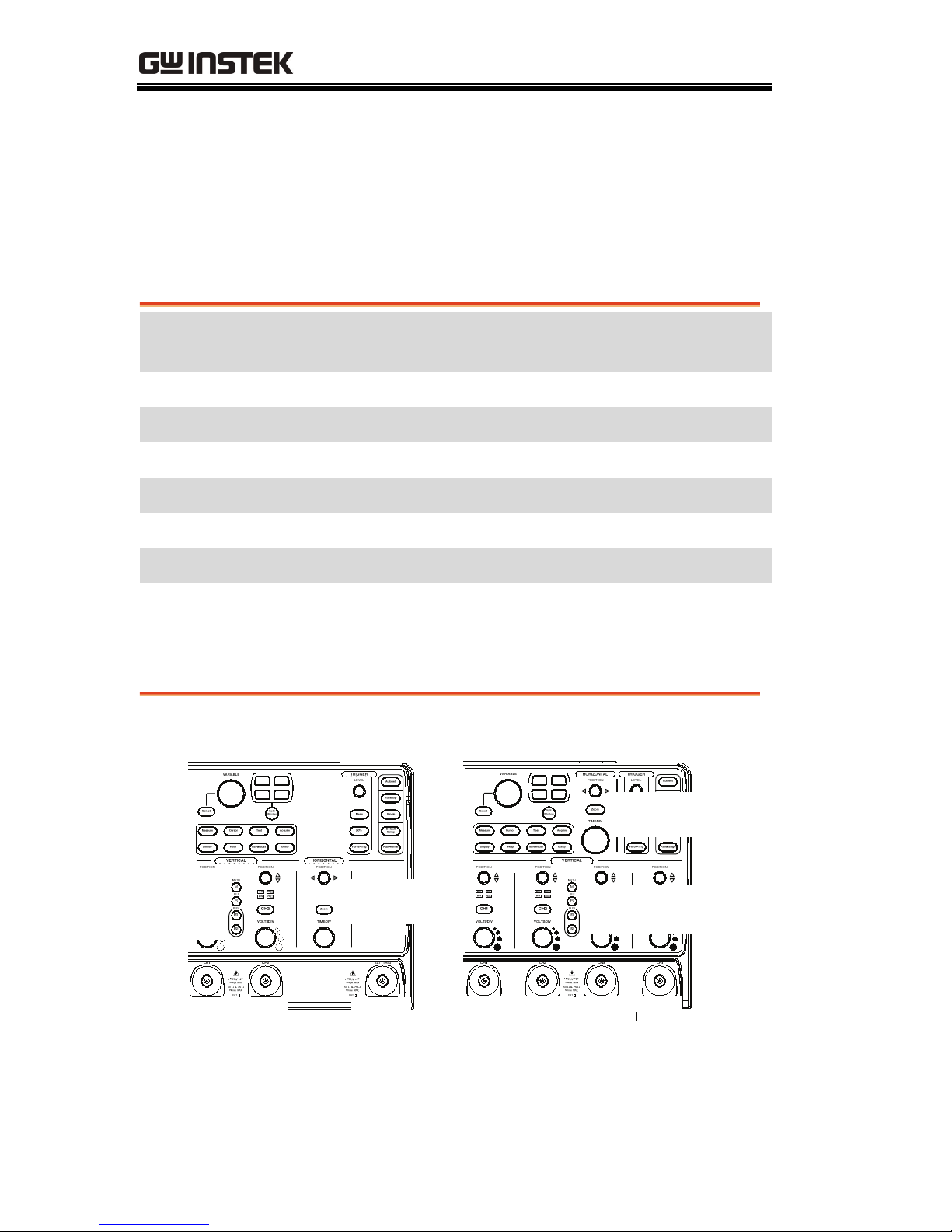
The 2 channel and 4 channel models differ in the position of the
horizontal controls, the math, reference and bus keys as well as the
position of the EXT trigger.
2-Channel model
CH1
input
CH2
input
EXT
trigger
Horizontal
controls
Math,
Reference
Bus keys
4-Channel model
CH1
input
CH2
input
CH3
input
CH4
input
Horizontal
controls
Math, Reference
Bus keys

GETTING STARTED
13
Main Features
Performance
High sampling rate: up to 5GSa/s real-time,
100GSa/s equivalent-time
Deep memory: 25k points record length
Minimum 2ns peak detection
Features
2 and 4 channel models
Bandwidth up to 350 MHz
5GSa/s (200ps resolution) real-time sampling
rate
100GSa/s equivalent sample rate
VPO waveform processing
Large 8’’ 800 x 600 high-resolution TFT LCD
Unique split window function
Flexible application modules
Three standard input impedances
(50Ω/75Ω/1MΩ)
Optional power measurement functions are
available for fast analysis of power quality tests
Optional analysis software for I
2
C, SPI and
UART serial signal triggering and decoding
2 and 4 channel models available up to 350 MHz
Large 8” color TFT LCD, supporting a large 8 x
10 graticule
On-screen Help
64 MB internal flash memory.
Freewave remote control software (free
download)

GDS-3000 Series User Manual
14
Interface
USB host port: front and rear panel, for storage
devices
USB slave port(Optional GPIB to USB), RS-232C
port: for remote control
Calibration output
Go-No Go output
External trigger input
Ethernet port
Accessories
Standard
Accessories
Part number Description
82DS-33040M01 User manual
N/A region dependent Power cord
Options Option Number Description
Opt. 1 GPIB Interface
Optional
Accessories
Part number Description
GTC-001
Instrument cart, 450(W)x430(D)mm
(120V input Socket)
GTC-002
Instrument cart, 330(W)x430(D)mm
(120V input Socket)
GTL-110
test lead, BNC to BNC heads
GTL-232
RS-232C cable, 9-pin Female to 9-pin
female, Null modem for computer
GTL-242
USB cable, USB2.0A-B type cable 4P
GUG-001
USB to GPIB converter
GDP-025
25MHz high voltage differential
probe

GETTING STARTED
15
GDP-050
50MHz high voltage differential
probe
GDP-100
100MHz high voltage differential
probe
GCP-530
50MHz/ 30A current probe
GCP-1030
100MHz/ 30A current probe
GCP-206P
Power supply for current probe (2
input channel)
GCP-425P
Power supply for current probe (4
input channel)
GTP-151R
Passive probe; 150 MHz,10X with
readout
GTP-251R
Passive probe; 250 MHz,10X with
readout
GTP-351R
Passive probe; 350 MHz,10X with
readout
Driver Name Description
dso_cdc.inf USB driver

GDS-3000 Series User Manual
16
Package Contents
Check the contents before using the GDS-3000.
Opening the box
Contents
Main unit
Probe set
GTP-151R for GDS-3152 / GDS-3154
GTP-251R for GDS-3252 / GDS-3254
GTP-351R for GDS-3352 / GDS-3354
Power cord
User manual (this document)
Note
For detailed probe specifications, see page205.
The programming manual, PC software, and
USB driver are downloadable from the
GWInstek website. Visit www.gwinstek.com, in
the oscilloscope section.
GETTING STARTED
17
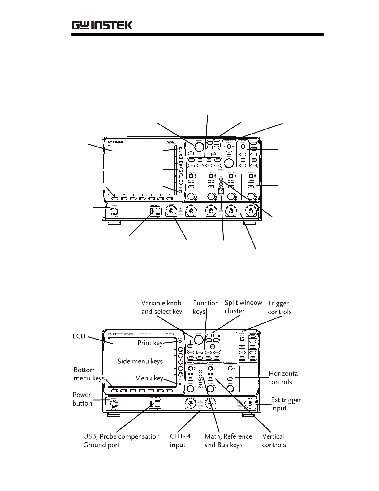
Appearance
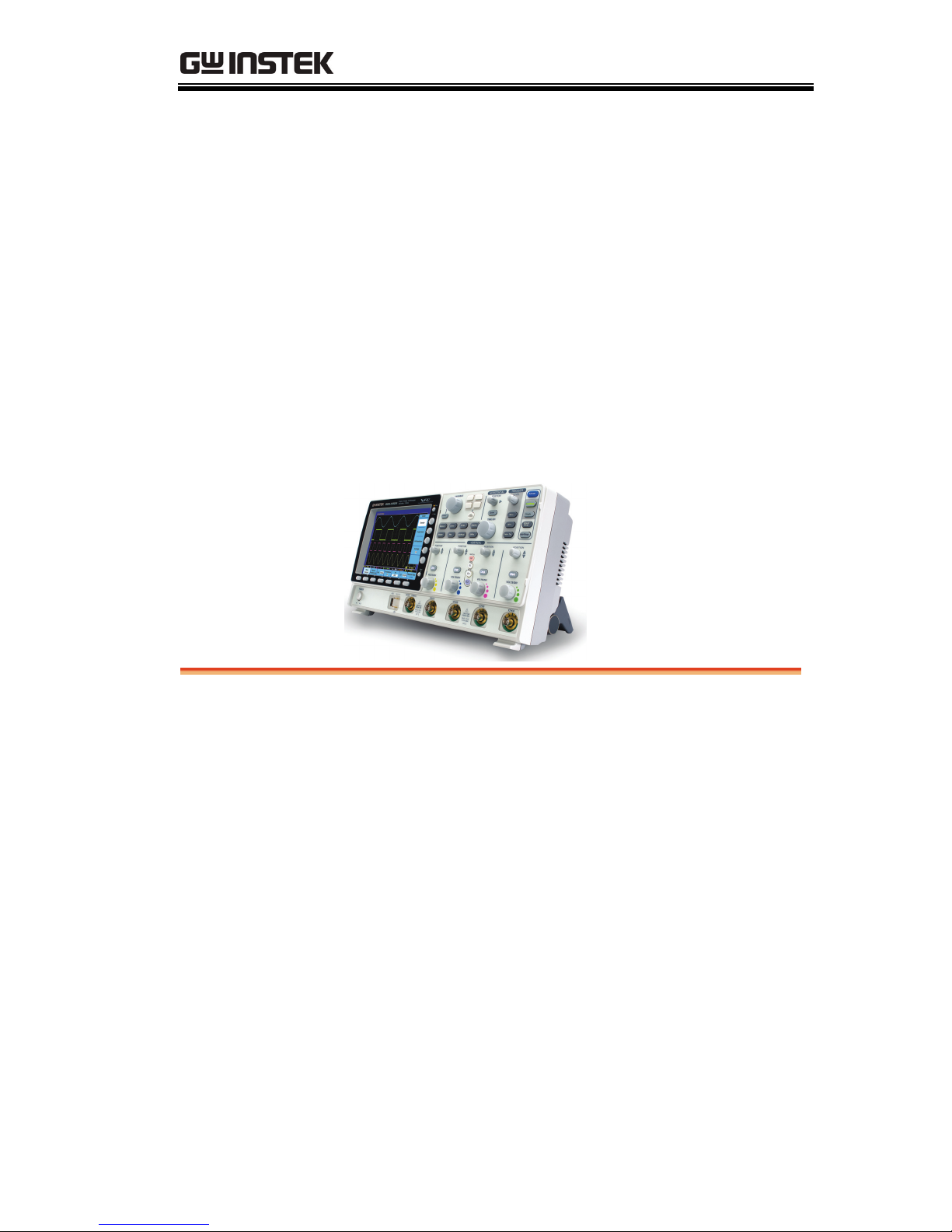
GDS-3554/3354/3254/3154 Front Panel
GDS-3354
LCD
Print key
Variable knob
and select key
Split window
cluster
Horizontal
controls
Trigger
controls
CH1~4
input
Vertical
controls
Math and
Reference
keys
Function
keys
Ext trigger
input
USB
Probe compensation,
Ground port
Power
button
Menu key
Bus keys
Bottom
menu keys
Side menu keys
GDS-3352/3252/3152 Front Panel
GDS-3000 Series User Manual
18
LCD display
8” SVGA TFT color LCD. 800 x 600 resolution,
wide angle view display.
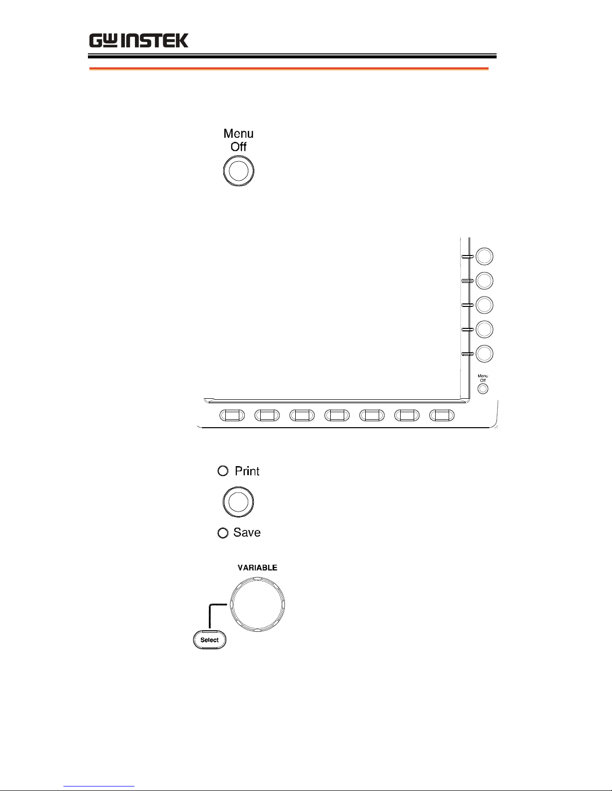
Menu Key
Use the Menu Off key to
hide/show the onscreen menu
system.
Side Menu keys
The Side menu and Bottom menu keys are used to
make selections from the soft-menus on the LCD
user interface.
To choose menu items, use the 7 Bottom
menu keys located on the bottom of the
display panel.
To select a variable or option from a menu,
use the Side menu keys on the side of the
panel. See page 33 for details.
Bottom Menu
keys
Print key
The print key is a quick save or
quick print key, depending on its
configuration. For more
information see pages 156(save) or
178(print).
Variable knob and
Select key
The Variable knob is used to
increase/decrease values or to
move between parameters.
The select key is used to make
selections.
GETTING STARTED
19
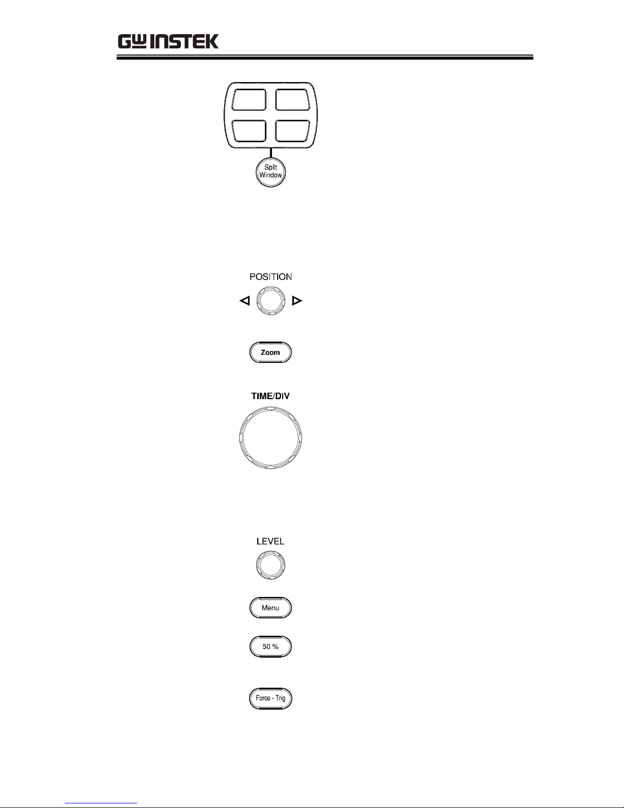
Split Window
Cluster
Use the Split Window key to cycle
between single and split screen
mode. To separate each channel
into a split window, use one of the
four windowed keys. For more
details on windowing see page 67.
Horizontal
Controls
The horizontal controls are used to change the
position of the cursor, set the time base settings,
and to zoom into the waveforms.
Horizontal
Position
The Position knob is used to
position the waveforms vertically
on the display screen.
Zoom
Press Zoom in combination with
the horizontal POSITION knob.
TIME/DIV
The Time/Div knob is used to
change the horizontal scale.
Trigger controls
The trigger controls are used to control the trigger
level and options.
Level Knob
Used to set the trigger level.
Trigger Menu key
Used to bring up the trigger menu.
50% key
Sets the trigger level to the half
way point (50%).
Force - Trig
Press to force an immediate trigger
of the waveform.
GDS-3000 Series User Manual
20
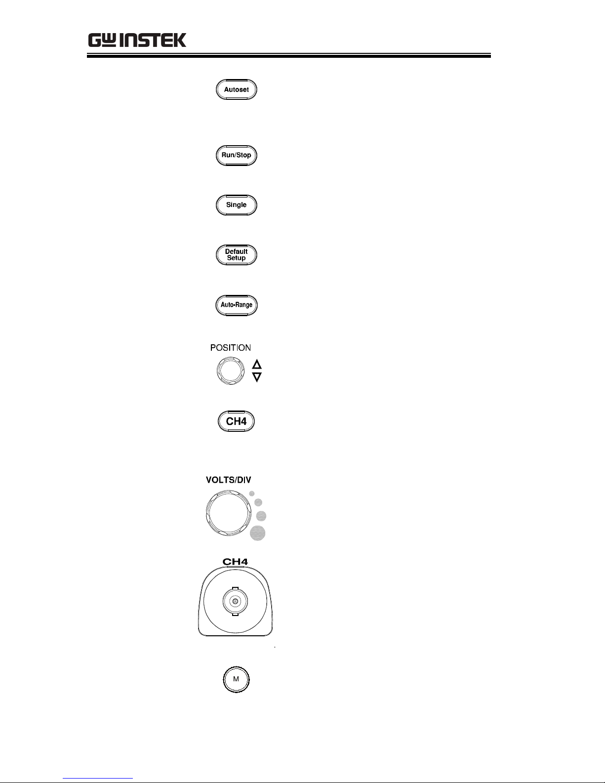
Autoset
Press the Autoset key to
automatically set the trigger,
horizontal scale and vertical scale.
Run/Stop key
Press to Freeze (Stop) or continue
(Run) signal acquisition (page62).
Single
Sets the acquisition mode to single
triggering mode.
Default Setup
Resets the oscilloscope to default
settings.
Auto-Range
Sets the oscilloscope range
automatically.
Vertical
POSITION
Sets the vertical position of the
waveform.
Channel Menu
Key
Press the CH1~4 key to set the
coupling and vertical scale of the
corresponding channel.
VOLTS/DIV Knob
Sets the vertical scale.
Input Terminals
Accepts input signals. Input
impedance, selectable: 50Ω, 75Ω,
1MΩ.
Math key
Use the math key to set and
configure math functions.
GETTING STARTED
21
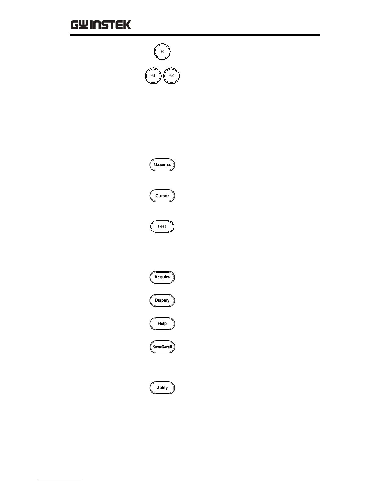
Reference key
Press the Reference key to set or
remove reference waveforms.
BUS keys
The Serial bus decode keys are
used for UART, I
2
C and SPI serial
bus interface decoding. The serial
bus decode function is an optional
extra. See page 95 for details.
Function Keys
The Function Keys are used to enter and configure
different functions on the GDS-3000.
Measure
Configures and runs automatic
measurements.
Cursor
Configures and runs cursor
measurements.
Te st
Configures and runs applications
as well as optional functions such
as the Power Analysis
measurement software.
Acquire
Configures the Acquisition mode.
Display
Configures the display settings.
Help
Shows the Help menu.
Save/Recall
Used to save and recall
waveforms, images and panel
settings.
Utility
Configures the print key, display
time, language and calibration.
GDS-3000 Series User Manual
22
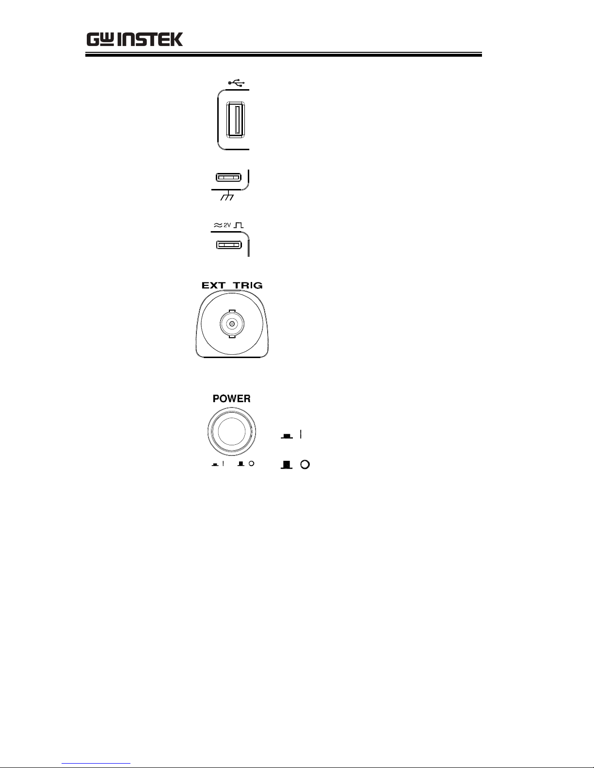
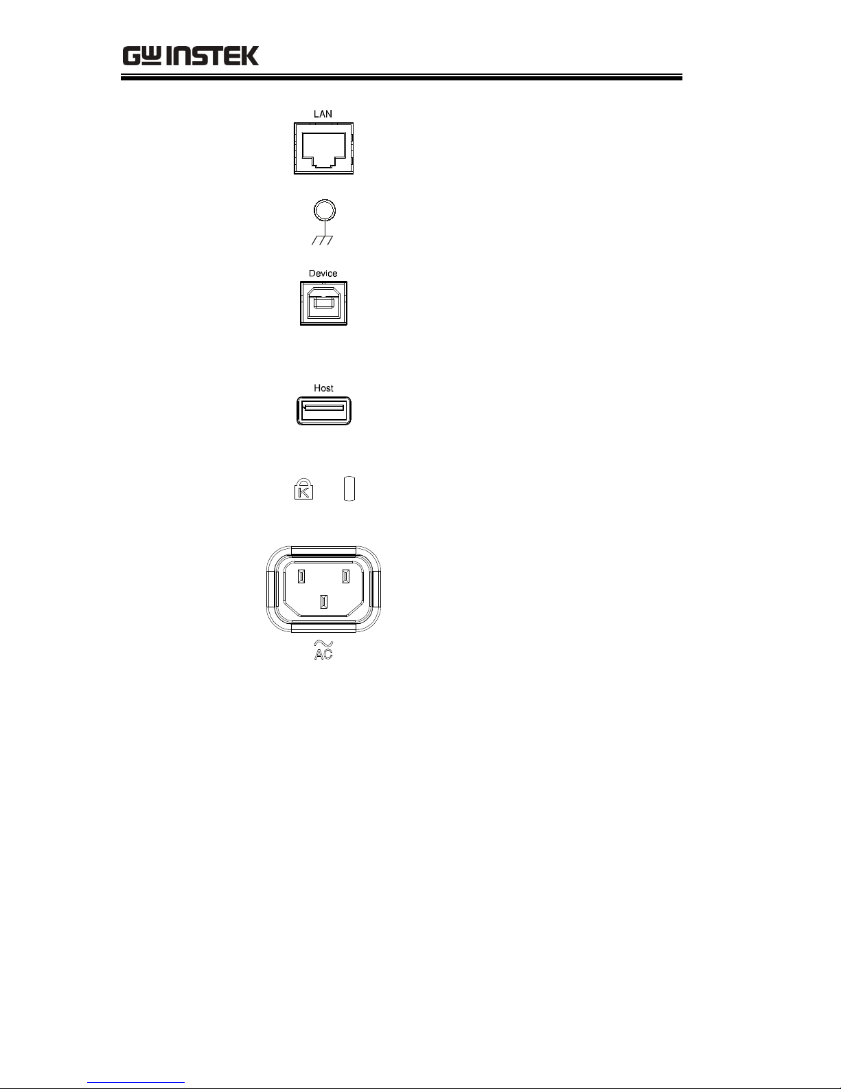
USB host port
TypeA, 1.1/2.0 compatible. Used
for data transfer.
Ground terminal
Accepts the DUT ground lead for
common ground.
Probe
compensation
output
Outputs 2Vp-p, square wave
signal for probe compensation
(page 193).
External trigger
input
Accepts external trigger signals
(page 126).
Input impedance: 1MΩ±3%,
Voltage input: ±15V(peak), EXT
trigger capacitance:~15pF.
Power Switch
Used to turn the power on/off.
: ON
: OFF
GETTING STARTED
23
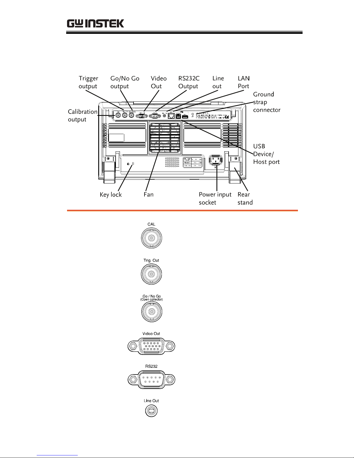
Rear Panel
Calibration
output
Outputs the signal for vertical scale
accuracy calibration (page 191).
Trigger output
Outputs the trigger timing.
Go-No Go output
Outputs Go-No Go test results
(page 88) as 10us pulse signal.
Video Out
Outputs SVGA resolution to an
external display.
RS232
RS232 remote control.
Line Out
Audio line out.
GDS-3000 Series User Manual
24
LAN port
Ethernet port.
Ground strap
connector
For use with a grounding strap.
USB Device Port
The USB device port is used for
remote control and for the
Freewave remote control software.
USB 1.1/2.0 high speed compatible.
USB Host
The USB host port supports USB
flash drives for external memory.
USB 1.1/2.0 high speed compatible.
Security Slot
Kensington security slot
compatible.
Power Input
Socket
Power cord socket accepts AC
mains, 100 ~ 240V, 50/60Hz.
For power up sequence, see page
29.
GETTING STARTED
25
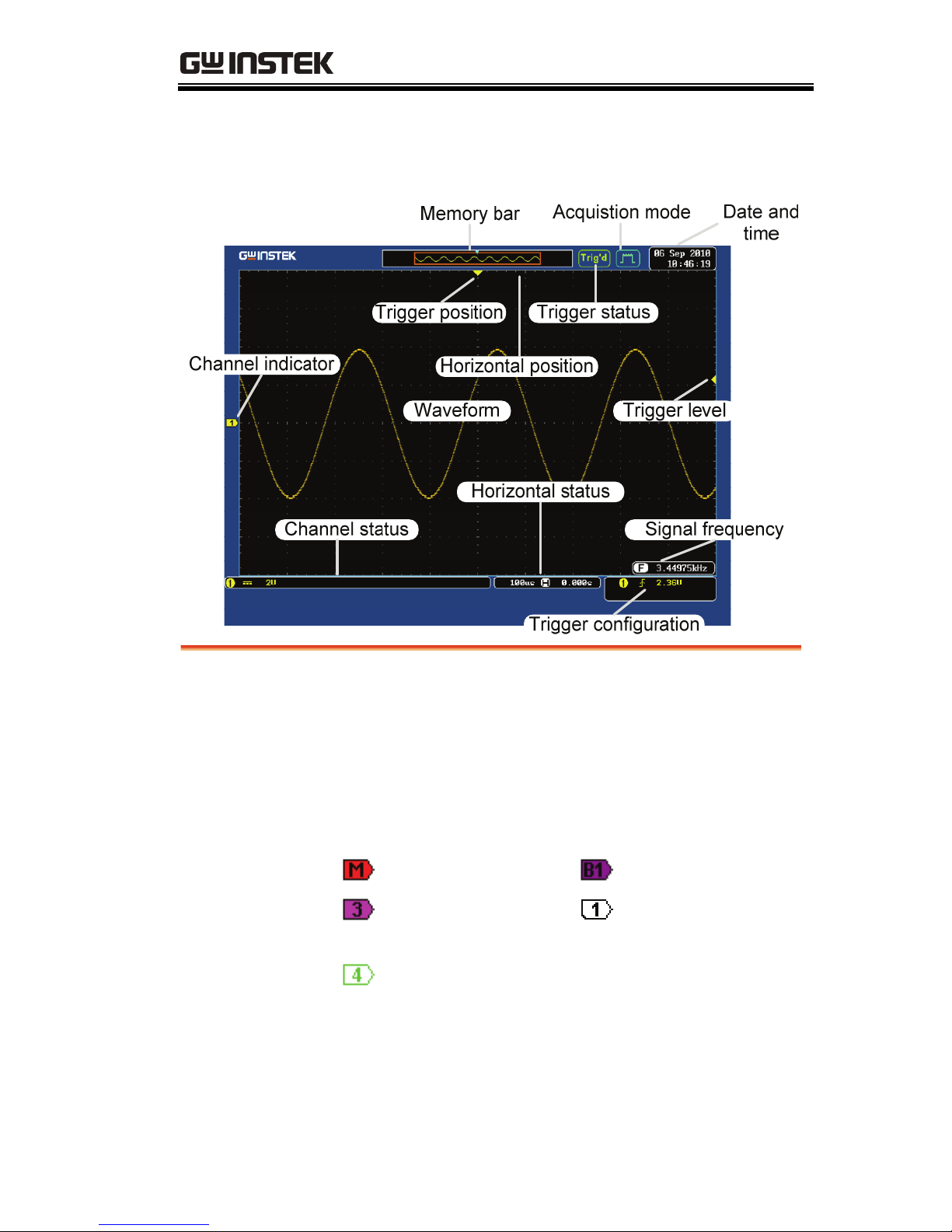
Display
Waveforms
Shows input signal waveforms.
Channel 1: Yellow Channel 2: Blue
Channel 3: Pink Channel 4: Green
Channel Indicator
The channel indicator shows the zero volt level of
the signal waveform for each activated channel.
The active channel is shown with a solid color.
Math Bus (B1)
Active channel
(CH3)
Reference waveform
(Ref1)
Activated channel
(CH4)
Trigger position
Shows the position of the trigger.
Horizontal
position
Shows the horizontal position.
GDS-3000 Series User Manual
26
Date and Time
Current date and time (page 145).
Memory bar
The ratio and the position of the
displayed waveform compared
with the internal memory (page
114).
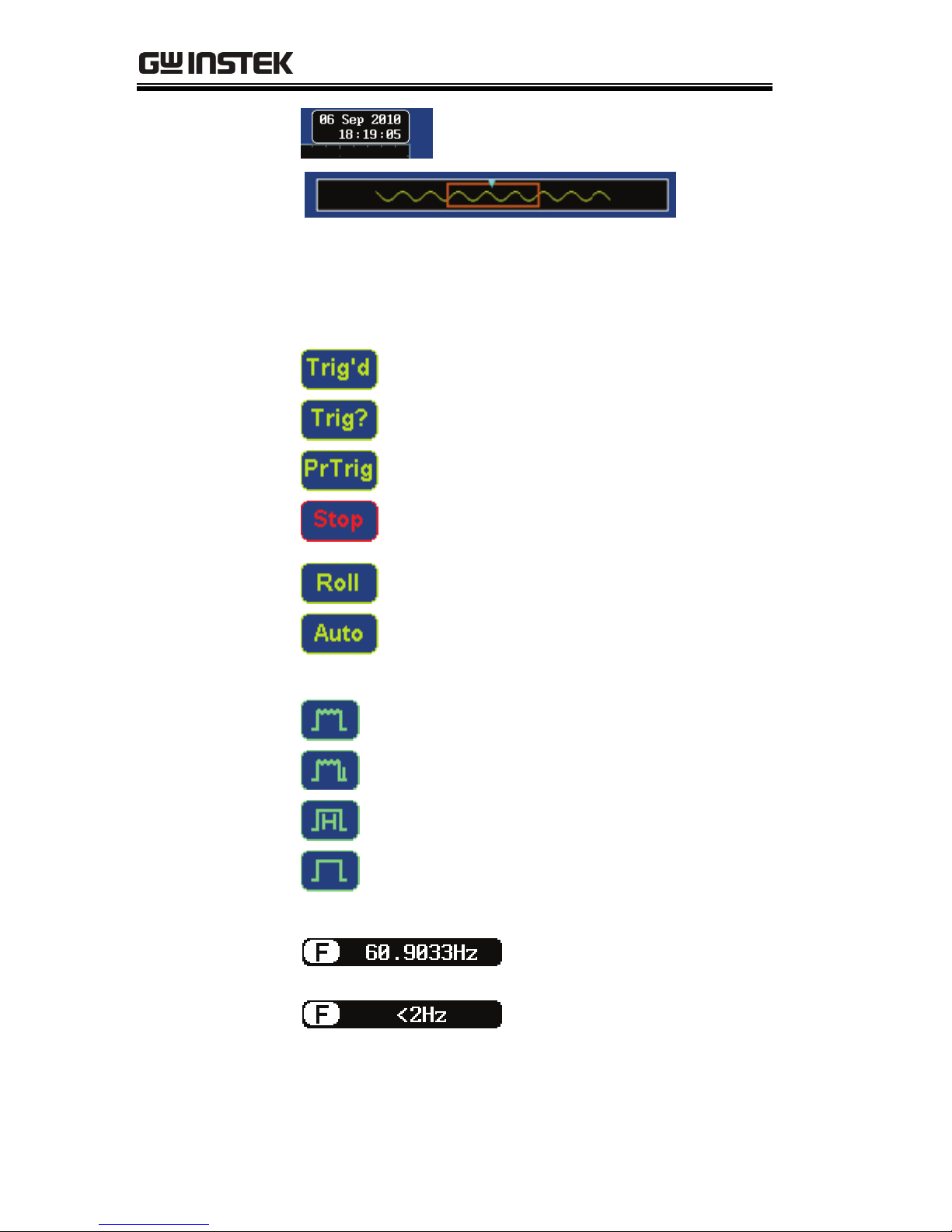
Trigger status
Triggered.
Not triggered, display not updated.
Indicates the pre-trigger is active.
Trigger stopped. Also appears in
Run/Stop (page62).
Roll mode.
Autoset mode.
For trigger details, see page 126.
Acquisition mode
Normal mode
Peak detect mode
Hi Resolution
Average mode
For acquisition details, see page 101.
Input signal
frequency
Shows the input signal
frequency.
Indicates the frequency is
less than 2Hz (lower
frequency limit).
GETTING STARTED
27
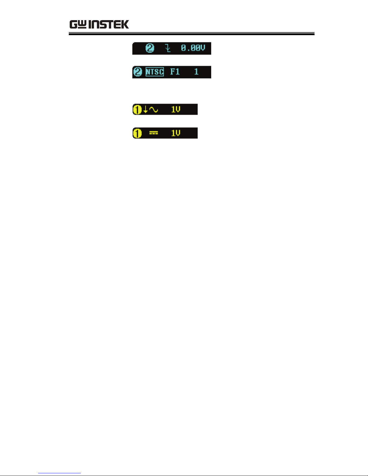
Trigger
configuration
Trigger source, slope,
voltage.
Trigger source, trigger
(video), field, line.
For trigger details, see page 126.
Channel status
Channel 1, inverted, AC
coupling, 1V/Div
Channel 1, GND coupling,
1V/Div
For channel details, see page 119.

GDS-3000 Series User Manual
28
Set Up
Tilt Stand
Upright
Turn the legs under the casing as shown below to
have the instrument sit upright.
Tilt
To tilt, tilt the legs back behind the casing, as
shown below.
GETTING STARTED
29
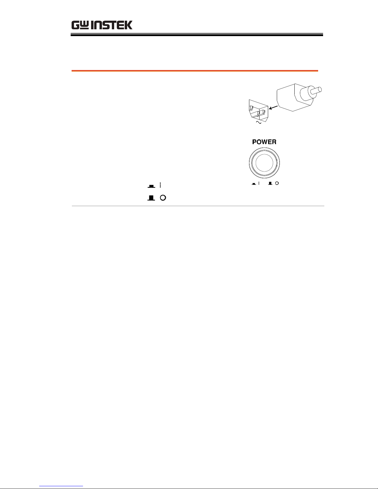
Power Up
Step
1. Connect the power cord to
the rear panel socket.
A
C
2. Press the POWER key. The
display becomes active in 6
~ 8 seconds.
: ON
: OFF
Note
The GDS-3000 recovers the state right before the
power is turned OFF. The default settings can be
recovered by pressing the Default key on the front
panel. For details, see page 161.
GDS-3000 Series User Manual
30
First Time Use
Background
This section describes how to connect a signal,
adjust the scale, and compensate the probe. Before
operating the GDS-3000 in a new environment,
run these steps to make sure the instrument
performs at its full potential.
1. Power On
Follow the procedures on the previous page.
2. Set the date
and time
Set the date and time.
Page 145
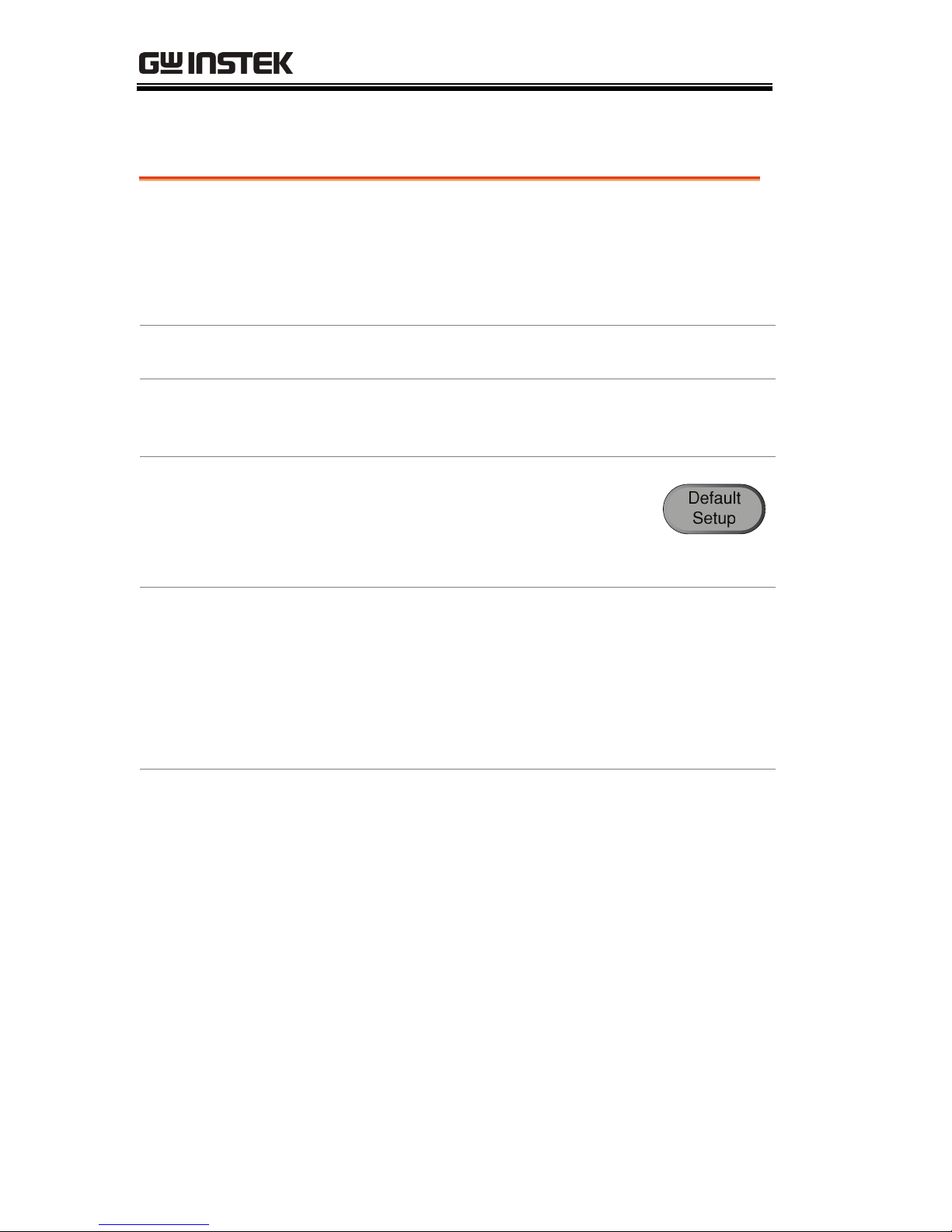
3. Reset system
Reset the system by recalling the
factory settings. Press the Default
Setup key on the front panel. For
details, see page 161.
4. Install optional
software
The optional software packages
(Power Analysis, Serial Bus Decode)
can be activated. If the optional
software has not been purchased, a
time trial demonstration can be
activated.
Page 195
5. Connect probe
Connect the probe to the Channel1 input terminal
and probe compensation signal output (2Vp-p,
1kHz square wave).
Set the probe attenuation to x10 if the probe has
adjustable attenuation.
 Loading...