

Page 1
Instructions
PNEG-911
1004 East Illinois Street • Assumption, IL 62510 • 1-217-226-4421
Manual Roof Vent Instruction Sheet
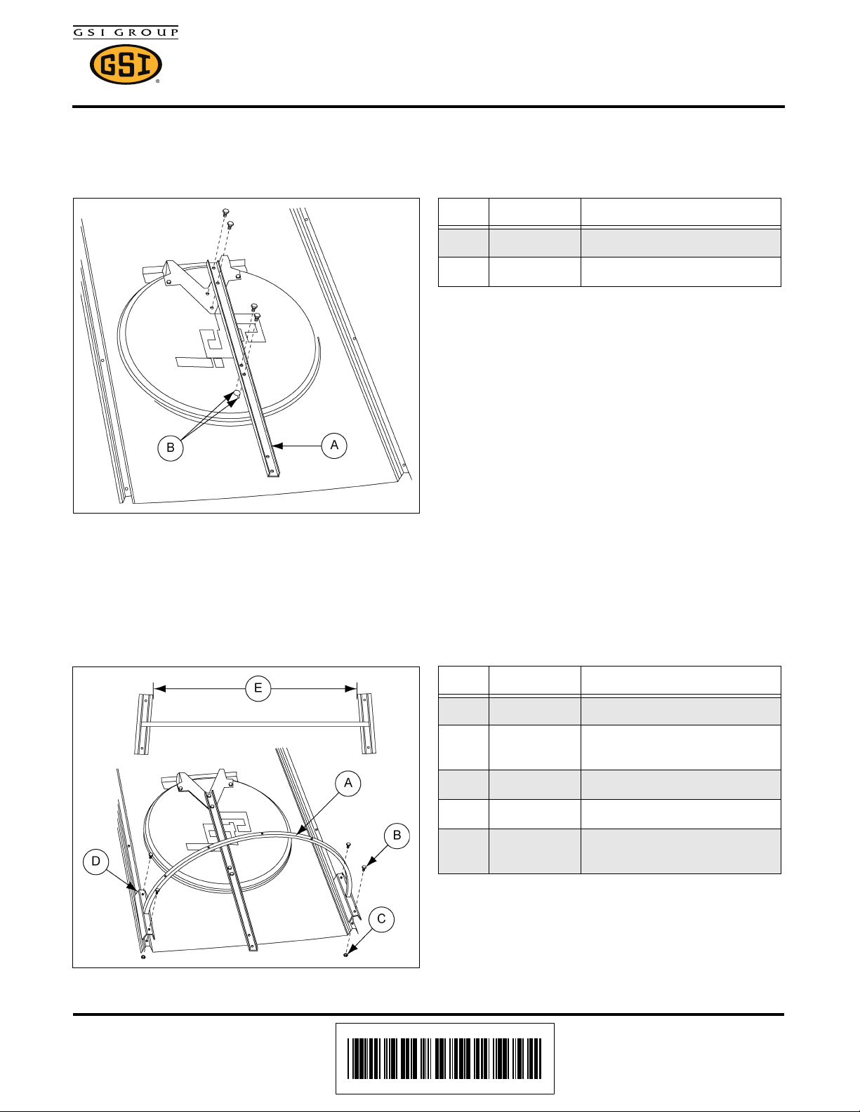
STEP 1: Placement of manual roof vent lid bracket assemble manway as denoted in the roof manual
(PNEG-030).
Attach lid bracket with 5/16" x 3/4" bolts (S-275) and 5/16"-18 nuts (S-396). (See Figure 1.)
Ref # Part # Description
A MIS-6887 Manual Vent Lid Bracket
B Field Drill Holes to 3/8" Diameter
Figure 1
STEP 2: Placement of manual roof vent hoop.
Attach brackets with 5/16"-18 x 1-1/4" bolts (S-277) (B) and 5/16"-18 nuts (S-396) (C).
Secure one bracket to rib, then fasten other side. bottom hole in bracket bolts to bottom hole in
roof panel rib. (See Figure 2.)
Ref # Part # Description
A MIS-6886 Manual Vent Hoop
BS-277
C S-396 Hex Nut 5/16"-18 YDP Grade 2
D Field Drill 3/8" Hole in Roof Rib
E
Bolt, HHBIN 5/16"-18 x 1-1/4"
YDP Grade 5
Narrow end of brackets are to be
positioned towards manway.
Figure 2
Date: 10-10-13 PNEG-911
Printed in the U.S.A.
Copyright © 2013 by GSI Group
www.gsiag.com
Page 1 of 4
CN-308842
Page 2
Manual Roof Vent Instruction Sheet
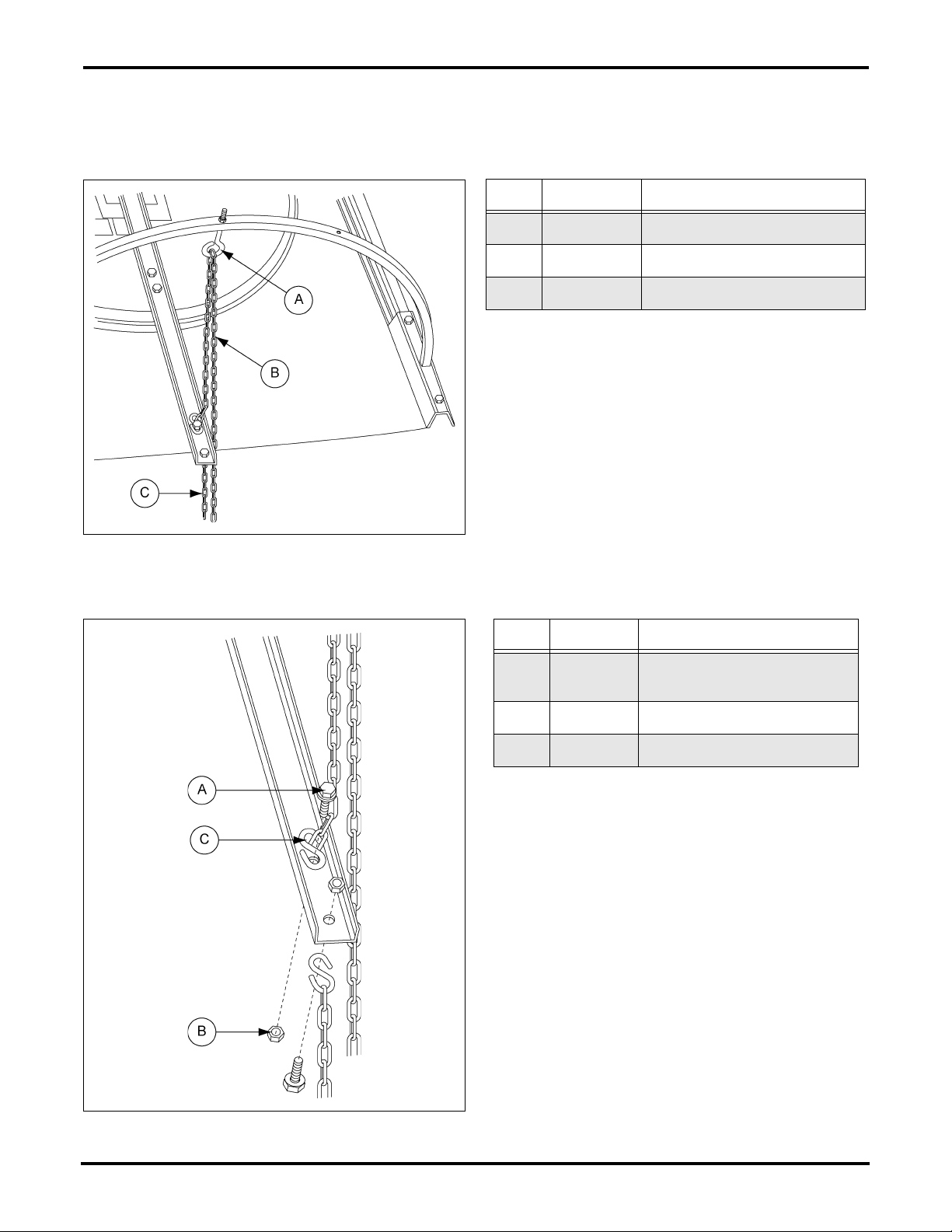
Chain Route Detail
STEP 3: Attach eye bolt to the hoop and run the lifting chain through. Crimp S-hook to end of chain and
attach to the lifting bracket with 5/16" x 1-1/4" bin bolt. (See Figure 3.)
Ref # Part # Description
A S-7062 Eye Bolt 3/8"-16 x 2-1/4" ZN
B “Open” Chain
C “Close” Chain
Figure 3
STEP 4: Crimp the S-hooks (C) to attach them to the chain and bolt. (See Figure 4.)
Ref # Part # Description
A S-277 Bolt, HHBIN 5/16"-18 x 1-1/4"
YDP Grade 5
B S-396 Hex Nut 5/16"-18 YDP Grade 2
C S-4692 S-Hook
Figure 4 Chain Attachment Detail
Page 2 of 4 PNEG-911
Page 3
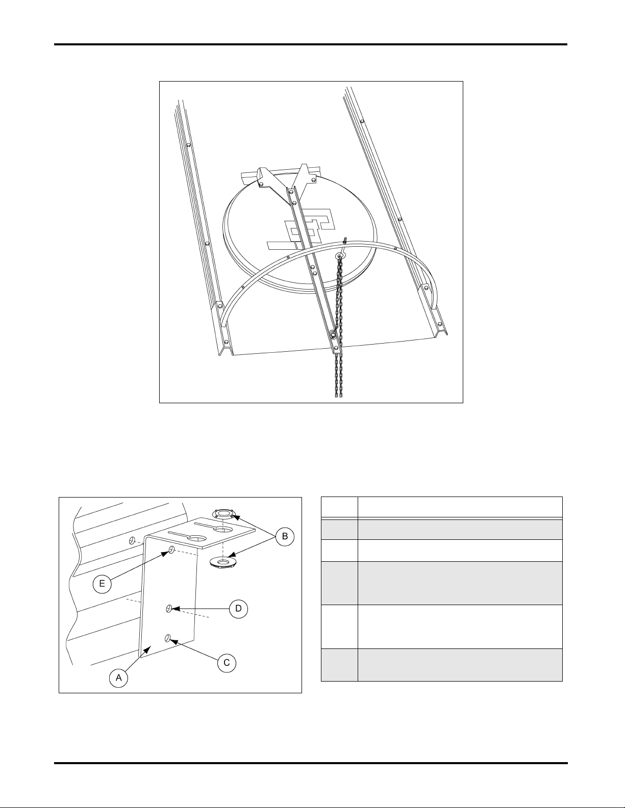
Completed Lid Assembly
Manual Roof Vent Instruction Sheet
Figure 5
Chain Holder Brackets Assembly
Two (2) piece threaded nylon bushing (BLK-11876) (B) place one in each hole. (See Figure 6.)
Ref # Description
A Chain Holder Bracket (MIS-6890)
B Nylon Bushings (BLK-11876)
Hole used with 4" sidewall corrugation
C
(field drill hole in sidewall). Use 5/16" x 3/4"
bolt and 5/16" nut to fasten.
Hole used with 2.66" sidewall corrugation
D
(field drill hole in sidewall). Use 5/16" x 3/4"
bolt and 5/16" nut to fasten.
Top hole connects to pre-existing sidewall
E
horizontal seam hole.
Figure 6
PNEG-911 Page 3 of 4
Page 4

Manual Roof Vent Instruction Sheet
Chain Holder Brackets Assembly (Continued)
Chain holder bracket will contain both the “open” and “closed” chains.
Place the brackets at the bottom horizontal seam of the top ring. Then every 3 rings down.
Quantity of brackets used will depend on height of tank. (See Figure 7.)
Figure 7
Bottom chain holder bracket is to be installed without the two (2) piece nylon bushings. Place bracket
about eye level. You will need to field drill 4.00" corrugated sidewall tanks.
Slots in brackets should be used to secure chain in open or shut position.
Place handle on “open” chain below bottom chain holder bracket.
Place split ring (S-4318) (B) under handle. (See Figure 8.)
Ref # Part # Description
A CRP-5810-BS Plastic Handle
B S-4318 Split Ring
Figure 8
Page 4 of 4 PNEG-911
 Loading...