

Page 1

PNEG-4042
40 Series 42' and 48' Diameter Bins
Construction Manual
PNEG-4042
Date: 06-14-13
Page 2

All information, illustrations, photos, and specifications in this manual are based on the lates t
information available at the time of publication. The right is reserved to make changes at any
time without notice.
2 PNEG-4042 40 Series 42' and 48' Diameter Bins
Page 3

Table of Contents
Contents
Chapter 1 Safety ..................................................................................................................................................... 5
Safety Guidelines .................................................................................................................................. 5
General Safety Statement ..................................................................................................................... 6
Safety Instructions ..................... ... .... .......................................... ... ........................................................ 7
Safety Sign-Off Sheet ........................................................................................................................... 9
Chapter 2 Decals .................................................................................................................................................. 10
Roof Damage Warning and Disclaimer ............................................................................................... 10
Overfill Warning ...................... ... ... .......................................... .... ................................................ ... ...... 13
Chapter 3 General Overview ............................................................................................................................... 14
General Information ............................................................................................................................ 14
Anchor Bolt Charts .............................................................................................................................. 14
Tools Required for Construction ......................... ... ... .... ... ... ... .......................................... ... .... ...... ... ... 19
Guidelines for Proper Storage of Grain Bin Materials Prior to Construction .............................. ... ...... 19
Guidelines for Construction Procedures and Lifting Jack Usage ........................................................ 20
Guidelines for Placement of the Decal Sidewall Sheet ....................................................................... 21
Chapter 4 Bolt and Nut Usage ............................................................................................................................ 22
Hardware Requirements for Sidewalls and Stiffeners ......................................................................... 22
Bolt Identification ................................................................................................................. .... ... ... ... ... 25
Color Chart for Bin Hardware Bucket Lids .......................................................................................... 30
Chapter 5 Assembling Sidewall Sheets ............................................................................................................. 31
Color Codes for Sidewall Gauge Identification .......... ................. ................ ................ ................ ......... 31
Caulking Detail for Standard (Non-Laminated) Sheets ....................................................................... 32
Caulking Detail for Laminated Quad Pattern Sheets .......................................................................... 34
Chapter 6 Stiffeners ............................................................................................................................................. 37
Stiffener Part Number Description ...................................................................................................... 37
Color Codes for Stiffener Gauge Identification .... ................ ................ ................ ................ ................ 37
Standard Stiffeners ............................................................................................................................. 38
Top Stiffeners ...................................................................................................................................... 39
Stiffeners Splice .................................................................................................................................. 40
Base Stiffeners .................................................................................................................................... 41
Base Boots .......................................................................................................................................... 42
Close-Punch Connection for a 1 Ring Top Stiffener (16 Gauge) and a 2 Ring Stiffener (16 Gauge) . 43
2 Ring Top Stiffener to a 2 Ring Stiffener (15-16 Gauge) Connection ................................................ 44
Close-Punch Connection for a 2 Ring Top Stiffener to a 2 Ring Stiffener (16 Gauge) ....................... 45
2 Ring Stiffener (15-16 Gauge) to a 2 Ring Stiffener (15-16 Gauge) Connection ............................... 46
Close-Punch Connection for a 2 Ring Stiffener (16 Gauge) to a 2 Ring Stiffener (16 Gauge) ........... 47
2 Ring Stiffener (0-14 Gauge) to a 2 Ring Stiffener (0-14 Gauge) Connection ................................... 48
Close-Punch Connection for a 2 Ring Stiffener (0-14 Gauge) to a 2 Ring Stiffener (0-14 Gauge) ..... 49
2 Ring Stiffener (0-14 Gauge) to a Close-Punch Base Stiffener (2-8 Gauge) Connection ................. 50
Close-Punch Connection for a 2 Ring Stiffener (0-14 Gauge) to a Base Stiffener (2-8 Gauge) ......... 51
2 Ring Stiffener (0-14 Gauge) to a Base Stiffener (10-16 Gauge) Connection ....... ... ... ... ... .... ... ... ... ... 52
2 Ring Stiffener (2-14 Gauge) to a Base Stiffener (10-16 Gauge) Connection ....... ... ... ... ... .... ... ... ... ... 53
2 Ring Stiffener (15-16 Gauge) to a Base Stiffener (10-16 Gauge) Connection ................................. 54
Close-Punch Connection for a 2 Ring Stiffener (16 Gauge) to a Base Stiffener (10-16 Gauge) ........ 55
Close-Punch 2 Ring Stiffener (2-14 Gauge) to a Laminated Stiffener (2 Gauge)
with an Insert (10-14 Gauge) .............................................................................................................. 56
Close-Punch Laminated Stiffeners (2 Gauge) with Inserts (10-14 Gauge) ......................................... 57
Close-Punch Laminated Stiffener (2 Gauge) with an Insert (10-14 Gauge)
to a Laminated Base Stiffener (2-5 Gauge) with a Base Insert (2-14 Gauge) .................................... 58
Base Stiffener (10-16 Gauge) to a Base Boot Connection ................................................................. 59
PNEG-4042 40 Series 42' and 48' Diameter Bins 3
Page 4

Table of Contents
Close-Punch Connection for a Base Stiffener (10-16 Gauge) to a Base Boot .................................... 60
Close-Punch Connection for a Base Stiffener (2+2 Gauge - 8 Gauge) to a Base Boot ...................... 61
Close-Punch Laminated Base Stiffener (2 Gauge) with Insert (2+14 to 2+10 Gauge) to a Base Boot 62
Close-Punch Standard Stiffener to a 12 Bolt Pattern Laminated Stiffener with Insert ........................ 63
12 Bolt Pattern Close-Punch Laminated Stiffeners with Insert ........................................................... 64
Close-Punch 12 Bolt Pattern Laminated Stiffener to Laminated Base Stiffener
with an Inserts to a Base Boot ............................................................................................................ 65
Close-Punch 12 Bolt Pattern Laminated Stiffener to Laminated Base Stiffener
with an Inserts to a Base Boot ............................................................................................................ 66
Chapter 7 Base Angle Installation ...................................................................................................................... 67
Installing the Base Angle ..................................................................................................................... 67
Anchor Bolt Detail ............................................................................................................................... 68
Installing the Base Angle Shims .......................................................................................................... 69
Anchor Bolt Washer Installation .......................................................................................................... 70
Chapter 8 Instructions ......................................................................................................................................... 71
Instructions for Stirring Devices .......................................................................................................... 71
Auto-Vent Assembly and Installation Instructions ............................................................................... 72
Wire Grill Guard Roof Vent Assembly and Installation Instructions .................................................... 75
Chapter 9 Manway Cover Assembly .................................................................................................................. 78
Round Manway Cover ......................................................................................................................... 78
Chapter 10 Center Collar Details ........................................................................................................................ 79
Chapter 11 Roof Assembly ................................................................................................................................. 80
Chapter 12 Support Ring Instructions ............................................................................................................... 82
Ring Instructions ................................................................................................................................ 82
Roof Support Ring Instructions .......................................................................................................... 83
42' and 48' Roof Instructions ............................................................................................................. 86
Chapter 13 Roof Stiffener Location and Detail .................................................................................................. 87
Three (3) Stiffeners per Sidewall Sheet Commercial Stiffener Starting Location -
42' Diameter to 48' Diameter 2.66" Reverse Corrugation Outside Stiffener Only ............................. 87
42' through 48' Standard Roof Stiffener Detail 2.66" Corrugation Outside Stiffener Only ................. 88
Chapter 14 Roof Assembly Instructions ......................................... ................................ ................................... 89
42' and 48' Roof Assembly Instructions ............................................................................................. 89
42' and 48' Roof Truss Assembly ...................................................................................................... 90
42' and 48' Flat Top Instructions ........................................................................................................ 92
Chapter 15 Roof Truss Details ............................................................................................................................ 93
Temperature Cable Support (CRP-5286) (42' and 48' (12.80 m and 14.63 m) Support System) ..... 93
42' and 48' Roof Truss Details ........................................................................................................... 94
42' and 48' Rafter/Splice/Support Intersection Detail ........................................................................ 96
Chapter 16 48' Roof Support System ................................................................................................................. 97
Field Fabricated Temperature Cable Support Attachment ........................... ... ... .... ... ... ... .................. 97
30° Roof Panel Information ............................................................................................................... 97
Chapter 17 Accessories ...................................................................................................................................... 98
Wind Ring Requirements ................................................................................................................... 98
Installing Wind Rings .........................................................................................................
Chapter 18 Warranty .......................................................................................................................................... 103
4 PNEG-4042 40 Series 42' and 48' Diameter Bins
................ 99
Page 5
1. Safety
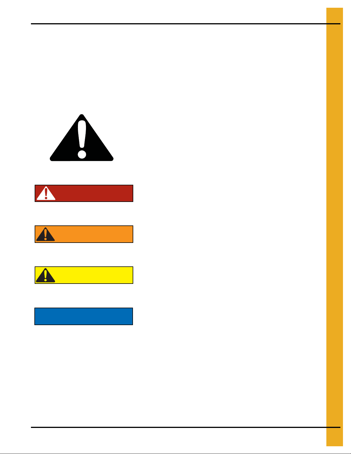
DANGER
WARNING
CAUTION
NOTICE
This is the safety alert symbol. It is used to alert you
to potential personal injury hazards. Obey all safety
messages that follow this symbol to avoid possible
injury or death.
WARNING indicates a hazardous situation which, if not
avoided, could result in death or serious injury.
CAUTION, used with the safety alert symbol, indicates a
hazardous situation which, if not avoided, could result in
minor or moderate injury.
NOTICE is used to address practices not related to
personal injury.
DANGER indicates a hazardous situation which, if not
avoided, will result in death or serious injury.
Safety Guidelines
This manual contains information that is important for you, the owner/operator, to know and understand.
This information relates to protecting personal safety and preventing equipment problems. It is the
responsibility of the owner/operator to inform anyone operating or working in the area of this equipment
of these safety guidelines. To help you recognize this information, we use the symbols that are defined
below. Please read the manual and pay attention to these sections. Failure to read this manual and its
safety instructions is a misuse of the equipment and may lead to serious injury or death.
PNEG-4042 40 Series 42' and 48' Diameter Bins 5
Page 6

1. Safety
This product has sharp edges, which may cause serious injury. To avoid injury, handle
sharp edges with caution and always use proper protective clothing and equipment.
General Safety Statement
Our foremost concern is your safety and the safety of others associated with grain handling equipment.
This manual is to help you understand safe operating procedures and some problems that may be
encountered by the operator and other personnel.
As owner and/or operator, you are responsible to know what requirements, hazards, and precau tions exist
and inform all personnel associated with the equipment or in the area. Safety precautions may be required
from the personnel. Avoid any alterations to the equipment, which may produce a very dangerous
situation, where SERIOUS INJURY or DEATH may occur.
You should consider the location of the bin site relative to power line locations or electrical transmission
equipment. Contact your local power company to review your installation plan or for information
concerning required equipment clearance. Clearance of portable equipment that may be taken to the bin
site should also be reviewed and considered. Any electrical control equipment in contact with the bin
should be properly grounded and installed in accordance with National Electric Code provisions and other
local or national codes.
This product is intended for the use of grain storage only. Any other use is a misuse of the product.
Sidewall bundles or sheets must be stored in a safe manner. The safest method of storing sidewall
bundles is laying horizontally with the arch of the sheet upward, like a dome. Sidewall sheets stored on
edge must be secured so that they cannot fall over and cause injury. Use care when handling and moving
sidewall bundles.
Personnel operating or working around equipment should read this manual. This manual must be
delivered with equipment to its owner. Failure to read this manual and its safety instructions is a
misuse of the equipment.
6 PNEG-4042 40 Series 42' and 48' Diameter Bins
Page 7
1. Safety
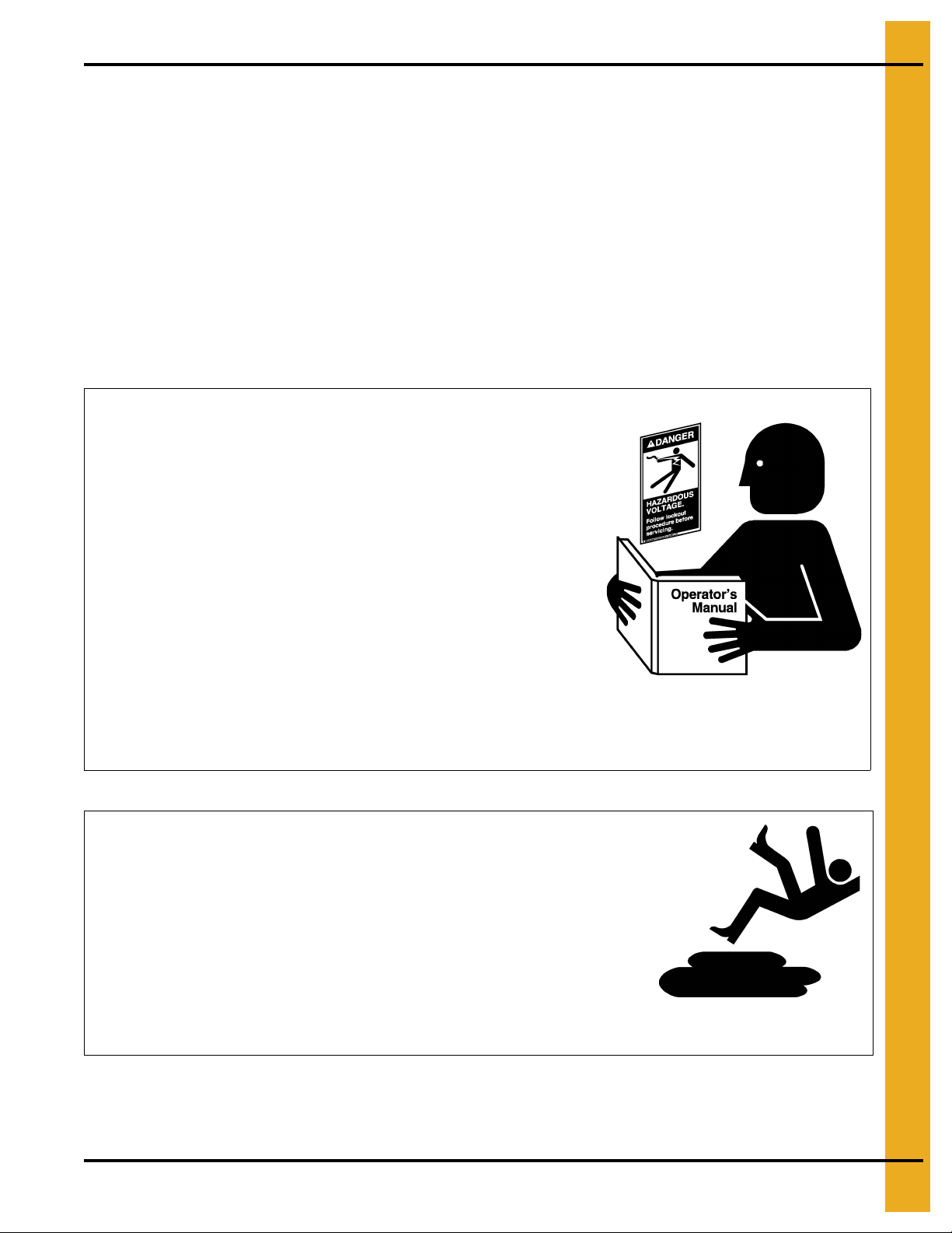
Follow Safety Instructions
Carefully read all safety messages in this manual and
safety signs on your machine. Keep signs in good
condition. Replace missing or damaged safety signs. Be
sure new equipment components and repair parts include
the current safety signs. Replacement safety signs are
available from the manufacturer.
Learn how to operate the machine and how to use controls
properly. Do not let anyone operate without instruction.
Keep your machinery in proper working condition.
Unauthorized modifications to the machine may impair
the function and/or safety and affect machine life.
If you do not understand any part of this manual or need
assistance, contact your dealer.
Read and Understand Manual
Practice Safe Maintenance
Understand service procedures before doing work. Keep area
clean and dry.
Never lubricate, service, or adjust machine while it is in operation.
Keep hands, feet and clothing away from rotating parts.
Keep all parts in good condition and properly installed. Fix
damage immediately . Replace worn or broken p arts. Remove any
built-up grease, oil, and debris.
Maintain Equipment
and Work Area
Safety Instructions
Our foremost concern is your safety and the safety of others associated with this equipment. We want to
keep you as a customer. This manual is to help you understand safe operating procedures and some
problems that may be encountered by the operator and other personnel.
As owner and/or operator, it is your responsibility to know what requirements, hazards, and precautions
exist, and to inform all personnel associated with the equipment or in the area. Safety precautions may be
required from the personnel. Avoid any alterations to the equipment. Such alterations may produce a very
dangerous situation where SERIOUS INJURY or DEATH may occur.
This equipment shall be installed in accordance with the current installation codes and applicable
regulations, which should be carefully followed in all cases. Authorities having jurisdiction should be
consulted before installations are made.
PNEG-4042 40 Series 42' and 48' Diameter Bins 7
Page 8
1. Safety
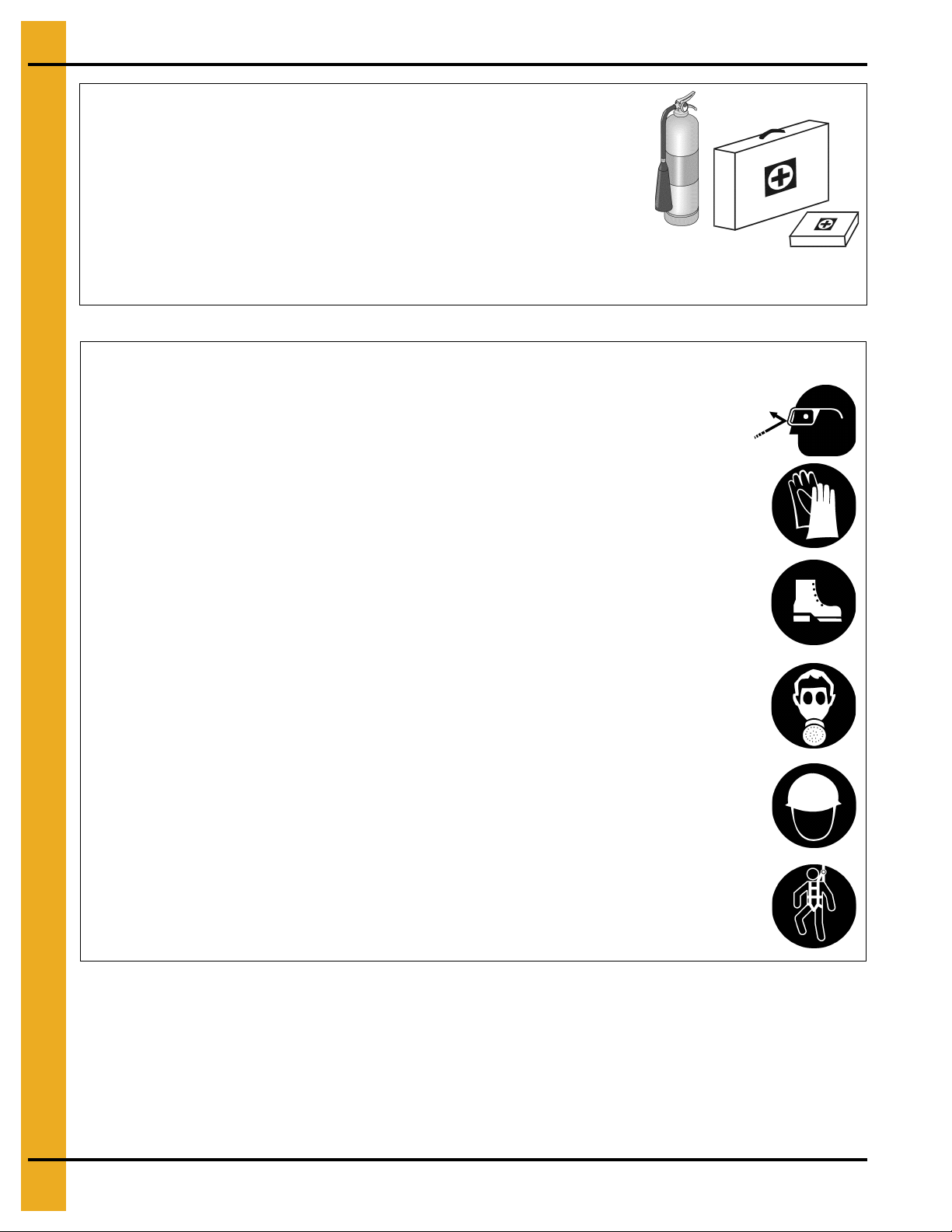
Prepare for Emergencies
Be prepared if fire starts.
Keep a first aid kit and fire extinguisher handy.
Keep emergency numbers for doctors, ambulance service,
hospital, and fire department near your telephone.
Keep Emergency Equipment
Quickly Accessible
Wear Protective Clothing
Wear close-fitting clothing and safety equipment appropriate
to the job.
Remove all jewelry.
Tie long hair up and back.
Wear safety glasses at all times to protect eyes from debris.
Wear gloves to protect your hands from sharp edges on
plastic or steel parts.
Wear steel-toed boots to help protect your feet from falling
debris. Tuck in any loose or dangling shoestrings.
A respirator may be needed to prevent breathing potentially
toxic fumes and dust.
Wear a hard hat to help protect your head.
Wear appropriate fall protection equipment when working at
elevations greater than six feet (6').
Eye Protection
Gloves
Steel-Toed Boots
Respirator
Hard Hat
Fall Protection
8 PNEG-4042 40 Series 42' and 48' Diameter Bins
Page 9

1. Safety
Safety Sign-Off Sheet
As a requirement of O.S.H.A., it is necessary for the employer to train the employee in the safe operating
and safety procedures for this equipment. This sign-off sheet is provided for your convenience and
personal record keeping. All unqualified persons are to stay out of the work area at all times. It is strongly
recommended that another qualified person who knows the shut down procedure be in the area in the
event of an emergency.
Date Employee Name Supervisor Name
PNEG-4042 40 Series 42' and 48' Diameter Bins 9
Page 10
2. Decals
Excessive vacuum (or pressure) may
damage roof. Use positive aeration
system. Make sure all roof vents are
open and unobstructed. Start roof
fans when supply fans are started.
Do not operate when conditions exist
that may cause roof vent icing.
DC-969
CAUTION
GSI Group, Inc. 217-226-4421
The manufacturer does not warrant any roof damage caused by excess ive v acuum or internal
pressure from fans or other air moving systems. Adequate ventilation and/or “makeup air”
devices should be provided for all powered air handling systems. The manufacturer does not
recommend the use of downward flow systems (suction). Severe roof damage can result from
any blockage of air passages. Running fans durin g high humidity/cold weather conditions can
cause air exhaust or intake ports to freeze.
Roof Damage Warning and Disclaimer
10 PNEG-4042 40 Series 42' and 48' Diameter Bins
Page 11
2. Decals
ATTENTION: The decal shown below should be present on the outside of the door cover of the 2 ring,
24" porthole door cover and the roof manway cover. If a decal has been damaged or is missing in any of
these locations, contact the manufacturer for a free replacement decal.
GSI Decals
1004 E. Illinois St.
Assumption, IL. 62510
Phone: 1-217-226-4421
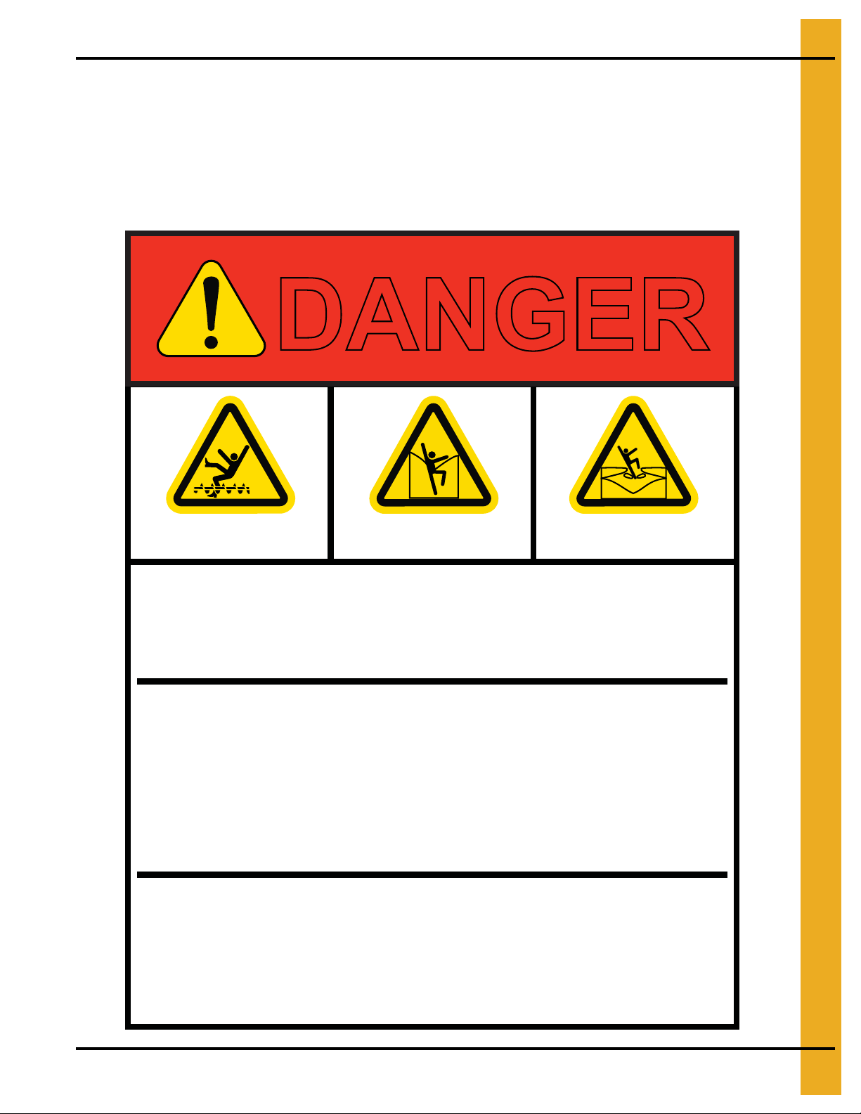
DANGER
Rotating flighting will
kill or dismember.
Flowing material will
trap and suffocate.
Crusted material will
collapse and suffocate.
Keep clear of all augers.
DO NOT ENTER this bin!
If you must enter the bin:
1. Shut off and lock out all power.
2. Use a safety harness and safety line.
3. Station another person outside the bin.
4. Avoid the center of the bin.
5. Wear proper breathing equipment or respirator.
Failure to heed these
warnings will result in
serious injury or death.
GSI GROUP, INC. 217-226-4421
PNEG-4042 40 Series 42' and 48' Diameter Bins 11
DC-GBC-1A
Page 12
2. Decals
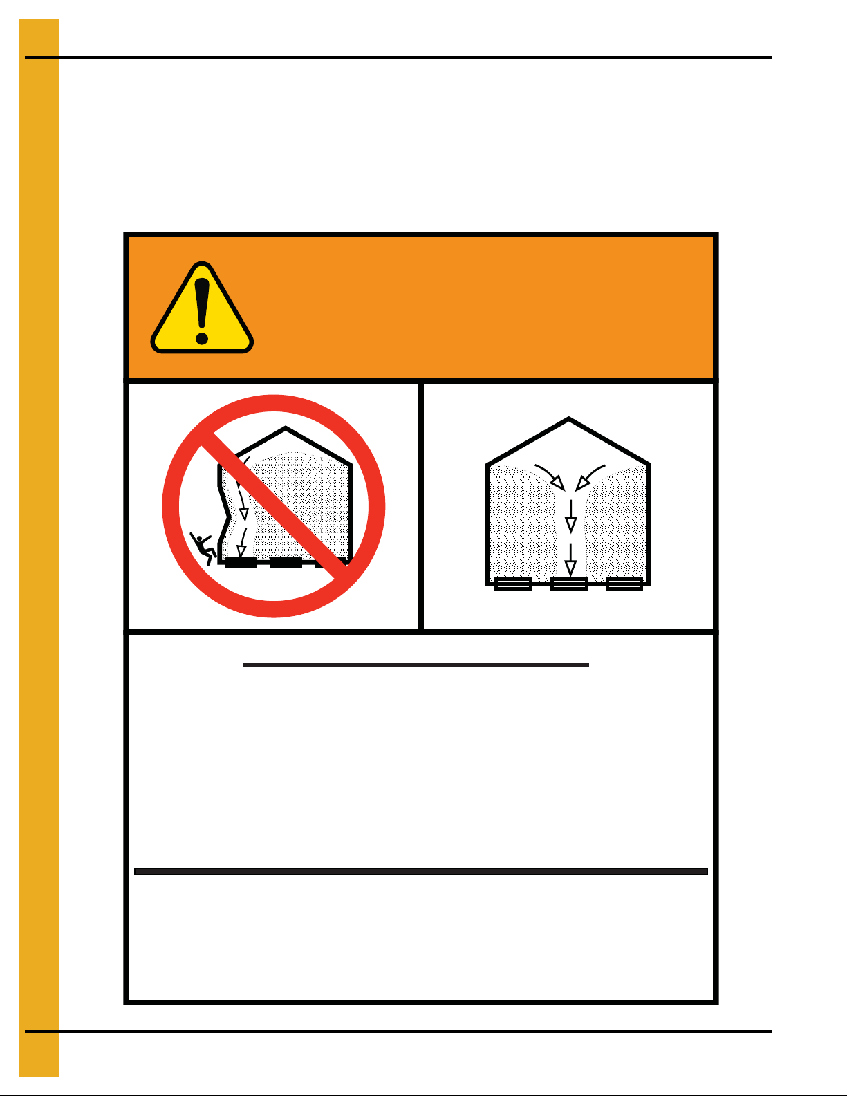
WARNING
GSI GROUP, INC. 217-226-4421
1. Use CENTER FLOOR OUTLET ONLY until NO grain
remains above this outlet.
2. Side floor outlets to be used ONLY when above
condition is satisfied.
3. Lock all side floor outlets to avoid accidental
premature use.
4. See manufacturers instructions for proper use of
factory supplied sidedraw (wall) discharge systems.
UNLOADING INSTRUCTIONS:
Failure to heed these warnings
could result in serious injury, death,
structural damage or collapse of tank.
DC-GBC-2A
ATTENTION: The decal shown below should be present on the outside of the door cover of the 2 ring,
24" porthole door cover and the roof manway cover. If a decal has been damaged or is missing in any of
these locations, contact the manufacturer for a free replacement decal.
GSI Decals
1004 E. Illinois St.
Assumption, IL. 62510
Phone: 1-217-226-4421
12 PNEG-4042 40 Series 42' and 48' Diameter Bins
Page 13
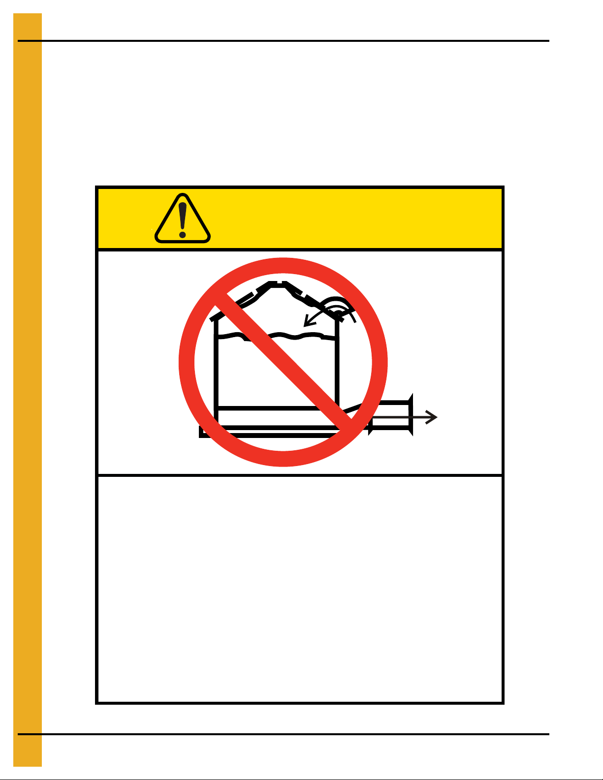
Overfill Warning
WARNING
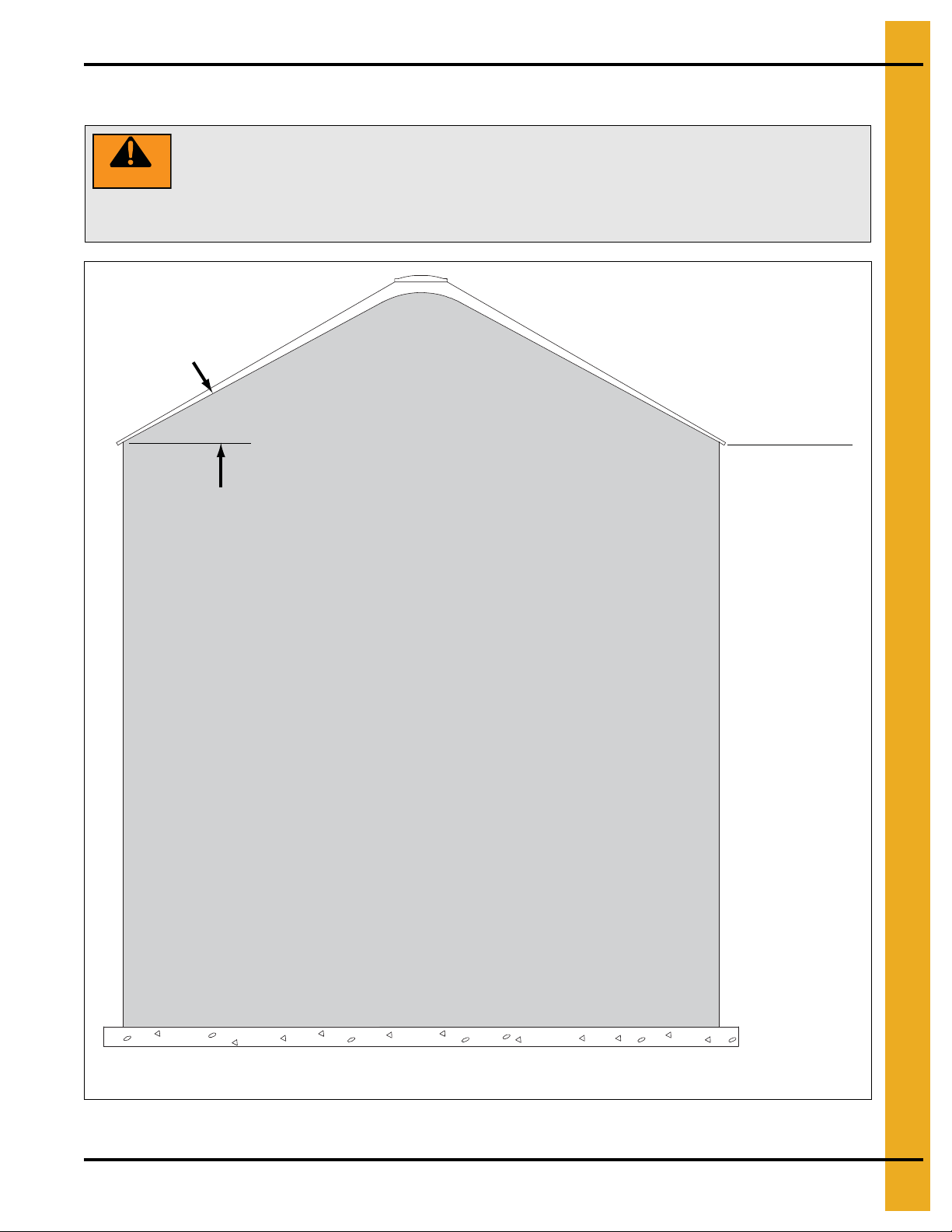
DO NOT OVERFILL BIN. Stored grain, although heaped in the center, should
be no higher than the roof eaves at the outer edge. (See Figure 2A.) Filling the bin
above this point creates excessive internal pressure and may cause swelling and
eventual roof failure. The overfilling of a bin may also cause the blockage of roof
vents and eaves, which will lead to a build-up of air pressure causing roof damage.
27°
Roof eave height
(Based on grain with an angle of repose of 27°.)
2. Decals
PNEG-4042 40 Series 42' and 48' Diameter Bins 13
Figure 2A Maximum Bin Capacity
Page 14

3. General Overview
General Information
General information, overview and instructions needed before performing work.
Read this manual carefully. This manual will provide instructions on building the sidewall and stiffeners.
You will also need to consult other instructions in building the tank.
These include, but may not be limited to:
1. A stiffener and sidewall gauge layout chart. If such a chart is not included with this manual,
contact GSI.
2. Roof instructions must be followed. Roof instructions are included in this manual.
3. Ladders, roof stairs, roof handrails and other products are covered by separate instruction manuals.
Consult the appropriate accessory manual. Inside ladder instructions are included in this manual.
4. Aeration systems and transitions are to be installed according to the instructions provided with the
system or transition.
5. It is critical that the anchor bolts are installed and spaced correctly.
Anchor Bolt Charts
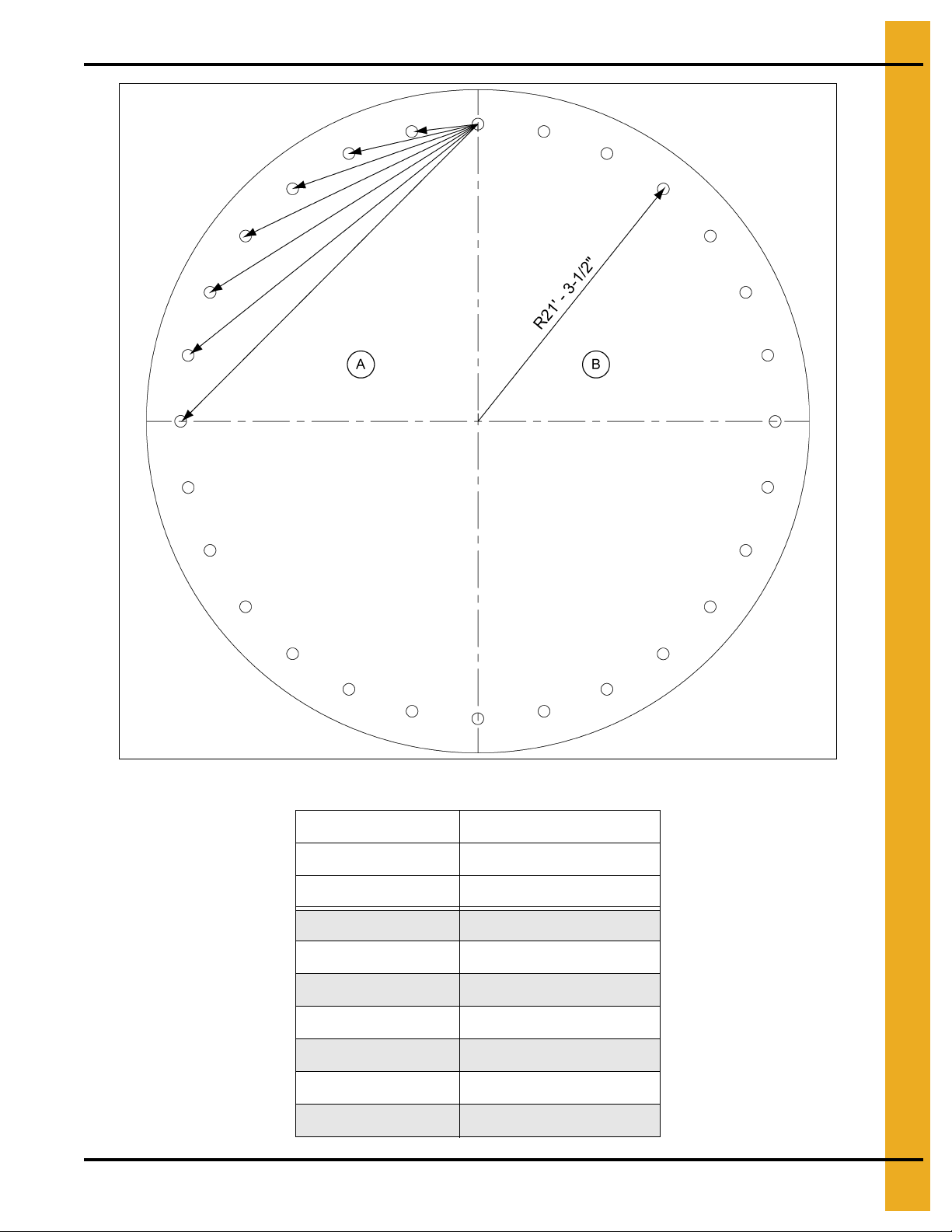
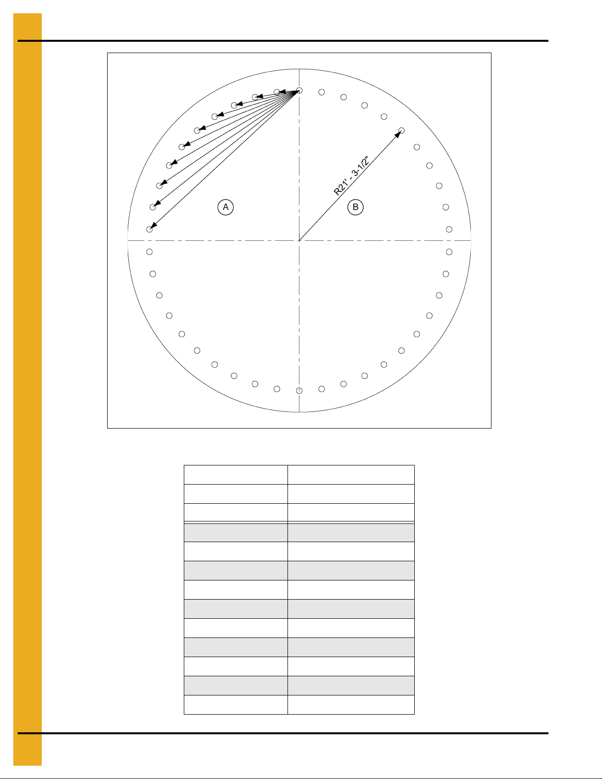
Prior to setting any anchor bolts, you must be sure to have the correct anchor bolt placement. This is very
critical for stiffener alignment during bin erection.
NOTE: Refer to the proper chart to find the anchor chord dimensions that correspond to the bin that is
being built. (See Pages 15-18.)
Start with one anchor bolt and work from it to the left to locate one quarter of the anchor bolts the n to the
right to locate another quarter of the bolts. Working off of the last a nchor bolts in each quarte r, locate the
remaining anchor bolts in the last two (2) quarters.
14 PNEG-4042 40 Series 42' and 48' Diameter Bins
Page 15
3. General Overview
Anchor chord dimensions
Bolt radius
PNEG-4042 40 Series 42' and 48' Diameter Bins 15
Figure 3A Anchor Bolt Chords for 42' Diameter 2 Post Bin
Diameter 42'
# of Anchors 28
Bolt Radius 21' - 3-1/2"
Chord 1 4' - 9-1/4"
Chord 2 9' - 5-3/4"
Chord 3 14'-3/4"
Chord 4 18' - 5-11/16"
Chord 5 22' - 7-7/8"
Chord 6 26' - 6-3/4"
Chord 7 30' - 1-5/16"
Page 16
3. General Overview
Anchor chord dimensions
Bolt radius
Figure 3B Anchor Bolt Chords for 42' Diameter 3 Post Bin
Diameter 42'
# of Anchors 42
Bolt Radius 21' - 3-1/2"
Chord 1 3' - 2-3/16"
Chord 2 6' - 4-3/16"
Chord 3 9' - 5-3/4"
Chord 4 12' - 6-5/8"
Chord 5 15' - 6-11/16"
Chord 6 18' - 5-11/16"
Chord 7 21' - 3-1/2"
Chord 8 23' - 11-13/16"
Chord 9 26' - 6-9/16"
Chord 10 28' - 11-9/16"
16 PNEG-4042 40 Series 42' and 48' Diameter Bins
Page 17
3. General Overview
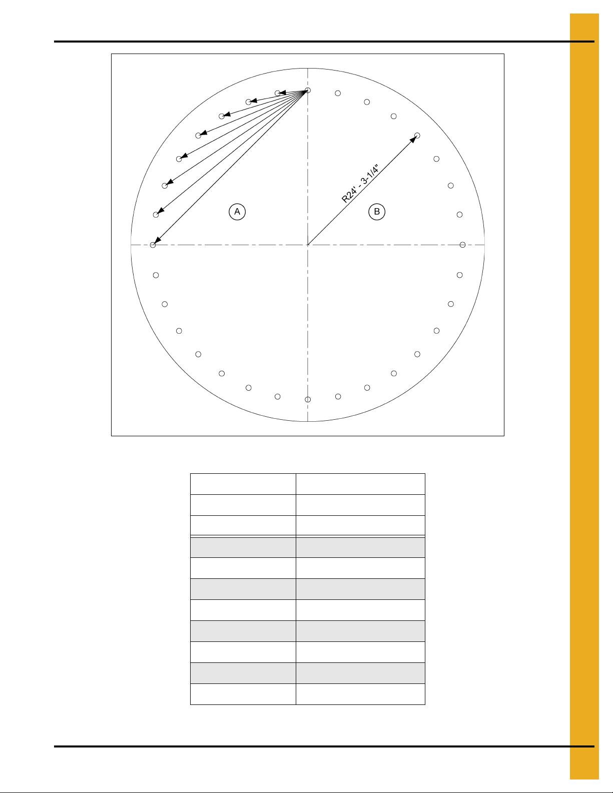
Anchor chord dimensions
Bolt radius
Figure 3C Anchor Bolt Chords for 48' Diameter 2 Post Bin
Diameter 48'
# of Anchors 32
Bolt Radius 24' - 3-1/4"
Chord 1 4' - 9-1/8"
Chord 2 9' - 5-11/16"
Chord 3 14' - 1-1/8"
Chord 4 18' - 6-15/16"
Chord 5 22' - 10-5/8"
Chord 6 26' - 11-11/16"
Chord 7 30' - 9-9/16"
Chord 8 34' - 3-15/16"
PNEG-4042 40 Series 42' and 48' Diameter Bins 17
Page 18
3. General Overview
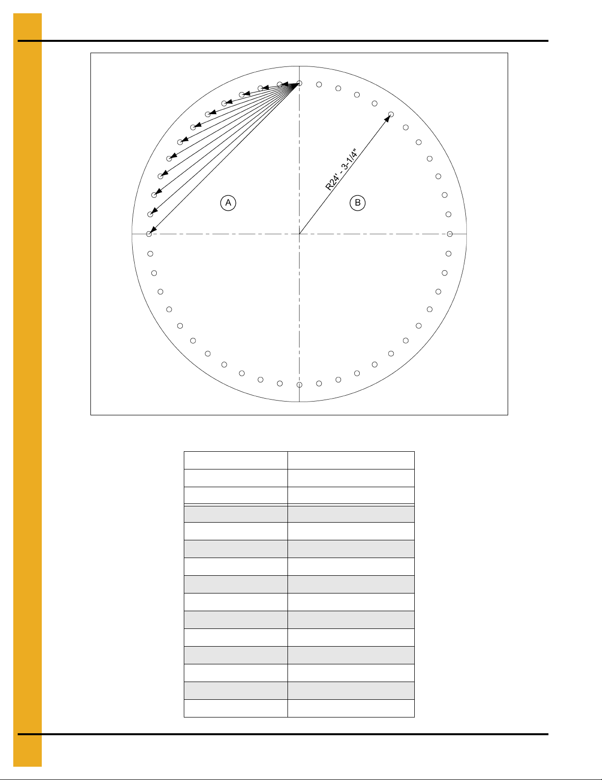
Anchor chord dimensions
Bolt radius
Figure 3D Anchor Bolt Chords for 48' Diameter 3 Post Bin
Diameter 48'
# of Anchors 48
Bolt Radius 24' - 3-1/4"
Chord 1 3' - 2-1/8"
Chord 2 6' - 4-1/16"
Chord 3 9' - 5-11/16"
Chord 4 12' - 6-13/16"
Chord 5 15' - 7-5/16"
Chord 6 18' - 6-15/16"
Chord 7 21' - 5-11/16"
Chord 8 24' - 3-5/16"
Chord 9 26' - 11-11/16"
Chord 10 29' - 6-11/16"
Chord 11 32' - 1/8"
Chord 12 34' - 3-15/16"
18 PNEG-4042 40 Series 42' and 48' Diameter Bins
Page 19

Tools Required for Construction
General tools needed to perform this construction.
1. Combination wrench set 7/16" to 1"
2. Alignment punches 12" long
3. 1/2" Drive socket set and ratchet
4. Nail aprons or tool pouches to hold supplies
5. Gloves for hand protection
6. Tape measure
7. 1/2" Drive electric or pneumatic torque gun with variable impact capabilities
8. 1/2" Drive impact socket set
9. Lifting jacks
10. Center pole roof support
11. Step ladders
3. General Overview
12. Large C-clamp or welding V-grip for clamping
NOTE: Quantities required will depend on the number of workers and size of the bin.
Guidelines for Proper Storage of Grain Bin Materials Prior
to Construction
Storage of the build materials prior to construction is important. Do not to allow moisture to remain
between sheets or panels.
Wet storage stain (rust) will develop when closely packed bundles of galvanized material, such as sidewall
and roof sheets, have moisture present. Inspect roof and sidewall bundles on arrival for any moisture. If
moisture is present, it must not be allowed to remain between the sheets. Separate the sheets or panels
immediately and wipe them down. Spray with a light oil or diesel fuel.
If possible, sidewall bundles, roof sheets and other closely packed galvanized materials should be stored
in a dry, climate controlled building. If outdoor storage is unavoidable, the materials should be stored so
that they are raised above the ground and vegetation. Any stacking and spacing materials should not be
corrosive or wet. Be sure to protect materials from the weather, but permit air movement around the
bundles if possible.
Storing roof bundles and sidewall sheets at a slight incline can also help minimize the presence of
moisture. Storing the bundles with the center of the dome up (like an arch) is one option for minimizing
moisture during storage. Sidewall bundles can also be stored on edge but must be secured so that they
do not fall over and cause injury.
If “white rust” or “wet storage stain” occurs, contact the manufacturer immediately about ways to minimize
the adverse effect upon the galvanized coating.
PNEG-4042 40 Series 42' and 48' Diameter Bins 19
Page 20

3. General Overview
Guidelines for Construction Procedures and Lifting Jack Usage
The following procedure is a guideline when using the required lifting jack. Follow this general guideline
when lifting the bin as sidewalls are being installed.
NOTE: The roof and the top ring for odd ringed bins or the roof and 2 rings for even ringed bins, will be
installed prior to the beginning of bin lifting procedures. Refer to all other procedures on sidewall
and stiffener installation prior to the start of construction.
IMPORTANT: Begin building with the bin oriented for doors and material handling equipmen t to be in the
correct position when bin construction is complete.
1. Consider the starting location of the bin, relative to the location of doors and other accessories.
Proper placement of lifting jacks in relationship to anchor bolts could make a difference in final
locations. Note that the sidewall sheets will be staggered.
2. The bin is lifted by the use of lifting jacks. Lifting jacks are used to slowly and evenly lift the bin during
construction. Lifting jacks must be properly sized and designed to carry all loads and job site
conditions associated with the construction of the bin.
The number of lifting jacks required is best determined by personal experience and expertise.
Factors such as bin size, jack design, construction conditions, support surface, etc., are all to be
considered when deciding how many to use. If in doubt, use one jack on every sheet. The lifting jack
must be adequate to carry all loads. Heavy duty jacks, generally hydraulic or electric powered in the
case of large bins, should be used for commercial installation. All jacks should be secured with
braces or otherwise maintained in a stable condition.
Lifting of the bins should not be done under windy conditions.
Follow the jack manufacturers recommendations on capacity and operations.
3. Lifting brackets should be attached through the stiffener bolt holes. Normally you will need to attach
to at least four (4) bolts per stiffener.
4. Raise the bin just high enough to assemble the next ring. When lifting the bin, all jacks must lift at
an equal rate. Monitor the lift to ensure even lifting is occurring.
5. To the inside of the first ring, bolt the next ring. Be sure to stagger the sheets and select the proper
gauge material.
6. Lower the bin onto the foundation after assembling and tightening bolts on the new ring or rings.
7. Attach stiffeners to the body sheets every two (2) tiers (on the external surface of the bin). You may
want to leave sheets loose to make the attachment of the stiffeners easier.
8. Now re-bolt the lifting brackets to the lowest ring in place thus far. Continue ring additions by
repeating Step 5 and Step 6.
9. Add inside and outside ladders as you continue to raise the bin. (Refer to the manual supplied with
the ladder).
10. Lower the tank and secure to the foundation before leaving the job site.
11. At the completion of the tank, set stiffeners over the anchor bolts and measure the tank to ensure it
is in a round condition. Consult with GSI for questions on tolerances.
NOTE: For 2 ring doors or vehicle traffic doors, special placement issues may apply. Consult the special
instructions provided with 2 ring doors or vehicle traffic doors for these options.
20 PNEG-4042 40 Series 42' and 48' Diameter Bins
Page 21
3. General Overview
Guidelines for Placement of the Decal Sidewall Sheet
Use the following as a general guideline the proper decal sheet placement.
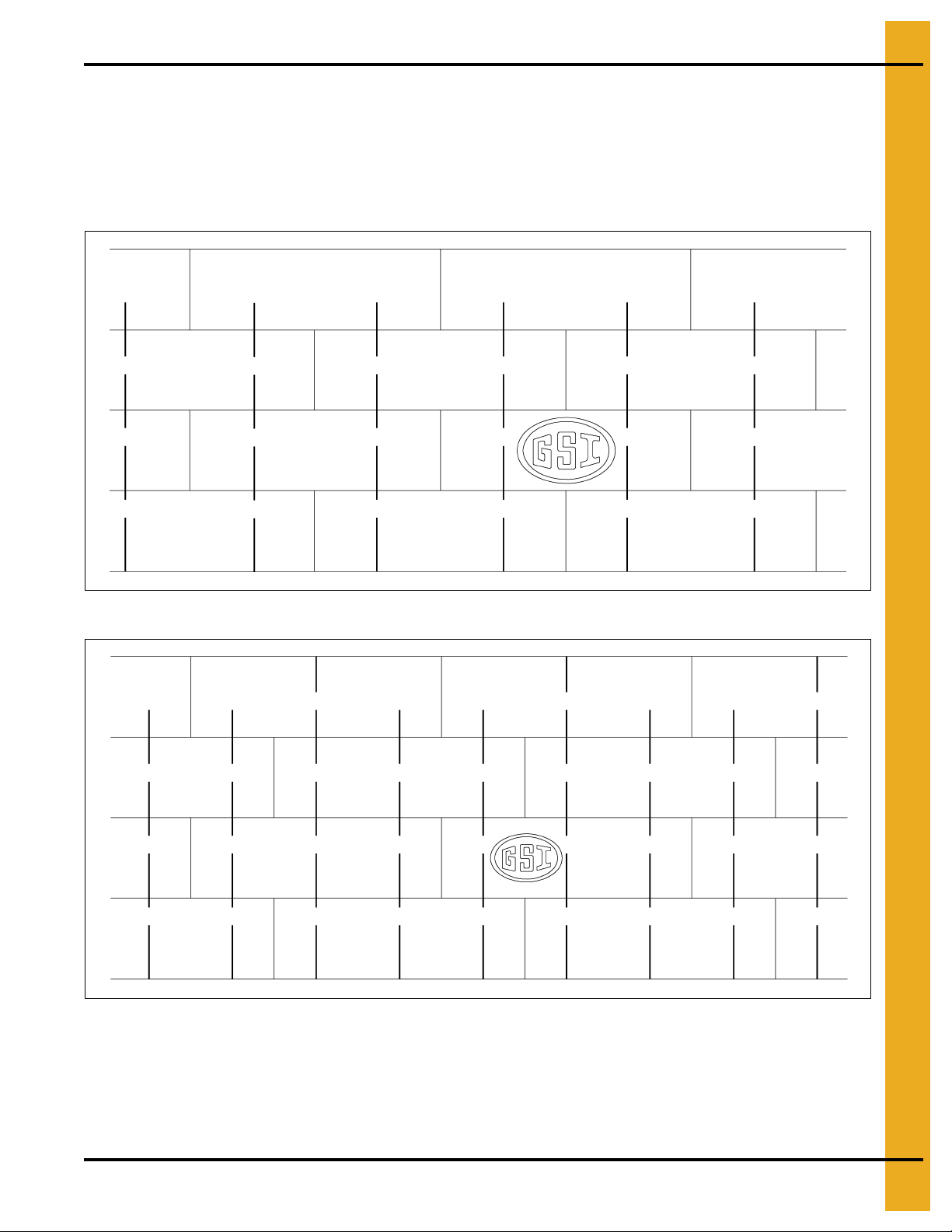
NOTE: Refer to the stiffener to sidewall attachment detail and specif ic gauge sheet for the bin. The decal
sheets are located in the third ring from the top. They are to be spaced evenly around the diameter
of the bin.
Figure 3E 2 Post bin with two (2) rows of stiffeners used on each sidewall sheet.
Figure 3F 3 Post bin with three (3) rows of stiffeners used on each sidewall sheet.
NOTE: Dashed lines represent stiffener locations.
PNEG-4042 40 Series 42' and 48' Diameter Bins 21
Page 22
4. Bolt and Nut Usage
Hardware Requirements for Sidewalls and Stiffeners
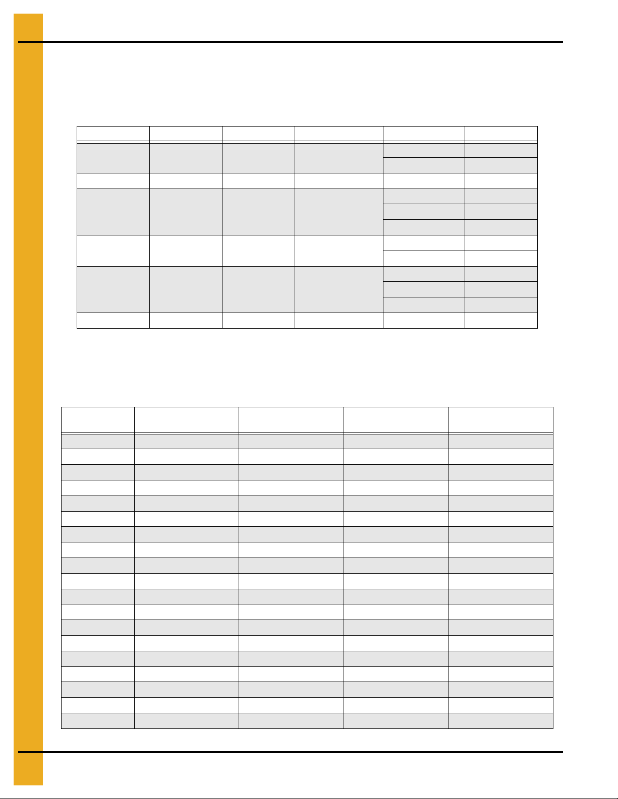
Bolt and Nut Pairings
This chart lists the correct nut to use with each size of bolt.
Nut Part # Nut Size Type Hex or Flanged Bolt Size Bolt Part #
S-396 5/16" YDP Hex
S-3611 5/16" YDP Flanged 5/16" x 1" S-10260
S-456 3/8" YDP Hex
S-9426 3/8" JS Flanged
S-9281 7/16" JS Hex
S-10251 7/16" JS Flanged (Special) 7/16" x 1-1/4" S-10250
5/16" x 3/4" S-275
5/16" x 1-1/4" S-277
3/8" x 1" S-7487
3/8" x 1-1/2" S-7488
3/8" x 2" S-10165
3/8" x 1" S-7485
3/8" x 1-1/2" S-7488
7/16" x 1-1/2" S-10262
7/16" x 2" S-9389
7/16" x 3-1/4" S-10261
Hardware for 2 Post Sidewall Sheets on Bins 18' to 60' in Diameter
Refer to the chart for hardware requirements for 2 post sidewall sheet connections on bins 18' to
60' diameter.
Gauge
20 3/8" x 1" (10) 3/8" x 1" (24) 3/8" x 1" (24) 3/8" x 1" (2)
19 3/8" x 1" (10) 3/8" x 1" (24) 3/8" x 1" (24) 3/8" x 1" (2)
18 3/8" x 1" (10) 3/8" x 1" (24) 3/8" x 1" (24) 3/8" x 1" (2)
17 3/8" x 1" (10) 3/8" x 1" (36) 3/8" x 1" (24) 3/8" x 1" (2)
16 3/8" x 1" (10) 3/8" x 1" (36) 3/8" x 1" (24) 3/8" x 1" (2)
15 3/8" x 1" (22) 3/8" x 1" (48) 3/8" x 1" (24) 3/8" x 1" (2)
14 3/8" x 1" (22) 3/8" x 1" (48) 3/8" x 1" (24) 3/8" x 1" (2)
13 3/8" x 1" (22) 3/8" x 1" (48) 3/8" x 1" (24) 3/8" x 1" (2)
12 3/8" x 1" (22) 3/8" x 1" (48) 3/8" x 1" (24) 3/8" x 1" (2)
11 3/8" x 1" (22) 3/8" x 1" (48) 3/8" x 1" (24) 3/8" x 1" (2)
10 3/8" x 1" (22) 3/8" x 1" (48) 3/8" x 1" (24) 3/8" x 1" (2)
9 3 /8" x 1" (22) 3/8" x 1" (48) 3/8" x 1-1/2" (24) 3/8" x 1-1/2" (2)
8 3/8" x 1" (22) 3/8" x 1" (48) 3/8" x 1-1/2" (24) 3/8" x 1-1/2" (2)
6 3/8" x 1-1/2" (22) 3/8" x 1-1/2" (48) 3/8" x 1-1/2" (24) 3/8" x 1-1/2" (2)
5 3/8" x 1-1/2" (22) 3/8" x 1-1/2" (48) 3/8" x 1-1/2" (24) 3/8" x 1-1/2" (2)
11L 3/8" x 1-1/2" (22) 3/8" x 1-1/2" (48) 3/8" x 1-1/2" (24) 3/8" x 1-1/2" (2)
10L 3/8" x 1-1/2" (22) 3/8" x 1-1/2" (48) 3/8" x 1-1/2" (24) 3/8" x 1-1/2" (2)
9L 3/8" x 1-1/2" (24) 7/16" x 1-1/2" (48) 3/8" x 1-1/2" (24) 3/8" x 1-1/2" (6)
8L 3/8" x 1-1/2" (24) 7/16" x 1-1/2" (48) 3/8" x 1-1/2" (24) 3/8" x 1-1/2" (6)
Horizontal Seam
Bolt Size (Quantity)
Vertical Seam Bolt
Size (Quantity)
Stiffener to Sidewall
Bolt Size (Quantity)
Overlap Seam Bolt
Size (Quantity)
22 PNEG-4042 40 Series 42' and 48' Diameter Bins
Page 23

4. Bolt and Nut Usage
Hardware for 3 Post Sidewall Sheets on Bins that are 18' to 90' Diameter and
105' Bins that are 27 Rings and Shorter
Refer to the chart for the hardware requirements for 3 post sidewall sheet connections on bins
18' to 90' diameter. Refer to the chart for the hardware requirements for 3 post sidewall sheet connections
on bins 105' diameter that are 27 rings and shorter.
Gauge
20 3/8" x 1" (10) 3/8" x 1" (24) 3/8" x 1" (12) 3/8" x 1" (2)
19 3/8" x 1" (10) 3/8" x 1" (24) 3/8" x 1" (12) 3/8" x 1" (2)
18 3/8" x 1" (10) 3/8" x 1" (24) 3/8" x 1" (12) 3/8" x 1" (2)
17 3/8" x 1" (10) 3/8" x 1" (36) 3/8" x 1" (12) 3/8" x 1" (2)
16 3/8" x 1" (10) 3/8" x 1" (36) 3/8" x 1" (12) 3/8" x 1" (2)
15 3/8" x 1" (22) 3/8" x 1" (48) 3/8" x 1" (12) 3/8" x 1" (2)
14 3/8" x 1" (22) 3/8" x 1" (48) 3/8" x 1" (12) 3/8" x 1" (2)
13 3/8" x 1" (22) 3/8" x 1" (48) 3/8" x 1" (12) 3/8" x 1" (2)
12 3/8" x 1" (22) 3/8" x 1" (48) 3/8" x 1" (12) 3/8" x 1" (2)
11 3/8" x 1" (22) 3/8" x 1" (48) 3/8" x 1" (12) 3/8" x 1" (2)
10 3/8" x 1" (22) 3/8" x 1" (48) 3/8" x 1" (12) 3/8" x 1" (2)
9 3/8" x 1" (22) 3/8" x 1" (48) 3/8" x 1-1/2" (12) 3/8" x 1-1/2" (2)
8 3/8" x 1" (22) 3/8" x 1" (48) 3/8" x 1-1/2" (12) 3/8" x 1-1/2" (2)
Horizontal Seam
Bolt Size (Quantity)
Vertical Seam Bolt
Size (Quantity)
Stiffener to Sidewall
Bolt Size (Quantity)
Overlap Seam Bolt
Size (Quantity)
6 3/8" x 1-1/2" (22) 3/8" x 1-1/2" (48) 3/8" x 1-1/2" (12) 3/8" x 1-1/2" (2)
5 3/8" x 1-1/2" (22) 3/8" x 1-1/2" (48) 3/8" x 1-1/2" (12) 3/8" x 1-1/2" (2)
1 1L 3/8" x 1-1/2" (22) 3/8" x 1-1/2" (48) 3/8" x 1-1/2" (12) 3/8" x 1-1/2" (2)
10L 3/8" x 1-1/2" (22) 3/8" x 1-1/2" (48) 3/8" x 1-1/2" (12) 3/8" x 1-1/2" (2)
9L 3/8" x 1-1/2" (24) 7/16" x 1-1/2" (48) 3/8" x 1-1/2" (24) 3/8" x 1-1/2" (6)
8L 3/8" x 1-1/2" (24) 7/16" x 1-1/2" (48) 3/8" x 1-1/2" (24) 3/8" x 1-1/2" (6)
PNEG-4042 40 Series 42' and 48' Diameter Bins 23
Page 24
4. Bolt and Nut Usage
Under no condition shall any other bolts be substituted for those supplied by GSI.
CAUTION
Grade 2 Bolts
Grade 2 bolts are designated with a plain head and are not used in GSI grain bins.
Grade 5 Bolts
Grade 5 bolts are designated by three (3) slash marks on the head. All 5/16" diameter
bolts are to be grade 5 or higher.
Grade 8 Bolts
Grade 8 bolts are designated by six (6) slash marks evenly spaced out around the head
of the bolt. All 3/8", 7/16" and 1/2" diameter bolts are to be grade 8 or grade 8.2.
Grade 8.2 Bolts
Grade 8.2 bolts are designated by six (6) slash marks on the head in a sunrise pattern.
All 3/8", 7/16" and 1/2" diameter bolts are to be grade 8 or grade 8.2.
Bolt Torque Specifications
The specification torque table below will help the installer determine how tight a specific bolt must be.
A bolt that has been over tightened can be just as dangerous as one that ha s not been tightened enough.
IMPORTANT: Bolts should not be tightened in excess of the torque specifications chart listed below.
Bolt Minimum Torque Maximum Torque
Sealing Joints
(Joints with
Sealing Washers)
ft./lbs. N-m ft./lbs. N-m
5/16"-18 JS Grade 8 with Seal 20 27 - - 25 34 - -
3/8"-16 JS Grade 8 with Seal 30 41 - - 35 47 - 7/16"-14 JS Grade 8 with Seal 50 68 - - 60 81 - 3/8"-16 YDP Grade 8 Flanged - - 45 61 - - 55 75
7/16"-14 YDP Grade 8 Flanged - - 85 115 - - 95 129
1/2"-13 YDP Grade 8 Flanged - - 125 169 - - 140 189
Structural Joints
(Joints without any
Sealing Washers)
Sealing Joints
(Joints with
Sealing Washers)
ft./lbs. N-m ft./lbs. N-m
Structural Joints
(Joints without any
Sealing washers)
Identifying Bolt Grades
Bolts are identified by grade (or hardness), the grade can be identified by the markings on the head of the
bolt. These markings will be in the form of slash marks and patterns. Use the following as a guide to
determine the correct bolt grade.
NOTE: Refer to 2.66" commercial tank bolting requirements for complete bolt usage.
24 PNEG-4042 40 Series 42' and 48' Diameter Bins
Page 25
4. Bolt and Nut Usage
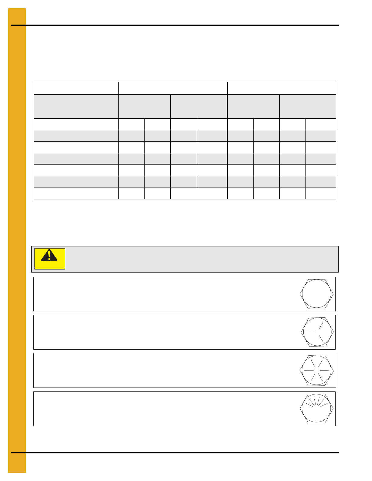
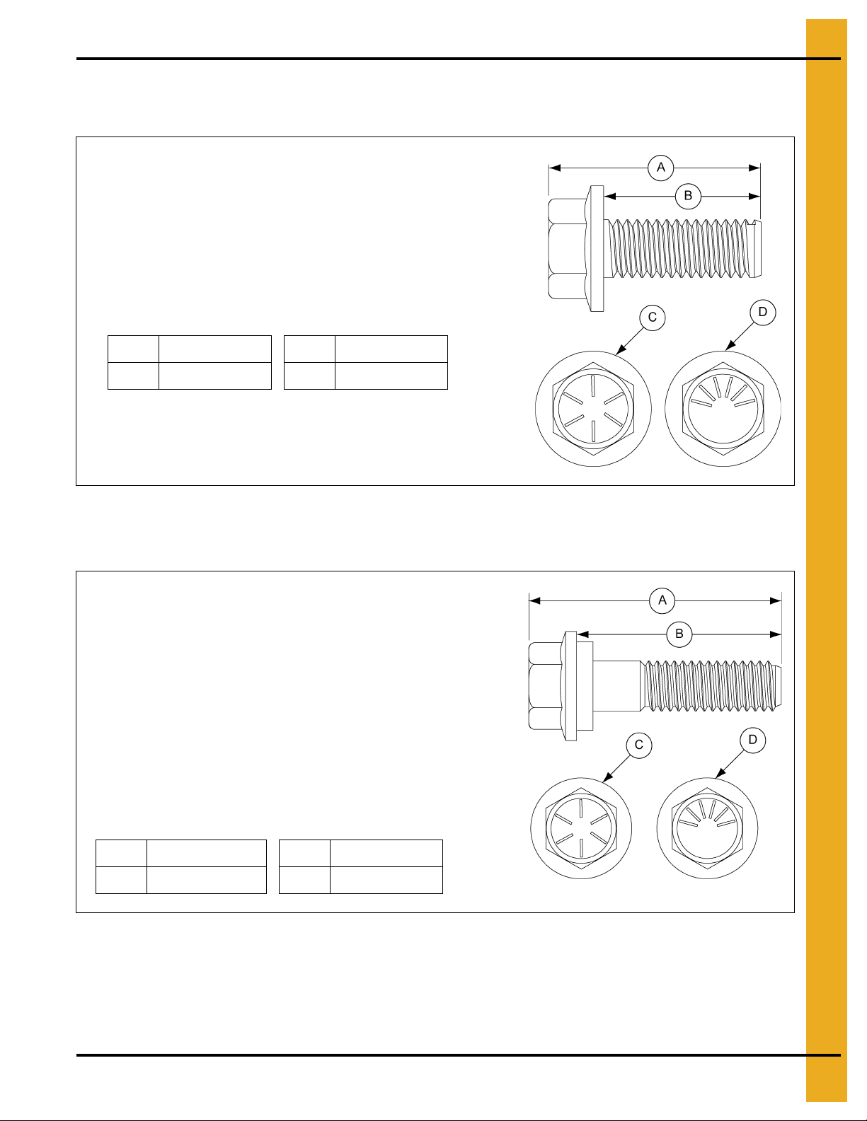
Bolt (S-275) is used in the following locations:
1. Use in accessories.
2. The color of bucket lid is dark blue.
A 0.945" (2.40 cm) C Grade 5
B 0.750" (1.90 cm)
D Grade 5
Bolt (S-10260) is used in the following locations:
1. Use to connect roof panels together where they overlap.
2. Use when connecting eave angle to sidewall sheet.
3. The color of the bucket lid is lime green.
4. Use to connect eave clip to sidewall sheet on bins that are
48' diameter and smaller.
5. Use to attach roof panels to flashing on bins that are
48' diameter and smaller.
A 1.300" (3.30 cm) C Grade 8
B 1.000" (2.54 cm)
D Grade 8.2
Bolt Identification
Use the following information to identify the bolts and where each must be used during installation.
Bolt (S-275)
An S-275 is a 5/16" x 3/4" YDP bolt that is pre-assembled with a sealing washer.
Bolt (A-10260)
An S-10260 is a 5/16" x 1" JS bolt that is pre-assembled with a sealing washer.
PNEG-4042 40 Series 42' and 48' Diameter Bins 25
Page 26
4. Bolt and Nut Usage
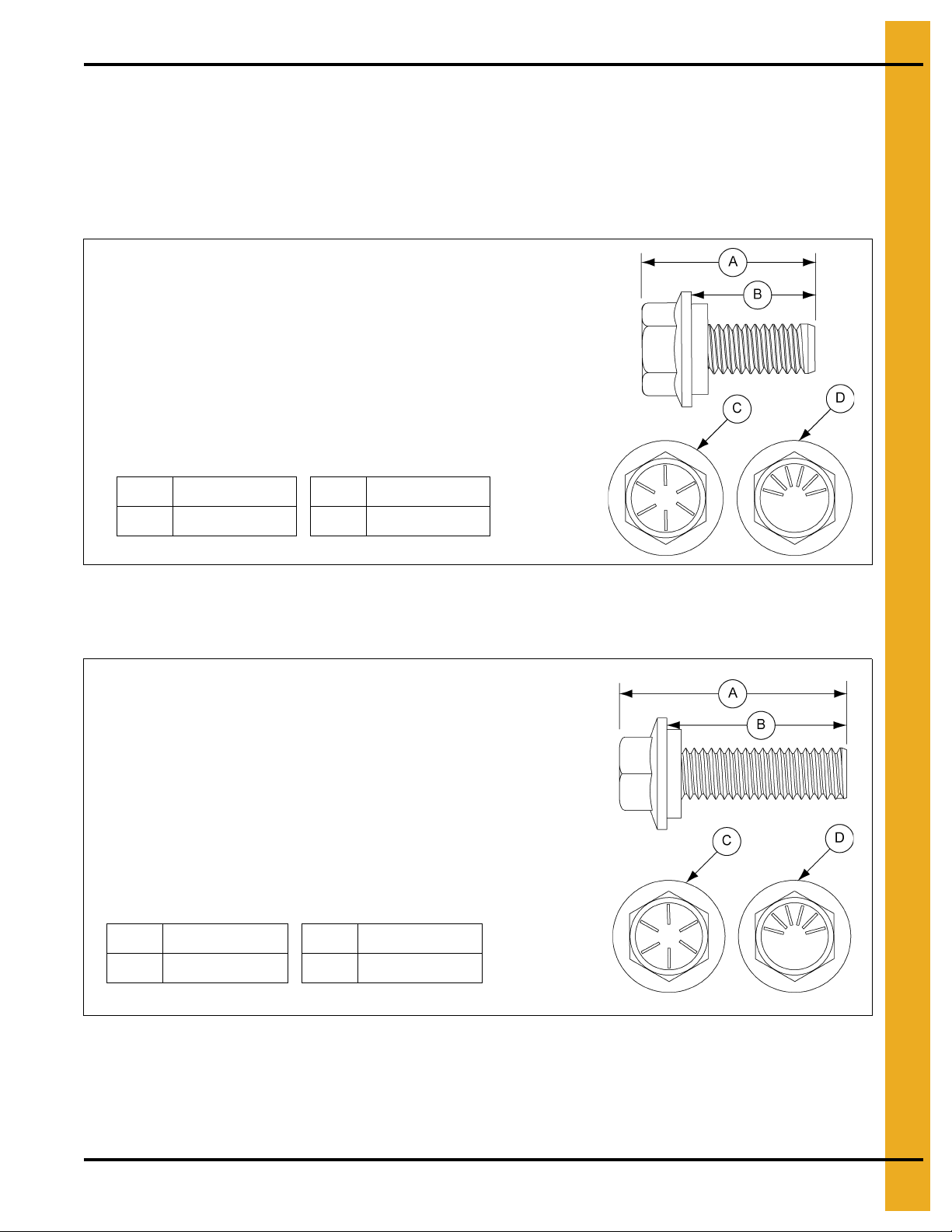
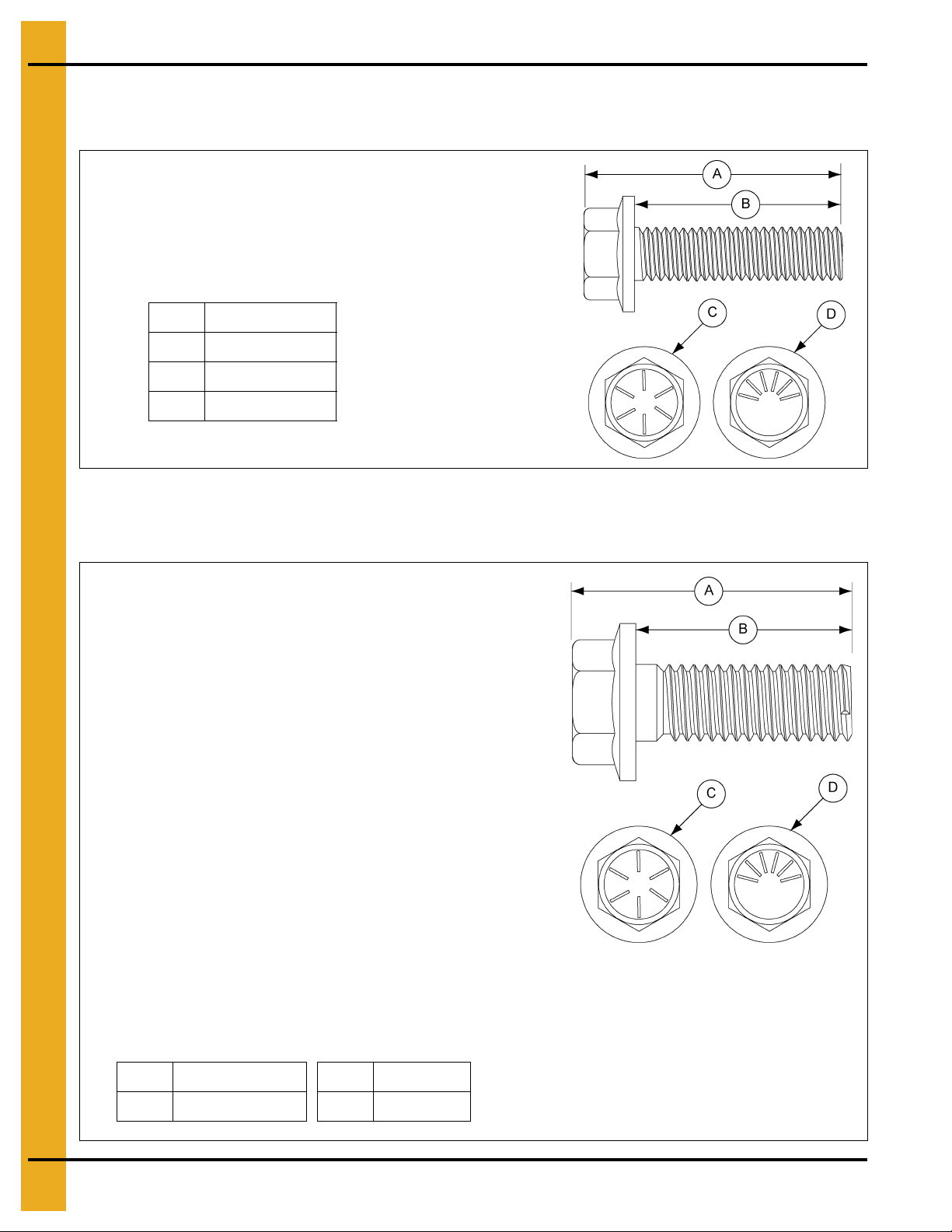
Bolt (S-277) is used in the following locations:
1. Used in accessories.
2. The color of the bucket lid is black.
A 1.445" (3.67 cm) C Grade 5
B 1.250" (3.17 cm)
DGrade 5
Bolt (S-7487) is used in the following locations:
1. Use in all sidewall connections for 20 gauge through
10 gauge sidewall to sidewall sheets.
2. Use for horizontal and vertical seam connections for
9 gauge through 8 gauge sidewall sheets.
3. Use when attaching base angle to sidewall sheet on flat
bottom bins.
4. The color of bucket lid is grey.
NOTE: Do not use to splice the stiffeners together on the
flanges where they connect to each other or the
splice plates.
A 1.350" (3.43 cm) C Grade 8
B 1.000" (2.54 cm)
D Grade 8.2
Bolt (S-277)
An S-277 is a 5/16" x 1-1/4" YDP bolt pre-assembled with a sealing washer.
Bolt (S-7487)
An S-7487 is a 3/8" x 1" JS bolt that is pre-assembled with a sealing washer.
26 PNEG-4042 40 Series 42' and 48' Diameter Bins
Page 27
4. Bolt and Nut Usage
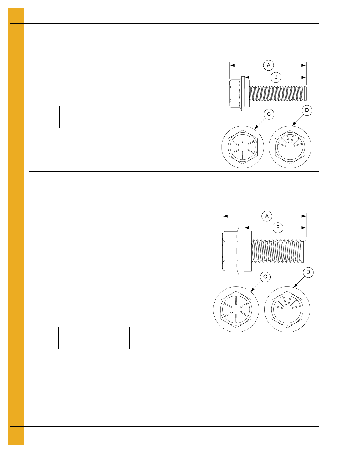
Bolt (S-7485) is used in the following locations:
1. Use to splice the stiffeners together on the flanges.
(A flange nut is used on the nut side of the connection.)
2. Use to splice the laminated stiffeners together. (A flange
nut is used on the nut side of the connection.)
3. The color of bucket lid is light green.
A 1.350" (3.43 cm) C Grade 8
B 1.000" (2.54 cm)
D Grade 8.2
Bolt (S-7488) is used in the following locations:
1. Use in all stiffener to sidewall and overlap connections
where the sidewall is 9 gauge or thicker.
2. Use in vertical and horizontal seams on sidewall that is
6 gauge or thicker.
3. The color of the bucket lid is orange.
NOTE: Do not use in flanges where the splice plate bolts
to the stiffeners. Sealing washers should not be
used for these connections.
A 1.850" (4.70 cm) C Grade 8
B 1.500" (3.81 cm)
D Grade 8.2
Bolt (S-7485)
An S-7485 is a 3/8" x 1" JS hex bolt with flanged head and without a sealing washer.
Bolt (S-7488)
An S-7488 is a 3/8" x 1-1/2" JS bolt that is pre-assembled with a sealing washer.
PNEG-4042 40 Series 42' and 48' Diameter Bins 27
Page 28
4. Bolt and Nut Usage
Bolt (S-7486) is used in the following locations:
1. Use in special seismic tanks.
2. The color of the bucket lid is dark brown.
A 1.850" (4.70 cm)
B 1.500" (3.81 cm)
C Grade 8
DGrade 8.2
Bolt (S-10250) is used in the following locations:
1. Use in bins 54' and 60' in diameter.
2. Use in eave bracket to inside stiffener connection.
3. Use in tension plate to eave bracket connection.
4. Use in rafter clip to rafter connection.
5. Use in laminated purlins.
6. Use in purlin clip to rafter and purlin clip to purlin
connections.
7. Use in X-brace to rafter connection.
8. Use in center collar splice connection.
9. Use in center collar channel clip to center collar.
10. Use in rafter to center collar and rafter to eave bracket
connections.
11. Use in center collar channel to clip.
12. Delivered in a box, not a bucket.
A 1.542" (3.92 cm) C Grade 8
B 1.250" (3.18 cm)
D Grade 8.2
Bolt (S-7486)
An S-7486 is a 3/8" x 1-1/2" JS hex bolt with a flanged head without a sealing washer.
Bolt (S-10250)
An S-10250 is a 7/16" x 1-1/4" JS bolt that is pre-assembled with a sealing washer.
28 PNEG-4042 40 Series 42' and 48' Diameter Bins
Page 29
4. Bolt and Nut Usage
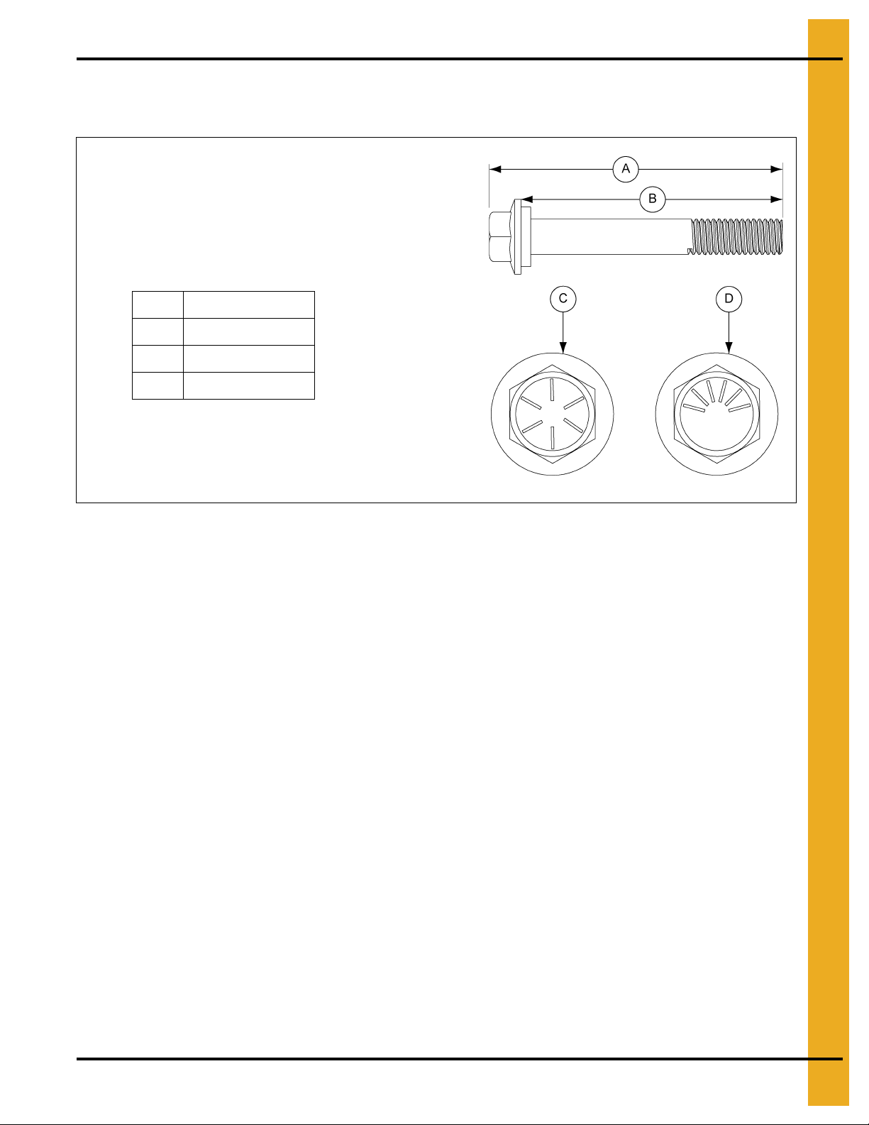
Bolt (S-10261) is used in the following locations:
1. Use in wind ring splice and over pipe connections.
2. Lid color of bucket is natural (clear).
A 3.645" (9.26 cm)
B 3.250" (8.26 cm)
C Grade 8
D Grade 8.2
Bolt (S-10261)
An S-10261 is a 7/16" x 3-1/4" JS bolt that is pre-assembled with a sealing washer.
PNEG-4042 40 Series 42' and 48' Diameter Bins 29
Page 30
4. Bolt and Nut Usage
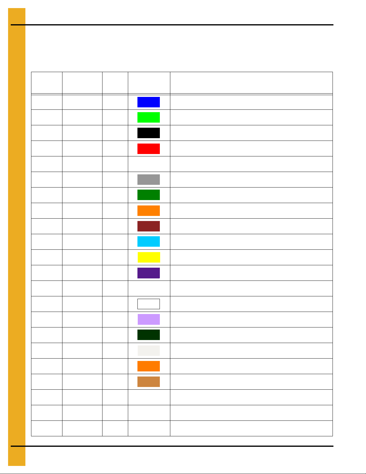
Color Chart for Bin Hardware Bucket Lids
For ease of identification, hardware is separated and identified by buckets with color coded lids. Use the
following chart to help with the correct placement of hardware.
Part # Color
S-275 Dark Blue 1500 5/16" x 3/4" YDP Bolt pre-assembled with sealing washer
S-10260 Lime Green 1250 5/16" x 1" YDP Bolt pre-assembled with sealing washer
S-277 Black 1000 5/16" x 1-1/4" JS Bolt pre-assembled with sealing washer
S-396 Red 5000 5/16" JS Hex nut
S-3611 NA NA In Box 5/16" YDP Flange nut
S-7487 Grey 850 3/8" x 1" JS Bolt pre-assembled with sealing washer
S-7485 Light Green 1000 3/8" x 1" Flanged JS bolt without sealing wash er
S-7488 Orange 650 3/8" x 1-1/2" JS Bolt pre-assembled with sealing washer
S-7486 Dark Brown 700 3/8" x 1-1/2" Flanged JS bolt without sealing washer
S-10165 Light Blue 500 3/8" x 2" JS Bolt pre-assembled with sealing washer
Bucket
Count
Lid Color Description
S-7489 Yellow 4000 3/8" JS Hex nut
S-9426 Dark Purple 2500 3/8" JS Flanged nut
S-10250 NA NA In Box 7/16" x 1-1/4" YDP Flanged bolt
S-10262 White 500 7/16" x 1-1/2" Flanged JS bolt pre-assembled with sealing washer
S-9389 Light Purple 350 7/16" x 2" Full threaded JS bolt pre-assembled with sealing washer
S-10134 Dark Green 300 7/16" x 2-1/2" JS Bolt pre-assembled with sealing washer
S-10261 Natural (Clear) 200 7/16" x 3-1/4" Flanged JS bolt pre-assembled with sealing washer
S-9281 Fire Orange 1500 7/16" JS Hex nut
S-8479 Light Brown 800 7/16" YDP Special recessed nut
S-10251 NA NA In Box 7/16" YDP Un-serrated flange nut
S-10252 NA NA In Box 1/2" x 1-3/4" YDP Flange bolt
S-10253 NA NA In Box 1/2" YDP Un-serrated flange nut
30 PNEG-4042 40 Series 42' and 48' Diameter Bins
Page 31

5. Assembling Sidewall Sheets
Color Codes for Sidewall Gauge Identification
Use this chart to interpret the color code painted on the corners of the sidewall sheets.
Color Codes for Sidewall Gauges
Sidewall Gauge Color Code
20 Red
19 Black and Yellow
18 Orange
17 Light Blue and Pink
16 Blue
15 Red and Brown
14 Green
13 Dark Blue and Yellow
12 Black
11 Pink
10 Light Blue
9 Dark Blue and Orange
Stripe Colors for Special Sidewall Characteristics
Type of Sidewall Stripe Color
BFT Blue
Laminated Gold
Hex Pattern Ochre
Special Galvanized 115 Fluorescent Red and Orange
Special Galvanized 140 Fluorescent Pink
Special Galvanized 160 Fluorescent Red and Pink
NOTE: Stripe colors are located in the middle of each
side of the bundle.
8 Yellow
6White
5 Fluorescent Green
PNEG-4042 40 Series 42' and 48' Diameter Bins 31
Page 32

5. Assembling Sidewall Sheets
Caulking Detail for Standard (Non-Laminated) Sheets
To keep out moisture from overlapping the sheets, it is necessary to apply caulk to each sheet prior
to installing.
NOTE: Always assemble the sidewall sheets with the overlap in the same direction.
1. Apply a strip of caulk near the outside edge of the outer sheet and between the outer two (2) rows
of bolts (A), then apply a strip of caulk 10" (25.4 cm) long along the horizontal se ams (B), as shown
in Figure 5A.
Figure 5A Standar d and Quad Punched Sidewall Sheets as Viewed from the Out side
Ref # Description
A Vertical Strip of Caulk
B 10" (25.4 cm) Horizontal Strip of Caulk
2. Before bolting the next ring into place, apply one 10" strip of caulk (C) on the front of the underlapped
sheet at each joint.
3. Also, place a 10" (25.4 cm) strip of caulk (D) along the lower horizontal edge of the lapping
sheet at every vertical seam. This will fill the space that occurs between the holes caused by the
overlapping sheets. (See Figure 5B on Page 33.)
32 PNEG-4042 40 Series 42' and 48' Diameter Bins
Page 33

5. Assembling Sidewall Sheets
Figure 5B Caulking Detail as Viewed from Inside of the Bin
Ref # Description
C 10" (25.4 cm) Strip of Caulk
D 10" (25.4 cm) Strip of Caulk
4. Use the supplied tube caulk to fill the larger gaps that occur with heavier gauges and laminated
gauges. See Caulking Detail for Laminated Quad Pattern Sheets on Page 34 for details ab out caulk
laminated sidewall sheets.
PNEG-4042 40 Series 42' and 48' Diameter Bins 33
Page 34

5. Assembling Sidewall Sheets
Caulking Detail for Laminated Quad Pattern Sheets
To keep out moisture from overlapping the sheets, it is necessary to apply caulk to each sheet prior
to installing.
Caulking and Assembling the Individual Sidewall Sheets
Each sidewall sheet must be layered and caulked prior to assembling sidewall sheet seams together.
Figure 5C Laminated Quad Punched Sidewall Panel View from Outside of the Bin
Ref # Description
A Strip of Caul ki n g
B 12" (30.4 cm) Horizontal Strip of Caulking
34 PNEG-4042 40 Series 42' and 48' Diameter Bins
Page 35

5. Assembling Sidewall Sheets
Figure 5D Laminated Figurate Punched Sidewall Sheets View from Outside of the Bin
Ref # Description
A Strip of Caulking
B 12" (30.4 cm) Horizontal Strip of Caulking
Figure 5E Caulking Between Laminated Figurate Pattern Sheets
Ref # Description
B 12" (30.4 cm) Horizontal Strip of Caulking
PNEG-4042 40 Series 42' and 48' Diameter Bins 35
Page 36

5. Assembling Sidewall Sheets
1. When assembling two (2) assembled laminated sheets to each other, apply a strip of caulk (A) near
the outside edge of the outer sheet, between the outer two (2) rows o f bolts and outside the last ro w
of bolts. (See Figure 5C on Page 34 and Figure 5D on Page 35.)
2. Place a strip of caulk (B) 12" (30.4 cm) long to each the horizontal seams. (See Figure 5F.)
NOTE: Before bolting the next ring into place, apply a strip of caulk 12" (30.4 cm) long on the front
of the under lapped sheet at each joint.
3. Also, a 12" (30.4 cm) strip of caulk is to be placed along the lower horizontal edge of the lapping
sheet at the vertical seam. This will fill the space that occurs between the holes caused by the
overlapping sheets.
When assembling two (2) sheets to make a laminated sheet assembly (C), apply a row of caulk all around
the vertical seam. (See Figure 5F.)
Use the supplied tube caulk to fill the larger gaps that occur with heavier gauges and laminated sheets.
Figure 5F Caulking Detail for Assembled Laminate Sidewall Sheets
Ref # Description
B 12" (30.4 cm) Horizontal Strip of Caulk
C Laminated Sheet Detail (Caulk Not Shown)
36 PNEG-4042 40 Series 42' and 48' Diameter Bins
Page 37

6. Stiffeners
Stiffener Part Number Description
Part numbers are printed on the end of each stiffener with the last two (2) numbers designating the gauge
of the material.
Example: CTS-206314 will be printed on a 14 gauge, standard 2 ring stiffener. If the stiffener was 8 gauge,
it would change the part number to CTS-206308.
The part numbers in the following tables use an “XX” at the end of the number to represent the gauge of
the material.
Color Codes for Stiffener Gauge Identification
Use these charts to interpret the color code painted on the ends of the stiffeners.
Color Codes for Stiffener Gauges
Sidewall Gauge Color Code
0 No Color (Zinc)
2Ochre
5 Fluorescent Green
6White
8 Yellow
9 Dark Blue and Orange
10 Light Blue
11 Pink
12 Black
13 Dark Blue and Yellow
14 Dark Green
15 Red and Brown
Stripe Color Codes for Stiffener Gauges
Stiffener Type Stripe Color
Base Stiffener Red
Back (Laminated) Dark Green
Insert (Laminated) Gold
Close Punched Light Blue
Special Galvanized 115 Fluorescent Red and Orange
Special Galvanized 140 Fluorescent Pink
Special Galvanized 165
12 Bolt Pattern Stiffener Brown
NOTE: Extra colored stripes will be centered on the
gauge color. If more than one color of stripe is needed,
they will be painted next to each other and centered
on the gauge color.
Fluorescent Pink and
Fluorescent Orange
16 Dark Blue
17 Light Blue and Pink
18 Orange
PNEG-4042 40 Series 42' and 48' Diameter Bins 37
Page 38

6. Stiffeners
Standard Stiffeners
Use the following information to determine the differences between the types of standard 2 ring stiffeners.
(See Figure 6A.)
Figure 6A Standard Stiffeners
Ref # Part # Description Length Available Gauges
A CTS-2063XX 2 Ring Stiffener 63.938" (162 cm) 10-14
B CTS-2064XX 2 Ring Stiffener 63.938" (162 cm) 15-16
C CTS-2073XX 2 Ring Stiffener (Close-Punch) 63.938" (162 cm) 2-10, 12, 14
D CTS-2075XX 2 Ring Stiffener (Close-Punch) 63.938" (162 cm) 16
E CTS-2079XX 2 Ring Laminated Stiffener (Close-Punch) 63.938" (162 cm) 2-5
F CTS-208 1XX 2 Ring Insert (Close-Punch) 63.938" (162 cm) 10-14
G CTS-2137XX 2 Ring Laminate Stiffener (Close-Punch) 63.938" (162 cm) 2
H CTS-2138XX 2 Ring Insert (Close-Punch) 63.938" (162 cm) 2-14
38 PNEG-4042 40 Series 42' and 48' Diameter Bins
Page 39

6. Stiffeners
Top Stiffeners
Use the following information to determine the differences between the three (3) types of top stiffeners.
(See Figure 6B.)
Figure 6B Images of the To p Stiffeners
Ref # Part # Description Length Available Gauges
A CTS-2069XX Inside Stiffener (for Roof) 23.938" (56 cm) 2-8, 10, 12, 14
B CTS-2118XX 1 Ring Top Stiffener (Close-Punch) 21.938" (56 cm) 16
C CTS-2111XX 2 Ring Top Stiffener 53.938" (137 cm) 15-16
D CTS-2116XX 2 Ring Top Stiffener (Close-Punch) 53.938" (137 cm) 16
PNEG-4042 40 Series 42' and 48' Diameter Bins 39
Page 40

6. Stiffeners
Stiffeners Splice
Use the following information to determine the gauge of the splice needed to connect the stiffeners.
(See Figure 6C.)
Figure 6C Stiffener Splice
Ref # Part # Description Length Available Gauges
A CTS–2091XX Stiffener Splice 10" (25.4 cm) 8, 10, 12, 14
Use the following chart to determine the gauge of the splice, which is determined by the gauge of the
stiffeners that are being connected. If connecting a heavier gauge to a lighter gauge stiffener, always use
the heavier gauge splice for the 13 to 12, 8 to 6 and 2 to 0 gauge connections.
For example: If connecting a 13 gauge stiffener to a 12 gauge stiffener, use the 12 gauge splice. If
connecting an 8 gauge stiffener to a 6 gauge stiffener, use the 10 gauge splice. If connecting a 2 gauge
stiffener to a 0 gauge stiffener, use the 8 gauge splice.
Splice Usage
Stiffener Gauge
8 Gauge 10 Gauge 12 Gauge 14 Gauge
18 X
17 X
16 X
15 X
14 X
13 X
12 X
11 X
10 X
9X
8 X
Splice Gauge
6X
5 X
2X
0 X
40 PNEG-4042 40 Series 42' and 48' Diameter Bins
Page 41

6. Stiffeners
Base Stiffeners
Use the following information to determine the differences between the base stiffeners. (See Figure 6D.)
Figure 6D Images of the Base Stiffeners
Ref # Part # Description Length Available Gauges
A CTS-21 19XX Base Stiffener 72.094" (183 cm) 2-8
B CTS-2123XX Base Stiffener 72.430" (184 cm) 9, 10, 12, 14, 16
C CTS-2115XX Base Stiffener 72.094" (183 cm) 10, 12, 14, 16
D CTS-2114XX Laminated Base Stiffener 72.061" (183 cm) 2-5
E CTS-21 13XX Base Insert 66.438" (169 cm) 2-8, 10, 12, 14
F CTS-21 33XX Laminated Base Stiffener 72.088" (183 cm) 2
G CTS-2134XX Base Insert 71.775" (182 cm) 10, 12, 14
H CTS-2135XX Laminated Base Stiffener 71.775" (182 cm) 2
I CTS-2136XX Base Insert 71.775" (182 cm) 2-8
PNEG-4042 40 Series 42' and 48' Diameter Bins 41
Page 42

6. Stiffeners
Base Boots
Use the following information to determine the differences between the base boots. (See Figure 6E.)
Figure 6E Images of the Base Boots
Ref # Part # Description Height Base Plate Size
A CTS–2121XX
B CTS-2110XX
C CTS-2109XX
D CTS-2131XX
Base Boot Weldment for 16 Through
9 Gauge Base Stiffeners
Base Boot Weldment for 8 Through a
Laminated 2 Gauge with an 11 Gauge Insert
Base Boot for 2 Gauge Laminated Base
Stiffeners with Inserts from 10 Through 2 Gauges
Base boot Weldment for 2+8 to
2+2 Base Stiffeners
1 1.391" (29 cm)
1 1.391" (29 cm)
1 1.391" (29 cm)
1 1.391" (29 cm)
6" x 9" x 3/8"
(15 cm x 23 cm x 0.95 cm)
6" x 9" x 3/4"
(15 cm x 23 cm x 1.90 cm)
8" x 10" x 3/4"
(20 cm x 25 cm x 1.90 cm)
8" x 10" x 1-1/2"
(20 cm x 25 cm x 3.81 cm)
42 PNEG-4042 40 Series 42' and 48' Diameter Bins
Page 43

6. Stiffeners
Close-Punch Connection for a 1 Ring Top Stiffener (16 Gauge) and
a 2 Ring Stiffener (16 Gauge)
Refer to the following information for a close-punch connection of a 1 ring top stiffener (CTS-2118XX) to
a 2 ring stiffener (CTS-2075XX). (See Figure 6F.)
Figure 6F 1 Ring Top Stiffener (16 Gauge) and a 2 Ring Stiffener (16 Gauge) Close-Punch Connection
Ref # Part # Description
A CTS-2118XX 1 Ring Top Stiffener
B CTS-2075XX 2 Ring Stiffener
C CTS-2091XX Splice
D S-7485 Flange Bolt 3/8"-16 x 1" JS Grade 8 or Grade 8.2
E S-9426 Flange Nut 3/8"-16 JS
F Completed Assembly
NOTE: 2 Post stiffeners shown. The bolt pattern will vary for 3 post. Only place bolts where holes in the
stiffeners align with holes in the sidewall sheet.
PNEG-4042 40 Series 42' and 48' Diameter Bins 43
Page 44

6. Stiffeners
2 Ring Top Stiffener to a 2 Ring Stiffener (15-16 Gauge) Connection
Refer to the following information when connecting a 2 ring top stiffener (CTS-2111XX) to a 2 ring stiffener
(CTS-2064XX). (See Figure 6G.)
Figure 6G 2 Ring Top Stiffener to a 2 Ring Stiffener (15-16 Gauge) Connection
Ref # Part # Description
A CTS-2111XX 2 Ring Top Stiffener
B CTS-2064XX 2 Ring Stiffener
C CTS-2091XX Splice
D S-7485 Flange Bolt 3/8"-16 x 1" JS Grade 8 or Grade 8.2
E S-9426 Flange Nut 3/8"-16 JS
F Completed Assembly
NOTE: 2 Post stiffeners shown. The bolt pattern will vary for 3 post. Only place bolts where holes in the
stiffeners align with holes in the sidewall sheet.
44 PNEG-4042 40 Series 42' and 48' Diameter Bins
Page 45

6. Stiffeners
Close-Punch Connection for a 2 Ring Top Stiffener to a 2 Ring
Stiffener (16 Gauge)
Refer to the following information for a close-punch connection of a 2 ring top stiffener (CTS-2116XX) to
a 2 ring stiffener (CTS-2075XX). (See Figure 6H.)
Figure 6H 2 Ring Top Stiffener to a 2 Ring Stiffener (16 Gauge) Close-Punch Connection
Ref # Part # Description
A CTS-2116XX 2 Ring Top Stiffener
B CTS-2075XX 2 Ring Stiffener
C CTS-2091XX Splice
D S-7485 Flange Bolt 3/8"-16 x 1" JS Grade 8 or Grade 8.2
E S-9426 Flange Nut 3/8"-16 JS
F Completed Assembly
NOTE: 2 Post stiffeners shown. The bolt pattern will vary for 3 post. Only place bolts where holes in the
stiffeners align with holes in the sidewall sheet.
PNEG-4042 40 Series 42' and 48' Diameter Bins 45
Page 46

6. Stiffeners
2 Ring Stiffener (15-16 Gauge) to a 2 Ring Stiffener (15-16 Gauge)
Connection
Refer to the following information when connecting a 2 ring stiffener (CTS-2064XX) to a 2 ring stiffener
(CTS-2064XX). (See Figure 6I.)
Figure 6I 2 Ring Stiffener (15-16 Gauge) to a 2 Ring Stiffener (15-16 Gauge) Connection
Ref # Part # Description
A CTS-2064XX 2 Ring Stiffener
B CTS-2064XX 2 Ring Stiffener
C CTS-2091XX Splice
D S-7485 Flange Bolt 3/8"-16 x 1" JS Grade 8 or Grade 8.2
E S-9426 Flange Nut 3/8"-16 JS
F Completed Assembly
NOTE: 2 Post stiffeners shown. The bolt pattern will vary for 3 post. Only place bolts where holes in the
stiffeners align with holes in the sidewall sheet.
46 PNEG-4042 40 Series 42' and 48' Diameter Bins
Page 47

6. Stiffeners
Close-Punch Connection for a 2 Ring Stiffener (16 Gauge) to a
2 Ring Stiffener (16 Gauge)
Refer to the following information for a close-punch connection of a 2 ring stiffener (CTS-2075XX) to a
2 ring stiffener (CTS-2075XX). (See Figure 6J.)
Figure 6J 2 Ring Stiffener (16 Gauge) to a 2 Ring Stiffener (16 Gauge) Close-Punch Connection
Ref # Part # Description
A CTS-2075XX 2 Ring Stiffener
B CTS-2075XX 2 Ring Stiffener
C CTS-2091XX Splice
D S-7485 Flange Bolt 3/8"-16 x 1" JS Grade 8 or Grade 8.2
E S-9426 Flange Nut 3/8"-16 JS
F Completed Assembly
NOTE: 2 Post stiffeners shown. The bolt pattern will vary for 3 post. Only place bolts where holes in the
stiffeners align with holes in the sidewall sheet.
PNEG-4042 40 Series 42' and 48' Diameter Bins 47
Page 48

6. Stiffeners
2 Ring Stiffener (0-14 Gauge) to a 2 Ring Stiffener (0-14 Gauge)
Connection
Refer to the following information when connecting a 2 ring stiffener (CTS-2063XX) to a 2 ring stiffener
(CTS-2063XX). (See Figure 6K.)
Figure 6K 2 Ring Stiffener (0-14 Gauge) to a 2 Ring Stiffener (0-14 Gauge) Connection
Ref # Part # Description
A CTS-2063XX 2 Ring Stiffener
B CTS-2063XX 2 Ring Stiffener
C CTS-2091XX Splice
D S-7485 Flange Bolt 3/8"-16 x 1" JS Grade 8 or Grade 8.2
E S-9426 Flange Nut 3/8"-16 JS
F Completed Assembly
NOTE: 2 Post stiffeners shown. The bolt pattern will vary for 3 post. Only place bolts where holes in the
stiffeners align with holes in the sidewall sheet.
48 PNEG-4042 40 Series 42' and 48' Diameter Bins
Page 49

6. Stiffeners
Close-Punch Connection for a 2 Ring Stiffener (0-14 Gauge) to a
2 Ring Stiffener (0-14 Gauge)
Refer to the following information for a close-punch connection of a 2 ring stiffener (CTS-2073XX) to a
2 ring stiffener (CTS-2073XX). (See Figure 6L.)
Figure 6L 2 Ring Stiffener (0-14 Gauge) to a 2 Ring Stiffener (0-14 Gauge) Close-Punch Connection
Ref # Part # Description
A CTS-2073XX 2 Ring Stiffener
B CTS-2073XX 2 Ring Stiffener
C CTS-2091XX Splice
D S-7485 Flange Bolt 3/8"-16 x 1" JS Grade 8 or Grade 8.2
E S-9426 Flange Nut 3/8"-16 JS
F Completed Assembly
NOTE: 2 Post stiffeners shown. The bolt pattern will vary for 3 post. Only place bolts where holes in the
stiffeners align with holes in the sidewall sheet.
PNEG-4042 40 Series 42' and 48' Diameter Bins 49
Page 50

6. Stiffeners
2 Ring Stiffener (0-14 Gauge) to a Close-Punch Base Stiffener
(2-8 Gauge) Connection
Refer to the following information when connecting a 2 ring stiffener (CTS-2063XX) to a close-punch
2 ring stiffener (CTS-2119XX). (See Figure 6M.)
Figure 6M 2 Ring Stiffener (0-14 Gauge) to a Close-Punch 2 Ring Stiffener (2-8 Gauge) Connection
Ref # Part # Description
A CTS-2063XX 2 Ring Stiffener
B CTS-2119XX Close-Punch 2 Ring Stiffener
C CTS-2091XX Splice
D S-7485 Flange Bolt 3/8"-16 x 1" JS Grade 8 or Grade 8.2
E S-9426 Flange Nut 3/8"-16 JS
F Completed Assembly
NOTE: 2 Post stiffeners shown. The bolt pattern will vary for 3 post. Only place bolts where holes in the
stiffeners align with holes in the sidewall sheet.
50 PNEG-4042 40 Series 42' and 48' Diameter Bins
Page 51

6. Stiffeners
Close-Punch Connection for a 2 Ring Stiffener (0-14 Gauge) to a
Base Stiffener (2-8 Gauge)
Refer to the following information when connecting a 2 ring stiffener (CTS-2073XX) to a base stiffener
(CTS-2119XX). (See Figure 6N.)
Figure 6N 2 Ring Stiffener (0-14 Gauge) to a 2 Ring Stiffener (2-8 Gauge) Close-Punch Connection
Ref # Part # Description
A CTS-2073XX Close-Punch 2 Ring Stiffener
B CTS-2119XX Close-Punch Base Stiffener
C CTS-2091XX Splice
D S-7485 Flange Bolt 3/8"-16 x 1" JS Grade 8 or Grade 8.2
E S-9426 Flange Nut 3/8"-16 JS
F Completed Assembly
NOTE: 2 Post stiffeners shown. The bolt pattern will vary for 3 Post. Only place bolts where holes in the
stiffeners align with holes in the sidewall sheet.
PNEG-4042 40 Series 42' and 48' Diameter Bins 51
Page 52

6. Stiffeners
2 Ring Stiffener (0-14 Gauge) to a Base Stiffener (10-16 Gauge)
Connection
Refer to the following information when connecting a 2 ring stiffener (CTS-2063XX) to a base stiffener
(CTS-2123XX). (See Figure 6O.)
Figure 6O 2 Ring Stiffener (0-14 Gauge) to a Base Stiffener (10-16 Gauge) Connection
Ref # Part # Description
A CTS-2063XX 2 Ring Stiffener
B CTS-2123XX Base Stiffener
C CTS-2091XX Splice
D S-7485 Flange Bolt 3/8"-16 x 1" JS Grade 8 or Grade 8.2
E S-9426 Flange Nut 3/8"-16 JS
F Completed Assembly
NOTE: 2 Post stiffeners shown. The bolt pattern will vary for 3 post. Only place bolts where holes in the
stiffeners align with holes in the sidewall sheet.
52 PNEG-4042 40 Series 42' and 48' Diameter Bins
Page 53

6. Stiffeners
2 Ring Stiffener (2-14 Gauge) to a Base Stiffener (10-16 Gauge)
Connection
Refer to the following information for a close-punch connection of a 2 ring stiffener (CTS-2073XX) to a
base stiffener (CTS-2115XX). (See Figure 6P.)
Figure 6P 2 Ring Stiffener (2-14 Gauge) to a Base Stiffener (10-16 Gauge) Close-Punch Connection
Ref # Part # Description
A CTS-2073XX Close-Punch 2 Ring Stiffener
B CTS-2115XX Close-Punch Base Stiffener
C CTS-2091XX Splice
D S-7485 Flange Bolt 3/8"-16 x 1" JS Grade 8 or Grade 8.2
E S-9426 Flange Nut 3/8"-16 JS
F Completed Assembly
NOTE: 2 Post stiffeners shown. The bolt pattern will vary for 3 post. Only place bolts where holes in the
stiffeners align with holes in the sidewall sheet.
PNEG-4042 40 Series 42' and 48' Diameter Bins 53
Page 54

6. Stiffeners
2 Ring Stiffener (15-16 Gauge) to a Base Stiffener (10-16 Gauge)
Connection
Refer to the following information when connecting a 2 ring stiffener (CTS-2064XX) to a base stiffener
(CTS-2123XX). (See Figure 6Q.)
Figure 6Q 2 Ring Stiffener (15-16 Gauge) to a Base Stiffener (10-16 Gauge) Connection
Ref # Part # Description
A CTS-2064XX 2 Ring Stiffener
B CTS-2123XX Base Stiffener
C CTS-2091XX Splice
D S-7485 Flange Bolt 3/8"-16 x 1" JS Grade 8 or Grade 8.2
E S-9426 Flange Nut 3/8"-16 JS
F Completed Assembly
NOTE: 2 Post stiffeners shown. The bolt pattern will vary for 3 post. Only place bolts where holes in the
stiffeners align with holes in the sidewall sheet.
54 PNEG-4042 40 Series 42' and 48' Diameter Bins
Page 55

6. Stiffeners
Close-Punch Connection for a 2 Ring Stiffener (16 Gauge) to a
Base Stiffener (10-16 Gauge)
Refer to the following information for a close-punch connection of a 2 ring stiffener (CTS-2075XX) to a
base stiffener (CTS-2115XX). (See Figure 6R.)
Figure 6R 2 Ring Stiffener (16 Gauge) to a Base Stiffener (10-16 Gauge) Close-Punch Connection
Ref # Part # Description
A CTS-2075XX Close-Punch 2 Ring Stiffener
B CTS-2115XX Close-Punch Base Stiffener
C CTS-2091XX Splice
D S-7485 Flange Bolt 3/8"-16 x 1" JS Grade 8 or Grade 8.2
E S-9426 Flange Nut 3/8"-16 JS
F Completed Assembly
NOTE: 2 Post stiffeners shown. The bolt pattern will vary for 3 post. Only place bolts where holes in the
stiffeners align with holes in the sidewall sheet.
PNEG-4042 40 Series 42' and 48' Diameter Bins 55
Page 56

6. Stiffeners
Close-Punch 2 Ring Stiffener (2-14 Gauge) to a Laminated Stiffener
(2 Gauge) with an Insert (10-14 Gauge)
Refer to the following information for a close-punch connections with a 2 ring stiffener (CTS-2073XX) to a
laminated stiffener (CTS-2114XX) and insert (CTS-2113XX). (See Figure 6S.)
Figure 6S Close-Punch 2 Ring Stiffener to a Laminated Stiffener with an Insert
Ref # Part # Description
A CTS-2073XX Close -Punch 2 Ring Stiffener
B CTS-2114XX Close-Punch Laminated Stiffener
C CTS-2113XX Insert
D S-7485 Flange Bolt 3/8"-16 x 1" JS Grade 8 or Grade 8.2
E S-9426 Flange Nut 3/8"-16 JS
F Completed Assembly
NOTE: 2 Post stiffeners shown. The bolt pattern will vary for 3 post. Only place bolts where holes in the
stiffeners align with holes in the sidewall sheet.
56 PNEG-4042 40 Series 42' and 48' Diameter Bins
Page 57

6. Stiffeners
Close-Punch Laminated Stiffeners (2 Gauge) with Inserts
(10-14 Gauge)
Refer to the following information for a close-punch connection of a laminated stiffen er (CTS-2079XX) to
a laminated stiffener (CTS-2081XX). (See Figure 6T.)
Figure 6T Close-Punch Laminated Stiffeners with Inserts
Ref # Part # Description
A CTS-2079XX Close-Punch Laminated Stiffener
B CTS-2081XX Close-Punch Insert
C S-7485 Flange Bolt 3/8"-16 x 1" JS Grade 8 or Grade 8.2
D S-9426 Flange Nut 3/8"-16 JS
E Completed Assembly
NOTE: 2 Post stiffeners shown. The bolt pattern will vary for 3 post. Only place bolts where holes in the
stiffeners align with holes in the sidewall sheet.
PNEG-4042 40 Series 42' and 48' Diameter Bins 57
Page 58

6. Stiffeners
Close-Punch Laminated Stiffener (2 Gauge) with an Insert
(10-14 Gauge) to a Laminated Base Stiffener (2-5 Gauge) with a
Base Insert (2-14 Gauge)
Refer to the following information for a close-punch connection of a 2 ring stiffener (CTS-2079XX and
CTS-2081XX) to a laminated base stiffener and insert (CTS-2114XX and CTS-2113XX). (See Figure 6U.)
Figure 6U Close-Punch Laminated Stiffener with an Insert to a Laminated Base Stiffener with a Base Insert
Ref # Part # Description
A CTS-2079XX Close-Punch Laminated Stiffener
B CTS-2081XX Close-Punch Insert
C CTS-2114XX Close-Punch Laminated Base Stiffener
D CTS-2113XX Close-Punch Base Insert
E S-7485 Flange Bolt 3/8"-16 x 1" JS Grade 8 or Grade 8.2
F S-9426 Flange Nut 3/8"-16 JS
G Completed Assembly
NOTE: 2 Post stiffeners shown. The bolt pattern will vary for 3 post. Only place bolts where holes in the
stiffeners align with holes in the sidewall sheet.
58 PNEG-4042 40 Series 42' and 48' Diameter Bins
Page 59

6. Stiffeners
Base Stiffener (10-16 Gauge) to a Base Boot Connection
Refer to the following information when connecting a base stiffener (CTS-2123XX) to a base boot
(CTS-2121XX). (See Figure 6V.)
Figure 6V Base Stiffener (10-16 Gauge) to a Base Boot Connection
Ref # Part # Description
A CTS-2123XX Base Stiffener
B CTS-2121XX Base Boot
C S-7485 Flange Bolt 3/8"-16 x 1" JS Grade 8 or Grade 8.2
D S-9426 Flange Nut 3/8"-16 JS
E Completed Assembly
NOTE: 2 Post stiffeners shown. The bolt pattern will vary for 3 post. Only place bolts where holes in the
stiffeners align with holes in the sidewall sheet.
PNEG-4042 40 Series 42' and 48' Diameter Bins 59
Page 60

6. Stiffeners
Close-Punch Connection for a Base Stiffener (10-16 Gauge) to a
Base Boot
Refer to the following information for a close-punch connection for a base stiffener (CTS-2115XX) to a
base boot (CTS-2121XX). (See Figure 6W.)
Figure 6W Base Stiffener (10-16 Ga uge) to a Base Boot Close-Punch Connection
Ref # Part # Description
A CTS-2115XX Close-Punch Base Stiffener
B CTS-2121XX Close-Punch Base Boot
C S-7485 Flange Bolt 3/8 "-16 x 1" JS Grade 8 or Grade 8.2
D S-9426 Flange Nut 3/8"-16 JS
E Completed Assembly
NOTE: 2 Post stiffeners shown. The bolt pattern will vary for 3 post. Only place bolts where holes in the
stiffeners align with holes in the sidewall sheet.
60 PNEG-4042 40 Series 42' and 48' Diameter Bins
Page 61

6. Stiffeners
Close-Punch Connection for a Base Stiffener (2+2 Gauge - 8 Gauge)
to a Base Boot
Refer to the following information for a close-punch connection for a base stiffener (CTS-2119XX) to a
base boot (CTS-2110XX). (See Figure 6X.)
Figure 6X Base Stiffener (2+2 Gauge - 8 Gauge) to a Base Boot Close-Punch Connection
Ref # Part # Description
A CTS-2119XX Close-Punch Base Stiffener
B CTS-2110XX Close-Punch Base Boot
C S-7485 Flange Bolt 3/8"-16 x 1" JS Grade 8 or Grade 8.2
D S-9426 Flange Nut 3/8"-16 JS
E Completed Assembly
NOTE: 2 Post stiffeners shown. The bolt pattern will vary for 3 post. Only place bolts where holes in the
stiffeners align with holes in the sidewall sheet.
PNEG-4042 40 Series 42' and 48' Diameter Bins 61
Page 62

6. Stiffeners
Close-Punch Laminated Base Stiffener (2 Gauge) with Insert
(2+14 to 2+10 Gauge) to a Base Boot
Refer to the following information when connecting a close-punch laminated base stiffener
(CTS-2114XX) to a base boot (CTS-2109XX or CTS-2110XX). (See Figure 6Y.)
Figure 6Y Close-Punch Laminated Base Stiffener to a Base Boot
Ref # Part # Description
A CTS-21 14XX Close-Punch Laminated Base Stiffener
B CTS-2113XX Close-Punch Base Insert
CTS-2109XX or
C
CTS-21 10XX
D S-7485 Flange Bolt 3/8"-16 x 1" JS Grade 8 or Grade 8.2
E S-9426 Flange Nut 3/8"-16 JS
F Completed Assembly
Close-Punch Base Boot
NOTE: 2 Post stiffeners shown. The bolt pattern will vary for 3 post. Only place bolts where holes in the
stiffeners align with holes in the sidewall sheet.
62 PNEG-4042 40 Series 42' and 48' Diameter Bins
Page 63

6. Stiffeners
Close-Punch Standard Stiffener to a 12 Bolt Pattern Laminated
Stiffener with Insert
Refer to the following information for a close-punch connection of a standard stiffener (CTS-2073) to a
12 bolt pattern laminated stiffener (CTS-2137XX) with insert (CTS-2138XX). (See Figure 6Z.)
Figure 6Z Close-Punch Standard Stiffener to a 12 Bolt Pattern Laminated Stiffener with Insert
Ref # Part # Description
A CTS-2073XX Close-Punch Standard Stiffener
B CTS-2137XX Close-Punch Laminated Stiffener
C CTS-2138XX Close-Punch Insert
D S-7485 F lange Bolt 3/8"-16 x 1" JS Grade 8 or Grade 8.2
E S-9426 Flange Nut 3/8"-16 JS
F Completed Assembly
NOTE: 2 Post stiffeners shown. The bolt pattern will vary for 3 post. Only place bolts where holes in the
stiffeners align with holes in the sidewall sheet.
PNEG-4042 40 Series 42' and 48' Diameter Bins 63
Page 64

6. Stiffeners
12 Bolt Pattern Close-Punch Laminated Stiffeners with Insert
Refer to the following information for a close-punch connection of two (2) 12 bolt pattern laminated
stiffeners (CTS-2137XX) with an inserts (CTS-2138XX). (See Figure 6AA.)
Figure 6AA Close-Punch 12 Bolt Pattern Laminated Stiffeners with Insert
Ref # Part # Description
A CTS-2137XX Close-Punch Laminated Stiffener
B CTS-2138XX Close-Punch Insert
C S-7485 Flange Bolt 3/8"-16 x 1" JS Grade 8 or Grade 8.2
D S-9426 Flange Nut 3/8"-16 JS
E Completed Assembly
NOTE: 2 Post stiffeners shown. The bolt pattern will vary for 3 post. Only place bolts where holes in the
stiffeners align with holes in the sidewall sheet.
64 PNEG-4042 40 Series 42' and 48' Diameter Bins
Page 65

6. Stiffeners
Close-Punch 12 Bolt Pattern Laminated Stiffener to Laminated
Base Stiffener with an Inserts to a Base Boot
Refer to the following information for a close-punch connection of a 12 bolt pattern laminated stiffener
(CTS-2137) to a laminated base stiffener (CTS-2135XX) with a inserts (CTS-2138XX and CTS-2135XX)
to a base boot (CTS-2131XX). (See Figure 6AB.)
Figure 6AB Laminated Stiffener to Laminated Base Stiffener with an Inserts to a Base Boot
Ref # Part # Description
A CTS-2137XX Close-Punch Laminated Stiffener
B CTS-2138XX Close-Punch Base Insert
C CTS-2135XX Close-Punch Laminated Base Stiffener
D CTS-2136XX Close-Punch Base Insert
E CTS-2131XX Base Boot
F S-7485 Flange Bolt 3/8"-16 x 1" JS Grade 8 or Grade 8.2
G S-9426 Flange Nut 3/8"-16 JS
H Completed Assembly
NOTE: 2 Post stiffeners shown. The bolt pattern will vary for 3 post. Only place bolts where holes in the
stiffeners align with holes in the sidewall sheet.
PNEG-4042 40 Series 42' and 48' Diameter Bins 65
Page 66

6. Stiffeners
Close-Punch 12 Bolt Pattern Laminated Stiffener to Laminated
Base Stiffener with an Inserts to a Base Boot
Refer to the following information for a close-punch connection of a 12 bolt pattern laminated stiffener
(CTS-2137) to a laminated base stiffener (CTS-2133XX) with a inserts (CTS-2138XX and CTS-2134XX)
to a base boot (CTS-2109XX or CTS-2110XX). (See Figure 6AC.)
Figure 6AC Laminated Stiffener to Laminated Base Stiffener with an Inserts to a Base Boot
Ref # Part # Description
A CTS-2137 Close-Punch Laminated Stiffener
B CTS-2138XX Close-Punch Base Insert
C CTS-2133XX Close-Punch Laminated Base Stiffener
D CTS-2134XX Close-Punch Base Insert
CTS-2109XX or
E
CTS-2110XX
F S-7485 Flange Bolt 3/8"-16 x 1" JS Grade 8 or Grade 8.2
G S-9426 Flange Nut 3/8"-16 JS
H Completed Assembly
Base Boot
NOTE: 2 Post stiffeners shown. The bolt pattern will vary for 3 post. Only place bolts where holes in the
stiffeners align with holes in the sidewall sheet.
66 PNEG-4042 40 Series 42' and 48' Diameter Bins
Page 67

7. Base Angle Installation
Installing the Base Angle
Installing the base angle ring will help reinforce and seal the final ring.
What You Should Know
The base angle overlap should be offset two (2) holes from the stiffener. Do not place overlap in line with
the stiffener.
1. Place a section of the base angle (B) to the bottom portion of the final ring (A).
NOTE: The sidewall sheet will sit on top of the base ang le with the vertical po rtion of the base angle
on the inside of the bin. And each end of the base angle will connect to the next base
angle section.
2. Install bolts (C) and nuts (D) as shown, but leaving the end holes of each section unfilled until the
next section is to be installed.
3. Attach the next base angle section overlapping the end holes (E) and install bolts (C) and nuts (D).
4. Repeat this procedure for the remaining base angle sections (B) over lapping the previously installed
base angle section.
5. Before the bolts (C) are tightened, push the base angle tight against the bottom edge of each sheet.
6. Tighten the hardware to the recommended torque specifications, see bolt torque specifications
on Page 24.
7. Before lowering the bin, apply the optional mastic sealer strip (F) to the entire underneath side of the
base angle.
NOTE: If optional mastic sealer strip is not used, it is recommended that some other met hod should
be utilized to seal the base ring to the concrete.
8. Lower the bin onto the foundation and check for an adequate seal. (See Figure 7A.)
Figure 7A Exploded View of Base Angle (View from inside the bin.)
PNEG-4042 40 Series 42' and 48' Diameter Bins 67
Page 68

7. Base Angle Installation
Ref # Part # Description
A Final Ring Assembly
B B-6753 Base Angle
C S-7487 Flange Bolt 3/8"-16 x 1" JS Grade 8 or Grade 8.2
D S-9426 Flange Nut 3/8"-16 JS
E Base Angle Offset Example
F Optional Mastic Sealer (or Equivalent)
Anchor Bolt Detail
The following is the minimum requirement for anchorage on standard tanks. Refer to sidedraw instructions
for special anchorage details.
1. 3/4" Diameter anchor bolt (A) is the minimum allowed.
2. Exposed anchor bolt thread height (B), 3" (7.62 cm).
3. Overall anchor bolt length (C), 18" (45.72 cm).
4. Hook length (D), 4-3/4" (12.065 cm). (See Figure 7B.)
Figure 7B Anchor Bolt Example (3/4" Diameter anchor bolt shown.)
Ref # Part # Description
A B-4161 3/4" Bolt Assembly Package
B Exposed Anchor Bolt Thread Height 3" (7.62 cm)
C Overall Anchor Bolt Length 18" (45.72 cm)
D Hook Length 4-3/4" (12.065 cm)
68 PNEG-4042 40 Series 42' and 48' Diameter Bins
Page 69

7. Base Angle Installation
Installing the Base Angle Shims
A section of the base boot plate will rest on top of the base angle, therefore causing the base boot to rest
unevenly on the foundation. To offset this, base angle shims are required to ensure the base boot sets
evenly on the foundation.
What You Should Know
1. Place the required base angle shim around the anchor bolt next to the base angle.
2. Place the base stiffener over the anchor bolt onto the required shim.
3. If needed, add standard shims under the required base angle shim. (See Figure 7C.)
NOTE: If more than one additional shim is required, then the shims must be welded together to the
base plate or the base plate must be grouted to provide the proper elevation.
Figure 7C Base Angle Shims
Ref # Part # Description
CTS-2121XX or
A
CTS-2110XX
B B-7027 Required Base Angle Shim for 6 x 9 Base Plate
C SS-6953 Standard Shim for 6 x 9 Base Plate
CTS-2109XX or
D
CTS-2131XX
E B-7028 Required Base Angle Shim for 8 x 10 Base Plate
F SS-7212 Standard Shim for 8 x 10 Base Plate
B-7025XX or
G
B-7026XX
PNEG-4042 40 Series 42' and 48' Diameter Bins 69
6 x 9 Base Plate
8 x 10 Base Plate
Base Angle
Page 70

7. Base Angle Installation
Anchor Bolt Washer Installation
Anchor bolt washers help to cover the oversized hole in the base plate.
Before You Begin
Anchor bolts are secured and base plates installed.
1. Place a square plate washer (B) onto the anchor bolt (A).
NOTE: A square plate washer (provided) must be installed between the base stiffener (C) and
washer (D).
2. Install a washer (D) and secure with a nut (E). (See Figure 7D.)
3. Tighten to the recommended torque specification, see bolt torque specifications on Page 24.
Figure 7D Base Stiffener Assembly
Ref # Part # Description
A B-4161 3/4" Bolt Assembly Package
B HT-635 Square Washer for 3/4" Anchor Bolt
B B-6756 Square Washer for 1" Anchor Bolt
C Base Stiffener
D S-866 Flat Washer 3/4" USS ZN Flat Grade 2
E S-234 Hex Nut 3/4"-10 ZN Grade 5
70 PNEG-4042 40 Series 42' and 48' Diameter Bins
Page 71

8. Instructions
Stirring devices may create additional loads on grain bin sidewalls, roofs and
floors. If high-moisture grain is loaded too deep and too fast, unstiffened bin
walls can become overloaded. Observe the following installation and operation
procedures if the bin is to be equipped with the stirring device.
WARNING
Instructions for Stirring Devices
Bins are offered in more than one structural series for specific uses. To maintain the warranty, the
appropriate “series” grain bin must be used. Consult the sales catalog or contact the Engineering
Department for current recommendations. Note that the use of any stirring device with three (3) or more
vertical screws may require a heavier than “standard” series bin. Any re-circulating device or system
should be used in the “re-circulating” series bins. NOTE: For GSI bins larger than 36' diameter an
alternate method of mounting is to attach suspension chain to intermediate center collar.
1. Read owner’s manual for the stirring device and follow all instructio ns set forth by the manufacturer.
IMPORTANT: Install the switch for the stirring device near the roof manway opening so that the
unit can be observed while stirring.
2. Make sure there are no obstructions, such as protruding ladders.
3. After loading approximately 3' of grain, run the unit one complete revolution to determine if it is
working properly.
4. If the unit is functioning properly, operate the stirring device continuously while filling and drying to
avoid compacted grain around the vertical screws.
5. If it becomes necessary to stop a stirring device using laterally moving screws, try to stop it with the
vertical screws nearest to the center of the bin, away from the sidewall. Should a device stop or stall
for any reason and remain inoperable for any length of time, the auger carriage should be supported
to the grain surface before restarting. The vertical auger should be turned by hand, with a pipe
wrench, before power is applied.
6. For best results, fill the bin to one-half of the final intended depth. Dry grain to 16% and continue
filling. Use filling rates specified by stirring device manufacturer. If necessary to fill to the top without
stopping, reduce the filling rate and drying air temperature so that the stirring rate can kee p up with
the drying rate.
7. Do not overfill bin. Filling should be stopped at bottom of top ring or 30" below the track.
8. The preceding steps are only general instructions which apply to the majority of stirring devices.
Since there are different manufacturers of these devices, it is important to read the operator’s manual
thoroughly for specific instructions applicable to the machine.
PNEG-4042 40 Series 42' and 48' Diameter Bins 71
Page 72

8. Instructions
Auto-Vent Assembly and Installation Instructions
The following instructions are for assembling and installing the Auto-Vent. First, check the packing list to
ensure all components have been shipped. The unit is easiest assembled in the upside down position
as shown in the instructions.
Assembly
1. Take all parts out of the shipping box and check if all parts are present.
2. Turn one roof vent housing (MIS-6778) upside down. (See Figure 8A.)
3. Insert 5/16" x 1-1/4" bin bolt with neoprene washer through hole in the side of roof vent. Place
jamb nut onto the bolt and tighten. (See Figure 8A.)
4. Slide flap assembly (MIS-6777) on to bolt. The bolt should slide through hole in the flap assembly
bracket. Install with curvature cupped upward and the brackets in the position as shown in Figure 8A.
5. Insert 5/16" x 1-1/4" bin bolt with neoprene washer through the other side of the roof vent, through
jamb nut and other flap assembly bracket. Tighten nut against vent housing side.
6. Apply a bead of tube caulking around three (3) housing sides of the roof vent where it meets the
hold-down angle.
7. Place hold-down angle (MIS-4404) on the assembled roof vent. The wide end of the hold-down angle
must face vent discharge. Once aligned, screw nine (9) #10 self-drilling (S-280) screws through the
roof housing and into the hold-down angle. (See Figure 8B on Page 73.)
Ref # Part # Description
A MIS-6777 Flap Assembly
B MIS-6778 Vent Housing Asse mb ly
C 5/16" x 1-1/4" Nut and Bolt
Figure 8A
72 PNEG-4042 40 Series 42' and 48' Diameter Bins
Page 73

Assembly (Continued)
8. Instructions
Ref # Part # Description
A MIS-4404 Hold-Down Angle
B Short Side Approximately 15-3/8"
C Long Side Approximately 15-7/8"
Figure 8B
Installation
8. If the roof sheet does not have a pre-punched hole for the roof vent, a hole mu st be cut. The cut hole
should match the roof vent. The hole’s inside edge should be approximately 15" from the eave.
(See Figure 8E on Page 74.)
9. Place the three (3) foam strips on roof sheet, as shown in Figure 8D on Page 74. Position roof
vent over foam strips and bolt down using 5/16" x 3/4" bin bolts and nuts. NOTE: See Figure 8E on
Page 74 for lower two (2) bolts of vent.
Figure 8C
PNEG-4042 40 Series 42' and 48' Diameter Bins 73
Page 74

8. Instructions
Installation (Continued)
Figure 8D
Ref # Part # Description
A MIS-6780 Top Strip
B MIS-6781 Side S trips
C Long Side Approximately 15-7/8"
D Short Side Approximately 15-3/8"
E Roof Eave
Figure 8E
Ref # Description Ref # Description
Foam Strips
A 5/16" x 3/4" Bolts and 5/16" Flan g e Nuts (12) D
B Caulk with Tube Caulking (Three (3) sides of vent housing.)
NOTE: Install bolts for these two (2) holes with the bolt head and
neoprene washer to the underneath side of the roof sheet and the
C
5/16" flange nut against the vent hold-down angle. Caulk holes.
Top (MIS-6780) (1)
Sides (MIS-6781) (2)
E Approximately 15" from Eave
74 PNEG-4042 40 Series 42' and 48' Diameter Bins
Page 75

8. Instructions
Wire Grill Guard Roof Vent Assembly and Installation Instructions
The following instructions are for assembling and installing the wire grill guard roof vent. Before beginning
assembly, check the packing list to ensure all components have been received. The unit is easiest
assembled in the upside down position as shown in Figure 8F. Locate the roof vent as shown in
Figure 8J on Page 77.
Assembly
1. Turn one roof vent housing (MIS-6778) upside down. (See Figure 8F.)
2. Insert 5/16" x 1-1/4" bin bolt with neoprene washer through the hole in the side of the roof vent.
Place jamb nut onto the bolt and tighten. (See Figure 8F.)
3. Slide one eyelet of grill guard onto the 5/16" bin bolt.
4. Insert 5/16" x 1-1/4" bin bolt with neoprene washer through the other side of the roof vent, through
jamb nut and other eyelet of grill guard. Tighten nut against vent housing side.
5. Apply a bead of tube caulking around the three (3) housing sides of the roof vent where it meets the
hold-down angle.
6. Place hold-down angle (MIS-4404) on the assembled roof vent. The wide end o f the hold-down angle
must face the vent discharge. Once aligned, screw nine (9) #10 self-drilling (S-280) screws through
the roof housing and into the hold-down angle. (See Figure 8G on Page 76.)
Ref # Part # Description
A MIS-6776 Grill Guard
B MIS-6778 Vent Housing Asse mb ly
C 5/16" x 1-1/4" Nut and Bolt
Figure 8F
PNEG-4042 40 Series 42' and 48' Diameter Bins 75
Page 76

8. Instructions
Assembly (Continued)
Ref # Part # Description
A MIS-4404 Hold-Down Angle
B Short Side Approximately 15-3/8"
C
D Long Side Approximately 15-7/8"
Figure 8G
Caulk with Tube Caulking
(Three (3) sides of vent housing.)
Installation
7. If the roof sheet does not have a pre-punched hole for the roof vent, a hole must be cut. Cut the hole
to match the roof vent. The inside edge of the hole should be approximately 15" from the eave.
(See Figure 8J on Page 77.)
8. Place the three (3) foam strips on roof sheet, as shown in Figure 8I on Page 77. Position roof
vent over foam strips and bolt down using 5/16" x 3/4" bin bolts and nuts. NOTE: See Figure 8J on
Page 77 for lower two (2) bolts of vent.
Figure 8H
76 PNEG-4042 40 Series 42' and 48' Diameter Bins
Page 77

Installation (Continued)
Figure 8I
8. Instructions
Ref # Part # Description
A MIS-6780 Top Strip
B MIS-6781 Side Strips
C Long Side Approximately 15-7/8"
D Short Side Approximately 15-3/8"
E Roof Eave
Figure 8J
Ref # Description Ref # Description
Foam Strips
A 5/16" x 3/4" Bolts and 5/16" Flan g e Nuts (12) D
B Caulk with Tube Caulking (Three (3) sides of vent housing.)
NOTE: Install bolts for these two (2) holes with the bolt head and
neoprene washer to the underneath side of the roof sheet and the
C
5/16" flange nut against the vent hold-down angle. Caulk holes.
Top (MIS-6780) (1)
Sides (MIS-6781) (2)
E Approximately 15" from Eave
PNEG-4042 40 Series 42' and 48' Diameter Bins 77
Page 78

9. Manway Cover Assembly
Round Manway Cover
Round manway cover detail for bins 60' and smaller.
Figure 9A
Ref # Part # Description Ref # Part # Description
A ACD-4505 Hinge Leaf H 5/16" Flange Nut
B ACD-4504 Manway Cover
C ACD-4513 Handle J ACD-4506 Hinge Base
D CRP-5003 Handle Gasket
E ACD-4514 Latch L 5/16 " x 3/4" Bolts
F CRP-4998 Manway Seal Strip
G Manway Roof Sheet
I CRP-4999 Moisture Diverter
K Double Nut these Bolt
Suffocation/Flighting Danger Decals
M
DC-GBC-1A
DC-GBC-1S
(Located Under Cover)
English
Spanish
Apply caulking to underneath side of moisture diverter to seal between the corrugated roof sheet and
diverter. Attach the moisture diverter and hinge base to manway roof sheet with 5/16" x 3/4" bolts and nuts.
Place hinge leaf on manway cover and bolt both hinge parts together with 3/8" x 1" bolts and lock nuts.
Attach the handle with two (2) #10-24 x 5/8" long bolts and #10-24 lock nuts. Slip a 5/16" nut in the latch
bar, thread on the shaft of handle and adjust latch bar so it will catch the bottom side of the manway sheet.
Snap the manway seal strip to the manway seal. (See Figure 9A.)
78 PNEG-4042 40 Series 42' and 48' Diameter Bins
Page 79

10. Center Collar Details
18', 24' through 54' Roofs
Color code: Red
21' Roof
Color code: Blue
Center Collar Details
The standard roof with a dome cap lid will have a center collar assembled from three (3) pieces.
The dome cap will mount onto it as well as the flashing. The dome cap is stan dard on all 18'-36' 40 Series
bins. A flat top is standard on all 42'-60' 40 Series bins.
For the 36' dome cap bins, this will be the upper or “top” center collar. The lower or “Z” center collar details
are given on the later pages.
36' and larger flattop bins do not have the top center collar.
PNEG-4042 40 Series 42' and 48' Diameter Bins 79
Figure 10A
Page 80

11. Roof Assembly
Roof Assembly
After completing the first sidewall ring, you are ready to begin construction. Begin with the center collar
sections. For convenience in opening and closing the center cover, the roof ladder and manhole sheet
should be placed directly opposite the two (2) slide rod holes in the center collar. Next build a roof center
support to hold the peak in place at the proper height. A simple structure composed of a sturdy cross
arm attached to a pole and supported by a platform or scaffolding will do. Stand the center support directly
in the center of the bin. The following dimensions are approximate distances used in bin roof construction.
Adjusting the center support height will ease roof erection. Place eave clips inside the bin wall to maintain
an opening around the top of the sidewall. This allows condensation, which normally collects on the
underneath side of the roof panels, to flow freely to the outside of the bin, thus avoiding possible
grain spoilage. (See Figure 11A.)
Use with 1 Ring of
Bin Diameter
42' 13'-10" 16'-6''
48' 15'-4" 18'-0"
2.66'' Corrugated Sidewall
“A” “A”
2.66'' Corrugated Sidewall
Use with 2 Ring of
Figure 11A
Ref # Description
A Bin Diameter
B Center Support Pole
80 PNEG-4042 40 Series 42' and 48' Diameter Bins
Page 81

11. Roof Assembly
NOTE: Use the same overlay procedure on all roof sheets.
For best results in erecting the roof, install two (2) roof panels in four (4) places as shown in Figure 11C.
When these eight (8) panels are in place, the peak assembly should be centered. Next add two (2) or
three (3) panels at a time to each section making certain to la p them the same way, until all panels are in
place. Be sure the panels are bolted loosely. DO NOT TIGHTEN BOLTS UNTIL THE ROOF IS
COMPLETELY ASSEMBLED. When installing the roof panels, take into consideration placing the
manway for ease of access to and from the sidewall and roof ladders. On Stiffened tanks, particularly
location of the manway panel and roof ladder in relation to the stiffeners is crucial for proper
installation of the ladder system. PNEG-1420 and PNEG-1738 for flat bottomed stiffened tanks.
These manuals are packaged with the ladder and safety cage packages.
Fasten roof sheets to eave clips and sidewall sheets as you assemble.
Figure 11C
Figure 11B Roof Overlay
Ref # Description
A Center Collar
B Roof Panels
PNEG-4042 40 Series 42' and 48' Diameter Bins 81
Page 82

12. Support Ring Instructions
WARNING
DO NOT OVERFILL BIN. Stored grain, although heaped in the center, should
be no higher than the roof eaves at the outer edge. Filling the bin above this
point creates excessive internal pressure and may cause swelling and eventual
failure of the roof.
Ring Instructions
Be sure to install ladder rungs and safety steps as you assemble roof panels. (See Figure 12A.) At this
point you will have completed assembly of the roof. Do not tighten bolts yet. Optional equipment and
accessories should now be installed.
NOTE: When assembling such pieces as roof ladder rungs, use 5/16" x 1" bolts with a flat washer on
top of the slot and extra neoprene washer between the roof and the piece being added. This will
ensure a more protective seal against moisture.
IMPORTANT: Maximum weight to be supported and/or suspended from the roof is to be 6000 pounds
for 18' through 36' (non-trussed) ONLY.
IMPORTANT: Maximum weight to be supported and/or suspended from the roof is 10000 lbs. for
commercial (trussed roof) 36'-60' flattop roof bins. Roof loads should be supported from
the flattop or at the second lower “Z” collar.
Figure 12A
Ref # Description
A Roof Steps
B Roof Channel
82 PNEG-4042 40 Series 42' and 48' Diameter Bins
Page 83

12. Support Ring Instructions
Roof Support Ring Instructions
Roof support rings are standard on all bins up to 48' diameter. Two (2) support rings are standard for 42'
and 48' diameter bins. All support rings will be placed on the outside of the roof panels.
To determine the location of the support rings, start at the narrow or peak of the roof panel and count
each hole. Having counted down the required distance, as described in the Chart below, install the
appropriate brackets. (T=Top, B=Bottom)
Expansion bolts should be fully contracted when assembling support rings. When you have completely
assembled both rings, (but prior to expanding the bolts) tighten all roof bolts including eave clip bolts.
Now extend expansion bolts by running the nut out on the threads. This procedure should be continued
evenly around the roof until the ring raises the roof to show a slight crown.
Support ring expansion bolts may become dislodged from the ring during high winds or when the inside
pressure of the bin is too great. If one expansion bolt is dislodged, the entire ring will become useless.
To prevent this, drill holes through the support ring and expansion bolt (after the rings have been installed
and expanded to the correct size) and insert a cotter pin or bolt through each hole.
NOTE: Welding of the expansion nuts to the pipe and expansion bolts or staking the expansion bolt
threads to prevent the movement of the jamb nut may be done as a n option to drilling and pinning.
Bin Diameter
Support Ring Location
42 (T)
42 (B)
48 (T)
48 (B)
See Page 85 for support ring placement on 42' and 48' roofs.
Support Ring Location
from Center
7th Hole
10th Hole
7th Hole
11th Hole
NOTE: Last support ring pipe must be cut to length.
Support Ring
Color Code
Fluorescent Green/Brown 8
Fluorescent Green/Gold 11
Fluorescent Green/Brown 8
Fluorescent Green/Pink 12
Number of Pipes
per Ring
PNEG-4042 40 Series 42' and 48' Diameter Bins 83
Page 84

12. Support Ring Instructions
Roof Support Ring Instructions (Continued)
Figure 12B
Ref # Part # Description Ref # Description
A R-997 Safety Ring Bracket C Expansion Bolt
B Support Ring D Omit Roof Step at Ring Locations
Support rings as shown on Page 85, are optional equipment. Support rings are optional for 54' diameter
tanks and 42'-48' tanks with a roof.
To determine the location of the safety rings, start at the narrow or peak of the roof panel and count each
hole separately. Count down the required distance and install the appropriate brackets. See Table on
Page 85 for proper location.
Expansion bolts should be fully contracted when assembling safety rings. When both rings are completely
assembled, but are not yet expanded, tighten all roof bolts including eave clip bolts. Now extend expansion
bolts by running nut out on threads. This procedure should be continued evenly around the roof until the
ring raises the roof to show a slight crown.
Safety Suggestion: Support ring expansion bolts may become dislodged from the ring d uring high winds
or when the inside pressure of the bin is too great. If one expansion bolt is dislodged, the entire ring will
become useless. To prevent this, drill holes through the support ring and expansion bolt (after the rings
have been installed and expanded to the correct size) and insert a cotter pin or bolt through each hole.
84 PNEG-4042 40 Series 42' and 48' Diameter Bins
Page 85

12. Support Ring Instructions
NOTE: Last support ring pipe
will need to be cut to length.
Roof Support Ring Instructions (Continued)
NOTE: Welding of expansion nuts to the pipe and expansion bolt may be done as an option to drilling
and pinning.
42'-48' Diameter Tanks
Bin Diameter
42'
48'
See Page 83 for roof ring placement.
Support Ring
Location from Center
8th Hole
9th Hole
Support Ring
Color Code
Black CRP-4752 CRP-4754 PLS-40233
Pink CRP-4753 CRP-4755 PLS-40234
Part #
Complete
Support Ring
Hardware
PNEG-4042 40 Series 42' and 48' Diameter Bins 85
Figure 12C
Ref # Part # Description
A R-997 Safety Ring Bracket
B Safety Ring (Optional)
C Expansion Bolt
Page 86

12. Support Ring Instructions
42' and 48' Roof Instructions
1. Begin roof construction after assembling the two (2) top sidewall rings. Be sure the sidewall rings
are round.
2. Attach the top stiffeners and a 1 ring stiffener as shown on Pages 87 and 88. The top stiffener bolts
should be left loose. The roof stiffener bracket fits inside the wall stiffeners.
3. Install the eave clips as shown on Page 91. Every third clip should be located at a roof stiffener.
NOTE: The eave clip bolt and nut must be reversed (bolt head on the inside) at the top stiffener
for clearance.
4. Roof trusses should be assembled into complete rafters for installation. This should include the roof
truss sections, roof splices, truss channel brackets and roof stiffener clips. Tighten all splice bolts with
trusses positioned to create a straight truss. (Straight truss assemblies with tight connections will
prevent possible problems in later construction.)
5. After placing the “Z” collar at the correct center height, begin installation of the truss assemblies.
Attach a roof truss assembly to a roof stiffener bracket with a partially tightened bolt. Raise the top
of the truss assembly and bolt to the “Z” collar using 5/16" x 1" bolts (do not tighten the bolts at this
time). Be sure to use 5/16" washers on the slots in the truss clip. Complete bolting to the roof stiffene r
bracket. The truss assembly must be stabilized at this point.
6. Place two (2) roof sheets on the truss assembly, one on each side of the rafter. The 5/16" x 1" bolts
in the “Z” collar must be removed and replaced through each roof sheet as they are positioned.
Use 5/16" x 1" bolts to connect the roof sheet ribs to the truss assembly. Be sure at least two (2)
5/16" x 1" bolts are placed in each roof sheet at the eave clip connections. These roof sheets will
stabilize the roof truss and center “Z” collar assembly.
7. Repeat Step 5 and Step 6 on the opposite side of the bin and then at the one quarter position
around the bin until four (4) rafter assemblies are erected with two (2) roof sheets each at four (4)
equally spaced positions.
8. Connect the remaining rafter assemblies. Truss channels should be installed with each additional
rafter assembly. Tighten the bolts on one end of the channel with the channel positioned as close as
possible to the roof rafter splice. This will stabilize the truss assembly and hold it in a vertical position.
Install the tension rods as shown in Page 91.
9. After completing the rafter system with all truss channels installed, the remaining roof sheets may be
bolted on the trusses. Be sure to install all roof ladder steps, intermediate eave clips and any other
necessary accessories.
10. Install the flattop as shown in Page 92. For bins with a dome cap option, the small center collar, roof
flashing and roof cap assembly can be installed as a complete unit. Be sure to tighten all connections
in the roof rafter system and related parts.
nd
11. Apply the peak load on the flattop on the second (2
), lower “Z” collar.
86 PNEG-4042 40 Series 42' and 48' Diameter Bins
Page 87

13. Roof Stiffener Location and Detail
For sidewall to stiffener connections, use 3/8" x 1" bin
bolt except horizontal seam. Stiffeners will bolt every 8".
NOTE: Splice plate and laminated stiffener to
sidewall connections, use 3/8" x 1-1/2" bin bolts.
Odd ring bins
Offset joints and 8 gauge splice plate joints, use 3/8" x 1" hex flanged head bolts. All other stiffener joints,
use 3/8" x 1-1/2" hex flanged head bolts. 3/8" Flange nuts used on all stiffener splice bolt connections.
Even ring bins
Three (3) Stiffeners per Sidewall Sheet Commercial Stiffener
Starting Location - 42' Diameter to 48' Diameter 2.66" Reverse
Corrugation Outside Stiffener Only
Figure 13A
Ref # Description
A Splice Plate
B 1 Ring Top Stiffener
C 2 Ring Top Stiffener
D Horizontal Seam
E 2 Ring Standard Stif fener
PNEG-4042 40 Series 42' and 48' Diameter Bins 87
Page 88

13. Roof Stiffener Location and Detail
NOTE: Insert corrugation spacer (S-7041) into corrugation.
42' through 48' Standard Roof Stiffener Detail 2.66" Corrugation
Outside Stiffener Only
Figure 13B
Ref # Part # Description
A S-7041 Corrugation Spacer
B CRP-5333 39' Roof Beam Stiffener (One per Sidewall Sheet)
B CRP-4758 42'-48' Roof Beam Stiffener (One per Sidewall Sheet)
C S-5060 3/8" x 1-1/2" Bolt
D S-455 3/8" x 1" Bolt
E 1 Ring T o p Stiffener
F Splice Plate
G Place neoprene washer betwe en spacer washer and sidewall
88 PNEG-4042 40 Series 42' and 48' Diameter Bins
Page 89

42' and 48' Roof Assembly Instructions
See detail A
on Page 90
See detail B
on Page 91
See detail C
on Page 91
See detail D
on Page 91
See detail C
on Page 91
Two (2) sections per rafter on 42' diameter bins.
Three (3) sections per rafter on 48' diameter bins.
14. Roof Assembly Instructions
Figure 14A
Ref # Part # Description
A CRP-4749 42' Top Truss
A CRP-4743 48' Top Truss
B PR-1872 Middle Truss (48' Only)
C CRP-4759 42' and 48' Bottom Truss
D CRP-4827 42' Tension Rod
D CRP-7129 48' Tension Rod
E Roof Sheet
F Sidewall
G “Z” Collar
PNEG-4042 40 Series 42' and 48' Diameter Bins 89
Page 90

14. Roof Assembly Instructions
Use the indicated circle of holes for the
diameter to attach both the roof panel and
truss clips to the center collar. Refer to
note 5 of the instructions on Page 86.
Detail A
NOTE: Use 5/16" x 1" hex head bolts and
5/16" nuts. Be sure to use 5/16" washers
on the side with the slots.
View A -A
42' and 48'
42' and 48' Roof Truss Assembly
Figure 14B
Ref # Part # Description
A CRP-4749 42' Top Truss
A CRP-4743 48' Top Truss
B CRP-4688 42' and 48' Center Collar
C CRP-5268 42' and 48' Stiffener clip
D Roof Flashing Bolts
E 42' Bolts
F 48' Roof Bolts
90 PNEG-4042 40 Series 42' and 48' Diameter Bins
Page 91

14. Roof Assembly Instructions
IMPORTANT: See Page 88 for
location of CRP-4758.
Detail B
Adjust tension rods to slight tension (do not overtighten)
before removing center support jack.
Detail C
Detail D
Be sure to start the eave
clip directly above stiffener
holes in the sidewall sheet.
3/8" x 1-1/2" Two (2) hex flanged head bolts to attach truss channel bracket to roof truss.
3/8" x 1" Hex flanged head bolts for truss splice, truss channel connections (14).
Use 3/8" flat washers on nut side of connections.
Roof truss
To sidewall
NOTE: Clip fits up into roof rib under the roof ladder.
42' and 48' Roof Truss Assembly (Continued)
Figure 14C
Ref # Part # Description Ref # Part # Description
A CRP-4827 3/4" Tension Rod (42') H CRP-4746
A CRP-7129 1" Tension Rod (48')
B CRP-5325 Roof Eave Clip (Yellow) J Roof Truss
C CRP-6211 Truss Channel Bracket
D CRP-5327 Intermediate Roof Clip (Red) L 3/4" Nut and Washer (42')
E CRP-6208 42' Truss Channel
E CRP-6210 48' Truss Channel M 5/16" Flange Nut
F S-7927
G PR-1874 Roof Truss Splice
PNEG-4042 40 Series 42' and 48' Diameter Bins 91
3/8" x 1" Hex Flanged
Head Bolt
I 3/8" Flat Washer
K Roof Beam St iffener
L 1" Nut and Washer (48')
N
Roof Ladder and Rib Support Clips
(Two (2) clips per truss channel.)
Field drill four (4) holes 7/16" diameter
(in non-stiffened tanks).
Page 92

14. Roof Assembly Instructions
* NOTE: On 42' (12.80 m) and 48' (14.63 m) roofs,
the roof nose bolt cannot be shared with the platform
hold-down strap. Locate six (6) equally spaced bolts
in the bottom row of the 6' (1.83 m) “Z” collar to
accept this strap on these roofs. Double nut the
six (6) bolt locations as shown in Figure 14D.
42' and 48' Flat Top Instructions
Figure 14D
Ref # Part # Description Ref # Description
A “A” Diameter: Small = 61-1/4" (155.6 cm) F Platform Flashing
B CRP-4964 Hold-Down Strap
C CRP-4966 Small Roof Peak Platform Weldment H 5/16" x 1-1/4" Bin Bolt (Both ends of strap.)
D S-7229 1/4" x 1" Sealing/Self-Drilling Tek Screw
E CRP-4968 Platform Bulb Seal Strip
92 PNEG-4042 40 Series 42' and 48' Diameter Bins
G 5/16" Washer (Both ends)
I Apply a bead of rope caulking under flashing.
Page 93

15. Roof Truss Details
Temperature Cable Support (CRP-5286) (42' and 48' (12.80 m and
14.63 m) Support System)
1. All packages (42' and 48' (12.80 m and 14.63 m)) shall span three (3) roof panel as shown in
Figure 15A on Page 94.
2. One package should be provided for each cable in the tank with the exception of the center cable.
3. The 42' and 48' package includes bracing angle for the roof rafters, hanging angle and a cable
support channel.
4. Each set of rafters should carry only one temperature cable.
5. Once the roof system has been installed, installation of the cable support packages may proceed as
follows.
6. For 42'-48' bins, center the support angle and drill the holes to bolt the support angle (CRP-5185
(42' and 48') (12.80 m and 14.63 m)) into the roof rafter (See Figure 15B on Page 94 (42' and 48')
(12.80 m and 14.63 m) to locate which holes to drill.) and attach with 3/8" diameter bolts. Support
angles may be installed on the outer surface as indicated in Figure 15B on Page 94.
7. Should the angle location be such that the rafter splices coincide with angle placement, the angle
(CRP-5185) should be slid one way enough to align the angle holes with the splice bolts or miss the
splice bolts.
8. Slight adjustments of the radius may be necessary to ensure that the channel support angle holes
and cable support channel holes will correspond. Field drill the holes in the ro of rafter for the hanging
of the channel, as illustrated in Figure 15C on Page 95.
9. Once the rafters are in place, field drill the holes to bolt the su pport an gle (CRP-5786 or CRP-5787)
into the roof rafter and fasten with 3/8" bolt. (See Figure 15C on Page 95.)
10. Attach the cable attachment bracket (CRP-5213) in the center of the support channel (CRP-5285) as
illustrated in Figure 15C on Page 95 and hang the cable.
11. If it is desired to support the cable from the flange of the support channel (CRP-5285), it will be
necessary to reinforce the flange with a 12" section of 3" x 3" x 3/16" angle.
12. No more than one cable should be supported from a pair of roof rafters.
13. This package will allow a maximum radius of: (42' equals 16.86') (12.80 m equals 5.14 m), (48' equals
19.22') (14.63 m equals 5.86 m). These radii represent the maximum radius that the cross members
will span. These are not recommended installation locations. Install according to the temperature
cable manufacturer’s recommendations. For a greater radius, the recommendation shown in this
manual for temperature cable installation must be used (using field cut, hot rolled sections), however
a rafter support package must be used.
PNEG-4042 40 Series 42' and 48' Diameter Bins 93
Page 94

15. Roof Truss Details
Field drill eight (8) holes in the web and four (4) holes in the flange evenly distributed
over the length of the part in addition to any splice bolts that are used.
42' and 48' Roof Truss Details
Figure 15A
Ref # Part # Description
A CRP-5422 Bracket Support Angle
B CRP-5787 L.H. Temperature Cable Support Angle
C CRP-5285 Support Channel
D CRP-5213 Attachment Bracket
E CRP-5786 R.H. Temperature Cable Support Angle
F Roof Rafter
Figure 15B
NOTE: The 54' temperature cable support systems include only the support channel (CRP-5285),
right and left hand support angles (CRP-5786 and CRP-5787) and the cable attachment bracket
(CRP-5213). Field drill holes and bolt the left and right hand support angles to th e roof rafters and
attach the support channel (CRP-5285). One temperature cable per set of roof rafte rs. CRP-5422
is not used for 54'.
94 PNEG-4042 40 Series 42' and 48' Diameter Bins
Page 95

42' and 48' Roof Truss Details (Continued)
Roof rafter field drill holes per instructions
in Figure 15B on Page 94.
Support channel detail
Roof rafter detail
Cable bracket detail
NOTE: Locate support angle along rafter in location specified by temperature cable manufacturer.
15. Roof Truss Details
Figure 15C
Ref # Part # Description
A CRP-5285 Support Channel
B CRP-5185 Roof Rafter Support Angle
C Cable Attachment Bracket
DRoof Rafter
PNEG-4042 40 Series 42' and 48' Diameter Bins 95
Page 96

15. Roof Truss Details
42' and 48' Rafter/Splice/Support Intersection Detail
Figure 15D
Ref # Part # Description
A PR-1874 Rafter Splice Angle
B CRP-5185 Roof Rafter Support Angle
C Rafter Section
NOTE: Field drill eight (8) holes in the web and four (4) holes in the flange evenly distributed over the
length of the part in addition to any splice bolts that are used.
96 PNEG-4042 40 Series 42' and 48' Diameter Bins
Page 97

16. 48' Roof Support System
NOTE: Attach center cables directly
to heavy center “Z” collar.
Field Fabricated Temperature Cable Support Attachment
42' and 48' Diameter Bins Roof
Ref # Description Ref # Description
A 3" x 3" x 1/4" Angle Approximately 6' (1.83 m) Long F
B Roof Panels
C Roof Truss H Bin Floor
D 3/8" x 1-1/2" Grade 8 Bolts, Typical
E 2" x 2" x 1/4" Angle
30° Roof Panel Information
Part # Roof Size and Number of Roof Rib Holes Rib Length # of Panels
CRP-4664 42' (12.80 m) - 30° 13 Holes 260-3/8'' 42
CRP-4665 48' (14.63 m) - 30° 15 Holes 301-11/16'' 48
PNEG-4042 40 Series 42' and 48' Diameter Bins 97
Figure 16A
C6 x 8.2 Lbs./Ft. Channel Length Based on Position
C4 x 5.4 Lbs./Ft. If Less than 4' (1.22 m)
G Temperature Cable
I Light String or Twine (Weights or objects removed.)
Page 98

17. Accessories
R1 (0.5)
R3 (0.00)
R5
R7
R9
R11
R2
R4 (0.5)
R6 (0.00)
R8 (0.25)
R10 (0.5)
R14
R16 (0.5)
R18
R19 (0.5)
R12
R13 (0.5)
R15
R17
16
48
96
48
48
72
72
96
96
B
A
Wind Ring Requirements
Wind rings give additional strength against high winds and uneven loads. The quantities and placement
of wind rings will depend on the size of bin being constructed.
Ref # Description
A Distance (inches) between the center of each wind ring pipe.
Sidewall ring numbers and location for ring pipe installation.
“R” Value (ex. R10) = Sidewall ring number.
“0.XX” (ex. 0.25) = Wind ring pipe center line location within the sidewall
ring measured from the top of the each sidewall ring.
B
(0.00) = Horizontal seam.
(0.25) = Quarter sheet down from top of sidewall ring.
(0.50) = Half sheet down from top of sidewall ring.
(0.75) = Three quarter sheet down from top of the sidewall ring.
Figure 17A Wind Ring Locations
98 PNEG-4042 40 Series 42' and 48' Diameter Bins
Page 99

Wind Ring Requirements (Continued)
NOTE: Ensure the wind rings are installed in relation to the
ladder rungs as shown to meet O.S.H.A. specifications.
17. Accessories
Figure 17B
Ref # Description
A 1-1/2" (3.81 cm)
B 4-1/2" (11.43 cm)
Installing Wind Rings
Installation of wind rings is similar for a 2 and a 3 post bin design, although hardware quantities may vary.
What You Should Know
Before installing, determine the bin size, sidewall gauge thickness and height. Use the hardware chart to
match the correct bolt length with the correct sidewall gauge thickness when installing the wind ring
brackets to the stiffeners. (Refer to hardware requirements chapter on Page 22.) To determine the
location of the wind rings or if additional wind rings will be needed for sidedraw systems, see wind ring
requirements for sidedraw systems.
PNEG-4042 40 Series 42' and 48' Diameter Bins 99
Page 100

17. Accessories
NOTE: When installing the wind ring bracket to a 2.66" close
punched stiffener, use the bolt holes marked 1, 2, 4 and 5 as
shown. When installing the wind ring bracket to a 2.66" far
punched stiffener, use the bolt holes marked 1 and 5 only.
Hole marked 3 will not be used on all 2.66" bins. Flange bolt
hardware length may vary with sidewall gauge thickness.
Installing Wind Rings (Continued)
1. Install a wind ring bracket (B) to each stiffener (C) using flange bolts (A) and flange nuts (D).
Figure 17C Wind Ring Bracket
2. Tighten hardware to the recommended torque specifications. See bolt torque specifications
on Page 24.
3. Place a wind ring section (E) into the channel of the wind ring bracket (B) and install a C-clamp (I),
securing with flange bolts (H) and flange nuts (J). Do not tighten until all wind ring sections
are installed.
4. Repeat this procedure, inserting each wind ring section (E), over the previously installed wind ring
section, securing the wind ring sections together with flange bolts (F) and hex nuts (G).
5. Before installing the last wind ring section (E), slide a wind ring couplin g collar (K) over the wind ring
section (E).
6. Install the last wind ring section (E) and cut the wind ring section to the proper length.
NOTE: The cut needs to be made in a location that allows minimal space between the pipes.
7. Slide the wind ring coupling collar (K), aligning the three (3) pre-drilled holes and install flange
bolts (F) and hex nuts (G). Field drill the remaining three (3) holes (L) using the wind ring coupling
collar (K) as a guide or template. (See Figure 17D on Page 101.)
8. Install the remaining flange bolts (F) and hex nuts (G) and tighten all hardware to the recommended
100 PNEG-4042 40 Series 42' and 48' Diameter Bins
torque specifications. See bolt torque specifications on Page 24.
 Loading...