

Page 1
18' Manual Batch
FOUNDA TION REQUIREMENTS
ALL FOUNDATION SPECIFICATIONS SHALL BE CONSTRUED AS RECOMMENDATIONS
ONLY. BECAUSE OF THE MANY VARIABLE CONDITIONS IN AN ACTUAL INSTALLATION,
GRAIN SYSTEMS, INC. ASSUMES NO LIABILITY FOR RESULTS ARISING FROM THE USE
OF SUCH RECOMMENDATIONS.
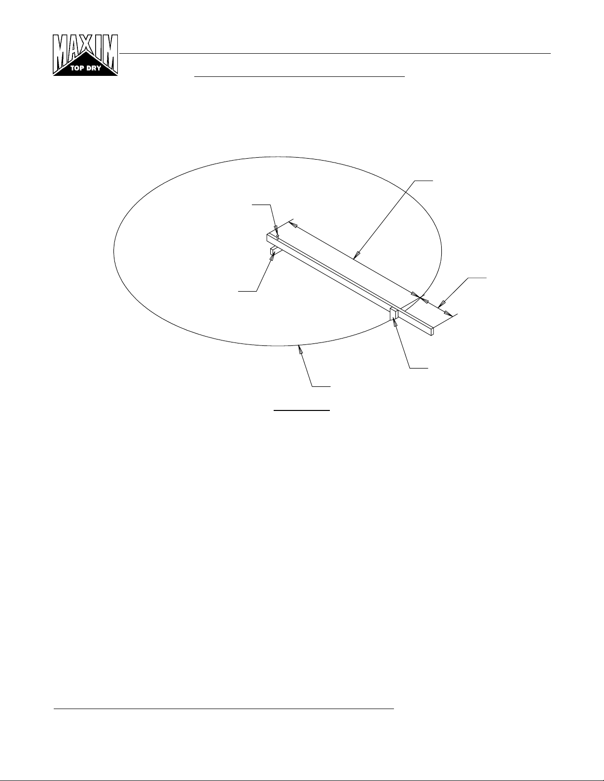
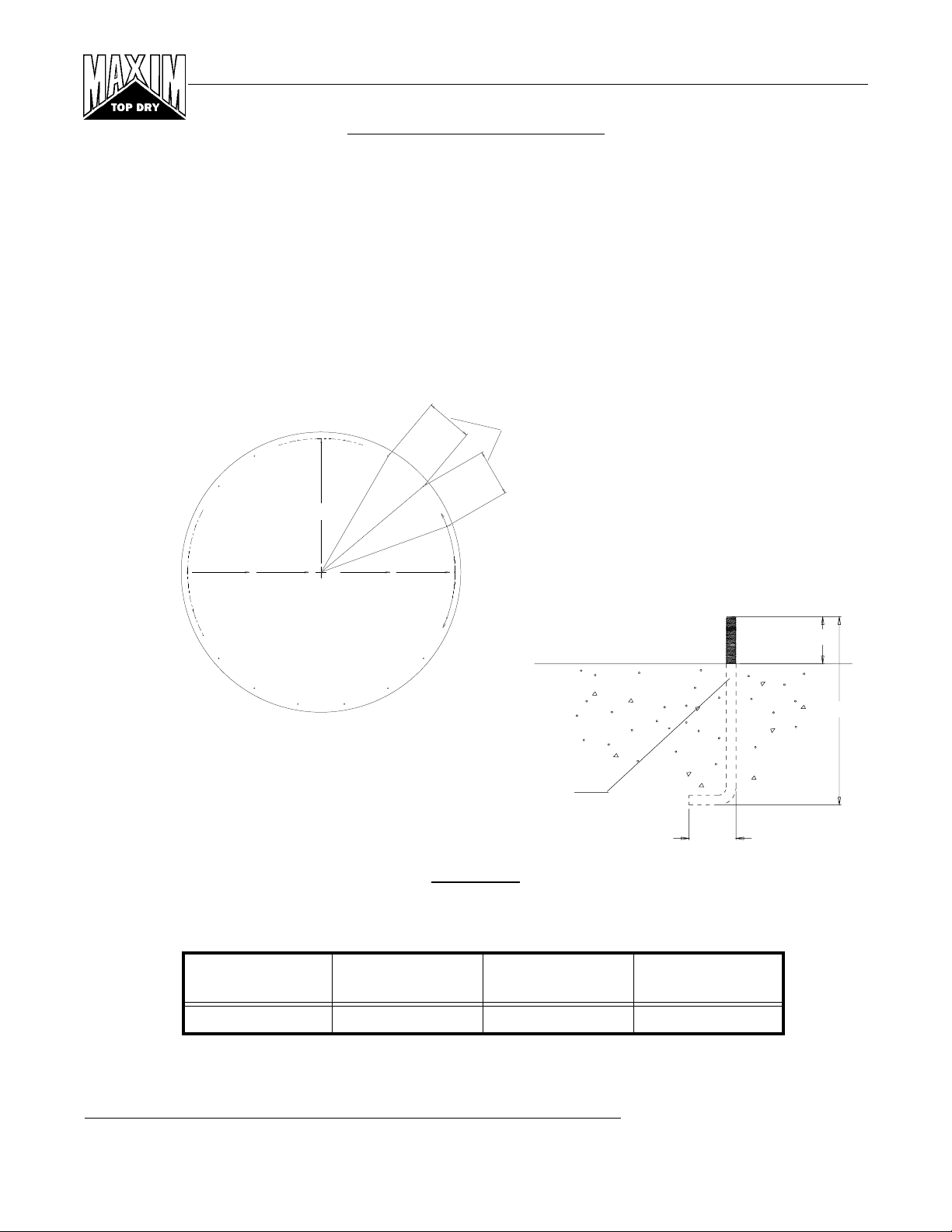
SITE PREPARATION
Foundation Radius
Spike
Two Feet
2 x 4 Center Stake
Pointed Stake
Foundation Line
Figure #1
1.SELECTING THE PROPER SITE
The selected site should be level, firm, and free from underlying debris. The bin can be installed satisfactorily
on slopes, but as the slope increases, additional labor and materials are required for the foundation. The
concrete foundation surface must be level. If some fill is required, it should be watered and tamped
thoroughly to prevent uneven settling from the weight of the bin. Naturally, the site must allow convenient
access for easy loading and unloading, plus provide additional space for future units. Also, consider the
positioning of handling equipment, availability of electricity, and the placement of fans, heaters, and gas
tanks.
2.SCRIBE THE DIAMETER
Having determined the center of the site, drive a small 2 x 4 in the ground to mark the center point of the
foundation. The top of the stake should be the same height as the finished foundation will be. Using one large
spike, nail a straight 2 x 4 (approximately 2 feet longer than the radius of the bin) to the top of the center stake.
This will enable it to swivel. Along the opposite end at a distance given in the foundation layout table, attach
a sharply pointed stake. The swiveling 2 x 4 will act as a compass, enabling you to scribe the correct diameter
of your foundation and later locate the anchor and stiffener bolt locations. (NOTE: Making the 2 x 4 two feet
longer than the radius will allow the 2 x 4 to also be used as a leveling device and for pulling concrete.)
Grain Systems, Inc. Assumption, Ill.
REV. 9-30-96
1
Page 2
18' Manual Batch
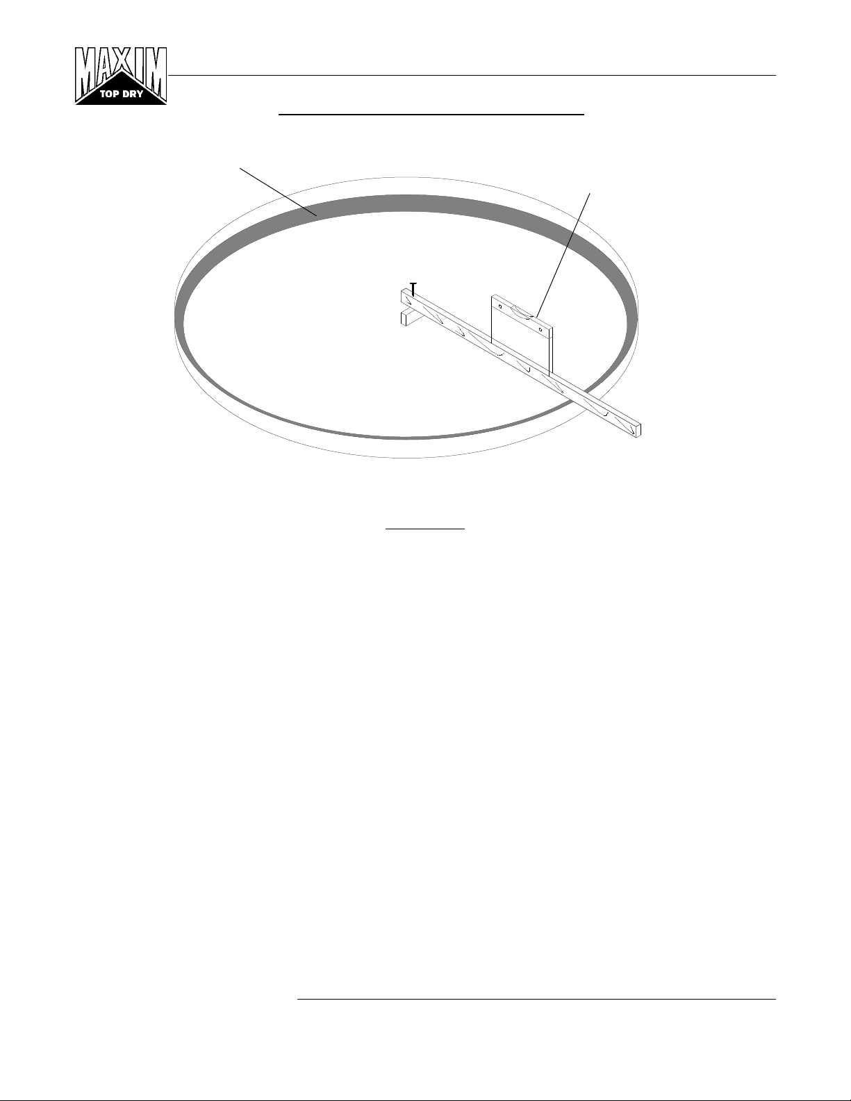
Footing Trench
CIRCULAR FOUNDATION FORM
Carpenter's Level
Figure #2
3.PREPARE THE FOUNDATION
Having scribed the diameter of your foundation, proceed by digging the footing of the foundation. This
consists of a large circular trench dug just inside the foundation line. (Refer to foundation details for necessary
information.) Once the footing has been dug, you are ready to build the forms. It is important that your form
be rigid enough to hold its shape against the poured concrete. Also, the foundation must be flat. Sloped floors
cannot be used in drying bins. A carpenter’s level placed on top of your 2 x 4 will enable you to set the top
of the forms to match the top of the center stake. Check the form work with a transit to ensure a uniform
elevation for the entire foundation.
Grain Systems, Inc. Assumption, Ill.
2
REV. 1-25-96
Page 3
18' Manual Batch
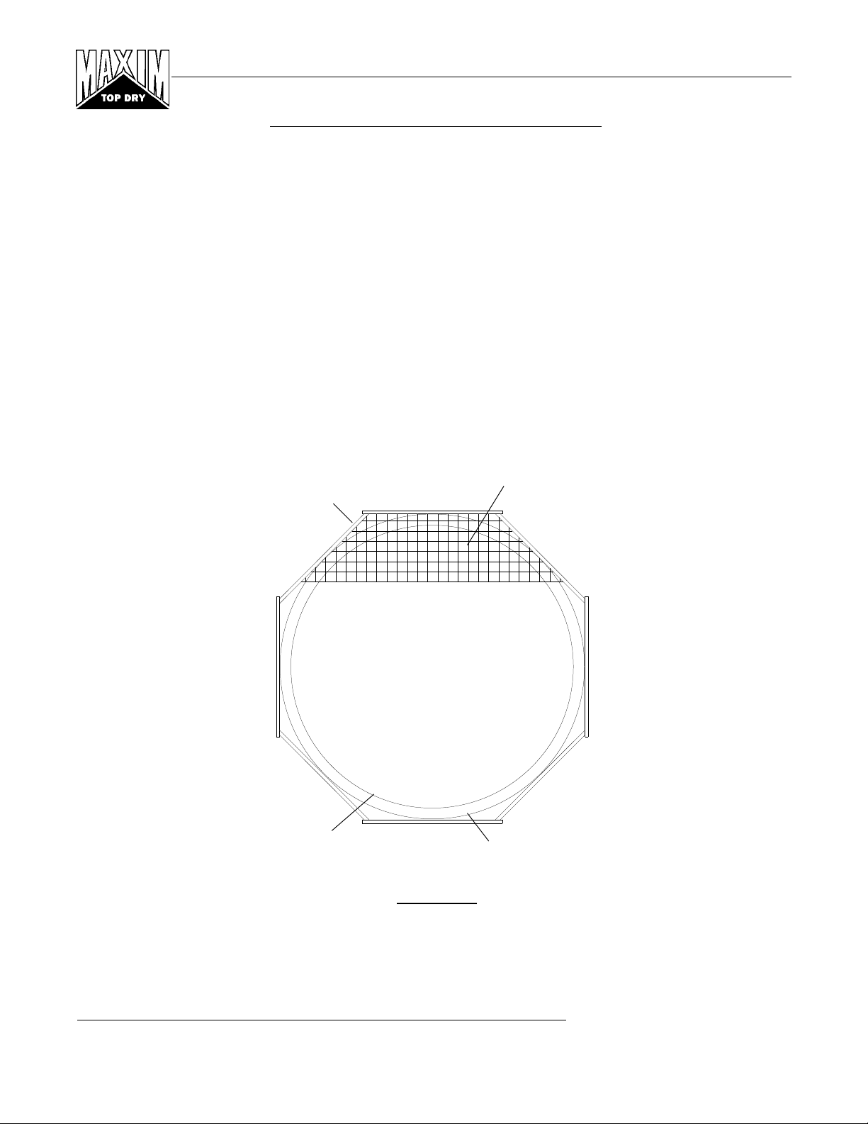
OCTAGONAL FOUNDATION FORM
There are two styles of foundation forms commonly used. The first is the circular form depicted in Figure
#2. The second style can be made of 2" x 8" boards set into a square with corners blocked off to form an
octagon. (See Figure #3 below.) This eight sided form will approximate a circle and can be constructed quite
easily.
When the foundation form is completed install reinforcement rods by either welding or wiring in place. Place
2" of compacted sand on the inside level of the foundation. The sand is then covered with a 4 mil plastic
moisture barrier. 6" x 6" wire mesh (2 mats), covering the entire area of the foundation, completes your
preparation of the bin’s foundation. You are now ready to begin pouring concrete.
NOTE: ALL CONCRETE IS TO HAVE A MINIMUM COMPRESSIVE STRENGTH OF 3,000 PSI
@ 28 DAYS.
6" x 6" Wire Mesh
2" x 8" Forms
Footing Trench
TOP VIEW
Figure #3
Foundation Line
Grain Systems, Inc. Assumption, Ill.
REV. 1-25-96
3
Page 4
18' Manual Batch
1234567890123456789012345
1
5
1
5
1
5
1
5
1
5
1
5
1
5
1
5
1
5
1
5
1
5
1
5
1
5
1234567890123456789012345
FROST FREE PAD
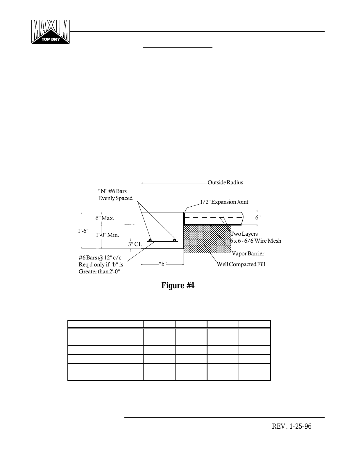
NOTES:
•Foundation site should be well drained and free of vegetation or debris.
•Foundation design is based on a minimum soil bearing capacity of 3,000 lb/ft2. If soil bearing capacity
is in doubt, contact a local soil testing engineer.
•Concrete shall have a minimum compressive strength of 3,000 PSI at 28 days.
•Requirements for reinforcement do not include overlap.
•Lap all circumferential bars 35 bar diameters and stagger all laps in plan 3'-0".
•All material used for back fill inside the ring wall should be a clean, well graded, crushed stone or sandgravel mixture. Back fill should be placed in 6" lifts and well compacted.
Outside Radius
"N" #6 Bars
Evenly Spaced
1/2" Expansion Joint
6" Max.
23456789012345678901234
23456789012345678901234
23456789012345678901234
1'-6"
1'-0" Min.
#6 Bars @ 12" c/c
Req'd only if "b" is
3" CI.
"b"
23456789012345678901234
23456789012345678901234
23456789012345678901234
23456789012345678901234
23456789012345678901234
23456789012345678901234
23456789012345678901234
23456789012345678901234
23456789012345678901234
23456789012345678901234
Well Compacted Fill
Two Layers
6 x 6 - 6/6 Wire Mesh
Vapor Barrier
Greater than 2'-0"
Figure #4
18' Diameter Bin
Ring Number 5678
b 1'-0" 1'-0" 1'-0" 1'-7"
N 2222
Outside Radius 9'-9" 9'-9" 9'-9" 9'-9"
Sq. Ft. Mesh 6 x 6 - 6/6 500 500 500 500
Length of #6 Bars 200 200 200 200
Total Cubic Yd. Concrete 8 8 8 9
6"
Grain Systems, Inc. Assumption, Ill.
4
REV. 1-25-96
Page 5
18' Manual Batch
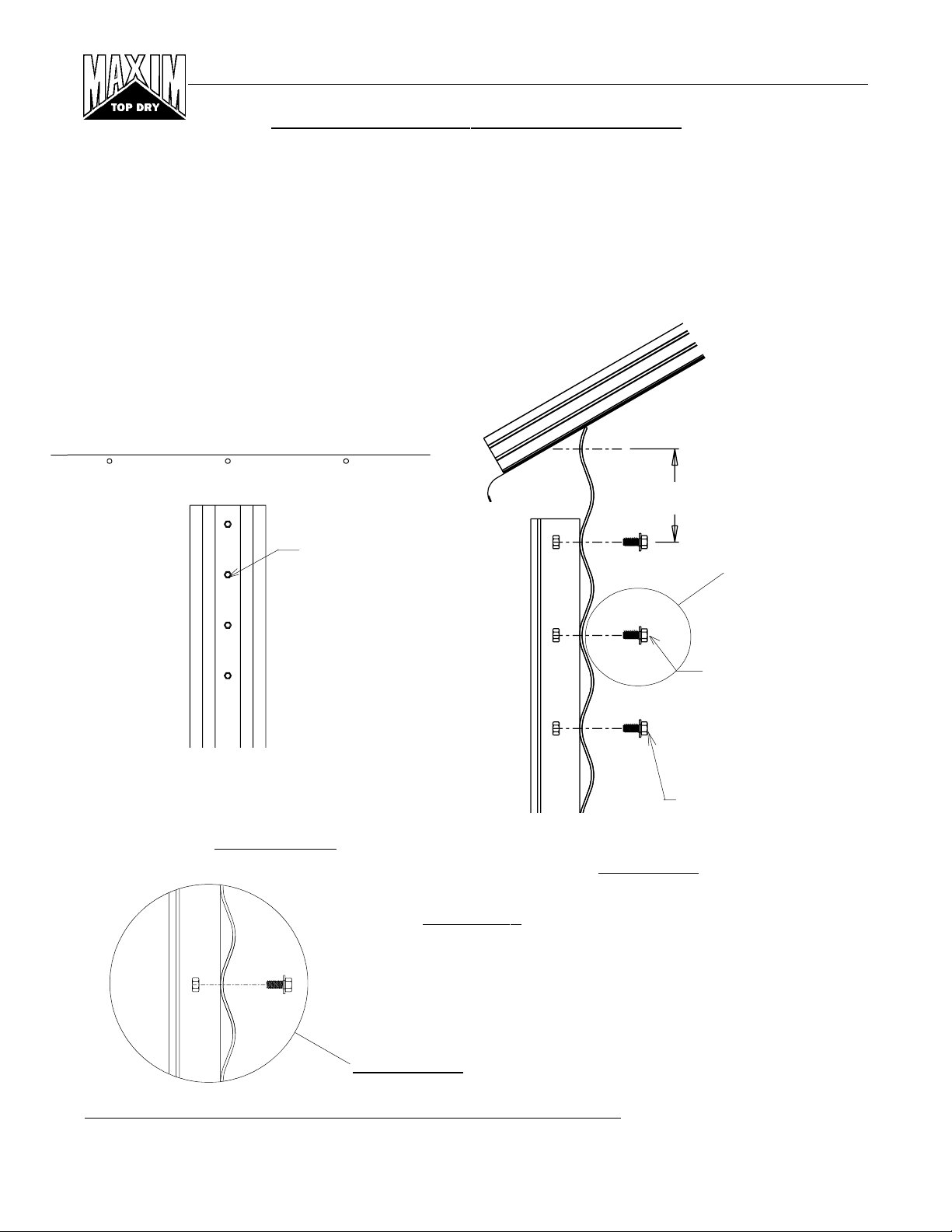
ANCHOR BOLT LAYOUT
Refer to following diagram for proper bolt layout.
Having poured and leveled the concrete, use the center stake and straight 2" x 4" again to find bolt circle radius
for the outside stiffener bolts. Select a starting point and stretch a pre-measured chord along the imaginary
circle formed by the bolt circle radius. Consider the placement of these bolts so as not to interfere with the
positions of bin doors and transitions.
Work both directions from first anchor bolt location, this will help eliminate possible error in laying out
anchor bolts. On larger bins sight across starting anchor bolt and center pin and place anchor bolt on opposite
side of anchor bolt radius. From this point you can work both directions from both anchor bolts.
Bolt Chord
Bolt Radius
Starting
Point
Work Both
Sight Across
Directions
B-5217 5/8" ANCHOR
BOLT ASSEMBLY
Figure #5
5/8" Anchor Bolt Detail
Bin Diameter
18' 9'-3.1/16" 12
Bolt Circle
Radius
Number of
Anchors
3"
12"
3"
Bolt Chord
Distance
4'-9.1/2"
Grain Systems, Inc. Assumption, Ill.
REV. 7-9-96
5
Page 6
18' Manual Batch
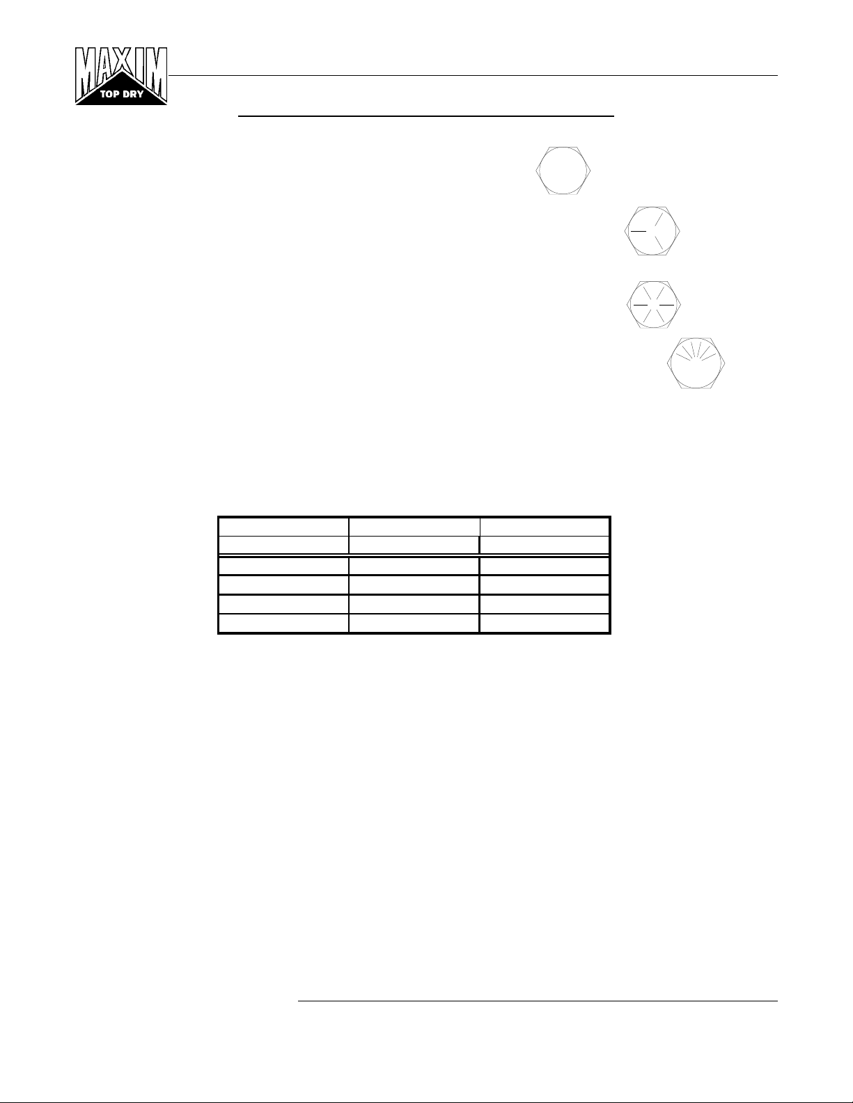
HARDWARE/BOLTING REQUIREMENTS
NOTE: Grade 2 bolts are designated with a plain head.
NOTE: Grade 5 bolts are designated by 3 slash marks on the head.
All 5/16" diameter bolts are to be Grade 5 or higher.
NOTE: Grade 8 bolts are designated by 6 slash marks on the head.
NOTE: Grade 8.2 bolts are designated by 6 slash marks on the head in a
sunrise pattern.
All 3/8" diameter bolts are to be Grade 8 or 8.2.
IMPORTANT: Do not tighten bolts to exceed the torque specifications listed below.
TORQUE (ft. lb.)
BOLT SIZE MINIMUM MAXIMUM
5/16" - 18 15 20
3/8" - 16 35 42
7/16" - 14 65 72
1/2" - 13 95 105
CAUTION: UNDER NO CONDITION SHALL ANY OTHER BOLTS BE SUBSTITUTED FOR
THOSE SUPPLIED BY GRAIN SYSTEMS, INC.
IMPORTANT: HARDWARE USAGE - 20 gauge - 15 gauge sidewall sheets, use
5/16" x 3/4" bolts and nuts. (S-275)
14 gauge and 13 gauge sidewall sheets, use
5/16" X 3/4" bolts and nuts. (S-275)
- Use 5/16" x 1.1/4" (S-277) for attaching floor flashing to the sidewall.
Grain Systems, Inc. Assumption, Ill.
6
REV. 9-28-96
Page 7
18' Manual Batch
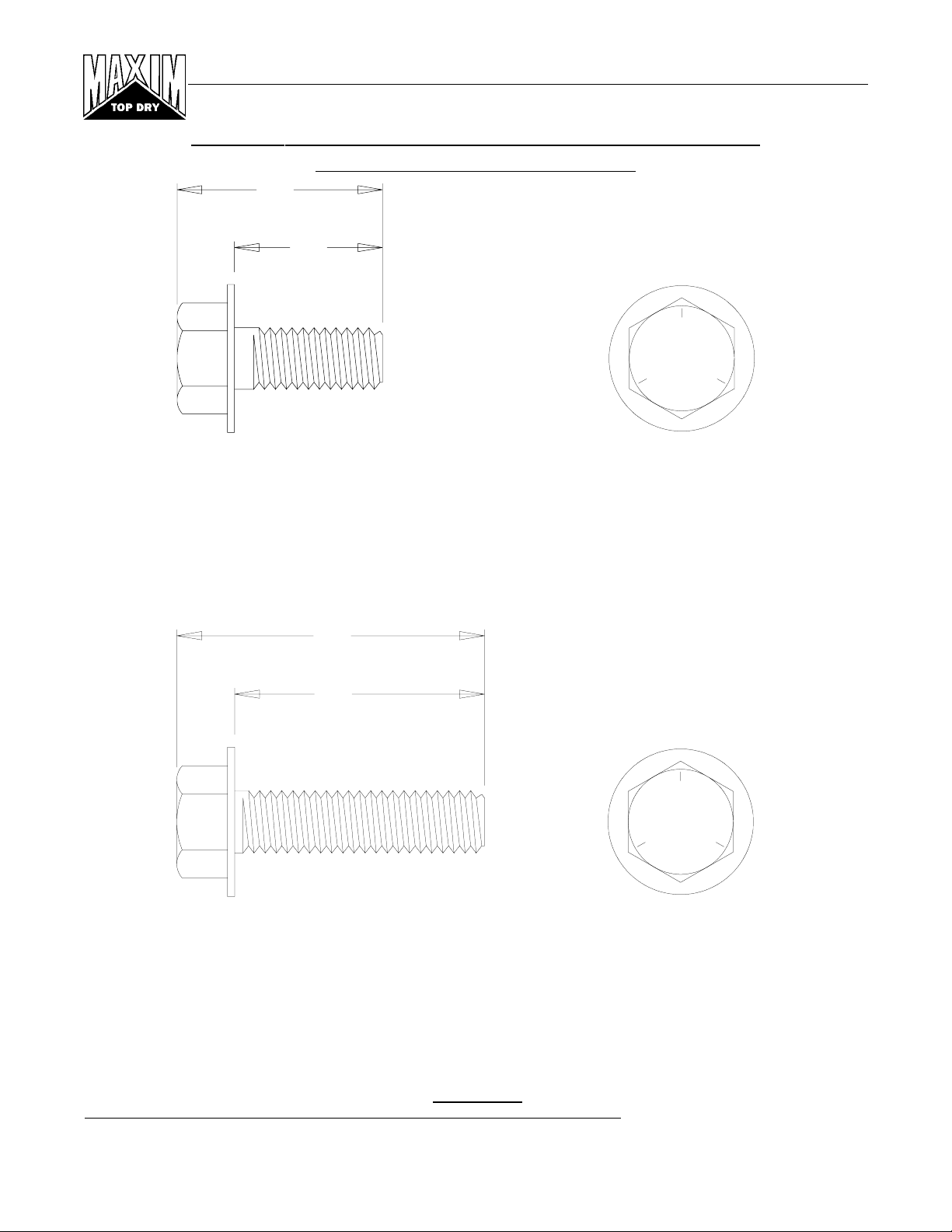
REFER TO TOP DRY TANK BOLTING REQUIREMENTS
FOR COMPLETE BOLT USAGE
.950"
.750"
GRADE 5
SIDE VIEW
TOP VIEW
S-275
.3125" x .750" pre-assembled with a steel backed neoprene washer.
This bolt is used to connect horizontal and vertical seams for 13 gage and thinner sidewall sheets to each
other, and to bolt the stiffeners to the sidewall sheets. It is also used in attaching roof panels to the top
sidewall sheet and attaching roof panels and flashing to the center collar.
1.437"
1.250"
GRADE 5
SIDE VIEW
TOP VIEW
S-277
.3125" x 1.250" pre-assembled with a steel backed neoprene washer.
This bolt is primarily used to connect roof panels together where they overlap. It is also used at the bottom
of the flat bottomed bins to attach the base angle to the sidewall sheet. A small number of these are provided for joints and FC-42076 splice plates for the stiffeners to sidewall connection.
Figure #6
Grain Systems, Inc. Assumption, Ill.
REV. 9-28-96
7
Page 8
18' Manual Batch
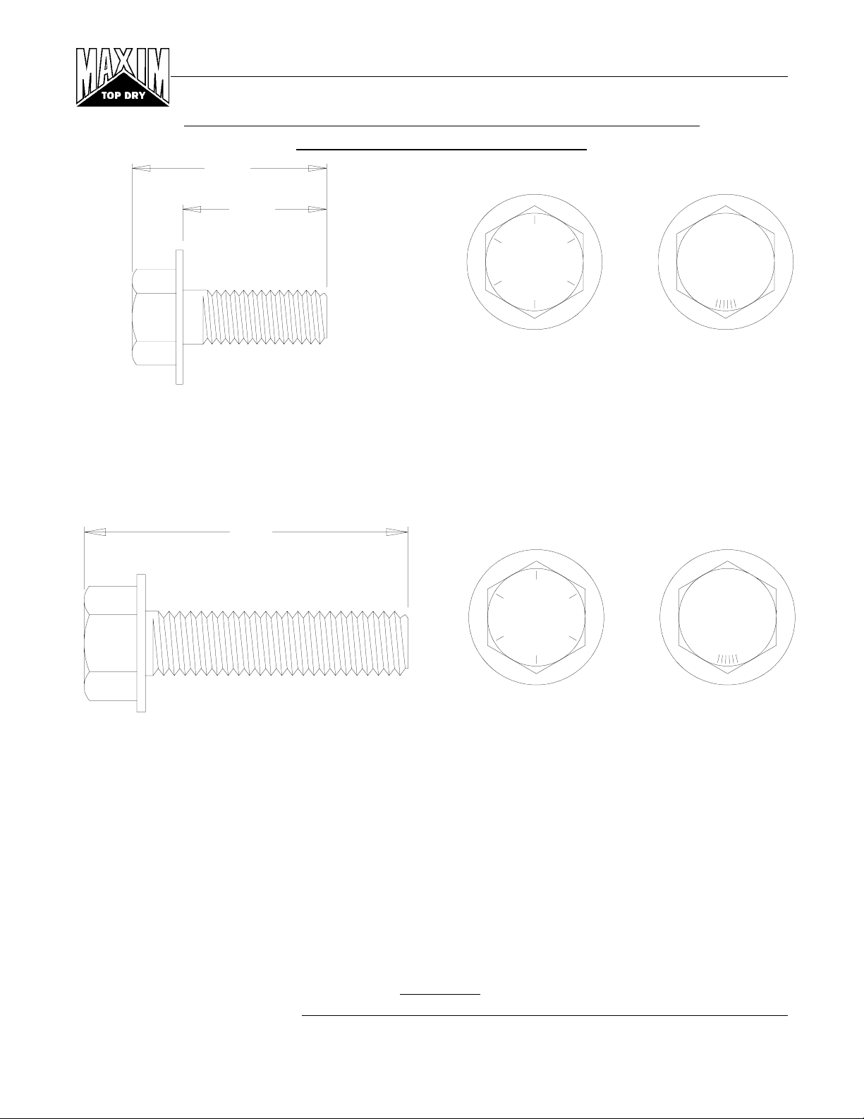
REFER TO TOP DRY TANK BOLTING REQUIREMENTS
FOR COMPLETE BOLT USAGE
1.377"
1.000"
GRADE 8.2
SIDE VIEW
GRADE 8
TOP VIEW
S-7927
.375" x 1.000" hex flanged head without a plastic sealing washer.
This bolt is used to splice the stiffeners together on the flanges. A steel flat washer is used on the nut side
of the connection. They are also used on "c" channel splices and mounting "c" channel to wall bracket.
1.873"
GRADE 8.2
SIDE VIEW
GRADE 8
TOP VIEW
S-7928
.375" x 1.500" hex flanged head without a plastic sealing washer.
This bolt is used to attach the wall bracket to the sidewall and stiffener. A steel flat washer is used on the
nut side of the connection.
Note: The only washers shipped loose with the bins are the steel flat washers. The 5/16" steel flat washer
(S-845) is used where the base angle attaches to the sheet and some are used at the main eave clips. The
3/8" steel flat washers (S-248) are used at the stiffener splices and some are used in the roof rafter splices.
Figure #7
Grain Systems, Inc. Assumption, Ill.
8
REV. 9-30-96
Page 9
18' Manual Batch
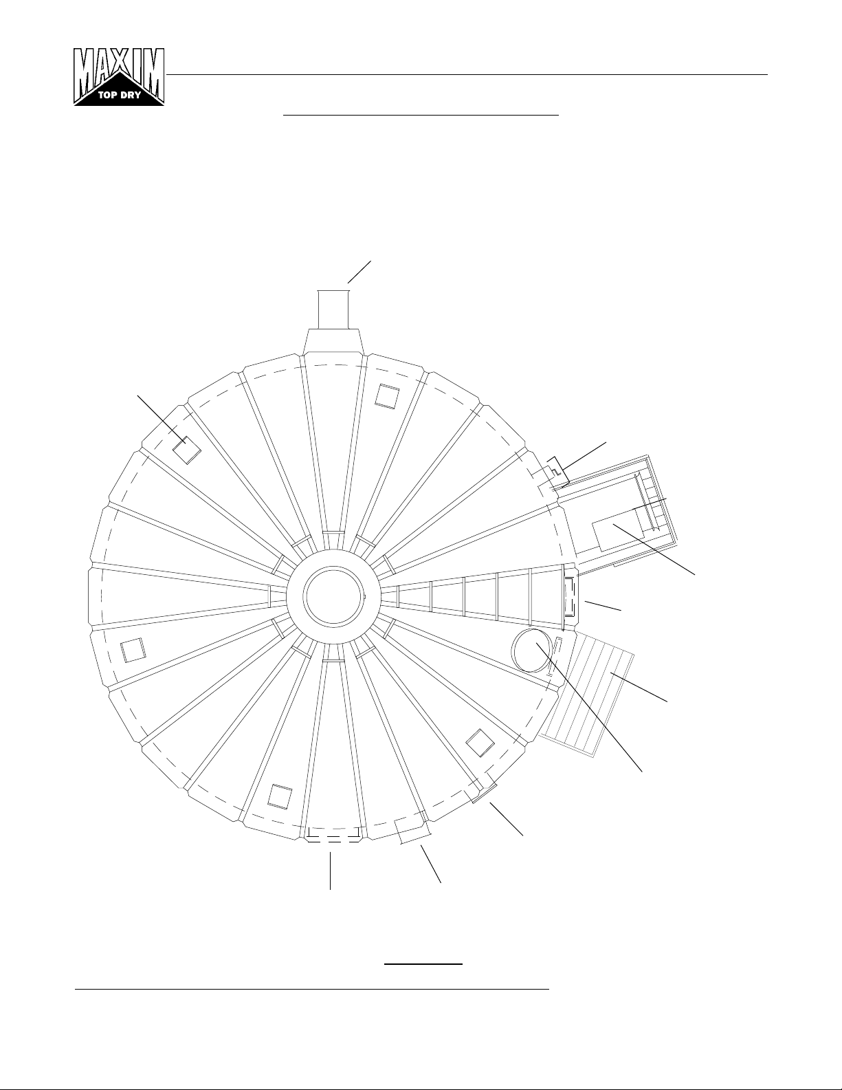
LOCATION OF ACCESSORIES
Below is a typical Top Dry bin layout showing suggested locations of Top Dry Accessories. When locating
the manway be sure the outside ladder will not interfere with other accessories below. Roof vents should be
spaced evenly around the roof. (Quantity will vary with individual systems.)
NOTE: The Top Dry system should be provided with a dependable equipment ground.
Aeration Fan &
Transition
Roof Vents
Manual Winch
2 Ring Door
Crop Dryer
Platform
Top Dry
Crop Dryer Unit
Outside Ladder
Access Door
Platform
Manway
Top Dry
Control Center
Unloading Auger
Figure #8
Grain Systems, Inc. Assumption, Ill.
REV. 9-30-96
9
Page 10
18' Manual Batch
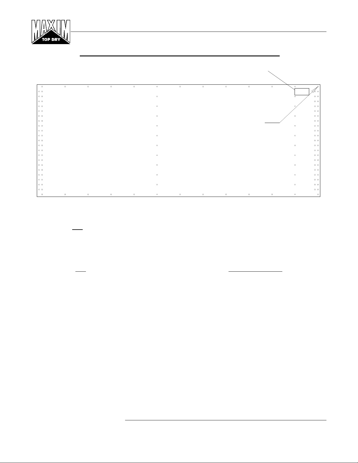
VERY IMPORTANT!
DC-1174 (Top Decal)
Top of Sheet
Horizontal seam hole locations
determine top and bottom of sheet.
Sheet shown as viewed from the inside of bin.
Bottom of Sheet
All 4.00" corrugated sidewall sheets must be placed correctly.
Top
All 4.00" corrugated sidewall sheets have a top and bottom!
Failure to observe this will not allow the door to fit properly.
Carefully review the erection manual and place sidewall sheets as shown.
Grain Systems, Inc. Assumption, Ill.
10
REV. 9-30-96
Page 11
18' Manual Batch
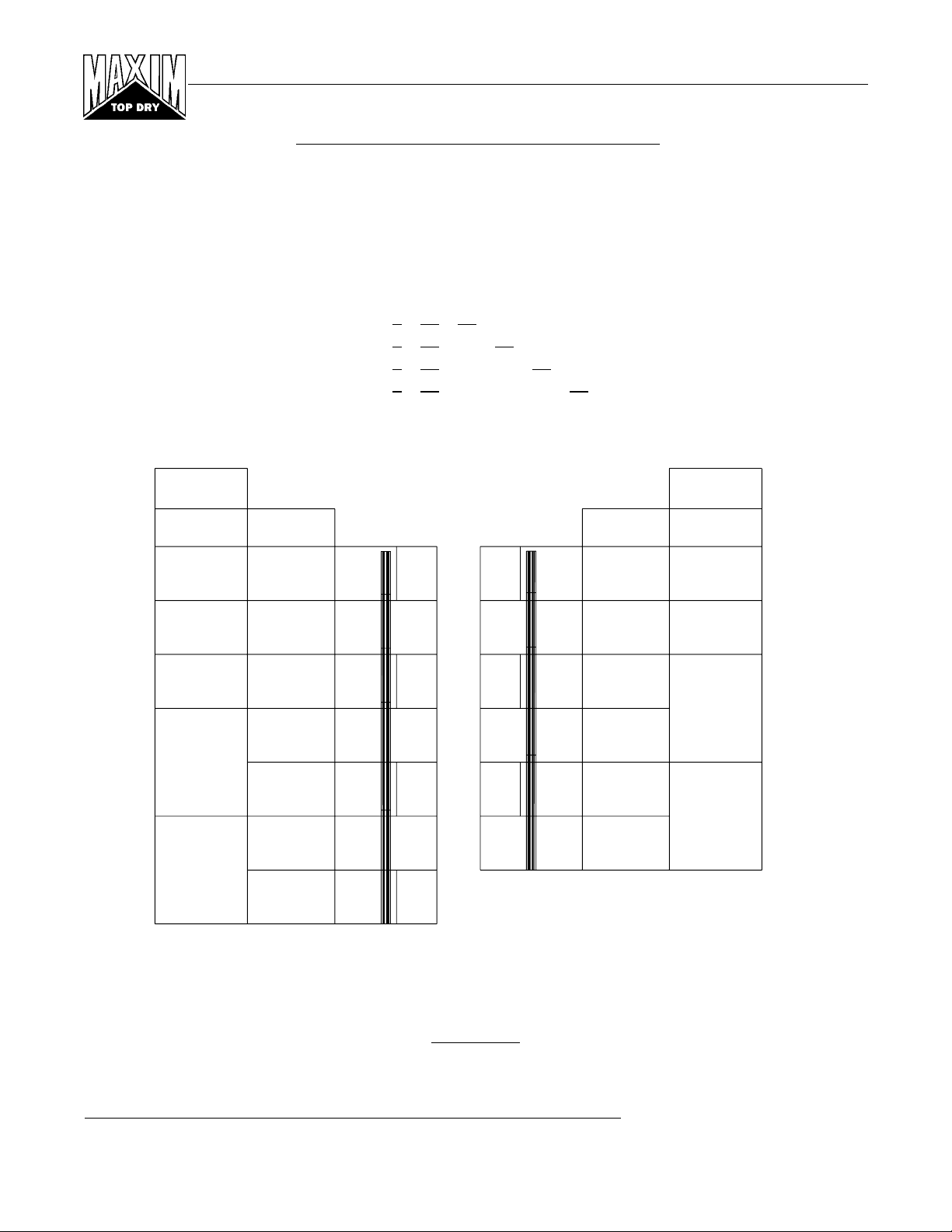
SIDEWALL & STIFFENER GAUGES
Door locations are shown by the underlined sidewall gauges. Actual gauge of the access door sheet located
just below the Top Dry floor is in parentheses.
Top Dry Bin
TDM18-4
TDM18-5
TDM18-6
TDM18-7
Odd Ring
Gauge
16-T*
16
16
Ring
1
2
3
Sidewall Gauges
20 20 20 20 (18)
20 20 20 20 20 (18)
20 20 20 20 20 20 (18)
20 20 20 20 20 20 20 (18)
18' Stiffener Layout
Ring
1
2
3
Even Ring
Gauge
16-T*
16
16
* Top stiffener
4
14
5
6
12
7
4
5
14
6
All Top Dry bin stiffeners are mounted on the outside of the bin. See stiffener instructions for stiffener joint
details and stiffener to sidewall attachment.
Figure #9
Grain Systems, Inc. Assumption, Ill.
REV. 9-30-96
11
Page 12
18' Manual Batch
D
P
L
h
Cod
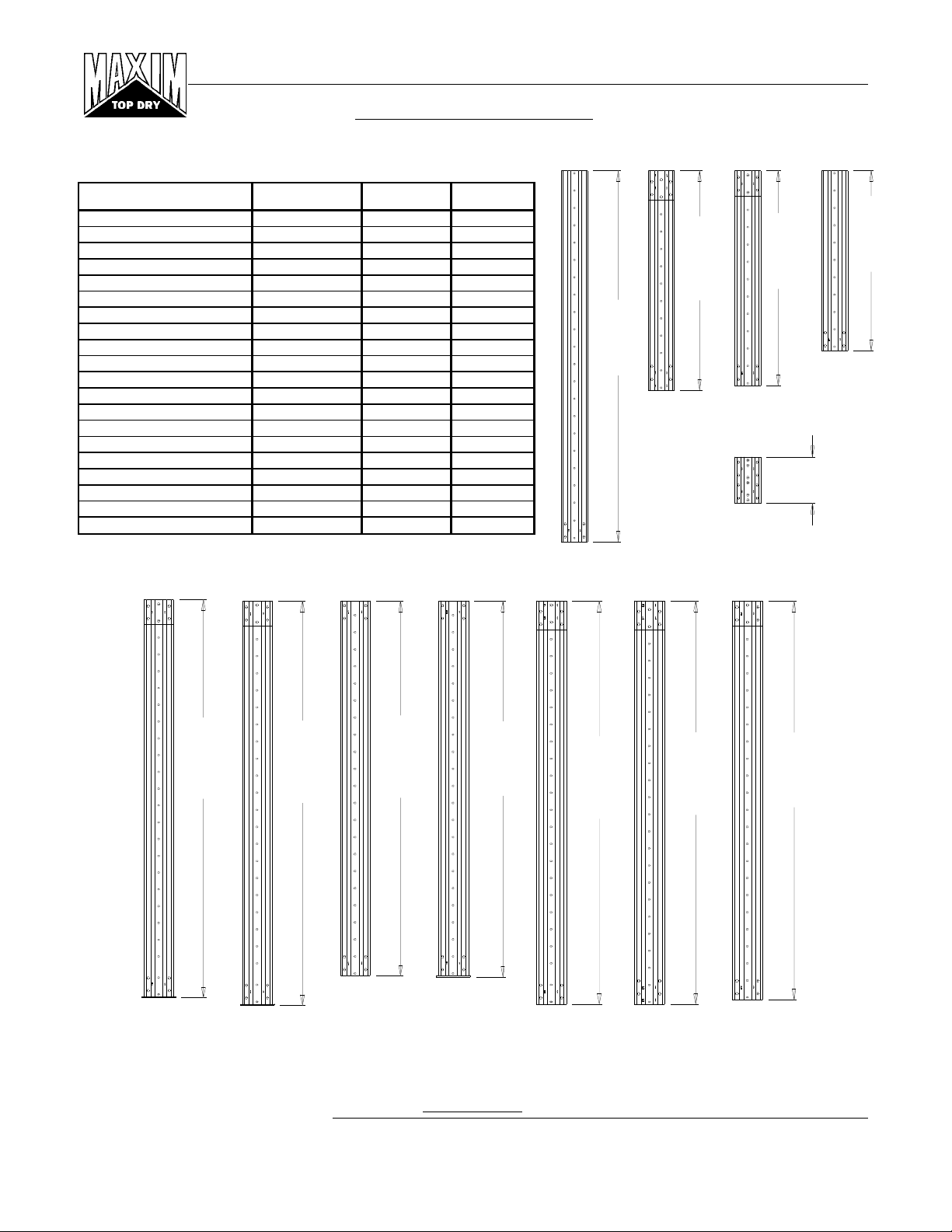
OUTSIDE STIFFENERS
• The XX in the part numbers at the bottom will identify the Stiffener's gauge.
Example: FC-4205714 is a 2-Ring Standard Stiffener 14 Gauge.
Stiffener Overall Color
escription
2-Ring 10 Ga. (Base) FC-4207210 94 27/32" White
2-Ring 12 Ga. (Base) FC-4207212 94 27/32" Black
2-Ring 14 Ga. (Base) FC-4207214 94 27/32" Green
2-Ring 16 Ga. (Base) FC-4207216 93 13/16" Blue
2-Ring 8 Ga. (B ase ) FC-4207308 88 3/16" Yellow
2-Ring 8 Ga. FC-4206308 87 15/16" Yellow
2-Ring 10 Ga. Tr a ns. FC-42062 94 19/32" Purple
2-Ring 12 Ga. FC-4205712 94 19/32" Black
2-Ring 14 Ga. FC-4205714 94 19/32" Green
2-Ring 16 Ga. FC-4207516 93 9/16" Blue
2-Ring 18 Ga. FC-4207518 93 9/16" Orange
2-Ring 16 Ga. Top FC-4206516 85 9/16" Blue
2-Ring 18 Ga. Top FC-4206518 85 9/16" Orange
1-Ring 12 Ga. FC-4205912 50 19/32" Black
1-Ring 14 Ga. FC-4205914 50 19/32" Green
1-Ring 16 Ga. FC-4207416 49 9/16" Blue
1-Ring 18 Ga. FC-4207418 49 9/16" Orange
1-Ring Top 16 Ga. FC-4206616 41 7/16" Blue
1-Ring Top 18 Ga. FC-4206618 41 7/16" Orange
Splice FC-42076 10 11/16" ---
art No.
engt
e
85.9/16"
FC-42059XX
1 Ring
12 Ga.
14 Ga.
FC-42065XX
2 Ring Top
16 Ga.
18 Ga.
50.19/32"
FC-42074XX
1 Ring
16 Ga.
18 Ga.
FC-42076
Splice
10 Ga.
41.7/16"
49.9/16"
FC-42066XX
1 Ring Top
16 Ga.
18 Ga.
10.11/16"
93.13/16"
FC-4207216
2 Ring
16 Ga.
Base
Grain Systems, Inc. Assumption, Ill.
12
FC-42072XX
2 Ring
10 Ga.
12 Ga.
14 Ga.
Base
94.27/32"
FC-42063XX
2 Ring
8 Ga.
87.15/16"
FC-42073
2 Ring
8 Ga.
Base
Figure #10
88.3/16"
FC-42062
2 Ring
10 Ga.
Transitional
94.19/32"
FC-42057XX
2 Ring
12 Ga.
14 Ga.
94.19/32"
FC-42075XX
2 Ring
16 Ga.
18 Ga.
REV. 1-25-96
93.9/16"
Page 13
18' Manual Batch
TOP STIFFENER STARTING LOCATION
Refer to Figure #11, for proper location of top stiffeners. On the overlap of the stiffeners, and on the splice, use
3/8" x 1" hex bolts, a washer on the nut side connection. Refer to the stiffener layout, Figure #9, for stiffener usage.
All stiffeners are outside the bin wall. Use 5/16" x 3/4" Grade 5 bin bolts with head and neoprene washer to the inside
of the bin wall. Refer to proper charts and illustrations on the previous two pages for proper location of stiffeners and
sidewall sheets.
4.00"
TOP STIFFENER
FRONT VIEW
DETAIL "A"
5/16" X 3/4" BIN BOLT
(S-275)
BOLT HEAD AND SEALING
WASHER MUST BE ON THE
INSIDE OF THE BIN.
SIDE VIEW
Figure #11
DETAIL "A"
Grain Systems, Inc. Assumption, Ill.
REV. 9-30-96
13
Page 14

18' Manual Batch
3/8" DIA. HEX FLANGED
HEAD BOLT (NO
SEALING WASHER)
USE 3/8" X 1.1/2"
BOLT, NUT AND WASHER
STIFFENER SPLICE DETAILS
FC-4207516 16 GA.
BLUE
FC-4207518 18 GA.
ORANGE
FC-4207516 16 GA.
BLUE
FC-4207518 18 GA.
ORANGE
SPLICE PLATE JOINT
(TOP VIEW)
3/8" DIA. HEX FLANGED
HEAD BOLT (NO
SEALING WASHER)
FC-4206308 8 GA.
YELLOW
FC-42062 10 GA.
PURPLE
FC-42076 SPLICE
OFFSET JOINT CONNECTION
DETAIL
Grain Systems, Inc. Assumption, Ill.
14
Figure #12
REV. 9-30-96
Page 15
18' Manual Batch
BOLTING REQUIREMENTS
2 STIFFENERS PER SIDEWALL SHEET
Sidew all Horizo ntal Vertical Stif fene r Overlap
Gauge Seam Seam To Sidewall Seam
17 Thru 20 5/16" x 3/4" 5/16" x 3/4" 5/16" x 3/4" 5/ 16" x 3/ 4"
[10] [42] [20] [2]
All bolts are standard bin bolts with neoprene washers. For horizontal and vertical seam bolts, the bolt head and
neoprene washers are on the outside of the bin.
Note: For the splice plates FC-42076 use 5/16" x 1.1/4" bolts for the stiffener to sidewall connections.
Standard (17 Gauge Thru 20 Gauge) Sheet Bolting Detail
(Viewed from outside of the bin)
Vertical Seam
Horizontal Seam
Overlap Seam
Stiffener to
Sidewall
Figure #13
Grain Systems, Inc. Assumption, Ill.
15
REV. 1-25-96
Page 16

18' Manual Batch
Even Ring Bins Odd Ring Bins
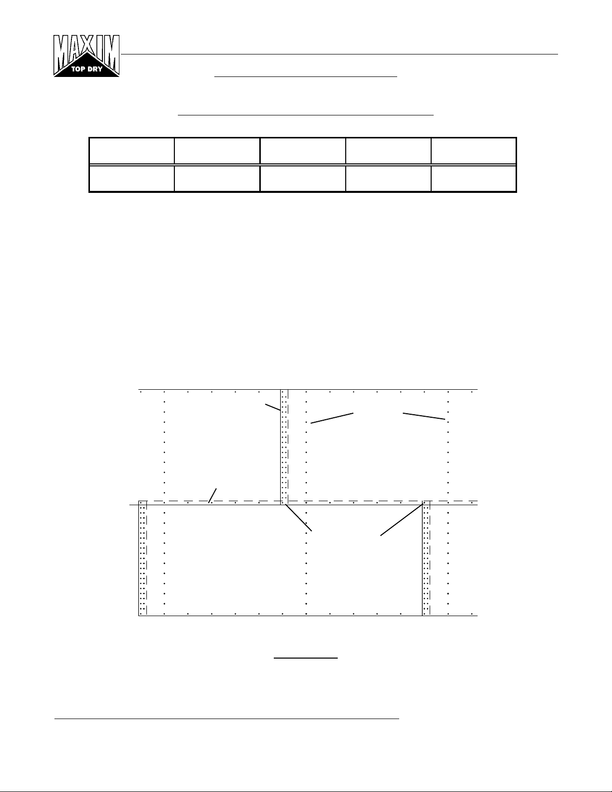
STIFFENER & SEAM LOCATIONS
Horizontal Seam
Horizontal Seam
Horizontal Seam
Horizontal Seam
Horizontal Seam
Horizontal Seam
Grain Systems, Inc. Assumption, Ill.
16
2 stiffeners per sidewall sheet
Top Dry stiffener starting location -18' to 36'
4" corrugation stiffener only
Figure #14
REV. 1-25-96
Page 17

18' Manual Batch
GAUGE COLOR CODE
22 White
20 Red
19 Black/Yellow
18 Orange
17 Pink/Light Blue
16 Blue
15 Brown/Red
14 Green
13 Yellow/Blue
12 Black
11 Pink
10 Light Blue
9 Blue/Orange
8 Yellow
Note: The rope caulking is installed before each sheet is assembled.
Apply rope caulking between the last vertical row of bolts and edge of
outside sheet. There is sufficient caulking for all vertical seams on
storage and drying bins. Wipe sheet clean where caulking is to be
applied.
Before bolting the sidewall sheets together, check that you have the
proper gauge steel for the first ring. The higher gauge numbers denote
the thinner materials. (For example: 20 gauge material is thinner than
14 gauge.) In erecting Top Dry grain bins the thinnest material always
goes on top. The first sidewall ring you assemble will be the second
ring from the top of your bin. Check the various gauges of your bin
with the Color Code Chart and begin building accordingly.
Once you have selected the proper gauge material, begin assembling
the sidewall sheets according to the instructions on the following page.
- For bolting specifications on stiffeners, see Figure #11.
CAULKING DETAIL
9.3/8" (23.813 cm)
Standard
Caulking
9.3/8" (23.813 cm)
Standard Sidewall Sheets
As Viewed From Outside
Figure #15
Grain Systems, Inc. Assumption, Ill.
REV. 1-25-96
17
Page 18

18' Manual Batch
SIDEWALL CONSTRUCTION INSTRUCTIONS
Left
Sidewall
Concrete
Foundation
Right
Sidewall
Figure #16
Using correct size bin bolts throughout, begin assembling sidewall sheets end to end (overlapping the same way
throughout) until the ring is complete. All body sheet bolts are to be installed with the bolt head and its neoprene washer
to the outside and the nut on the inside. Do not tighten bolts until all sheets are assembled and form a complete ring.
Tighten the bolts in sequence, starting from the center and work to the edge in both directions. This permits the sidewall
sheets to draw-up evenly.
After assembling the second ring, lift the top ring sheets in place, add top stiffeners, build the Top Dry floor, then the
roof.
Note: The sidewall sheets used for the top ring are punched to accommodate the eave flashing bolts.
Note: The fan entrance sheet and access door are located in the second ring. Attach the top stiffeners, leaving out
the (7) bolts indicated in Figure #15 at each stiffener location. Install the flashing bolts from the outside.
Top Two Rings
Eave flashing
holes
Leave these 7
bolts out of each
stiffener
TOP RING
SECOND RING
Figure #17
Grain Systems, Inc. Assumption, Ill.
18
REV. 9-30-96
Page 19

18' Manual Batch
STIFFENER AND BRACKET INSTALLATION
Install the stiffeners on the outside of the bin (as shown in Figure #14) and the wall brackets on the inside of the bin.
The wall brackets are to be positioned with the bracket's top hole matching the first hole up from the horizontal seam
(not counting the horizontal seam). Bracket to sidewall connection using a 3/8" x 1.1/2" bolt (S-2086), head outside,
with a neoprene washer (S-3558) against the wall on the inside, and a corrugation spacer (S-7041).
NOTE: It may be necessary to ream out sidewall holes with a drill and 3/8" bit for easier installation.
TD-100667
Wall Bracket
S-7041
Corrugation
Spacer
S-3558
Neoprene
Washer
S-7041
Corrugation
Spacer
TD-100667
Wall Bracket
Figure #18
TOP RING
S-3558
Neoprene
Washer
SECOND RING
Figure #19
Grain Systems, Inc. Assumption, Ill.
REV. 9-30-96
19
Page 20

18' Manual Batch
"C" CHANNEL INSTALLATION
Fasten the rolled "C" eave members to the wall brackets in the upper 2 holes of the top set of three (3) holes leaving
the bolts loose.
Install the splice plates at the rolled "C" eave member seams using 3/8" x 1" flanged hex bolts and nuts. Install bolts
as shown below. Tighten all bolts.
"C" Channel Attachment.
TD-100763
Eave "C" Channel
TD-100763
Eave "C" Channel
TD-100688
Eave Splice
Grain Systems, Inc. Assumption, Ill.
20
Figure #20
REV. 9-30-96
Page 21

18' Manual Batch
CENTER COLLAR ASSEMBLY
Add channel braces and brace plates to center collar as shown using 3/8" x 1" bolts and nuts. (Do not attach cross
channel until floor is done.)
TD-100460
TD-100459
Channel Brace Plate
Channel Brace
TD-100004
Center Collar Cross
Channel
(Don't install until floor
TD-100630
Center Collar
is completed)
Figure #21
Position the center collar at the center of the bin and raise it to approximately 7'-0.3/4" measuring from the
bottom edge of the collar to the concrete.
7'-0.3/4"
Figure #22
Grain Systems, Inc. Assumption, Ill.
REV. 9-30-96
21
Page 22

18' Manual Batch
RAFTER INSTALLATION & FLOOR SUPPORT ANGLE ATTACHMENT
When installing the rafters, set the lower clip end on the "C" eave member. Leave the bolts to the center collar and
the eave member loose until all rafters are in place. Use 3/8" x 1" hex bolts and nuts to connect the center collar and
eave member to three (3) rafters at 90 degrees to each other. These first three (3) rafters should all face the same
direction. Every other rafter should alternate direction. IMPORTANT: There are left & right rafters. Be sure to
alternate left, right, left, right, etc.. The floor sheet support purlins can now be installed using 5/16" x 3/4" bin bolts.
There are two (2) different lengths of purlins to fit between the rafters. Insert the straight tab of the purlin through
the upper slot in the left hand rafter when looking toward the bottom of the rafters. Bolt the bent end of the purlin to
the right hand rafter in the upper two (2) holes. After inserting the next purlin tab, bolt the first purlin tab to the second
purlin. Continue around the bin alternating lengths as the rafter facings did. Tighten all bolts.
Looking toward the sidewall
Floor Support Angle Assembly
TD-100768 Long
TD-100769 Short
Grain Systems, Inc. Assumption, Ill.
22
Figure #23
REV. 9-30-96
Page 23

18' Manual Batch
DUMP HOPPER INSTALLATION
Pre-assemble the dump hoppers, and flashing angles to the floor sheets. Place a dump hopper under the floor sheet
and align it with the pre-punched large hole. Place a flashing angle on top of the sheet across the outer edge of the
hopper entrance with the angles interior angle facing the wide sheet end. Screw down through the angle, sheet, and
hopper with 5/16" x 3/4" self-tapping screws.
TD-100654
Flashing Angle
Floor Sheet
TD-100767
TD-100647
Dump Hopper
Assembly
S-7221
5/16" x 3/4"
Self-Tapping Screws
Figure #24
FLOOR SHEET INSTALLATION
Now the assembled sheets can be placed over the rafter framework. As the sheets are placed and overlapped they are
to be screwed down to the rafters using 5/16" x 3/4" self-tapping screws, leaving the second and sixth holes empty.
18' Floor Sheets
TD-100767
Figure #25
Grain Systems, Inc. Assumption, Ill.
REV. 9-30-96
23
Page 24

18' Manual Batch
LEVELING BAND POST INSTALLATION
Install the leveling band posts on the floor as shown.
The second and sixth holes in the beam indicate the location of the leveling band posts. Attach posts with 5/16" x
1.1/4" bin bolts (S-277). In the second hole from the bottom of the sheet, there will be 6 posts (1 every third sheet).
In the sixth hole there will be 6 posts (1 every third sheet). After all of the posts have been installed fill the unused
holes with 5/16" x 1.1/4" bin bolts.
Optional Rotary Switch
S-277
5/16" x 1.1/4"
Bin Bolt
Leveling Band Post
6th hole from sidewall
Leveling Band Post
2nd hole from sidewall
Grain Systems, Inc. Assumption, Ill.
24
Figure #26
REV. 9-30-96
Page 25

18' Manual Batch
FLASHING BOLT INSTALLATION
Install the eave flashing bolts (5/16" x 1.1/4") through the sidewall and tighten first nut. Note at the vertical
sidewall seams, one bolt is turned around to avoid interference with eave flashing (refer to photo).
Eave Flashing Holes
Left bolt on the each vertical
sidewall seam level with the eave
flashing bolts (as viewed from
inside the bin) is to be installed bolt
in, nut out, as shown in the photo to
the right.
Figure #27
¯
¬
-
#10 Self-Drilling
Screws (S-280)
-
EAVE FLASHING INSTALLATION
Install the eave flashing centered on the floor sheet (1 per) with the bent edge towards
the sidewall install a fender washer (S-3671) and nut. Screw the flashing to the
flashing angle at the dump hopper opening with 5- #10 self drilling (S-280) screws
and screw the flashing pieces together where they overlap with 3 - #10 self drilling
(S-280) screws.
Floor Flashing Angle
(TD-100654)
Figure #28. Flashing Attachment. 1) Sidewall, 2)
Flashing TD-100648, 3) Floor sheet, 4) 5/16" x 1.1/4" bin
bolt. Note that there is a nut in between the sidewall sheet
and the flashing sheet.
Grain Systems, Inc. Assumption, Ill.
REV. 9-30-96
25
Page 26

18' Manual Batch
FLASHING SPLICE INSTALLATION
The flashing splice pieces can now be attached to the eave flashing to seal around the rib of the floor sheet as shown
with (S-280) #10 self-drilling screws. The flashing splice is a break apart piece. Attach the center piece in the center
so that it rests on top of the floor sheet rib. Break off the side pieces and place them such that they seal against the sides
of the ribs and attach each side piece with two screws. Make sure there are no gaps in the flashing.
Top Ring
TD-100649
Eave Flashing
Splice
(as viewed from inside the bin)
TD-100648
Eave Flashing
#10 Self-drilling Screws
(S-280)
OUTER DUMP CHUTES
Bolt a TD-100598 angle dam to each dump chute using (3)1/4" x 5/8" bolts and nuts, as shown below. Use 1/4" x
5/8" bolts and double nuts to fasten dump chutes to hopper. Do not tighten first nut down. Lock second nut to first
nut and make sure chutes raise and lower FREELY!
TD-100647
Dump Hopper Assembly
TD-100598
Angle Dam
TD-100017
Dump Chute
S-1429
1/4" x 5/8" Bolt
S-1102
1/4" Nut (1 per bolt)
S-1102
1/4" Nut (2 per bolt)
Lock together. Don't
tighten first nut down
Grain Systems, Inc. Assumption, Ill.
26
Figure #29
REV. 9-30-96
Page 27

18' Manual Batch
CENTER CONE ASSEMBLY
Bolt the sections together to form perforated cone as shown below. Use 1/4" x 5/8" bolts and nuts to attach sections together.
Flat Overhead View
CENTER CONE INSTALLATION
TD-100219
Perforated Cone
Section (6 Required)
Side Formed View
Formed Overhead View
1/4" x 5/8" Bolts & Nuts
Install cone over the center collar. Fasten Cone Assembly with (12) #10 x 3/4" self-drilling screws (S-280).
#10 x 3/4" Self-Drilling Screw
(12 Equally Spaced)
Figure #30
Grain Systems, Inc. Assumption, Ill.
REV. 9-30-96
27
Page 28

18' Manual Batch
ROOF ASSEMBLY
SPECIAL INSTRUCTIONS
It is now time to assemble the roof. When starting, align manway and ladder such that it coordinates with the other
accessories and does not interfere. The roof is assembled according to the instructions in the roof hardware box,
WITH THE FOLLOWING EXCEPTIONS:
1. Locate eave clips so that a roof sheet will be centered over sidewall ladder.
2. Four eave clip shims per eave clip must be installed.
3. Use TD-100274 Roof Brackets shipped in the Top Dry hardware rather than the brackets shipped in the roof
hardware.
Eave Clip Assembly
TD-100045 (4)
Eave Clip Shim
TD-100274
Roof Bracket
R-007-2
Small Eave Clip
Top Ring Sidewall Sheet
Figure #31
LEVELING BAND LOCATION
Position leveling bands as shown in the drawings below.
Use (2) 5/16" x 3/4" bin bolts to attach bands to posts. Also use 5/16" x 3/4" bin bolts to join band sections. Note
that band sections connect to each other only at endmost holes until completing the circle where an overlap
may occur.
Outer Leveling Bands
TD-100662 15.2"
6.3/8"
Inner Leveling Bands
TD-100661 10"
6.13/16"
4.3/8"
TD-100660 7.2"
TD-100661 10"
2.3/16"
Grain Systems, Inc. Assumption, Ill.
3 Band Sections per Ring
13 Holes Between Posts
28
4.3/8"
TD-100660 7.2"
TD-100661 10"
.3/16"
6 Band Sections per Ring
27 Holes Between Posts
Figure #32
REV. 9-30-96
Page 29

18' Manual Batch
PULLEY ASSEMBLY
Finish assembling the center collar by adding the cross channel. Position the pulley assembly to the cross channel in
the middle of the center collar assembly. Use a 3/8" x 1" hex head cap bolt to fasten assembly to the cross channel.
Position the pulley in the direction of the desired winch location on the sidewall.
TD-100022 Pulley Bracket
S-4750 1/2" x 1.1/2"
S-845 Flatwasher
Shoulder Bolt (Round Head)
S-396 3/8" Nut (2)
TD-100089
Pulley Assembly
S-3949 3/8" x 1" Hex Bolt
Field drill (5) 3/8" diameter holes as shown below. Attach the pulley assembly with 5/16" x 3/4" bolts with the
neoprene on the inside of the bin.
12" from center of hole on the overlap
Bottom edge of top ring
(horizontal seam)
between top sidewall sheet and second
ring sidewall sheet
TD-100038 Lg.
Pulley Bracket
S-4749 1/2" x 1.1/4"
Shoulder Bolt
TD-100089
Pulley Assembly
Figure #33
Field drill 1/2" dia. hole
TD-100039
Sm. Pulley Bracket
S-845 Flatwasher
S-396 3/8" Nuts
Grain Systems, Inc. Assumption, Ill.
REV. 9-30-96
29
Page 30

18' Manual Batch
DUMP CHUTE CHAIN ASSEMBLY
Attach all 18 dump chute chains directly to the lift plate as shown in diagram below.
Install all chains using "S" hooks (S-4692) to attach the chains to the dump chutes and lift plates. Keep excess chain
at the lift plate. Adjust the chains until the chutes are approximately level when the lift plate is in the closed (up)
position. Once the chains are uniformly adjusted, crimp the "S" hooks closed. Check when attaching the "s" hook to
the end link on a chain that the end has not been cut open. If this is found remove the end link or shift up and use the
next link in chain. The lift plate should be approximately 12" down from the cross channel when the chutes are level.
Chain leading to outer chutes
(82") Adjust length as required
TD-100205
Center Lift Plate
(TD-100801)
Crimp "S" hooks after
final chute adjustment
Loop in Cable
Cable Clamp
S-4693
Chutes in closed position
Center Collar
Cross Brace
12" when chutes
are level(closed)
To sidewall pulley
assembly
Lift Plate
Grain Systems, Inc. Assumption, Ill.
30
Figure #34
REV. 9-30-96
Page 31

18' Manual Batch
Roof Ladder
Field cut notch
Support Channel
Note: Field cut rounded notches
in the outer leveling band(s)
where the two roof support
Round corners to
prevent tearing
channels hang from the roof ribs.
Top Leveling Band
Figure #35
WINCH ASSEMBLY
Complete erection of bin. Install winch as shown using 5/16" x 3/4" bin bolts to attach to the sidewall. The cable clamps
from either side of the pulley on the cross channel should be removed and the dump chutes pulled tightly shut. Check
for the uniformity of the chains on the dump chutes and readjust if needed. The downward travel of the chutes must
be limited to prevent damage on new Top Dry bins. This can be done after the bin is complete and the cable stop bracket
and clamp is set to indicate when the dump chutes are fully closed. Open the chutes until the cable clamp is about 30"
above the cable stop bracket. Attach another cable clamp just below the small outside pulley bracket making sure it
is tight.
TD-100040
Winch Stop Bracket
S-4691
Winch
Outside pulley
brackets
Cable clamp
Cable stop
TD-100041
Winch Mount Bracket
Figure #36
Cable clamp to
limit downward
travel of chutes
Sidewall
30"
Grain Systems, Inc. Assumption, Ill.
REV. 9-30-96
31
Page 32

18' Manual Batch
TD-100099
Fan Adapter (28")
FAN ENTRANCE SHEETS
24" thru 36" Fans
TD-100680
36" Fan Entrance Sheet
TD-100206
Fan Adapter-Blank
TD-100098
Fan Adapter (24")
Figure #37
Grain Systems, Inc. Assumption, Ill.
32
REV. 9-30-96
Page 33

ACCESS DOOR WELDMENT ASSEMBLY
DOOR COVER
ACD-4504
ACD-4513
ACD-4514
3/8" X 1.1/2" FULL THREADS
ACD-4515 (2)
**3/8" WASHERS
(USE AS NEEDED)
INNER DOOR ACD-4508
S-3867 (2)
ACD-4509
18' Manual Batch
ACD-4510 (2)
3/8" X 1" BOLTS
Grain Systems, Inc. Assumption, Ill.
#10 SCREWS
REV. 9-30-96
33
ACD-4505
5/16" X 3/4" BOLTS
5/16" X 3/4" BOLT & NUT
ACCESS DOOR WELDMENT
Figure #38
**THE QUANTITY OF 3/8" WASHERS
NEEDED MAY VARY DEPENDING ON
THE SIDEWALL GAUGES.
Page 34

18' Manual Batch
LIFTING JACKS & BRACKETS
NOTE: The number of lifting jacks required is best determined by personal experience. Factors such as bin
size, soil compaction, wind velocity, jack design, etc., are all to be considered when deciding how many to
use. If in doubt, use one jack on every other stiffener. GSI recommends heavy duty jacks rated at 6,000 lbs.
or more.
TD-100724
Optional
Lifting jack
bracket
Figure #39
Remember to attach lifting brackets to the stiffeners. A special optional lifting bracket is available from
G.S.I.
Anchor all jacks securely and raise the bin just high enough to assemble the next ring. When lifting your bin,
raise all jacks at an equal rate. This will prevent the bowing of previously assembled rings and make for easier
hole alignment. Bolt the next ring to the inside of the second ring. Be sure to stagger the sheets and select
the proper gauge material. Lower the bin on the foundation after assembling and tightening the bolts on the
new ring. Now rebolt the lifting straps, continue ring additions until you are ready for door installation.
Lifting Jacks
Figure #40
Grain Systems, Inc. Assumption, Ill.
34
REV. 1-25-96
Page 35

DETAILED LAYOUT FOR PROPER LOCATION OF PLATFORMS
Outside
Ladder
TDP-5008
Sidewall Brace
18' Manual Batch
Grain Systems, Inc. Assumption, Ill.
REV. 1-25-96
35
Inside
Ladder
Access Door Platform
TD-100686
Small Platform
Vertical Support
Small Platform
Figure #41
Page 36

18' Manual Batch
ACCESS DOOR PLATFORM
Before assembly of any platform, read the entire instructions to assure proper placement and assembly.
Refer to Figure #41 for proper location of access door platform. Begin by assembling the access door platform support
frame using 5/16" x 3/4" truss head bolts and nuts. When attaching platform vertical support to bin sidewall field drill
(16) 3/8" diameter holes for each support spaced every 4". Be sure and use 5/16" x 3/4" bin bolt on vertical support
to sidewall. Special attention should be taken when assembling the platform support that the support brace is placed
correctly.
Now proceed to the platform floor. Align holes on platform floor with holes on platform support and bolt together
using 5/16" x 3/4" truss head bolt and nuts. Next, assemble handrail posts, handrails, and handrail braces.
7th hole
3rd hole
9
1
11th hole
2
5
4
5
8
&
13
7
10
6
11
IMPORTANT: Position support
Platform Support
TDP-5009
Figure #42
as shown for proper fit.
Key Part No. Description Quantity Weight
1 LS-371 Platform Vertical Angle 42" 3 11.38
2 TDP-5000 Handr ail 59" 2 10.15
3 TDP-5002 Handr ail 30" 2 10.15
4 TDP-5003 Handrail Brace 36.29/32" 2 6. 34
5 T DP-5005 Floor Brace 58.1/2" 3 26.11
6 TDP-5006 Platform Floor 37.7/8" 2 38.23
7 T DP-5007 Support Brace 50.21/32" 2 15.08
8 TDP-5008 Sidewall Brace 58" 2 19.65
9 TDP-5009 Platform Support 43.1/2" 2 12.95
10 TDP-5010 Platform Floor Splice 37.1/2" 1 6.24
11 TDP-5011 Platform Toe Plate 29.3/4" 1 3.29
12 TDP-5014 Access Door Pack age Hard wa re 1 5.4 1
13 TDP-5008N Sidewall Brace 2.66" 2 16. 61
3
Grain Systems, Inc. Assumption, Ill.
36
REV. 9-30-96
Page 37

18' Manual Batch
SMALL PLATFORM ASSEMBLY
For 36" Fans and Smaller or
with #1 fan when two 36" or smaller fans are installed
Before assembling any platform, read all of the instructions first to assure proper placement and assembly.
Refer to Figure #41 for proper location of small platform. Begin by assembling the small platform support frame using
3/8" x 1" bolts on all connections. Use 5/16" x 1.1/4" bin bolt to attach platform vertical supports to sidewall stiffeners.
Be sure and locate the 5/16" x 1.1/4" bolts from the inside of the bin to the outside. This will provide maximum weather
protection.
12
12"
13
Horizontal Seam
14
Small Platform
36" Fans and Smaller
TD-100092
Figure #43
Key Part No. D escription Quantity Weight
1 TD-100051 Channel Bracket 8 3.90
2 TD-100052 Handrai l Post 49.3/4" 4 31.69
3 TD-100059 Long Toeboard 78.1/2" 2 10.96
4 TD-100060 Short Toeboard 54.1/2" 1 3.80
5 TD-100061 Long Handrail 78.1/2" 4 37.52
6 TD-100062 Short Handrail 54.1/2" 2 13.02
7 TD-100064 Floor Plank 78" 11 112.87
8 TD-100066 "X" Brace Strap 60" 4 7.26
9 TD-100067 Mid Channel Support 74" 2 32.73
10 TD-100070 Side Channel Support 78.1/2" 2 41.26
11 TD-100072 E nd Ch an n el Support 78.1/2" 2 41.60
12 TD-100686 Vertical Support 70" 2 43.11
13 TD-100083 Support Channel 80.7/8" 2 32.98
14 TD-100084 Kn ee Brace 83.5/8" 2 23.67
15 TD-100090 Small Platform Hardware Package 1 8.96
Grain Systems, Inc. Assumption, Ill.
REV. 9-30-96
37
Page 38

18' Manual Batch
1
11
SMALL PLATFORM
36" Fans and Smaller
TD-100092
Position the vertical support
to the existing sidewall
stiffeners as shown in Figure
#41 and double nut with 5/16"
nuts.
8
10
9
6
4
7
5
When bolting stiffener to sidewall
at locations where platform
supports are to be attached, use
(25) 5/16" x 1.1/4" bin bolts, heads
2
to inside. Start 12 inches below
horizontal seam of second and third
rings from top. See Figure #41.
3
Grain Systems, Inc. Assumption, Ill.
38
Figure #44
REV. 9-30-96
Page 39

18' Manual Batch
CROSS OVER PLATFORM ASSEMBLY (For use with stairs)
TDP-5013
Before assembly of any platform, read the entire instructions to assure proper placement and assembly.
Refer to Figure #41 for proper location of cross over platform. Begin by assembling the cross over platform support
frame using 5/16" x 3/4" truss head bolts and nuts. When attaching platform vertical support to bin sidewall field drill
(16) 3/8" diameter holes for each support spaced every 4". Be sure and use 5/16" x 3/4" bin bolt on vertical support
to sidewall. Special attention should be taken when assembling the platform support that the support brace is placed
correctly.
Now proceed to the platform floor. Align holes on platform floor with holes on platform support and bolt together
using 5/16" x 3/4" truss head bolt and nuts. Next, assemble handrail posts, handrails, and handrail braces.
2
7
5
3
1
8
4
6
Figure #45
Key Part No. Description Quantity Weight
1 LS-371 Platform Vertical Angle 2 7.59
2 TDP-5001 Handrail 27" 2 4.63
3 TDP-5003 Handrail Brace 36.29/32" 2 6.34
4 T DP-5004 Short Floor Brace 26.1/2" 3 11.85
5 TDP-5006 Platform Floor 37.7/8" 1 19.11
6 T DP-5007 Support Brace 50.21/32" 2 15.08
7 TDP-5008 Sidewall Brace 58" 2 19.65
8 TDP-5009 Platform Support 43.1/2" 2 12. 95
TDP-5015 Cross Over Plat. Hdw. Pack. 1 3.95
Grain Systems, Inc. Assumption, Ill.
REV. 9-30-96
39
Page 40

18' Manual Batch
PERFORATED CENTER BAND
Drill (6) 3/8" diameter holes equally spaced as shown above for top band clips. Attach clips using 5/16"
x 3/4" bin bolts. Add perforated band sections. Note that these do not attach to the leveling bands but
hang down on the inside of the top inner leveling band.
Measure down 24.1/2"
from first hole in roof
sheet and drill hole for
band clip.
Roof Sheet
TD-100107
Top Band Clip
(6) Equally spaced
Grain Systems, Inc. Assumption, Ill.
40
TD-100545
(3) Perforated Band
Figure #46
REV. 9-30-96
Page 41

18' Manual Batch
OPTIONAL ROTARY SWITCH ROOF LOCATION
Overhead View of optional rotary Switch Location
Fill Spout
Optional Rotary Switch
OPTIONAL ROTARY SWITCH PANEL LOCATION
Drill 2" diameter holes through roof panels at locations shown above. Use a mounting plate as a pattern and drill
(4) 3/8" holes through roof panels at each switch location so the plate can be bolted to the roof.
Field Drill 2" Hole
Top Dry Bin
Diameter
18'
"A"
23.50"
Figure #47
Grain Systems, Inc. Assumption, Ill.
REV. 9-30-96
41
Page 42

18' Manual Batch
INSTALLATION OF OPTIONAL ROOF-MOUNTED LEVEL SWITCHES
Attach flex-coupling to the power-pak and install roll pin. Apply teflon tape or pipe sealant (not included) to power-pak pipe threads and thread power-pak into mounting plate coupling. Conduit opening
in power-pak should be at right angles to roof rib or face toward eave.
Caulk underside of mounting plate above and both sides of 2" hole. Bolt to roof panel.
Overflow Level Switch
TAF-6103
1
2
30º Roof Panel
3
4
5
Figure #48
Key Part No. Description Quantity Weight
1 TD-100076 Rotary Switch Power-Pak 1 3.50
2 TD-100627 Roof Moun t Coup lin g Weld ment 1 2.14
3 TD-100075 Flex-Coupling 1 0.50
4 S-7241 1/8" x 1. 1/ 4" Cotter Pin 2 0.02
5 T AF-6086 3-Vane Paddle 1 0.75
* T AF-6097 Hardware Package 1 0.98
-- PNEG-300 Rotary Switch Instructi ons 1 0.04
-- S-275 5/16" - 18 x 3/4" Bin Bolt 6 0.16
-- S-3651 Tube Seal 1 0.74
-- S-396 5/16" - 18 Hex Nut 6 0.06
-- S-7241 1/8" x 1.1/4" Cotter Pin 2 0. 02
* Hardware Package not
shown
- Included in Hardware
Package
Grain Systems, Inc. Assumption, Ill.
42
REV. 9-30-96
Page 43

18' Manual Batch
INSTALLATION OF OPTIONAL WALL-MOUNTED ROTARY SWITCH
Wall Mount Rotary Switch
TAF-6106
2
Outside of bin
5
sidewall
IMPORTANT:
Inside of bin
sidewall
5
Inside of bin
sidewall
4
3
2.66" Corrugation
2
4
3
4.00" Corrugation
Note: Wall mounted
switch must be located at
least 3' below the bottom
of the fan opening.
Outside of bin
sidewall
1
Figure #49
Key Part No. Description Quantity Weight
1 TD-100076 Rotary Switch Power-Pak 1 3.50
2 TD-100629 Roof Moun t Coup lin g Weld ment 1 2.14
3 TD-100075 Flex-Coupling 1 0.50
4 S-7241 1/8" x 1. 1/ 4" Cotter Pin 2 0.02
5 T AF-6085 1-Vane Paddle 1 0.75
* T AF-6097 Hardware Package 1 0.98
-- PNEG-300 Rotary Switch Instructi ons 1 0.04
-- S-275 5/16" - 18 x 3/4" Bin Bolt 6 0.16
-- S-3651 Tube Seal 1 0.74
-- S-396 5/16" - 18 Hex Nut 6 0.06
-- S-7241 1/8" x 1.1/4" Cotter Pin 2 0. 02
Grain Systems, Inc. Assumption, Ill.
REV. 9-30-96
43
Page 44

18' Manual Batch
TRANSITION INSTALLATION (TR-4734)
BEFORE CUTTING THE OPENING CHECK THAT TR-4734 IS THE TRANSITION THAT WAS
ORDERED.
When installing the GSI aeration transition, it will be necessary to field cut a hole into the bottom sidewall
ring (usually straight across from the unload auger). Refer to diagram for proper dimensions of cutout. The
base angle will also need to be cut at entrance collar cutout. Take note of the diagram showing the 1"
dimension from bottom of entrance collar side bracket to concrete. This is important for proper fit of
transition.
NOTE: Entrance collar side bracket must be bolted on the inside of the bin sidewall.
AS VIEWED FROM INSIDE BIN
Part No. Description Quantity
S-275 5/16" - 18 3/4" Bin Bolt Grade 5 125
S-280 #10 - 16 x 5/8" Self Drill Screw 10
CH-6873 Tube Caulk - Silicone 1
S-396 5/16" - 18 Hex Nut Grade 2 125
S-7264 Spec Neoprene Seal Strip W/ADH 10 Ft
Grain Systems, Inc. Assumption, Ill.
44
Note: Entrance collar side
bracket (TR-4731) flange
must be installed to the
inside of the bin sidewall.
Figure #50
REV. 9-30-96
Page 45

18' Manual Batch
TRANSITION ASSEMBLY (TR-4734)
* Hardware Package
not shown
- Included in
Hardware Package
Key Part Number Description
1 TR-4724-1 Transition side
1 TR-4724-2 Transition side
2 TR-4767 Transition faceplate
3 TR-4726 Top en t ran ce coll a r piece
4 TR-4727 Bottom entrance collar
5 TR-4728 Sizing angle
6 TR-4729 Transition bottom
7 TR-4730 Transition top
8 TR-4731 En trance collar si de brack e t
Sizing angle is to be
installed on inside of bin
sidewall sheet as shown.
The flanges on transition top are to go
on the outside of transition sides. The
flanges on transition bottom are to go
on the inside of transition sides.
Figure #51
Grain Systems, Inc. Assumption, Ill.
REV. 9-30-96
45
Page 46

18' Manual Batch
TWO RING DOOR INSTALLATION INSTRUCTIONS
Before starting to install, be sure the correct door has been received.
4.00" Corrugation
WD-6133 18' Bins
Figure #52
1.) Remove inner door panels, and outer door cover. Apply double row of rope caulk along door
flanges, noting how door and bin sheets lap. The top of the door frame goes to the inside of the
sidewall and the bottom of the door frame goes to the outside of the sidewall sheet. With inner
door panels and outer door cover removed set door frame into opening. Insert a bolt at the
(4) corners of door frame and sidewall, do not tighten until completing step #2.
2.) Reinstall inner door panels at original locations. Close latch bars to lock panels in place. Be sure
that panels are fully seated over all bearing pins. Install inner panel hinge assemblies per
illustration instructions with hinges. Note: do not distort door frame with use of alignment
or drift punches - if necessary, drill or ream holes to insert bolts in door frame. Now
tighten frame bolts starting at center and working toward top and bottom on each side
3.) Keep inner panels latched and loosen all bearing pin bolts. Retighten all bearing pin bolts.
This makes loading on pins uniform for easier operation of panels.
4.) If some latch bars are loose or require excessive force to lock, loosen hex socket capscrews
and adjust in or out until latch bars operate smoothly. Check that the panels are fully seated
over all bearing pins.
5.) Re-install outer cover. Adjust outer door hinges and latches as required.
6.) Assemble door hold back as shown on next page. Open door cover until it approaches the bin
wall. Hook retaining bracket over lower latch mount and position the door hold back against bin
wall in a valley. Drill a 3/8" hole through the bin wall and bolt the door hold back to the bin.
Grain Systems, Inc. Assumption, Ill.
46
REV. 9-30-96
Page 47

DOOR FRAME ASSEMBLY
2-RING DOOR ASSEMBLY
18' Manual Batch
Grain Systems, Inc. Assumption, Ill.
REV. 9-30-96
47
DOOR HOLD BACK DETAIL
Figure #53
Page 48

Grain Systems, Inc. Assumption, Ill.
48
KEY DESCRIPTION 4.00" CORR. 4. 0 0" CORR. DIAMETER DIAMETER
1 OUTER DOOR COVE R WD-039 WD-039 1 1
2 OUTER COVER LATCH BRACKET WD-2854 WD-2854 2 2
3 OUTER COVER HINGE BRACKET WD-225 WD-225 2 2
4 DOOR COVER BRACE SECTION WD-035 WD-035 4 4
5 DOOR RETAINER WD-033 WD-033 3 3
6 OUTER COVER LATCH MO UNT B ASE WD-6124 WD-6124 2 2
7 OUTER COVER HINGE BASE WD-6066 WD-6066 2 2
8 BOTTOM INNER DOOR HINGE WD-6055 WD-6055 1 1
9 MIDDLE INNER DOOR HINGE WD-6056 WD-6056 2 2
10 TOP INNER DOOR HINGE WD-6054 WD-6054 1 1
11 RUBBER TRIM SEAL STRIP S-4380 S-4380 2.1/4 FT. 2.1/4 FT.
12 LATCH BAR WD-6039 WD-6039 3 3
13 INNER PANEL LATCH - RIGHT HAND WD-6037 WD-6037 3 3
14 INNER PANEL LATCH - LEFT HAND WD-6038 WD-6038 3 3
15 1/2" X 1" HEX SOCKET CAPSCREW S-7160 S-7160 6 6
16 LATCH BUSHING WD-6040 WD-6040 6 6
17 LONG BEARING PIN WD-6079 WD-6079 38 38
18 INNER PANEL REINFORCING ANGLE WD-61 25 WD-6125 6 6
19 BOTTOM INNER DOOR PANEL WD-6128 WD-6128 1 1
20 MIDDLE INNER DOOR PANEL WD-6127 WD-6127 1 1
21 TOP INNER DOOR PANEL WD-6126 WD-6126 1 1
22 BOTTOM INNER DOOR PORT HOLE COVER WD-6028 WD-602 8 1 1
23 INNER DOOR HINGE STRAP WD-6053 WD-6053 6 6
24 DOOR HOLD BACK BRACKET WD-1302 WD-1302 1 1
25 DOOR HOLD BACK EXTENSION WD-6110 WD-6110 1 1
REV. 1-25-96
PARTS LIST FOR 2-RING DOORS
18' Manual Batch
PART NUMBER PART NUMBER QUANTITY QUANTITY
12'-27' BIN DIA. 30'-60' BIN DIA. 12'-27' BIN 30'-60' BIN
Page 49

18' Manual Batch
WD-041-1
OPTIONAL BIN STEP ASSEMBLY
WD-042
WD-041-2
WD-1984
Field drill holes in sidewall
sheet on ridge of corrugation.
Center bin step under door
Figure #54
Grain Systems, Inc. Assumption, Ill.
REV. 9-30-96
49
Page 50

18' Manual Batch
BASE ANGLE
B-6753
Once the door frame has been placed and secured, continue adding necessary sidewall ring(s). To the lower
edge of the bottom ring, attach the base angle ring. Before lowering the bin, apply (optional) mastic sealer
to the entire underneath side of the base angle. (See below.) Next, lower the bin onto the foundation and
check for an adequate seal.
5/16" x 1.1/4"
Bin Bolt
B-6753
Base Angle
(Optional)
Mastic Sealer
FC-42077
Base Stiffener
Shim
IT IS IMPORTANT THE
STIFFENER BE FULLY
SUPPORTED BY THE SHIM
PLATE(S) (FC-42077) TO FILL
ANY GAP BETWEEN BASE
PLATE AND CONCRETE.
BASE STIFFENER SHIM
Farm-Com Base
Stiffener Weldment
Once the bin is set down and
sealed place shims under
stiffeners so that they all are
supported to the concrete.
Tighten anchor bolts.
Figure #55
Grain Systems, Inc. Assumption, Ill.
50
REV. 9-30-96
 Loading...