

Page 1
PNEG-361
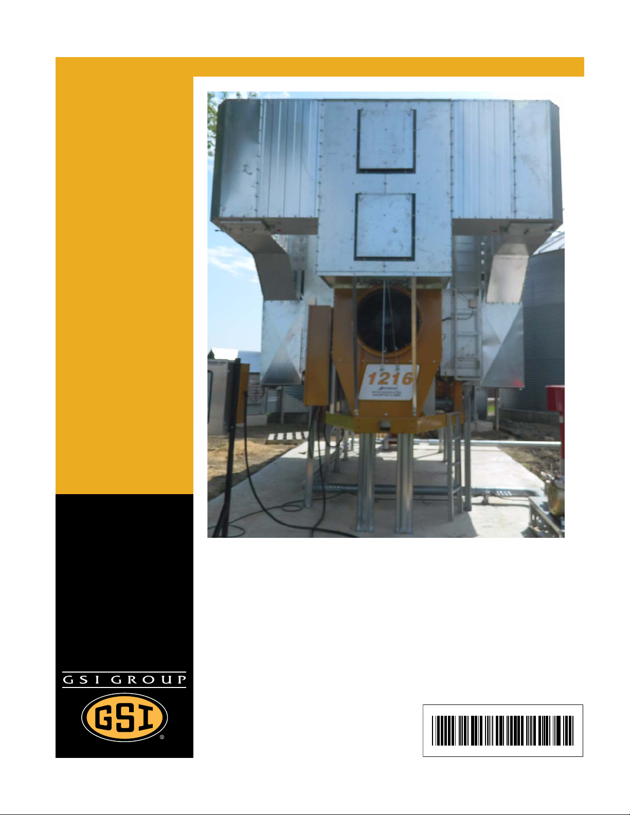
Heat Reclaimer for Single
Module Dryers
Assembly Manual
PNEG-361
Date: 12-19-12
Page 2

2 PNEG-361 Heat Reclaimer for Single Module Dryers
Page 3

Table of Contents
Contents
Chapter 1 Safety ..................................................................................................................................................... 4
Safety Guidelines .................................................................................................................................. 4
General Safety Statement ..................................................................................................................... 5
Safety Instructions ..................... ... .... .......................................... ... ........................................................ 6
Chapter 2 Assembly Instructions ......................... .................................................... ............................................ 8
General Notes ....................................................................................................................................... 8
Hardware Notes .................................................................................................................................... 8
Inlet Box Assembly Instructions .......................................................................................................... 10
Column Assembly Instructions ............................................................................................................ 22
Transition Duct Assembly Instructions ................................................................................................ 28
Air Access Door Assembly Instructions .............................................................................................. 44
Chapter 3 Warranty .............................................................................................................................................. 45
PNEG-361 Heat Reclaimer for Single Module Dryers 3
Page 4
1. Safety
This is the safety alert symbol. It is used to alert you
to potential personal injury hazards. Obey all safety
messages that follow this symbol to avoid possible
injury or death.
WARNING indicates a hazardous situation which, if not
avoided, could result in death or serious injury.
CAUTION, used with the safety alert symbol, indicates a
hazardous situation which, if not avoided, could result in
minor or moderate injury.
NOTICE is used to address practices not related to
personal injury.
DANGER indicates a hazardous situation which, if not
avoided, will result in death or serious injury.
Safety Guidelines
This manual contains information that is important for you, the owner/operator, to know and understand.
This information relates to protecting personal safety and preventing equipment problems. It is the
responsibility of the owner/operator to inform anyone operating or working in the area of this equipment
of these safety guidelines. To help you recognize this information, we use the symbols that are defined
below. Please read the manual and pay attention to these sections. Failure to read this manual and its
safety instructions is a misuse of the equipment and may lead to serious injury or death.
DANGER
WARNING
CAUTION
NOTICE
4 PNEG-361 Heat Reclaimer for Single Module Dryers
Page 5

1. Safety
This product has sharp edges, which may cause serious injury. To avoid injury, handle
sharp edges with caution and always use proper protective clothing and equipment.
General Safety Statement
Our foremost concern is your safety and the safety of others associated with grain handling equipment.
This manual is to help you understand safe operating procedures and some problems that may be
encountered by the operator and other personnel.
As owner and/or operator, you are responsible to know what requirements, hazard s, and precautions exist
and inform all personnel associated with the equipment or in the area. Safety precautions may be required
from the personnel. Avoid any alterations to the equipment, which may produce a very dangerous
situation, where SERIOUS INJURY or DEATH may occur.
You should consider the location of the bin site relative to power line locations or electrical transmission
equipment. Contact your local power company to review your installation plan or for information
concerning required equipment clearance. Clearance of portable equipment that may be taken to the bin
site should also be reviewed and considered. Any electrical control equipment in contact with the bin
should be properly grounded and installed in accordance with National Electric Code provisions and other
local or national codes.
This product is intended for the use of grain storage only. Any other use is a misuse of the product.
Sidewall bundles or sheets must be stored in a safe manner. The safest method of storing sidewall
bundles is laying horizontally with the arch of the sheet upward, like a dome. Sidewall sheets stored on
edge must be secured so that they cannot fall over and cause injury. Use care when handling and moving
sidewall bundles.
Personnel operating or working around equipment should read this manual. This manual must be
delivered with equipment to its owner. Failure to read this manual and its safety instructions is a
misuse of the equipment.
PNEG-361 Heat Reclaimer for Single Module Dryers 5
Page 6
1. Safety
Follow Safety Instructions
Carefully read all safety messages in this manual and
safety signs on your machine. Keep signs in good
condition. Replace missing or damaged safety signs. Be
sure new equipment components and repair parts include
the current safety signs. Replacement safety signs are
available from the manufacturer.
Learn how to operate the machine and how to use controls
properly. Do not let anyone operate without instruction.
Keep your machinery in proper working condition.
Unauthorized modifications to the machine may impair
the function and/or safety and affect machine life.
If you do not understand any part of this manual or need
assistance, contact your dealer.
Read and Understand Manual
Practice Safe Maintenance
Understand service procedures before doing work. Keep area
clean and dry.
Never lubricate, service, or adjust machine while it is in operation.
Keep hands, feet and clothing away from rotating parts.
Keep all parts in good condition and properly installed. Fix
damage immediately . Replace worn or broken p arts. Remove any
built-up grease, oil, and debris.
Maintain Equipment
and Work Area
Safety Instructions
Our foremost concern is your safety and the safety of others associated with this equipment. We want to
keep you as a customer. This manual is to help you understand safe operating procedures and some
problems that may be encountered by the operator and other personnel.
As owner and/or operator, it is your responsibility to know what requirements, hazards, and precautions
exist, and to inform all personnel associated with the equipment or in the area. Safety precautions may be
required from the personnel. Avoid any alterations to the equipment. Such alterations may p roduce a very
dangerous situation where SERIOUS INJURY or DEATH may occur.
This equipment shall be installed in accordance with the current installation codes and applicable
regulations, which should be carefully followed in all cases. Authorities having jurisdiction should be
consulted before installations are made.
6 PNEG-361 Heat Reclaimer for Single Module Dryers
Page 7
1. Safety
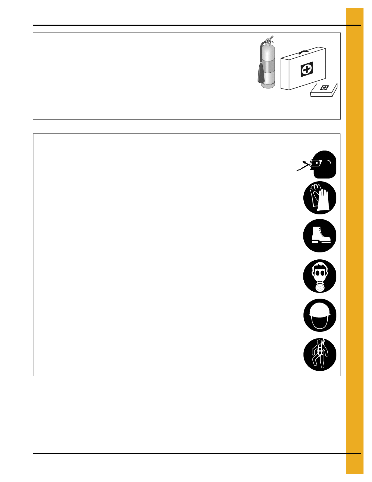
Prepare for Emergencies
Be prepared if fire starts.
Keep a first aid kit and fire extinguisher handy.
Keep emergency numbers for doctors, ambulance service,
hospital, and fire department near your telephone.
Keep Emergency Equipment
Quickly Accessible
Wear Protective Clothing
Wear close-fitting clothing and safety equipment appropriate
to the job.
Remove all jewelry.
Tie long hair up and back.
Wear safety glasses at all times to protect eyes from debris.
Wear gloves to protect your hands from sharp edges on
plastic or steel parts.
Wear steel-toed boots to help protect your feet from falling
debris. Tuck in any loose or dangling shoestrings.
A respirator may be needed to prevent breathing potentially
toxic fumes and dust.
Wear a hard hat to help protect your head.
Wear appropriate fall protection equipment when working at
elevations greater than six feet (6').
Eye Protection
Gloves
Steel-Toed Boots
Respirator
Hard Hat
Fall Protection
PNEG-361 Heat Reclaimer for Single Module Dryers 7
Page 8

2. Assembly Instructions
General Notes
The Heat Reclaimer package has been designed to reduce the amount of heat loss to the atmosphere and
to recycle this heat in order to help reduce fuel consumption.
Hardware Notes
All Heat Reclaimer components should be bolted together using 5/16"-18 x 3/4" ZN grade 5 flange bolts
(S-6606) and 5/16"-18 YDP grade 2 flange nuts (S-3611) in the Heat Reclaimer hardware package.
8 PNEG-361 Heat Reclaimer for Single Module Dryers
Page 9

Inlet Box Assembly
Instructions
PNEG-361 Heat Reclaimer for Single Module Dryers 9
Page 10
2. Assembly Instructions
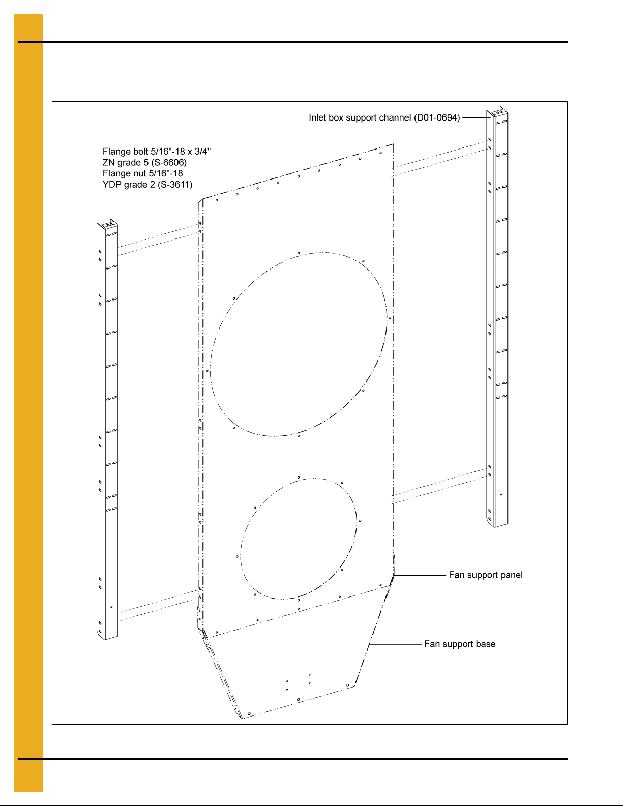
Inlet Box Assembly Instructions
1. Assemble inlet box support channel (D01-0694) with panel and fan support base. (See Figure 2A.)
Figure 2A
10 PNEG-361 Heat Reclaimer for Single Module Dryers
Page 11
2. Assembly Instructions
Inlet Box Assembly Instructions (Continued)
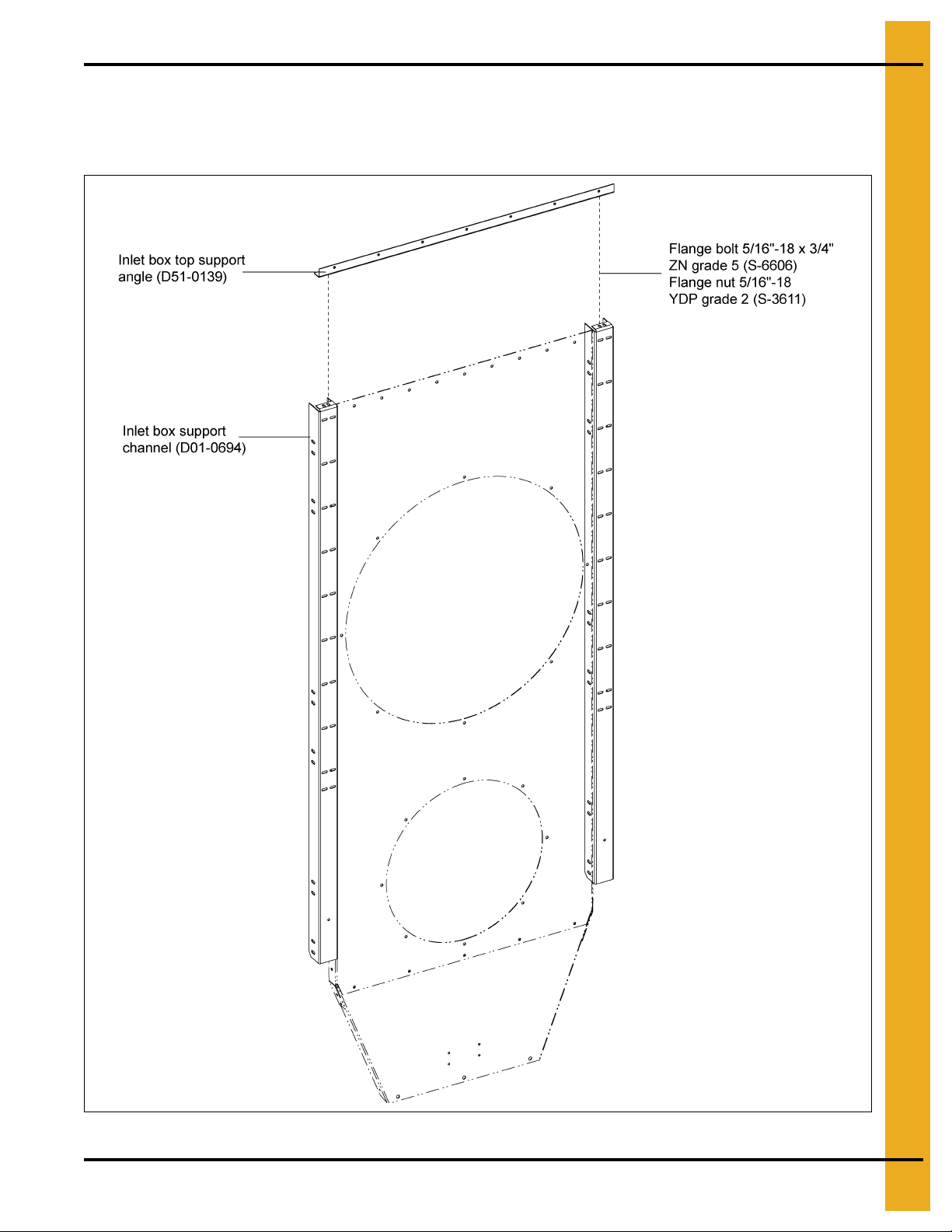
2. Assemble inlet box top support angle (D51-0139) with inlet box support channel (D01-0694).
(See Figure 2B.)
Figure 2B
PNEG-361 Heat Reclaimer for Single Module Dryers 11
Page 12
2. Assembly Instructions
Inlet Box Assembly Instructions (Continued)
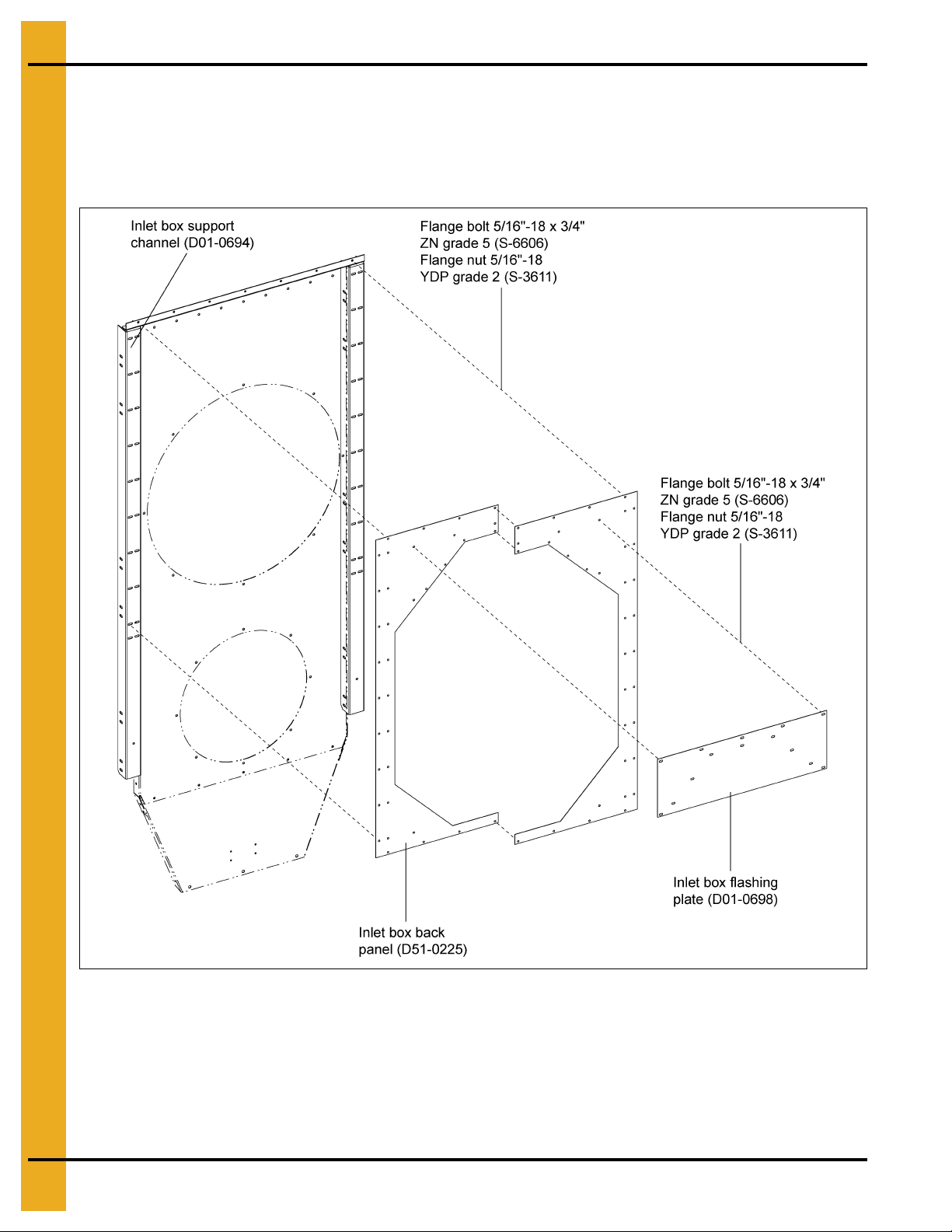
3. Assemble combination of inlet box back panels (D51-0225) with inlet box support channel
(D01-0694). (See Figure 2C.)
Assemble inlet box flashing plate (D01-0698) with inlet box back panels (D51-0225).
Figure 2C
12 PNEG-361 Heat Reclaimer for Single Module Dryers
Page 13
2. Assembly Instructions
Inlet Box Assembly Instructions (Continued)
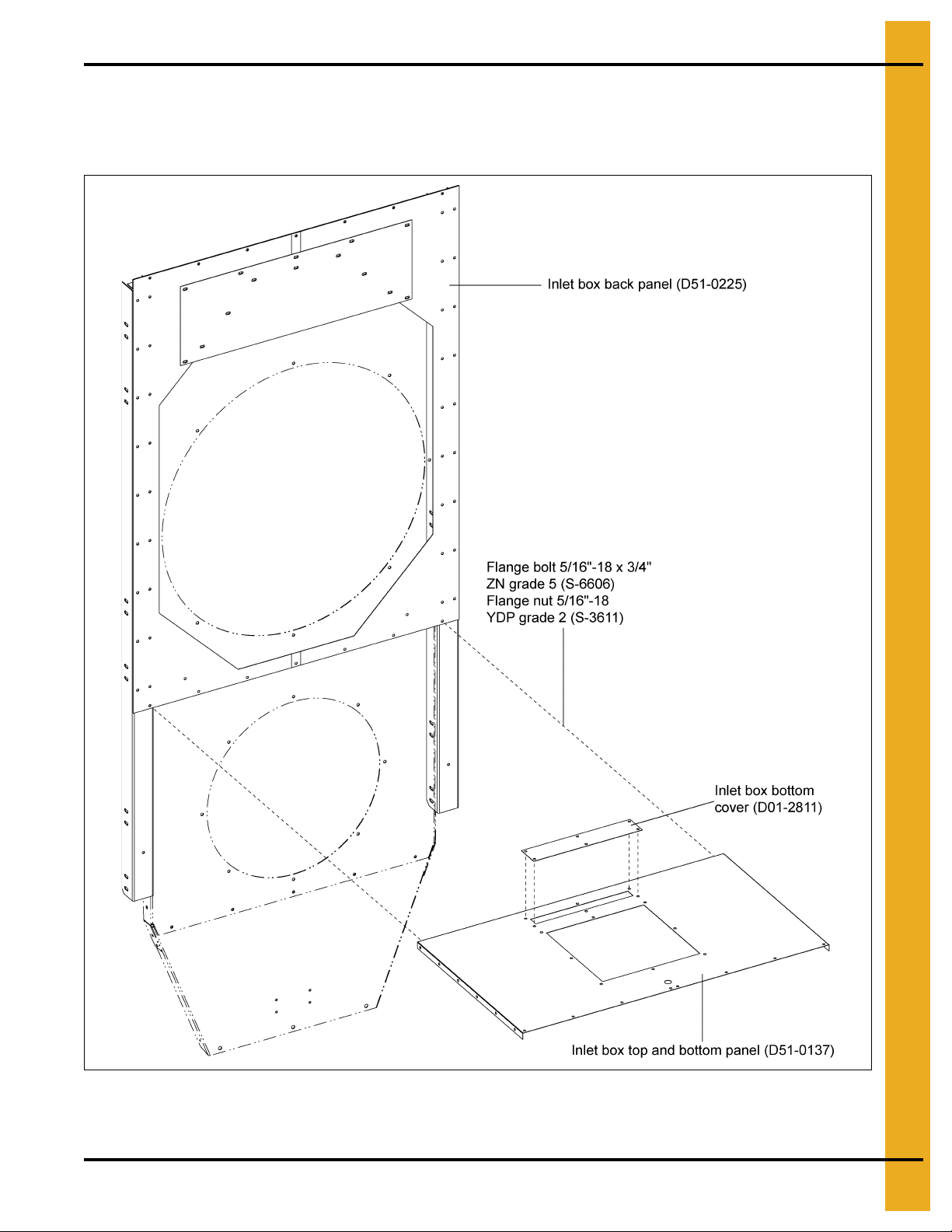
4. Assemble combination of inlet box bottom cover (D01-2811) and inlet box bo ttom panel (D51-0137)
with inlet box back panels (D51-0225). (See Figure 2D.)
Figure 2D
PNEG-361 Heat Reclaimer for Single Module Dryers 13
Page 14
2. Assembly Instructions
Inlet Box Assembly Instructions (Continued)
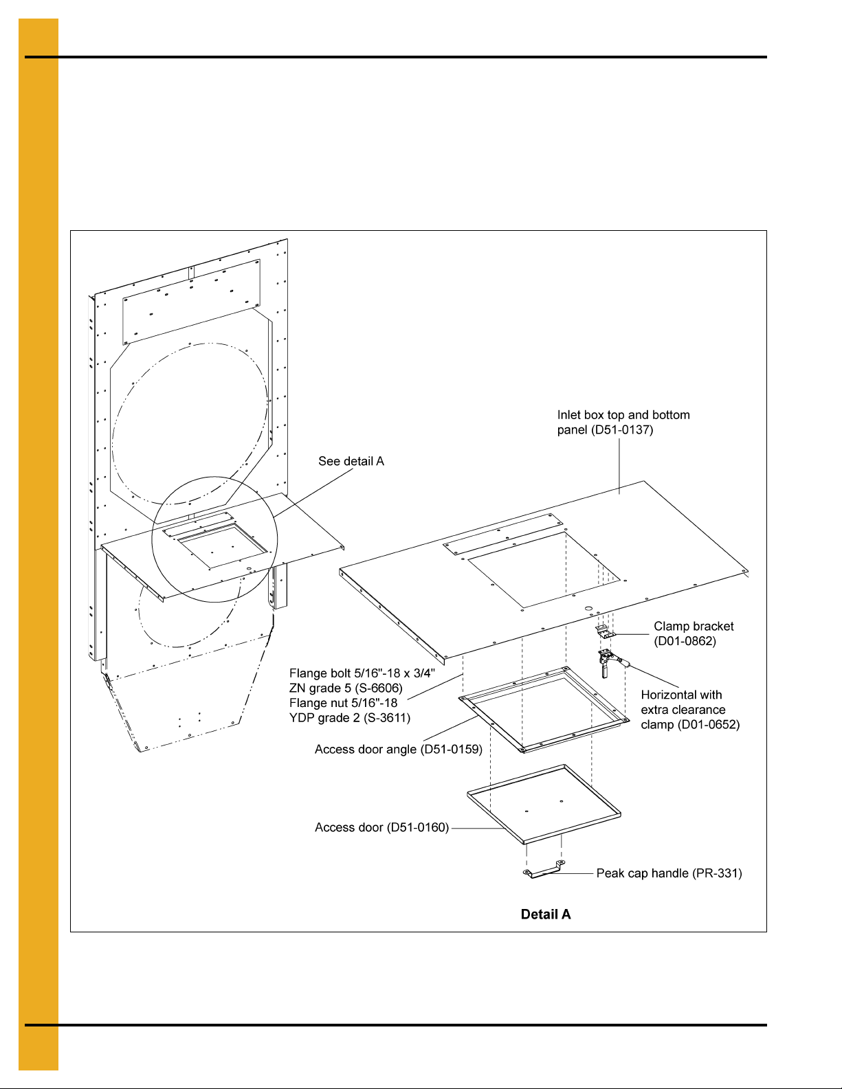
5. Assemble access door angles (D51-0159) with inlet box bottom panel (D51-0137). (See Figure 2E.)
Assemble combination of access door (D51-0160) and peak cap handle (PR-331) with access door
angles (D51-0159).
Assemble combination of clamp bracket (D01-0862) and clamp (D01-0652) with inlet box bottom
panel (D51-0137).
Figure 2E
14 PNEG-361 Heat Reclaimer for Single Module Dryers
Page 15

2. Assembly Instructions
Inlet Box Assembly Instructions (Continued)
6. Assemble combination of R.H. and L.H. inlet box front panel (D51-0144 and D51 -0230) with inlet box
bottom panel (D51-0137). (See Figure 2F.)
Assemble two (2) front panel angles (D51-0161) with R.H. and L.H. inlet box front panel (D51-0144
and D51-0230).
Assemble front support angle (D51-0153) with inlet box bottom panel (D51-0137).
Figure 2F
PNEG-361 Heat Reclaimer for Single Module Dryers 15
Page 16

2. Assembly Instructions
Inlet Box Assembly Instructions (Continued)
7. Assemble inlet box top panel (D51-0163) with both inlet box front and back panels. (See Figure 2G.)
Figure 2G
16 PNEG-361 Heat Reclaimer for Single Module Dryers
Page 17

2. Assembly Instructions
Inlet Box Assembly Instructions (Continued)
8. Assemble R.H. inlet box panel (D01-0883) with R.H. inlet box front panel (D51-0144).
Assemble L.H. inlet box panel (D01-0882) with L.H. inlet box front panel (D51-0230).
(See Figure 2H.)
Figure 2H
PNEG-361 Heat Reclaimer for Single Module Dryers 17
Page 18

2. Assembly Instructions
Inlet Box Assembly Instructions (Continued)
9. Assemble R.H. inlet box panel (D01-0883) with L.H. inlet box front panel (D51-0230).
Assemble L.H. inlet box panel (D01-0882) with R.H. inlet box front panel (D51-0144).
(See Figure 2I.)
Figure 2I
18 PNEG-361 Heat Reclaimer for Single Module Dryers
Page 19

2. Assembly Instructions
Inlet Box Assembly Instructions (Continued)
10. Front surface brace (D51-0154), top hole assemble with front support angle (D51-0153) and bottom
hole assemble with fan support base. (See Figure 2J.)
Figure 2J
PNEG-361 Heat Reclaimer for Single Module Dryers 19
Page 20

2. Assembly Instructions
Inlet Box Assembly Instructions (Continued)
11. Front surface brace (D01-2827), top hole assemble with front support angle (D51-0153) and bottom
hole assemble with fan support base. (See Figure 2K.) NOTE: Inlet box bottom panel cover
(D01-2811) is not used.
Figure 2K
20 PNEG-361 Heat Reclaimer for Single Module Dryers
Page 21

Column Assembly Instructions
PNEG-361 Heat Reclaimer for Single Module Dryers 21
Page 22

2. Assembly Instructions
Column Assembly Instructions
1. Assemble combination of L.H. bottom rear end panel (D51-0172) and column panel bracket
(D51-0171) with column end panel L.H. rear grain dryers (D01-2477). (See Figure 2L.)
Assemble combination of R.H. bottom rear end panel (D51-0117) and column panel bracket
(D51-0171) with column end panel R.H. rear grain dryers (D01-2476).
Figure 2L
22 PNEG-361 Heat Reclaimer for Single Module Dryers
Page 23

2. Assembly Instructions
Column Assembly Instructions (Continued)
2. Assemble lower inner panel (D61-0248) and with L.H. bottom rear end panel (D51-0172).
Assemble lower inner panel (D61-0248) and with R.H. bottom rear end panel (D51-0117).
(See Figure 2M.)
Figure 2M
PNEG-361 Heat Reclaimer for Single Module Dryers 23
Page 24

2. Assembly Instructions
Column Assembly Instructions (Continued)
3. Assemble column panel (D51-0118) with R.H. bottom rear end panel (D51-0117).
Assemble column panel (D51-0118) with L.H. bottom rear end panel (D51-0112). (See Figure 2N.)
Figure 2N
24 PNEG-361 Heat Reclaimer for Single Module Dryers
Page 25

2. Assembly Instructions
Column Assembly Instructions (Continued)
4. Assemble combination of horizontal support angle (D51-0126) and column panel brace (D51-0127)
with between the columns panels (D51-0118). (See Figure 2O.)
Figure 2O
PNEG-361 Heat Reclaimer for Single Module Dryers 25
Page 26

NOTES
26 PNEG-361 Heat Reclaimer for Single Module Dryers
Page 27

Transition Duct Assembly
Instructions
PNEG-361 Heat Reclaimer for Single Module Dryers 27
Page 28

2. Assembly Instructions
Transition Duct Assembly Instructions
1. Once all column panels are assembled, assemble transition rear end panel (D51-0189) with column
panel (D51-0118). (See Figure 2P.)
Figure 2P
28 PNEG-361 Heat Reclaimer for Single Module Dryers
Page 29

2. Assembly Instructions
Transition Duct Assembly Instructions (Continued)
2. Assemble transition vent panels (D51-0187) with transition rear end panel (D51-0189).
(See Figure 2Q.)
Figure 2Q
PNEG-361 Heat Reclaimer for Single Module Dryers 29
Page 30

2. Assembly Instructions
Transition Duct Assembly Instructions (Continued)
3. Assemble R.H. small transition panel (D51-0183) and R.H. large upper transition panel (D51-0180)
with transition vent panel (D51-0187).
Assemble L.H. small transition panel (D51-0182) and L.H. large upper transition panel (D51-0181)
with transition vent panel (D51-0187). (See Figure 2R.)
Figure 2R
30 PNEG-361 Heat Reclaimer for Single Module Dryers
Page 31

2. Assembly Instructions
Transition Duct Assembly Instructions (Continued)
4. Assemble transition roof panel (D51-0184) with both R.H. small transition panel (D51-0183) and
R.H. large upper transition panel (D51-0180). (See Figure 2S.)
Figure 2S
PNEG-361 Heat Reclaimer for Single Module Dryers 31
Page 32

2. Assembly Instructions
Transition Duct Assembly Instructions (Continued)
5. Assemble R.H. small outer transition panel (D51-0202) and R.H. large outer transition panel
(D51-0200) with transition roof panel (D51-0184).
Assemble L.H. small outer transition panel (D51-0201) and L.H. large outer transition panel
(D51-0199) with transition roof panel (D51-0184). (See Figure 2T.)
Figure 2T
32 PNEG-361 Heat Reclaimer for Single Module Dryers
Page 33

2. Assembly Instructions
Transition Duct Assembly Instructions (Continued)
6. Assemble L.H. front end transition panel (D51-0188) with R.H. large outer transition panel (D51-0200).
Assemble R.H. front end transition panel (D51-0190) with L.H. large outer transition panel
(D51-0199). (See Figure 2U.)
Figure 2U
PNEG-361 Heat Reclaimer for Single Module Dryers 33
Page 34

2. Assembly Instructions
Transition Duct Assembly Instructions (Continued)
7. Assemble combination of transition duct (D51-0211) and side duct panel (D51-0212) with R.H. large
upper transition panel (D51-0180).
Assemble combination of transition duct (D51-0210) and side duct panel (D51-0212) with L.H. large
upper transition panel (D51-0181). (See Figure 2V.)
Figure 2V
34 PNEG-361 Heat Reclaimer for Single Module Dryers
Page 35

2. Assembly Instructions
Transition Duct Assembly Instructions (Continued)
8. Assemble side duct bottom (D51-0214) with both transition duct (D51-0211) and side duct
panel (D51-0212).
Assemble side duct bottom (D51-0214) with both transition duct (D51-0210) and side duct panel
(D51-0212). (See Figure 2W.)
Figure 2W
PNEG-361 Heat Reclaimer for Single Module Dryers 35
Page 36

2. Assembly Instructions
Transition Duct Assembly Instructions (Continued)
9. Assemble combination of transition duct (D51-0210) and side duct panel (D51-0212) with side duct
bottom (D51-0214).
Assemble combination of transition duct (D51-0211) and side duct pan el (D51-0212 ) wit h side du ct
bottom (D51-0214). (See Figure 2X.)
Figure 2X
36 PNEG-361 Heat Reclaimer for Single Module Dryers
Page 37

2. Assembly Instructions
Transition Duct Assembly Instructions (Continued)
10. Assemble side duct top (D51-0213) with transition roof panel (D51-0184). (See Figure 2Y.)
Figure 2Y
PNEG-361 Heat Reclaimer for Single Module Dryers 37
Page 38
2. Assembly Instructions
Transition Duct Assembly Instructions (Continued)
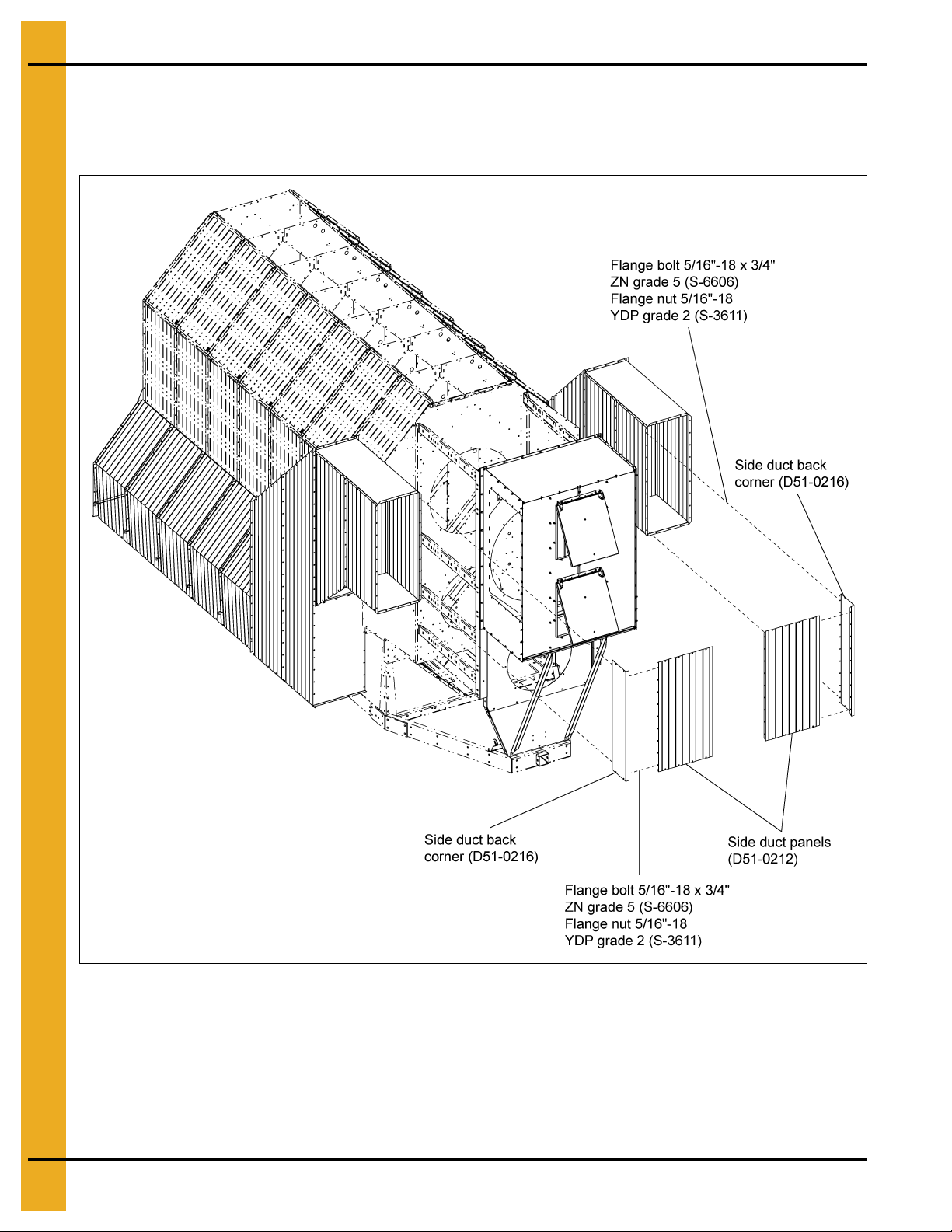
11. Assemble combination of side duct back corner (D51-0216) and side duct panel (D51-0212) with side
duct panel (D51-0212). (See Figure 2Z.)
Figure 2Z
38 PNEG-361 Heat Reclaimer for Single Module Dryers
Page 39

2. Assembly Instructions
Transition Duct Assembly Instructions (Continued)
12. Assemble L.H. side duct corner bottom (D51-0217) with L.H. inlet box panel (D51-0882).
Assemble R.H. side duct corner bottom (D51-0218) with R.H. inlet box panel (D51-0883).
Assemble access door angles (D51-0159) with L.H. side duct corner bottom (D51-0217).
Assemble combination of access door (D51-0160) and peak cap handle (PR-331) with access door
angles (D51-0159).
Assemble combination of clamp bracket (D01-0862) and clamp (D01-0652) with L.H. side duct
corner bottom (D51-0217). (See Figure 2AA.)
Figure 2AA
PNEG-361 Heat Reclaimer for Single Module Dryers 39
Page 40

2. Assembly Instructions
Transition Duct Assembly Instructions (Continued)
13. Assemble side duct panel (D51-0212) with L.H. side duct corner bottom (D51-0217).
Assemble side duct panel (D51-0212) with R.H. side duct corner bottom (D51-0218).
(See Figure 2AB.)
Figure 2AB
40 PNEG-361 Heat Reclaimer for Single Module Dryers
Page 41

2. Assembly Instructions
Transition Duct Assembly Instructions (Continued)
14. Assemble combination of side duct front corner (D51-0215) and side duct panel (D51-0212) with R.H.
inlet box panel (D01-0883).
Assemble combination of side duct front corner (D51-0215) and side duct panel (D51-0212) with L.H.
inlet box panel (D01-0882). (See Figure 2AC.)
Figure 2AC
PNEG-361 Heat Reclaimer for Single Module Dryers 41
Page 42

2. Assembly Instructions
Transition Duct Assembly Instructions (Continued)
15. Assemble R.H. side duct corner top (D51-0220) with R.H. inlet box panel (D01-0883).
Assemble L.H. side duct corner top (D51-0219) with L.H. inlet box panel (D01-0882).
(See Figure 2AD.)
Figure 2AD
42 PNEG-361 Heat Reclaimer for Single Module Dryers
Page 43

Air Access Door Assembly
Instructions
PNEG-361 Heat Reclaimer for Single Module Dryers 43
Page 44

2. Assembly Instructions
Air Access Door Assembly Instructions
1. Mount the operator’s door hinges (D31-0296 and D31-0297) to the square rear access door using the
nuts and bolts. Mount the door to the hinge bracket using the 5/16" bolts and nuts.
(See Figure 2AE.)
Figure 2AE
44 PNEG-361 Heat Reclaimer for Single Module Dryers
Page 45

3. Warranty
9101239_1_CR_rev7.DOC (revised July 2009)
GSI Group, LLC Limited Warranty
The GSI Group, LLC (“GSI”) warrants products which it manufactures to be free of defects in materials and workmanship
under normal usage and conditions for a period of 12 months after sale to the original end-user or if a foreign sale,
14 months from arrival at port of discharge, whichever is earlier. The end-user’s sole remedy (and GSI’s only obligation)
is to repair or replace, at GSI’s option and expense, products that in GSI’s judgment, contain a material defect in materials
or workmanship. Expenses incurred by or on behalf of the end-user without prior written authorization from the GSI
Warranty Group shall be the sole responsibility of the end-user.
Warranty Extensions:
The Limited Warranty period is extended for the following products:
Product Warranty Period
Performer Series Direct Drive Fan Motor 3 Years
AP Fans and Flooring
Cumberland
Feeding/Watering
Systems
Grain Systems Grain Bin Structural Design 5 Years
Grain Systems
Farm Fans
Zimmerman
All Fiberglass Housings Lifetime
All Fiberglass Propellers Lifetime
Feeder System Pan Assemblies 5 Years **
Feed Tubes (1-3/4" and 2.00") 10 Years *
Centerless Augers 10 Years *
Watering Nipples 10 Years *
Portable and Tower Dryers 2 Years
Portable and Tower Dryer Frames and
Internal Infrastructure †
5 Years
* Warranty prorated from list price:
0 to 3 years - no cost to end-user
3 to 5 years - end-user pays 25%
5 to 7 years - end-user pays 50%
7 to 10 years - end-user pays 75%
** Warranty prorated from list price:
0 to 3 years - no cost to end-user
3 to 5 years - end-user pays 50%
† Motors, burner components
and moving parts not included.
Portable dryer screens included.
Tower dryer screens not included.
GSI further warrants that the portable and tower dryer frame and basket, excluding all auger and auger drive components,
shall be free from defects in materials for a period of time beginning on the twelfth (12
and continuing until the sixtieth (60
th
) month from the date of purchase (extended warranty period). During the extended
th
) month from the date of purchase
warranty period, GSI will replace the frame or basket components that prove to be defective under normal conditions
of use without charge, excluding the labor, transportation, and/or shipping costs incurred in the performance of this
extended warranty.
Conditions and Limitations:
THERE ARE NO WARRANTIES THAT EXTEND BEYOND THE LIMITED WARRANTY DESCRIPTION SET FORTH
ABOVE. SPECIFICALLY, GSI MAKES NO FURTHER WARRANTY OF ANY KIND, EXPRESS OR IMPLIED,
INCLUDING, WITHOUT LIMITATION, WARRANTIES OF MERCHANTABILITY OR FITNESS FOR A PARTICULAR
PURPOSE OR USE IN CONNECTION WITH: (I) PRODUCT MANUFACTURED OR SOLD BY GSI OR (II) ANY ADVICE,
INSTRUCTION, RECOMMENDATION OR SUGGESTION PROVIDED BY AN AGENT, REPRESENTA TIVE OR
EMPLOYEE OF GSI REGARDING OR RELATED TO THE CONFIGURATION, INSTALLATION, LAYOUT, SUITABILITY
FOR A PARTICULAR PURPOSE, OR DESIGN OF SUCH PRODUCTS.
GSI shall not be liable for any direct, indirect, incidental or consequential damages, including, without limitation, loss of
anticipated profits or benefits. The sole and exclusive remedy is set forth in the Limited Warranty, which shall not exceed
the amount paid for the product purchased. This warranty is not transferable and applies only to the original end-user. GSI
shall have no obligation or responsibility for any representations or warranties made by or on behalf of any dealer, agent
or distributor.
GSI assumes no responsibility for claims resulting from construction defects or unauthorized modifications to products
which it manufactured. Modifications to products not specifically delineated in the manual accompanying the equipment at
initial sale will void the Limited Warranty.
This Limited Warranty shall not extend to products or parts which have been damaged by negligent use, misuse, alteration,
accident or which have been improperly/inadequately maintained. This Limited Warranty extends solely to products
manufactured by GSI.
Prior to installation, the end-user has the responsibility to comply with federal, state and local codes which apply to the
location and installation of products manufactured or sold by GSI.
PNEG-361 Heat Reclaimer for Single Module Dryers 45
Page 46

This equipment shall be installed in accordance with
the current installation codes and applicable
regulations, which should be carefully followed in all
cases. Authorities having jurisdiction should be
consulted before installations are made.
Copyright © 2012 by GSI Group
Printed in the USA
GSI Group
1004 E. Illinois St.
Assumption, IL 62510-0020
Phone: 1-217-226-4421
Fax: 1-217-226-4420
www.gsiag.com
CN-301203
 Loading...