

Page 1
revised 2004revised 2004
revised 2004
revised 2004revised 2004
SERVICE PLATFORM &
STIFFENER INSTALLATION
PNEG-349REV
TWO & THREE
MODULE STACK DRYER
MODELS
Page 2

Service Platform & Stiffener
2
Page 3

Service Platform & Stiffener
Installation & Safety..............................................................................................4
Service Platform Installation..................................................................................5
Platform Support Channels..............................................................................6
Floor Support Angles.......................................................................................11
Inner Guard Rail...............................................................................................12
Outer Guard Rail Supports...............................................................................12
Platform Toe Board Angles And Flooring.......................................................13
Platform Guard Rails.......................................................................................17
Access Door.....................................................................................................18
Service Platform Parts......................................................................................22
Stiffener Installation..............................................................................................25
Stiffener Basket Location...............................................................................26
Stiffener Exploded View................................................................................27
TABLE OF CONTENTS
Stiffener Assembly.........................................................................................28
Special Buttress Assembly Instructions..........................................................29
Warranty..............................................................................................................30
3
Page 4
INSTALLATION & SAFETY
Service Platform and Stiffener Installation
Service Platform & Stiffener
Thank you for choosing a GSI product. It is designed
to be a reliable support system for GSI grain dryers.
This manual describes the installation of the GSI
platform and GSI stiffener package. These systems
are designed for multi-module grain dryers, and accommodate different dryer lengths.
The principal concern of the GSI Group, Inc.
("GSI") is your safety and the safety of others associated with grain handling equipment. This manual
is written to help you understand safe installation
Safety Alert Symbol
The symbol shown is used to call
your attention to instructions concerning your personal safety.
Watch for this symbol; it points
out important safety precautions.
It means "ATTENTION",
"WARNING", "CAUTION", and
"DANGER". Read the message
and be cautious to the possibility of personal injury or death.
procedures, and some of the problems that may
be encountered by the operator or other personnel.
As owner and/or operator, it is your responsibility to know what requirements, hazards and
precautions exist, and to inform all personnel associated with the equipment, or who are in the
area. Avoid any alterations to the equipment.
Such alterations may produce a very dangerous
situation, where serious injury or death may occur.
WARNING! BE ALERT!
Personnel operating or working
around equipment should read this
manual. This manual must be delivered with the equipment to its owner.
Failure to read this manual and its
safety instructions is a misuse of the
equipment.
Stiffener caption.
4
Page 5
Service Platform & Stiffener
PLATFORM INSTALLATION
5
Page 6
PLATFORM INSTALLATION
Service Platform & Stiffener
Platform Support
Channels
Airstream service platform units are
designed for use with Airstream two
and three module grain dryers. The
two module models require a service
platform on the upper module, and
the three module units use a platform
on both the upper and center mod-
ules.
For ease of assembly, the plat-
form should be fully installed before
the module is lifted and installed.
Install the platform support
channels and related parts within the
platform package number one as fol-
lows:
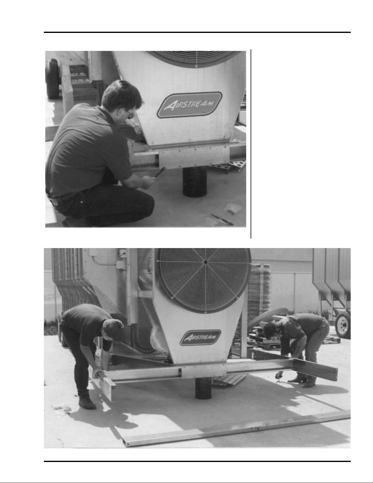
1. If required, connect a platform
attachment bracket, D61-0054,
onto each side of the dryer as
shown. Using the existing large
bolts through the round set of
bracket holes.
Loosely connect the two
rear anchor channels, D61-0055,
to the platform attach brackets us-
ing 3/8" x 1" bolts with washers.
Figure 1, Right:
Connecting rear
anchor chan-
nels. Figure 2,
Below: Mount-
ing the main
support channel.
2. Remove hitch tongue from the
dryer, and support the front end
of the dryer under the frame side
rails.
Loosely connect the main
support channel, D01-2033, to
the front end of the dryer hitch
weldment. Use four 1/2" x
1- 1/2" bolts with washers on slot
ted side. The channel side with
the large round holes must be
up.
6
Page 7
Service Platform & Stiffener
PLATFORM INSTALLATION
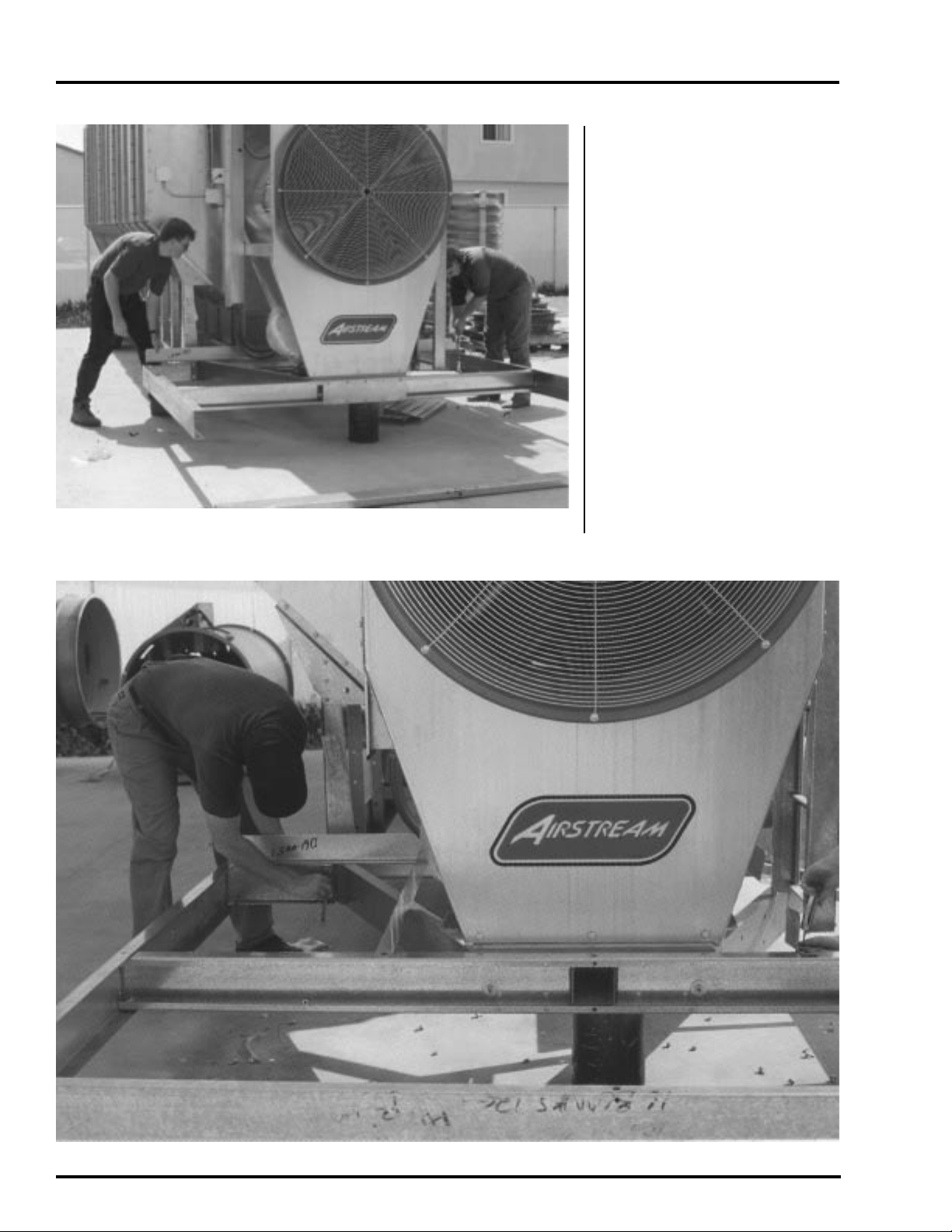
3. Attach the D61-0056 reinforce-
ment plate to the main floor sup-
port channel using 5/16" x 3/4"
whiz bolts.
4. Position the left-hand side chan-
nel, D61-0058, and the right-
hand side channel, D61-0057,
so the sides with the dimpled
holes are up. Connect them to
the rear anchor channels and
the main support channel. Use
the special 5/16" diameter flat
head allen capscrews to secure
the top side of the two side chan-
nels. Use 5/16" x 3/4" bolts at
the bottom side.
Figure 3: Bolting reinforcement plate to main support channel.
Figure 4: Attaching side channels.
7
Page 8
PLATFORM INSTALLATION
Service Platform & Stiffener
5. Position the rear angle tie, D01-
2034, and connect it onto the
rear anchor channels using
5/16" x 1" carriage head bolts.
6. Position the front channel, D61-
0061, so the side with the large
holes is up and connect it to
the two side channels. Use flat-
head allen capscrews to secure
the top side.
Figure 5: Placing rear tie angle on platform.
Figure 6: Tighten the rear frame tie angle to the side frame.
8
Page 9
Service Platform & Stiffener
PLATFORM INSTALLATION
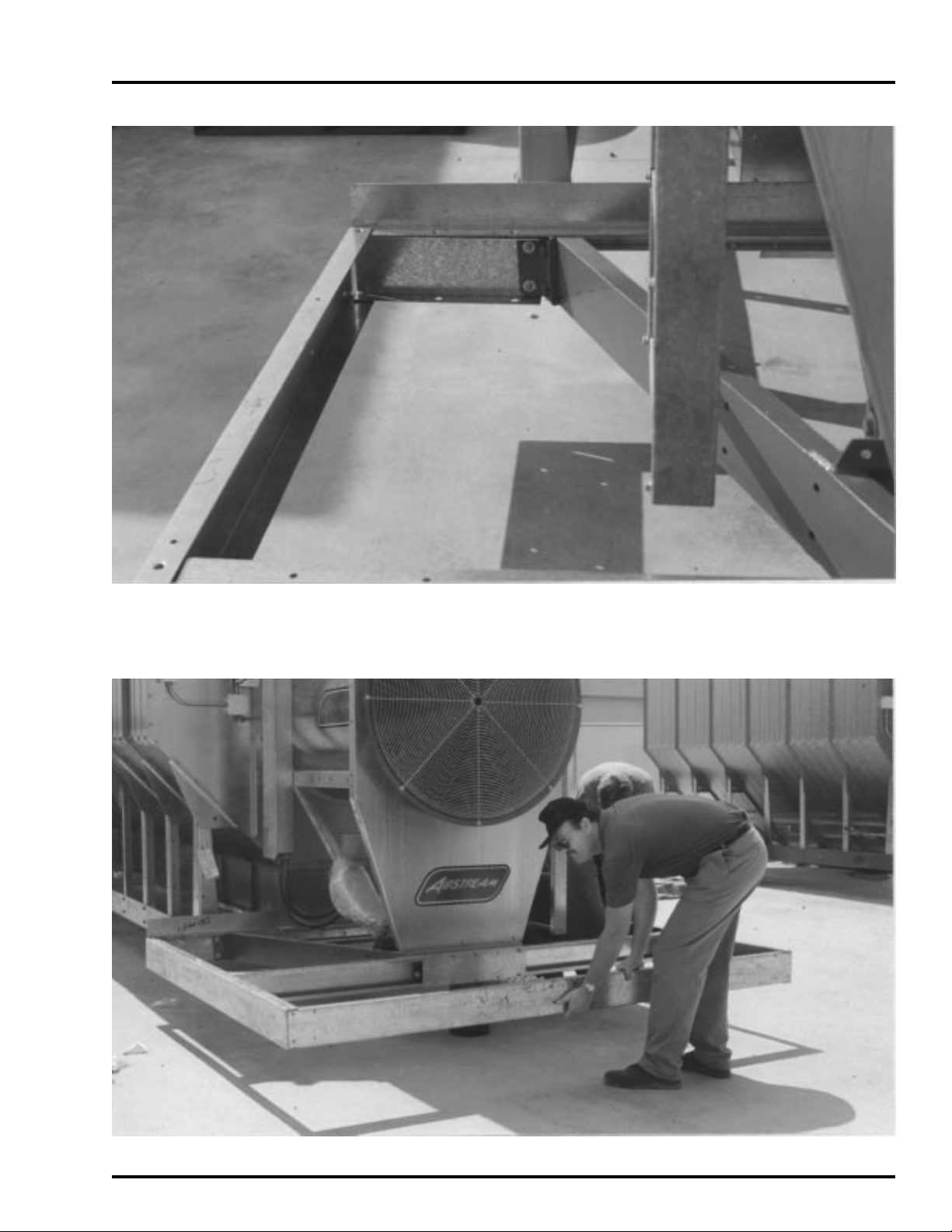
Figure 7: Close-up of rear portion of frame.
Figure 8: Attaching front channel.
9
Page 10
PLATFORM INSTALLATION
7. Use two flathead allen capscrews
and connect the center floor
support, D61-0062, to the front
and main support channels.
8. Use a carpenter square and
check the squareness of the as-
sembled unit, between the main
channel and the side channels.
If necessary, shift the position
of the main channel slightly, us-
ing the slotted attaching holes,
until the unit is properly
squared. Then fully tighten all
channel bolts.
Service Platform & Stiffener
Figure 9: Center floor support placement.
10
Figure 10: Check for square and tighten bolts.
Page 11

Service Platform & Stiffener
Floor Support Angles
Install the floor support angles
as follows:
1. Use two flathead allen capscrews
and connect the left floor sup-
port angle, D01-2030, to the
rear angle tie and main sup-
port channel.
2. Connect the rear access door
support, D01-2037, frame be
tween the support angle and the
left-hand side channel.
PLATFORM INSTALLATION
3. Install the front access door
support frame, D01-2036, to
the side frame and front left-
hand floor support. Use the 5/
16" whiz bolts and nuts to bolt it in
place.
4. The forward frame goes under the
top edge of the side channel and
over the front left-hand floor sup-
port.
Figure 11: Installing forward frame on the access door.
D01-2030
D01-2037
D01-2036
Figure 12: Close-up of forward and rear door frame installation.
11
Page 12

PLATFORM INSTALLATION
Inner Guard Rail
Install the inner guard rail supports
and related parts within platform
package number two as follows:
1. Connect the right-hand rear in-
ner guard rail support angle (D01-
2041). Use 5/16" x 3/4" bolts.
2. Use 5/16" x 3/4" bolts and con-
nect the left-hand inner guard
rail support angle (D01-2042).
Service Platform & Stiffener
D01-2043
3. Connect a lower inner guard rail
angle on each side (D01-2043).
Outer Guard Rail
Supports
Install outer guard rail support chan-
nels, door hinge channel and floor
panels contained within platform
package number two and number
three as follows:
1. Use 5/16" x 3/4" bolts and loosely
connect the seven guard rail
support channels (D61-0037) to
the platform support channels.
2. Connect the outer door hinge
channel (D61-0066) using 5/16"
x 3/4" bolts.
D01-2042
Figure 13: Location of inner guard rail support angles.
12
Figure 14: Install remaining support channels.
Page 13

Service Platform & Stiffener
PLATFORM INSTALLATION
Platform Toe Board
Angles And Flooring
Use 5/16" x 3/4" bolts and install the
platform floor toe board angles.
When two toe boards are listed, the
bottom toe board must be positioned
to capture the floor panels. The ad-
ditional upper toe board acts as a
narrow foot rail to provide added
safety protection. When connecting
upper toe boards, install bolts so the
head ends are located within the plat-
form. The long flanges of the toe
boards point up.
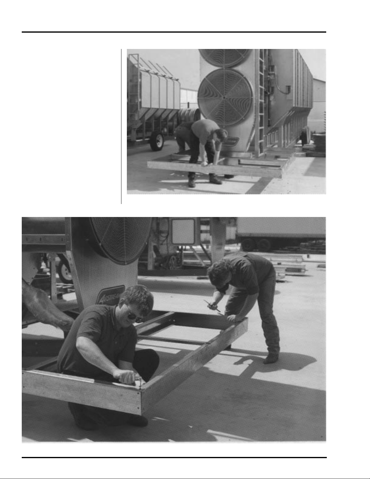
Figure 15: Connecting outer front toe board to guard rail support channels.
Figure 16: Connecting left-hand front toe board to guard rail support channel.
13
Page 14

PLATFORM INSTALLATION
Service Platform & Stiffener
1. Connect one left-hand outer rear
toe boards.
2. Connect the left-hand inner rear
toe board.
3. Connect one left-hand front toe
boards.
4. Connect one right-hand outer toe
boards.
5. Connect one outer front toe boards.
Figure 17: Installing four short floor panels.
14
Figure 18: Installing center long floor panels.
Page 15

Service Platform & Stiffener
PLATFORM INSTALLATION
Figure 19: Installing front long floor panel.
Figure 20: Installing the remaining toe boards.
6. Connect the right-hand inner toe
board.
7. Place the short wide floor pan-
els on the left-hand side of the
platform at the rear.
8. Place the four short floor panels on
the right-hand side at the rear.
9. Place the three long floor panels
across the front end of the platform.
10. Connect the remaining toe boards
around the platform.
15
Page 16

PLATFORM INSTALLATION
Service Platform & Stiffener
16
Figure 21: Installation of the short wide floor panel, left-hand outer rear toeboards and hinge channel.
Page 17

Service Platform & Stiffener
PLATFORM INSTALLATION
Platform Guard Rails
Use 5/16" x 3/4" bolts and install plat-
form guard rails within platform pack-
age # 4. Guard rails should be installed
so that the smooth rail surfaces and
bolt heads are within the compartment
to provide maximum body protection
from corners and angle edges.
1. Connect the upper side guard
rail onto each side.
2. Connect the upper front guard rail.
3. Connect two rear guard rails
onto each rear side of platform.
Figure 22, top: Installing front and
side upper guard rails. Figure 23,
above: Installing lower side guard
rails. Figure 24, right: Installing
4. Connect two lower front guard rails.
5. Connect the lower front side
guard rail, and the lower rear
side guard rail onto each side
platform. Connect the access
door clip on the left side of the
platform.
6. Fully tighten all guard rail bolts,
including the seven guard rail
support channels not tightened
earlier.
lower rear guard rail.
17
Page 18

PLATFORM INSTALLATION
Figure 25, right: Installing access
door. Figure 26, below: Make sure
door opens freely and lies on frame
angles.
Service Platform & Stiffener
Access Door
Install the platform access door and
related parts as follows:
1. Install access door in place with
the hinge ends located outward.
2. Use two 3/8" x 1-1/2" bolts as
hinge pins and install them with
the heads positioned inward.
3. Secure each hinge pin in place
by installing nuts on each side
of the outer channel leg. Adjust
the position of the hinge pins,
as necessary, to center the
door properly. Tighten nuts se-
curely to lock pins in place.
18
Inspect the completed service plat-
form unit. Make sure all parts are
properly installed and fully tight-
ened.
Page 19

Service Platform & Stiffener
PLATFORM INSTALLATION
Figure 27: Close-up of access door clip on guard rail.
Figure 28: Check to make sure every bolt is tight and door opens freely.
19
Page 20

PLATFORM INSTALLATION
Service Platform & Stiffener
20
Figure 29: Finished platform on an Airstream upper module.
Page 21

Service Platform & Stiffener
PLATFORM INSTALLATION
Figure 30: Ladder side view of platform on a dryer module.
21
Page 22

PLATFORM INSTALLATION
Service Platform Parts
Platform Support Channels and Floor Support Angles
Service Platform & Stiffener
Item
1
2
3
4
5
6
7
8
9
10
11
12
13
14
Item
15
16
17
18
19
Part Number
D61-0055
D01-2034
D01-2033
D61-0058
D61-0057
D61-0061
D61-0062
D01-2029
D01-2030
D01-2037
OBSOLETE
D01-2028
D61-0056
D01-2036
Part Number
D01-2042
D01-2050
D01-2041
D61-0037
D61-0066
Description
Rear Anchor Channels
Rear Angle Tie
Main Support Channel (102" long)
Left-hand Side Channel (82" long)
Right-hand Side Channel (82" long)
Front Channel (102" long)
Center Floor Support (35" long)
Right-hand Floor Support Angle
Left-hand Floor Support Angle
Access Door Frame
Front Left-hand Support Angle
Inner Front Toe Board (44" long)
Reinforcement Plate
Access Door Forward Frame
Inner and Outer Guard Rail Supports
Description
Left-hand Inner Guard Rail Support Angle (44" long)
Right-hand Front Inner Guard Rail Support Angle (42" long)
Right-hand Rear Inner Guard Rail Support Angle (44" long)
Outer Guard Rail Support Channels (50.5")
Outer Door Hinge Channel (9" long)
Quantity
Per Platform
2
1
1
1
1
1
1
1
1
1
1
1
1
1
Quantity
Per Platform
1
1
1
7
1
Item
20
21
22
23
24
25
26
27
28
29
Item
30
31
32
33
34
35
36
36
37
Part Number
D01-2039
D01-2038
D61-0069
D61-0045
D01-2048
D61-0044
D61-0042
D01-2049
D61-0043
D01-0581
Part Number
D01-2047
D01-2046
D01-2043
D61-0032
D61-0033
D61-0034
D01-2045
D01-2044
D61-0054
Floor Panels and Floor Toe Board Angles
Description
Left-hand Rear Floor Panels (30" long)
Right-hand Rear Floor Panels (30" long)
Front Section Floor Panels (102" long)
Left-hand Outer Rear Toe Boards (15" long)
Left-hand Inner Rear Toe Boards (11" long)
Right-hand Front Toe Boards (35.5" long)
Right-hand Outer Toe Board (82" long)
Right-hand Inner Toe Board (34" long)
Outer Front Toe Boards (105.25" long)
Platform Access Door
Floor Panels and Floor Toe Board Angles
Description
Upper Side Guard Rails (80" long)
Upper Front Guard Rail (105" long)
Rear Guard Rails (31-1/4" long)
Lower Front Side Guard Rails (53-1/8" long)
Lower Front Side Guard Rails (35-1/4" long)
Lower Rear Side Guard Rails (44-5/8" long)
Guard Rail Inside Right
Guard Rail Inside Left
Platform Attach Bracket
Quantity
Per Platform
1
4
3
2
1
2
2
1
2
1
Quantity
Per Platform
2
1
4
2
2
2
1
1
2
22
Page 23

Service Platform & Stiffener
PLATFORM INSTALLATION
Items 9 & 11 are now
one part.
Figure 31: Breakdown of platform parts.
23
Page 24

PLATFORM INSTALLATION
Service Platform & Stiffener
24
Figure 32: Breakdown of platform floor parts.
Page 25

Service Platform & Stiffener
STIFFENER INSTALLATION
25
Page 26

STIFFENER BASKET LOCATION
Service Platform & Stiffener
26
Figure 33: Location of stiffener angles on basket based on lenght.
Page 27

Service Platform & Stiffener
STIFFENER EXPLODED VIEW
Figure 34: Exploded view of stiffener.
27
Page 28

STIFFENER ASSEMBLY
Service Platform & Stiffener
General
This is a guide for assembling and mounting the new
Stack Dryer Stiffener Package to the Airstream
Stack Series grain dryers. It contains exploded
diagrams and text explaining the basic assembly.
Please study this carefully before beginning the
assembly and use it as a reference guide.
Stiffener Attach Angles
The Left Hand Attach Angle (D01-0873) and Right
Hand Attach Angle (D01-0874) are installed at the
factory during basket assembly. A comparison
should be made with the dryer to be installed and
Figure 33 to make sure the angles are installed in
the correct positon. A check should be made to see
if the Attach Angle points in the same direction as
the dryer leg directly below it. If the Attach Angles
are in the wrong location or point in the wrong
direction, the Attach Angles should be moved
before proceeding with the assembly.
Base Module Connector Clip
The Base Module Connector Clip should be attached to the Base Module of the dryer before
setting the dryer into place. The Connector Clip
attaches at the same place the Gusset Support Leg
attaches to the Frame Rail of the dryer. One at a
time, unbolt the Gusset Support Leg and bolt the
Connector Clip to the outside of the Frame Rail.
Stack Stiffener Leg Channel
The next step in assembling the Stack Stiffener
Package should be the attachment of the Stack
Stiffener Leg Channel (D01-0877). The Leg
Channel attaches to the Dryer Gusset Support Leg
below the Stiffener Attach Angle on the dryer
basket (Figure 1). This should be done for each
module at this time.
Stack Stiffener Base Unit
The Stack Stiffener Base Unit is assembled at the
factory. This component assembly should be set
into place in the locations specified in the Stack
Dryer Concrete Specification Drawings.
Base Unit Hardware
The connection of the Stack Stiffener Base Unit to
the Stack Base Module is completed using the
following hardware in the hardware package.
TRAP
REBMUN
842-S.hsawnorihguorw"8/321
654-Stunxeh61-"8/36
0605-Stlobnib"5.1x61-"8/36
NOITPIRCSED.YTQ
Stack Stiffener Installation
With the Stiffener Base Unit in place and all other
preparations finished, the Stack Stiffeners should be
attached to the dryer modules. Starting with the
base module of the dryer, the first stiffener should be
attached so that the bottom of the stiffener is even
with the frame. The top three holes should be left
open for later attachment of a stiffener splice. The
second stiffener can be attached to the stiffener
angle on the basket above the first with approximately 19.25” above the attach angle. The bottom
three holes should be left open for the splice. The
stiffeners can now be sliced together using the
Stiffener Splice (SS-7053). The base module is
now ready to be set into place on the stiffener base
units. Once the base module is in place, the Connector Clip should be bolted to the Base Unit. A
Stiffener Splice should be bolted on to connect the
Stiffener to the Base Unit. Assembly is shown in
Figure 35.
28
Page 29

Service Platform & Stiffener
SPECIAL BUTTRESS ASSEMBLY
Figure 35: Base module stiffener assembly.
The Second and Third Module Stiffeners are assembled the same way as the base module with only
minor variations. For the second module approximately 8.088" of stiffener should be left below the
frame of the module. Approximately 11.26" should
be left above the attach angle at the top. The splice
should be bolted as on the first module. For the third
module approximately 16.176" of stiffener should be
left below the frame of the module. Approximately
3.26" should be left above the attach angle at the top.
Splice the stiffener as before.
Splices should be used to connect the stiffeners as the
dryer modules are stacked. All bolts should be
checked and made tight to complete the installation.
Figure 36: Second module stiffener assembly.
Figure 37: Third module stiffener assembly.
29
Page 30

WARRANTY
THE GSI GROUP, INC. ("GSI") WARRANTS ALL PRODUCTS MANUFACTURED BY GSI TO BE
FREE OF DEFECTS IN MATERIAL AND WORKMANSHIP UNDER NORMAL USAGE AND CON-
DITIONS FOR A PERIOD OF 12 MONTHS AFTER RETAIL SALE TO THE ORIGINAL END USER
OF SUCH PRODUCTS. GSI'S ONLY OBLIGATION IS, AND PURCHASER'S SOLE REMEDY SHALL
BE FOR GSI, TO REPAIR OR REPLACE, AT GSI'S OPTION AND EXPENSE, PRODUCTS THAT, IN
GSI'S SOLE JUDGMENT, CONTAIN A MATERIAL DEFECT DUE TO MATERIALS OR WORK-
MANSHIP. ALL DELIVERY AND SHIPMENT CHARGES TO AND FROM GSI'S FACTORY WILL
BE PURCHASER'S RESPONSIBILITY. EXPENSES INCURRED BY OR ON BEHALF OF THE PUR-
CHASER WITHOUT PRIOR WRITTEN AUTHORIZATION FROM AN AUTHORIZED EMPLOYEE
OF GSI SHALL BE THE SOLE RESPONSIBILITY OF THE PURCHASER.
EXCEPT FOR THE ABOVE STATED EXPRESS LIMITED WARRANTIES, GSI MAKES NO WAR-
RANTY OF ANY KIND, EXPRESSED OR IMPLIED, INCLUDING, WITHOUT LIMITATION, WAR-
RANTIES OF MERCHANTABILITY OR FITNESS FOR A PARTICULAR PURPOSE OR USE IN
CONNECTION WITH (i) PRODUCT MANUFACTURED OR SOLD BY GSI OR (ii) ANY ADVICE,
INSTRUCTION, RECOMMENDATION OR SUGGESTION PROVIDED BY AN AGENT, REPRESEN-
TATIVE OR EMPLOYEE OF GSI REGARDING OR RELATED TO THE CONFIGURATION, INSTAL-
LATION, LAYOUT, SUITABILITY FOR A PARTICULAR PURPOSE, OR DESIGN OF SUCH PROD-
UCT OR PRODUCTS.
Service Platform & Stiffener
IN NO EVENT SHALL GSI BE LIABLE FOR ANY DIRECT, INDIRECT, INCIDENTAL OR CON-
SEQUENTIAL DAMAGES, INCLUDING, WITHOUT LIMITATION, LOSS OF ANTICIPATED PROF-
ITS OR BENEFITS. PURCHASER'S SOLE AND EXCLUSIVE REMEDY SHALL BE LIMITED TO
THAT STATED ABOVE, WHICH SHALL NOT EXCEED THE AMOUNT PAID FOR THE PRODUCT
PURCHASED. THIS WARRANTY IS NOT TRANSFERABLE AND APPLIES ONLY TO THE ORIGI-
NAL PURCHASER. GSI SHALL HAVE NO OBLIGATION OR RESPONSIBILITY FOR ANY REP-
RESENTATIVE OR WARRANTIES MADE BY OR ON BEHALF OF ANY DEALER, AGENT OR
DISTRIBUTOR OF GSI.
GSI ASSUMES NO RESPONSIBILITY FOR FIELD MODIFICATIONS OR ERECTION DEFECTS
WHICH CREATE STRUCTURAL OR STORAGE QUALITY PROBLEMS. MODIFICATIONS TO THE
PRODUCT NOT SPECIFICALLY COVERED BY THE CONTENTS OF THIS MANUAL WILL NUL-
LIFY ANY PRODUCT WARRANTY THAT MIGHT HAVE BEEN OTHERWISE AVAILABLE.
THE FOREGOING WARRANTY SHALL NOT COVER PRODUCTS OR PARTS WHICH HAVE
BEEN DAMAGED BY NEGLIGENT USE, MISUSE, ALTERATION OR ACCIDENT. THIS WAR-
RANTY COVERS ONLY PRODUCTS MANUFACTURED BY GSI. THIS WARRANTY IS EXCLU-
SIVE AND IN LIEU OF ALL OTHER WARRANTIES EXPRESS OR IMPLIED. GSI RESERVES THE
RIGHT TO MAKE DESIGN OR SPECIFICATION CHANGES AT ANY TIME.
PRIOR TO INSTALLATION, PURCHASER HAS THE RESPONSIBILITY TO RESEARCH AND
COMPLY WITH ALL FEDERAL, STATE AND LOCAL CODES WHICH MAY APPLY TO THE LO-
CATION AND INSTALLATION.
30
Page 31

Page 32

1004 E. Illinois St., Box 20
Assumption, IL 62510-0020
phone: 217-226-4421
fax: 217-226-4420
www.grainsystems.com
October 1998
REVISED August 2004
 Loading...