

Page 1
PNEG-338
Portable Dryer Installation
and Towing
Installation and Towing Manual
PNEG-338
Date: 11-28-12
Page 2

2PNEG-338 Portable Dryer Installation and Towing
Page 3

Table of Contents
Contents
Chapter 1 Introduction .......................................................................................................................................... 4
Chapter 2 Safety ..................................................................................................................................................... 5
Safety Guidelines .................................................................................................................................. 5
Emergency Stop Switch ................................... ... ... ... .... ... ... ... .... ... ... ..................................................... 6
Safety Instructions ..................... ... .... .......................................... ... ... ..................................................... 6
Safety Precautions .................................... ... .... .......................................... ... ... ... .................................. 7
Safety Sign-Off Sheet ........................................................................................................................... 8
Chapter 3 Safety Alert Decals ..................................... .... ... ... ... .... ... ... ... .... ... ... ... ... .... ... ... ... ................................... 9
Chapter 4 Transporting the Dryer ...................................................................................................................... 13
Chapter 5 Installation .......................................................................................................................................... 14
Location of the Dryer ..................................................................................................................... ... ... 14
Foundation .............................................................................................................................. ... ... ... ... 14
Supporting the Dryer ........................................................................................................................... 14
Supporting the Dryer with the Optional Steel Support Legs ................... .................... ................... ...... 14
Wet Grain Supply ... ... ... ... .... ... ... ... .... ... ... ... ... .... .......................................... ... ... ... .... ... ... ...................... 14
Dry Grain Removal .............................................................................................................................. 14
Chapter 6 Foundation Layout Typical of Dryer Line ........................................................................................ 16
Chapter 7 Foundation Specifications for Dryer ................................................................................................ 17
Chapter 8 Fuel Connection ................................................................................................................................. 18
Liquid Propane (LP) ........ .......................................... .... ... ... .......................................... ... ....... ... ... ...... 18
Natural Gas (N) ................................................................................................................................... 19
Chapter 9 Electrical Power Supply ..................................................................................................................... 21
Power Supply ...................................................................................................................................... 21
Transformers and Wiring Voltage Drop ............................................................................................... 21
Power Supply Disconnect ............................................................................................................. ... ... 21
Machine to Earth Grounding ............................................................................................................ ... 21
Proper Installation of Ground Rod ....................................................................................................... 22
Connecting Auxiliary Conveyors ......................................................................................................... 22
Chapter 10 Electrical Load Information ............................................................................................................. 23
Chapter 11 Warranty ............................................................................................................................................ 31
PNEG-338 Portable Dryer Installation and Towing 3
Page 4

1. Introduction
READ THIS MANUAL carefully to learn how to properly use and install equipment. Failure to do so could
result in personal injury or equipment damage.
INSPECT the shipment immediately upon arrival. The customer is responsible for ensuring that all
quantities are correct. The customer should report and note any damage or shortage on the bill of lading
to justify their claim to the transport company.
THIS MANUAL SHOULD BE CONSIDERED a permanent part of your equipment and should be easily
accessible when needed.
This warranty provides you the assurance that the company will back its products when defects appear
within the warranty period. In some circumstances, the company also provides field improvements, often
without charge to the customer, even if the product is out of warranty. Should the equipment be abused,
or modified to change its performance beyond the factory specifications, the warranty will become void
and field improvements may be denied.
4PNEG-338 Portable Dryer Installation and Towing
Page 5
2. Safety
DANGER
WARNING
CAUTION
NOTICE
This is the safety alert symbol. It is used to alert you
to potential personal injury hazards. Obey all safety
messages that follow this symbol to avoid possible
injury or death.
WARNING indicates a hazardous situation which, if not
avoided, could result in death or serious injury.
CAUTION, used with the safety alert symbol, indicates a
hazardous situation which, if not avoided, could result in
minor or moderate injury.
NOTICE is used to address practices not related to
personal injury.
DANGER indicates a hazardous situation which, if not
avoided, will result in death or serious injury.
Personnel operating or working around electric fans should read this manual. This
manual must be delivered with the equipment to its owner. Failure to read this manual
and its safety instructions is a misuse of the equipment.
WARNING! BE ALERT!
Safety Guidelines
This manual contains information that is important for you, the owner/operator, to know and understand.
This information relates to protecting personal safety and preventing equipment problems. It is the
responsibility of the owner/operator to inform anyone operating or working in the area of this equipment
of these safety guidelines. To help you recognize this information, we use the symbols that are defined
below. Please read the manual and pay attention to these sections. Failure to read this manual and its
safety instructions is a misuse of the equipment and may lead to serious injury or death.
PNEG-338 Portable Dryer Installation and Towing 5
Page 6
2. Safety
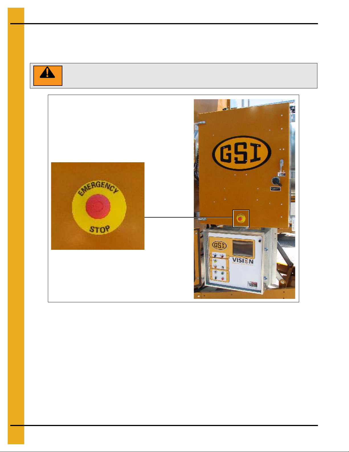
WARNING
Pushing the emergency stop switch does not interrupt the main power to the
upper control box panel.
Emergency Stop Switch
The emergency stop switch is located on the upper control box door. Pushing the emergency stop switch
will interrupt the control power and stop all dryer functions.
Figure 2A
Safety Instructions
Our foremost concern is your safety and the safety of others associated with this equipment. We want to
keep you as a customer. This manual is to help you understand safe operating procedures and some
problems that may be encountered by the operator and other personnel.
As owner and/or operator, it is your responsibility to know what requirements, hazards, and precautions
exist, and to inform all personnel associated with the equipment or in the area. Safety precautions may be
required from the personnel. Avoid any alterations to the equipment. Such alterations may p roduce a very
dangerous situation where SERIOUS INJURY or DEATH may occur.
This equipment shall be installed in accordance with the current installation codes and applicable
regulations, which should be carefully followed in all cases. Authorities having jurisdiction should be
consulted before installations are made.
6PNEG-338 Portable Dryer Installation and Towing
Page 7

2. Safety
CAUTION
Keep the dryer clean. Do not allow fine material to accumulate in the plenum
chamber or surrounding the outside of the dryer.
Safety Precautions
READ THESE INSTRUCTIONS BEFORE INSTALLATION AND OPERATION
SAVE FOR FUTURE REFERENCE
1. Read and understand the operating manual before trying to operate the dryer.
2. NEVER operate the dryer while the guards are removed.
3. Power supply should be OFF for service of electrical components. Use CAUTION in checking voltage
or other procedures that require the power to be ON.
4. Check for gas leaks at all gas pipe connections. If any leaks are detected, DO NOT operate dryer.
Shut down and repair before further operation.
5. NEVER attempt to operate the dryer by jumping or otherwise bypassing any safety devices on
the unit.
6. Set pressure regulator to avoid excessive gas pressure to burner during ignition and when burner is
in operation. DO NOT exceed maximum recommended drying temperature.
7. Keep the dryer clean. Clean grain is easier to dry. Fine material increases resistance to airflow
and requires removal of extra moisture. DO NOT allow fine material to accumulate in the
plenum chamber.
8. Keep auger drive belts tight enough to prevent slippage.
9. Use CAUTION in working around high speed fans, gas burners, augers and auxiliary conveyors
which can all START AUTOMATICALLY.
10. DO NOT operate in any area where combustible material will be drawn into the fan.
11. BEFORE attempting to remove and reinstall any propeller, read the procedure listed in the service
section of the manual.
12. Match the capacities of auxiliary conveyors to dryer auger capacities.
USE CAUTION IN THE OPERATION OF THIS EQUIPMENT
This dryer is designed and manufactured to maximize operator safety. However, grain dryers have
inherently hazardous components: a gas burner, high voltage electrical equipment, high speed rotating
parts, etc. It is not possible to fully safeguard again st all hazards withou t impeding efficient op eration and
reasonable access to components. Therefore, a careful and knowledgeable owner/operator is the best
insurance against an accident.
Use extreme caution when working around high speed fans, gas fired heaters, augers and auxiliary
conveyers, which may start without warning when the dryer is operating on automatic control.
Continued safe, dependable operation of automatic equipment depends, to a great degree, upon the
owner. For a safe and dependable drying system, follow the recomm endations within this manual and make
it a practice to regularly inspect the operation of the unit for any deve loping problems o r unsafe conditions.
Take special note of all safety precautions before attempting to operate the dryer.
PNEG-338 Portable Dryer Installation and Towing 7
Page 8

2. Safety
Safety Sign-Off Sheet
As a requirement of O.S.H.A., it is necessary for the employer to train the employee in the safe operating
and safety procedures for this equipment. This sign-off sheet is provided for your convenience and
personal record keeping. All unqualified persons are to stay out of the work area at all times. It is strongly
recommended that another qualified person who knows the shut down procedure be in the area in the
event of an emergency.
Date Employee Name Supervisor Name
8PNEG-338 Portable Dryer Installation and Towing
Page 9
3. Safety Alert Decals
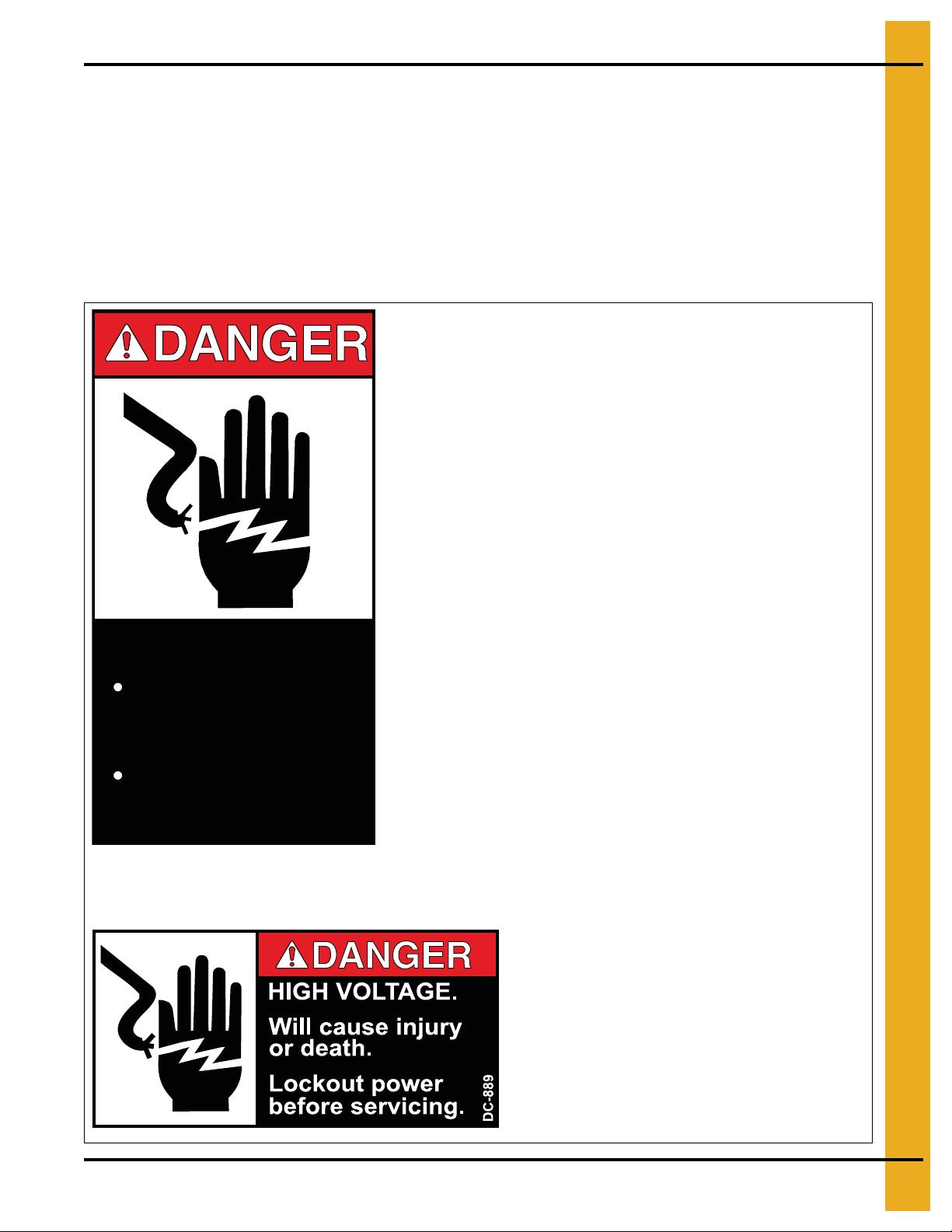
HIGH VOLTAGE.
Will cause serious
injury or death.
Lockout power
before servicing.
DC-1224
Decal: DC-889
Decal DC-889 has two (2) locations. One is located
inside the fan/heater control box and another one is
on the dryer upper control box door next to the main
power disconnect.
Decal: DC-1224
Decal DC-1224 is located in two (2) places on the fan/heater control box.
One is located on the lid and another one is on the front of the fan/heater
control box. An additional location for this decal is inside the upper control
box for the dryer.
The GSI Group recommends contacting your local power company and having a representative survey
your installation so the wiring is compatible with their system and adequate power is supplied to your unit.
Safety decals should be read and understood by all people in the grain handling area.
If a decal is damaged or is missing, contact:
Decals
1004 E. Illinois St.
Assumption, IL. 62510
Phone: 1-217-226-4421
A free replacement will be sent to you.
PNEG-338 Portable Dryer Installation and Towing 9
Page 10
3. Safety Alert Decals
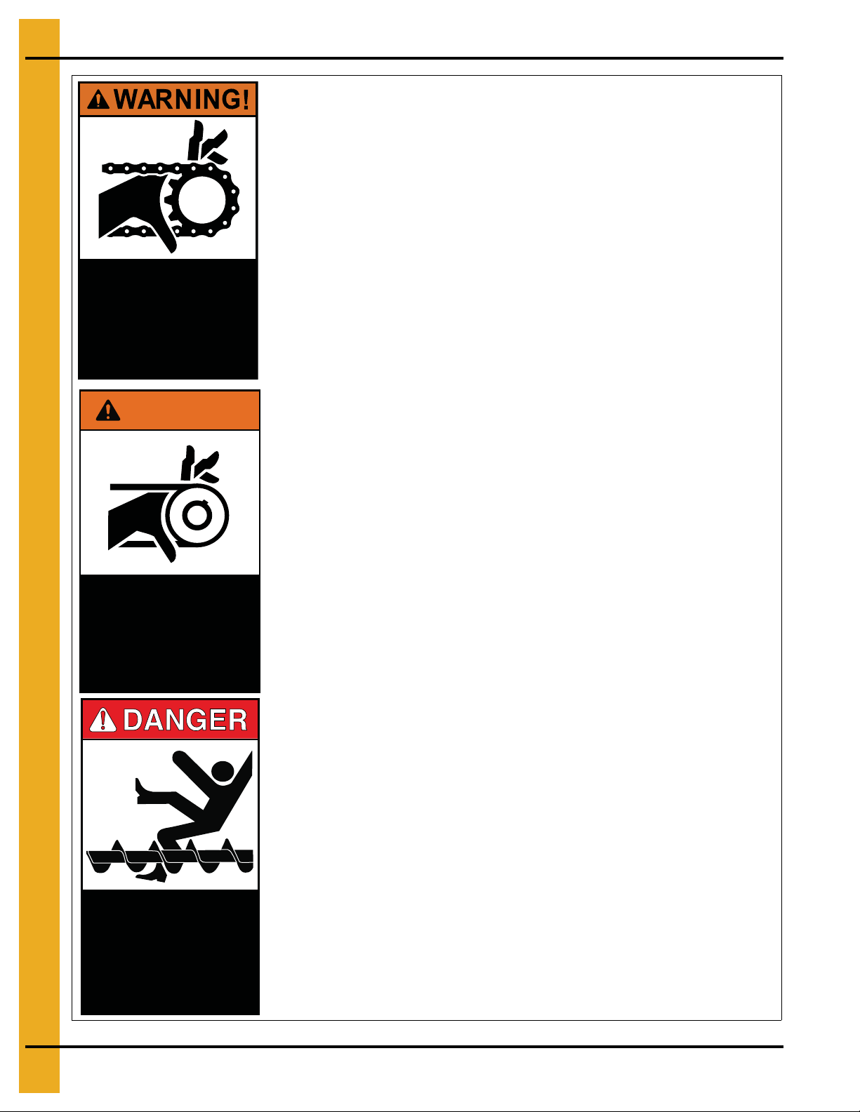
Moving parts can crush
and cut. Keep hands
clear. Do not operate
without guards in place.
Failure to do so could
result in serious injury.
DC-972
WARNING!
Automatically controlled
belt drive can start at
anytime. Keep hands
clear. Failure to do so
could result in serious
injury.
DC-971
Decal: DC-972
Decal DC-972 is located on the bottom auger belt guard and the front bearing plate (which
is visible when the bottom auger belt guard is removed). An alternate location would be at
the rear of the dryer for portable dryers equipped with the Front Discharge Option.
Decal: DC-971
Decal DC-971 is located on the bottom auger belt guard and the front bearing plate (which
is visible when the bottom auger belt guard is removed). An alternate location would be at
the rear of the dryer for portable dryers equipped with the
Front Discharge Option
.
An additional location for decal DC-971 is the top auger belt guard (one on the belt
guard cover and one inside on the belt guard body visible when the belt guard cover
is removed).
Decal: DC-974
Decal DC-974 has several different locations. Two (2) are located on the front end panel
below the fan/heater. Two (2) are located on the rear end panel below the rear access
door. T wo (2) are located on the auger discharge box (one on the outside top and one on
the inside of the flapper lid next to the discharge mercury switch). One more of these
decals is located inside the plenum on the rear plenum closure door just inside the rear
access door.
Rotating auger will crush
and cut. Auto equipment
can start at anytime. Do not
enter until electric power is
locked in off position. Failure
to do so will result in serious
10 PNEG-338 Portable Dryer Installation and Towing
injury or death.
DC-974
Page 11

3. Safety Alert Decals
DC-1227
Flame and pressure beyond
door can cause serious
injury. Do not operate with
service door removed. Keep
head and hands clear.
WARNING
Decal: DC-1227
Decal DC-1227 is located on the
fan/heater access door.
Decal: DC-1225
Decal DC-1225 is located on the
fan/heater access door.
Decal: DC-1229
Decal DC-1229 is located on each of
the meter roll access doors.
WARNING
Stay clear of rotating
blade. Blade could start
automatically. Can cause
serious injury. Disconnect
power before servicing.
WARNING
Rotating metering roll.
Equipment can start
automatically. Keep hands
PNEG-338 Portable Dryer Installation and Towing 11
clear. Can cause serious
injury. Disconnect power
before servicing.
DC-1225
DC-1229
Page 12

3. Safety Alert Decals
Automatic equipment can
start at any time. Do not
enter until fuel is shut off
and electrical power is
locked in off position.
Failure to do so will result
in serious injury or death.
DC-973
Decal: DC-973
Decal DC-973 is located on the rear plenum access door (inside
and outside).
Decal: DC-388
Decal DC-388 is located on the hitch tongue.
Decal: DC-1249
Decal DC-1249 is located on the hitch tongue.
3/4" MINIMUM
BOLT DIAMETER
Hitch pin must be
securely fastened and
no less than 3/4" in
diameter. Failure to
follow installation
16-17"
instructions may result
in property damage.
DC-388
HUB TEMPERATURE
NO GREATER THAN 150°F
150°
TIGHTEN TO
90FT-LBS.
Dryer must be
towed empty and
in accordance
050
CHECK AFTER 50 MILES AND EVERY 200 MILES
100
150
55-60 PSI
COLD
200 250
with state and
provincial
regulations.
DC-1249
12 PNEG-338 Portable Dryer Installation and Towing
Page 13

4. Transporting the Dryer
Washers
Locking nut
3/4" Minimum bolt diameter
The dryer is available with an optional transport kit for transporting the unit by truck or tractor. Make certain
to observe the following safety precautions.
1. Recommended towing hitch height is 14"-17''. (See Figure 4A.)
Figure 4A Use a 14"-17'' Towing Hitch Height and a Safety Chain
2. Hitch bolt must be at least 3/4" in diameter and securely fastened with a locking nut, so it will not
come out during travel and the hitch will not bend. (See Figure 4B.)
3. Be sure to minimize vertical hitch play with washers. (See Figure 4B.)
Figure 4B A 3/4'' hitch bolt and washers fastened with
a locking nut at the bottom of the hitch.
4. Always use a safety chain. (See Figure 4A.)
5. Dryer must by towed empty and in accordance with applicable state or provincial regulations.
NOTE: NEVER tow dryer with grain or any other material inside of it.
6. Recommended tire pressure is 55-60 PSI (cold).
7. Maximum towing speed is 45 miles per hour or the speed limit, whichever is lower.
8. After the first 50 miles and every 200 miles thereafter, check the following:
a. Dryer wheel hub and spindle temperature immediately after stopping. Temperature should not
exceed 150°F. It may be hot to touch, but not melting lubricant.
b. Wheel lug nuts. They are factory torqued at 115 to 120 Ft. Lbs. Retighten, if required.
PNEG-338 Portable Dryer Installation and Towing 13
Page 14

5. Installation
Location of the Dryer
When considering the exact location of the dryer, also consider the wet grain supply and dry grain
discharge, as well as the location of storage bins and other grain handling equipment. Do not install the
dryer inside a building or in any other area where not allowed by electrical codes, fuel installation
regulations and/or insurance requirements. Maintain a minimum distance of at least three feet from other
structures, otherwise air flow problems may occur. (See Page 15.) Do not operate in an area where
combustible materials can be drawn into the fans or where load and unload augers can come in contact
with power lines.
Foundation
A reinforced concrete pad or similar permanent foundation is recommended for dryer stability.
See Pages 16 and 17 for details.
Supporting the Dryer
The wheels are to be used for transporting the dryer only when empty. Before loading any grain into the
dryer, the frame of the unit on each side must be supported. Place concrete blocks on each side, every
six feet of the frame, as well as at the hitch mount location with the hitch removed. The blocks must be
able to support the dryer as well as the additional weight of the grain when full. Use shims to provide
uniform, level support for all blocks. The dryer sho uld be at least 16'' off th e pad to allow for clean-out and
the use of auxiliary grain handling equipment. The hitch tongue should be removed, but the hitch assembly
and the fan support must be left on during operation; they are not part of the transport tie down assembly.
NOTE: Use a minimum of one support per each six feet of basket length on each side.
Supporting the Dryer with the Optional Steel Support Legs
Anchor points may be cast into the concrete slab or the dryer may be tied down by cables and turnbuckles
to anchors installed at the edge of the slab. This helps prevent overturn or lateral
movement by wind or other forces.
Wet Grain Supply
A wet grain holding bin provides gravity flow to the dryer or loading conveyor. This conveyor may be
electrically connected to the power circuit provided in the main control box. Initially, the dryer will fill
completely. During drying, the top auger will start and stop as required depending upon the dry grain
discharge rate and grain shrinkage to maintain the dryer fill. If the dryer does not fill within the pre-set
time on the Out of Grain Timer (see owner’s manual for instructions on setting this timer), the dryer will
shut down.
Dry Grain Removal
The dry grain is normally discharged out of the rear end of the dryer. Front discharge is an optional feature.
A take away system needs to be provided to remove grain from the drying system. This conveyor may be
electrically connected to the power circuit provided in the main control box.
14 PNEG-338 Portable Dryer Installation and Towing
Page 15

Figure 5A Diagram of Dryer Dimensions
5. Installation
Transport and Installation Dimensions
Driver
Model #
1108 11' 6'' 8' 13' 11' 8'' 10' 1'' 6' 5'' 8' 14' 9'' 16' 10''
1110 11' 6'' 8' 13' 11' 8'' 10' 1'' 6' 5'' 8' 16' 9'' 18' 10''
1112 13' 5'' 8' 14' 6'' 13' 2'' 11' 7'' 6' 5'' 8' 18 ' 9'' 20' 10''
1114 1214 13' 5'' 8' 14' 6'' 13' 2'' 11' 7'' 6' 5'' 8' 20' 9'' 22' 10''
1116 1216 13' 5'' 8' 14' 6'' 13' 2'' 11' 7'' 6' 5'' 8' 22' 9'' 24' 10''
1118 1218 13' 5'' 8' 14' 6'' 13' 2'' 11' 7'' 6' 5'' 8' 24' 9'' 26' 10''
1120 1220 13' 5'' 8' 14' 6'' 13' 2'' 11' 7'' 6' 5'' 8' 26' 9'' 28' 10''
1122 1222 13' 5'' 8' 14' 6'' 13' 2'' 11' 7'' 6' 5'' 8' 28' 9'' 30' 10''
1126 1226 13' 5'' 8' 14' 6'' 13' 2'' 11' 7'' 6' 5'' 8' 32' 9'' 34' 10''
1314 13' 5'' 8' 14' 6'' 13' 2'' 11' 7'' 6' 5'' 8' 20' 9'' 22' 10''
1318 13' 5'' 8' 14' 6'' 13' 2'' 11' 7'' 6' 5'' 8' 24' 9'' 26' 10''
1322 13' 5'' 8' 14' 6'' 13' 2'' 11' 7'' 6' 5'' 8' 28' 9'' 30' 10''
1214S 13' 5'' 11' 2'' 14' 6'' 13' 2'' 11' 7'' 6' 5'' 8' 20' 9'' 22' 9''
1218S 13' 5'' 11' 2'' 14' 6'' 13' 2'' 11' 7'' 6' 5'' 8' 24' 9'' 26' 10''
1220S 13' 5'' 11' 2'' 14' 6'' 13' 2'' 11' 7'' 6' 5'' 8' 26' 9'' 28' 10''
1222S 13' 5'' 11' 2'' 14' 6'' 13' 2'' 11' 7'' 6' 5'' 8' 28' 9'' 30' 10''
1226S 13' 5'' 11' 2'' 14' 6" 13' 2'' 11 ' 7'' 6' 5'' 8' 32' 9'' 34' 10''
160AB 11' 11'' 8' N/A 11' 8'' 10' 1'' 6' 5'' 8' 12' 9'' 14' 10''
210AB 11' 11'' 8' N/A 11' 8'' 10' 1'' 6' 5'' 8' 14' 9'' 16' 10''
300AB 13' 5'' 8' N/A 13' 3'' 11' 7'' 6' 5'' 8' 16' 9'' 18' 10''
375AB 13' 5'' 8' N/A 13' 3'' 11' 7'' 6' 5'' 8' 18' 9'' 20' 10''
400AB 13' 5'' 8' N/A 13' 3'' 11' 7'' 6' 5'' 8' 20' 9'' 22' 10''
415AB 13' 5'' 8' N/A 13' 3'' 11' 7'' 6' 5'' 8' 20' 9'' 22' 10''
600AB 13' 5'' 8' N/A 13' 3'' 11' 7'' 6' 5'' 8' 26' 9'' 28' 10''
ABCDEFGH
Transport
Height
Installed
Width
Installed
Wet Bin
Height
Standard
Height w/o
Wet Bin
Frame
Width
Transport
Width
Installed
Length
Transport
Length
PNEG-338 Portable Dryer Installation and Towing 15
Page 16

6. Foundation Layout Typical of Dryer Line
Figure 6A
16 PNEG-338 Portable Dryer Installation and Towing
Page 17

7. Foundation Specifications for Dryer
Minimum Bag Mix for Concrete Strength per Model Weight
Dryer Basket Length 6 8 10 12 14 16 18 20 22 26
Concrete Pad Size 12 x 16 12 x 18 12 x 20 12 x 22 12 x 24 12 x 26 12 x 28 12 x 30 12 x 32 12 x 36
Yards Concrete 5.3 5.9 6.5 7.1 7.7 8.3 8.9 9.2 10.1 11.3
Reinforcing Rods 20" each
Wire Mesh Sq. Ft. 192 216 240 264 288 312 336 360 384 432
Steel Legs (Minimum) 8 8 10 10 12 12 14 14 16 18
Anchors 4 4 4 6 6 6 8 8 8 10
Blocks 10 14 14 18 18 18 22 22 26 30
Foot of 2 x 6 10 14 14 18 18 18 22 22 26 30
Turnbuckles 44466688810
Estimated Manhours 8 10 12 14 18 18 20 22 24 28
Quantities are approximate and requirements may vary due to site elevations.
Setup times do not include site preparation and pouring concrete pad.
6 6 7 7 7 8 8 8 9 10
PNEG-338 Portable Dryer Installation and Towing 17
Page 18

8. Fuel Connection
See Fuel Specification Chart
on Page 19 for recommended
line use.
Liquid Propane (LP)
Liquid Draw
The dryers have internal vaporizers and are designed to operate on liquid draw from the supply tank. The
tank should be 1000 gallons or larger and should not have a regulator mounted to it. The connection to
the dryer should be with a flexible hose designed for LP gas, See Chart on Page 19 for proper size.
Consult your LP gas dealer for proper fittings, connection hose and safety controls required to meet local
standards and to conform with National Fire Protection Association standards. The piping train on the
dryer includes strainer, pressure relief valve, electronic safety shut off valve (on some models) and a
pressure regulator between the vaporizer and burner.
Ammonia Tanks
Do not use tanks which have previously been used for ammonia or fertilizer solutions. These substances
are extremely corrosive and will damage fuel supply and burner parts.
Oil or Water in Tanks
With liquid draw from the supply tank, any water or oil present in the tank may freeze in the pipe train or
controls causing damage. To make sure the tank is free of moisture, it can be purged with methanol. Avoid
tanks which may contain an accumulation of oil or heavy hydrocarbon from long use on a vapor withdrawal
system.
Figure 8A Grain dryer connected to a liquid propane tank.
18 PNEG-338 Portable Dryer Installation and Towing
Page 19

8. Fuel Connection
See Fuel Specifications Chart on
Page 20 for required pressure and
typical maximum fuel flow rates.
See Fuel Specifications Chart
on Page 20 for recommended
line size.
Fuel System Specifications and Recommendations (LP) Liquid Propane
Dryer
Model #
1108 3,000,000 33 1/2'' 1/4''
1110 3,500,000 38 1/2'' 9/32''
1112 4,500,000 49 1/2'' 21/64''
1114 5,750,000 63 1/2'' 11/32''
1116 5,750,000 63 1/2'' 11/32''
1118 6,750,000 74 1/2'' 3/8''
1120 7,500,000 82 1/2'' 25/64''
1122 8,750,000 96 3/4'' 7/16''
1126 10,250,000 112 3/4'' 29/64''
1214 6,200,000 68 3/4'' (U)9/32'' (L)7/32''
1216 7,200,000 79 3/4'' (U)21/64'' (L)7/32''
1218 7,200,000 79 3/4'' (U)21/64'' (L)7/32''
1220 8,500,000 93 3/4'' (U)11/32'' (L)1/4''
1222 9,750,000 107 3/4'' (1)3/8'' (1)1/4''
1226 10,500,000 115 3/4'' (1)25/64'' (1)1/4''
1314 8,100,000 88 3/4'' (3)7/32''
1318 8,100,000 88 3/4'' (3)7/32''
1322 8,100,000 88 3/4'' (3)7/32''
160AB 3,000,000 33 1/2'' 1/4''
210AB 3,500,000 33 1/2'' 1/4''
300AB 4,500,000 49 1/2'' 21/64''
375AB 5,500,000 60 1/2'' 21/64''
400AB 5,500,000 60 1/2'' 21/64''
415AB 7,000,000 66 1/2'' (2)9/32''
600AB 9,000,000 98 3/4'' (2)21/64''
* The minimum size of the fuel line for distances of 30.48 m (100 ft.).
Maximum Heat
Capacity BTU Per Hour
Maximum Fuel Flow
Gals Per Hour
Fuel Line Size* Heater Orifice Drill Size
Natural Gas (N)
Gas Volume and Pressure
The dryer is designed to operate on natural gas having a heat value of approximately 1000 BTU per cubic
foot. The dryer is equipped with a natural gas supply pipe system connected to the heater solenoid valves.
A regulated pressure of 10 PSI must be provided at the connection to the dryer, with gas available in
sufficient volume to maintain the operating pressure.
Figure 8B Grain dryer connected to a natural gas supply tank.
PNEG-338 Portable Dryer Installation and Towing 19
Page 20

8. Fuel Connection
Fuel System Specifications and Recommendations (N) Natural Gas
Dryer
Model #
1108 3,000,000 3,000 1-1/4'' 3/8''
1110 3,500,000 3,500 1-1/4'' 13/32''
1112 4,500,000 4,500 1-1/2'' 1/2''
1114 5,750,000 5,750 1-1/2'' 33/64''
1116 5,750,000 5,750 1-1/2'' 33/64''
1118 6,750,000 6,750 2'' 35/64''
1120 7,500,000 7,500 2'' 37/64''
1122 8,750,000 8,750 2'' 19/32''
1126 10,250,000 10,250 2'' 41/64''
1214 6,200,000 6,200 1-1/2'' (1)13/32'' (1)5/16''
1216 7,200,000 7,200 2'' (1)1/2'' (1)5/16''
1218 7,200,000 7,200 2'' (1)1/2'' (1)5/16''
1220 8,500,000 8,500 2'' (1)33/64'' (1)3/8''
1222 9,750,000 9,750 2'' (1)35/64'' (1)3/8''
1226 10,500,000 10,500 2'' (1)37/64'' (1)3/8''
1214S 6,000,000 6,000 1-1/2'' (2)3/8''
1218S 6,000,000 6.000 1-1/2'' (2)13/32''
1220S 9,000,000 9,000 2'' (2)1/2''
1222S 9,000,000 9,000 2'' (2)1/2''
1226S 13,500,000 13,500 2'' (2)17/32''
1314 8,100,000 8,100 2'' (3)5/16''
1318 8,100,000 8,100 2'' (3)5/16''
1322 8,100,000 8,100 2'' (3)5/16''
160AB 3,000,000 3,000 1-1/4'' 3/8''
210AB 3,500,000 3,500 1-1/4'' 13/32''
300AB 4.500,000 4,500 1-1/2'' 1/2''
375AB 5,500,000 5,500 1-1/2'' 33/64''
400AB 5,500,000 5,500 1-1/2'' 33/64''
415AB 7,000,000 7,000 2'' (2)13/32''
600AB 9,000,000 9,000 2'' (2)1/2''
* The minimum size of the fuel line for distances of 30.48 m (100 ft.).
Maximum Heat
Capacity BTU Per Hour
Maximum Fuel Flow
Cubic Feet Per Hour
Fuel Line Size* (Dia.) Heater Orifice Drill Size
Figure 8C The fuel connection point is equipped with a
Y-strainer and Maxon safety valve.
20 PNEG-338 Portable Dryer Installation and Towing
Page 21

9. Electrical Power Supply
Power Supply
An adequate power supply and proper wiring are important factors for maximum performance and long
life of the dryer. Electrical service must be adequate to prevent low voltage damage to motors and co ntrol
circuits. (See Electrical Load Information on Pages 23-30.) Power supply for single phase models must
include a neutral wire.
Transformers and Wiring Voltage Drop
Advise the service representative of the local power supplier that an additional load will be placed on the
line. Check the KVA rating of transformers, considering total horsepower load. The power supply wiring,
main switch equipment and transformers must provide adequate motor starting and operating voltage.
Voltage drop during motor starting should not exceed 14% of normal voltage. After motor is running at full
speed, it should be within 8% of normal voltage. Check electrical load information
HP ratings and maximum amp loads.
(See Pages 23-30)
for
Power Supply Disconnect
All dryers are equipped with a power disconnect switch in the power box to permit total power shut down
before opening the power box door, as required for inspection and service. The power disconnect switch
is located on the power box door for quick shut down.
Machine to Earth Grounding
A Machine to Earth Ground Rod must be installed at the dryer. Place the ground rod that comes standard
within eight feet of the dryer and attach it to the dryer control panel with at least a #6 solid, bare, copper
ground wire and the clamp provided. The grounding rod located at the power pole will not provide
adequate grounding for the dryer. Proper grounding will provide additional safety in case of any short and
will ensure long life of all circuit boards, the SCR drive and the ignition system. The ground rod must be in
accordance with local requirements.
Figure 9A Installation of a ground rod (standard with dryer purch ase) specifically
for the grain dryer is necessary for safety and equipment preservation.
PNEG-338 Portable Dryer Installation and Towing 21
Page 22

9. Electrical Power Supply
Proper Installation of Ground Rod
The rod should not be driven into dry ground. Follow these instructions for proper installation.
1. Dig a hole large enough to hold one to two (2) gallons of water.
2. Fill hole with water.
3. Insert rod through water and “jab” it into the ground.
4. Continue “jabbing” the rod up and down. This allows the water to work its way into the ground,
allowing it to be completely inserted into the ground. This method of installation also assures good
contact with the surrounding soil, thereby making a proper ground.
5. Connect the bare, copper ground wire to the rod with the proper clamp.
6. Connect ground wire to control panel with the ground lug provided in the control box.
7. Ground wire must not have any breaks or splices. Do not use insulated wire for
grounding applications.
Connecting Auxiliary Conveyors
The auxiliary load and auxiliary unload augers or conveyors can be wired directly to the dryer. Electrical
Load Information on Pages 23-30 shows the maximum horse power and amps of auxiliaries that can be
wired to the dryer. If an auxiliary motor is larger than recommended, it must be powered from a source
outside the dryer and must use a separate contactor and overload protection device for each motor.
However, the operation of the auxiliaries can be performed by the control panel.
22 PNEG-338 Portable Dryer Installation and Towing
Page 23

10. Electrical Load Information
The following charts provide information for the electrician wiring the grain dryer and are a reference
guide for parts. You should contact the local power company and have a representative survey the
installation to see that the wiring is compatible with their system and that adequate power is supplied to
the unit. Remember that the only thing connected to the recommended service amps should be the
grain dryer.
Adhere to all electrical safety practices and codes. (Refer to the National Electrical Code Standard
handbook by the National Fire Protection Association.) A qualified electrician must make all electrical
wiring installations.
Dryer
Model #
1108
1110
1112
*Auxiliaries run through load and unload breakers.
Subject to change without notification.
Voltage Motor HP
Top Auger 1.5 8
1 PH 230V
3 PH 220V
3 PH 440V
1 PH 230V
3 PH 220V
3 PH 440V
1 PH 230V
3 PH 220V
3 PH 440V
Bottom Auger 1 6.5 60
Fan 10 to 12 48 100
(2) Auxiliary (2) 7.5 62 *
Top Auger 1.5 5
Bottom Auger 1 3.4 50
Fan 10 to 12 33 60
(2) Auxiliary (2) 7.5 40 *
Top Auger 1.5 2.5
Bottom Auger 1 1.7 60
Fan 10 to 12 16.5 60
(2) Auxiliary (2) 7.5 20 *
Top Auger 2 14
Bottom Auger 1.5 8 60
Fan 10 to 12 48 100
(2) Auxiliary (2) 7.5 62 *
Top Auger 2 6.2
Bottom Auger 1.5 5 50
Fan 10 28 60
(2) Auxiliary (2) 7.5 40 *
Top Auger 2 3.1
Bottom Auger 1.5 2.5 60
Fan 10 14 60
(2) Auxiliary (2) 7.5 20 *
Top Auger 2 14
Bottom Auger 1.5 8 60
Fan 10 to 17 78 100
(2) Auxiliary (2) 7.5 62 *
Top Auger 2 6.2
Bottom Auger 1.5 5 50
Fan 15 39 60
(2) Auxiliary (2) 7.5 40 *
Top Auger 2 3.1
Bottom Auger 1.5 2.5 60
Fan 15 19.5 60
(2) Auxiliary (2) 7.5 20 *
Fuel Load
Amps
Maximum Amps
with Auxiliaries
153 62.5 200
104 41.4 150
57 20.7 150
162 70 225
101 39.2 150
56 19.6 150
196 100 300
114 50.2 175
62 25.1 150
Minimum
Amps
Recommended
Service in Amps
Branch Breaker
in Amps
60
50
60
60
50
60
60
50
60
PNEG-338 Portable Dryer Installation and Towing 23
Page 24

10. Electrical Load Information
Dryer
Model #
1114
1116
1118
1120
1122
*Auxiliaries run through l oad and unload breakers.
Voltage Motor HP
Top Auger 5 26
1 PH 230V
3 PH 220V
3 PH 440V
1 PH 230V
3 PH 220V
3 PH 440V
3 PH 220V
3 PH 440V
3 PH 220V
3 PH 440V
3 PH 220V
3 PH 440V
Bottom Auger 5 26 100
Fan 10 to 17 78 100
(2) Auxiliary (2) 7.5 62 *
Top Auger 5 13.2
Bottom Auger 5 13.2 60
Fan 15 39 60
(2) Auxiliary (2) 10 52 *
Top Auger 5 6.6
Bottom Auger 5 6.6 60
Fan 15 19.5 60
(2) Auxiliary (2) 10 26 *
Top Auger 5 26
Bottom Auger 5 26 100
Fan 10 to 17 78 100
(2) Auxiliary (2) 7.5 62 *
Top Auger 5 13.2
Bottom Auger 5 13.2 60
Fan 15 39 60
(2) Auxiliary (2) 10 52 *
Top Auger 5 6.6
Bottom Auger 5 6.6 60
Fan 15 19.5 60
(2) Auxiliary (2) 10 26 *
Top Auger 5 13.2
Bottom Auger 5 13.2 60
Fan 20 50 90
(2) Auxiliary (2) 10 52 *
Top Auger 5 6.6
Bottom Auger 5 6.6 60
Fan 20 25 60
(2) Auxiliary (2) 10 26 *
Top Auger 7.5 20
Bottom Auger 7.5 20 90
Fan 25 64 90
(2) Auxiliary (2) 15 78 *
Top Auger 7.5 10
Bottom Auger 7.5 10 60
Fan 25 32 60
(2) Auxiliary (2) 15 39 *
Top Auger 7.5 20
Bottom Auger 7.5 20 90
Fan 30 74 90
(2) Auxiliary (2) 15 78 *
Top Auger 7.5 10
Bottom Auger 7.5 10 60
Fan 30 37 60
(2) Auxiliary (2) 15 39 *
Fuel Load
Amps
Maximum Amps
with Auxiliaries
231 130 350
145 65.4 200
78 32.7 150
231 130 350
145 65.4 200
78 32.7 150
158 76.4 250
84 38.2 150
219 104 300
115 52 200
231 114 300
120 57 200
Minimum
Amps
Recommended
Service in Amps
Branch Breaker
in Amps
100
60
60
100
60
60
60
60
90
60
90
60
24 PNEG-338 Portable Dryer Installation and Towing
Page 25

10. Electrical Load Information
Dryer
Model #
1126
1214
1216
*Auxiliaries run through load and unload breakers.
Voltage Motor HP
Top Auger 10 26
3 PH 220V
3 PH 440V
1 PH 230V
3 PH 220V
3 PH 440V
1 PH 230V
3 PH 220V
3 PH 440V
Bottom Auger 10 26 90
Fan 40 102 125
(2) Auxiliary (2) 15 78 *
Top Auger 10 13
Bottom Auger 10 13 60
Fan 40 51 90
(2) Auxiliary (2) 15 39l *
Top Auger 5 26
Bottom Auger 5 26 100
Top Fan 10 to 12 48 100
Bottom Fan 10 to 12 48 100
(2) Auxiliary (2) 7.5 62 *
Top Auger 5 13.2
Bottom Auger 5 13.2 60
Top Fan 10 28 60
Bottom Fan 10 to 12 33 60
(2) Auxiliary (2) 10 52 *
Top Auger 5 6.6
Bottom Auger 5 6.6 60
Top Fan 10 14 60
Bottom Fan 10 to 12 16.5 60
(2) Auxiliary (2) 10 26 *
Top Auger 5 26
Bottom Auger 5 26 100
Top Fan 10 to 17 78 100
Bottom Fan 10 to 12 48 100
(2) Auxiliary (2) 7.5 62 *
Top Auger 5 13.2
Bottom Auger 5 13.2 60
Top Fan 15 39 60
Bottom Fan 10 to 12 33 60
(2) Auxiliary (2) 10 52 *
Top Auger 5 6.6 60
Bottom Auger 5 6.6
Top Fan 15 19.5 60
Bottom Fan 10 to 12 16.5 60
(2) Auxiliary (2) 10 26 *
Fuel Load
Amps
Maximum Amps
with Auxiliaries
277 154 400
143 77 250
252 148 300
170 87.4 225
90 43.7 150
286 178 400
183 98.4 225
96 49.2 150
Minimum
Amps
Recommended
Service in Amps
Branch Breaker
in Amps
90
60
100
60
60
100
60
60
PNEG-338 Portable Dryer Installation and Towing 25
Page 26

10. Electrical Load Information
Dryer
Model #
1218
1220
1222
1226
*Auxiliaries run through l oad and unload breakers.
Voltage Motor HP
Top Auger 5 26
Bottom Auger 5 26 100
1 PH 230V
3 PH 220V
3 PH 440V
1 PH 230V
3 PH 220V
3 PH 440V
3 PH 220V
3 PH 440V
3 PH 220V
3 PH 440V
Top Fan 10 to 17 78 100
Bottom Fan 10 to 12 48 100
(2) Auxiliary (2) 7.5 62 *
Top Auger 5 13.2
Bottom Auger 5 13.2 60
Top Fan 15 39 60
Bottom Fan 10 to 12 33 60
(2) Auxiliary (2) 10 52 *
Top Auger 5 6.6
Bottom Auger 5 6.6 60
Top Fan 15 19.5 60
Bottom Fan 10 to 12 16.5 60
(2) Auxiliary (2) 10 26 *
Top Auger 7.5 31
Bottom Auger 7.5 31 100
Top Fan 10 to 17 78 100
Bottom Fan 10 to 12 48 100
(2) Auxiliary (2) 7.5 62 *
Top Auger 7.5 20
Bottom Auger 7.5 20 90
Top Fan 15 39 60
Bottom Fan 10 to12 33 60
(2) Auxiliary (2) 15 78 *
Top Auger 7.5 10
Bottom Auger 7.5 10 60
Top Fan 15 19.5 60
Bottom Fan 10 to 12 16.5 60
(2) Auxiliary (2) 15 39 *
Top Auger 7.5 20
Bottom Auger 7.5 20 90
Top Fan 20 50 90
Bottom Fan 10 to 12 33 60
(2) Auxiliary (2) 15 78 *
Top Auger 7.5 10
Bottom Auger 7.5 10 60
Top Fan 20 25 60
Bottom Fan 10 to 12 16.5 60
(2) Auxiliary (2) 15 39 *
Top Auger 10 26
Bottom Auger 10 26 90
Top Fan 25 64 90
Bottom Fan 10 to 12 33 60
(2) Auxiliary (2) 15 78 *
Top Auger 10 13
Bottom Auger 10 13 60
Top Fan 25 32 60
Bottom Fan 10 to 12 16.5 60
(2) Auxiliary (2) 15 39 *
Fuel Load
Amps
Maximum Amps
with Auxiliaries
286 178 400
183 98.4 225
96 49.2 150
298 188 400
229 112 300
123 59 200
241 123 350
129 64.5 200
271 149 350
144 77.5 200
Minimum
Amps
Recommended
Service in Amps
Branch Breaker
in Amps
100
60
60
100
90
60
90
60
90
60
26 PNEG-338 Portable Dryer Installation and Towing
Page 27

10. Electrical Load Information
Dryer
Model #
1214S
1218S
1220S
1222S
*Auxiliaries run through load and unload breakers.
Voltage Motor HP
Top Auger 5 26
1 PH 230V
3 PH 220V
3 PH 440V
1 PH 230V
3 PH 220V
3 PH 440V
1 PH 230V
3 PH 220V
3 PH 440V
1 PH 230V
3 PH 220V
3 PH 440V
Bottom Auger 5 26 C303B 100
(2) Fans (2) 10 to 12 96 F614B 100
(2) Auxiliary (2) 7.5 62 C330B *
Top Auger 5 13.2
Bottom Auger 5 13.2 C163B 60
(2) Fans (2) 10 to 12 66 C366B 60
(2) Auxiliary (2) 10 52 C303B *
Top Auger 5 6.6
Bottom Auger 5 6.6 C867A 60
(2) Fans (2) 10 to 12 33 C180B 60
(2) Auxiliary (2) 10 26 C163B *
Top Auger 5 26
Bottom Auger 5 26 100
(2) Fans (2) 10 to 12 96 100
(2) Auxiliary (2) 7.5 62 *
Top Auger 5 13.2
Bottom Auger 5 13.2 60
(2) Fans (2 ) 10 56 60
(2) Auxiliary (2) 10 52 *
Top Auger 5 6.6
Bottom Auger 5 6.6 60
(2) Fans (2) 10 28 60
(2) Auxiliary (2) 10 26 *
Top Auger 7.5 31
Bottom Auger 7.5 31 100
(2) Fans (2) 10 to 17 156 100
(2) Auxiliary (2) 7.5 62 *
Top Auger 7.5 20
Bottom Auger 7.5 20 90
(2) Fans (2) 15 78 60
(2) Auxiliary (2) 15 78 *
Top Auger 7.5 10
Bottom Auger 7.5 10 60
(2) Fans (2) 15 39 60
(2) Auxiliary (2) 15 39 *
Top Auger 7.5 31
Bottom Auger 7.5 31 100
(2) Fans (2) 10 to 17 156 100
(2) Auxiliary (2) 7.5 62 *
Top Auger 7.5 20
Bottom Auger 7.5 20 90
(2) Fans (2) 15 78 60
(2) Auxiliary (2) 15 78 *
Top Auger 7.5 10
Bottom Auger 7.5 10 60
(2) Fans (2) 15 39 60
(2) Auxiliary (2) 15 39 *
Fuel Load
Amps
Maximum Amps
with Auxiliaries
252 148 350
176 92.4 225
93 46.2 150
252 148 350
165 82.4 225
87 41.2 150
332 218 400
235 118 300
123 59 200
332 218 400
235 118 300
123 59 200
Minimum
Amps
Recommended
Service in Amps
Branch Breaker
in Amps
C303B 100
C163B 60
C867A 60
100
60
60
100
90
60
100
90
60
PNEG-338 Portable Dryer Installation and Towing 27
Page 28

10. Electrical Load Information
Dryer
Model #
1226S
1314
1318
1322
*Auxiliaries run through l oad and unload breakers.
Voltage Motor HP
Top Auger 10 26
3 PH 220V
3 PH 440V
1 PH 230V
3 PH 220V
3 PH 440V
1 PH 230V
3 PH 220V
3 PH 440V
Bottom Auger 10 26 90
(2) Fans (2) 25 128 90
(2) Auxiliary (2) 15 78 *
Top Auger 10 13
Bottom Auger 10 13 60
(2) Fans (2) 25 64 60
(2) Auxiliary (2) 15 39 *
Top Auger 5 26
Bottom Auger 5 26 100
Top Fan 10 to 12 48 100
Mid.Fan 10 to 12 48 100
Bottom Fan 10 to 12 48 100
(2) Auxiliary (2) 7.5 62 *
Top Auger 5 13.2
Bottom Auger 5 13.2 60
Top Fan 10 to 12 33 60
Mid.Fan 10 to 12 33 60
Bottom Fan 10 to 12 33 60
(2) Auxiliary (2) 10 52 *
Top Auger 5 6.6
Bottom Auger 5 6.6 60
Top Fan 10 to 12 16.5 60
Mid.Fan 10 to 12 16.5 60
Bottom Fan 10 to 12 16.5 60
(2) Auxiliary (2) 10 26 *
Top Auger 7.5 31
Bottom Auger 7.5 31 100
Top Fan 10 to 12 48 100
Mid.Fan 10 to 12 48 100
Bottom Fan 10 to 12 48 100
(2) Auxiliary (2) 7.5 62 *
Top Auger 7.5 20
Bottom Auger 7.5 20 90
Top Fan 10 to 12 33 60
Mid.Fan 10 to 12 33 60
Bottom Fan 10 to 12 33 60
(2) Auxiliary (2) 15 78 *
Top Auger 7.5 10
Bottom Auger 7.5 10 60
Top Fan 10 to 12 16.5 60
Mid.Fan 10 to 12 16.5 60
Bottom Fan 10 to 12 16.5 60
(2) Auxiliary (2) 15 39 *
Fuel Load
Amps
Maximum Amps
with Auxiliaries
307 180 400
158 90 200
307 196 400
214 125.4 250
112 62.7 200
318 206 400
260 139 350
135 69.5 200
Minimum
Amps
Recommended
Service in Amps
Branch Breaker
in Amps
90
60
100
60
60
100
90
60
28 PNEG-338 Portable Dryer Installation and Towing
Page 29

10. Electrical Load Information
Dryer
Model #
160AB
210AB
300AB
375AB
*Auxiliaries run through load and unload breakers.
Voltage Motor HP
Top Auger 1 6.5
Bottom Auger 1 6.5 50
1 PH 230V
3 PH 220V
3 PH 440V
1 PH 230V
3 PH 220V
3 PH 440V
1 PH 230V
3 PH 220V
3 PH 440V
1 PH 230V
3 PH 220V
3 PH 440V
Fan 10 to 12 48 60
(2) Auxiliary (2) 7.5 62 *
Top Auger 1 3.4
Bottom Auger 1 3.4 60
Fan 10 to 12 33 60
(2) Auxiliary (2) 7.5 40 *
Top Auger 1 1.7
Bottom Auger 1 1.7 60
Fan 10 to 12 16.5 60
(2) Auxiliary (2) 7.5 20 *
Top Auger 2 14
Bottom Auger 2 14 60
Fan 10 to 12 48 100
(2) Auxiliary (2) 7.5 62 *
Top Auger 2 6.2
Bottom Auger 2 6.2 50
Fan 10 28 60
(2) Auxiliary (2) 7.5 40 *
Top Auger 2 3.1
Bottom Auger 2 3.1 60
Fan 10 14 60
(2) Auxiliary (2) 7.5 20 *
Top Auger 3 17.7
Bottom Auger 3 17.7 60
Fan 10 to 17 78 100
(2) Auxiliary (2) 7.5 62 *
Top Auger 3 8.6
Bottom Auger 3 8.6 60
Fan 15 39 60
(2) Auxiliary (2) 7.5 40 *
Top Auger 3 4.3
Bottom Auger 3 4.3 60
Fan 15 19.5 60
(2) Auxiliary (2) 7.5 20 *
Top Auger 3 17.7
Bottom Auger 3 17.7 60
Fan 10 to 17 78 100
(2) Auxiliary (2) 7.5 62 *
Top Auger 3 8.6
Bottom Auger 3 8.6 60
Fan 15 39 60
(2) Auxiliary (2) 7.5 40 *
Top Auger 3 4.3
Bottom Auger 3 4.3 60
Fan 15 19.5 60
(2) Auxiliary (2) 7.5 20 *
Fuel Load
Amps
Maximum Amps
with Auxiliaries
151 61 200
102 39.8 150
56 19.9 150
169 76 225
102 40.4 150
56 20.2 150
212 113.4 300
121 56.2 175
65 28.1 150
212 113.4 300
121 56.2 175
65 28.1 150
Minimum
Amps
Recommended
Service in Amps
Branch Breaker
in Amps
50
60
60
60
50
60
60
60
60
60
60
60
PNEG-338 Portable Dryer Installation and Towing 29
Page 30

10. Electrical Load Information
Dryer
Model #
400AB
415AB
600AB
*Auxiliaries run through l oad and unload breakers.
Voltage Motor HP
Top Auger 5 26
1 PH 230V
3 PH 220V
3 PH 440V
1 PH 230V
3 PH 220V
3 PH 440V
1 PH 230V
3 PH 220V
3 PH 440V
Bottom Auger 5 26 100
Fan 10 to 17 78 100
(2) Auxiliary (2) 7.5 62 *
Top Auger 5 13.2
Bottom Auger 5 13.2 60
Fan 15 39 60
(2) Auxiliary (2) 10 52 *
Top Auger 5 6.6
Bottom Auger 5 6.6 60
Fan 15 19.5 60
(2) Auxiliary (2) 10 26 *
Top Auger 5 26
Bottom Auger 5 26 100
Fan (2) 10 to 12 96 100
(2) Auxiliary (2) 7.5 62 *
Top Auger 5 13.2
Bottom Auger 5 13.2 60
Fan (2) 10 56 60
(2) Auxiliary (2) 10 52 *
Top Auger 5 6.6
Bottom Auger 5 6.6 60
Fan (2) 10 28 60
(2) Auxiliary (2) 10 26 *
Top Auger 7.5 31
Bottom Auger 7.5 31 100
Fan (2) 10 to 17 156 100
(2) Auxiliary (2) 7.5 62 *
Top Auger 7.5 20
Bottom Auger 7.5 20 90
Fan (2) 15 78 60
(2) Auxiliary (2)15 78 *
Top Auger 7.5 10
Bottom Auger 7.5 10 60
Fan (2) 15 39 60
(2) Auxiliary (2) 15 39 *
Fuel Load
Amps
Maximum Amps
with Auxiliaries
231 130 350
145 65.4 200
78 32.7 150
252 148 350
165 82.4 225
82 41.2 150
332 218 400
235 118 300
123 59 200
Minimum
Amps
Recommended
Service in Amps
Branch Breaker
in Amps
100
60
60
100
60
60
100
90
60
30 PNEG-338 Portable Dryer Installation and Towing
Page 31

11. Warranty
9101239_1_CR_rev7.DOC (revised July 2009)
GSI Group, LLC Limited Warranty
The GSI Group, LLC (“GSI”) warrants products which it manufactures to be free of defects in materials and workmanship
under normal usage and conditions for a period of 12 months after sale to the original end-user or if a foreign sale,
14 months from arrival at port of discharge, whichever is earlier. The end-user’s sole remedy (and GSI’s only obligation)
is to repair or replace, at GSI’s option and expense, products that in GSI’s judgment, contain a material defect in materials
or workmanship. Expenses incurred by or on behalf of the end-user without prior written authorization from the GSI
Warranty Group shall be the sole responsibility of the end-user.
Warranty Extensions:
The Limited Warranty period is extended for the following products:
Product Warranty Period
Performer Series Direct Drive Fan Motor 3 Years
AP Fans and Flooring
Cumberland
Feeding/Watering
Systems
Grain Systems Grain Bin Structural Design 5 Years
Grain Systems
Farm Fans
Zimmerman
All Fiberglass Housings Lifetime
All Fiberglass Propellers Lifetime
Feeder System Pan Assemblies 5 Years **
Feed Tubes (1-3/4" and 2.00") 10 Years *
Centerless Augers 10 Years *
Watering Nipples 10 Years *
Portable and Tower Dryers 2 Years
Portable and Tower Dryer Frames and
Internal Infrastructure †
5 Years
* Warranty prorated from list price:
0 to 3 years - no cost to end-user
3 to 5 years - end-user pays 25%
5 to 7 years - end-user pays 50%
7 to 10 years - end-user pays 75%
** Warranty prorated from list price:
0 to 3 years - no cost to end-user
3 to 5 years - end-user pays 50%
† Motors, burner components
and moving parts not included.
Portable dryer screens included.
Tower dryer screens not included.
GSI further warrants that the portable and tower dryer frame and basket, excluding all auger and auger drive components,
shall be free from defects in materials for a period of time beginning on the twelfth (12
and continuing until the sixtieth (60
th
) month from the date of purchase (extended warranty period). During the extended
th
) month from the date of purchase
warranty period, GSI will replace the frame or basket components that prove to be defective under normal conditions
of use without charge, excluding the labor, transportation, and/or shipping costs incurred in the performance of this
extended warranty.
Conditions and Limitations:
THERE ARE NO WARRANTIES THAT EXTEND BEYOND THE LIMITED WARRANTY DESCRIPTION SET FORTH
ABOVE. SPECIFICALLY, GSI MAKES NO FURTHER WARRANTY OF ANY KIND, EXPRESS OR IMPLIED,
INCLUDING, WITHOUT LIMITATION, WARRANTIES OF MERCHANTABILITY OR FITNESS FOR A PARTICULAR
PURPOSE OR USE IN CONNECTION WITH: (I) PRODUCT MANUFACTURED OR SOLD BY GSI OR (II) ANY ADVICE,
INSTRUCTION, RECOMMENDATION OR SUGGESTION PROVIDED BY AN AGENT, REPRESENTA TIVE OR
EMPLOYEE OF GSI REGARDING OR RELATED TO THE CONFIGURATION, INSTALLATION, LAYOUT, SUITABILITY
FOR A PARTICULAR PURPOSE, OR DESIGN OF SUCH PRODUCTS.
GSI shall not be liable for any direct, indirect, incidental or consequential damages, including, without limitation, loss of
anticipated profits or benefits. The sole and exclusive remedy is set forth in the Limited Warranty, which shall not exceed
the amount paid for the product purchased. This warranty is not transferable and applies only to the original end-user. GSI
shall have no obligation or responsibility for any representations or warranties made by or on behalf of any dealer, agent
or distributor.
GSI assumes no responsibility for claims resulting from construction defects or unauthorized modifications to products
which it manufactured. Modifications to products not specifically delineated in the manual accompanying the equipment at
initial sale will void the Limited Warranty.
This Limited Warranty shall not extend to products or parts which have been damaged by negligent use, misuse, alteration,
accident or which have been improperly/inadequately maintained. This Limited Warranty extends solely to products
manufactured by GSI.
Prior to installation, the end-user has the responsibility to comply with federal, state and local codes which apply to the
location and installation of products manufactured or sold by GSI.
PNEG-338 Portable Dryer Installation and Towing 31
Page 32

This equipment shall be installed in accordance with
the current installation codes and applicable
regulations, which should be carefully followed in all
cases. Authorities having jurisdiction should be
consulted before installations are made.
Copyright © 2012 by GSI Group
Printed in the USA
GSI Group
1004 E. Illinois St.
Assumption, IL 62510-0020
Phone: 1-217-226-4421
Fax: 1-217-226-4420
www.gsiag.com
CN-302607
 Loading...