

Page 1

PNEG-318
Concrete Foundation
Recommendations for
GSI Grain Bins
Instructions Manual
PNEG-318
Date: 06-27-13
Page 2

• “FCDL” Series bins
• 4.00" (“W”) Series farm bins
• 2.66" (“N”) Series farm bins
• Inside stiffened commercial tanks
• Outside stiffened commercial tanks
• Commercial hopper tanks
2PNEG-318 Concrete Foundation Recommendations for GSI Grain Bins
Page 3

Table of Contents
Contents
Chapter 1 Introduction ..........................................................................................................................................5
Chapter 2 General Foundation Requirements for GSI Bins ...............................................................................8
Requirements ................................... ............................................. ........................................................ 8
Selecting the Proper Site ...................................................................................................................... 8
Scribe the Diameter ............................................................................................................................... 8
Prepare the Foundation Forms ............................................................................................................. 9
Vane Axial Fan Pad ............................................................................................................................ 11
Centrifugal Fan Pad ............................................... ... .......................................................................... 12
Anchor Bolt Placement ........................................................................................................................ 13
FCDL Anchor Bolt Detail ..................................................................................................................... 14
Commercial Tank Anchor Bolt Detail .................................................................................................. 14
Outside Bin Hold-Down Details (Unstiffened 2.66" Corrugation) ........................................................ 15
Outside Bin Hold-Down Details (Unstiffened 4.00" Corrugation) ........................................................ 16
Chapter 3 FCDL Series Anchor Bolt Charts ......................................................................................................18
Chapter 4 Monolithic Pad FCDL .............................................. .... ... ... ... ..............................................................22
Floating Monolithic Pad for GSI FCDL Bins up to 5 Rings ......... ................................................ ......... 22
Chapter 5 Frost Free Pad FCDL ..........................................................................................................................24
Anchor Bolt Placement ........................................................................................................................ 24
Frost Free Pad (FCDL Bins) .................. ... ... .... ... ... ... .... ... ................................................................... 26
Chapter 6 Inverted “T” FCDL ..............................................................................................................................30
3000 PSF Soil Bearing Capacity ......................................................................................................... 30
Chapter 7 Monolithic Pad 4.00" Farm Bin ................................................ ... ... ... ... .... ... ... ... .... ... ... .......................34
Floating Monolithic Pad for Unstiffened GSI Bins up to 5 Rings (4.00" Corrugation) ....... .......... ......... 34
Chapter 8 Frost Free Pad Unstiffened 4.00" Farm Bin . ... ... ... .... .......................................................................36
Outside Bin Hold-Down Charts (4.00" Corrugation) ............................................................................ 36
Chapter 9 Monolithic Pad 2.66" Farm Bin ................................................ ... ... ... ... .... ... ... ... .... ... ... .......................42
Floating Monolithic Pad for Unstiffened GSI Bins up to 7 Rings (2.66" Corrugation) ....... .......... ......... 42
Chapter 10 Frost Free Pad Unstiffened 2.66" Farm Bin ...................................................................................44
Outside Bin Hold-Down Chart (2.66" Corrugation) ......................... ... ... .... ... ... ................................... 44
Chapter 11 Frost Free Pad Commercial Tank ...................................................................................................50
Chapter 12 Inverted “T” Foundation 2.66" Outside Stiffened Commercial Tanks .................................. ....... 56
3000 PSF Soil Bearing Capacity .......................................... .... ... ... ... ... .... ... ... ... .... ... ......................... 56
3500 PSF Soil Bearing Capacity .......................................... .... ... ... ... ... .... ... ... ... .... ... ......................... 65
4000 PSF Soil Bearing Capacity .......................................... .... ... ... ... ... .... ... ... ... .... ... ......................... 74
Chapter 13 T-Cap Foundation 2.66" Outside Stiffened Commercial Tanks ...................................................84
Chapter 14 Outside Universal Stiffened Anchor Bolt Charts ..........................................................................90
Outside Universal Stiffened Anchor Bolt Charts 2.66" Corrugation Commercial Tanks .................... 90
Chapter 15 Inverted “T” Foundation 4" Outside Stiffened (WCL Series) Commercial Tanks ......................98
3000 PSF Soil Bearing Capacity .......................................... .... ... ... ... ... .... ... ... ... .... ... ......................... 98
3500 PSF Soil Bearing Capacity .......................................... .... ... ... ... ... .... ... ... ... .... ... ....................... 103
4000 PSF Soil Bearing Capacity .......................................... .... ... ... ... ... .... ... ... ... .... ... ....................... 108
PNEG-318 Concrete Foundation Recommendations for GSI Grain Bins 3
Page 4

Table of Contents
Chapter 16 WC Series Outside Universal Stiffened Anchor Bolt Charts ......................................................114
WC Series Outside Universal Stiffened Anchor Bolt Charts 4" Corrugation Commercial Tanks ..... 114
Chapter 17 Concrete Foundation Commercial Hopper Tanks .......................................................................124
12' Diameter Commercial Hopper Tank Foundation up to 12 Rings ............................................... 124
12' Diameter Commercial Hopper Tank Foundation for 13-17 Rings .............................................. 125
15' Diameter Commercial Hopper Tank Foundation up to 12 Rings ............................................... 126
15' Diameter Commercial Hopper Tank Foundation for 13-17 Rings .............................................. 127
18' Diameter Commercial Hopper Tank Foundation up to 12 Rings ............................................... 128
18' Diameter Commercial Hopper Tank Foundation for 13-19 Rings .............................................. 129
21' Diameter Commercial Hopper Tank Foundation up to 12 Rings ............................................... 130
21' Diameter Commercial Hopper Tank Foundation for 13-19 Rings .............................................. 131
24' Diameter Commercial Hopper Tank Foundation up to 12 Rings ............................................... 132
24' Diameter Commercial Hopper Tank Foundation for 13-19 Rings .............................................. 133
27' Diameter Commercial Hopper Tank Foundation up to 12 Rings ............................................... 134
27' Diameter Commercial Hopper Tank Foundation for 13-19 Rings .............................................. 135
30' Diameter Commercial Hopper Tank Foundation up to 12 Rings ............................................... 136
30' Diameter Commercial Hopper Tank Foundation for 13-19 Rings .............................................. 137
36' Diameter Commercial Hopper Tank Foundation up to 18 Rings ............................................... 138
36' Diameter Commercial Hopper Tank Foundation for 19-22 Rings .............................................. 140
Chapter 18 Frost Free Foundation 4.00" FCHT Hopper Tanks ......................................................................144
18' Diameter FCHT Hopper Tank Foundation .................................... ............................................. 144
21' Diameter FCHT Hopper Tank Foundation .................................... ............................................. 145
24' Diameter FCHT Hopper Tank Foundation .................................... ............................................. 146
Chapter 19 Commercial Tank Foundation Tunnels ........................................................................................148
4 x 4 Tunnels ................................................................................................................................... 148
6' Wide Tunnels ............................................................................................................................... 155
Chapter 20 Foundation Recommendations BFT/GHT Series ........................................................................160
Chapter 21 Warranty ..........................................................................................................................................179
4 PNEG-318 Concrete Foundation Recommendations for GSI Grain Bins
Page 5

1. Introduction
ATTENTION: READ BEFORE USING THIS MANUAL
All instructions should be construed as recommendations only. Because actual installation will vary
according to local conditions, The GSI Group, Inc. assumes no liability for the results arising from the use
of such recommendations.
Always make sure to use the correct tables and charts for the bin and soil conditions at building site.
Determine the following before using this manual:
Bin Style
1. FCDL Series
2. “W” Series farm bin (4.00" corrugation)
3. “N” Series farm bin (2.66" corrugation)
4. NCL Inside stiffened commercial tanks
5. NCL Outside stiffened commercial tanks
6. WCL Outside stiffened commercial tanks
7. Commercial hopper tanks
8. BFT/GHT Unstiffened hopper tanks
Foundation Style
1. Floating monolithic pad
2. Frost free pad
3. Inverted “T” foundation or T-Cap
In-Foundation Aeration Systems
1. Tunnel sizing and forming
2. Transition opening requirements
If a foundation for the bin height is not provided, always use the foundation for the next taller tank.
NOTE: A “frost free” pad does not mean the foundation will not shift or be damaged by freezing and
thawing. It is only a term used by GSI to describe that foundation. Always use the inverted
“T” foundation for frost-susceptible soils.
GSI Engineering also has recommendations available for the following foundation options:
1. Hopper cones
2. Tunnels
3. Seismic specifications
4. In-foundation aeration system
PNEG-318 Concrete Foundation Recommendations for GSI Grain Bins 5
Page 6
1. Introduction
Reinforcement Bar Properties
Standard Nominal Dimensions
Bar Designation
Number
3 0.367 3/8" (9) 0.110
4 0.668 1/2" (13) 0.200
5 1.043 1-5/8" (16) 0.310
6 1.502 3/4" (19) 0.440
7 2.044 7/8" (22) 0.600
8 2.670 1" (25) 0.790
NOTES: Lap all circumferential bars 35 diameters and stagger all laps in plan 3' 0".
All reinforcement bar estimates do not include end laps.
Weight
per Foot (lb.)
Diameter
in. (mm.)
Cross Sectional
Area (sq. in.)
6PNEG-318 Concrete Foundation Recommendations for GSI Grain Bins
Page 7

General Foundation
Requirements for GSI Bins
®
Section 02
PNEG-318 Concrete Foundation Recommendations for GSI Grain Bins 7
Page 8
2. General Foundation Requirements for GSI Bins
Requirements
The following construction related notes pertain to the installation of farm bin foundations.
Selecting the Proper Site
The selected site should be level, firm and free from underlying debris. The bin can be installed
satisfactorily on slopes, but as the slope increases, additional labor and materials are required for the
foundation. The concrete foundation surface must be level. If some fill is required, it should be watered
and tamped thoroughly to prevent uneven settling from the weight of the bin. Naturally, the site must allo w
convenient access for easy loading and unloading, plus provide additional space for future units. Also
consider the positioning of handling equipment, availability of electricity and placement of fans, heaters
and gas tanks.
All foundation specifications should be construed as recommendations only. Because of the many
variable conditions in actual installation, GSI assumes no liability for results arising from the use of
such recommendations.
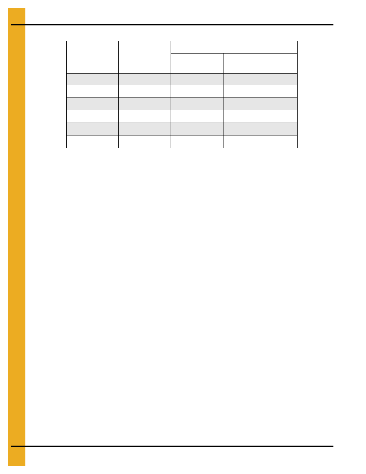
Scribe the Diameter (See Figure 2A.)
After determining the center of the site, drive a small 2 x 4 in the ground to mark the center point of the
foundation. The top of the stake should be the same height as the finished foundation will be. Using one
large spike, nail a straight 2 x 4 (approximately 2' longer than the radius of the bin) to the top of the center
stake. The swiveling 2 x 4 will act as a compass, enabling you to scribe the correct diameter of the
foundation and later locate the anchor and stiffener bolt locations. (NOTE: Making the 2 x 4 two feet (2')
longer than the radius will allow the 2 x 4 to also be used as a leveling device and for pulling concrete.)
Figure 2A Scribe the Diameter
8PNEG-318 Concrete Foundation Recommendations for GSI Grain Bins
Page 9
2. General Foundation Requirements for GSI Bins
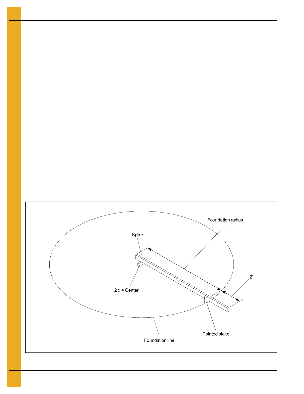
Carpenter’s level
Footing trench
Prepare the Foundation Forms
After scribing the diameter of the foundation, proceed by digging the foundation’s footing. This consists of
a large circular trench dug just inside the foundation line. (Refer to foundation details (frost free pad,
inverted “T” and T-Cap) of corresponding bins and tanks in this manual for necessary information.) Once
the footing has been dug, you are ready to build the forms. It is most important that the form be rigid enough
to hold its shape against the poured concrete. Also, the foundation must be flat. Sloped floors cannot be
used in drying bins. A carpenter’s level placed atop the compass 2 x 4 will enable you to set the top of the
forms to match the top of the center stake.
a uniform elevation for the entire foundation. The foundation should be level within 1/8" on non-stiffened
tanks and 1/4" on stiffened tanks at bin wall perimeter. Stiffened tanks must be shimmed level.
(See Figure 2B.)
Check the form work with a transit to ensure
Figure 2B Level the Forms
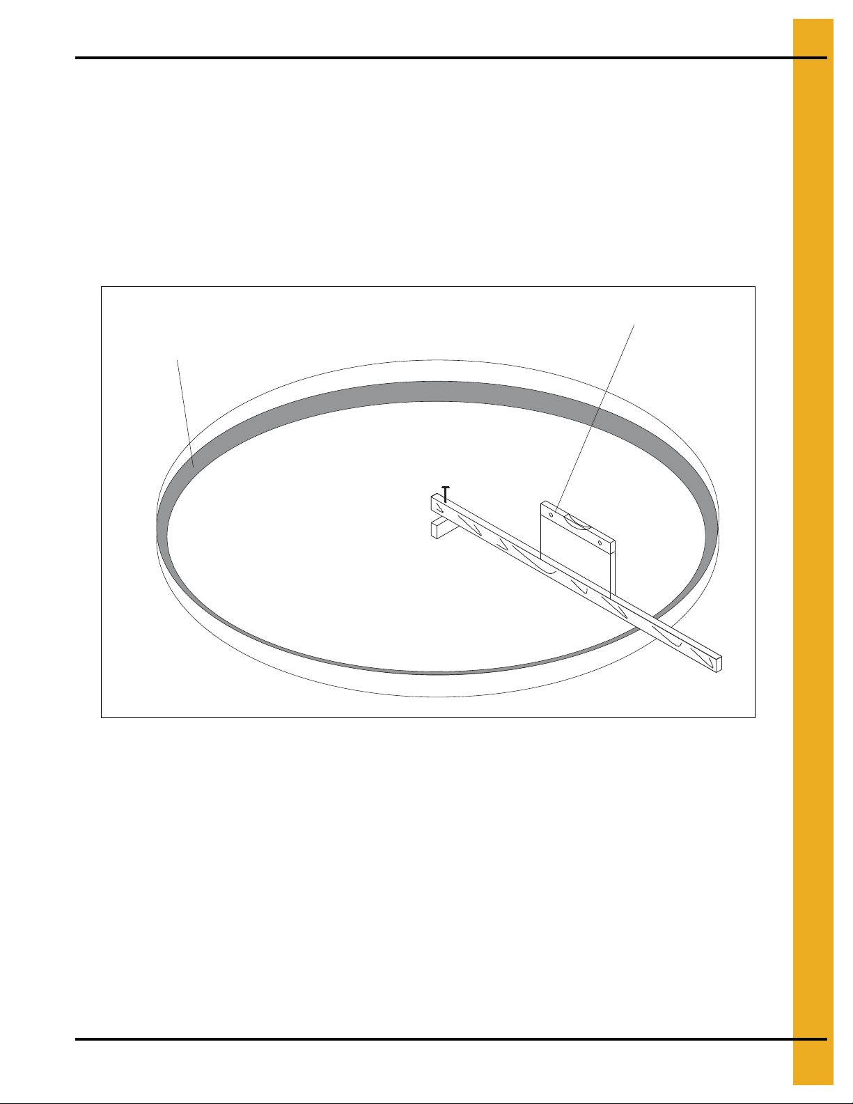
Alternate Foundation Forms
There are two (2) styles of foundation forms commonly used. The first is the circular form shown in
Figure 2B. The second style of foundation can be made of 2" x 8" boards set into a square with the corners
blocked off to form an octagon. (See Figure 2C on Page 10.) This eight (8) sided form will approximate a
circle and can also be constructed easily.
PNEG-318 Concrete Foundation Recommendations for GSI Grain Bins 9
Page 10
2. General Foundation Requirements for GSI Bins
Figure 2C Alternate Foundation Form
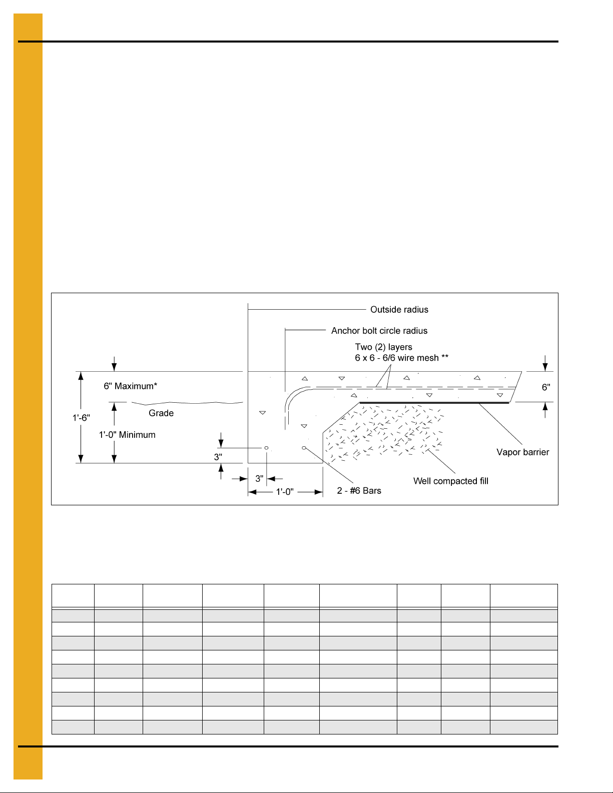
Place the Reinforcement
Once the forms and trench have been prepared, begin the placement of reinforcement rods at various
levels in the foundation’s footing. See the appropriate charts and drawings in this manual for the bin to
determine requirements and positions of the reinforcement. The reinforcement rods offer their greatest
strength when lapped properly and connected by wiring or welding. Next, place a minimum of 2" of
compacted sand on the inside section of the foundation to provide a good base for the concrete and
protect against rodents. The sand should then be covered with 4 mil polyethylene plastic, which will act as
a moisture barrier. Two (2) layers of 6 x 6 wire mesh should then be added to the entire area of the
foundation to complete the preparation of the bin’s foundation.
10 PNEG-318 Concrete Foundation Recommendations for GSI Grain Bins
Page 11
2. General Foundation Requirements for GSI Bins
TR-4734
A = 20" for fans without heaters
A = 44" for fans with heaters
TR-6918 and TR-6919
A = 32" for fans without heaters
A = 56" for fans with heaters
TR-7048
A = 45" for fans without heaters
A = 69" for fans with heaters
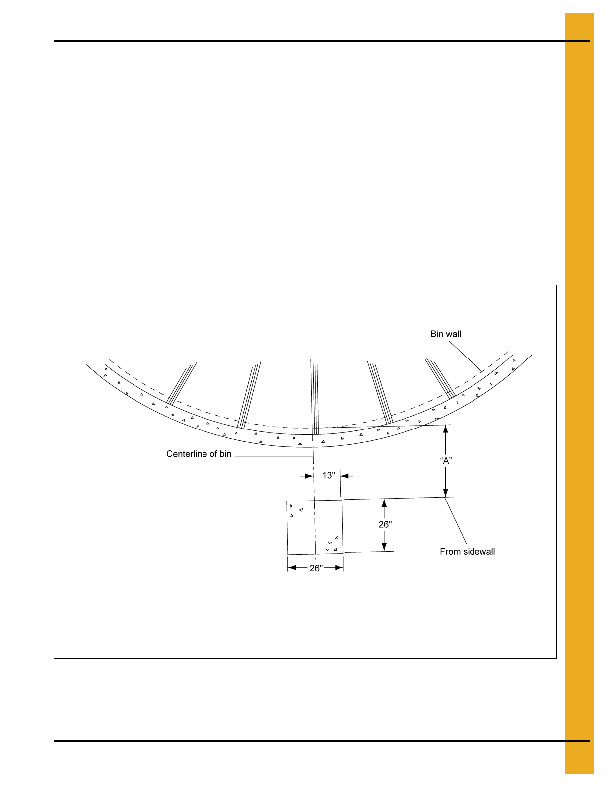
Vane Axial Fan Pad
Placement of the Fan Pad: Transitions/Fans/Heaters Only.
If a fan or fan and heater will be installed, refer to Figure 2D to determine the concrete pad size.
1. The top of this pad should be level with the top of the bin’s foundation.
2. Recommended pad thickness is 4" minimum.
3. Front of pad should be perpendicular to bin wall.
4. Pad for heater not required, but if it is to added, pour the pad to cover both locations.
For fans and transitions used in aeration duct system applications, refer the transition and aeration
installation instructions.
IMPORTANT: Fan pad and fan must be level and smooth for proper operation. Vibration problems can
result from improper fan leveling.
PNEG-318 Concrete Foundation Recommendations for GSI Grain Bins 11
Figure 2D
Page 12
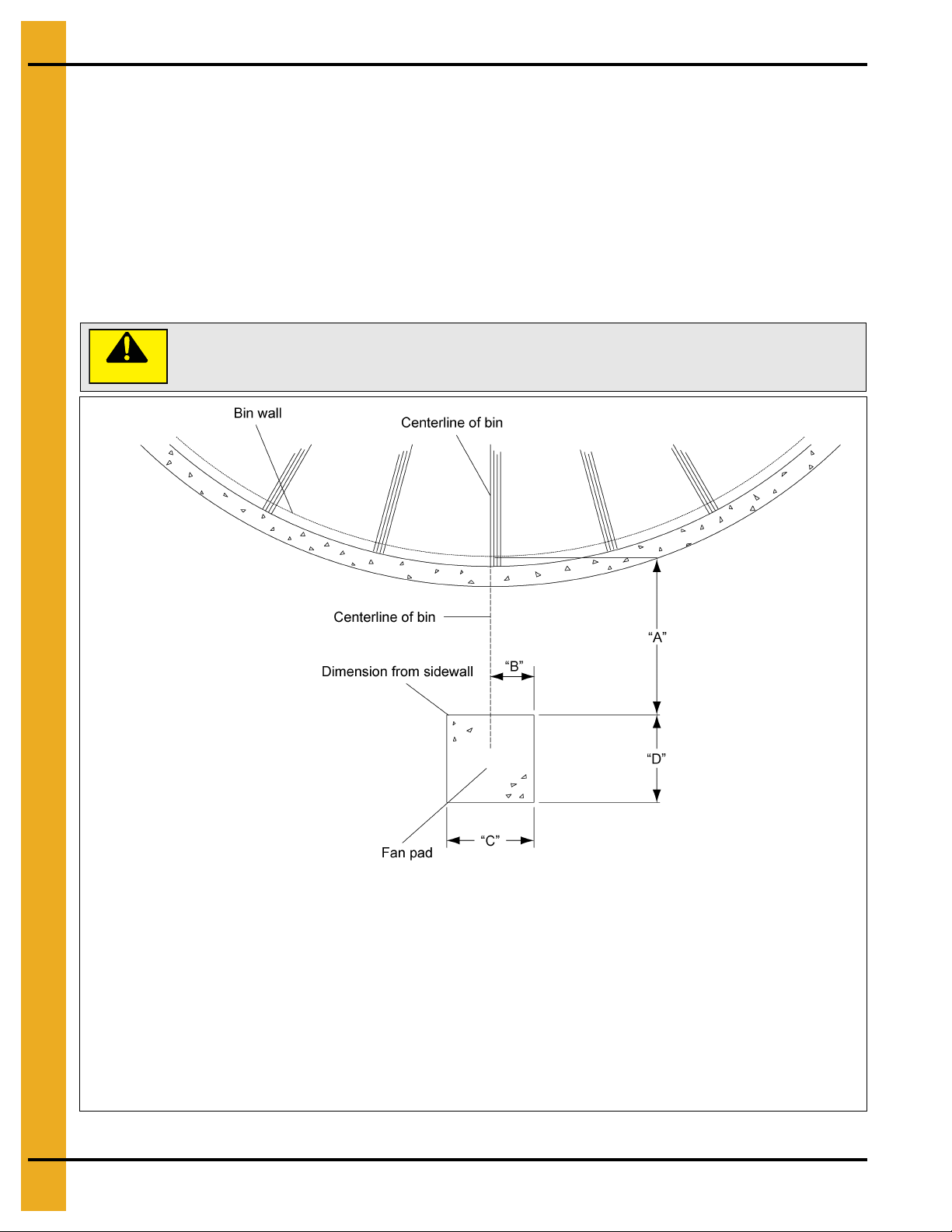
2. General Foundation Requirements for GSI Bins
CAUTION
Fan pad and fan must be level and smooth for proper operation. Vibration
problems can result from improper fan leveling.
Front of pad should be perpendicular to bin wall. Recommended thickness for fan pad is
4" minimum. Surface of pad should be 2" below the bin foundation. Pad for heater not required.
TR-4734
A = 20" without heater
A = 44" with heater
B = 10"
C = 40"
D = 40"
TR-7048
A = 45" without heater
A = 69" with heater
B = 10"
C = 40"
D = 48"
TR-6918 and
TR-6919
A = 32" without heater
A = 65" with heater
B = 13"
C = 48"
D = 52"
TR-7049
A = 45" without heater
A = 78" with heater
B = 13"
C = 48"
D = 52"
TR-6207
A = 42" without heater
A = 78" with heater
B = 13"
C = 48"
D = 60"
TR-6958
A = 55" without heater
A = 85" with heater
B = 13"
C = 48"
D = 60"
TR-6853 (Double inlet)
A = 54" without heater
A = 88" with heater
B = 28"
C = 100"
D = 60"
TR-4013
A = 36" without heater
B = 13"
C = 48"
D = 60"
TR-6944
A = 48" without heater
B = 13"
C = 48"
D = 60"
Centrifugal Fan Pad
1. Fan pad should be poured 2" below the top of the bin foundation for all centrifugal fans.
2. A pad for heaters is not required, but is recommended.
3. Recommended pad thickness is 4".
4. If a downwind heater pad is to be installed, the pad width (“C”) should be 48" and extended toward
the bin by 33".
5. Fan discharge should be centered on centerline of bin.
6. The fan pad should be perpendicular to bin wall.
12 PNEG-318 Concrete Foundation Recommendations for GSI Grain Bins
Figure 2E Centrifugal Fan Pad
Page 13

2. General Foundation Requirements for GSI Bins
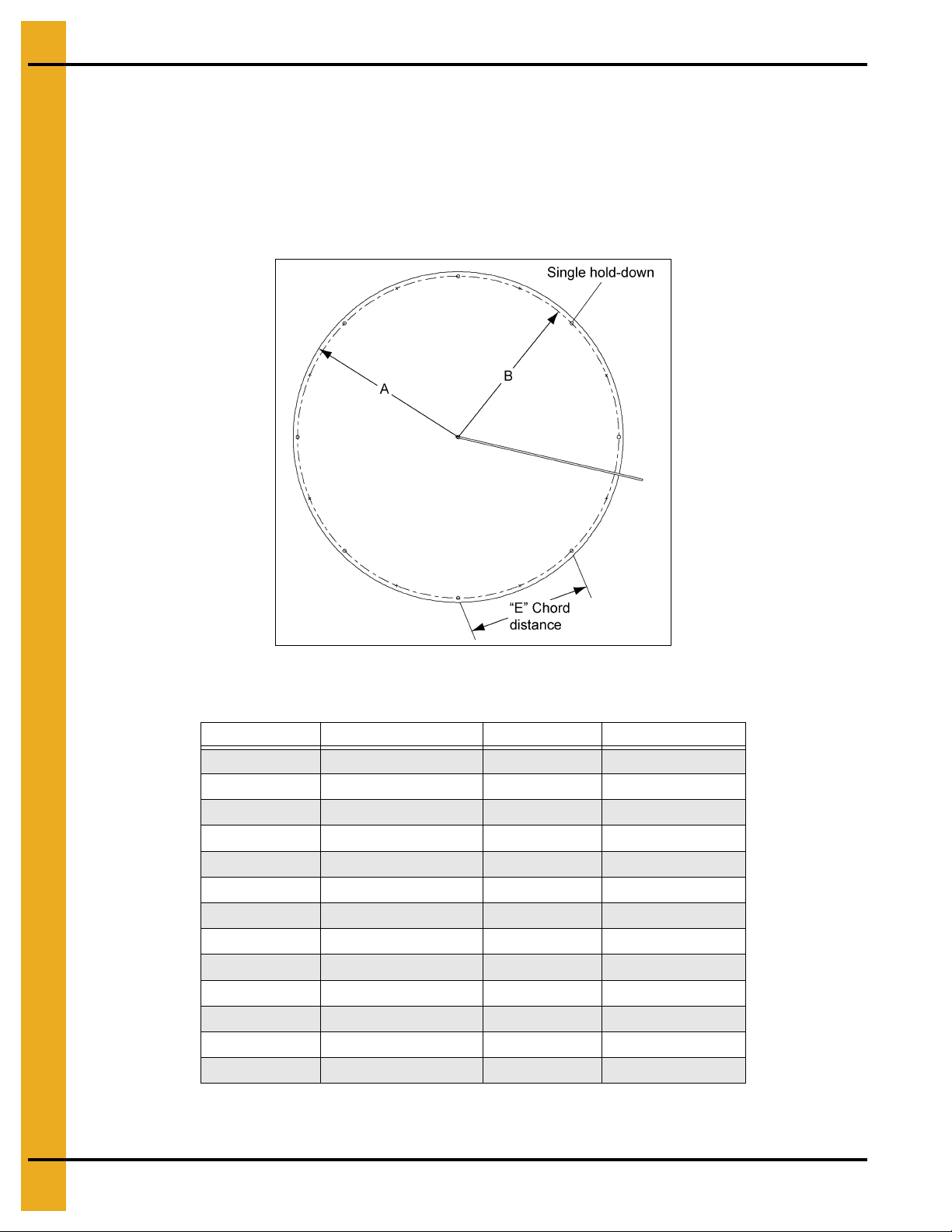
Anchor Bolt Placement
Having poured and leveled the concrete, use the center stake and straight 2 x 4 again to find the bolt circle
radius for the outside hold-down brackets. Select a starting point and stretch a pre-measured chord along
the imaginary circle formed by the bolt circle radius. Take into consideration the placement of these bolts
so as not to interfere with the positions of bin doors and transitions. (Refer to charts on Pages 18-20 for
necessary radii and chord lengths.) Take the time and work carefully: ACCURACY IS IMPORTANT.
FOR STIFFENER ANCHOR BOLT LOCATIONS ON COMMERCIAL TANKS, REFER TO COMMERCIAL
TANK SECTION IN THIS MANUAL OR CALL THE GSI ENGINEERING DEPARTMENT.
NOTE: Top edge of slab where the bin wall sets must be held to within 1/8" of level.
Figure 2F Anchor Bolt Placement
PNEG-318 Concrete Foundation Recommendations for GSI Grain Bins 13
Page 14
2. General Foundation Requirements for GSI Bins
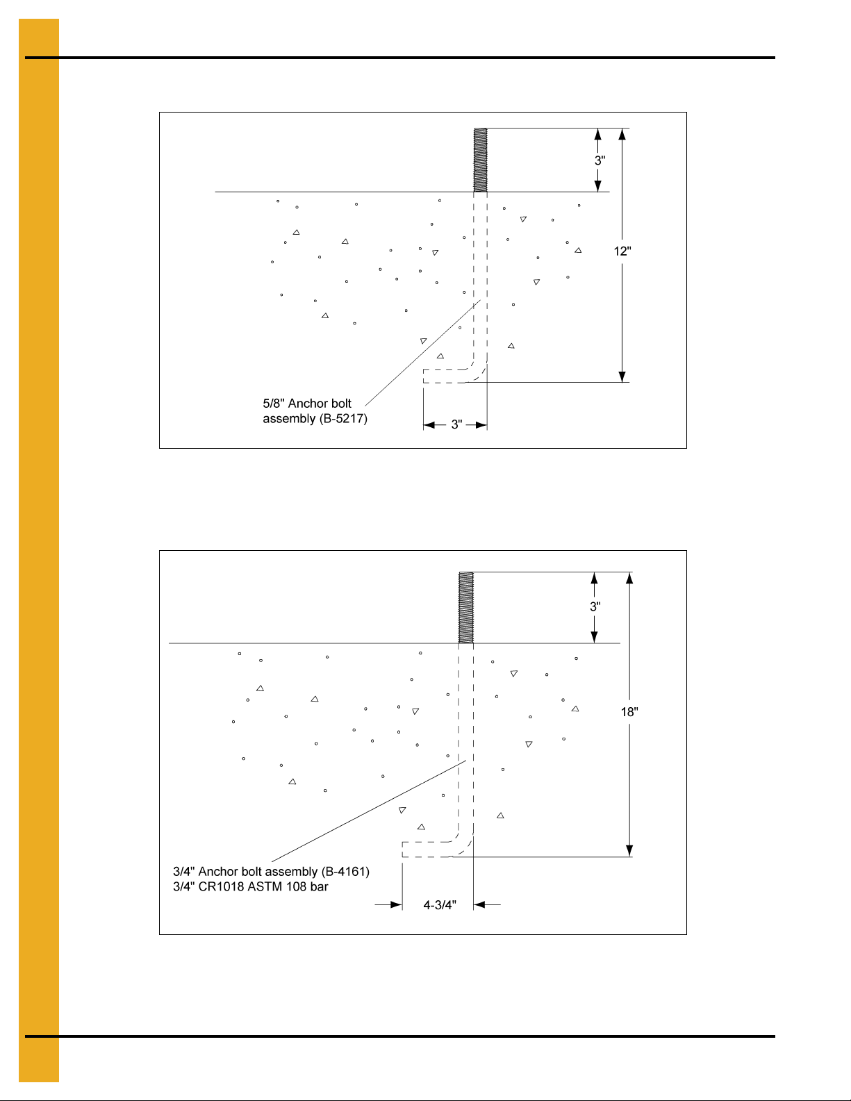
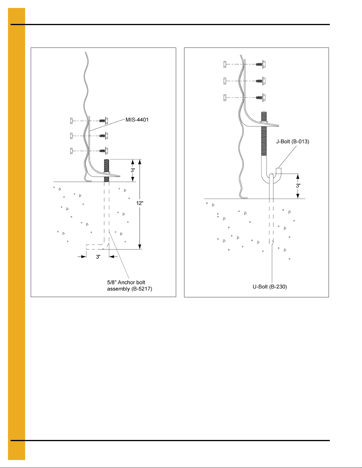
FCDL Anchor Bolt Detail
Figure 2G FCDL Anchor Bolt Detail
Commercial Tank Anchor Bolt Detail
Figure 2H Commercial Tank Anchor Bolt Detail
NOTE: This is a general case anchor b olt detail. Some situations, conditions and storage tanks may have
different anchor bolt or anchoring requirements.
14 PNEG-318 Concrete Foundation Recommendations for GSI Grain Bins
Page 15
2. General Foundation Requirements for GSI Bins
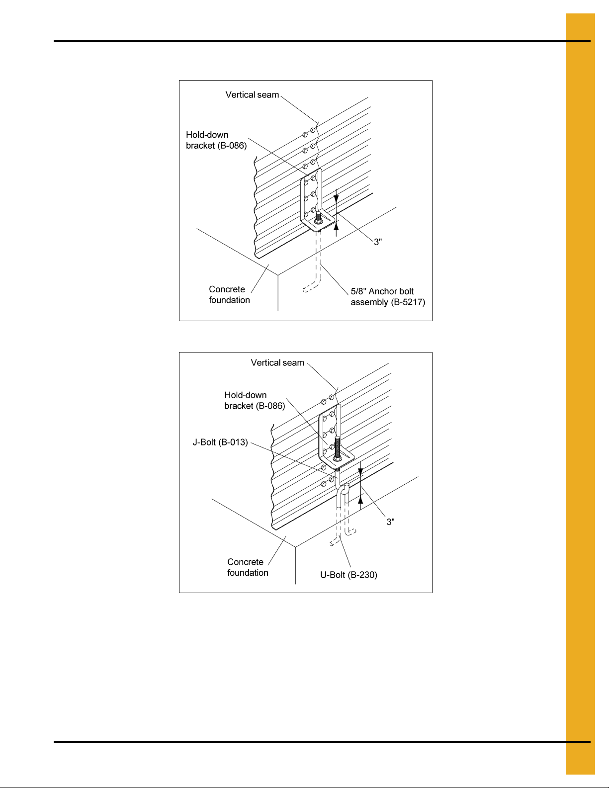
Outside Bin Hold-Down Details (Unstiffened 2.66" Corrugation)
Figure 2I Single Anchor Bolt
Figure 2J U-Bolt/J-Bolt Combination
Outside bin hold-downs should be used on all non-stiffened bins/silos. When anchoring the bin, be sure
the vertical seams of the bin/silo align with the U-bolts or single anchor bolts in the foundation. Bin/silos
up to 36' diameter and 12 rings tall or shorter may be anchored using either the U-bolt/J-bolt combina tion
or the single anchor bolt. Bin/silos 42' and greater in diameter and all 13 rings or taller sh ould be anchored
using the single anchor bolt. Bins/silos 13 rings and taller require double hold-downs. The sidewall must
be field drilled to attach the hold-down bracket located between the horizontal seams. For the case of 42'
and larger bin/silo, no greater than 12 rings tall, double U-bolt/J-bolt combination anchors may be used as
an option to the single anchors bolt. Additional hold-downs are required with this option.
PNEG-318 Concrete Foundation Recommendations for GSI Grain Bins 15
Page 16
2. General Foundation Requirements for GSI Bins
Outside Bin Hold-Down Details (Unstiffened 4.00" Corrugation)
Figure 2K Single Anchor Bolt
Outside bin hold-downs should be used on all non-stiffened GSI bins. When anchoring the bin, be sure
the vertical seams of the bin align with the U-bolts in the foundation. They may be anchored to the
foundation using either the U-bolt and J-bolt combination or the single anchor bolt, except on 42' diameter
and larger bins and bins 10 rings tall.
NOTE: All non-stiffened 42' and larger bins and bins 10 rings tall should use single anchor bolts, not the
U-bolt/J-bolt combination. (Double U-bolt/J-bolt may be used on non-stiffened 42' and larger bins,
no greater than 9 rings tall as an option.)
16 PNEG-318 Concrete Foundation Recommendations for GSI Grain Bins
Figure 2L U-Bolt/J-Bolt Combination
Page 17

FCDL Series
Anchor Bolt Charts
®
Section 03
PNEG-318 Concrete Foundation Recommendations for GSI Grain Bins 17
Page 18
3. FCDL Series Anchor Bolt Charts
The dimensions in this chart on Pages 18-20 apply only to the FCDL series. For WC or NC series
commercial tanks, refer the appropriate section of PNEG-318.
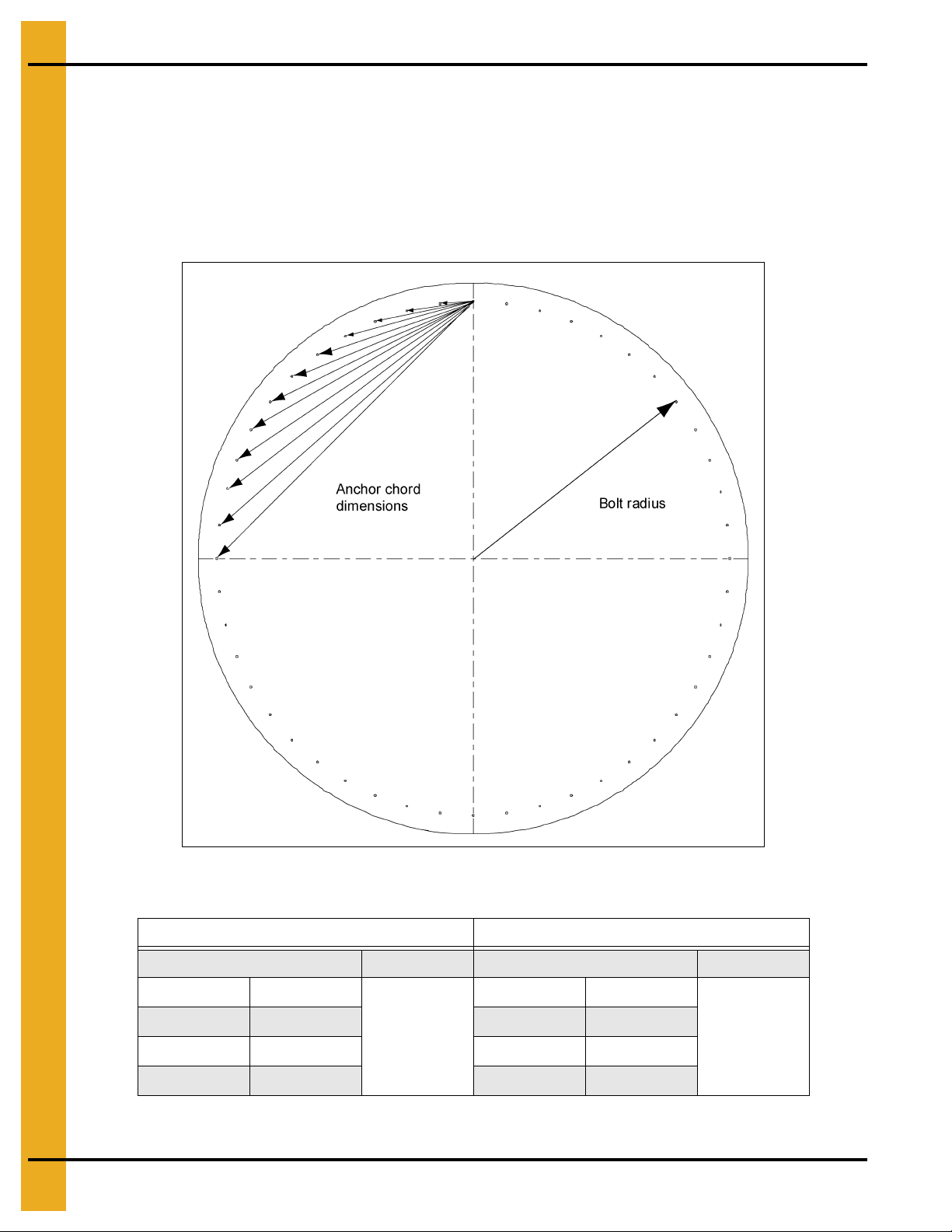
Refer to proper chart on Pages 18-20 to find the anchor chord that corresponds to the bin that is going to
be built.
Start with one anchor bolt and work from it to the left to locate one qua rter of the anchor bolts, then to the
right to locate another quarter of the bolts. Now work off of the last anchor bolt s in each quarter t o lo cate
remaining anchor bolts in the last two (2) quarters.
Figure 3A
Anchor Bolt Charts
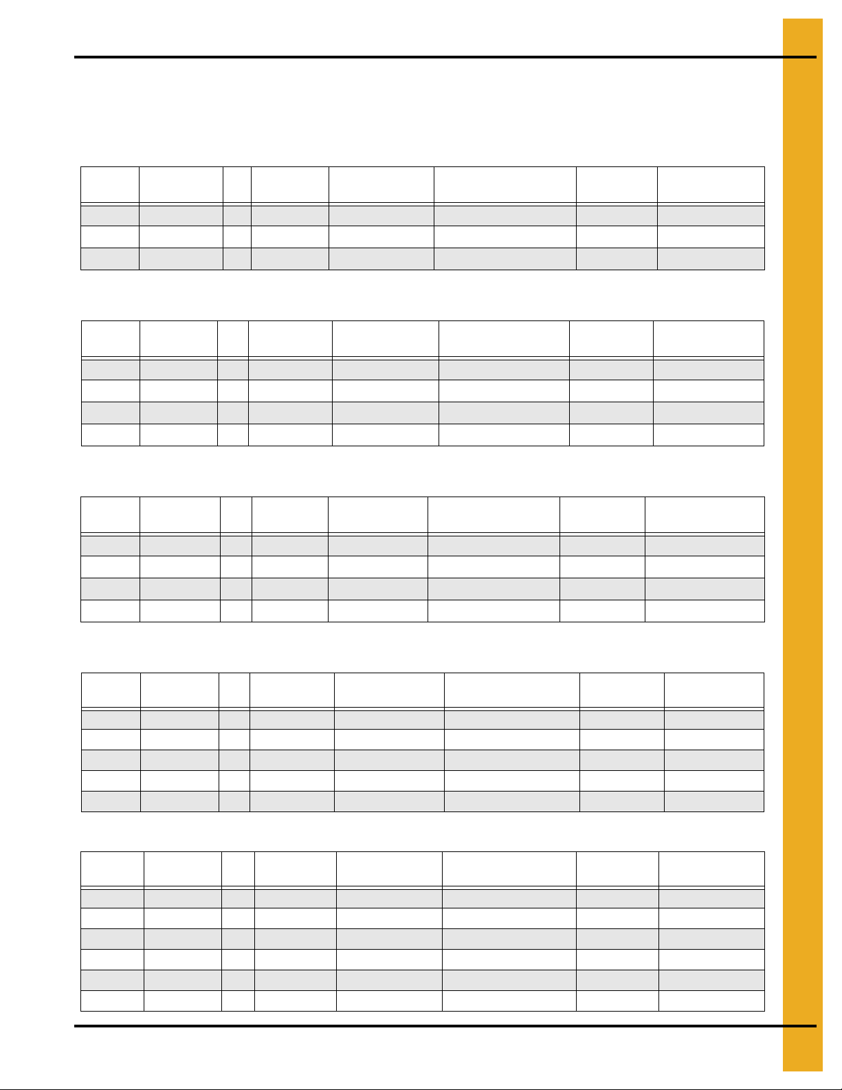
12' Diameter Bin 15' Diameter Bin
Bolt Radius 6' - 3-1/4'' Bolt Qty. 8 Bolt Radius 7' - 9-1/8'' Bolt Qty. 10
Chord # Chord Dist. Chord # Chord Dist.
1 4' - 9-5/8'' 1 4' - 9-9/16''
2 8' - 10-7/16'' 2 9' - 1-1/2''
3 11' - 7-1/16" 3 12' - 6-11/16''
18 PNEG-318 Concrete Foundation Recommendations for GSI Grain Bins
Page 19
3. FCDL Series Anchor Bolt Charts
18' Diameter Bin 21' Diameter Bin
Bolt Radius 9' - 3-1/16'' Bolt Qty. 12 Bolt Radius 10' - 8-15/16" Bolt Qty. 14
Chord # Chord Dist. Chord # Chord Dist.
1 4' - 9-1/2" 1 4' - 9-3/8"
2 9' - 3-1/16" 2 9' - 3-7/8"
3 13' - 1-1/16" 3 13' - 4-13/16"
4 16' - 0-3/8" 4 16' - 9-5/8"
24' Diameter Bin 27' Diameter Bin
Bolt Radius 12' - 2-7/8'' Bolt Qty. 16 Bolt Radius 13' - 8-3/4" Bolt Qty. 18
Chord # Chord Dist. Chord # Chord Dist.
1 4' - 9-5/16" 1 4' - 9-3/16"
2 9' - 4-7/16" 2 9' - 4-11/16"
3 13' - 7-3/16" 3 13' - 8-3/4"
4 17' - 3-11/16" 4 17' - 7-13/16"
5 20' - 4-1/4" 5 21'-7/16"
30' Diameter Bin 33' Diameter Bin
Bolt Radius 15' - 2-11/16'' Bolt Qty. 20 Bolt Radius 16' - 8-9/16" Bolt Qty. 22
Chord # Chord Dist. Chord # Chord Dist.
1 4' - 9-3/16" 1 4' - 9-1/16"
2 9' - 4-15/16" 2 9'-5"
3 13' - 9-7/8" 3 13' - 10-5/8"
4 17' - 10-3/4" 4 18'-7/8"
5 21' - 6-3/8" 5 21' - 10-11/16"
6 24' - 7-5/8" 6 25' - 3-1/8"
36' Diameter Bin 42' Diameter Bin
Bolt Radius 18' - 2-1/2'' Bolt Qty. 24 Bolt Radius 21' - 2-5/16'' Bolt Qty. 28
Chord # Chord Dist. Chord # Chord Dist.
1 4' - 9-1/16" 1 4 ' - 8-15/16"
2 9' - 5-1/8" 2 9' - 5-3/16"
3 13' - 11-1/4" 3 14'-0"
4 18' - 2-1/2" 4 1 8' - 4-11/16"
5 22'-2" 5 22' - 6-5/8"
6 25'-9" 6 26' - 5-1/8"
7 28' - 10-11/16" 7 29' - 11-5/8"
8 31' - 6-7/16" 8 33' - 1-11/16"
PNEG-318 Concrete Foundation Recommendations for GSI Grain Bins 19
Page 20
3. FCDL Series Anchor Bolt Charts
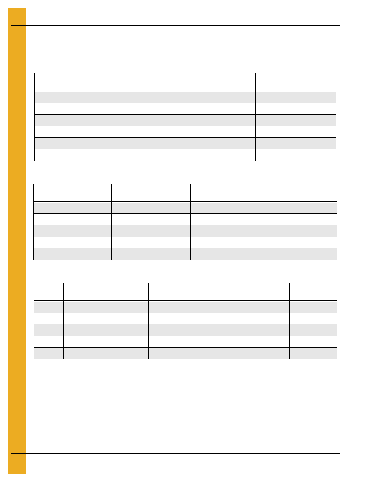
48' Diameter Bin 54' Diameter Bin
Bolt Radius 24' - 2-1/8'' Bolt Qty. 32 Bolt Radius 27' - 1-15/16'' Bolt Qty. 36
Chord # Chord Dist. Chord # Chord Dist.
1 4' - 8-7/8" 1 4' - 8-13/16"
2 9' - 5-3/16" 2 9' - 5-3/16"
3 14' - 7/16" 3 14' - 11/16"
4 18' - 6-1/16" 4 18' - 6-15/16"
5 22' - 9-1/2" 5 22' - 11-1/2"
6 26' - 10-3/8" 6 27' - 1-15/16"
7 30' - 8-1/8" 7 31' - 1-7/8"
8 34' - 2-5/16" 8 34'-11"
9 37' - 4-9/16"
Bolt Radius 30' - 1-3/4" Bolt Qty. 40
Chord # Chord Dist.
1 4' - 8-3/4"
2 9' - 5-3/16"
3 14'-7/8"
4 18' - 7-9/16"
5 23'-7/8"
6 27' - 4-7/16"
7 31'-6"
8 35' - 5-1/4"
9 39' - 1-7/8"
10 42' - 7-9/16"
11 45' - 10-1/8"
9 38' - 4-15/16"
10 41' - 7-3/8"
60' Diameter Bin
Figure 3B Anchor Bolt Detail (Typical)
20 PNEG-318 Concrete Foundation Recommendations for GSI Grain Bins
Page 21

Floating Monolithic Pad Recommendations
for FCDL and FCRL Series Bins
®
Section 04
PNEG-318 Concrete Foundation Recommendations for GSI Grain Bins 21
Page 22
4. Monolithic Pad FCDL
All foundation specifications shall be
construed as recommendations only. Because
of the many variable conditions in actual
installation, GSI assumes no liability for results
arising from the use of such recommendations.
Floating Monolithic Pad for GSI FCDL Bins up to 5 Rings
Monolithic Pad Notes:
1. The foundation design is based on a minimum allowable soil bearing capacity of 3000 PSF.
Bearing capacity of the soils should be determined by geotechnical investigation and be of uniform
bearing capacity.
2. The foundation site must be free of vegetation and debris and well drained.
3. The foundation must be founded below the frost line or constructed on non-expansive frost free fill.
4. All material used for backfill inside the ring wall should be clean, well graded, crushed rock or a
sand-gravel mixture. Backfill should be placed in 6" lifts, 95% compaction.
5. All reinforcement must meet the requirements of ASTM A615 grade 60 deformed bars.
6. Lap all circumferential bars 35 bar diameters and stagger all laps in plans 3'-0". Estimates do not
include end laps.
7. Concrete must have a minimum compressive strength of 3000 PSI at 28 days, 6%-8% air
entrainment, 4" slump.
Figure 4A
* Contact GSI Engineering for heights greater than 6".
** The optional #4 rebar grid can be substituted for the wire mesh in most cases. Place the #4 bars
in the pad at 18" c/c each way.
Bin
Diameter
12' 6'-9'' 6' - 3-1/4'' 4' - 9-5/8'' 8 4.5 300 100 200
15' 8'-3'' 7' - 9-1/8'' 4' - 9-9/16'' 10 6 500 100 300
18' 9'-9'' 9' - 3-1/16'' 4' - 9-1/2'' 12 8 700 200 400
21' 11'-3'' 10' - 8-15/16'' 4' - 9-3/8'' 14 10 900 200 600
24' 12'-9" 12' - 2-7/8'' 4' - 9-5/16'' 16 12-1/2 1100 200 700
27' 14'-3" 13' - 8-3/4'' 4' - 9-3/16'' 18 15 1200 200 900
30' 15'-9'' 15' - 2-11/16'' 4' - 9-3/16'' 20 18 1600 200 1100
33' 17'-3'' 16' - 8-9/16'' 4' - 9-1/16'' 22 21-1/2 1800 300 1300
36' 18'-9'' 18' - 2-1/2'' 4' - 9-1/16'' 24 25 2300 300 1500
22 PNEG-318 Concrete Foundation Recommendations for GSI Grain Bins
Outside
Radius
Single Bolt
Radius
Anchor Chord # of Anchors
Total Cu. Yds.
Concrete
Sq. Ft.
Mesh
Length #6
Bar
Optional #4
Grid (ft.)
Page 23

Frost Free Pad Recommendations
for FCDL and FCRL Series Bin
®
Section 05
PNEG-318 Concrete Foundation Recommendations for GSI Grain Bins 23
Page 24
5. Frost Free Pad FCDL
Anchor Bolt Placement
Having poured and leveled the concrete, use the center stake and straight 2 x 4 again to find the bolt circle
radius for the outside hold-down brackets. Select a starting point and stretch a pre-measure d chord along
the imaginary circle formed by the bolt circle radius. Take into consideration the placement of these bolts
so as not to interfere with the positions of bin doors and transitions. (Refer to following chart below for
necessary radii and chord lengths.) Take the time and work carefully since accuracy is important.
NOTE: Top edge of slab where the bin wall sets must be held to within 1/8" of level.
Figure 5A
NOTE: Refer to chapter 4 on Page 21 for additional anchor details.
Bin Diameter “B” Bolt Circle Radius # of Anchors “E” Chord Distance
12' 6' - 3-1/4" 8 4' - 9-5/8"
15' 7' - 9-1/8" 10 4' - 9-9/16"
18' 9' - 3-1/16" 12 4' - 9-1/2"
21' 10' - 8-15/16" 14 4' - 9-3/8"
24' 12' - 2-7/8" 16 4' - 9-5/16"
27' 13' - 8-3/4" 18 4' - 9-3/16"
30' 15' - 2-11/16" 20 4' - 9-3/16"
33' 16' - 8-9/16" 22 4' - 9-1/16"
36' 18' - 2-1/2" 24 4' - 9-1/16"
42' 21' - 2-5/16" 28 4' - 8-15/16"
48' 24' - 2-1/8" 32 4' - 8-7/8"
54' 27' - 1-15/16" 36 4' - 8-3/16"
60' 30' - 1-3/4" 40 4' - 8-3/4"
For stiffener anchor bolt locations on commercial tanks, refer to commercial tank section found later in this
manual or call the GSI engineering department.
24 PNEG-318 Concrete Foundation Recommendations for GSI Grain Bins
Page 25
5. Frost Free Pad FCDL
All foundation specifications shall be construed as
recommendations only. Because of the many
variable conditions in actual installation, GSI
assumes no liability for results arising from the
use of such recommendations.
Frost Free Pad Notes:
1. The foundation design is based on a minimum allowable soil bearing capacity of 3000 PSF.
Bearing capacity of the soils should be determined by geotechnical investigation and be of uniform
bearing capacity.
2. The foundation site must be free of vegetation and debris and well drained.
3. The foundation must be founded below the frost line or constructed on non-expansive frost free fill.
4. All material used for backfill inside the ring wall should be clean, well graded, crushed rock or a
sand-gravel mixture. Backfill should be placed in 6" lifts, 95% compaction.
5. All reinforcement must meet the requirements of ASTM A615 grade 60 deformed bars.
6. Lap all circumferential bars 35 bar diameters and stagger all laps in plans 3'-0". Estimates do not
include end laps.
7. Concrete must have a minimum compressive strength of 3000 PSI at 28 days, 6%-8% air
entrainment, 4" slump.
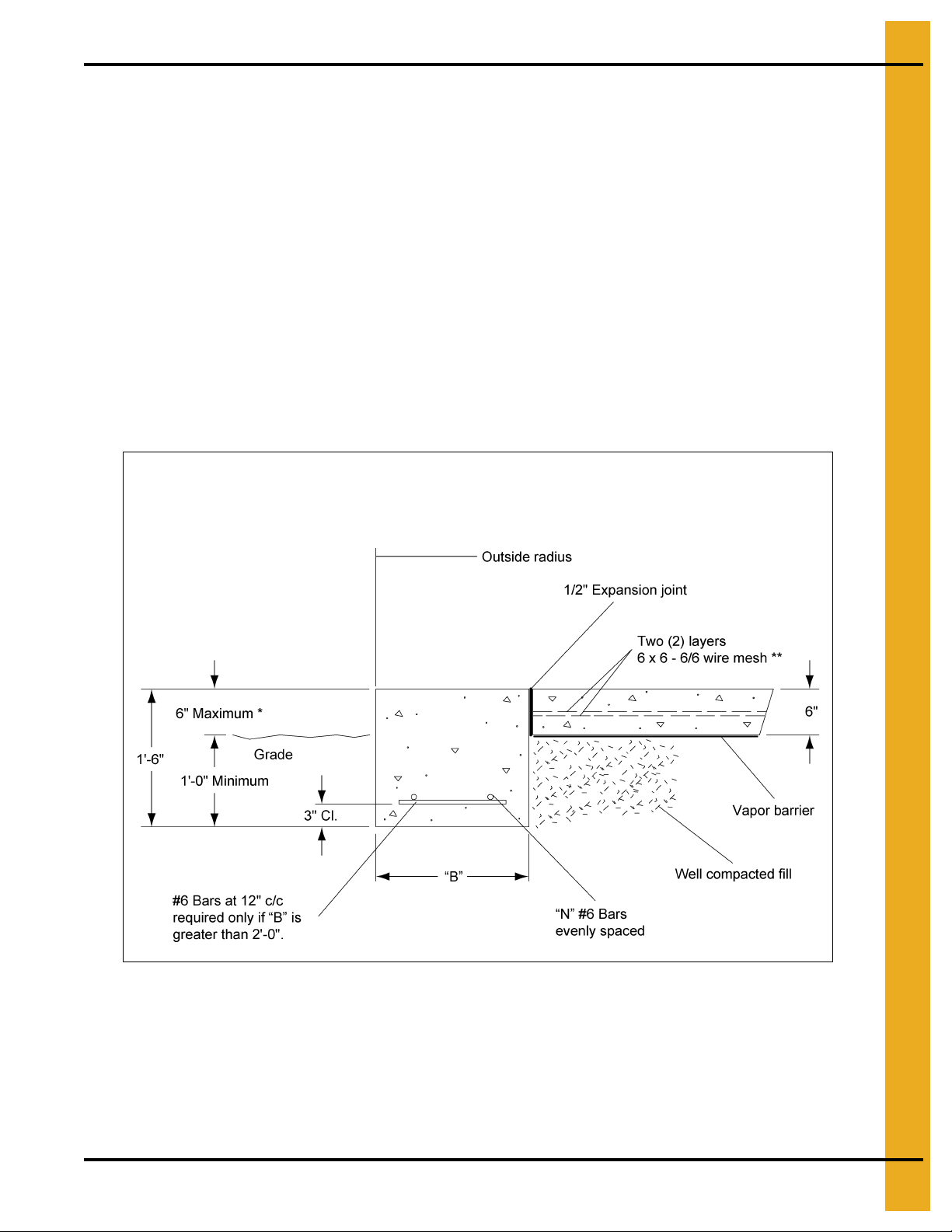
* Contact GSI Engineering for heights greater than 6".
** The optional #4 rebar grid can be substituted for the wire mesh in most ca ses. Place the #4 bars
in the pad at 18" c/c each way.
PNEG-318 Concrete Foundation Recommendations for GSI Grain Bins 25
Figure 5B
Page 26
5. Frost Free Pad FCDL
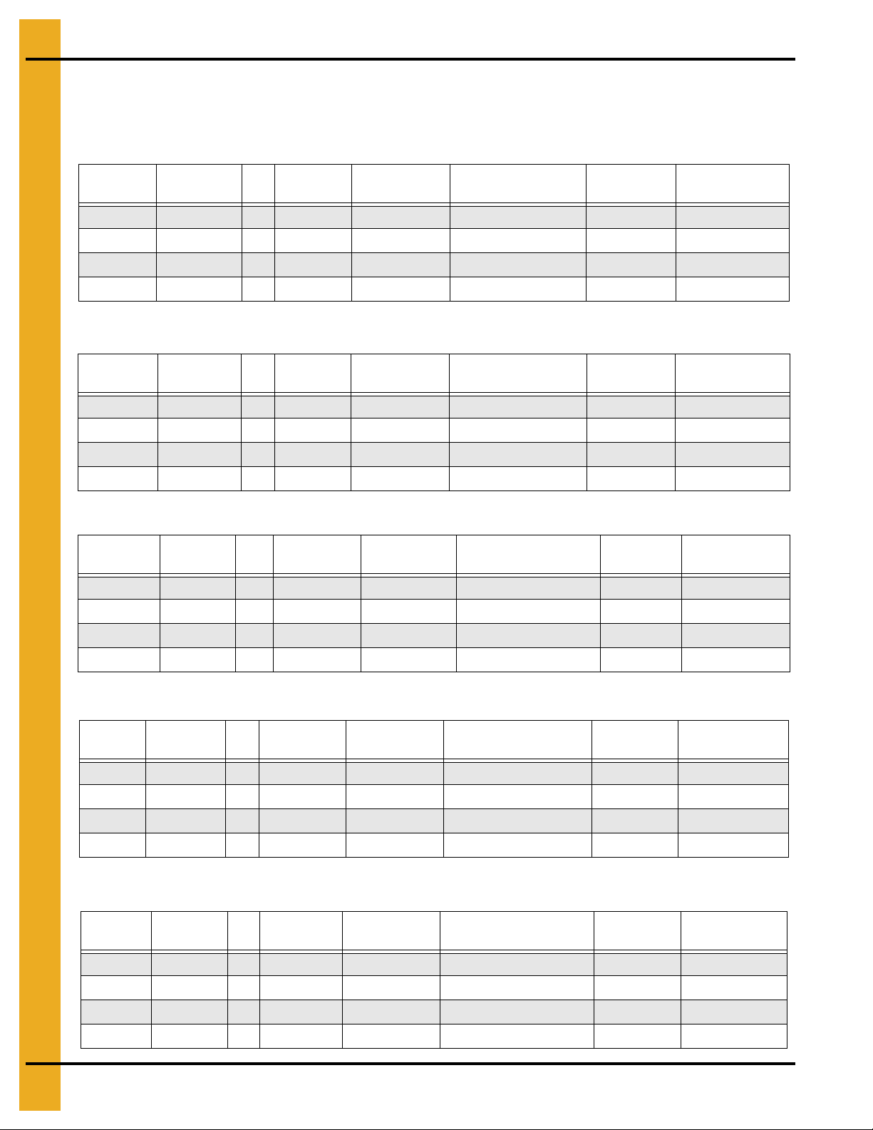
Frost Free Pad (FCDL Bins)
(Refer to Figure 5A on Page 24.)
Diameter of Bin: 12'
Corrugation: 4.00"
Ring # B N
6 1 ft. 0 in. 2 6 f t. 9 in. 300 200 100 5
7, 8 1 ft. 7 in. 2 6 ft. 9 in. 300 200 100 5
9, 10 2 ft. 0 in. 2 7 ft. 0 in. 300 200 200 6
1 1, 12 2 ft. 10 in. 3 7 ft. 6 in. 300 200 300 8
Diameter of Bin: 15'
Corrugation: 4.00''
Ring # B N
6 1 ft. 0 in. 2 8 ft. 3 in. 400 300 100 6
7, 8 1 ft. 7 in. 2 8 ft. 3 in. 400 300 100 7
9, 10 2 ft. 0 in. 2 8 ft. 7 in. 400 300 200 8
11, 12 2 ft. 0 in. 2 8 ft. 7 in. 400 300 200 8
Outside
Radius
Outside
Radius
Sq. Ft. Mesh
6 x 6 - 6/6
Sq. Ft. Mesh
6 x 6 - 6/6
Optional #4
18" x 18" Grid (ft.)
Optional #4
18'' x 18'' Grid (ft.)
Length #6
Bar (ft.)
Length #6
Bar (ft.)
Total Cu. Yds.
Concrete
Total Cu. Yds.
Concrete
Diameter of Bin: 18'
Corrugation: 4.00''
Ring # B N
6 1 ft. 0 in. 2 9 ft. 9 in. 500 400 200 8
7, 8 1 ft. 7 in. 2 9 ft. 9 in. 500 400 200 9
9 2 ft. 0 in. 2 10 ft. 1 in. 500 400 200 11
11, 12 2 ft. 6 in. 3 10 ft. 6 in. 5 00 400 300 12
Diameter of Bin: 21'
Corrugation: 4.00''
Ring # B N
6 1 ft. 1 in. 2 11 ft. 3 in. 700 500 200 11
7, 8 1 ft. 7 in. 2 11 ft. 3 in. 700 500 200 12
9, 10 2 ft. 0 in. 2 11 ft. 6 in. 700 500 300 13
1 1 , 12 2 ft. 6 in. 3 11 ft. 9 in. 700 500 400 15
Diameter of Bin: 24'
Corrugation: 4.00''
Ring # B N
6 1 ft. 1 in. 2 12 ft. 9 in. 900 600 200 13
7, 8 1 ft. 9 in. 2 12 ft. 9 in. 900 600 200 15
Outside
Radius
Outside
Radius
Outside
Radius
Sq. Ft. Mesh
6 x 6 - 6/6
Sq. Ft. Mesh
6 x 6 - 6/6
Sq. Ft. Mesh
6 x 6 - 6/6
Optional #4
18'' x 18'' Grid (ft.)
Optional #4
18'' x 18'' Grid (ft.)
Optional #4
18'' x 18'' Grid (ft.)
Length #6
Bar (ft.)
Length #6
Bar (ft.)
Length #6
Bar (ft.)
Total Cu. Yds.
Total Cu. Yds.
Concrete
To tal Cu. Yds.
Concrete
Concrete
9, 10 2 ft. 6 in. 3 13 ft. 2 in. 900 600 400 18
11, 12 2 ft. 9 in. 3 13 ft. 4 in. 900 600 500 18
26 PNEG-318 Concrete Foundation Recommendations for GSI Grain Bins
Page 27
5. Frost Free Pad FCDL
Frost Free Pad (FCDL Bins) (Continued)
(Refer to Figure 5A on Page 24.)
Diameter of Bin: 27'
Corrugation: 4.00''
Ring # B N
6 1 ft. 2 in. 2 14 ft. 3 in. 1100 800 200 16
7, 8 1 ft. 10 in. 2 14 ft. 4 in. 1100 800 200 18
9, 10 2 ft. 7 in. 3 14 ft. 7 in. 1100 800 500 21
Diameter of Bin: 30'
Corrugation: 4.00"
Ring # B N
6 1 ft. 2 in. 2 15 ft. 9 in. 1400 900 200 19
7, 8 1 ft. 10 in. 2 15 ft. 10 in. 1400 900 200 21
9, 10 2 ft. 8 in. 3 16 ft. 1 in. 1400 900 500 25
11, 12 3 ft. 8 in. 4 16 ft. 5 in. 1400 900 700 29
Outside
Radius
Outside
Radius
Sq. Ft. Mesh
6 x 6 - 6/6
Sq. Ft. Mesh
6 x 6 - 6/6
Optional #4
18'' x 18'' Grid (ft.)
Optional #4
18" x 18" Grid (ft.)
Length #6
Bar (ft.)
Length #6
Bar (ft.)
T otal Cu. Yds.
Concrete
Total Cu. Yds.
Concrete
Diameter of Bin: 33'
Corrugation: 4.00"
Ring # B N
6 1 ft. 3 in. 2 17 ft. 3 in. 1700 1100 300 23
7, 8 1 ft. 11 in. 2 17 ft. 4 in. 1700 1100 300 25
9, 10 2 ft. 9 in. 3 17 ft. 6 in. 1700 1100 600 29
11, 12 3 ft. 10 in. 4 18 ft. 0 in. 1700 1100 800 34
Diameter of Bin: 36'
Corrugation: 4.00"
Ring # B N
6 1 ft. 3 in. 2 18 ft. 9 in. 2000 1300 300 26
7, 8 2 ft. 0 in. 2 18 ft. 11 in. 2000 1300 400 30
9, 10 2 ft. 10 in. 3 19 ft. 0 in. 2000 1300 600 33
11, 12 3 ft. 11 in. 4 19 ft. 6 in. 2000 1300 900 39
13 4 ft. 10 in. 5 19 ft. 9 in. 2000 1300 1100 43
Diameter of Bin: 42'
Corrugation: 4.00"
Ring # B N
6 1 ft. 4 in. 2 21 ft. 8 in. 2600 1800 300 34
7, 8 2 ft. 1 in. 3 21 ft. 11 in. 2600 1 800 700 39
9 3 ft. 1 in. 4 22 ft. 2 in. 2600 1800 900 44
10, 11 4 ft. 2 in. 5 22 ft. 7 in. 2600 1800 1200 50
12, 13 4 ft. 10 in. 5 22 ft. 11 in. 2600 1800 1300 54
14 5 ft. 6 in. 6 23 ft. 2 in. 2600 1800 1500 66
Outside
Radius
Outside
Radius
Outside
Radius
Sq. Ft. Mesh
6 x 6 - 6/6
Sq. Ft. Mesh
6 x 6 - 6/6
Sq. Ft. Mesh
6 x 6 - 6/6
Optional #4
18" x 18" Grid (ft.)
Optional #4
18" x 18" Grid (ft.)
Optional #4
18" x 18" Grid (ft.)
Length #6
Bar (ft.)
Length #6
Bar (ft.)
Length #6
Bar (ft.)
Total Cu. Yds.
Concrete
Total Cu. Yds.
Concrete
Total Cu. Yds.
Concrete
PNEG-318 Concrete Foundation Recommendations for GSI Grain Bins 27
Page 28
5. Frost Free Pad FCDL
Frost Free Pad (FCDL Bins) (Continued)
(Refer to Figure 5A on Page 24.)
Diameter of Bin: 48'
Corrugation: 4.00"
Ring # B N
6 1 ft. 5 in. 2 24 ft. 8 in. 3400 2300 400 44
7, 8 2 ft. 3 in. 3 24 ft. 11 in. 3400 2300 800 49
9 3 ft. 3 in. 4 25 ft. 2 in. 3400 2300 1100 55
10, 11 4 ft. 5 in. 5 25 ft. 8 in. 3400 2300 1400 63
12, 13 5 ft. 1 in. 5 25 ft. 11 in. 3400 2300 1500 67
14 5 ft. 8 in. 6 26 ft. 2 in. 5400 2300 1700 72
Diameter of Bin: 54'
Corrugation: 4.00"
Ring # B N
6 1 ft. 5 in. 2 27 ft. 9 in. 4800 3300 400 56
7, 8 2 ft. 3 in. 3 28 ft. 1 in. 4800 3300 600 63
9, 10 3 ft. 3 in. 4 28 ft. 4 in. 4800 3300 700 69
11, 12 4 ft. 5 in. 4 28 ft. 7 in. 4800 3300 1400 75
13, 14 6 ft. 0 in. 6 29 ft. 2 in. 4800 3300 1900 87
Outside
Radius
Outside
Radius
Sq. Ft. Mesh
6 x 6 - 6/6
Sq. Ft. Mesh
6 x 6 - 6/6
Optional #4
18" x 18" Grid (ft.)
Optional #4
18" x 18" Grid (ft.)
Length #6
Bar (ft.)
Length #6
Bar (ft.)
Total Cu. Y ds.
Concrete
Total Cu. Yds.
Concrete
Diameter of Bin: 60'
Corrugation: 4.00"
Ring # B N
6 1 ft. 6 in. 2 30 ft. 7 in. 5400 3600 400 65
7, 8 2 ft. 10 in. 3 31 ft. 3 in. 5400 3600 1100 77
9, 10 3 ft. 8 in. 4 31 ft. 7 in. 5400 3600 1400 82
11, 12 4 ft. 7 in. 5 31 ft. 9 in. 5400 3600 1700 91
13 6 ft. 1 in. 6 32 ft. 4 in. 5400 3600 2200 103
Outside
Radius
Sq. Ft. Mesh
6 x 6 - 6/6
Optional #4
18" x 18" Grid (ft.)
Length #6
Bar (ft.)
Total Cu. Yds.
Concrete
28 PNEG-318 Concrete Foundation Recommendations for GSI Grain Bins
Page 29

Inverted “T” Foundation
Recommendations for
FCDL and FCRL Series Bin
®
Section 06
PNEG-318 Concrete Foundation Recommendations for GSI Grain Bins 29
Page 30
6. Inverted “T” FCDL
All foundation shall be construed as recommendations
only. Because of the many variable conditions in
actual installation, GSI assumes no liability for results
arising from the use of such recommendations.
3000 PSF Soil Bearing Capacity
Inverted “T” Foundation Notes:
1. The foundation design is based on a minimum allowable soil bearing capacity of 3000 PSF.
Bearing capacity of the soils should be determined by geotechnical investigation and be of uniform
bearing capacity.
2. The foundation site must be free of vegetation and debris and well drained.
3. The foundation must be founded below the frost line or constructed on non-expansive frost free fill.
4. All material used for backfill inside the ring wall should be clean, well graded, crushed rock or a
sand-gravel mixture. Backfill should be placed in 6" lifts, 95% compaction.
5. All reinforcement must meet the requirements of ASTM A615 grade 60 deformed bars.
6. Lap all circumferential bars 35 bar diameters and stagger all laps in plans 3'-0". Estimates do not
include end laps.
7. Concrete must have a minimum compressive strength of 3000 PSI at 28 days, 6%-8% air
entrainment, 4" slump.
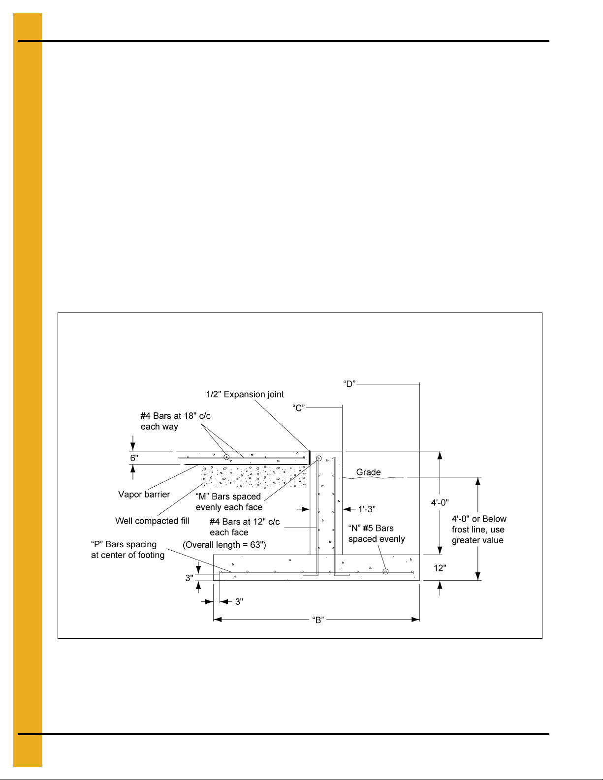
Figure 6A Inverted “T” Foundation
30 PNEG-318 Concrete Foundation Recommendations for GSI Grain Bins
Page 31

6. Inverted “T” FCDL
Inverted “T” Foundations
(Refer to Figure 6A on Page 30.)
Diameter of Bin: 18'
Ring # B C D M N P #4 Bar (ft.) #5 Bar (ft.)
6 1'-3" 9'-8" 9'-8" 5 #4's 2 #5's #5 @ 14" c/c 1600 300 18
7, 8 1'-7" 9'-8" 9'-10" 5 #4's 2 #5's #5 @ 14" c/c 1600 300 19
9, 10 2'-2" 9'-8" 10'-1" 5 #4's 3 #5's #5 @ 14" c/c 1600 300 20
11, 12 2'-4" 9'-8" 10'-2" 5 #4's 3 #5's #5 @ 14" c/c 1600 300 21
Diameter of Bin: 21'
Ring # B C D M N P #4 Bar (ft.) #5 Bar (ft.)
6 1'-3" 11'-2" 11'-2" 5 #4's 2 #5's #5 @ 14" c/c 2000 300 22
7, 8 1'-8" 11'-2" 11'-4" 5 #4's 2 #5's #5 @ 14" c/c 2000 300 23
9, 10 2'-3" 11'-2" 11'-7" 5 #4's 3 #5's #5 @ 14" c/c 2000 400 25
11, 12 2'-6" 11'-2" 11'-8" 5 #4's 3 #5's #5 @ 14" c/c 2000 400 27
Diameter of Bin: 24'
Ring # B C D M N P #4 Bar (ft.) #5 Bar (ft.)
6 1'-3" 12'-8" 12'-8" 5 #4's 2 #5's #5 @ 14" c/c 2300 300 26
7, 8 1'-9" 12'-8" 13'-1" 5 #4's 2 #5's #5 @ 14" c/c 2300 300 27
9 2'-5" 12'-8" 13'-2" 5 #4's 3 #5's #5 @ 14" c/c 2300 500 29
10, 11 2'-8" 12'-8" 13'-4" 5 #4's 3 #5's #5 @ 14" c/c 2300 500 31
Cu. Yds.
Concrete
Cu. Yds.
Concrete
Cu. Yds.
Concrete
Diameter of Bin: 27'
Ring # B C D M N P #4 Bar (ft.) #5 Bar (ft.)
6 1'-3" 14'-2" 14'-2" 5 #4's 2 #5's #5 @ 14" c/c 2600 300 31
7, 8 1'-10" 14'-2" 14'-5" 5 #4's 2 #5's #5 @ 14" c/c 2600 400 33
9 2'-6" 14'-2" 14'-8" 5 #4's 3 #5's #5 @ 14" c/c 2600 500 35
10, 11 3'-4" 14'-2" 15'-1" 5 #4's 4 #5's #5 @ 14" c/c 2600 700 37
Diameter of Bin: 30'
Ring # B C D M N P #4 Bar (ft.) #5 Bar (ft.)
6 1'-3" 15'-8" 15'-8" 5 #4's 2 #5's #5 @ 14" c/c 3000 300 36
7, 8 1'-11" 15'-8" 16'-0" 5 #4's 2 #5's #5 @ 14" c/c 3000 400 39
9, 10 2'-7" 15'-8" 16'-3" 5 #4's 3 #5's #5 @ 14" c/c 3000 500 42
11, 12 3'-6" 15'-8" 16'-10" 5 #4's 4 #5's #5 @ 14" c/c 3000 700 44
13 3'-11" 15'-8" 17'-0" 5 #4's 4 #5's #5 @ 14" c/c 3000 700 46
Diameter of Bin: 33'
Ring # B C D M N P #4 Bar (ft.) #5 Bar (ft.)
6 1'-4" 17'-1" 17'-1" 5 #4's 2 #5's #5 @ 14" c/c 3400 400 40
7, 8 1'-11" 17'-1" 17'-4" 5 #4's 2 #5's #5 @ 14" c/c 3400 500 42
9, 10 2'-8" 17'-1" 17'-8" 5 #4's 3 #5's #5 @ 14" c/c 3400 600 45
11, 12 3'-8" 17'-1" 18'-2" 5 #4's 4 #5's #5 @ 14" c/c 3400 800 48
13 4'-2" 17'-1" 18'-7" 5 #4's 4 #5's #5 @ 14" c/c 3400 900 51
Cu. Yds.
Concrete
Cu. Yds.
Concrete
Cu. Yds.
Concrete
PNEG-318 Concrete Foundation Recommendations for GSI Grain Bins 31
Page 32

6. Inverted “T” FCDL
Inverted “T” Foundations (Continued)
(Refer to Figure 6A on Page 30.)
Diameter of Bin: 36'
Ring # B C D M N P #4 Bar (ft.) #5 Bar (ft.)
6 1'-4" 18'-7" 18'-7" 5 #4's 2 #5's #5 @ 14" c/c 3800 400 44
7, 8 2'-0" 18'-7" 18'-11" 5 #4's 2 #5's #5 @ 14" c/c 3800 500 47
9, 10 2'-10" 18'-7" 19'-3" 5 #4's 3 #5's #5 @ 14" c/c 3800 700 50
11, 12 3'-9" 18'-7" 19'-8" 5 #4's 4 #5's #5 @ 14" c/c 3800 1000 55
13 4'-4" 18'-7" 20'-3" 5 #4's 4 #5's #5 @ 14" c/c 3800 1200 58
Diameter of Bin: 42'
Ring # B C D M N P #4 Bar (ft.) #5 Bar (ft.)
6 1'-5" 21'-7" 21'-8" 5 #4's 2 #5's #5 @ 14" c/c 4700 500 56
7, 8 2'-2" 21'-7" 22'-0" 5 #4's 3 #5's #5 @ 14" c/c 4700 600 60
9 3'-0" 21'-7" 22'-4" 5 #4's 3 #5's #5 @ 14" c/c 4700 700 64
10, 11 4'-0" 21'-7" 22'-9" 5 #4's 4 #5's #5 @ 14" c/c 4700 1000 69
12, 13 4'-6" 21'-7" 23'-3" 5 #4's 4 #5's #5 @ 14" c/c 4700 1200 71
Cu. Yds.
Concrete
Cu. Yds.
Concrete
Diameter of Bin: 48'
Ring # B C D M N P #4 Bar (ft.) #5 Bar (ft.)
6 1'-6" 24'-7" 24'-8" 5 #4's 2 #5's #5 @ 14" c/c 5600 600 68
7, 8 2'-3" 24'-7" 25'-0" 5 #4's 3 #5's #5 @ 14" c/c 5600 800 72
9 3'-2" 24'-7" 25'-5" 6 #4's 3 #5's #5 @ 14" c/c 5800 900 77
10, 11 4'-2" 24'-7" 25'-10" 6 #4's 4 #5's #5 @ 14" c/c 5800 1200 84
12, 13 4'-10" 24'-7" 26'-5" 6 #4's 4 #5's #5 @ 14" c/c 6300 1300 87
Diameter of Bin: 54'
Ring # B C D M N P #4 Bar (ft.) #5 Bar (ft.)
6 2'-0" 27'-7" 28'-1" 5 #4's 3 #5's #5 @ 14" c/c 6600 900 85
7, 8 2'-9" 27'-7" 28'-4" 5 #4's 3 #5's #5 @ 14" c/c 6600 1000 90
9, 10 3'-6" 27'-7" 28'-7" 5 #4's 4 #5's #5 @ 14" c/c 6600 1200 94
11, 12 4'-3" 27'-7" 28'-10" 6 #4's 4 #5's #5 @ 14" c/c 6900 1300 103
Diameter of Bin: 60'
Ring # B C D M N P #4 Bar (ft.) #5 Bar (ft.)
6 2'-0" 30'-9" 31'-3" 5 #4's 3 #5's #5 @ 14" c/c 7700 900 101
7, 8 2'-10" 30'-9" 31'-6" 5 #4's 3 #5's #5 @ 14" c/c 7700 1000 106
9, 10 3'-6" 30'-9" 31'-9" 5 #4's 4 #5's #5 @ 14" c/c 7700 1300 111
11, 12 4'-5" 30'-9" 32'-2" 7 #4's 5 #5's #5 @ 14" c/c 8500 1700 117
Cu. Yds.
Concrete
Cu. Yds.
Concrete
Cu. Yds.
Concrete
32 PNEG-318 Concrete Foundation Recommendations for GSI Grain Bins
Page 33

Floating Monolithic Pad
Recommendations for
4.00" Corrugation “W” Series,
Unstiffened Farm Bins
®
Section 07
PNEG-318 Concrete Foundation Recommendations for GSI Grain Bins 33
Page 34

7. Monolithic Pad 4.00" Farm Bin
All foundation specifications shall be construed
as recommendations only. Because of t he many
variable conditions in actual installation, GSI
assumes no liability for results arising from the
use of such recommendations.
Floating Monolithic Pad for Unstiffened GSI Bins up to 5 Rings
(4.00" Corrugation)
Monolithic Pad Notes:
1. The foundation design is based on a minimum allowable soil bearing capacity of 3000 PSF.
Bearing capacity of the soils should be determined by geotechnical investigation and be of uniform
bearing capacity.
2. The foundation site must be free of vegetation and debris and well drained.
3. The foundation must be founded below the frost line or constructed on non-expansive frost free fill.
4. All material used for backfill inside the ring wall should be clean, well graded, crushed rock or a
sand-gravel mixture. Backfill should be placed in 6" lifts, 95% compaction.
5. All reinforcement must meet the requirements of ASTM A615 grade 60 deformed bars.
6. Lap all circumferential bars 35 bar diameters and stagger all laps in plans 3'-0". Estimates do not
include end laps.
7. Concrete must have a minimum compressive strength of 3000 PSI at 28 days, 6%-8% air
entrainment, 4" slump.
Figure 7A
* Contact GSI Engineering for heights greater than 6".
** The optional #4 rebar grid can be substituted for the wire mesh in most cases. Place the #4 bars
in the pad at 18" c/c each way.
Bin
Diameter
12' 6'-6'' 6' - 3-1/4'' 8' - 10-7/16'' 4 4.0 300 100 200
15' 8'-0'' 7' - 9-1/4'' 9' - 1-1/2'' 5 5.5 500 100 300
18' 9'-6'' 9' - 3-1/16'' 9' - 3-1/16'' 6 7.5 700 200 400
21' 11'-2'' 10' - 8-15/16'' 9' - 3-15/16'' 7 9.5 900 200 600
24' 12'-6" 12' - 2-7/8'' 9' - 4-3/8'' 8 12.0 1100 200 700
27' 14'-0" 13' - 8-3/4'' 9' - 4-11/16'' 9 14.5 1200 200 900
30' 15'-7'' 15' - 2-11/16'' 9' - 4-7/8'' 10 17.5 1600 200 1100
33' 17'-0'' 16' - 8-9/16'' 9'-5'' 11 20.5 1800 300 1300
36' 18'-8'' 18' - 2-7/16'' 9' - 5-1/16'' 12 24.0 2300 300 1500
34 PNEG-318 Concrete Foundation Recommendations for GSI Grain Bins
Outside
Radius
U/J Anchor
Bolt Radius
Anchor Chord # of Anchors
Total Cu. Yds.
Concrete
Sq. Ft.
Mesh
Length
#6 Bar
Optional #4
Grid (ft.)
Page 35

Frost Free Pad Recommendations
for 4.00" Corrugation “W” Series,
Unstiffened Farm Bins
®
Section 08
PNEG-318 Concrete Foundation Recommendations for GSI Grain Bins 35
Page 36

8. Frost Free Pad Unstiffened 4.00" Farm Bin
Outside Bin Hold-Down Charts (4.00" Corrugation)
Outside bin hold-down should be used on all non-stiffened bins. When anchoring the bin, be sure the
vertical seams of the bin align with the U-bolts in the foundation. They may be anchored to the foundation
using either the U-bolt and J-bolt combination or the single anchor bolt except on the 42' and larger bins
and bins 10 rings tall.
NOTE: All non-stiffened 42' and larger bins and bins 10 rings tall should use single anchor bolts not
the U-bolt/J-bolt combination. 10 Ring bins require double hold-downs. (Double U-bolt/J-bolt may
be used on non-stiffened 42' and larger bins no greater than 9 rings tall, as an option. Extra
hold-downs required with this option.)
Single Anchor Bolt Chart
3-9 Rings Except on
Bin Diameter
12' 6' - 2-7/16" 4 8' - 9-1/4" 8 4'-9"
15' 7' - 8-5/16" 5 9' - 0-9/16" 10 4' - 9-1/16"
18' 9' - 2-1/4" 6 9' - 2-1/4" 12 4' - 9-1/16"
21' 10' - 8-1/8" 7 9' - 3-3/16" 14 4'-9"
24' 12' - 2-1/16" 8 9' - 3-13/16" 16 4'-9"
27' 13' - 7-15/16" 9 9' - 4-1/8" 18 4' - 8-15/16"
30' 15' - 1-7/8" 10 9' - 4-3/8" 20 4' - 8-7/8"
33' 16' - 7-3/4" 11 9' - 4-9/16" 22 4' - 8-7/8"
36' 18' - 1-11/16" 12 9' - 4-11/16" 24 4' - 8-13/16"
42' 21' - 1-1/2" 14 9' - 4-13/16" 28 4' - 8-3/4"
48' 24' - 1-5/16" 16 9' - 4-7/8" 32 4' - 8-11/16"
“B” Bolt
Circle Radius
42', 48' and 60' Diameter
# of
Anchors
“E” Chord
Distance
10 Rings or Optional
Double Hold-Down
Anchors
# of
Anchors
U-Bolt/J-Bolt Combination Chart
Bin Diameter
“B” Bolt
Circle Radius
3-9 Rings Except on
42', 48' and 60' Diameter
# of
Anchors
“E” Chord
Distance
Optional Double
Hold-Down Anchors
# of
Anchors
“F” Chord
Distance
“F” Chord
Distance
12' 6' - 3-1/4" 4 8' - 10-7/16" 8 4' - 9-5/8"
15' 7' - 9-1/4" 5 9' - 1-1/2" 10 4' - 9-9/16"
18' 9' - 3-1/16" 6 9' - 3-1/16" 12 4' - 9-1/2"
21' 10' - 8-15/16" 7 9' - 3-15/16" 14 4' - 9-3/8"
24' 12' - 2-7/8" 8 9' - 4-3/8" 16 4' - 9-5/16"
27' 13' - 8-3/4" 9 9' - 4-11/16" 18 4' - 9-1/4"
30' 15' - 2-11/16" 10 9' - 4-7/8" 20 4' - 9-3/16"
33' 16' - 8-9/16" 11 9'-5" 22 4' - 9-1/16"
36' 18' - 2-7/16" 12 9' - 5-1/16" 24 4' - 9-1/16"
42' 21' - 2-5/16" 28 4' - 8-15/16"
48' 24' - 2-1/8" 32 4' - 8-7/8"
36 PNEG-318 Concrete Foundation Recommendations for GSI Grain Bins
Page 37

8. Frost Free Pad Unstiffened 4.00" Farm Bin
All foundation specifications shall be construed as
recommendations only. Because of the many
variable conditions in actual installation, GSI
assumes no liability for results arising from the
use of such recommendations.
Frost Free Pad Notes:
1. The foundation design is based on a minimum allowable soil bearing capacity of 3000 PSF. Bearing
capacity of the soils should be determined by geotechnical investigation and be of uniform
bearing capacity.
2. The foundation site must be free of vegetation and debris and well drained.
3. The foundation must be founded below the frost line or constructed on non-expansive frost free fill.
4. All material used for backfill inside the ring wall should be clean, well graded, crushed rock or a
sand-gravel mixture. Backfill should be placed in 6" lifts, 95% compaction.
5. All reinforcement must meet the requirements of ASTM A615 grade 60 deformed bars.
6. Lap all circumferential bars 35 bar diameters and stagger all laps in plans 3'-0". Estimates do not
include end laps.
7. Concrete must have a minimum compressive strength of 3000 PSI at 28 days, 6%-8% air
entrainment, 4" slump.
* Contact GSI Engineering for heights greater than 6".
** The optional #4 rebar grid can be substituted for the wire mesh in most ca ses. Place the #4 bars
in the pad at 18" c/c each way.
Figure 8A
PNEG-318 Concrete Foundation Recommendations for GSI Grain Bins 37
Page 38

8. Frost Free Pad Unstiffened 4.00" Farm Bin
Frost Free Pads Unstiffened 4.00" Farm Bin
(Refer to Figure 8A on Page 37.)
Diameter of Bin: 18'
Corrugation: 4.00"
Ring # B N
6 1 ft. 0 in. 2 9 ft. 6 in. 600 400 200 8
8 1 ft. 7 in. 2 9 ft. 9 in. 600 400 200 9
Diameter of Bin: 21'
Corrugation: 4.00''
Ring # B N
6 1 ft. 1 in. 2 10 ft. 11 in. 800 500 200 10
8 1 ft. 8 in. 2 11 ft. 3 in. 800 500 200 12
Diameter of Bin: 24'
Corrugation: 4.00''
Ring # B N
6 1 ft. 1 in. 2 12 ft. 5 in. 1000 600 200 12
8 1 ft. 9 in. 2 12 ft. 9 in. 1000 600 200 15
Outside
Radius
Outside
Radius
Outside
Radius
Sq. Ft. Mesh
6 x 6 - 6/6
Sq. Ft. Mesh
6 x 6 - 6/6
Sq. Ft. Mesh
6 x 6 - 6/6
Optional #4
18" x 18" Grid (ft.)
Optional #4
18'' x 18'' Grid (ft.)
Optional #4
18'' x 18'' Grid (ft.)
Length #6
Bar (ft.)
Length #6
Bar (ft.)
Length #6
Bar (ft.)
Total Cu. Yds.
Concrete
Total Cu. Yds.
Concrete
Total Cu. Yds.
Concrete
9 2 ft. 6 in. 3 13 ft. 2 in. 1000 600 400 18
Diameter of Bin: 27'
Corrugation: 4.00''
Ring # B N
6 1 ft. 2 in. 2 14 ft. 0 in. 1200 700 200 16
8 1 ft. 10 in. 2 14 ft. 4 in. 1200 700 200 18
9 2 ft. 7 in. 3 14 ft. 7 in. 1200 700 500 21
Diameter of Bin: 30'
Corrugation: 4.00''
Ring # B N
6 1 ft. 2 in. 2 15 ft. 6 in. 1400 900 200 19
8 1 ft. 10 in. 2 15 ft. 10 in. 1400 900 200 21
9 2 ft. 8 in. 3 16 ft. 1 in. 1400 900 500 25
Outside
Radius
Outside
Radius
Sq. Ft. Mesh
6 x 6 - 6/6
Sq. Ft. Mesh
6 x 6 - 6/6
Optional #4
18'' x 18'' Grid (ft.)
Optional #4
18'' x 18'' Grid (ft.)
Length #6
Bar (ft.)
Length #6
Bar (ft.)
Total Cu. Yds.
Concrete
Total Cu. Yds.
Concrete
38 PNEG-318 Concrete Foundation Recommendations for GSI Grain Bins
Page 39

8. Frost Free Pad Unstiffened 4.00" Farm Bin
Frost Free Pads Unstiffened 4.00" Farm Bin (Continued)
(Refer to Figure 8A on Page 37.)
Diameter of Bin: 33'
Corrugation: 4.00''
Ring # B N
6 1 ft. 3 in. 2 17 ft. 0 in. 1700 1100 300 22
8 1 ft. 11 in. 2 17 ft. 4 in. 1700 1100 300 25
9 2 ft. 9 in. 3 17 ft. 6 in. 1700 1100 600 29
Diameter of Bin: 36'
Corrugation: 4.00"
Ring # B N
6 1 ft. 3 in. 2 18 ft. 6 in. 2000 1300 300 26
8 2 ft. 0 in. 2 18 ft. 11 in. 2000 1300 400 30
9, 10 2 ft. 10 in. 3 19 ft. 0 in. 2000 1300 600 33
Diameter of Bin: 42'
Corrugation: 4.00"
Ring # B N
Outside
Radius
Outside
Radius
Outside
Radius
Sq. Ft. Mesh
6 x 6 - 6/6
Sq. Ft. Mesh
6 x 6 - 6/6
Sq. Ft. Mesh
6 x 6 - 6/6
Optional #4
18'' x 18'' Grid (ft.)
Optional #4
18" x 18" Grid (ft.)
Optional #4
18" x 18" Grid (ft.)
Length #6
Bar (ft.)
Length #6
Bar (ft.)
Length #6
Bar (ft.)
T otal Cu. Yds.
Total Cu. Yds.
Concrete
Total Cu. Yds.
Concrete
Concrete
6 1 ft. 4 in. 2 21 ft. 7 in. 2700 1800 300 34
8 2 ft. 1 in. 3 21 ft. 11 in. 2700 1800 700 39
9, 10 3 ft. 1 in. 4 22 ft. 2 in. 2700 1800 900 44
Diameter of Bin: 48'
Corrugation: 4.00"
Ring # B N
6 1 ft. 5 in. 2 24 ft. 6 in. 3500 2300 400 43
8 2 ft. 3 in. 3 24 ft. 11 in. 3500 2300 800 49
9, 10 3 ft. 3 in. 4 25 ft. 2 in. 3500 2300 1100 55
Outside
Radius
Sq. Ft. Mesh
6 x 6 - 6/6
Optional #4
18" x 18" Grid (ft.)
Length #6
Bar (ft.)
Total Cu. Yds.
Concrete
PNEG-318 Concrete Foundation Recommendations for GSI Grain Bins 39
Page 40

NOTES
40 PNEG-318 Concrete Foundation Recommendations for GSI Grain Bins
Page 41

Floating Monolithic Pad
Recommendations for
2.66" Corrugation “N” Series,
Unstiffened Farm Bins
®
Section 09
PNEG-318 Concrete Foundation Recommendations for GSI Grain Bins 41
Page 42

9. Monolithic Pad 2.66" Farm Bin
All foundation specifications shall be construed as
recommendations only. Because of the many variable
conditions in actual installation, GSI assumes
no liability for results arising from the use of
such recommendations.
Floating Monolithic Pad for Unstiffened GSI Bins up to 7 Rings
(2.66" Corrugation)
Monolithic Pad Notes:
1. The foundation design is based on a minimum allowable soil bearing capacity of 3000 PSF.
Bearing capacity of the soils should be determined by geotechnical investigation and be of uniform
bearing capacity.
2. The foundation site must be free of vegetation and debris and well drained.
3. The foundation must be founded below the frost line or constructed on non-expansive frost free fill.
4. All material used for backfill inside the ring wall should be clean, well graded, crushed rock or a
sand-gravel mixture. Backfill should be placed in 6" lifts, 95% compaction.
5. All reinforcement must meet the requirements of ASTM A615 grade 60 deformed bars.
6. Lap all circumferential bars 35 bar diameters and stagger all laps in plans 3'-0". Estimates do not
include end laps.
7. Concrete must have a minimum compressive strength of 3000 PSI at 28 days, 6%-8% air
entrainment, 4" slump.
Figure 9A
* Contact GSI Engineering for heights greater than 6".
** The optional #4 rebar grid can be substituted for the wire mesh in most cases. Place the #4 bars
in the pad at 18" c/c each way.
Bin
Diameter
12' 6'-6'' 6' - 2-3/16'' 8' - 8-7/8'' 4 4.0 300 100 200
15' 8'-0'' 7' - 8-1/16'' 9' - 0-1/4'' 5 5.5 500 100 300
18' 9'-6'' 9'-2'' 9'-2'' 6 7.5 700 200 400
21' 11'-2'' 10' - 7-7/8'' 9'-3'' 7 9.5 900 200 600
24' 12'-6" 12' - 1-13/16'' 9' - 3-5/8'' 8 12.0 1100 200 700
27' 14'-0" 13' - 7-11/16'' 9'-4'' 9 14.5 1200 200 900
30' 15'-7'' 15' - 1-5/8'' 9' - 4-1/4'' 10 17.5 1600 200 1100
33' 17'-0'' 16' - 7-1/2'' 9' - 4-3/8'' 11 20.5 1800 300 1300
36' 18'-8'' 18' - 1-3/8'' 9' - 4-1/2'' 12 24.0 2300 300 1500
42 PNEG-318 Concrete Foundation Recommendations for GSI Grain Bins
Outside
Radius
U/J Anchor
Bolt Radius
Anchor Chord # of Anchors
Total Cu. Yds.
Concrete
Sq. Ft.
Mesh
Length
#6 Bar
Optional #4
Grid (ft.)
Page 43

Frost Free Pad Recommendations
for 2.66" Corrugation “N” Series,
Unstiffened Farm Bins
®
Section 10
PNEG-318 Concrete Foundation Recommendations for GSI Grain Bins 43
Page 44

10. Frost Free Pad Unstiffened 2.66" Farm Bin
Outside Bin Hold-Down Chart (2.66" Corrugation)
Outside bin hold-downs should be used on all non-stiffened bins/silos. When anchoring the bin, be sure
the vertical seams of the bin/silo align with the U-bolts or single anchor bolts in the foundation. Bin/silos
up to 36' diameter and 12 rings tall or shorter may be anchored using either the U-bolt/J-bolt combination
or the single anchor bolt. Bin/silos 42' and greater in diameter and all 13 rings o r taller should be anchored
using the single anchor bolt. Bins/silos 13 rings and taller require double hold-downs. The sidewall must
be field drilled to attach the hold-down bracket located between the horizontal seams. For the case of 42'
and larger bin/silo, no greater than 12 rings tall, double U-bolt/J-bolt combination anchors may be used as
an option to the single anchors bolt. Additional hold-downs are required with this option. Refer to Page 15
for outside hold-down bracket details.
Single Anchor Bolt Chart
Bin Diameter
12' 6' - 1-3/8" 4 8' - 7-3/4" 8 4' - 8-3/16"
15' 7' - 7-1/4" 5 8' - 11-5/16" 10 4' - 8-3/8"
18' 9' - 1-3/16" 6 9' - 1-3/16" 12 4' - 8-1/2"
21' 10' - 7-1/16" 7 9' - 2-1/4" 14 4' - 8-9/16"
24' 12'-1" 8 9' - 2-15/16" 16 4' - 8-9/16"
27' 13' - 6-7/8" 9 9' - 3-7/16" 18 4' - 8-9/16"
30' 15' - 0-13/16" 10 9' - 3-3/4" 20 4' - 8-9/16"
33' 16' - 6-11/16" 11 9' - 3-15/16" 22 4' - 8-9/16"
36' 18' - 0-9/16" 12 9' - 4-1/8" 24 4' - 8-9/16"
42' 21' - 0-7/16" 14 9' - 4-3/8" 28 4' - 8-1/2"
48' 24' - 0-1/4" 16 9' - 4-1/2" 32 4' - 8-1/2"
60' 29' - 11-7/8" 20 9' - 4-9/16" 40 4' - 8-1/2"
“B” Bolt
Circle Radius
For 3-12 Rings
# of
Anchors
“E” Chord
Distance
Double Hold-Down Anchors
Required for 13-15 Rings
# of
Anchors
U-Bolt/J-Bolt Combination Chart
Bin Diameter
12' 6' - 2-3/16" 4 8' - 8-7/8" 8 4' - 8-3/4"
15' 7' - 8-1/16" 5 9' - 0-1/4" 10 4' - 8-15/16"
18' 9'-2" 6 9'-2" 12 4' - 8-15/16"
21' 10' - 7-7/8" 7 9'-3" 14 4' - 8-15/16"
24' 12' - 1-13/16" 8 9' - 3-5/8" 16 4' - 8-7/8"
27' 13' - 7-11/16" 9 9'-4" 18 4' - 8-7/8"
30' 15' - 1-5/8" 10 9' - 4-1/4" 20 4' - 8-13/16"
33' 16' - 7-1/2" 11 9' - 4-3/8" 22 4' - 8-13/16"
36' 18' - 1-3/8" 12 9' - 4-1/2" 24 4' - 8-3/4"
42' 21' - 1-1/4" 28 4' - 8-11/16"
48' 24' - 1-1/16" 32 4' - 8-11/16"
60' 30' - 0-11/16" 40 4' - 8-5/8"
“B” Bolt
Circle Radius
For 3-12 Rings
# of
Anchors
“E” Chord
Distance
Optional Double Hold-Down
Anchors
# of
Anchors
“F” Chord
Distance
“F” Chord
Distance
44 PNEG-318 Concrete Foundation Recommendations for GSI Grain Bins
Page 45

10. Frost Free Pad Unstiffened 2.66" Farm Bin
All foundation specifications shall be construed as
recommendations only. Because of the many
variable conditions in actual installation, GSI
assumes no liability for results arising
from the use of such recommendations.
Frost Free Pad Notes:
1. The foundation design is based on a minimum allowable soil bearing capacity of 3000 PSF.
Bearing capacity of the soils should be determined by geotechnical investigation and be of uniform
bearing capacity.
2. The foundation site must be free of vegetation and debris and well drained.
3. The foundation must be founded below the frost line or constructed on non-expansive frost free fill.
4. All material used for backfill inside the ring wall should be clean, well graded, crushed rock or a
sand-gravel mixture. Backfill should be placed in 6" lifts, 95% compaction.
5. All reinforcement must meet the requirements of ASTM A615 grade 60 deformed bars.
6. Lap all circumferential bars 35 bar diameters and stagger all laps in plans 3'-0". Estimates do not
include end laps.
7. Concrete must have a minimum compressive strength of 3000 PSI at 28 days, 6%-8% air
entrainment, 4" slump.
* Contact GSI Engineering for heights greater than 6".
** The optional #4 rebar grid can be substituted for the wire mesh in most ca ses. Place the #4 bars
in the pad at 18" c/c each way.
Figure 10A
PNEG-318 Concrete Foundation Recommendations for GSI Grain Bins 45
Page 46

10. Frost Free Pad Unstiffened 2.66" Farm Bin
Frost Free Pads Unstiffened 2.66" Farm Bin
(Refer to Figure 10A on Page 45.)
Diameter of Bin: 18'
Corrugation: 2.66"
Ring # B N
8 1 ft. 0 in. 2 9 ft. 6 in. 600 400 200 8
10 1 ft. 4 in. 2 9 ft. 8 in. 600 400 200 9
12 1 ft. 10 in. 2 9 ft. 10 in. 600 400 200 10
Diameter of Bin: 21'
Corrugation: 2.66''
Ring # B N
8 1 ft. 0 in. 2 10 ft. 11 in. 800 500 200 10
10 1 ft. 5 in. 2 11 ft. 1 in. 800 500 200 11
12 1 ft. 11 in. 2 11 ft. 4 in. 800 500 200 13
Diameter of Bin: 24'
Corrugation: 2.66''
Ring # B N
8 1 ft. 1 in. 2 12 ft. 5 in. 1000 600 200 12
Outside
Radius
Outside
Radius
Outside
Radius
Sq. Ft. Mesh
6 x 6 - 6/6
Sq. Ft. Mesh
6 x 6 - 6/6
Sq. Ft. Mesh
6 x 6 - 6/6
Optional #4
18" x 18" Grid (ft.)
Optional #4
18'' x 18'' Grid (ft.)
Optional #4
18'' x 18'' Grid (ft.)
Length #6
Bar (ft.)
Length #6
Bar (ft.)
Length #6
Bar (ft.)
Total Cu. Yds.
Concrete
Total Cu. Yds.
Concrete
Total Cu. Yds.
Concrete
10 1 ft. 6 in. 2 12 ft. 8 in. 1000 600 200 14
12 2 ft. 0 in. 2 12 ft. 11 in. 1000 600 300 16
Diameter of Bin: 27'
Corrugation: 2.66''
Ring # B N
8 1 ft. 1 in. 2 13 ft. 11 in. 1200 700 200 15
10 1 ft. 6 in. 2 14 ft. 2 in. 1200 700 200 17
12 2 ft. 1 in. 3 14 ft. 5 in. 1200 700 400 19
Diameter of Bin: 30'
Corrugation: 2.66''
Ring # B N
8 1 ft. 2 in. 2 15 ft. 6 in. 1400 900 200 19
10 1 ft. 7 in. 2 15 ft. 8 in. 1400 900 200 20
12 2 ft. 2 in. 3 16 ft. 0 in. 1400 900 500 23
14 2 ft. 9 in. 3 16 ft. 0 in. 1400 900 500 25
Outside
Radius
Outside
Radius
Sq. Ft. Mesh
6 x 6 - 6/6
Sq. Ft. Mesh
6 x 6 - 6/6
Optional #4
18'' x 18'' Grid (ft.)
Optional #4
18'' x 18'' Grid (ft.)
Length #6
Bar (ft.)
Length #6
Bar (ft.)
Total Cu. Yds.
Concrete
Total Cu. Yds.
Concrete
15 3 ft. 6 in. 4 16 ft. 4 in. 1400 900 700 28
46 PNEG-318 Concrete Foundation Recommendations for GSI Grain Bins
Page 47

10. Frost Free Pad Unstiffened 2.66" Farm Bin
Frost Free Pads Unstiffened 2.66" Farm Bin (Continued)
(Refer to Figure 10A on Page 45.)
Diameter of Bin: 33'
Corrugation: 2.66''
Ring # B N
8 1 ft. 2 in. 2 17 ft. 0 in. 1700 1100 300 22
10 1 ft. 8 in. 2 17 ft. 3 in. 1700 1100 300 24
12 2 ft. 3 in. 3 17 ft. 6 in. 1700 1100 500 27
14 2 f t. 10 in. 3 17 ft. 6 in. 1700 1100 600 29
15 3 ft. 7 in. 4 17 ft. 10 in. 1700 1100 800 32
Diameter of Bin: 36'
Corrugation: 2.66"
Ring # B N
8 1 ft. 2 in. 2 18 ft. 6 in. 2000 1300 300 25
10 1 ft. 8 in. 2 18 ft. 9 in. 2000 1300 300 28
12 2 ft. 3 in. 3 19 ft. 0 in. 2000 1300 600 31
14 3 ft. 2 in. 3 19 ft. 1 in. 2000 1300 700 35
15 3 ft. 11 in. 4 19 ft. 5 in. 2000 1300 900 38
Outside
Radius
Outside
Radius
Sq. Ft. Mesh
6 x 6 - 6/6
Sq. Ft. Mesh
6 x 6 - 6/6
Optional #4
18'' x 18'' Grid (ft.)
Optional #4
18" x 18" Grid (ft.)
Length #6
Bar (ft.)
Length #6
Bar (ft.)
T otal Cu. Yds.
Total Cu. Yds.
Concrete
Concrete
Diameter of Bin: 42'
Corrugation: 2.66"
Ring # B N
8 1 ft. 4 in. 2 21 ft. 7 in. 2700 1800 300 34
10 1 ft. 10 in. 2 21 ft. 10 in. 2700 1800 300 37
12 2 ft. 5 in. 3 22 ft. 1 in. 2700 1800 700 41
14 3 ft. 2 in. 4 22 ft. 2 in. 2700 1800 900 44
15 3 ft. 11 in. 4 22 ft. 6 in. 2700 1800 100 49
Diameter of Bin: 48'
Corrugation: 2.66"
Ring # B N
8 1 ft. 4 in. 2 24 ft. 6 in. 3500 2300 400 43
10 1 ft. 11 in. 2 24 ft. 9 in. 3500 2300 400 47
12 2 ft. 7 in. 3 25 ft. 1 in. 3500 2300 800 51
14 3 ft. 4 in. 4 25 ft. 2 in. 3500 2300 1100 56
Outside
Radius
Outside
Radius
Sq. Ft. Mesh
6 x 6 - 6/6
Sq. Ft. Mesh
6 x 6 - 6/6
Optional #4
18" x 18" Grid (ft.)
Optional #4
18" x 18" Grid (ft.)
Length #6
Bar (ft.)
Length #6
Bar (ft.)
Total Cu. Yds.
Total Cu. Yds.
Concrete
Concrete
PNEG-318 Concrete Foundation Recommendations for GSI Grain Bins 47
Page 48

10. Frost Free Pad Unstiffened 2.66" Farm Bin
Frost Free Pads Unstiffened 2.66" Farm Bin (Continued)
(Refer to Figure 10A on Page 45.)
Diameter of Bin: 54'
Corrugation: 2.66"
Ring # B N
8 1 ft. 5 in. 2 27 ft. 6 in. 4300 2900 400 53
10 2 ft. 1 in. 2 27 ft. 9 in. 4300 2900 700 58
12 2 ft. 9 in. 3 28 ft. 1 in. 4300 2900 900 63
14 3 ft. 6 in. 4 28 ft. 2 in. 4300 2900 1200 68
Diameter of Bin: 60'
Corrugation: 2.66"
Ring # B N
8 1 ft. 6 in. 2 30 ft. 7 in. 5400 3600 400 65
10 2 ft. 2 in. 3 30 ft. 11 in. 5400 3600 900 71
12 2 ft. 10 in. 3 31 ft. 3 in. 5400 3600 1100 77
Outside
Radius
Outside
Radius
Sq. Ft. Mesh
6 x 6 - 6/6
Sq. Ft. Mesh
6 x 6 - 6/6
Optional #4
18" x 18" Grid (ft.)
Optional #4
18" x 18" Grid (ft.)
Length #6
Bar (ft.)
Length #6
Bar (ft.)
Total Cu. Yds.
Total Cu. Yds.
Concrete
Concrete
48 PNEG-318 Concrete Foundation Recommendations for GSI Grain Bins
Page 49

Frost Free Pad Recommendations for
2.66" Corrugation Commercial Tanks
®
Section 11
PNEG-318 Concrete Foundation Recommendations for GSI Grain Bins 49
Page 50

11. Frost Free Pad Commercial Tank
All foundation specifications shall be construed as
recommendations only. Because of the many
variable conditions in actual installation, GSI
assumes no liability for results arising
from the use of such recommendations.
Frost Free Pad Notes:
1. The foundation design is based on a minimum allowable soil bearing capacity of 3000 PSF.
Bearing capacity of the soils should be determined by geotechnical investigation and be of uniform
bearing capacity.
2. The foundation site must be free of vegetation and debris and well drained.
3. The foundation must be founded below the frost line or constructed on non-expansive frost free fill.
4. All material used for backfill inside the ring wall should be clean, well graded, crushed rock or a
sand-gravel mixture. Backfill should be placed in 6" lifts, 95% compaction.
5. All reinforcement must meet the requirements of ASTM A615 grade 60 deformed bars.
6. Lap all circumferential bars 35 bar diameters and stagger all laps in plans 3'-0". Estimates do not
include end laps.
7. Concrete must have a minimum compressive strength of 3000 PSI at 28 days, 6%-8% air
entrainment, 4" slump.
* Contact GSI Engineering for heights greater than 6".
** The optional #4 rebar grid can be substituted for the wire mesh in most cases. Place the #4 bars
in the pad at 18" c/c each way.
Figure 11A
50 PNEG-318 Concrete Foundation Recommendations for GSI Grain Bins
Page 51

11. Frost Free Pad Commercial Tank
Frost Free Pad Commercial Tank
(Refer to Figure 11A on Page 50.)
Diameter of Bin: 18'
Corrugation: 2.66"
Ring # B N
8 1 ft. 0 in. 2 9 ft. 6 in. 500 400 200 8
10 1 ft. 4 in. 2 9 ft. 8 in. 500 400 200 9
12 1 ft. 10 in. 2 9 ft. 10 in. 500 400 200 10
Diameter of Bin: 21'
Corrugation: 2.66''
Ring # B N
8 1 ft. 0 in. 2 10 ft. 11 in. 700 500 200 10
10 1 ft. 5 in. 2 11 ft. 1 in. 700 500 200 11
12 1 ft. 11 in. 2 11 ft. 4 in. 700 500 200 13
Outside
Radius
Outside
Radius
Sq. Ft. Mesh
6 x 6 - 6/6
Sq. Ft. Mesh
6 x 6 - 6/6
Optional #4
18" x 18" Grid (ft.)
Optional #4
18'' x 18'' Grid (ft.)
Length #6
Bar (ft.)
Length #6
Bar (ft.)
Total Cu. Yds.
Concrete
Total Cu. Yds.
Concrete
Diameter of Bin: 24'
Corrugation: 2.66''
Ring # B N
8 1 ft. 1 in. 2 12 ft. 5 in. 900 600 200 12
10 1 ft. 6 in. 2 1 2 ft. 8 in. 900 600 200 14
12 2 ft. 0 in. 2 12 ft. 11 in. 900 600 300 16
14 2 ft. 7 in. 3 1 2 ft. 2 in. 900 600 400 18
Diameter of Bin: 27'
Corrugation: 2.66''
Ring # B N
8 1 ft. 1 in. 2 13 ft. 11 in. 1100 700 200 15
10 1 ft. 6 in. 2 14 ft. 2 in. 1100 700 200 17
12 2 ft. 1 in. 3 14 ft. 5 in. 1100 700 400 19
14 2 ft. 8 in. 3 14 ft. 5 in. 1100 700 500 21
Diameter of Bin: 30'
Corrugation: 2.66''
Outside
Radius
Outside
Radius
Sq. Ft. Mesh
6 x 6 - 6/6
Sq. Ft. Mesh
6 x 6 - 6/6
Optional #4
18'' x 18'' Grid (ft.)
Optional #4
18'' x 18'' Grid (ft.)
Length #6
Bar (ft.)
Length #6
Bar (ft.)
Total Cu. Yds.
Concrete
To tal Cu. Yds.
Concrete
Ring # B N
8 1 ft. 2 in. 2 15 ft. 6 in. 1300 900 200 19
10 1 ft. 7 in. 2 15 ft. 8 in. 1300 900 200 20
12 2 ft. 2 in. 3 16 ft. 0 in. 1300 900 500 23
14 2 ft. 9 in. 3 16 ft. 0 in. 1300 900 500 25
16 3 ft. 6 in. 4 16 ft. 4 in. 1300 900 700 28
Outside
Radius
Sq. Ft. Mesh
6 x 6 - 6/6
Optional #4
18'' x 18'' Grid (ft.)
Length #6
Bar (ft.)
To tal Cu. Yds.
Concrete
PNEG-318 Concrete Foundation Recommendations for GSI Grain Bins 51
Page 52

11. Frost Free Pad Commercial Tank
Frost Free Pad Commercial Tank (Continued)
(Refer to Figure 11A on Page 50.)
Diameter of Bin: 33'
Corrugation: 2.66''
Ring # B N
8 1 ft. 2 in. 2 17 ft. 0 in. 1600 1100 300 22
10 1 ft. 8 in. 2 17 ft. 3 in. 1600 1100 300 24
12 2 ft. 3 in. 3 17 ft. 6 in. 1600 1100 500 27
14 2 ft. 10 in. 3 17 ft. 6 in. 1600 1100 600 29
16 3 ft. 7 in. 4 17 ft. 10 in. 1600 1100 800 32
Diameter of Bin: 36'
Corrugation: 2.66"
Ring # B N
8 1 ft. 2 in. 2 18 ft. 6 in. 1900 1300 300 25
10 1 ft. 8 in. 2 18 ft. 9 in. 1900 1300 300 28
Outside
Radius
Outside
Radius
Sq. Ft. Mesh
6 x 6 - 6/6
Sq. Ft. Mesh
6 x 6 - 6/6
Optional #4
18'' x 18'' Grid (ft.)
Optional #4
18" x 18" Grid (ft.)
Length #6
Bar (ft.)
Length #6
Bar (ft.)
Total Cu. Yds.
Concrete
Total Cu. Yds.
Concrete
12 2 ft. 3 in. 3 19 ft. 0 in. 1900 1300 600 31
14 3 ft. 2 in. 3 19 ft. 1 in. 1900 1300 700 35
16 3 ft. 11 in. 4 19 ft. 5 in. 1900 1300 900 38
18 4 ft. 10 in. 5 19 ft. 9 in. 1900 1300 1100 43
Diameter of Bin: 39'
Corrugation: 2.66"
Ring # B N
8 1 ft. 3 in. 2 20 ft. 0 in. 2300 1500 300 29
10 1 ft. 9 in. 2 20 ft. 3 in. 2300 1500 300 32
12 2 ft. 4 in. 3 20 ft. 6 in. 2300 1500 600 35
14 3 ft. 2 in. 3 20 ft. 10 in. 2300 1500 700 40
16 3 ft. 11 in. 4 21 ft. 2 in. 2300 1500 1000 44
18 4 ft. 10 in. 5 21 ft. 6 in. 2300 1500 1200 49
Diameter of Bin: 42'
Corrugation: 2.66"
Ring # B N
Outside
Radius
Outside
Radius
Sq. Ft. Mesh
6 x 6 - 6/6
Sq. Ft. Mesh
6 x 6 - 6/6
Optional #4
18" x 18" Grid (ft.)
Optional #4
18" x 18" Grid (ft.)
Length #6
Bar (ft.)
Length #6
Bar (ft.)
Total Cu. Yds.
Concrete
Total Cu. Yds.
Concrete
8 1 ft. 4 in. 2 21 ft. 7 in. 2600 1800 300 34
10 1 ft. 10 in. 2 21 ft. 10 in. 2600 1800 300 37
12 2 ft. 5 in. 3 22 ft. 1 in. 2600 1800 700 41
14 3 ft. 2 in. 4 22 ft. 2 in. 2600 1800 900 44
16 3 ft. 11 in. 4 22 ft. 6 in. 2600 1800 1000 49
18 4 ft. 10 in. 5 22 ft. 11 in. 2600 1800 1300 54
52 PNEG-318 Concrete Foundation Recommendations for GSI Grain Bins
Page 53

11. Frost Free Pad Commercial Tank
Frost Free Pad Commercial Tank (Continued)
(Refer to Figure 11A on Page 50.)
Diameter of Bin: 45'
Corrugation: 2.66"
Ring # B N
8 1 ft. 4 in. 2 23 ft. 0 in. 3000 2000 300 38
10 1 ft. 10 in. 2 23 ft. 3 in. 3000 2000 300 41
12 2 ft. 6 in. 3 23 ft. 6 in. 3000 2000 800 46
14 3 ft. 3 in. 4 23 ft. 7 in. 3000 2000 1000 49
16 4 ft. 1 in. 4 23 ft. 11 in. 3000 2000 1100 55
18 5 ft. 0 in. 5 24 ft. 4 in. 3000 2000 1400 60
Diameter of Bin: 48'
Corrugation: 2.66"
Ring # B N
8 1 ft. 4 in. 2 24 ft. 6 in. 3400 2300 400 43
10 1 ft. 11 in. 2 24 ft. 9 in. 3400 2300 400 47
12 2 ft. 7 in. 3 25 ft. 1 in. 3400 2300 800 51
Outside
Radius
Outside
Radius
Sq. Ft. Mesh
6 x 6 - 6/6
Sq. Ft. Mesh
6 x 6 - 6/6
Optional #4
18" x 18" Grid (ft.)
Optional #4
18" x 18" Grid (ft.)
Length #6
Bar (ft.)
Length #6
Bar (ft.)
Total Cu. Yds.
Concrete
Total Cu. Yds.
Concrete
14 3 ft. 4 in. 4 25 ft. 2 in. 3400 2300 1100 56
16 4 ft. 2 in. 4 25 ft. 6 in. 3400 2300 1200 61
18 5 ft. 1 in. 5 25 ft. 11 in. 3400 2300 1500 67
Diameter of Bin: 54'
Corrugation: 2.66"
Ring # B N
8 1 ft. 5 in. 2 27 ft. 6 in. 4300 2900 400 53
10 2 ft. 1 in. 2 27 ft. 9 in. 4300 2900 700 58
12 2 ft. 9 in. 3 28 ft. 1 in. 4300 2900 900 63
14 3 ft. 6 in. 4 28 ft. 2 in. 4300 2900 1200 68
16 4 ft. 5 in. 4 28 ft. 7 in. 4300 2900 1400 75
18 5 ft. 4 in. 5 29 ft. 0 in. 4300 2900 1700 82
Diameter of Bin: 60'
Corrugation: 2.66"
Ring # B N
8 1 ft. 6 in. 2 30 ft. 7 in. 5400 3600 400 65
10 2 ft. 2 in. 3 30 ft. 11 in. 5400 3600 900 71
12 2 ft. 10 in. 3 31 ft. 3 in. 5400 3600 1100 77
Outside
Radius
Outside
Radius
Sq. Ft. Mesh
6 x 6 - 6/6
Sq. Ft. Mesh
6 x 6 - 6/6
Optional #4
18" x 18" Grid (ft.)
Optional #4
18" x 18" Grid (ft.)
Length #6
Bar (ft.)
Length #6
Bar (ft.)
Total Cu. Yds.
Total Cu. Yds.
Concrete
Concrete
14 3 ft. 8 in. 4 31 ft. 3 in. 5400 3600 1400 82
16 4 ft. 7 in. 5 31 ft. 9 in. 5400 3600 1700 91
18 5 ft. 7 in. 6 32 ft. 2 in. 5400 3600 2100 99
PNEG-318 Concrete Foundation Recommendations for GSI Grain Bins 53
Page 54

NOTES
54 PNEG-318 Concrete Foundation Recommendations for GSI Grain Bins
Page 55

Inverted “T” Foundation Recommendations
for 2.66" Corrugation Outside Stiffened
Commercial Tanks
®
Section 12
PNEG-318 Concrete Foundation Recommendations for GSI Grain Bins 55
Page 56

12. Inverted “T” Foundation 2.66" Outside Stiffened Commercial Tanks
All foundation specifications shall be construed as
recommendations only. Because of the many
variable conditions in actual installation, GSI
assumes no liability for results arising
from the use of such recommendations.
3000 PSF Soil Bearing Capacity
Inverted “T” Foundation Notes:
1. The foundation design is based on a minimum allowable soil bearing capacity of 3000 PSF.
Bearing capacity of the soils should be determined by geotechnical investigation and be of
uniform bearing capacity.
2. The foundation site must be free of vegetation and debris and well drained.
3. The foundation must be founded below the frost line or constructed on non-expansive frost free fill.
4. All material used for backfill inside the ring wall should be clean, well graded, crushed rock or a
sand-gravel mixture. Backfill should be placed in 6" lifts, 95% compaction.
5. All reinforcement must meet the requirements of ASTM A615 grade 60 deformed bars.
6. Lap all circumferential bars 35 bar diameters and stagger all laps in plans 3'-0". Estimates do not
include end laps.
7. Concrete must have a minimum compressive strength of 3000 PSI at 28 days, 6%-8% air
entrainment, 4" slump.
Figure 12A
56 PNEG-318 Concrete Foundation Recommendations for GSI Grain Bins
Page 57

12. Inverted “T” Foundation 2.66" Outside Stiffened Commercial Tanks
Diameter of Bin: 18'
Soil Bearing Capacity: 3000 PSF
Ring # 1 2 14 16 18
A 1'-0" 1'-0" 1'-0" 1'-0"
B 1'-10" 2'-3" 2'-8" 3'-2"
C 9'-10" 9'-10" 9'-10" 9'-10"
D 10'-1" 10'-3" 10'-5" 10'-8"
M 5 #4's 5 #4's 5 #4's 5 #4's
N 2 #5's 3 #5's 3 #5's 3 #5's
P #5 @ 14" c/c #5 @ 14" c/c #5 @ 14" c/c #5 @ 14" c/c
#4 (ft.) 1700 1700 1700 1700
Rerod
Cu. Yds.
Concrete
Diameter of Bin: 21'
Soil Bearing Capacity: 3000 PSF
#5 (ft.) 300 300 400 400
#6 (ft.) 0 0 0 0
Footing 4 5 6 7
Wall 10 10 10 10
Floor 5 5 5 5
Total 19 20 21 22
Ring # 1 2 14 16 18
A 1'-0" 1'-0" 1'-0" 1'-0"
B 1'-11" 2'-4" 2'-10" 3'-5"
C 11'-4" 11'-4" 11'-4" 11'-4"
D 11'-8" 11'-10" 12'-0" 12'-3"
M 5 #4's 5 #4's 5 #4's 5 #4's
N 2 #5's 3 #5's 3 #5's 4 #5's
P #5 @ 14" c/c #5 @ 14" c/c #5 @ 14" c/c #5 @ 14" c/c
#4 (ft.) 2100 2100 2100 2100
Rerod
Cu. Yds.
Concrete
#5 (ft.) 300 500 400 500
#6 (ft.) 0 0 0 0
Footing 5 6 7 9
Wall 12 12 12 12
Floor 6 6 6 6
Total 23 24 25 27
PNEG-318 Concrete Foundation Recommendations for GSI Grain Bins 57
Page 58

12. Inverted “T” Foundation 2.66" Outside Stiffened Commercial Tanks
Diameter of Bin: 24'
Soil Bearing Capacity: 3000 PSF
Ring #12141618202224
A 1'-0" 1'-0" 1'-0" 1'-0" 1'-0" 1'-0" 1'-0"
B 2'-0" 2'-6" 3'-0" 3'-8" 4'-3" 4'-10" 5'-5"
C 12'-10" 12'-10" 12'-10" 12'-10" 12'-10" 12'-10" 12'-10"
D 13'-2" 13'-5" 13'-7" 13'-11" 14'-2" 14'-5" 14'-8"
M 5 #4's 5 #4's 5 #4's 5 #4's 5 #4's 5 #4's 5 #4's
N 2 #5's 3 #5's 3 #5's 4 #5's 4 #5's 5 #5's 6 #5's
P #5 @ 14" c/c #5 @ 14" c/c #5 @ 14" c/c #5 @ 14" c/c #5 @ 14" c/c #5 @ 14" c/c #5 @ 12" c/c
#4 (ft.) 2300 2300 2300 2300 2300 2300 2300
Rerod
Cu. Yds.
Concrete
Diameter of Bin: 27'
Soil Bearing Capacity: 3000 PSF
#5 (ft.) 300 500 500 700 700 700 900
#6 (ft.)0000000
Footing 6 8 9 11 12 14 16
Wall 14 14 14 14 14 14 14
Floor 8 8 8 8 8 8 8
Total28303133343638
Ring #12141618202224
A 1'-0" 1'-0" 1'-0" 1'-0" 1'-0" 1'-0" 1'-0"
B 2'-1" 2'-7" 3'-2" 3'-9" 4'-6" 5'-1" 5'-7"
C 14'-4" 14'-4" 14'-4" 14'-4" 14'-4" 14'-4" 14'-4"
D 14'-9" 14'-11" 15'-2" 15'-5" 15'-9" 16'-0" 16'-3"
M 5 #4's 5 #4's 5 #4's 5 #4's 5 #4's 5 #4's 5 #4's
N 2 #5's 3 #5's 3 #5's 4 #5's 5 #5's 5 #5's 6 #5's
P #5 @ 14" c/c #5 @ 14" c/c #5 @ 14" c/c #5 @ 14" c/c #5 @ 14" c/c #5 @ 14" c/c #5 @ 11" c/c
#4 (ft.) 2800 2800 2800 2800 2800 2800 2800
Rerod
Cu. Yds.
Concrete
#5 (ft.) 400 500 500 700 800 900 1100
#6 (ft.)0000000
Footing 7 9 11 12 15 16 18
Wall 15 15 15 15 15 15 15
Floor 10 10 10 10 10 10 10
Total32343637404143
58 PNEG-318 Concrete Foundation Recommendations for GSI Grain Bins
Page 59

12. Inverted “T” Foundation 2.66" Outside Stiffened Commercial Tanks
Diameter of Bin: 30'
Soil Bearing Capacity: 3000 PSF
Ring #12141618202224
A 1'-0" 1'-0" 1'-0" 1'-0" 1'-0" 1'-0" 1'-0"
B 2'-2" 2'-8" 3'-4" 3'-11" 4'-8" 5'-3" 6'-0"
C 15'-10" 15'-10" 15'-10" 15'-10" 15'-10" 15'-10" 15'-10"
D 16'-3" 16'-5" 16'-9" 17'-0" 17'-4" 17'-7" 17'-11"
M 5 #4's 5 #4's 5 #4's 5 #4's 5 #4's 5 #4's 5 #4's
N 3 #5's 3 #5's 4 #5's 4 #5's 5 #5's 5 #5's 6 #5's
P #5 @ 14" c/c #5 @ 14" c/c #5 @ 14" c/c #5 @ 14" c/c #5 @ 14" c/c #5 @ 14" c/c #6 @ 14" c/c
#4 (ft.) 3000 3000 3000 3 000 3000 3000 3000
Rerod
Cu. Yds.
Concrete
Diameter of Bin: 33'
Soil Bearing Capacity: 3000 PSF
#5 (ft.) 500 500 700 700 900 900 600
#6 (ft.)000000500
Footing 8 10 12 14 17 19 21
Wall 17 17 17 17 17 17 17
Floor 13 13 13 13 13 13 13
Total38404244474951
Ring #12141618202224
A 1'-0" 1'-0" 1'-0" 1'-0" 1'-0" 1'-0" 1'-0"
B 2'-2" 2'-10" 3'-5" 4'-2" 4'-10" 5'-5" 6'-2"
C 17'-4" 17'-4" 17'-4" 17'-4" 17'-4" 17'-4" 17'-4"
D 17'-9" 18'-1" 18'-3" 18'-7" 18'-11" 19'-2" 19'-6"
M 5 #4's 5 #4's 5 #4's 5 #4's 5 #4's 5 #4's 5 #4's
N 3 #5's 3 #5's 4 #5's 4 #5's 5 #5's 6 #5's 6 #5's
P #5 @ 14" c/c #5 @ 14" c/c #5 @ 14" c/c #5 @ 14" c/c #5 @ 14" c/c #5 @ 13" c/c #6 @ 13" c/c
#4 (ft.) 3400 3400 3400 3 400 3400 3400 3400
Rerod
Cu. Yds.
Concrete
#5 (ft.) 600 700 800 900 1000 1200 700
#6 (ft.)000000600
Footing 9 11 14 16 19 21 24
Wall 19 19 19 19 19 19 19
Floor 16 16 16 16 16 16 16
Total44464951545659
PNEG-318 Concrete Foundation Recommendations for GSI Grain Bins 59
Page 60
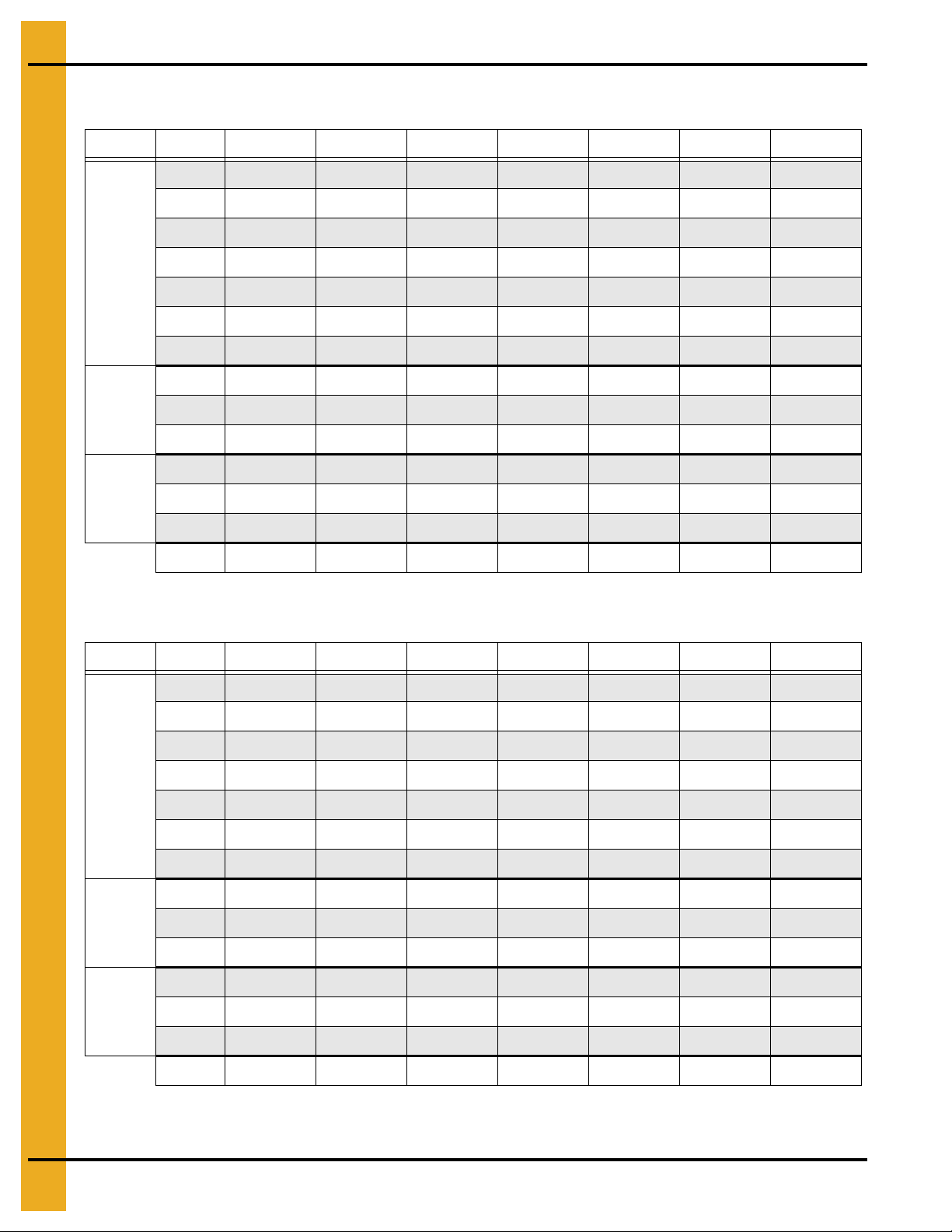
12. Inverted “T” Foundation 2.66" Outside Stiffened Commercial Tanks
Diameter of Bin: 36'
Soil Bearing Capacity: 3000 PSF
Ring #12141618202224
A 1'-0" 1'-0" 1'-0" 1'-0" 1'-0" 1'-0" 1'-0"
B 2'-3" 2'-11" 3'-7" 4'-4" 5'-1" 5'-10" 6'-4"
C 18'-10" 18'-10" 18'-10" 18'-10" 18'-10" 18'-10" 18'-10"
D 19'-3" 19'-7" 19'-10" 20'-2" 20'-6" 20'-11" 21'-1"
M 5 #4's 5 #4's 5 #4's 5 #4's 5 #4's 5 #4's 5 #4's
N 3 #5's 3 #5's 4 #5's 5 #5's 5 #5's 6 #5's 6 #5's
P #5 @ 14" c/c #5 @ 14" c/c #5 @ 14" c/c #5 @ 14" c/c #5 @ 14" c/c #5 @ 11" c/c #6 @ 12" c/c
#4 (ft.) 3800 3800 3800 3800 3800 3800 3800
Rerod
Cu. Yds.
Concrete
Diameter of Bin: 42'
Soil Bearing Capacity: 3000 PSF
#5 (ft.) 600 700 800 1000 1100 1400 700
#6 (ft.)000000700
Footing 10 13 16 19 22 25 27
Wall 21 21 21 21 21 21 21
Floor 18 18 18 18 18 18 18
Total49525558616466
Ring #12141618202224
A 1'-0" 1'-0" 1'-0" 1'-0" 1'-0" 1'-0" 1'-0"
B 2'-5" 3'-1" 3'-9" 4'-6" 5'-5" 6'-0" 6'-11"
C 21'-10" 21'-10" 21'-10" 21'-10" 21'-10" 21'-10" 21'-10"
D 22'-4" 22'-8" 22'-11" 23'-3" 23'-8" 23'-11" 24'-4"
M 5 #4's 5 #4's 5 #4's 5 #4's 6 #4's 6 #4's 6 #4's
N 3 #5's 3 #5's 4 #5's 5 #5's 6 #5's 6 #5's 7 #5's
P #5 @ 14" c/c #5 @ 14" c/c #5 @ 14" c/c #5 @ 14" c/c #5 @ 13" c/c #6 @ 14" c/c #6 @ 10" c/c
#4 (ft.) 4700 4700 4700 4700 4900 4900 4900
Rerod
Cu. Yds.
Concrete
#5 (ft.) 700 700 1000 1200 1400 800 1000
#6 (ft.)000007001100
Footing 12 16 19 22 27 30 34
Wall 24 24 24 24 24 24 24
Floor 25 25 35 25 25 25 25
Total61656871767983
60 PNEG-318 Concrete Foundation Recommendations for GSI Grain Bins
Page 61

12. Inverted “T” Foundation 2.66" Outside Stiffened Commercial Tanks
Diameter of Bin: 48'
Soil Bearing Capacity: 3000 PSF
Ring #12141618202224
A 1'-0" 1'-0" 1'-0" 1'-0" 1'-0" 1'-0" 1'-0"
B 2'-7" 3'-3" 4'-0" 4'-10" 5'-7" 6'-4" 7'-3"
C 24'-10" 24'-10" 24'-10" 24'-10" 24'-10" 24'-10" 24'-10"
D 25'-5" 25'-9" 26'-1" 26'-5" 26'-9" 27'-1" 27'-6"
M 5 #4's 6 #4's 6 #4's 7 #4's 5 #5's 5 #5's 5 #5's
N 3 #5's 4 #5's 4 #5's 5 #5's 6 #5's 6 #5's 7 #5's
P #5 @ 14" c/c #5 @ 14" c/c #5 @ 14" c/c #5 @ 14" c/c #5 @ 12" c/c #6 @ 12" c/c #6 @ 8" c/c
#4 (ft.) 5700 6000 6000 6 300 4100 4100 4100
Rerod
Cu. Yds.
Concrete
Diameter of Bin: 54'
Soil Bearing Capacity: 3000 PSF
#5 (ft.) 800 1100 1200 1400 3400 2600 2700
#6 (ft.)000009001600
Footing 15 19 23 27 32 36 41
Wall 28 28 28 28 28 28 28
Floor 33 33 33 33 33 33 33
Total768080849397102
Ring #12141618202224
A 1'-0" 1'-0" 1'-0" 1'-0" 1'-0" 1'-0" 1'-1"
B 2'-9" 3'-5" 4'-3" 5'-1" 6'-0" 6'-9" 7'-8"
C 27'-10" 27'-10" 27'-10" 27'-10" 27'-10" 27'-10" 27'-10"
D 28'-2" 28'-6" 28'-10" 29'-2" 29'-6" 29'-10" 30'-2"
M 5 #4's 6 #4's 6 #4's 7 #4's 7 #4's 5 #5's 5 #5's
N 3 #5's 4 #5's 4 #5's 5 #5's 6 #5's 6 #5's 7 #5's
P #5 @ 14" c/c #5 @ 14" c/c #5 @ 14" c/c #5 @ 14" c/c #5 @ 13" c/c #6 @ 13" c/c #6 @ 9" c/c
#4 (ft.) 6500 6900 6900 7 200 7200 4800 4800
Rerod
Cu. Yds.
Concrete
#5 (ft.) 900 1200 1300 1600 2000 2800 3100
#6 (ft.)0000011001700
Footing 18 23 28 33 38 43 52
Wall 33 33 33 33 33 33 33
Floor 42 42 42 42 42 42 42
Total 93 98 103 108 113 118 127
PNEG-318 Concrete Foundation Recommendations for GSI Grain Bins 61
Page 62

12. Inverted “T” Foundation 2.66" Outside Stiffened Commercial Tanks
Diameter of Bin: 60'
Soil Bearing Capacity: 3000 PSF
Ring #12141618202224
A 1'-0" 1'-0" 1'-0" 1'-0" 1'-0" 1'-0" 1'-1"
B 2'-10" 3'-6" 4'-5" 5'-3" 6'-2" 7'-1" 8'-0"
C 30'-9" 30'-9" 30'-9" 30'-9" 30'-9" 30'-9" 30'-9"
D 31'-6" 31'-9" 32'-2" 32'-6" 32'-11" 33'-4" 33'-9"
M 5 #4's 6 #4's 7 #4's 7 #4's 5 #5's 5 #5's 6 #5's
N 3 #5's 4 #5's 5 #5's 5 #5's 6 #5's 7 #5's 8 #5's
P #5 @ 14" c/c #5 @ 14" c/c #5 @ 14" c/c #5 @ 14" c/c #5 @ 14" c/c #6 @ 14" c/c #6 @ 11" c/c
#4 (ft.) 7700 8100 8500 8500 5800 5800 5900
Rerod
Cu. Yds.
Concrete
Diameter of Bin: 72'
Soil Bearing Capacity: 3000 PSF
#5 (ft.) 1000 1300 1700 1800 4100 3300 3800
#6 (ft.)0000011001600
Footing 20 25 31 37 43 50 61
Wall 35 35 35 35 35 35 35
Floor 52 51 51 51 51 51 51
Total 106 111 117 123 129 136 147
Ring #12141618202224
A 1'-0" 1'-0" 1'-0" 1'-0" 1'-0" 1'-0" 1'-1"
B 3'-0" 3'-10" 4'-8" 5'-9" 6'-9" 7'-8" 8'-7"
C 36'-9" 36'-9" 36'-9" 36'-9" 36'-9" 36'-9" 36'-9"
D 37'-6" 37'-11" 38'-3" 38'-9" 39'-7" 40'-0" 40'-0"
M 6 #4's 7 #4's 5 #5's 5 #5's 5 #5's 6 #5's 6 #5's
N 3 #5's 4 #5's 5 #5's 6 #5's 7 #5's 8 #5's 9 #5's
P #5 @ 14" c/c #5 @ 14" c/c #5 @ 14" c/c #5 @ 14" c/c #5 @ 12" c/c #6 @ 12" c/c #6 @ 10" c/c
#4 (ft.) 10600 11000 7800 7800 7800 7800 7900
Rerod
Cu. Yds.
Concrete
#5 (ft.) 1200 1700 4400 4800 5400 4700 4900
#6 (ft.)0000017002200
Footing 26 33 40 49 57 65 78
Wall 42 42 42 42 42 42 42
Floor 74 74 74 74 74 74 74
Total 142 149 156 165 173 181 194
62 PNEG-318 Concrete Foundation Recommendations for GSI Grain Bins
Page 63

12. Inverted “T” Foundation 2.66" Outside Stiffened Commercial Tanks
Diameter of Bin: 75'
Soil Bearing Capacity: 3000 PSF
Ring #12141618202224
A 1'-0" 1'-0" 1'-0" 1'-0" 1'-0" 1'-0" 1'-2"
B 3'-1" 3'-11" 4'-10" 5'-10" 6'-9" 7'-8" 8'-9"
C 38'-3" 38'-3" 38'-3" 38'-3" 38'-3" 38'-3" 38'-3"
D 39'-1" 39'-5" 39'-10" 40'-3" 40'-8" 41'-1" 41'-7"
M 6 #4's 7 #4's 5 #5's 5 #5's 6 #5's 6 #5's 6 #5's
N 3 #5's 4 #5's 5 #5's 6 #5's 7 #5's 8 #5's 10 #5's
P #5 @ 14" c/c #5 @ 14" c/c #5 @ 14" c/c #5 @ 14" c/c #5 @ 11" c/c #6 @ 11" c/c #6 @ 10" c/c
#4 (ft.) 11300 11800 8400 8400 8400 8400 8500
Rerod
Cu. Yds.
Concrete
Diameter of Bin: 78'
Soil Bearing Capacity: 3000 PSF
#5 (ft.) 1400 1700 4500 5000 6200 4800 5300
#6 (ft.)0000019002400
Footing 27 35 43 51 59 67 89
Wall 43 43 43 43 43 43 43
Floor 80 80 80 80 80 80 80
Total 150 158 166 174 182 190 212
Ring #12141618202224
A 1'-0" 1'-0" 1'-0" 1'-0" 1'-0" 1'-0" 1'-2"
B 3'-2" 4'-0" 4'-10" 5'-10" 6'-11" 7'-10" 8'-11"
C 39'-9" 39'-9" 39'-9" 39'-9" 39'-9" 39'-9" 39'-9"
D 40'-7" 41'-0" 41'-4" 41'-9" 42'-3" 42'-8" 43'-1"
M 7 #4's 5 #5's 5 #5's 5 #5's 6 #5's 6 #5's 7 #5's
N 3 #5's 4 #5's 5 #5's 6 #5's 7 #5's 8 #5's 10 #5's
P #5 @ 14" c/c #5 @ 14" c/c #5 @ 14" c/c #5 @ 14" c/c #5 @ 11" c/c #6 @ 11" c/c #6 @ 9" c/c
#4 (ft.) 12500 9000 9000 9000 9000 9000 9100
Rerod
Cu. Yds.
Concrete
#5 (ft.) 1400 4300 4800 5200 6600 5000 6000
#6 (ft.)0000020002800
Footing 29 37 44 53 63 71 94
Wall 45 45 45 45 45 45 45
Floor 87 87 87 87 87 87 87
Total 161 169 176 185 195 203 226
PNEG-318 Concrete Foundation Recommendations for GSI Grain Bins 63
Page 64

12. Inverted “T” Foundation 2.66" Outside Stiffened Commercial Tanks
Diameter of Bin: 90'
Soil Bearing Capacity: 3000 PSF
Ring #12141618202224 *
A 1'-0" 1'-0" 1'-0" 1'-0" 1'-0" 1'-1" 1'-2"
B 3'-5" 4'-4" 5'-3" 6'-2" 7'-3" 8'-5" 9'-6"
C 45'-9" 45'-9" 45'-9" 45'-9" 45'-9" 45'-9" 45'-10"
D 46'-8" 47'-1" 47'-6" 47'-11" 48'-5" 48'-11" 49'-6"
M 5 #5's 6 #5's 6 #5's 7 #5's 5 #6's 5 #6's 6 #6's
N 4 #5's 5 #5's 5 #5's 6 #5's 7 #5's 9 #5's 11 #5's
P #5 @ 14" c/c #5 @ 14" c/c #5 @ 14" c/c #5 @ 14" c/c #6 @ 13" c/c #6 @ 10" c/c #6 @ 8" c/c
#4 (ft.) 11400 11400 11400 11400 11400 11500 11500
Rerod
Cu. Yds.
Concrete
* 1'-6" Wall Width
Diameter of Bin: 105'
Soil Bearing Capacity: 3000 PSF
#5 (ft.) 4900 6000 6200 7100 2000 2600 3100
#6 (ft.)0000470056007200
Footing 36 46 55 65 76 95 116
Wall 52 52 52 52 52 52 62
Floor 116 113 116 116 116 116 116
Total 204 214 223 233 244 263 294
Ring #12141618202223 *
A 1'-0" 1'-0" 1'-0" 1'-0" 1'-0" 1'-2" 1'-2"
B 3'-9" 4'-8" 5'-9" 6'-9" 7'-10" 8'-11" 9'-7"
C 53'-2" 53'-2" 53'-2" 53'-2" 53'-2" 53'-2" 53'-2"
D 54'-3" 54'-8" 55'-2" 55'-7" 56'-1" 56'-7" 57'-1"
M 6 #5's 5 #6's 5 #6's 6 #6's 6 #6's 7 #6's 7 #6's
N 4 #5's 5 #5's 6 #5's 7 #5's 8 #5's 10 #5's 11 #5's
P #5 @ 14" c/c #5 @ 14" c/c #5 @ 14" c/c #5 @ 12" c/c #5 @ 11" c/c #6 @ 9" c/c #6 @ 8" c/c
#4 (ft.) 14900 14900 14900 14900 14900 15000 14900
Rerod
Cu. Yds.
Concrete
* 1'-6" Wall Width
#5 (ft.) 6400 2900 3500 4400 5400 3300 3700
#6 (ft.) 0 3400 2900 4000 4000 8400 9200
Footing 46 57 70 83 96 127 137
Wall 61 61 61 61 61 61 73
Floor 157 157 157 157 157 157 157
Total 264 275 288 301 314 345 367
64 PNEG-318 Concrete Foundation Recommendations for GSI Grain Bins
Page 65

12. Inverted “T” Foundation 2.66" Outside Stiffened Commercial Tanks
All foundation specifications shall be construed as
recommendations only. Because of the many
variable conditions in actual installation, GSI
assumes no liability for results arising from the use
of such recommendations.
3500 PSF Soil Bearing Capacity
Inverted “T” Foundation Notes:
1. The foundation design is based on a minimum allowable soil bearing capacity of 3500 PSF. Bearing
capacity of the soils should be determined by geotechnical investigation and be of uniform
bearing capacity.
2. The foundation site must be free of vegetation and debris and well drained.
3. The foundation must be founded below the frost line or constructed on non-expansive frost free fill.
4. All material used for backfill inside the ring wall should be clean, well graded, crushed rock or a
sand-gravel mixture. Backfill should be placed in 6" lifts, 95% compaction.
5. All reinforcement must meet the requirements of ASTM A615 grade 60 deformed bars.
6. Lap all circumferential bars 35 bar diameters and stagger all laps in plans 3'-0". Estimates do not
include end laps.
7. Concrete must have a minimum compressive strength of 3000 PSI at 28 days, 6%-8% air
entrainment, 4" slump.
PNEG-318 Concrete Foundation Recommendations for GSI Grain Bins 65
Figure 12B
Page 66

12. Inverted “T” Foundation 2.66" Outside Stiffened Commercial Tanks
Diameter of Bin: 18'
Soil Bearing Capacity: 3500 PSF
Ring #12141618
A 1'-0" 1'-0" 1'-0" 1'-0"
B 1'-6" 1'-10" 2'-3" 2'-8"
C 9'-10" 9'-10" 9'-10" 9'-10"
D 9'-11" 10'-1" 10'-3" 10'-5"
M 5 #4's 5 #4's 5 #4's 5 #4's
N 2 #5 's 3 #5's 3 #5's 3 #5's
P #5 @ 14" c/c #5 @ 14" c/c #5 @ 14" c/c #5 @ 14" c/c
#4 (ft.) 1700 1700 1700 1700
Rerod
Cu. Yds.
Concrete
Diameter of Bin: 21'
Soil Bearing Capacity: 3500 PSF
#5 (ft.) 300 300 300 400
#6 (ft.) 0 0 0 0
Footing 4 4 5 6
Wall 10 10 10 10
Floor 5 5 5 5
Total19192021
Ring #12141618
A 1'-0" 1'-0" 1'-0" 1'-0"
B 1'-7" 2'-0" 2'-5" 2'-10"
C 11'-4" 11'-4" 11'-4" 11'-4"
D 11'-6" 11'-8" 11'-10" 12'-0"
M 5 #4's 5 #4's 5 #4's 5 #4's
N 2 #5 's 2 #5's 3 #5's 3 #5's
P #5 @ 14" c/c #5 @ 14" c/c #5 @ 14" c/c #5 @ 14" c/c
#4 (ft.) 2100 2100 2100 2100
Rerod
Cu. Yds.
Concrete
#5 (ft.) 300 300 500 400
#6 (ft.) 0 0 0 0
Footing 4 5 6 7
Wall 12 12 12 12
Floor 6 6 6 6
Total22232425
66 PNEG-318 Concrete Foundation Recommendations for GSI Grain Bins
Page 67

12. Inverted “T” Foundation 2.66" Outside Stiffened Commercial Tanks
Diameter of Bin: 24'
Soil Bearing Capacity: 3500 PSF
Ring #12141618202224
A 1'-0" 1'-0" 1'-0" 1'-0" 1'-0" 1'-0" 1'-0"
B 1'-9" 2'-1" 2'-6" 3'-0" 3'-6" 4'-1" 4'-8"
C 12'-10" 12'-10" 12'-10" 12'-10" 12'-10" 12'-10" 12'-10"
D 13'-0" 13'-2" 13'-4" 13'-7" 13'-10" 14'-1" 14'-4"
M 5 #4's 5 #4's 5 #4's 5 #4's 5 #4's 5 #4's 5 #4's
N 2 #5's 2 #5's 3 #5's 3 #5's 4 #5's 4 #5's 5 #5's
P #5 @ 14" c/c #5 @ 14" c/c #5 @ 14" c/c #5 @ 14" c/c #5 @ 14" c/c #5 @ 14" c/c #5 @ 14" c/c
#4 (ft.) 2300 2300 2300 2 300 2300 2300 2300
Rerod
Cu. Yds.
Concrete
Diameter of Bin: 27'
Soil Bearing Capacity: 3500 PSF
#5 (ft.) 300 400 500 500 600 700 700
#6 (ft.)0000000
Footing 5 6 8 9 10 12 14
Wall 14 14 14 14 14 14 14
Floor 8 8 8 8 8 8 8
Total27283031323436
Ring #12141618202224
A 1'-0" 1'-0" 1'-0" 1'-0" 1'-0" 1'-0" 1'-0"
B 1'-9" 2'-2" 2'-8" 3'-2" 3'-9" 4'-4" 4'-10"
C 14'-4" 14'-4" 14'-4" 14'-4" 14'-4" 14'-4" 14'-4"
D 14'-7" 14'-9" 15'-0" 15'-2" 15'-5" 15'-8" 15'-11"
M 5 #4's 5 #4's 5 #4's 5 #4's 5 #4's 5 #4's 5 #4's
N 2 #5's 3 #5's 3 #5's 3 #5's 4 #5's 5 #5's 5 #5's
P #5 @ 14" c/c #5 @ 14" c/c #5 @ 14" c/c #5 @ 14" c/c #5 @ 14" c/c #5 @ 14" c/c #5 @ 14" c/c
#4 (ft.) 2800 2800 2800 2 800 2800 2800 2800
Rerod
Cu. Yds.
Concrete
#5 (ft.) 300 500 500 500 700 800 900
#6 (ft.)0000000
Footing 6 7 9 11 12 14 16
Wall 15 15 15 15 15 15 15
Floor 10 10 10 10 10 10 10
Total31323436373941
PNEG-318 Concrete Foundation Recommendations for GSI Grain Bins 67
Page 68
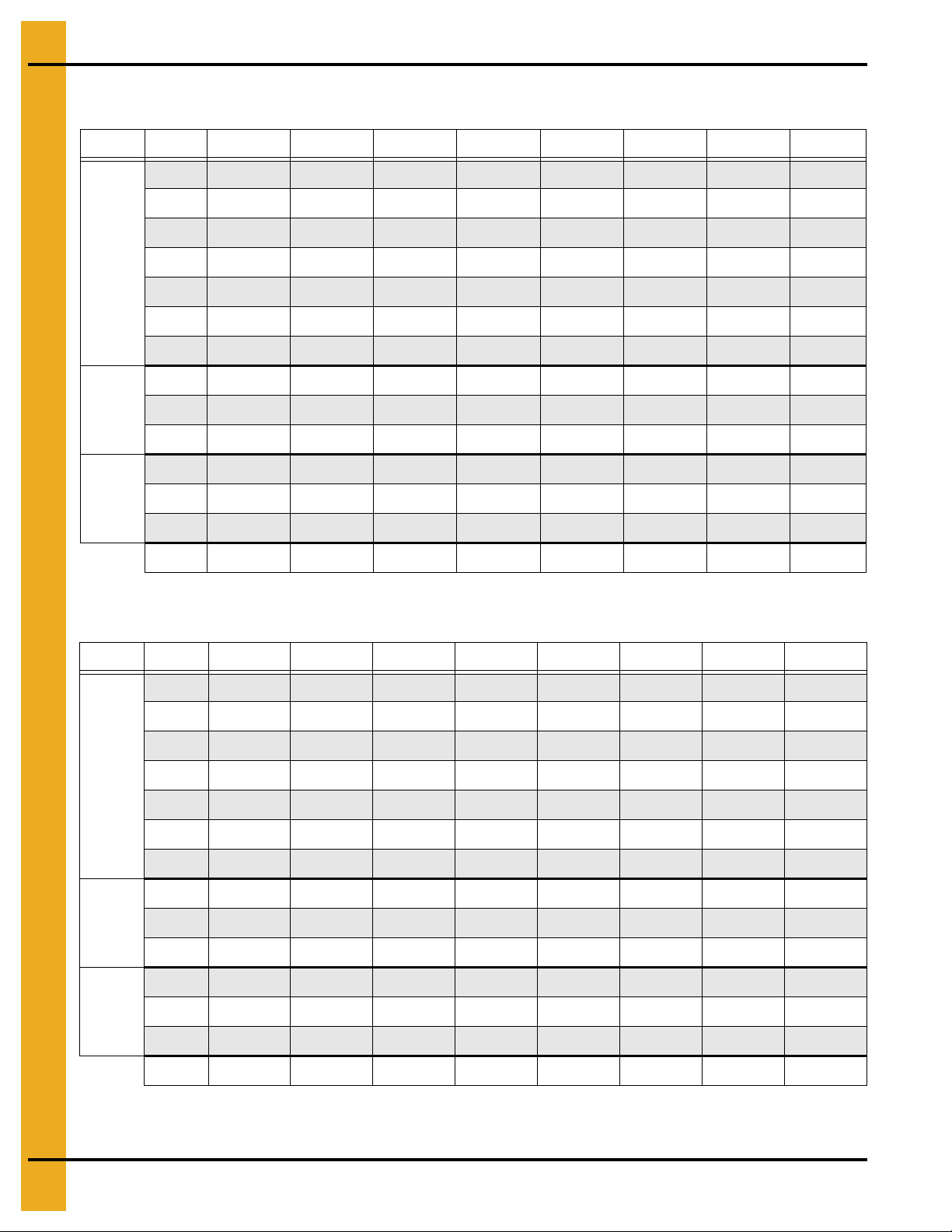
12. Inverted “T” Foundation 2.66" Outside Stiffened Commercial Tanks
Diameter of Bin: 30'
Soil Bearing Capacity: 3500 PSF
Ring #1214161820222427
A 1'-0" 1'-0" 1'-0" 1'-0" 1'-0" 1'-0" 1'-0" 1'-0"
B 1'-9" 2'-3" 2'-9" 3'-4" 3'-11" 4'-6" 5'-1" 6'-6"
C 15'-10" 15'-10" 15'-10" 15'-10" 15'-10" 15'-10" 15'-10" 15'-10"
D 16'-0" 16'-3" 16'-6" 16'-9" 17'-0" 17'-3" 18'-3" 19'-1"
M 5 #4's 5 #4's 5 #4's 5 #4's 5 #4's 5 #4's 5 #4's 5 #4's
N 2 #5's 3 #5's 3 #5's 4 #5's 4 #5's 5 #5 's 5 #5's 6 #5's
P #5 @ 14" c/c #5 @ 14" c/c #5 @ 14" c/c #5 @ 14" c/c #5 @ 14" c/c #5 @ 14" c/c #5 @ 13" c/c #6 @ 9" c/c
#4 (ft.) 3000 3000 3000 3000 3000 30 00 3000 3000
Rerod
Cu. Yds.
Concrete
Diameter of Bin: 33'
Soil Bearing Capacity: 3500 PSF
#5 (ft.) 400 500 500 700 700 900 1000 600
#6 (ft.)0000000800
Footing 7 8 10 12 14 16 19 24
Wall 17 17 17 17 17 17 17 17
Floor 13 13 13 13 13 13 13 13
Total3738404244464954
Ring #1214161820222427
A 1'-0" 1'-0" 1'-0" 1'-0" 1'-0" 1'-0" 1'-0" 1'-0"
B 1'-10" 2'-4" 2'-10" 3'-5" 4'-1" 4'-8" 5'-3" 7'-3"
C 17'-4" 17'-4" 17'-4" 17'-4" 17'-4" 17'-4" 17'-4" 17'-4"
D 17'-7" 17'-10" 18'-0" 18'-3" 18'-7" 18'-10" 19'-1" 20'-0"
M 5 #4's 5 #4's 5 #4's 5 #4's 5 #4's 5 #4's 5 #4's 5 #4's
N 2 #5's 3 #5's 3 #5's 4 #5's 4 #5's 5 #5's 5 #5's 6 #5's
P #5 @ 14" c/c#5 @ 14" c/c #5 @ 14" c/c #5 @ 14" c/c #5 @ 14" c/c#5 @ 14" c/c#5 @ 12" c/c#6 @ 12" c/c
#4 (ft.) 3400 3400 3400 3400 3400 3400 3400 3400
Rerod
Cu. Yds.
Concrete
#5 (ft.) 500 600 700 800 900 1000 1100 700
#6 (ft.)0000000700
Footing 8 10 11 14 16 18 21 28
Wall 19 19 19 19 19 19 19 19
Floor 16 16 16 16 16 16 16 16
Total4345464951535663
68 PNEG-318 Concrete Foundation Recommendations for GSI Grain Bins
Page 69
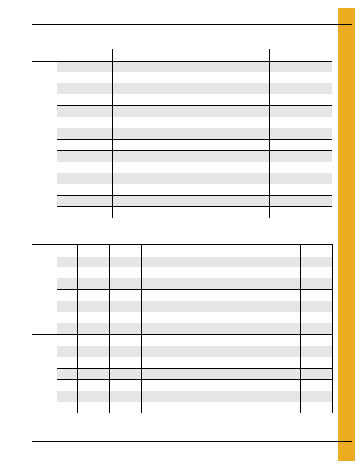
12. Inverted “T” Foundation 2.66" Outside Stiffened Commercial Tanks
Diameter of Bin: 36'
Soil Bearing Capacity: 3500 PSF
Ring #1214161820222427
A 1'-0" 1'-0" 1'-0" 1'-0" 1'-0" 1'-0" 1'-0" 1'-0"
B 1'-11" 2'-5" 2'-11" 3'-7" 4'-3" 4'-10" 5'-5" 7'-0"
C 18'-10" 18'-10" 18'-10" 18'-10" 18'-10" 18'-10" 18'-10" 18'-10"
D 19'-2" 19'-4" 19'-7" 19'-10" 20'-2" 20'-5" 20'-8" 21'-4"
M 5 #4's 5 #4's 5 #4's 5 #4's 5 #4's 5 #4's 5 #4's 5 #4's
N 2 #5's 3 #5's 3 #5's 4 #5's 4 #5's 5 #5's 6 #5's 6 #5's
P #5 @ 14" c/c #5 @ 14" c/c #5 @ 14" c/c #5 @ 14" c/c #5 @ 14" c/c #5 @ 14" c/c #5 @ 11" c/c#6 @ 12" c/c
#4 (ft.) 3800 3800 3800 3800 3800 3800 3800 3400
Rerod
Cu. Yds.
Concrete
Diameter of Bin: 42'
Soil Bearing Capacity: 3500 PSF
#5 (ft.) 500 600 700 800 900 1100 1400 700
#6 (ft.)0000000800
Footing 9 11 13 16 18 21 23 30
Wall 21 21 21 21 21 21 21 21
Floor 18 18 18 18 18 18 18 18
Total4850525557606269
Ring #1214161820222427
A 1'-0" 1'-0" 1'-0" 1'-0" 1'-0" 1'-0" 1'-0" 1'-1"
B 2'-0" 2'-6" 3'-2" 3'-9" 4'-6" 5'-3" 6'-0" 7'-6"
C 21'-10" 21'-10" 21'-10" 21'-10" 21'-10" 21'-10" 21'-10" 21'-10"
D 22'-2" 22'-4" 22'-8" 22'-11" 23'-3" 23'-7" 23'-11" 24'-7"
M 5 #4's 5 #4's 5 #4's 5 #4's 6 #4's 6 #4's 6 #4's 6 #4's
N 2 #5's 3 #5's 3 #5's 4 #5's 5 #5's 5 #5's 6 #5's 7 #5's
P #5 @ 14" c/c #5 @ 14" c/c #5 @ 14" c/c #5 @ 14" c/c #5 @ 14" c/c #5 @ 12" c/c #6 @ 12" c/c #6 @ 10" c/c
#4 (ft.) 4700 4700 4700 4700 4900 4900 4900 5000
Rerod
Cu. Yds.
Concrete
#5 (ft.) 500 700 800 1000 1200 1400 800 1000
#6 (ft.)0000008001100
Footing 10 13 16 19 22 26 30 40
Wall 24 24 24 24 24 24 24 24
Floor 25 25 25 25 25 25 25 25
Total5962656871757989
PNEG-318 Concrete Foundation Recommendations for GSI Grain Bins 69
Page 70

12. Inverted “T” Foundation 2.66" Outside Stiffened Commercial Tanks
Diameter of Bin: 48'
Soil Bearing Capacity: 3500 PSF
Ring #1214161820222427
A 1'-0" 1'-0" 1'-0" 1'-0" 1'-0" 1'-0" 1'-0" 1'-3"
B 2'-1" 2'-8" 3'-4" 4'-0" 4'-8" 5'-5" 6'-2" 8'-0"
C 24'-10" 24'-10" 24'-10" 24'-10" 24'-10" 24'-10" 24'-10" 24'-10"
D 25'-2" 25'-6" 25'-9" 26'-1" 26'-4" 26'-8" 27'-0" 27'-6"
M 5 #4's 6 #4's 6 #4's 7 #4's 5 #5's 5 #5's 5 #5's 6 #5's
N 2 #5's 3 #5's 4 #5 's 4 #5's 5 #5's 6 #5's 6 #5's 10 #5's
P #5 @ 14" c/c#5 @ 14" c/c #5 @ 14" c/c #5 @ 14" c/c #5 @ 14" c/c #5 @ 11" c/c #6 @ 11" c/c #6 @ 11" c/c
#4 (ft.) 5700 6000 6000 6300 4100 4100 4100 4200
Rerod
Cu. Yds.
Concrete
Diameter of Bin: 54'
Soil Bearing Capacity: 3500 PSF
#5 (ft.) 700 800 1100 1200 3000 3500 2600 3400
#6 (ft.) 0 0 0 0 0 0 1000 1300
Footing 12 15 19 23 27 31 35 55
Wall 28 28 28 28 28 28 28 28
Floor 33 33 33 33 33 33 33 33
Total73768084889296116
Ring #1214161820222427
A 1'-0" 1'-0" 1'-0" 1'-0" 1'-0" 1'-0" 1'-0" 1'-2"
B 2'-3" 2'-10" 3'-6" 4'-3" 5'-1" 5'-9" 6'-6" 8'-9"
C 27'-10" 27'-10" 27'-10" 27'-10" 27'-10" 27'-10" 27'-10" 27'-10"
D 28'-2" 28'-6" 28'-10" 29'-2" 29'-6" 29'-10" 30'-2" 30'-6"
M 5 #4's 6 #4's 6 #4's 7 #4's 7 #4' s 5 #5's 5 #5's 6 #5's
N 2 #5's 3 #5's 4 #5's 5 #5's 5 #5's 6 #5's 7 #5's 10 #5's
P #5 @ 14" c/c #5 @ 14" c/c #5 @ 14" c/c #5 @ 14" c/c #5 @ 14" c/c #5 @ 12" c/c #6 @ 11" c/c #6 @ 10" c/c
#4 (ft.) 6500 6900 6900 7200 7200 4800 4800 4900
Rerod
Cu. Yds.
Concrete
#5 (ft.) 700 900 1200 1500 1600 3700 3000 3400
#6 (ft.)00000012001700
Footing 15 19 23 28 33 37 42 63
Wall 33 33 33 33 33 33 33 33
Floor 42 42 42 42 42 42 42 42
Total 90 94 98 103 108 112 1 17 138
70 PNEG-318 Concrete Foundation Recommendations for GSI Grain Bins
Page 71

12. Inverted “T” Foundation 2.66" Outside Stiffened Commercial Tanks
Diameter of Bin: 60'
Soil Bearing Capacity: 3500 PSF
Ring #1214161820222427
A 1'-0" 1'-0" 1'-0" 1'-0" 1'-0" 1'-0" 1'-0" 1'-2"
B 2'-4" 2'-11" 3'-7" 4'-5" 5'-3" 6'-0" 6'-11" 9'-3"
C 30'-9" 30'-9" 30'-9" 30'-9" 30'-9" 30'-9" 30'-9" 30'-9"
D 31'-3" 31'-6" 31'-9" 32'-2" 32'-6" 32'-10" 33'-3" 34'-4"
M 5 #4's 5 #4's 6 #4's 6 #4's 6 #4's 7 #4's 5 #5's 6 #5's
N 3 #5's 3 #5's 4 #5's 5 #5's 5 #5's 6 #5's 7 #5's 10 #5's
P #5 @ 14" c/c #5 @ 14" c/c #5 @ 14" c/c #5 @ 14" c/c #5 @ 14" c/c #5 @ 13" c/c #6 @ 11" c/c #6 @ 8" c/c
#4 (ft.) 7700 7700 8100 8100 8100 8500 5800 5900
Rerod
Cu. Yds.
Concrete
Diameter of Bin: 72'
Soil Bearing Capacity: 3500 PSF
#5 (ft.) 900 1000 1300 1700 1800 2200 3300 4200
#6 (ft.) 0 0 0 0 0 0 1400 2500
Footing 17 21 25 31 37 42 48 75
Wall 35 35 35 35 35 35 35 35
Floor 51 51 51 51 51 51 51 51
Total 103 107 111 117 123 128 134 161
Ring #1214161820222427
A 1'-0" 1'-0" 1'-0" 1'-0" 1'-0" 1'-0" 1'-1" 1'-3"
B 2'-6" 3'-2" 3'-11" 4'-9" 5'-7" 6'-6" 7'-6" 9'-2"
C 36'-9" 36'-9" 36'-9" 36'-9" 36'-9" 36'-9" 36'-9" 36'-9"
D 37'-4" 37'-7" 37'-11" 38'-4" 38'-8" 39'-1" 40'-4" 40'-6"
M 6 #4's 7 #4's 5 #5's 5 #5's 5 #5's 6 #5's 6 #5's 6 #5's
N 3 #5's 3 #5's 4 #5's 5 #5's 6 #5's 7 #5's 8 #5's 12 #5's
P #5 @ 14" c/c #5 @ 14" c/c #5 @ 14" c/c #5 @ 14" c/c #5 @ 14" c/c #5 @ 10" c/c #6 @ 11" c/c #6 @ 8" c/c
#4 (ft.) 10600 11000 7800 7800 7800 7800 7900 7900
Rerod
Cu. Yds.
Concrete
#5 (ft.) 1100 1300 4000 4400 4700 6100 4700 5600
#6 (ft.) 0 0 0 0 0 0 1800 3000
Footing 21 27 33 40 47 55 70 96
Wall 42 42 42 42 42 42 42 42
Floor 74 74 74 74 74 74 74 74
Total 137 143 149 156 163 171 186 212
PNEG-318 Concrete Foundation Recommendations for GSI Grain Bins 71
Page 72

12. Inverted “T” Foundation 2.66" Outside Stiffened Commercial Tanks
Diameter of Bin: 75'
Soil Bearing Capacity: 3500 PSF
Ring #1214161820222427
A 1'-0" 1'-0" 1'-0" 1'-0" 1'-0" 1'-0" 1'-2" 1'-3"
B 2'-7" 3'-3" 4'-0" 4'-10" 5'-9" 6'-6" 7'-8" 10'-5"
C 38'-3" 38'-3" 38'-3" 38'-3" 38'-3" 38'-3" 38'-3" 38'-3"
D 38'-10" 39'-2" 39'-6" 39'-10" 40'-3" 40'-7" 41'-1" 42'-8"
M 6 #4's 7 #4's 5 #5's 5 #5's 6 #5's 6 #5's 6 #5's 6 #5's
N 3 #5's 4 #5's 4 #5's 5 #5's 6 #5's 6 #5's 8 #5's 13 #5's
P #5 @ 14" c/c#5 @ 14" c/c #5 @ 14" c/c #5 @ 14" c/c #5 @ 14" c/c#5 @ 10" c/c#6 @ 10" c/c #6 @ 9" c/c
#4 (ft.) 11300 11800 8400 8400 8400 8400 8500 8500
Rerod
Cu. Yds.
Concrete
Diameter of Bin: 78'
Soil Bearing Capacity: 3500 PSF
#5 (ft.) 1300 1600 4200 4500 5500 6100 4800 6000
#6 (ft.) 0 0 0 0 0 0 2100 3200
Footing 23 29 35 43 51 57 72 114
Wall 43 43 43 43 43 43 43 43
Floor 80 80 80 80 80 80 80 80
Total 146 152 158 166 174 180 195 237
Ring #1214161820222427
A 1'-0" 1'-0" 1'-0" 1'-0" 1'-0" 1'-0" 1'-1" 1'-3"
B 2'-7" 3'-3" 4'-0" 4'-11" 5'-10" 6'-9" 7'-8" 9'-0"
C 39'-9" 39'-9" 39'-9" 39'-9" 39'-9" 39'-9" 39'-9" 39'-9"
D 40'-4" 40'-8" 41'-0" 41'-5" 41'-9" 42'-2" 42'-7" 43'-4"
M 7 #4's 5 #5's 5 #5's 5 #5's 6 #5's 6 #5's 7 #5's 7 #5's
N 3 #5's 4 #5's 4 #5's 5 #5's 6 #5's 7 #5's 8 #5's 11 #6's
P #5 @ 14" c/c#5 @ 14" c/c #5 @ 14" c/c #5 @ 14" c/c #5 @ 14" c/c#6 @ 14" c/c #6 @ 11 " c/c #6 @ 9" c/c
#4 (ft.) 12500 9000 9000 9000 9000 9000 9100 9100
Rerod
Cu. Yds.
Concrete
#5 (ft.) 1300 4100 4300 4800 5700 4800 5500 3500
#6 (ft.) 0 0 0 0 0 1400 2000 5500
Footing 24 30 37 45 53 61 75 102
Wall 45 45 45 45 45 45 45 45
Floor 87 87 87 87 87 87 87 87
Total 156 162 169 177 185 193 207 234
72 PNEG-318 Concrete Foundation Recommendations for GSI Grain Bins
Page 73

12. Inverted “T” Foundation 2.66" Outside Stiffened Commercial Tanks
Diameter of Bin: 90'
Soil Bearing Capacity: 3500 PSF
Ring #12141618202224 *27 *
A 1'-0" 1'-0" 1'-0" 1'-0" 1'-0" 1'-0" 1'-1" 1'-4"
B 2'-10" 3'-7" 4'-4" 5'-3" 6'-2" 7'-1" 8'-2" 9'-7"
C 45'-9" 45'-9" 45'-9" 45'-9" 45'-9" 45'-9" 45'-10" 45'-10"
D 46'-6" 46'-10" 47'-1" 47'-6" 47'-11" 48'-4" 48'-11" 49'-8"
M 5 #5's 6 #5's 6 #5's 7 #5's 5 #6's 5 #6's 6 #6's 6 #6's
N 3 #5's 4 #5's 5 #5's 5 #5's 6 #5's 7 #5's 9 #5's 12 #6's
P #5 @ 14" c/c #5 @ 14" c/c #5 @ 14" c/c #5 @ 14" c/c #5 @ 12" c/c #6 @ 12" c/c #6 @ 10" c/c #6 @ 8" c/c
#4 (ft.) 11400 11400 11400 11400 11400 11400 11500 11700
Rerod
Cu. Yds.
Concrete
* 1'-6" Wall Width
Diameter of Bin: 105'
Soil Bearing Capacity: 3500 PSF
#5 (ft.) 4400 5500 6000 6700 3300 2000 2600 0
#6 (ft.) 0 0 0 0 2900 4800 6000 10800
Footing 30 38 46 55 65 74 93 134
Wall 52 52 52 52 52 52 62 62
Floor 116 116 116 116 116 116 116 116
Total 198 206 214 223 233 242 271 312
Ring #12141618202223 *27 *
A 1'-0" 1'-0" 1'-0" 1'-0" 1'-0" 1'-1" 1'-1" 1'-9"
B 3'-1" 3'-10" 4'-9" 5'-7" 6'-9" 7'-8" 8'-1" 11'-3"
C 53'-2" 53'-2" 53'-2" 53'-2" 53'-2" 53'-2" 53'-3" 53'-3"
D 54'-0" 54'-4" 54'-9" 55'-1" 55'-7" 56'-0" 56'-3" 57'-8"
M 6 #5's 5 #6's 5 #6's 6 #6's 6 #6's 7 #6's 7 #6's 8 #6's
N 3 #5's 4 #5's 5 #5's 6 #5's 7 #5's 8 #5's 8 #5's 12 #6's
P #5 @ 14" c/c #5 @ 14" c/c #5 @ 14" c/c #5 @ 12" c/c #6 @ 14" c/c #6 @ 10" c/c #6 @ 10" c/c #6 @ 9" c/c
#4 (ft.) 14900 14900 14900 14900 14900 15000 15000 14800
Rerod
Cu. Yds.
Concrete
* 1'-6" Wall Width
#5 (ft.) 5800 2400 2900 3700 2300 2700 2700 0
#6 (ft.) 0 3400 2900 4000 5800 7600 7700 14200
Footing 38 47 58 68 83 101 107 239
Wall 61 61 61 61 61 61 73 73
Floor 157 157 157 157 157 157 158 158
Total 256 265 276 286 301 319 338 470
PNEG-318 Concrete Foundation Recommendations for GSI Grain Bins 73
Page 74
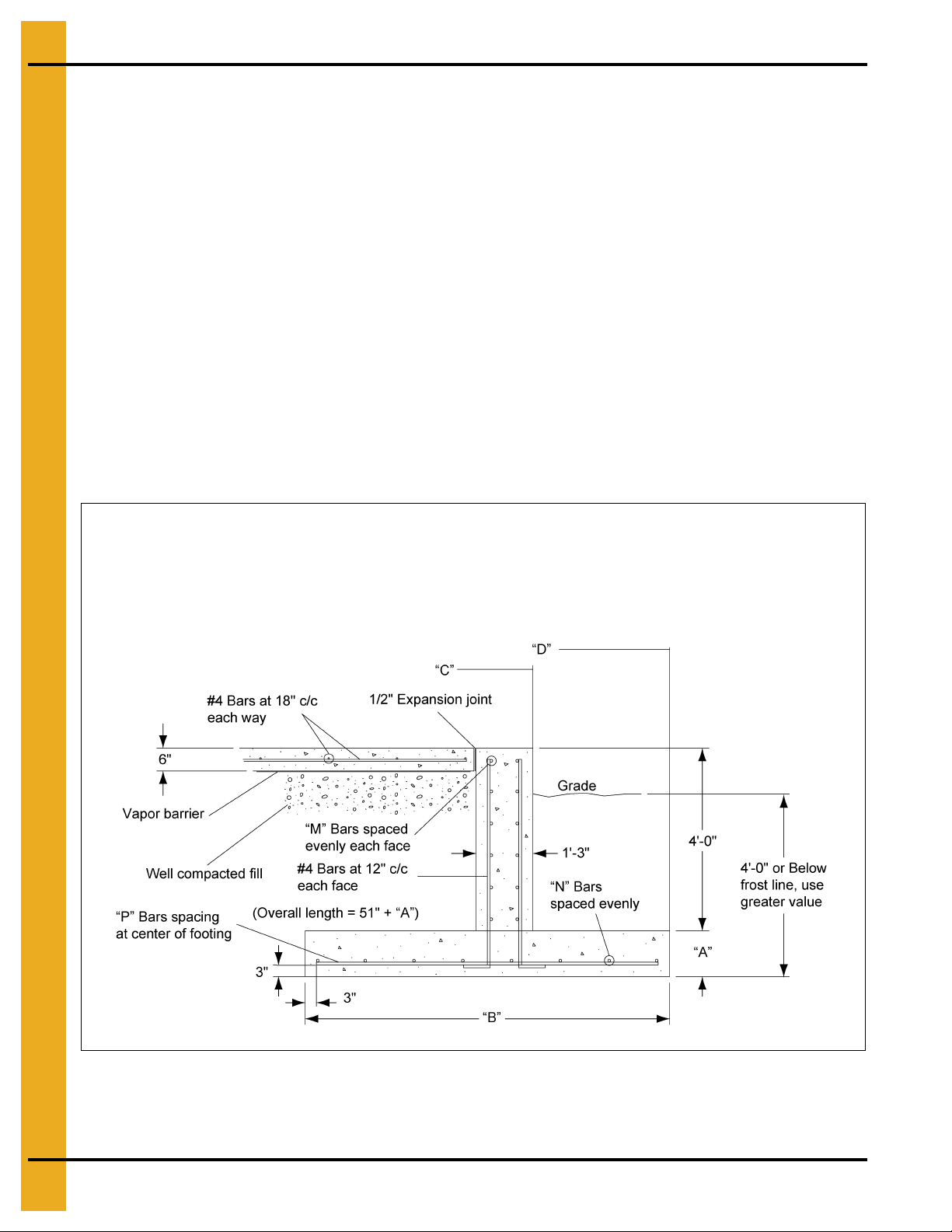
12. Inverted “T” Foundation 2.66" Outside Stiffened Commercial Tanks
All foundation specifications shall be construed as
recommendations only. Because of the many
variable conditions in actual installation, GSI
assumes no liability for results arising from the use
of such recommendations.
4000 PSF Soil Bearing Capacity
Inverted “T” Foundation Notes:
1. The foundation design is based on a minimum allowable soil bearing capacity of 4000 PSF. Bearing
capacity of the soils should be determined by geotechnical investigation and be of uniform
bearing capacity.
2. The foundation site must be free of vegetation and debris and well drained.
3. The foundation must be founded below the frost line or constructed on non-expansive frost free fill.
4. All material used for backfill inside the ring wall should be clean, well graded, crushed rock or a
sand-gravel mixture. Backfill should be placed in 6" lifts, 95% compaction.
5. All reinforcement must meet the requirements of ASTM A615 grade 60 deformed bars.
6. Lap all circumferential bars 35 bar diameters and stagger all laps in plans 3'-0". Estimates do not
include end laps.
7. Concrete must have a minimum compressive strength of 3000 PSI at 28 days, 6%-8% air
entrainment, 4" slump.
Figure 12C
74 PNEG-318 Concrete Foundation Recommendations for GSI Grain Bins
Page 75

12. Inverted “T” Foundation 2.66" Outside Stiffened Commercial Tanks
Diameter of Bin: 18'
Soil Bearing Capacity: 4000 PSF
Ring # 1 2 14 16 18
A 1'-0" 1'-0" 1'-0" 1'-0"
B 1'-4" 1'-7" 1'-11" 2'-4"
C 9'-10" 9'-10" 9'-10" 9'-10"
D 9'-10" 10'-0" 10'-1" 10'-4"
M 5 #4's 5 #4's 5 #4's 5 #4's
N 2 #5's 2 #5's 2 #5's 3 #5's
P #5 @ 14" c/c #5 @ 14" c/c #5 @ 14" c/c #5 @ 14" c/c
#4 (ft.) 1700 1700 1700 1700
Rerod
Cu. Yds.
Concrete
Diameter of Bin: 21'
Soil Bearing Capacity: 4000 PSF
#5 (ft.) 300 300 300 300
#6 (ft.) 0 0 0 0
Footing 3 4 5 5
Wall 10 10 10 10
Floor 5 5 5 5
Total 18 19 20 20
Ring # 1 2 14 16 18
A 1'-0" 1'-0" 1'-0" 1'-0"
B 1'-4" 1'-8" 2'-1" 2'-5"
C 11'-4" 11'-4" 11'-4" 11'-4"
D 11'-4" 11'-6" 11'-8" 11'-10"
M 5 #4's 5 #4's 5 #4's 5 #4's
N 2 #5's 2 #5's 2 #5's 3 #5's
P #5 @ 14" c/c #5 @ 14" c/c #5 @ 14" c/c #5 @ 14" c/c
#4 (ft.) 2100 2100 2100 2100
Rerod
Cu. Yds.
Concrete
#5 (ft.) 300 300 300 500
#6 (ft.) 0 0 0 0
Footing 4 5 6 6
Wall 12 12 12 12
Floor 6 6 6 6
Total 22 23 24 24
PNEG-318 Concrete Foundation Recommendations for GSI Grain Bins 75
Page 76

12. Inverted “T” Foundation 2.66" Outside Stiffened Commercial Tanks
Diameter of Bin: 24'
Soil Bearing Capacity: 4000 PSF
Ring #12141618202224
A 1'-0" 1'-0" 1'-0" 1'-0" 1'-0" 1'-0" 1'-0"
B 1'-5" 1'-9" 2'-2" 2'-7" 3'-0" 3'-5" 3'-11"
C 12'-10" 12'-10" 12'-10" 12'-10" 12'-10" 12'-10" 12'-10"
D 12'-11" 13'-0" 13'-3" 13'-5" 13'-7" 13'-9" 14'-0"
M 5 #4's 5 #4's 5 #4's 5 #4's 5 #4's 5 #4's 5 #4's
N 2 #5's 2 #5's 3 #5's 3 #5's 3 #5's 4 #5's 4 #5's
P #5 @ 14" c/c #5 @ 14" c/c #5 @ 14" c/c #5 @ 14" c/c #5 @ 14" c/c #5 @ 14" c/c #5 @ 14" c/c
#4 (ft.) 2300 2300 2300 2300 2300 2300 2300
Rerod
Cu. Yds.
Concrete
Diameter of Bin: 27'
Soil Bearing Capacity: 4000 PSF
#5 (ft.) 300 300 500 500 500 600 700
#6 (ft.)0000000
Footing 5 5 7 8 9 10 11
Wall 14 14 14 14 14 14 14
Floor 8 8 8 8 8 8 8
Total27272930313233
Ring #12141618202224
A 1'-0" 1'-0" 1'-0" 1'-0" 1'-0" 1'-0" 1'-0"
B 1'-6" 1'-10" 2'-3" 2'-8" 3'-2" 3'-7" 4'-2"
C 14'-4" 14'-4" 14'-4" 14'-4" 14'-4" 14'-4" 14'-4"
D 14'-5" 14'-7" 14'-9" 14'-11" 15'-2" 15'-4" 15'-7"
M 5 #4's 5 #4's 5 #4's 5 #4's 5 #4's 5 #4's 5 #4's
N 2 #5's 2 #5's 3 #5's 3 #5's 3 #5's 4 #5's 4 #5's
P #5 @ 14" c/c #5 @ 14" c/c #5 @ 14" c/c #5 @ 14" c/c #5 @ 14" c/c #5 @ 14" c/c #5 @ 14" c/c
#4 (ft.) 2800 2800 2800 2800 2800 2800 2800
Rerod
Cu. Yds.
Concrete
#5 (ft.) 300 300 500 500 500 700 700
#6 (ft.)0000000
Footing 5 6 8 9 11 12 14
Wall 15 15 15 15 15 15 15
Floor 10 10 10 10 10 10 10
Total30313334363739
76 PNEG-318 Concrete Foundation Recommendations for GSI Grain Bins
Page 77

12. Inverted “T” Foundation 2.66" Outside Stiffened Commercial Tanks
Diameter of Bin: 30'
Soil Bearing Capacity: 4000 PSF
Ring #12141618202224
A 1'-0" 1'-0" 1'-0" 1'-0" 1'-0" 1'-0" 1'-0"
B 1'-6" 1'-11" 2'-4" 2'-10" 3'-4" 3'-10" 4'-5"
C 15'-10" 15'-10" 15'-10" 15'-10" 15'-10" 15'-10" 15'-10"
D 15'-11" 16'-1" 16'-4" 16'-6" 16'-9" 17'-0" 17'-3"
M 5 #4's 5 #4's 5 #4's 5 #4's 5 #4's 5 #4's 5 #4's
N 2 #5's 2 #5's 3 #5's 3 #5's 4 #5's 4 #5's 5 #5's
P #5 @ 14" c/c #5 @ 14" c/c #5 @ 14" c/c #5 @ 14" c/c #5 @ 14" c/c #5 @ 14" c/c #5 @ 14" c/c
#4 (ft.) 3000 3000 3000 3000 3000 3000 3000
Rerod
Cu. Yds.
Concrete
Diameter of Bin: 33'
Soil Bearing Capacity: 4000 PSF
#5 (ft.) 300 400 500 500 700 700 900
#6 (ft.)0000000
Footing 6 7 9 10 12 14 16
Wall 17 17 17 17 17 17 17
Floor 13 13 13 13 13 13 13
Total36373940424446
Ring #12141618202224
A 1'-0" 1'-0" 1'-0" 1'-0" 1'-0" 1'-0" 1'-0"
B 1'-7" 2'-0" 2'-5" 2'-11" 3'-6" 4'-0" 4'-7"
C 17'-4" 17'-4" 17'-4" 17'-4" 17'-4" 17'-4" 17'-4"
D 17'-6" 17'-8" 17'-10" 18'-1" 18'-4" 18'-7" 18'-10"
M 5 #4's 5 #4's 5 #4's 5 #4's 5 #4's 5 #4's 5 #4's
N 2 #5's 2 #5's 3 #5's 3 #5's 4 #5's 4 #5's 5 #5's
P #5 @ 14" c/c #5 @ 14" c/c #5 @ 14" c/c #5 @ 14" c/c #5 @ 14" c/c #5 @ 14" c/c #5 @ 14" c/c
#4 (ft.) 3400 3400 3400 3400 3400 3400 3400
Rerod
Cu. Yds.
Concrete
#5 (ft.) 400 500 600 700 800 900 1000
#6 (ft.)0000000
Footing 7 8 10 12 14 16 18
Wall 19 19 19 19 19 19 19
Floor 16 16 16 16 16 16 16
Total42434547495153
PNEG-318 Concrete Foundation Recommendations for GSI Grain Bins 77
Page 78

12. Inverted “T” Foundation 2.66" Outside Stiffened Commercial Tanks
Diameter of Bin: 36'
Soil Bearing Capacity: 4000 PSF
Ring #12141618202224
A 1'-0" 1'-0" 1'-0" 1'-0" 1'-0" 1'-0" 1'-0"
B 1'-8" 2'-1" 2'-6" 3'-0" 3'-7" 4'-2" 4'-10"
C 18'-10" 18'-10" 18'-10" 18'-10" 18'-10" 18'-10" 18'-10"
D 19'-0" 19'-3" 19'-5" 19'-7" 19'-10" 20'-1" 20'-5"
M 5 #4's 5 #4's 5 #4's 5 #4's 5 #4's 5 #4's 5 #4's
N 2 #5's 2 #5's 3 #5's 3 #5's 4 #5's 4 #5's 5 #5's
P #5 @ 14" c/c #5 @ 14" c/c #5 @ 14" c/c #5 @ 14" c/c #5 @ 14" c/c #5 @ 14" c/c #5 @ 13" c/c
#4 (ft.) 3800 3800 3800 3800 3800 3800 3800
Rerod
Cu. Yds.
Concrete
Diameter of Bin: 42'
Soil Bearing Capacity: 4000 PSF
#5 (ft.) 500 500 600 700 800 900 1100
#6 (ft.)0000000
Footing 8 9 11 13 16 18 21
Wall 21 21 21 21 21 21 21
Floor 18 18 18 18 18 18 18
Total47485052555760
Ring #12141618202224
A 1'-0" 1'-0" 1'-0" 1'-0" 1'-0" 1'-0" 1'-0"
B 1'-9" 2'-2" 2'-8" 3'-3" 3'-10" 4'-6" 5'-2"
C 21'-10" 21'-10" 21'-10" 21'-10" 21'-10" 21'-10" 21'-10"
D 22'-1" 22'-3" 22'-6" 22'-9" 23'-0" 23'-3" 23'-7"
M 5 #4's 5 #4's 5 #4's 5 #4's 6 #4's 6 #4's 6 #4's
N 2 #5's 3 #5's 3 #5's 4 #5's 4 #5's 5 #5's 5 #5's
P #5 @ 14" c/c #5 @ 14" c/c #5 @ 14" c/c #5 @ 14" c/c #5 @ 14" c/c #5 @ 14" c/c #5 @ 12" c/c
#4 (ft.) 4700 4700 4700 4700 4900 4900 4900
Rerod
Cu. Yds.
Concrete
#5 (ft.) 500 700 700 1000 1000 1200 1400
#6 (ft.)0000000
Footing 9 11 14 16 19 22 26
Wall 24 24 24 24 24 24 24
Floor 25 25 35 25 25 25 25
Total58606365687175
78 PNEG-318 Concrete Foundation Recommendations for GSI Grain Bins
Page 79

12. Inverted “T” Foundation 2.66" Outside Stiffened Commercial Tanks
Diameter of Bin: 48'
Soil Bearing Capacity: 4000 PSF
Ring #12141618202224
A 1'-0" 1'-0" 1'-0" 1'-0" 1'-0" 1'-0" 1'-0"
B 1'-10" 2'-3" 2'-10" 3'-5" 4'-0" 4'-9" 5'-5"
C 24'-10" 24'-10" 24'-10" 24'-10" 24'-10" 24'-10" 24'-10"
D 25'-1" 25'-3" 25'-7" 25'-10" 26'-1" 26'-5" 26'-8"
M 5 #4's 6 #4's 6 #4's 7 #4's 5 #5's 5 #5's 5 #5's
N 2 #5's 3 #5's 3 #5's 4 #5's 4 #5's 5 #5's 6 #5's
P #5 @ 14" c/c #5 @ 14" c/c #5 @ 14" c/c #5 @ 14" c/c #5 @ 14" c/c #5 @ 14" c/c #5 @ 10" c/c
#4 (ft.) 5700 6000 6000 6300 4100 4100 4100
Rerod
Cu. Yds.
Concrete
Diameter of Bin: 54'
Soil Bearing Capacity: 4000 PSF
#5 (ft.) 600 800 900 1100 2800 3000 3500
#6 (ft.)0000000
Footing 11 13 16 20 23 27 31
Wall 28 28 28 28 28 28 28
Floor 33 33 33 33 33 33 33
Total72747781848892
Ring #12141618202224
A 1'-0" 1'-0" 1'-0" 1'-0" 1'-0" 1'-0" 1'-1"
B 1'-11" 2'-5" 2'-11" 3'-7" 4'-3" 5'-0" 5'-8"
C 27'-9" 27'-9" 27'-9" 27'-9" 27'-9" 27'-9" 27'-9"
D 28'-0" 28'-3" 28'-7" 28'-10" 29'-1" 29'-5" 29'-9"
M 5 #4's 6 #4's 6 #4's 7 #4's 5 #5's 5 #5's 5 #5's
N 2 #5's 3 #5's 3 #5's 4 #5's 4 #5's 5 #5's 6 #5's
P #5 @ 14" c/c #5 @ 14" c/c #5 @ 14" c/c #5 @ 14" c/c #5 @ 14" c/c #5 @ 14" c/c #5 @ 10" c/c
#4 (ft.) 6700 7000 7000 7300 4900 4900 4900
Rerod
Cu. Yds.
Concrete
#5 (ft.) 700 900 1000 1200 3100 3400 4000
#6 (ft.)0000000
Footing 13 16 19 23 27 32 36
Wall 31 31 31 31 31 31 31
Floor 41 41 41 41 41 41 41
Total8588919599104108
PNEG-318 Concrete Foundation Recommendations for GSI Grain Bins 79
Page 80

12. Inverted “T” Foundation 2.66" Outside Stiffened Commercial Tanks
Diameter of Bin: 60'
Soil Bearing Capacity: 4000 PSF
Ring #12141618202224
A 1'-0" 1'-0" 1'-0" 1'-0" 1'-0" 1'-0" 1'-1"
B 2'-0" 2'-6" 3'-1" 3'-9" 4'-5" 5'-2" 6'-0"
C 30'-9" 30'-9" 30'-9" 30'-9" 30'-9" 30'-9" 30'-9"
D 31'-1" 31'-4" 31'-7" 31'-11" 32'-2" 32'-6" 32'-10"
M 5 #4's 6 #4's 7 #4's 5 #5's 5 #5's 5 #5's 5 #5's
N 2 #5's 3 #5's 3 #5's 4 #5's 5 #5's 5 #5 's 6 #5's
P #5 @ 14" c/c #5 @ 14" c/c #5 @ 14" c/c #5 @ 14" c/c #5 @ 14" c/c #5 @ 13" c/c #5 @ 10" c/c
#4 (ft.) 7700 8100 8500 5800 5800 5800 5900
Rerod
Cu. Yds.
Concrete
Diameter of Bin: 72'
Soil Bearing Capacity: 4000 PSF
#5 (ft.) 700 1000 1100 3300 3600 3700 4400
#6 (ft.)0000000
Footing 15 18 22 27 31 36 46
Wall 35 35 35 35 35 35 35
Floor 51 51 51 51 51 51 51
Total 101 104 108 113 117 122 132
Ring #12141618202224
A 1'-0" 1'-0" 1'-0" 1'-0" 1'-0" 1'-0" 1'-1"
B 2'-2" 2'-8" 3'-4" 4'-0" 4'-9" 5'-7" 6'-4"
C 36'-9" 36'-9" 36'-9" 36'-9" 36'-9" 36'-9" 36'-9"
D 37'-2" 37'-5" 37'-8" 38'-0"38'-4"38'-8"39'-0"
M 6 #4's 7 #4's 5 #5's 5 #5's 5 #5's 6 #5's 6 #5's
N 3 #5's 3 #5's 4 #5's 4 #5's 5 #5's 6 #5's 6 #5's
P #5 @ 14" c/c #5 @ 14" c/c #5 @ 14" c/c #5 @ 14" c/c #5 @ 14" c/c #5 @ 14" c/c #5 @ 14" c/c
#4 (ft.) 10600 11000 7800 7800 7800 7800 7900
Rerod
Cu. Yds.
Concrete
#5 (ft.) 1100 1200 3900 4000 4400 5200 4200
#6 (ft.)0000001200
Footing 19 23 28 34 40 47 58
Wall 42 42 42 42 42 42 42
Floor 74 74 74 74 74 74 74
Total 135 139 144 150 156 163 174
80 PNEG-318 Concrete Foundation Recommendations for GSI Grain Bins
Page 81

12. Inverted “T” Foundation 2.66" Outside Stiffened Commercial Tanks
Diameter of Bin: 75'
Soil Bearing Capacity: 4000 PSF
Ring #12141618202224
A 1'-0" 1'-0" 1'-0" 1'-0" 1'-0" 1'-0" 1'-1"
B 2'-3" 2'-9" 3'-5" 4'-1" 4'-10" 5'-9" 6'-6"
C 38'-3" 38'-3" 38'-3" 38'-3" 38'-3" 38'-3" 38'-3"
D 38'-9" 38'-11" 39'-3" 39'-6" 39'-10" 40'-3" 40'-7"
M 6 #4's 7 #4's 5 #5's 5 #5's 6 #5's 6 #5's 6 #5's
N 3 #5's 3 #5's 4 #5's 4 #5's 5 #5's 6 #5's 7 #5's
P #5 @ 14" c/c #5 @ 14" c/c #5 @ 14" c/c #5 @ 14" c/c #5 @ 14" c/c #5 @ 12" c/c #6 @ 12" c/c
#4 (ft.) 11300 11800 8400 8400 8400 8400 8400
Rerod
Cu. Yds.
Concrete
Diameter of Bin: 78'
Soil Bearing Capacity: 4000 PSF
#5 (ft.) 1200 1300 4000 4200 5000 5700 4600
#6 (ft.) 0 0 0 0 0 0 1500
Footing 20 25 30 36 43 51 62
Wall 43 43 43 43 43 43 43
Floor 80 80 80 80 80 80 80
Total 143 148 153 159 166 174 185
Ring #12141618202224
A 1'-0" 1'-0" 1'-0" 1'-0" 1'-0" 1'-0" 1'-1"
B 2'-3" 2'-10" 3'-5" 4'-2" 4'-11" 5'-9" 6'-9"
C 39'-9" 39'-9" 39'-9" 39'-9" 39'-9" 39'-9" 39'-9"
D 40'-3" 40'-6" 40'-9" 41'-1" 41'-5" 41'-9" 42'-2"
M 7 #4's 5 #5's 5 #5's 5 #5's 6 #5's 6 #5's 7 #5's
N 3 #5's 3 #5's 4 #5's 4 #5's 5 #5's 6 #5's 7 #5's
P #5 @ 14" c/c #5 @ 14" c/c #5 @ 14" c/c #5 @ 14" c/c #5 @ 14" c/c #5 @ 12" c/c #6 @ 12" c/c
#4 (ft.) 12500 9000 9000 9000 9000 9000 9000
Rerod
Cu. Yds.
Concrete
#5 (ft.) 1200 3800 4200 4300 5300 5800 5300
#6 (ft.)0000001600
Footing 21 26 32 38 45 53 67
Wall 45 45 45 45 45 45 45
Floor 87 87 87 87 87 87 87
Total 153 158 164 170 177 185 199
PNEG-318 Concrete Foundation Recommendations for GSI Grain Bins 81
Page 82

12. Inverted “T” Foundation 2.66" Outside Stiffened Commercial Tanks
Diameter of Bin: 90'
Soil Bearing Capacity: 4000 PSF
Ring #12141618202224 *
A 1'-0" 1'-0" 1'-0" 1'-0" 1'-0" 1'-0" 1'-1"
B 2'-5" 3'-0" 3'-8" 4'-5" 5'-3" 6'-2" 7'-1"
C 45'-9" 45'-9" 45'-9" 45'-9" 45'-9" 45'-9" 45'-10"
D 46'-3" 46'-6" 46'-10" 47'-2" 47'-6" 47'-11" 48'-5"
M 5 #5's 6 #5's 6 #5's 7 #5's 5 #6's 5 #6's 6 #6's
N 3 #5's 3 #5's 4 #5's 5 #5's 5 #5's 6 #5's 8 #5's
P #5 @ 14" c/c #5 @ 14" c/c #5 @ 14" c/c #5 @ 14" c/c #5 @ 12" c/c #5 @ 10" c/c #6 @ 12" c/c
#4 (ft.) 11400 11400 11400 11400 11400 11400 11500
Rerod
Cu. Yds.
Concrete
* 1'-6" Wall Width
Diameter of Bin: 105'
Soil Bearing Capacity: 4000 PSF
#5 (ft.) 4300 5100 5500 6500 2700 3700 2300
#6 (ft.) 0 0 0 0 2900 2900 5300
Footing 26 32 39 47 55 65 81
Wall 52 52 52 52 52 52 62
Floor 116 116 116 116 116 116 116
Total 194 200 207 215 223 233 259
Ring #12141618202223 *
A 1'-0" 1'-0" 1'-0" 1'-0" 1'-0" 1'-0" 1'-1"
B 2'-8" 3'-4" 4'-0" 4'-10" 5'-8" 6'-8" 7'-1"
C 53'-2" 53'-2" 53'-2" 53'-2" 53'-2" 53'-2" 53'-3"
D 52'-10" 54'-2" 54'-5" 54'-9" 55'-2" 55'-7" 55'-10"
M 6 #5's 5 #6's 5 #6's 6 #6's 6 #6's 7 #6's 7 #6's
N 3 #5's 4 #5's 4 #5's 5 #5's 6 #5's 7 #5's 7 #5's
P #5 @ 14" c/c #5 @ 14" c/c #5 @ 14" c/c #5 @ 14" c/c #5 @ 12" c/c #6 @ 12" c/c #6 @ 11" c/c
#4 (ft.) 14900 14900 14900 14900 14900 14900 1490 0
Rerod
Cu. Yds.
Concrete
* 1'-6" Wall Width
#5 (ft.) 5700 2300 2400 3000 3700 2300 2300
#6 (ft.) 0 3400 2900 4000 4000 6800 7100
Footing 32 41 49 59 70 82 94
Wall 61 61 61 61 61 61 73
Floor 157 157 157 157 157 157 157
Total 250 259 267 277 288 300 324
82 PNEG-318 Concrete Foundation Recommendations for GSI Grain Bins
Page 83

T-Cap Foundation Recommendations for
2.66" Corrugation Out side Stiffened
Commercial Tanks
®
Section 13
PNEG-318 Concrete Foundation Recommendations for GSI Grain Bins 83
Page 84

13. T-Cap Foundation 2.66" Outside Stiffened Commercial Tanks
All foundation specifications shall be construed as
recommendations only. Because of the many
variable conditions in actual installation, GSI
assumes no liability for results arising from the use
of such recommendations.
T-Cap Foundation Notes:
1. The foundation design is based on a minimum allowable soil bearing capacity as specified on each
chart. Bearing capacity of the soils should be determined by geotechnical investigation and be of
uniform bearing capacity.
2. The foundation site must be free of vegetation and debris and well drained.
3. The foundation must be founded below the frost line or constructed on non-expansive frost free fill.
4. All material used for backfill inside the ring wall should be clean, well graded, crushed rock or a
sand-gravel mixture. Backfill should be placed in 6" lifts, 95% compaction.
5. All reinforcement must meet the requirements of ASTM A615 grade 60 deformed bars.
6. Lap all circumferential bars 35 bar diameters and stagger all laps in plans 3'-0". Estimates do not
include end laps.
7. Concrete must have a minimum compressive strength of 3000 PSI at 28 days, 6%-8% air
entrainment, 4" slump.
Figure 13A
84 PNEG-318 Concrete Foundation Recommendations for GSI Grain Bins
Page 85

13. T-Cap Foundation 2.66" Outside Stiffened Commercial Tanks
Soil Bearing Capacity: 4000 PSF
Diameter 27 30 33
Rings 28 30 28 30 32 28 30 32
A 1'-0" 1'-1" 1'-1" 1'-2" 1'-3" 1'-2" 1'-3" 1'-4"
B 5'-6" 6'-0"
C 14'-4" 14'-4" 15'-10" 15'-10" 15'-10" 17'-4" 17'-4" 17'-4"
D 16'-5" 16'-8"
E 1'-3" 1'-3" 1'-3" 1'-3" 1'-3" 1'-3" 1'-3" 1'-3"
F 1'-0" 1'-0" 1'-0" 1'-0" 1'-0" 1'-0" 1'-0" 1'-0"
G 0'-8" 0'-8" 0'-8" 0'-8" 0'-8" 0'-8" 0'-8" 0'-8"
M 4 #4's 4 #4's 4 #4's 4 #4's 4 #4's 4 #4's 4 #4's 4 #4's
N 6 #5's 7 #5's 7 #5's 8 #5's 10 #5's 8 #5's 9 #5's 10 #5's
P #5 @ 10" c/c #5 @ 10" c/c #5 @ 10" c/c #5 @ 9" c/c #5 @ 9" c/c #5 @ 9" c/c #5 @ 9" c/c #5 @ 9" c/c
Q #5 @ 20" c/c #5 @ 20" c/c #5 @ 20" c/c #5 @ 18" c/c #5 @ 18" c/c #5 @ 18" c/c #5 @ 18" c/c #5 @ 18" c/c
R #4 @ 12" c/c #4 @ 12" c/c #4 @ 12" c/c #4 @ 12" c/c #4 @ 12" c/c #4 @ 12" c/c #4 @ 12" c/c #5 @ 12" c/c
#4 (ft.) 2100 2100 2300 2300 2400 2500 2600 900
Rebar
Cu. Yds.
Concrete
#5 (ft.) 3900 4200 4800 5300 5700 6000 6300 8300
#6 (ft.) 0 0 0 0 0 0 0 0
Footing 19 22
Wall 17 17 19 19 19 21 21 20
Floor 23 23 27 27 26 32 32 31
Total 59 62 70 75 78 85 88 90
6'-0" 6'-6" 7'-0" 6'-6" 7'-0" 7'-6"
18'-2" 18'-5" 18'-8" 19'-11" 20'-2" 20'-5"
24 29 33 32 35 39
Soil Bearing Capacity: 4000 PSF
Diameter 36 42
Rings 28 30 32 28 30 32
A 1'-2" 1'-3" 1'-5" 1'-3" 1'-5" 1'-6"
B 6'-8" 7'-2" 8'-0" 7'-4" 8'-0" 9'-0"
C 18'-10" 18'-10" 18'-10" 21'-11" 21'-11" 21'-11"
D 21'-6" 21'-9" 22'-2"
E 1'-3" 1'-3" 1'-3" 1'-4" 1'-4" 1'-4"
F 1'-0" 1'-0" 1'-0"
G 0'-8" 0'-8" 0'-8" 0'-8" 0'-8" 0'-8"
M 4 #4's 4 #4's 4 #4's 5 #4's 5 #4's 5 #4's
N 8 #5's 9 #5's 10 #5's 9 #5's 10 #5's 10 #6's
P #5 @ 9" c/c #5 @ 9" c/c #6 @ 10" c/c
Q #5 @ 18" c/c #5 @ 18" c/c #6 @ 20" c/c #5 @ 18" c/c #6 @ 20" c/c #6 @ 18" c/c
R #4 @ 12" c/c #4 @ 12" c/c #5 @ 12" c/c
#4 (ft.) 2800 2800 1000 3500 3600 1500
Rebar
Cu. Yds. Concrete
#5 (ft.) 6700 7200 7400 8800 6900 6500
#6 (ft.) 0 0 2000 0 2400 5300
Footing 34 39 49 47 58 68
Wall 22 22 22 28 28 28
Floor 36 37 37
Total 92 98 108 123 137 150
24'-11" 25'-3" 25'-9"
1'-0" 1'-1" 1'-2"
#5 @ 9" c/c #6 @ 10" c/c #6 @ 9" c/c
#4 @ 12" c/c #4 @ 12" c/c #5 @ 12" c/c
48 51 54
PNEG-318 Concrete Foundation Recommendations for GSI Grain Bins 85
Page 86
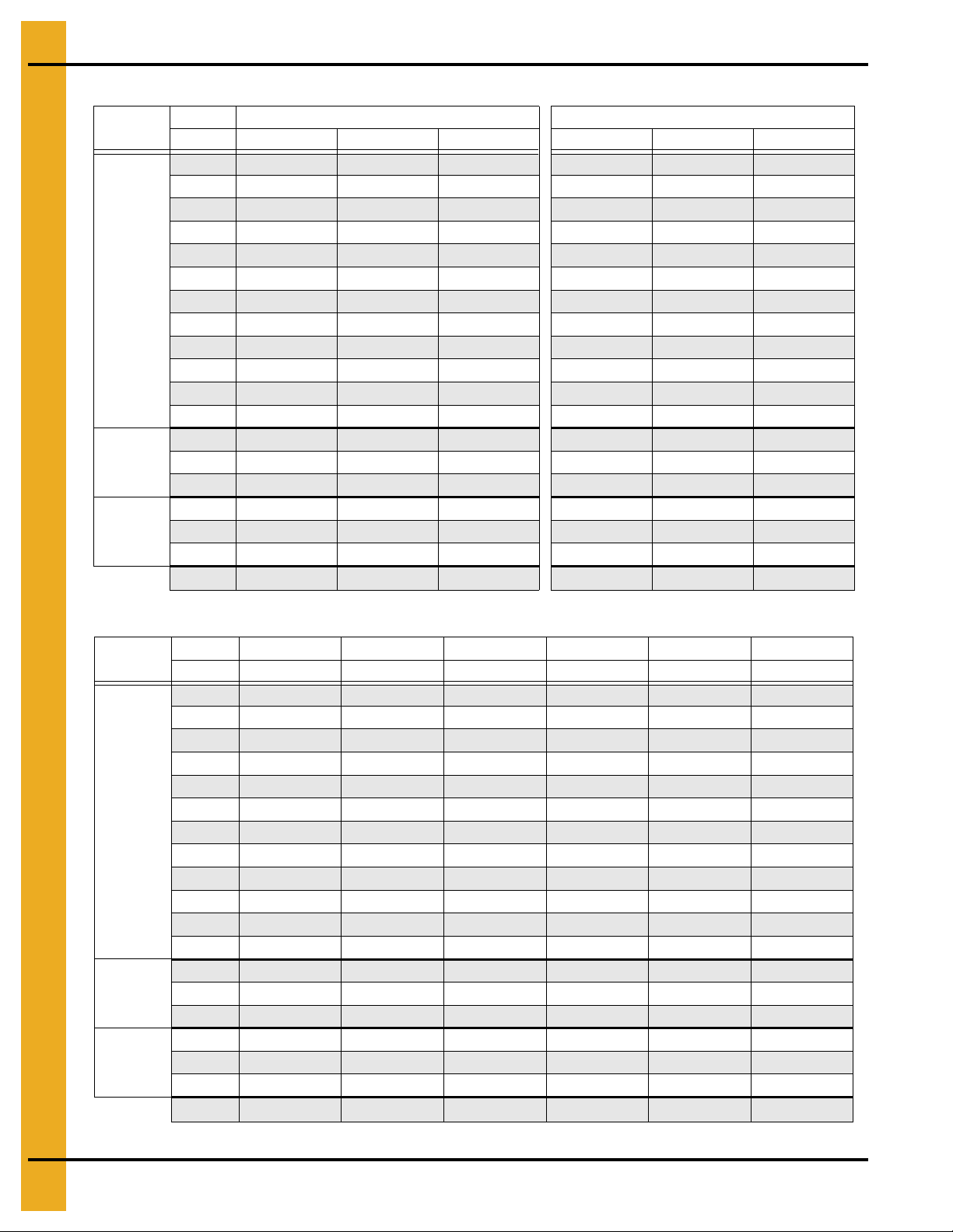
13. T-Cap Foundation 2.66" Outside Stiffened Commercial Tanks
Soil Bearing Capacity: 4000 PSF
Diameter 48
Rebar
Cu. Yds.
Concrete
Rings 28 30 32
A 1'-4" 1'-6" 1'-7" 1'-5" 1'-7" 1'-10"
B 7'-6" 9'-0" 9'-6"
C 24'-11" 24'-11" 24'-11" 27'-11" 27'-11" 27'-11"
D 28'-0" 28'-9" 29'-0"
E 1'-4" 1'-4" 1'-4" 1'-4" 1'-4" 1'-4"
F 1'-1" 1'-2" 1'-4"
G 0'-8" 0'-8" 0'-8" 0'-8" 0'-8" 0'-8"
M 6 #4's 6 #4's 6 #4's
N 10 #5's 9 #6's 11 #6's 10 #5's 10 #6's 12 #6's
P #5 @ 8" c/c #6 @ 9" c/c #6 @ 9" c/c
Q #5 @ 16" c/c #6 @ 18" c/c #6 @ 18" c/c #5 @ 16" c/c #6 @ 18" c/c #6 @ 18" c/c
R #4 @ 12" c/c #5 @ 12" c/c #5 @ 12" c/c
#4 (ft.) 4400 2000 2000 2900 0 0
#5 (ft.) 11200 8000 8100
#6 (ft.) 0 6000 6500 0 7100 8200
Footing 58 78 86
Wall 32 32 32 35 35 35
Floor 63 68 74
Total 153 178 192 186 213 251
28 30 32
8'-0" 9'-0" 10'-0"
31'-3" 31'-9" 32'-3"
1'-1" 1'-3" 1'-6"
5 #5's 5 #5's 5 #5's
#5 @ 8" c/c #6 @ 9" c/c #6 @ 9" c/c
#4 @ 12" c/c #5 @ 12" c/c #5 @ 12" c/c
12600 11200 11500
73 92 118
78 86 98
54
Soil Bearing Capacity: 4000 PSF
Diameter 60 72 75 78 90 105
Rings282828282828
A 1'-6" 1'-9" 1'-9" 1'-9" 1'-11" 2'-1"
B 8'-6" 9'-6" 10'-0" 10'-0" 11'-0" 12'-0"
C 30'-10" 36'-10" 38'-4" 39'-10" 45'-10" 53'-3"
D 34'-5" 40'-11" 42'-8" 44'-2" 50'-8" 58'-9"
E 1'-4" 1'-4" 1'-4" 1'-4" 1'-4" 1'-6"
F 1'-3" 1'-6" 1'-6" 1'-6" 1'-8" 1'-11"
G 0'-8" 0'-8" 0'-8" 0'-8" 0'-8" 0'-8"
M 5 #5's 6 #5's 6 #5's 5 #6's 6 #6's 7 #6's
N 9 #6's 11 #6's 12 #6's 12 #6's 14 #6's 16 #6's
P #5 @ 8" c/c #6 @ 9" c/c #6 @ 9" c/c #6 @ 8" c/c #6 @ 8" c/c #6 @ 8" c/c
Q #5 @ 16" c/c #6 @ 18" c/c #6 @ 18" c/c #6 @ 16" c/c #6 @ 16" c/c #6 @ 16" c/c
R #4 @ 12" c/c #4 @ 12" c/c #4 @ 12" c/c #4 @ 12" c/c #5 @ 12" c/c #5 @ 12" c/c
#4 (ft.) 3200 4100 4200 4400 0 0
Rebar
Cu. Yds.
Concrete
#5 (ft.) 13900 13700 14800 12800 21700 28700
#6 (ft.) 3500 10100 11200 14900 19600 25800
Footing 91 141 155 161 223 308
Wall 39 46 48 50 58 75
Floor 101 154 167 178 244 349
Total 231 341 370 389 525 732
86 PNEG-318 Concrete Foundation Recommendations for GSI Grain Bins
Page 87

13. T-Cap Foundation 2.66" Outside Stiffened Commercial Tanks
Soil Bearing Capacity: 4000 PSF
Diameter 60 72 75 78 90 105
Rings303030303030
A 1'-8" 1'-11" 1'-11" 2'-0" 2'-2" 2'-3"
B 9'-10" 11'-0" 11'-4" 11'-6" 12'-4" 13'-6"
C 30'-10" 36'-10" 38'-4" 39'-10" 45'-10" 53'-3"
D 35'-1" 41'-8" 43'-4" 44'-11" 51'-4" 59'-6"
E 1'-4" 1'-4" 1'-4" 1'-4" 1'-4" 1'-6"
F 1'-5" 1'-7" 1'-8" 1'-9" 1'-11" 2'-1"
G 0'-8" 0'-8" 0'-8" 0'-8" 0'-10" 0'-10"
M 6 #5's 6 #5's 5 #6's 5 #6's 6 #6's 7 #6's
N 11 #6's 14 #6's 15 #6's 15 #6's 18 #6's 20 #6's
P #6 @ 9" c/c #6 @ 8" c/c #6 @ 8" c/c #6 @ 8" c/c #6 @ 8" c/c #6 @ 7" c/c
Q #6 @ 18" c/c #6 @ 16" c/c #6 @ 16" c/c #6 @ 16" c/c #6 @ 16" c/c #6 @ 14" c/c
R #5 @ 12" c/c #5 @ 12" c/c #5 @ 12" c/c #5 @ 12" c/c #5 @ 12" c/c #5 @ 12" c/c
#4 (ft.) 0 0 0 0 0 0
Rebar
Cu. Yds.
Concrete
#5 (ft.) 13600 18100 16400 17700 22300 29300
#6 (ft.) 8500 13000 16600 17400 23000 31300
Footing 117 180 192 211 282 374
Wall 39 46 48 50 58 75
Floor 111 164 182 200 297 414
Total 267 390 422 461 637 863
Soil Bearing Capacity: 4500 PSF
Diameter 60 72 75 78 90
Rings 32 32 32 32 32
A 1'-9" 1'-11" 2'-0" 2'-0" 2'-3"
B 9'-6" 10'-6" 10'-10" 10'-10" 12'-0"
C 30'-10" 36'-10" 38'-4" 39'-10" 45'-10"
D 34'-11" 41'-5" 43'-1" 44'-7" 51'-2"
E 1'-4" 1'-4" 1'-4" 1'-4" 1'-4"
F 1'-5" 1'-8" 1'-8" 1'-9" 1'-11"
G 0'-8" 0'-8" 0'-10" 0'-10" 0'-10"
M 6 #5's 5 #6's 5 #6's 6 #6's 6 #6's
N 12 #6's 14 #6's 14 #6's 14 #6's 18 #6's
P #6 @ 9" c/c #6 @ 8" c/c #6 @ 8" c/c #6 @ 8" c/c #6 @ 8" c/c
Q #6 @ 18" c/c #6 @ 16" c/c #6 @ 16" c/c #6 @ 16" c/c #6 @ 16" c/c
R #5 @ 12" c/c #5 @ 12" c/c #5 @ 12" c/c #5 @ 12" c/c #5 @ 12" c/c
#4 (ft.) 0 0 0 0 0
Rebar
Cu. Yds.
Concrete
#5 (ft.) 13600 15300 16300 17500 22300
#6 (ft.) 8500 15000 15900 17000 22800
Footing 118 171 191 200 285
Wall 39 46 48 50 58
Floor 110 167 198 217 296
Total 267 384 437 467 639
PNEG-318 Concrete Foundation Recommendations for GSI Grain Bins 87
Page 88

13. T-Cap Foundation 2.66" Outside Stiffened Commercial Tanks
Soil Bearing Capacity: 5000 PSF
Bin Diameter (ft.)60727578
Rings34343434
A 1'-10" 2'-0" 2'-1" 2'-4"
B 9'-9" 10'-10" 11'-3" 11'-3"
C 30'-10" 36'-10" 38'-4" 39'-10"
D 35'-0" 41'-6" 43'-4" 44'-9"
E 1'-4" 1'-4" 1'-4" 1'-4"
F 1'-6" 1'-8" 1'-9" 1'-9"
G 0'-8" 0'-8" 0'-10" 0'-10"
M 6-#5's Each Face 6-#6's Each Face 5-#6's Each Face 6-#6's Each Face
N 12-#6's Each Face 16-#6's Each Face 16-#6's Each Face 16-#6's Each Face
P #6 @ 8" c/c #6 @ 8" c/c #6 @ 8" c/c #6 @ 8" c/c
Q #6 @ 16" c/c #6 @ 16" c/c #6 @ 16" c/c #6 @ 16" c/c
R #5 @ 12" c/c #5 @ 12" c/c #5 @ 12" c/c # 5 @ 12" c/c
#4 (ft.) 0 0 0 0
Rebar
yd^3
Concrete
#5 (ft.) 13600 15300 16400 17500
#6 (ft.) 7100 12200 13200 14300
Footing 126 183 206 222
Wall 38 45 47 49
Floor 114 167 203 217
Total 278 395 456 488
Rebar
yd^3
Concrete
Bin Diameter (ft.) 90
Rings 34
A 2'-4"
B 12'-3"
C 45'-10"
D 51'-3"
E 1'-4"
F2'-0"
G 0'-10"
M 7-#6's Each Face
N 20-#6's Each Face
P #7 @ 9" c/c
Q #6 @ 18" c/c
R #5 @ 12" c/c
#5 (ft.) 22400
#6 (ft.) 11800
#7 (ft.) 6000
Footing 301
Wall 57
Floor 303
Total 661
Rebar
yd^3
Concrete
Bin Diameter (ft.) 105
Rings 33
A 2'-5"
B 13'-9"
C 53'-3"
D 59'-4"
E 1'-6"
F2'-3"
G 0'-10"
M 6-#7's Each Face
N 22-#6's Each Face
P #7 @ 8" c/c
Q #6 @ 16" c/c
R#5 @ 12" c/c
#5 (ft.) 29300
#6 (ft.) 10700
#7 (ft.) 12600
Footing 406
Wall 74
Floor 429
Total 909
88 PNEG-318 Concrete Foundation Recommendations for GSI Grain Bins
Page 89

NC (2.66" Corrugation)
Outside Stiffened Anchor Bolt Chord Charts
2 Post and 3 Post Commercial Tanks
(NCL Series)
®
Section 14
PNEG-318 Concrete Foundation Recommendations for GSI Grain Bins 89
Page 90

14. Outside Universal Stiffened Anchor Bolt Charts
Outside Universal Stiffened Anchor Bolt Charts 2.66" Corrugation
Commercial Tanks
Prior to setting any anchor bolts, you must be sure to have the correct anchor bolt placement chart. This
is very critical for stiffener alignment during erection.
The charts are divided up based on the following criteria:
• Does your bin have 2 or 3 stiffeners per sidewall sheet?
• What diameter of bin do you have?
Refer to proper chart on Pages 91-96 to find the anchor chord that corresponds to the bin that is going to
be built.
Start with one anchor bolt and work from it to the left to locate one quarter of the anchor bolts the n to the
right to locate another quarter of the bolts. Now work off of the last anchor bolt s in each quarter t o lo cate
remaining anchor bolts in the last two (2) quarters.
Figure 14A
90 PNEG-318 Concrete Foundation Recommendations for GSI Grain Bins
Page 91

14. Outside Universal Stiffened Anchor Bolt Charts
2 Stiffener per Sidewall Sheet Anchor Bolt Placement Charts
Nominal 12 Anchors
Diameter
Bolt Radius
Anchor Chord
Nominal 14 Anchors
Diameter
Bolt Radius
Anchor Chord
Nominal
Diameter
Bolt Radius
Anchor Chord
= 18' 2 Post
= 9' - 4-3/16"
4' - 10-1/8"
9' - 4-1/4"
13' - 2-3/4"
= 21' 2 Post
= 10' - 10-1/8"
4' - 9-15/16"
9' - 4-15/16"
13' - 6-5/16"
16 Anchors
= 24' 2 Post
= 12'-4"
4' - 9-13/16"
9' - 5-5/16"
13' - 8-1/2"
17' - 5-3/8"
Nominal 20 Anchors
Diameter
Bolt Radius
Anchor Chord
Nominal
Diameter
Bolt Radius
Anchor Chord
Nominal
Diameter
= 30' 2 Post
= 15' - 3-13/16"
4' - 9-9/16"
9' - 5-5/8"
13' - 10-15/16"
18' - 1/8"
21'-8"
22 Anchors
= 33' 2 Post
= 16' - 9-3/4"
4' - 9-7/16"
9' - 5-11/16"
13' - 11-5/8"
18' - 2-3/16"
22'-1/4"
24 Anchors
= 36' 2 Post
Nominal
Diameter
Bolt Radius
Anchor Chord
18 Anchors
= 27' 2 Post
= 13' - 9-7/8"
4' - 9-11/16"
9' - 5-9/16"
13' - 9-15/16"
17' - 9-3/8"
Bolt Radius
Anchor Chord
= 18' - 3-5/8"
4' - 9-3/8"
9' - 5-3/4"
14'-1/8"
18' - 3-11/16"
22' - 3-7/16"
25' - 10-11/16"
NOTE: The tables on this page are for 2 post outside stiffened tanks only.
PNEG-318 Concrete Foundation Recommendations for GSI Grain Bins 91
Page 92

14. Outside Universal Stiffened Anchor Bolt Charts
2 Stiffener per Sidewall Sheet Anchor Bolt Placement Charts (Continued)
Nominal 28 Anchors
Diameter
Bolt Radius
Anchor Chord
Nominal
Diameter
Bolt Radius
Anchor Chord
= 42' 2 Post
= 21' - 3-1/2"
4' - 9-1/4"
9' - 5-3/4"
14'-3/4"
18' - 5-11/16"
22' - 7-7/8"
26' - 6-3/4"
30' - 1-5/16"
32 Anchors
= 48' 2 Post
= 24' - 3-1/4"
4' - 9-1/8"
9' - 5-11/16"
14' - 1-1/8"
18' - 6-15/16"
22' - 10-5/8"
26' - 1 1 -11/16"
30' - 9-9/16"
Nominal 36 Anchors
Diameter
Bolt Radius
Anchor Chord
Nominal
Diameter
Bolt Radius
Anchor Chord
= 54' 2 Post
= 27'-3"
4' - 9-1/16"
9' - 5-5/8"
14' - 1-5/16"
18' - 7-3/4"
23'-1/2"
27' - 3-1/8"
31' - 3-1/4"
35'-1/2"
38' - 6-9/16"
40 Anchors
= 60' 2 Post
= 30' - 2-7/8"
4'-9"
9' - 5/16"
14' - 1-7/16"
18' - 8-5/16"
23' - 1-3/4"
27' - 5-1/2"
31' - 7-1/4"
35' - 6-5/8"
39' - 3-3/8"
34' - 3-15/16"
42' - 9-1/4"
NOTE: The tables on this page are for 2 post outside stiffened tanks only.
92 PNEG-318 Concrete Foundation Recommendations for GSI Grain Bins
Page 93

14. Outside Universal Stiffened Anchor Bolt Charts
3 Stiffener per Sidewall Sheet Anchor Bolt Placement Charts
Nominal 21 Anchors
Diameter
Bolt Radius
Anchor Chord
Nominal 24 Anchors
Diameter
Bolt Radius
Anchor Chord
= 21' 3 Post
= 10' - 10-1/8"
3' - 2-13/16"
6' - 4-3/4"
9' - 4-15/16"
12' - 2-5/8"
14' - 9-1/8"
= 24' 3 Post
= 12'-4"
3' - 2-11/16"
6' - 4-11/16"
9' - 5-5/16"
12' - 4-1/8"
15'-1/4"
17' - 5-3/8"
Nominal 30 Anchors
Diameter
Bolt Radius
Anchor Chord
Nominal
Diameter
Bolt Radius
Anchor Chord
= 30' 3 Post
= 15' - 3-13/16"
3' - 2-7/16"
6' - 4-1/2"
9' - 5-5/8"
12' - 5-9/16"
15' - 3-7/8"
18'-1/8"
20' - 6-1/16"
33 Anchors
= 33' 3 Post
= 16' - 9-3/4"
3' - 2-3/8"
6' - 4-3/8"
9' - 5-11/16"
12'-6"
15' - 4-15/16"
18' - 2-3/16"
20' - 9-7/16"
23' - 2-1/2"
Nominal
Diameter
Bolt Radius
Anchor Chord
27 Anchors
= 27' 3 Post
= 13' - 9-7/8"
3' - 2-9/16"
6' - 4-9/16"
9' - 5-9/16"
12'-5"
15' - 2-3/8"
17' - 9-3/8"
Nominal
Diameter
Bolt Radius
Anchor Chord
36 Anchors
= 36' 3 Post
= 18' - 3-5/8"
3' - 2-5/16"
6' - 4-5/16"
9' - 5-3/4"
12' - 6-1/4"
15' - 5-11/16"
18' - 3-11/16"
21'-0"
23' - 6-7/16"
25' - 10-11/16"
NOTE: The tables on this page are for 3 post outside stiffened tanks only.
PNEG-318 Concrete Foundation Recommendations for GSI Grain Bins 93
Page 94

14. Outside Universal Stiffened Anchor Bolt Charts
3 Stiffener per Sidewall Sheet Anchor Bolt Placement Charts (Continued)
Nominal 42 Anchors
Diameter
Bolt Radius
Anchor Chord
Nominal
Diameter
= 42' 3 Post
= 21' - 3-1/2"
3' - 2-3/16"
6' - 4-3/16"
9' - 5-3/4"
12' - 6-5/8"
15' - 6-11/16"
18' - 5-11/16"
21' - 3-1/2"
23' - 1 1 -1 3/16"
26' - 6-9/16"
28' - 11 -9/16"
48 Anchors
= 48' 3 Post
Nominal 54 Anchors
Diameter = 54' 3 Post
Bolt Radius = 27'-3"
3' - 2-1/16"
6'-4"
9' - 5-5/8"
12' - 6-7/8"
15' - 7-5/8"
18' - 7-3/4"
Anchor Chord
21' - 7-1/8"
24' - 5-5/8"
27' - 3-1/8"
29' - 11-1/2"
32' - 6-11/16"
35'-1/2"
37' - 4-15/16"
Bolt Radius
Anchor Chord
= 24' - 3-1/4"
3' - 2-1/8"
6' - 4-1/16"
9' - 5-11/16"
12' - 6-13/16"
15' - 7-5/16"
18' - 6-15/16"
21' - 5-11/16"
24' - 3-5/16"
26' - 1 1 -11/16"
29' - 6-11/16"
32'-1/8"
34' - 3-15/16"
Nominal
Diameter
Bolt Radius
Anchor Chord
NOTE: The tables on this page are for 3 post outside stiffened tanks only.
60 Anchors
= 60' 3 Post
= 30' - 2-7/8"
3'-2"
6' - 3-7/8"
9' - 5-9/16"
12' - 6-15/16"
15' - 7-7/8"
18' - 8-5/16"
21' - 8-1/8"
24' - 7-1/4"
27' - 5-1/2"
30' - 2-15/16"
32' - 11-5/16"
35' - 6-5/8"
38'-3/4"
40' - 5-11/16"
42' - 9-1/4"
94 PNEG-318 Concrete Foundation Recommendations for GSI Grain Bins
Page 95

14. Outside Universal Stiffened Anchor Bolt Charts
3 Stiffener per Sidewall Sheet Anchor Bolt Placement Charts (Continued)
Nominal 72 Anchors
Diameter
Bolt Radius
Anchor Chord
= 72' 3 Post
= 36' - 2-1/2"
3' - 1-15/16"
6' - 3-3/4"
9' - 5-7/16"
12' - 6-15/16"
15' - 8-1/8"
18' - 8-15/16"
21' - 9-3/8"
24' - 9-1/4"
27' - 8-9/16"
30' - 7-5/16"
33' - 5-5/16"
36' - 2-9/16"
38' - 10-15/16"
41' - 6-1/2"
44' - 1-1/16"
46' - 6-5/8"
48' - 11-1/8"
51' - 2-1/2"
Nominal 78 Anchors
Diameter
Bolt Radius
Anchor Chord
= 78' 3 Post
= 39' - 2-5/16"
3' - 1-15/16"
6' - 3-3/4"
9' - 5-7/16"
12' - 6-15/16"
15' - 8-3/16"
18' - 9-1/8"
21' - 9-3/4"
24' - 9-7/8
27' - 9-9/16"
30' - 8-3/4"
33' - 7-1/4"
36' - 5-3/16"
39' - 2-3/8"
41' - 10-3/4"
44' - 6-3/8"
47' - 1-1/8"
49' - 6-15/16"
51' - 11-13/16"
54' - 3-5/8"
Nominal
Diameter
Bolt Radius
Anchor Chord
75 Anchors
= 75' 3 Post
= 37' - 8-7/16"
3' - 1-15/16"
6' - 3-3/4"
9' - 5-7/16"
12' - 6-15/16"
15' - 8-1/8"
18' - 9-1/16"
21' - 9-9/16"
24' - 9-5/8"
27' - 9-1/8"
30' - 8-1/16"
33' - 6-3/8"
36' - 3-15/16"
39'-3/4"
41' - 8-3/4"
44' - 3-7/8"
46' - 10-1/16"
49' - 3-1/4"
51' - 7-7/16"
Nominal 90 Anchors
Diameter = 90' 3 Post
Bolt Radius
Anchor Chord
= 45' - 1-15/16"
3' - 1-7/8"
6' - 3-5/8"
9' - 5-5/16"
12' - 6-7/8"
15' - 8-1/4"
18' - 9-3/8"
21' - 10-1/4"
24' - 10-13/16"
27' - 10-15/16"
30' - 10-3/4"
33' - 10-1/16"
36' - 8-7/8"
39' - 7-3/16"
42' - 4-7/8"
45'-2"
47' - 10-3/8"
50' - 6-1/8"
53' - 1-1/8"
55' - 7-5/16"
58' - 0-3/4"
60' - 5-5/16"
62' - 8-15/16"
NOTE: The tables on this page are for 3 post outside stiffened tanks only.
PNEG-318 Concrete Foundation Recommendations for GSI Grain Bins 95
Page 96

14. Outside Universal Stiffened Anchor Bolt Charts
3 Stiffener per Sidewall Sheet Anchor Bolt Placement Charts (Continued)
Nominal 105 Anchors
Diameter
Bolt Radius
Anchor Chord
= 105' 3 Post
= 52' - 7-1/2"
3' - 1-13/16"
6' - 3-9/16"
9' - 5-1/4"
12' - 6-13/16"
15' - 8-1/4"
18' - 9-9/16"
21' - 10-5/8"
24' - 11 -7/16"
28'-0"
31' - 0-5/16"
34' - 0-1/4"
36' - 1 1 -1 3/16"
39' - 10-15/16"
42' - 9-11/16"
45'-8"
48' - 5-13/16"
51' - 3-1/16"
53' - 1 1 -1 3/16"
56' - 7-15/16"
59' - 3-7/16"
61' - 10-3/8"
64' - 4-9/16"
66' - 10-1/8"
69' - 2-15/16"
71' - 7-1/16"
73' - 10-3/8"
Nominal 135 Anchors
Diameter
Bolt Radius
Anchor Chord
= 135' 3 Post
= 67' - 6-1/2"
3' - 1-3/4"
6' - 3-7/16"
9' - 5-1/8"
12' - 6-11/16"
15' - 8-1/4"
18' - 9-5/8"
21' - 10-15/16"
25' - 0-1/16"
28' - 1-1/16"
31' - 1-7/8"
34' - 2-7/16"
37' - 2-7/8"
40'-3"
43' - 2-7/8"
46' - 2-7/16"
49' - 1-3/4"
52' - 0-3/4"
54' - 11-3/8"
57' - 9-5/8"
60' - 7-9/16"
63' - 5-1/16"
66' - 2-1/8"
68' - 10-13/16"
71' - 7-1/16"
74' - 2-13/16"
76' - 10-1/16"
79' - 4-7/8"
81' - 11-1/16"
84' - 4-13/16"
86'-10"
89' - 2-5/8"
91' - 6-5/8"
93' - 10-1/16"
NOTE: The tables on this page are for 3 post outside stiffened tanks only.
96 PNEG-318 Concrete Foundation Recommendations for GSI Grain Bins
Page 97

Inverted “T” Foundation Recommendations
for 4" Corrugation Out side Stiffened
Commercial Tanks (WCL Series)
®
Section 15
PNEG-318 Concrete Foundation Recommendations for GSI Grain Bins 97
Page 98

15. Inverted “T” Foundation 4" Outside Stiffened (WCL Series) Commercial Tanks
All foundation specifications shall be construed as
recommendations only. Because of the many
variable conditions in actual installation, GSI
assumes no liability for results arising from the use
of such recommendations.
3000 PSF Soil Bearing Capacity
Inverted “T” Foundation Notes:
1. The foundation design is based on a minimum allowable soil bearing capacity of 3000 PSF. Bearing
capacity of the soils should be determined by geotechnical investigation and be of uniform
bearing capacity.
2. The foundation site must be free of vegetation and debris and well drained.
3. The foundation must be founded below the frost line or constructed on non-expansive frost free fill.
4. All material used for backfill inside the ring wall should be clean, well graded, crushed rock or a
sand-gravel mixture. Backfill should be placed in 6" lifts, 95% compaction.
5. All reinforcement must meet the requirements of ASTM A615 grade 60 deformed bars.
6. Lap all circumferential bars 35 bar diameters and stagger all laps in plans 3'-0". Estimates do not
include end laps.
7. Concrete must have a minimum compressive strength of 3000 PSI at 28 days, 6%-8% air
entrainment, 4" slump.
Figure 15A
98 PNEG-318 Concrete Foundation Recommendations for GSI Grain Bins
Page 99
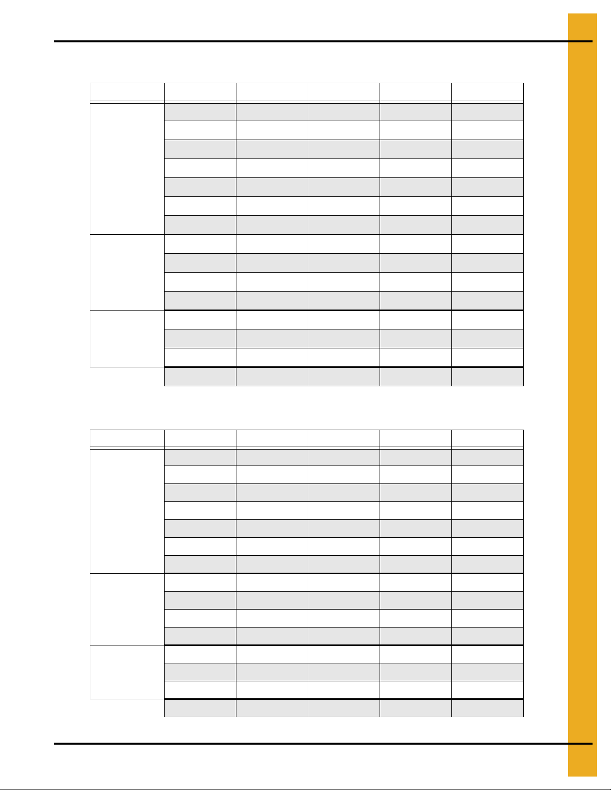
15. Inverted “T” Foundation 4" Outside Stiffened (WCL Series) Commercial Tanks
Diameter of Bin: 24'
Soil Bearing Capacity: 3000 PSF
Ring # 1 2 14 16 18
A 1'-0" 1'-0" 1'-0" 1'-0"
B 3'-2" 3'-11" 4'-10" 5'-7"
C 12'-10" 12'-10" 12'-10" 12'-10"
D 13'-8" 14'-0" 14'-5" 14'-9"
M 5 #4's 5 #4's 5 #4's 5 #4's
N 3 #5's 3 #5's 5 #5's 4 #5's
P #5 @ 14" c/c #5 @ 14" c/c #5 @ 14" c/c #5 @ 11" c/c
#4 (ft.) 2400 2400 2200 2200
Rerod
Cu. Yds.
Concrete
Diameter of Bin: 27'
Soil Bearing Capacity: 3000 PSF
#5 (ft.) 600 600 700 1000
#6 (ft.) 0 0 0 0
#7 (ft.) 0 0 0 0
Footing 9 11 14 16
Wall 15 15 15 15
Floor8888
Total 32 34 37 39
Ring # 1 2 14 16 18
A 1'-0" 1'-0" 1'-0" 1'-0"
B 3'-4" 4'-3" 5'-1" 5'-10"
C 14'-4" 14'-4" 14'-4" 14'-4"
D 15'-3" 15'-8" 16'-0" 16'-4"
M 5 #4's 5 #4's 5 #4's 5 #4's
N 4 #5's 5 #5's 5 #5's 6 #5's
P #5 @ 14" c/c #5 @ 14" c/c #5 @ 14" c/c #6 @ 13" c/c
#4 (ft.) 2700 2700 2700 2700
Rerod
Cu. Yds.
Concrete
#5 (ft.) 700 700 900 600
#6 (ft.) 0 0 0 500
#7 (ft.) 0 0 0 0
Footing 11 14 16 19
Wall 16 16 16 16
Floor 10 10 10 10
Total 37 40 42 45
PNEG-318 Concrete Foundation Recommendations for GSI Grain Bins 99
Page 100

15. Inverted “T” Foundation 4" Outside Stiffened (WCL Series) Commercial Tanks
Diameter of Bin: 30'
Soil Bearing Capacity: 3000 PSF
Ring #12141618
A 1'-0" 1'-0" 1'-0" 1'-0"
B 3'-6" 4'-6" 5'-3" 6'-2"
C 15'-10" 15'-10" 15'-10" 15'-10"
D 16'-10" 17'-3" 17'-7" 18'-0"
M 5 #4's 5 #4's 5 #4's 5 #4's
N 4 #5's 5 #5's 6 #5's 6 #5's
P #5 @ 14" c/c #5 @ 14" c/c #5 @ 13" c/c #6 @ 12" c/c
#4 (ft.) 2900 3100 3100 3100
Rerod
Cu. Yds.
Concrete
Diameter of Bin: 33'
Soil Bearing Capacity: 3000 PSF
#5 (ft.) 800 900 1100 700
#6 (ft.) 0 0 0 500
#7 (ft.) 0 0 0 0
Footing13161922
Wall 18 18 18 18
Floor 13 13 13 13
Total 44 47 50 53
Ring #12141618
A 1'-0" 1'-0" 1'-0" 1'-0"
B 3'-8" 4'-8" 5'-5" 6'-4"
C 17'-4" 17'-4" 17'-4" 17'-4"
D 18'-5" 18'-10" 19'-2 19'-7"
M 5 #4's 5 #4's 5 #4's 5 #4's
N 4 #5's 5 #5's 6 #5's 7 #5's
P #5 @ 14" c/c #5 @ 14" c/c #5 @ 11" c/c #6 @ 11" c/c
#4 (ft.) 3500 3500 3500 3500
Rerod
Cu. Yds.
Concrete
#5 (ft.) 900 1000 1300 800
#6 (ft.) 0 0 0 700
#7 (ft.) 0 0 0 0
Footing15182125
Wall 20 20 20 20
Floor 16 16 16 16
Total 51 54 57 61
100 PNEG-318 Concrete Foundation Recommendations for GSI Grain Bins
 Loading...