

Page 1
Instructions
PNEG-300
1004 East Illinois Street • Assumption, IL 62510 • 1-217-226-4421
Rotary Switch Instructions
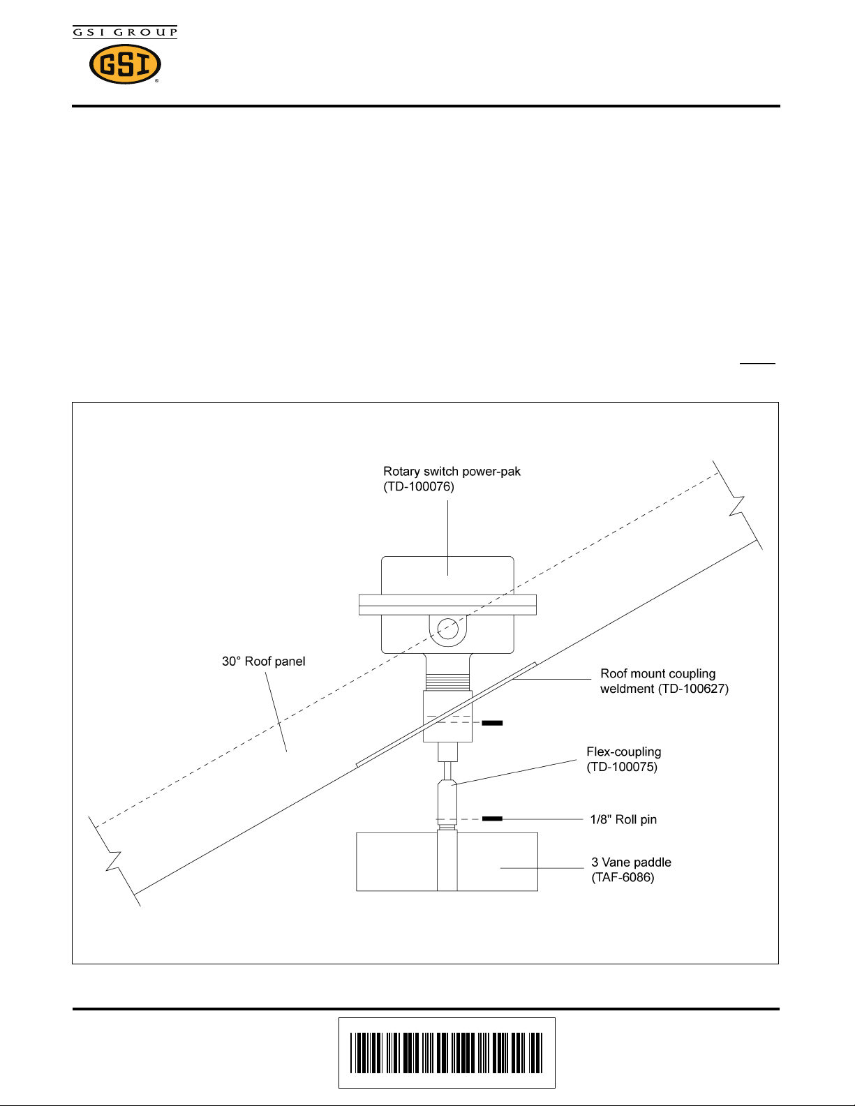
Installation of Roof Mounted Level Switches
Drill 2" diameter holes through roof panels at locations shown on Page 3. Use a mounting plate as a
pattern and drill four (4) 3/8" holes through roof panels at each switch location so the plate can be bolted to
the roof.
Attach flex-coupling to the power-pak. Apply teflon tape or pipe sealant (not included) to power-pak pipe
threads and thread power-pak into mounting plate coupling. Conduit opening in power-pak should be at
right angles to roof rib or face toward eave.
Caulk underside of mounting plate above and both sides of 2" hole. Bolt to roof panel.
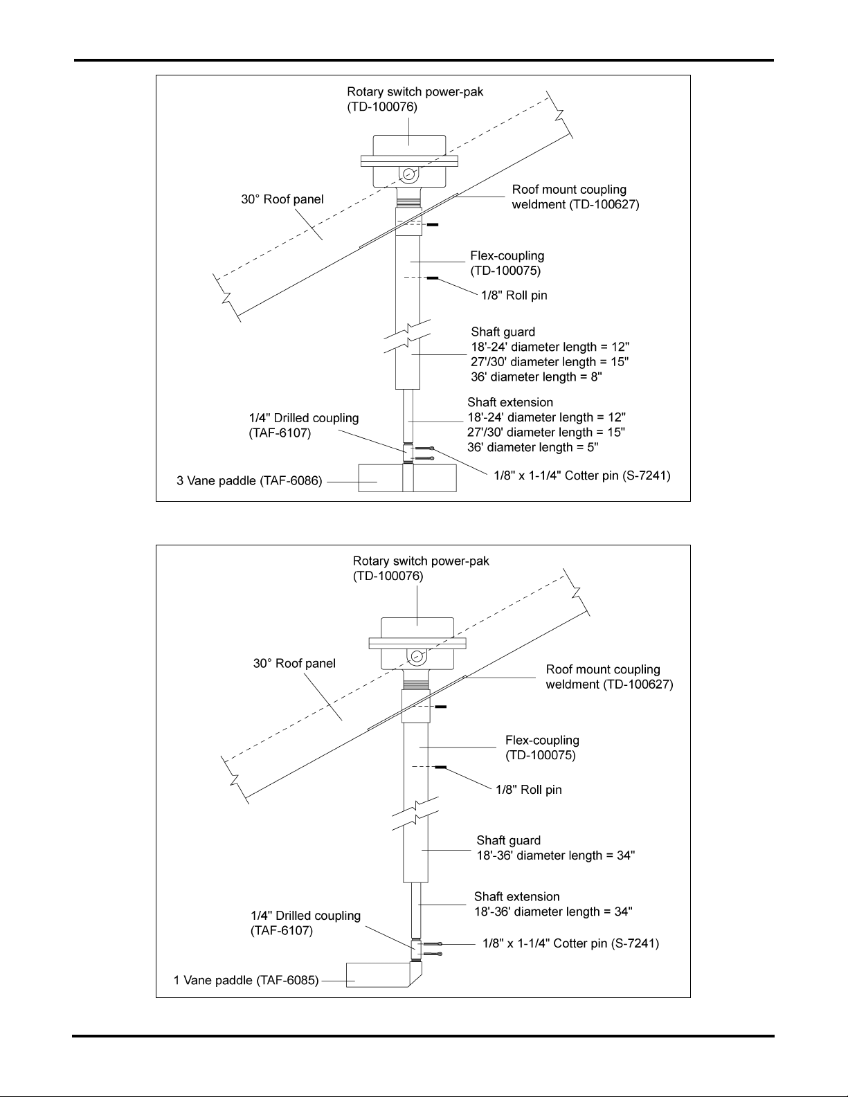
Attach shaft extension according to Figure 2 and Figure 3 on Page 2. Use teflon tape or pipe sealant
(not included) on shaft guard (see Figure 2 and Figure 3 on Page 2 for lengths) and thread to underside
of mount plate coupling. Add 1/4" drilled coupling and paddle. (NOTE: Single vane paddle is used on LOW
level switch.)
Date: 12-16-10
Printed in the U.S.A.
Copyright © 2010 by GSI Group
www.gsiag.com
Figure 1 Overflow Rotary Switch Assembly
PNEG-300
Page 1 of 4
Page 2
Rotary Switch Instructions
Figure 2 High-Limit Rotary Switch Assembly
Figure 3 Low-Limit Rotary Switch Assembly
Page 2 of 4 PNEG-300
Page 3

Rotary Switch Instructions
NOTE: Attach the flex-coupling to the rotary switch
power-pak, then thread the power-pak into the roof mount
coupling before bolting the roof mount to the roof sheet.
Top Dry Bin
Diameter
“A”
18'-24' 23-1/2"
27'/30' 19"
36' 31"
PNEG-300 Page 3 of 4
Figure 4
Page 4

Rotary Switch Instructions
Installation of Wall Mounted Level Switch
Drill 2" hole through wall at desired location. If bin is 2.66" corrugation, hole should be centered on outside
hill. If bin is 4.00" corrugation, hole should be centered on outside valley.
Position mount plate as desired (from inside), mark and drill 3/8" holes. Caulk coupling abundantly where
it passes through wall. Add foam weather strip around top and sides of plate then bolt to bin wall. Caulk
coupling to wall seam from outside.
Attach flex coupling to power-pak. Add teflon tape or pipe sealant (not provided) to power-pak pipe
threads and thread into coupling. Conduit opening should be horizontal or down. Add 1 vane paddle.
(Paddle may be added to flex coupling before power-pak is threaded into coupling if desired.)
Figure 5
Page 4 of 4 PNEG-300
 Loading...