

Page 1
OWNERS MANUAL
ELECTRIC HEATER
VH -_ _ E _ - _
PNEG-269
Page 2

CHECK LIST
üOK
_____ 1. All wire connections
_____ 2. Fuse in place, extra fuse provided
_____ 3. Indicator lights
_____ 4. Unit cycles on to off with thermostat
_____ 5. Hi-coil or coils
_____ 6. Heat up
_____ 7. Lo-coil heats up
Tester Signature___________________________________
Date_________________________
Electric Heater
This equipment shall be installed in accordance
with the current installation codes and applicable
regulations which should be carefully followed in
all cases. Authorities having jurisdiction should be
consulted before installations are made.
2
Page 3

Electric Heater
Roof Warning, Operation & Safety ...........................................................4
Safety Alert Decal ....................................................................................5
Electric Heater Installation .........................................................................6
Checklist Before Installing Electric Heater .............................................6
Installation Instructions .........................................................................6
Heater Specifications ............................................................................7
Heater Electrical Installation (230V Fans) .............................................8
Machine To Earth Grounding ................................................................9
Proper Installation Of Ground Rod ............................................................9
Electric Heater Operation ........................................................................10
Start Up ..............................................................................................10
Service ............................................................................................... 10
Troubleshooting Chart .........................................................................10
Electric Heater Parts ................................................................................ 11
18" Electric Heater .............................................................................. 11
TABLE OF CONTENTS
18" Electric Heater Control Box (2 Element) ........................................12
24" Electric Heater .............................................................................. 13
24" Electric Heater Control Box (2 Element) ........................................14
28"Electric Heater ............................................................................... 15
28" Electric Heater Control Box (3 Element) ........................................16
Electric Heater Wiring .............................................................................. 17
240V 1 Phase 2 Element .....................................................................17
240V 1 Phase 3 Element .....................................................................18
230V 3 Phase Schematic and Wiring ...................................................19
460V 3 Phase Schematic and Wiring ...................................................20
Notes ......................................................................................................21
Warranty .................................................................................................22
3
Page 4
SAFETY
SAFETY FIRST
General Safety Statements
The GSI Group Incs Principal concern is your
safety and the safety of others associated with grain
handling equipment. We want to keep you as a customer. This manual is to help you understand safe
operating procedures and some problems which may
be encountered by the operator and other personnel.
As owner and/or operator, it is your responsibility to know what requirements, hazards and precautions exist and inform all personnel associated with,
or in the area of the product. Safety precautions may
be required from the personnel. This product is ideal
for the conditioning of corn, soy beans or other select
grains. Avoid any alteration to the equipment, such
alterations may produce a very dangerous situation,
where serious injury or death may occur.
Electric Heater
CAUTION
CAUTION indicates a potentially hazardous situation
which, if not avoided, may result in minor or moderate
injury.
CAUTION
CAUTION used without the safety alert symbol indicates
a potentially hazardous situation which, if not avoided,
may result in property damage.
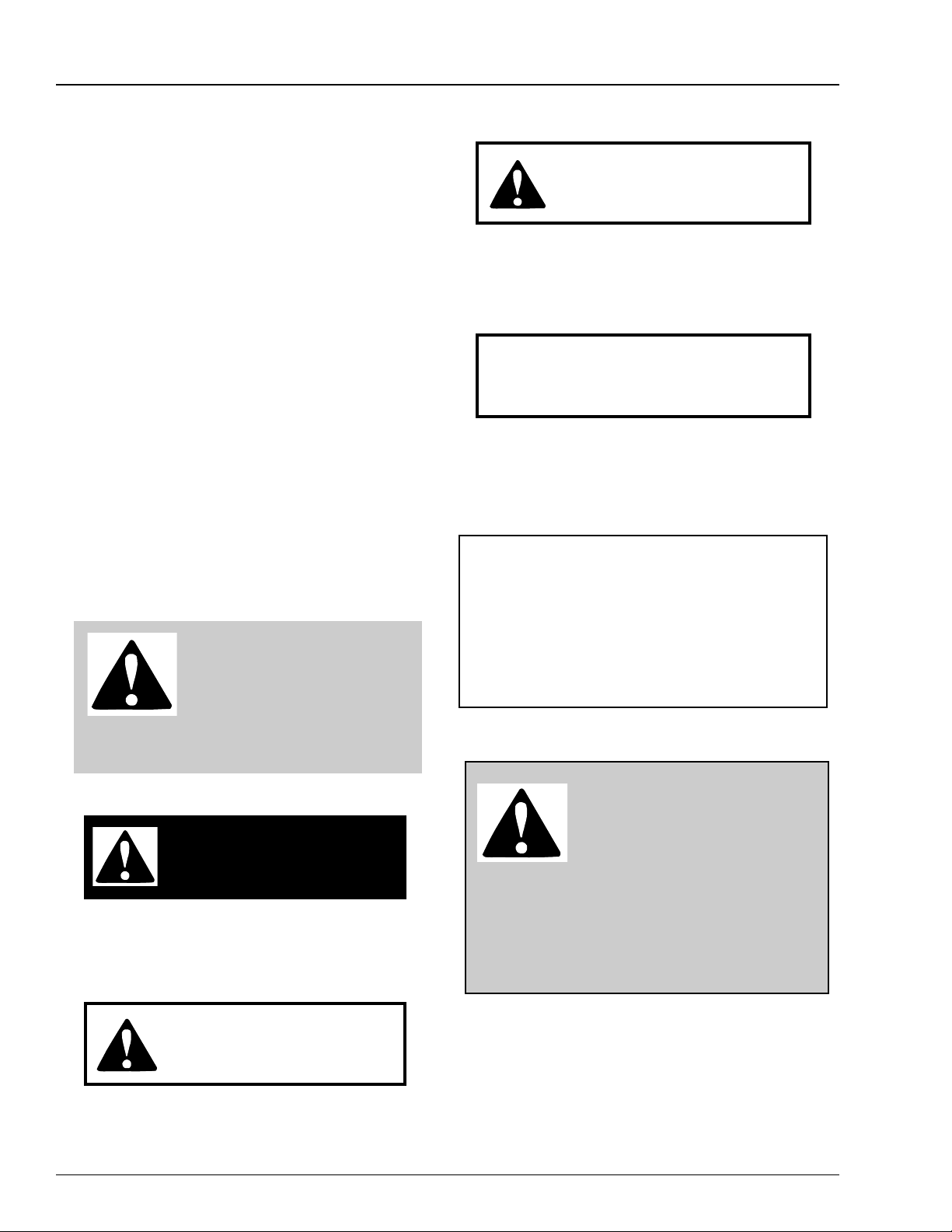
This is the safety alert symbol. It
is used to alert you to potential
personal injury hazards. Obey all
safety messages that follow this
symbol to avoid possible injury or death.
DANGER
DANGER indicates an imminently hazardous situation
which, if not avoided, will result in death or serious injury
If a decal is damaged or missing contact:
The GSI Group Inc.
1004 E. Illinois St.
Assumption, IL 62510
217-226-4421
A free replacement will be sent to you.
BE ALERT!
Danger!
Personnel operating or working
around electrical equipment
should read this manual. This manual must be
delivered with equipment to its owner. Failure
to read this manual and its safety instructions is a
misuse of the equipment.
WARNING
WARNING indicates a potentially hazardous situation
which , if not avoided, could result in death or serious
injury.
4
The GSI Group Inc. recommends that you
contact your local power company and have a representative review your installation so your wiring will
be compatible with their system and so that you will
have adequate power supplied to your unit.
Page 5
Electric Heater
SAFETY
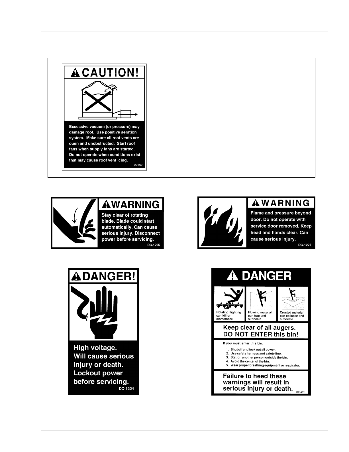
Roof Damage Warning And Disclaimer
GSI DOES NOT WARRANT ANY ROOF DAMAGE CAUSED
BY EXCESSIVE VACUUM OR INTERNAL PRESSURE FROM
FANS OR OTHER AIR MOVING SYSTEMS. ADEQUATE VEN-
TILATION AND/OR "MAKEUP AIR" DEVICES SHOULD BE
PROVIDED FOR ALL POWERED AIR HANDLING SYSTEMS.
GSI DOES NOT RECOMMEND THE USE OF DOWNWARD
FLOW SYSTEMS (SUCTION). SEVERE ROOF DAMAGE CAN
RESULT FROM ANY BLOCKAGE OF AIR PASSAGES. RUN-
NING FANS DURING HIGH HUMIDITY/COLD WEATHER
CONDITIONS CAN CAUSE AIR EXHAUST OR INTAKE PORTS
TO FREEZE.
5
Page 6
INSTALLATION
Electric Heater
Checklist Before
Installing Electric Heater
1. One of the most important factors for installation is providing adequate power to run the unit.
Under sized wire can lead to voltage drop and
can cause overheating of power leads and poor
performance. Therefore, it is necessary to know
the distance from the unit to an available trans
former and the horsepower of your fan unit.
These two factors will determine the size of wire
needed for efficient operation. See Fan Specifications on the following page.
2. Each electric heater circuit should be wired
through a fused or circuit breaker disconnect
switch.
3. Refer to the Heater Specifications on page 7 for
the recommended slow blow fuse or breaker size
to use when installing your particular Heater.
4. Standard electrical safety practices and codes
should be used. Refer to National Electric Code
Standard Handbook by National Fire Protection
Association.
Installation
Instructions
Be Sure Power Is Disconnected And
Locked Out Before Installation!
Failure To Do So May Cause Seri-
ous Injury Or Death.
1. Be sure that the disconnect and the fan are well
grounded. See machine to earth ground page 9.
2. Check all fasteners on heater elements and other
bolted items to make sure they are tight. If
any are loose, check for proper clearance and
retighten. They may have loosened in shipping.
3. Heater should be bolted solidly to fan and transition.
4. Check and retighten all electrical connections.
They may have loosened in shipping.
5. Make all input power connections to heater as
shown on page 8.
5. A qualified electrician should make all electrical wiring installations.
6
Important! Heater Must Be Interlocked To Fan
Or Connected To An Air
Proving Device. In Event Of Fan Failure
Heater Must Be Shutdown.
Page 7
Electric Heater
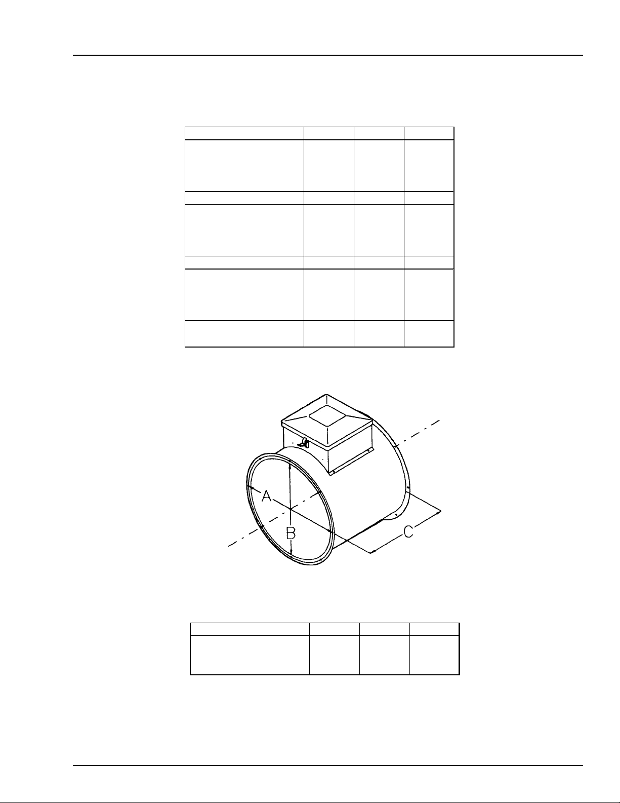
Heater Specifications
Di ameter 18" 24" 28"
Elements
K il owatts
Volt s
Amps
Mi nimum W ire Size Copper Copper Copper
50’ ru n
100’ run
200’ run
300’ run
Minimum Wire Size Alum Al um Alum
50’ ru n
100’ run
200’ run
300’ run
Fuse Size (Time Delay)
Breaker S ize
223
8128
230 230 230
34 52 78
842
842
620
620
620
620
4000
4000
40 60 100
40 60 100
INSTALLATION
Fan 18" 24" 28"
A (Bolt Circl e)
B (Ins id e Di am eter )
C (L ength)
19.1 /2" 25. 3/4" 29. 5/8"
18.1 /4" 24. 1/4" 28. 1/8 "
22" 20" 22.1/2"
7
Page 8

INSTALLATION
Downwind Heater Electrical Installation
Be Sure Power Is
Disconnected And Locked Out
Before Installation!
Failure To Do So May Cause
Serious Injury Or Death.
1. Make field connection of heater
power cord to 5 amp fuse block
in fan as shown in Figure 4.
2. Make field connection of thermostat wires in heater control
box. Thermostat wires are
tagged HI-LIMIT INTERLOCK in heater box.
Electric Heater
Figure 3: Illustration of electric heater wiring installation
on a vane axial or inline fan unit.
Figure 4: Electric heater wiring to fan unit.
8
Page 9

Electric Heater
INSTALLATION
Machine To Earth
Grounding
It is very important that a Machine To Earth Ground Rod be
installed at the fan. The ground
rod needs to be as close to the fan
as possible, but no more than 8
feet away. The ground rod should
be connected to the fan control
panel with at least a #6 solid, bare,
copper ground wire. The grounding rod located at the power pole
will not provide adequate grounding for the fan. The proper
grounding will provide additional
safety if there is a short and will
ensure long life of all circuit
boards used on control circuits,
and the ignition system. The
ground rod must be in accordance
with local requirements.
Figure 4: Use a #6 or approved
size bare copper ground wire.
Install a 5/8" diameter 8' long
copper-clad ground rod, 2'
away from the foundation and
1' below the surface of the
ground or in accordance with
local requirements.
Proper Installation Of Ground Rod
(Ground rods and wires are not supplied by Manufacturer). It is recommended that the rod not be driven into dry ground. Follow these instructions for proper installation.
1. Dig a hole large enough to hold 1 to 2 gallons of water.
2. Fill hole with water.
Dig a hole large enough to hold 1
or 2 gallons of water. Work the
ground rod into the earth until it is
completely in the ground.
3. Insert rod through water and jab it into the ground.
4. Continue jabing the rod up and down. The water will work its
way down the hole, making it possible to work the rod completely into the ground. This method of installation assures
good contact with the surrounding soil, making a proper ground.
5.Connect the bare, copper ground wire to the rod with the
proper ground rod clamp.
6. Connect the bare ground wire to control panel with a grounding lug.
7. Ground wire must not have any breaks or splices. Insulated
wire is not recommended for grounding applications.
Previously Installed Units
It is recommended that previously installed units be checked to see
that a machine to earth ground has been properly installed by an electrician.
9
Page 10

OPERATION
Electric Heater
Start Up
1. Turn thermostat knob to its warmest position.
2. Set heater switches to ON position. Red light
should be lit.
3. Watch thermometer on thermostat housing.
When temperaturereaches desired level turn
thermostat knob slowly to the left until heater
lights go out.
Remember: Electric heaters normally give no more
than 5-15 degrees temperature rise.
4. Observe the heater as it runs through a few cycles
to make sure thermostat is set correctly.
Troubleshooting Chart
Service
All Electric Heater Units are designed and built to withstand use in the most severe environments. Take time
out at least once a year to go over the whole unit and
make sure everything is in working order. Preventive
maintenance can save time and money if done on a regular basis.
1. Always disconnect and lock out the power before working on or around fan motor and electrical components.
2. Malfunctioning electrical components should be
checked by a qualified electrician.
3. Heater elements should be cleaned yearly to
avoid excess dust and dirt build up. Excessive
build up on heater may cause heater to perform
poorly and reduce the life of the heater elements.
Symptom
Heater will not start.
Heater runs for short period of
time and kicks out high limit
switch.
Poor performance
Possible Cause
Blown fuse or breaker in
disconnect switch
Blown fuse in fan control box
Defective wiring or loose
connection
Incorrect wire size
Heater high limit kicked out
Defective thermostat
Thermostat not adjusted
Lack of airflow through heater
Defective high limit switch
Defective element
Remedy
Replace fuses or reset breakers.
Replace fuse.
Follow wiring diagram and tighten
any loose connections.
See wire size charts for proper
wire size and change if needed.
Check manual reset. Push in to
reset.
Replace thermostat.
Adjust thermostat settings.
Check for problems with fan or
obstructions that may be blocking
airflow.
Replace high limit switch.
Replace element.
10
Low line voltage at the installation.
Power failure.
Dirt build up on element
Defective magnetic contactor
Call power company after making
sure wire size is correct.
Clean element.
Replace contactor.
Page 11

Electric Heater
PARTS
18" Electric Heater
11
Page 12

PARTS
Electric Heater
18" Electric Heater Control Box (2 Element)
12
Page 13

Electric Heater
PARTS
24" Electric Heater
13
Page 14

PARTS
Electric Heater
24" Electric Heater Control Box (2 Element)
14
Page 15

Electric Heater
PARTS
28" Electric Heater
15
Page 16

PARTS
Electric Heater
28" Electric Heater Control Box (3 Element)
16
Page 17

Electric Heater
WIRING
240v 1 Phase 2 Element
Schematic
Wiring Diagram
17
Page 18

WIRING
Electric Heater
240v 1 Phase 3 Element
Schematic
18
Wiring Diagram
Page 19

Electric Heater
WIRING
230v 3 Phase Schematic
230v 3 Phase Wiring
Wiring Diagram
19
Page 20

WIRING
Electric Heater
460v 3 Phase Schematic
460v 3 Phase Wiring
20
Wiring Diagram
Page 21

Electric Heater
______________________________________________________________________________________________________________
_____________________________________________________________________________________________________
__________________________________________________________________________________________________________
______________________________________________________________________________________________________
______________________________________________________________________________________________________
____________________________________________________________________________________________________________
_________________________________________________________________________________________________________________
_______________________________________________________________________________________________________________
______________________________________________________________________________________________________________
_____________________________________________________________________________________________________
__________________________________________________________________________________________________________
______________________________________________________________________________________________________
______________________________________________________________________________________________________
NOTES
____________________________________________________________________________________________________________
_________________________________________________________________________________________________________________
_______________________________________________________________________________________________________________
______________________________________________________________________________________________________________
_____________________________________________________________________________________________________
__________________________________________________________________________________________________________
______________________________________________________________________________________________________
______________________________________________________________________________________________________
____________________________________________________________________________________________________________
_________________________________________________________________________________________________________________
_______________________________________________________________________________________________________________
__________________________________________________________________________________________________________
21
Page 22

WARRANTY
Electric Heater
THE GSI GROUP WARRANTS ALL PRODUCTS MANUFACTURED BY THE GSI GROUP TO BE
FREE OF DEFECTS IN MATERIAL AND WORKMANSHIP UNDER NORMAL USAGE AND CONDITIONS FOR A PERIOD OF 12 MONTHS AFTER RETAIL SALE TO THE ORIGINAL END USER
OF SUCH PRODUCTS. THE GSI GROUP'S ONLY OBLIGATION IS, AND PURCHASER'S SOLE
REMEDY SHALL BE FOR THE GSI GROUP, TO REPAIR OR REPLACE, AT THE GSI GROUP'S
OPTION AND EXPENSE, PRODUCTS THAT, IN THE GSI GROUP'S SOLE JUDGMENT, CONTAIN
A MATERIAL DEFECT DUE TO MATERIALS OR WORKMANSHIP. ALL DELIVERY AND SHIPMENT CHARGES TO AND FROM THE GSI GROUP'S FACTORY WILL BE PURCHASER'S RESPONSIBILITY. EXPENSES INCURRED BY OR ON BEHALF OF THE PURCHASER WITHOUT
PRIOR WRITTEN AUTHORIZATION FROM AN AUTHORIZED EMPLOYEE OF THE GSI GROUP
SHALL BE THE SOLE RESPONSIBILITY OF THE PURCHASER.
EXCEPT FOR THE ABOVE STATED EXPRESS LIMITED WARRANTIES, THE GSI GROUP MAKES
NO WARRANTY OF ANY KIND, EXPRESSED OR IMPLIED, INCLUDING, WITHOUT LIMITATION, WARRANTIES OF MERCHANTABILITY OR FITNESS FOR A PARTICULAR PURPOSE OR
USE IN CONNECTION WITH (i) PRODUCT MANUFACTURED OR SOLD BY THE GSI GROUP OR
(ii) ANY ADVICE, INSTRUCTION, RECOMMENDATION OR SUGGESTION PROVIDED BY AN
AGENT, REPRESENTATIVE OR EMPLOYEE OF DMC REGARDING OR RELATED TO THE CONFIGURATION, INSTALLATION, LAYOUT, SUITABILITY FOR A PARTICULAR PURPOSE, OR DESIGN OF SUCH PRODUCT OR PRODUCTS.
IN NO EVENT SHALL THE GSI GROUP BE LIABLE FOR ANY DIRECT, INDIRECT, INCIDENTAL OR CONSEQUENTIAL DAMAGES, INCLUDING, WITHOUT LIMITATION, LOSS OF ANTICIPATED PROFITS OR BENEFITS. PURCHASER'S SOLE AND EXCLUSIVE REMEDY SHALL BE
LIMITED TO THAT STATED ABOVE, WHICH SHALL NOT EXCEED THE AMOUNT PAID FOR
THE PRODUCT PURCHASED. THIS WARRANTY IS NOT TRANSFERABLE AND APPLIES ONLY
TO THE ORIGINAL PURCHASER. THE GSI GROUP SHALL HAVE NO OBLIGATION OR RESPONSIBILITY FOR ANY REPRESENTATIVE OR WARRANTIES MADE BY OR ON BEHALF OF
ANY DEALER, AGENT OR DISTRIBUTOR OF THE GSI GROUP.
THE GSI GROUP ASSUMES NO RESPONSIBILITY FOR FIELD MODIFICATIONS OR ERECTION DEFECTS WHICH CREATE STRUCTURAL OR STORAGE QUALITY PROBLEMS. MODIFICATIONS TO THE PRODUCT NOT SPECIFICALLY COVERED BY THE CONTENTS OF THIS
MANUAL WILL NULLIFY ANY PRODUCT WARRANTY THAT MIGHT HAVE BEEN OTHERWISE AVAILABLE.
THE FOREGOING WARRANTY SHALL NOT COVER PRODUCTS OR PARTS WHICH HAVE
BEEN DAMAGED BY NEGLIGENT USE, MISUSE, ALTERATION OR ACCIDENT. THIS WARRANTY COVERS ONLY PRODUCTS MANUFACTURED BY THE GSI GROUP. THIS WARRANTY
IS EXCLUSIVE AND IN LIEU OF ALL OTHER WARRANTIES EXPRESS OR IMPLIED. THE GSI
GROUP RESERVES THE RIGHT TO MAKE DESIGN OR SPECIFICATION CHANGES AT ANY
TIME.
PRIOR TO INSTALLATION, PURCHASER HAS THE RESPONSIBILITY TO RESEARCH AND
COMPLY WITH ALL FEDERAL, STATE AND LOCAL CODES WHICH MAY APPLY TO THE LOCATION AND INSTALLATION.
22
Page 23

July 2000
 Loading...