

Page 1

PNEG-257
12', 15', 18' and 21' Bulk Feed
Tanks BFT and GHT Series
Assembly Manual
PNEG-257
Date: 01-27-12
Page 2

All information, illustrations, photos and specifications in this manual are based on the latest
information available at the time of publication. The right is reserved to make changes at any
time without notice.
2 PNEG-257 12', 15', 18' and 21' Bulk Feed Tanks BFT and GHT Series
Page 3

Table of Contents
Contents
Chapter 1 Introduction .......................................................................................................................................... 5
Chapter 2 Safety ..................................................................................................................................................... 6
Safety Guidelines .................................................................................................................................. 6
General Safety Statement ..................................................................................................................... 7
Safety Instructions ..................... ... .... .......................................... ... ... ..................................................... 8
Proper Storage of Grain Bin/Silo Materials Prior to Construction ....................................................... 10
Chapter 3 Decals .................................................................................................................................................. 11
Chapter 4 General Information ........................................................................................................................... 14
Bulk Feed Tank Assembly Manual General Instructions .............................. ... ... ................................ 14
Chapter 5 Foundation .......................................................................................................................................... 15
Chapter 6 Sidewall Assembly ............................................................................................................................. 26
Bulk Feed Tank Assembly .................................................................................................................. 26
Sidewall Sheet Orientation (12' Only) ................................................................................................. 27
Sidewall Erection ....................... ... .... ... ... ... ... .......................................... .... ... ... ... .... ... ......................... 28
Chapter 7 Roof ..................................................................................................................................................... 30
Sealed Roof Panel Installation (12'-18' BFT) ...................................................................................... 30
12' Roof Reinforcement Angle ............................................................................................................ 32
Roof Ladder ........................................................................................................................................ 33
12' 60° Roof Cap Ground Control .............................................................................. ... ... ... .... ... ...... ... 36
Roof Cap ............................................................................................................................. .... ... ... ... ... 41
15' and 18' Roof Assembly Instructions .............................................................................................. 42
Raising the Roof ........................ ... .... ... .......................................... ... ... ................................................ 44
Chapter 8 Hopper Assembly ............................................................................................................................... 46
Hopper Sheets .......... .......................................... ... ... .... .......................................... ... ... .......... ............ 46
Hopper Collar Assembly .................................................. ... ... .... ... .......................................... ... ... ...... 49
Chapter 9 Leg and Leg Bracing .......................................................................................................................... 50
12' Only ............................................................................................................................................... 50
Installation of Leg to Sidewall .............................................................................................................. 51
Installation of Leg to Sidewall for 15', 18' and 21' BFT ........................................................................ 52
12'-21' Leg Bracing ............................................................................................................................. 53
Bracing Hole Layouts .................................................................................................................... ... ... 55
Hopper to Leg Bracing .............. ... .... ... ... ... ... .......................................... .... ... ... ... .... ... ... ... ... .......... ... ... 59
Chapter 10 Ladder ............................................................................................................................................... 60
Optional Sidewall Ladder ................................................................................................................... 60
Ladder Safety Cage ........................................................................................................................... 61
Optional Safety Cage ........................................................................................................................ 61
Safety Cage Assembly ...................................................................................................................... 63
Chapter 11 Raising Bin ........................................................................................................................................ 65
Raising Bin to Set on Foundation ...................................................................................................... 65
Chapter 12 Grounding .........................................................................................................
Chapter 13 Pneumatic Fill Kit ............................................................................................................................. 68
Pneumatic Fill Kit Assembly ....... .... ... .......................................... ... ... ... .... ... ... ... .... ... ... ... ... ................ 68
Roof Panel .................................. .......................................... ................................................. ............ 68
................................ 67
PNEG-257 12', 15', 18' and 21' Bulk Feed Tanks BFT and GHT Series 3
Page 4

Table of Contents
Chapter 14 Parts List ........................................................................................................................................... 71
12' Diameter 60° Hopper Bin Specifications .......................... .......................................... .................. 72
12' Diameter 60° Hopper Bin Hardware Specification ........................... .... ... ... ... .... ... ... ... ... .... ... ... ... .. 74
12' Diameter 45° Hopper Bin Specifications .......................... .......................................... .................. 76
12' Diameter 45° Hopper Bin Hardware Specification ........................... .... ... ... ... .... ... ... ... ... .... ... ... ... .. 78
15' Diameter 60° Hopper Bin Specifications .......................... .......................................... .................. 80
15' Diameter 60° Hopper Bin Hardware Specification ........................... .... ... ... ... .... ... ... ... ... .... ... ... ... .. 82
15' Diameter 45° Hopper Bin Specifications .......................... .......................................... .................. 84
15' Diameter 45° Hopper Bin Hardware Specification ........................... .... ... ... ... .... ... ... ... ... .... ... ... ... .. 86
18' Diameter 45° Hopper Bin Specifications .......................... .......................................... .................. 88
18' Diameter 45° Hopper Bin Hardware Specification ........................... .... ... ... ... .... ... ... ... ... .... ... ... ... .. 90
21' Diameter 45° Hopper Bin Specifications .......................... .......................................... .................. 92
21' Diameter 45° Hopper Bin Hardware Specification ........................... .... ... ... ... .... ... ... ... ... .... ... ... ... .. 94
Chapter 15 Warranty ............................................................................................................................................ 97
4 PNEG-257 12', 15', 18' and 21' Bulk Feed Tanks BFT and GHT Series
Page 5

1. Introduction
READ THIS MANUAL carefully to learn how to properly use and install equipment. Failure to do so could
result in personal injury or equipment damage.
INSPECT the shipment immediately upon arrival. The customer is responsible for ensuring that all
quantities are correct. The customer should report and note any damage or shortage on the bill of
lading to justify their claim to the transport company.
THIS MANUAL SHOULD BE CONSIDERED a permanent part of your equipment and should be easily
accessible when needed.
This warranty provides you the assurance that the company will back its products when defects appear
within the warranty period. In some circumstances, the company also provides field improvements, often
without charge to the customer, even if the product is out of warranty. Should the equipment be abused,
or modified to change its performance beyond the factory specifications, the warranty will become void
and field improvements may be denied.
PNEG-257 12', 15', 18' and 21' Bulk Feed Tanks BFT and GHT Series 5
Page 6
2. Safety
This is the safety alert symbol. It is used to alert you
to potential personal injury hazards. Obey all safety
messages that follow this symbol to avoid possible
injury or death.
WARNING indicates a hazardous situation which, if not
avoided, could result in death or serious injury.
CAUTION, used with the safety alert symbol, indicates a
hazardous situation which, if not avoided, could result in
minor or moderate injury.
NOTICE is used to address practices not related to
personal injury.
DANGER indicates a hazardous situation which, if not
avoided, will result in death or serious injury.
Safety Guidelines
This manual contains information that is important for you, the owner/operator, to know and understand.
This information relates to protecting personal safety and preventing equipment problems. It is the
responsibility of the owner/operator to inform anyone operating or working in the area of this equipment
of these safety guidelines. To help you recognize this information, we use the symbols that are defined
below. Please read the manual and pay attention to these sections. Failure to read this manual and its
safety instructions is a misuse of the equipment and may lead to serious injury or death.
DANGER
WARNING
CAUTION
NOTICE
6 PNEG-257 12', 15', 18' and 21' Bulk Feed Tanks BFT and GHT Series
Page 7

2. Safety
This product has sharp edges, which may cause serious injury. To avoid injury, handle
sharp edges with caution and always use proper protective clothing and equipment.
General Safety Statement
Our foremost concern is your safety and the safety of others associated with grain handling equipment.
This manual is to help you understand safe operating procedures and some problems that may be
encountered by the operator and other personnel.
As owner and/or operator, you are responsible to know what requirements, hazard s, and precautions exist
and inform all personnel associated with the equipment or in the area. Safety precautions may be required
from the personnel. Avoid any alterations to the equipment, which may produce a very dangerous
situation, where SERIOUS INJURY or DEATH may occur.
You should consider the location of the bin site relative to power line locations or electrical transmission
equipment. Contact your local power company to review your installation plan or for information
concerning required equipment clearance. Clearance of portable equipment that may be taken to the bin
site should also be reviewed and considered. Any electrical control equipment in contact with the bin
should be properly grounded and installed in accordance with National Electric Code provisions and other
local or national codes.
This product is intended for the use of grain storage only. Any other use is a misuse of the product.
Sidewall bundles or sheets must be stored in a safe manner. The safest method of storing sidewall
bundles is laying horizontally with the arch of the sheet upward, like a dome. Sidewall sheets stored on
edge must be secured so that they cannot fall over and cause injury. Use care when handling and moving
sidewall bundles.
Personnel operating or working around equipment should read this manual. This manual must be
delivered with equipment to its owner. Failure to read this manual and its safety instructions is a
misuse of the equipment.
PNEG-257 12', 15', 18' and 21' Bulk Feed Tanks BFT and GHT Series 7
Page 8
2. Safety
Follow Safety Instructions
Carefully read all safety messages in this manual and
safety signs on your machine. Keep signs in good
condition. Replace missing or damaged safety signs. Be
sure new equipment components and repair parts include
the current safety signs. Replacement safety signs are
available from the manufacturer.
Learn how to operate the machine and how to use controls
properly. Do not let anyone operate without instruction.
Keep your machinery in proper working condition.
Unauthorized modifications to the machine may impair
the function and/or safety and affect machine life.
If you do not understand any part of this manual or need
assistance, contact your dealer.
Read and Understand Manual
Practice Safe Maintenance
Understand service procedures before doing work. Keep area
clean and dry.
Never lubricate, service, or adjust machine while it is in operation.
Keep hands, feet, and clothing away from rotating parts.
Keep all parts in good condition and properly installed. Fix
damage immediately . Replace worn or broken p arts. Remove any
built-up grease, oil, and debris.
Maintain Equipment
and Work Area
Safety Instructions
Our foremost concern is your safety and the safety of others associated with this equipment. We want to
keep you as a customer. This manual is to help you understand safe operating procedures and some
problems that may be encountered by the operator and other personnel.
As owner and/or operator, it is your responsibility to know what requirements, hazards, and precautions
exist, and to inform all personnel associated with the equipment or in the area. Safety precautions may be
required from the personnel. Avoid any alterations to the equipment. Such alterations may p roduce a very
dangerous situation where SERIOUS INJURY or DEATH may occur.
This equipment shall be installed in accordance with the current installation codes and applicable
regulations, which should be carefully followed in all cases. Authorities having jurisdiction should be
consulted before installations are made.
8 PNEG-257 12', 15', 18' and 21' Bulk Feed Tanks BFT and GHT Series
Page 9
2. Safety
Prepare for Emergencies
Be prepared if fire starts.
Keep a first aid kit and fire extinguisher handy.
Keep emergency numbers for doctors, ambulance service,
hospital, and fire department near your telephone.
Keep Emergency Equipment
Quickly Accessible
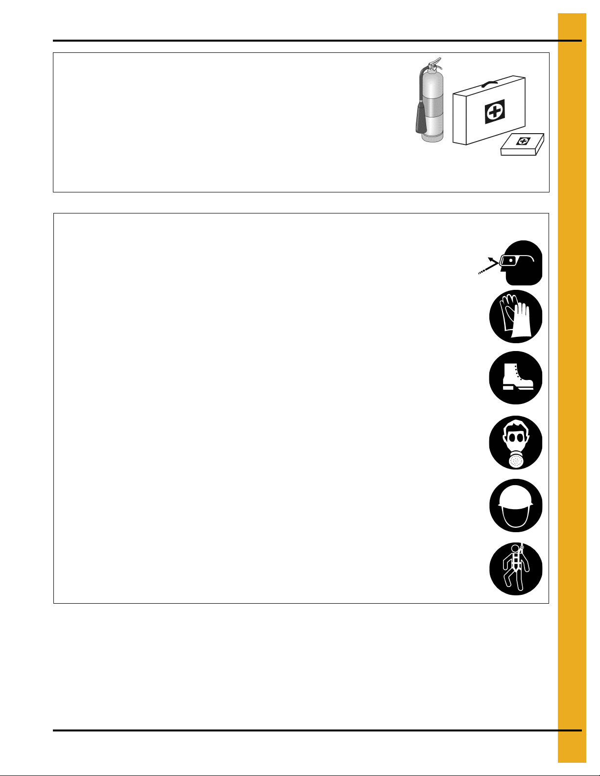
Wear Protective Clothing
Wear close-fitting clothing and safety equipment appropriate
to the job.
Remove all jewelry.
Tie long hair up and back.
Wear safety glasses at all times to protect eyes from debris.
Wear gloves to protect your hands from sharp edges on
plastic or steel parts.
Wear steel toed-boots to help protect your feet from falling
debris. Tuck in any loose or dangling shoestrings.
A respirator may be needed to prevent breathing potentially
toxic fumes and dust.
Wear a hard hat to help protect your head.
Wear appropriate fall protection equipment when working at
elevations greater than six feet (6').
Eye Protection
Gloves
Steel-Toed Boots
Respirator
Hard Hat
Fall Protection
PNEG-257 12', 15', 18' and 21' Bulk Feed Tanks BFT and GHT Series 9
Page 10

2. Safety
Proper Storage of Grain Bin/Silo Materials Prior to Construction
Wet storage stain (rust) will develop when closely packed bundles of galvanized material, such as sidewall
and roof sheets, have moisture present. Inspect roof and sidewall bundles on arrival for any moisture. If
moisture is present, it must not be allowed to remain between the she ets. Separate the sheets or panels
immediately and wipe them down. Spray with a light oil or diesel fuel.
If possible, sidewall bundles, roof sheets and other closely packed galvanized materials should be stored
in a dry, climate controlled building. If outdoor storage is unavoidable, the materials should be stored so
that they are raised above the ground and vegetation. Any stacking an d spacing mat erials sho uld not be
corrosive or wet. Be sure to protect materials from the weather, but permit air movement around the
bundles if possible.
Storing roof bundles and sidewall sheets at a slight incline can also help minimize the presence of
moisture. Storing the bundles with the center of the dome up (like an arch) is one option for minimizing
moisture during storage. Sidewall bundles can also be stored on edge but must be secured so that they
do not fall over and cause injury.
If “white rust” or “wet storage stain” occurs, contact the manufacturer imme diately about ways to minimize
the adverse effect upon the galvanized coating.
10 PNEG-257 12', 15', 18' and 21' Bulk Feed Tanks BFT and GHT Series
Page 11
DC-604 Located on the cap latch control arm.
DC-604
3. Decals
PNEG-257 12', 15', 18' and 21' Bulk Feed Tanks BFT and GHT Series 11
Page 12
3. Decals
Plastic tie
DC-590 Located on the cap latch control arm.
12 PNEG-257 12', 15', 18' and 21' Bulk Feed Tanks BFT and GHT Series
Page 13
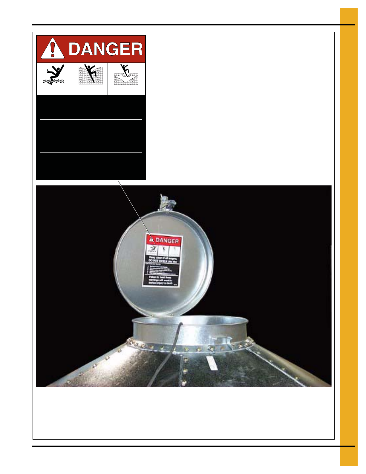
DC-GBC-1A Located on inside the peak cap.
GSI Decals
1004 E. Illinois St.
Assumption, IL. 62510
Phone: 1-217-226-4421
For replacement decals, contact:
Rotating flighting will
kill or dismember.
Flowing material will
trap and suffocate.
Crusted material will
collapse and suffocate.
Keep clear of all augers.
DO NOT ENTER this bin!
Failure to heed these
warnings will result in
serious injury or death.
If you must enter the bin:
1. Shut off and lock out all power.
2. Use a safety harness and safety line.
3. Station another person outside the bin.
4. Avoid the center of the bin.
5. Wear proper breathing equipment or respirator.
DC-GBC-1A
3. Decals
PNEG-257 12', 15', 18' and 21' Bulk Feed Tanks BFT and GHT Series 13
Page 14

4. General Information
Bulk Feed Tank Assembly Manual General Instructions
First, read the assembly manual completely before starting to assemble the Bulk Feed Tank. Check the
shipment with the packing list to be sure there are no shortages.
1. Decal protective mask must be removed when assembling tank. Mask may become difficult to
remove if left exposed to sunlight.
2. Vertical seams must be staggered on all sidewall rings.
3. When legs extend up 2 rings, the leg holes must be in alignment in the bottom 2 rings.
4. All hopper seams and the hopper collar use truss head bolts. The heads of the bolts must be on the
inside of the tank.
5. All bolts are to be tightened from the nut side only. Do not allow bolt heads to spin.
6. Hex head bin bolts are used on all sidewall and roof seams with the bolt heads on the outside of
the bin.
7. Hex head bolts are to be used on all leg to sidewall connections with the bolt heads on the inside of
the tank.
8. Drift punches can be used to align holes.
9. All vertical sidewall sheet seams must be overlapped in the same direction.
10. Close hole spacing is used at the top of all top sidewall sheets and at the bottom of all bottom
sidewall sheets.
Selecting the Proper Site
The selected site should be level, firm and free from underlying debris. The tank can be installed
satisfactorily on slopes, but as the slope increases, additional labor and materials are required for the
foundation. The concrete foundation surfaces must be level
and tamped thoroughly to prevent uneven settling from the weight of the tank. Good water drainage
should be provided to prevent water collecting under or around the tank. Naturally, the site must allow
convenient access for easy loading and unloading, plus provide additional space for future units. Also,
consider the positioning of handling equipment, availability of electricity, etc.
. If some fill is required, it should be watered
Tools
Tools recommended for assembly of Bulk Feed Tanks.
1. Assorted sizes of combination wrenches
2. Hammer
3. 3-12" Long drift punches
4. 1 Large flathead screwdriver
5. 1 Pair of slip joint pliers
6. Two (2) adjustable wrenches
7. Ratchet and sockets
8. Impact wrenches and sockets (if available)
14 PNEG-257 12', 15', 18' and 21' Bulk Feed Tanks BFT and GHT Series
Page 15
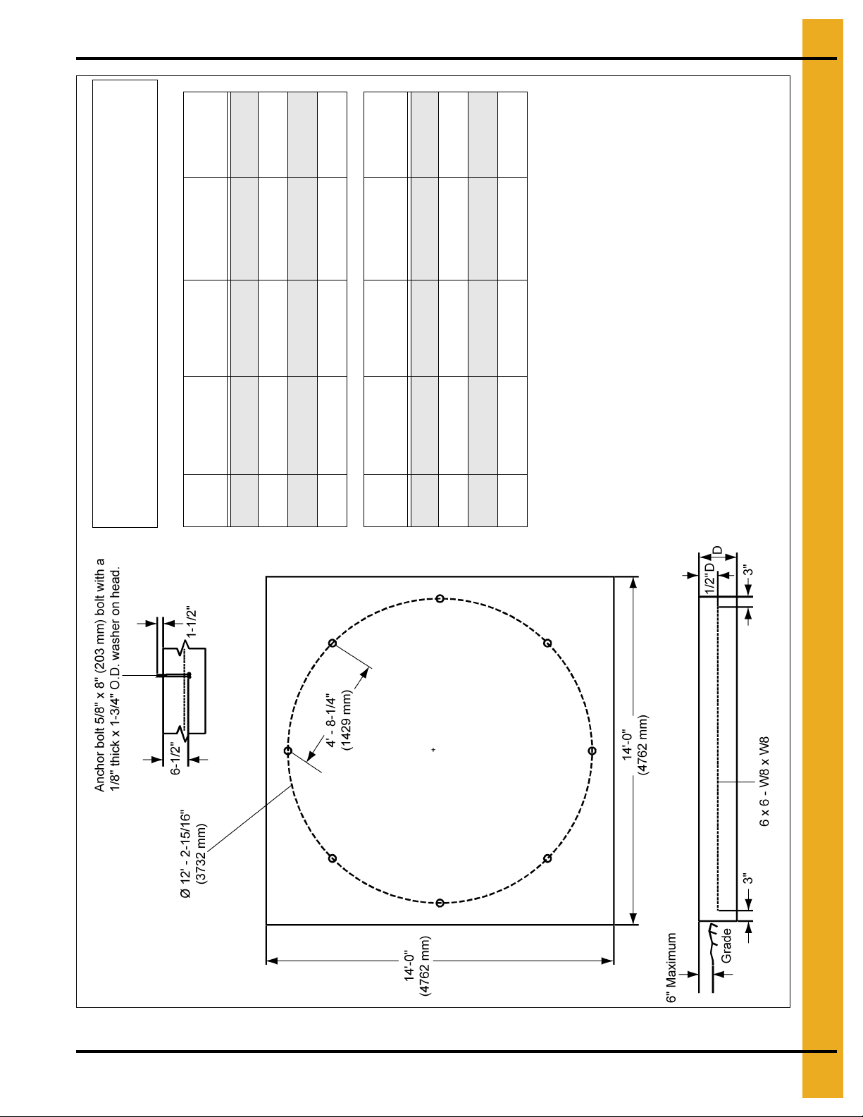
5. Foundation
# of
Rings
Slab
Thickness (D)
Concrete
Volume
Wire Mesh
Area
# of Column
Legs
2-5 15" 9.1 Cu. Yards 196 Sq. Ft. 8
6 16" 9.7 Cu. Yards 196 Sq. Ft. 8
7 16" 9.7 Cu. Yards 196 Sq. Ft. 8
8 17" 10.3 Cu. Yards 196 Sq. Ft. 8
# of
Rings
Slab
Thickness (D)
Concrete
Volume
Wire Mesh
Area
# of Column
Legs
2-5 381 mm 6.93 Cu. Meters 18.21 Sq. Meters 8
6 406 mm 7.40 Cu. Meters 18.21 Sq. Meters 8
7 406 mm 7.40 Cu. Meters 18.21 Sq. Meters 8
8 432 mm 7.86 Cu. Meters 18.21 Sq. Meters 8
GENERAL NOTES:
1. Foundation recommendations are based on 3500 lbs./ft.^2 allowable
soil bearing capacity.
2. Foundation recommendations are based on a minimum compressive
strength of 3000 PSI at 28 days.
3. The foundation site must be free of vegetation and debris and
well drained.
4. The foundation should be level within 1/4" overall and within
± 1/8" in any 10 ft. length along the anchor bolt circle.
5. Material estimates do not include allowance for shrinkage and waste.
6. These layouts are recommendations for GSI tanks only. Consult GSI
engineering for special tank foundations.
* Applies to 45° hopper tank only.
All instructions shall be construed as recommendations only. Because the
actual installation may vary according to local conditions . The GSI Group
assumes no liability for results arising from the use of such recommendations.
*
*
PNEG-257 12', 15', 18' and 21' Bulk Feed Tanks BFT and GHT Series 15
Figure 5A 12' 2-8 Rings BFT/GHT Square Pad
Page 16
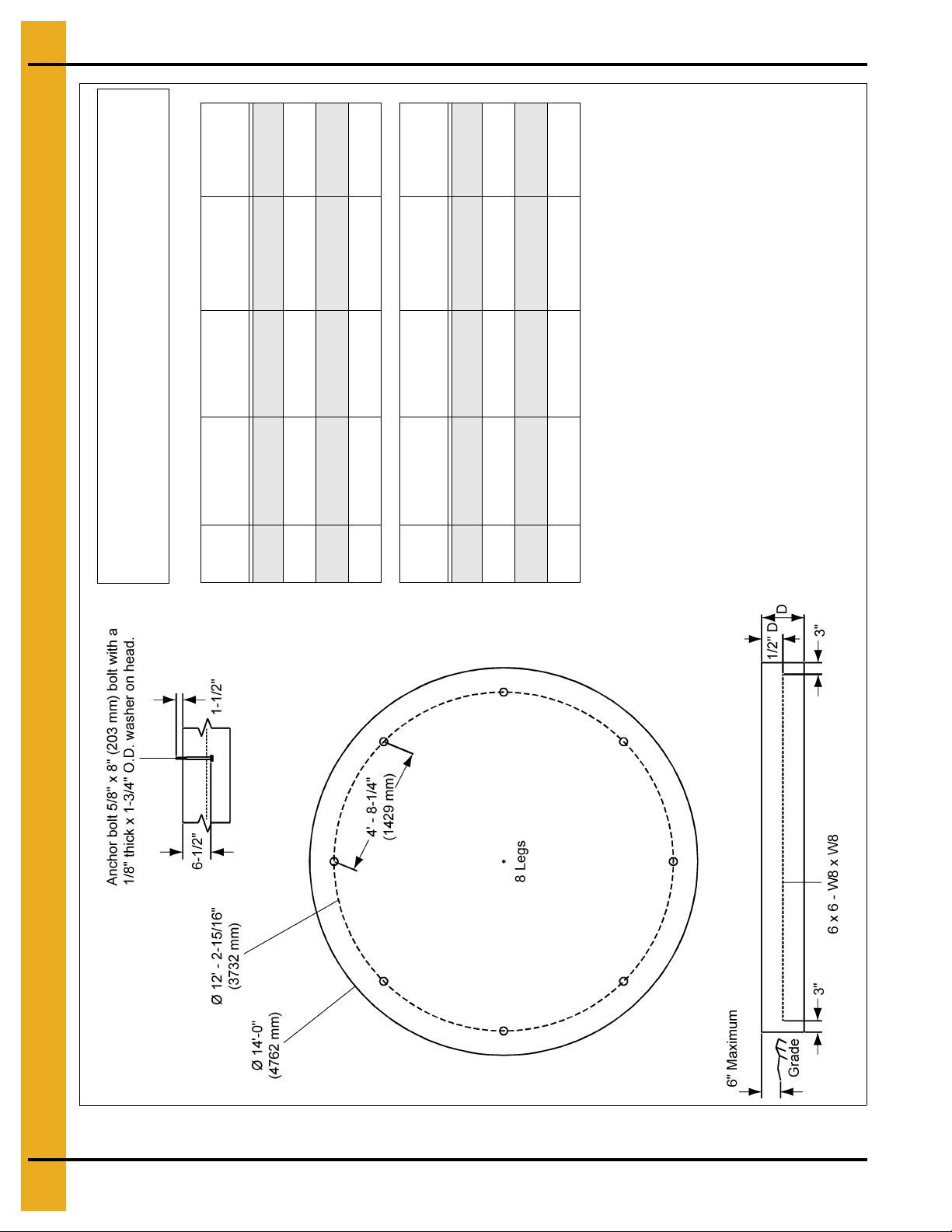
5. Foundation
# of
Rings
Slab
Thickness (D)
Concrete
Volume
Wire Mesh
Area
# of Column
Legs
2-5 15" 7.1 Cu. Y a rd s 155 Sq. Ft. 8
6 16" 7.6 Cu. Yards 155 Sq. Ft. 8
7 16" 7.6 Cu. Ya rd s 155 Sq. Ft. 8
8 17" 8.1 Cu. Yards 155 Sq. Ft. 8
# of
Rings
Slab
Thickness (D)
Concrete
Volume
Wire Mesh
Area
# of Column
Legs
2-5 381 mm 5.45 Cu. Meters 14.40 Sq. Meters 8
6 406 mm 5.81 Cu. Meters 14.40 Sq. Meters 8
7 406 mm 5.81 Cu. Meters 14.40 Sq. Meters 8
8 432 mm 6.18 Cu. Meters 14.40 Sq. Meters 8
GENERAL NOTES:
1. Foundation recommendations are based on 3500 lbs./ft.^2 allowable
soil bearing capacity.
2. Foundation recommendations are based on a minimum compressive
strength of 3000 PSI at 28 days.
3. The foundation site must be free of vegetation and debris and
well drained.
4. The foundation should be level within 1/4" overall and within
± 1/8" in any 10 ft. length along the anchor bolt circle.
5. Material estimates do not include allowance for shrinkage and waste.
6. These layouts are recommendations for GSI tanks only. Consult GSI
engineering for special tank foundations.
* Applies to 45° hopper tank only.
All instructions shall be construed as recommendations only. Because the
actual installation may vary according to local conditions. The GSI Group
assumes no liability for results arising from the use of such recommendations.
*
*
16 PNEG-257 12', 15', 18' and 21' Bulk Feed Tanks BFT and GHT Series
Figure 5B 12' 2-8 Rings BFT/GHT Round Pad
Page 17
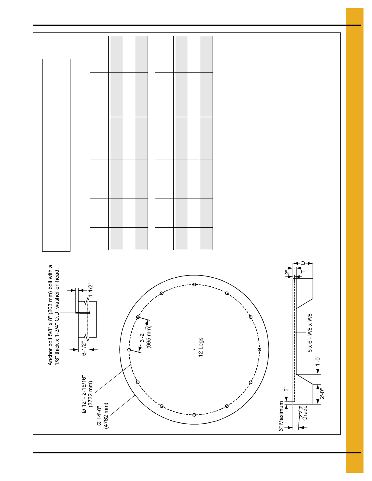
5. Foundation
# of
Rings
Footing
Depth (D)
Slab
Thickness (T)
Concrete
Volume
Wire Mesh
Area
# of Column
Legs
8 15" 4" 5.0 Cu. Yards 175 Sq. Ft. 12
9 18" 4" 5.8 Cu. Yards 175 Sq. Ft. 12
10 20" 4" 6.4 Cu. Yards 175 Sq. Ft. 12
# of
Rings
Footing
Depth (D)
Slab
Thickness (T)
Concrete
Volume
Wire Mesh
Area
# of Column
Legs
8 381 mm 102 mm 3.82 Cu. Meters 16.26 Sq. Meters 12
9 457 mm 102 mm 4.43 Cu. Meters 16.26 Sq. Meters 12
10 508 mm 102 mm 4.89 Cu. Meters 16.26 Sq. Meters 12
GENERAL NOTES:
1. Foundation recommendations are based on 3500 lbs./ft.^2 allowable
soil bearing capacity.
2. Foundation recommendations are based on a minimum compressive
strength of 3000 PSI at 28 days.
3. The foundation site must be free of vegetation and debris and
well drained.
4. The foundation should be level within 1/4" overall and within
± 1/8" in any 10 ft. length along the anchor bolt circle.
5. Material estimates do not include allowance for shrinkage and waste.
6. These layouts are recommendations for GSI tanks only. Consult GSI
engineering for special tank foundations.
* Applies to 60° hopper tank only.
** Applies to 45° and 60° hopper tanks.
All instructions shall be construed as recommendations only. Because the
actual installation may vary according to local conditions. The GSI Group
assumes no liability for results arising from the use of such recommendations.
****
**
Figure 5C 12' 8-10 Rings BFT/GHT Round Pad
PNEG-257 12', 15', 18' and 21' Bulk Feed Tanks BFT and GHT Series 17
Page 18
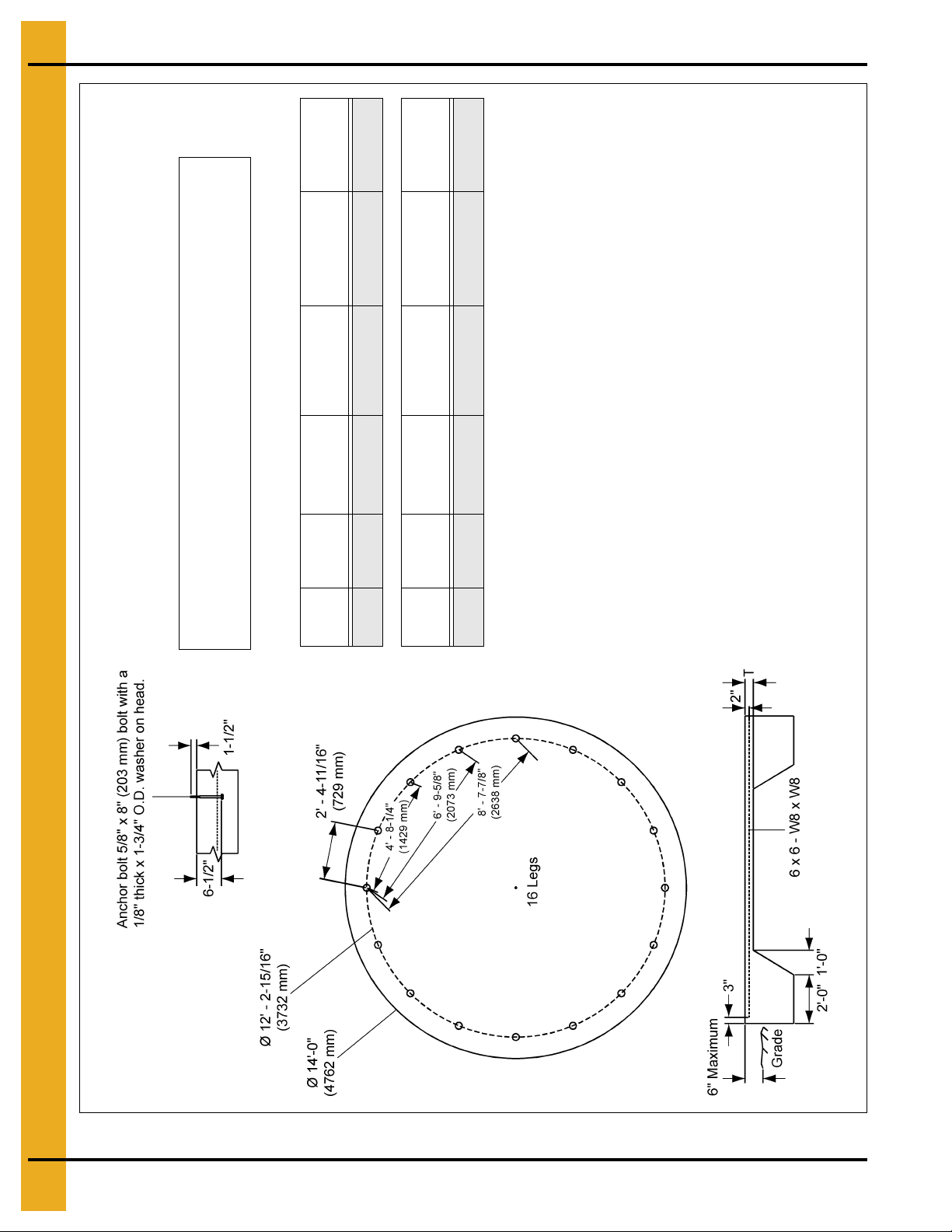
5. Foundation
# of
Rings
Footing
Depth (D)
Slab
Thickness (T)
Concrete
Volume
Wire Mesh
Area
# of Column
Legs
11 24" 4" 7.5 Cu. Yards 175 Sq. Ft. 16
# of
Rings
Footing
Depth (D)
Slab
Thickness (T)
Concrete
Volume
Wire Mesh
Area
# of Column
Legs
11 610 mm 102 mm 5.73 Cu. Meters 16.26 Sq. Meters 16
GENERAL NOTES:
1. Foundation recommendations are based on 3500 lbs./ft.^2 allowable
soil bearing capacity.
2. Foundation recommendations are based on a minimum compressive
strength of 3000 PSI at 28 days.
3. The foundation site must be free of vegetation and debris and
well drained.
4. The foundation should be level within 1/4" overall and within
± 1/8" in any 10 ft. length along the anchor bolt circle.
5. Material estimates do not include allowance for shrinkage and waste.
6. These layouts are recommendations for GSI tanks only. Consult GSI
engineering for special tank foundations.
All instructions shall be construed as recommendations only. Because the
actual installation may vary according to local conditions . The GSI Group
assumes no liability for results arising from the use of such recommendations.
Figure 5D 12' 11 Rings BFT/GHT 16 Leg Round Pad
18 PNEG-257 12', 15', 18' and 21' Bulk Feed Tanks BFT and GHT Series
Page 19
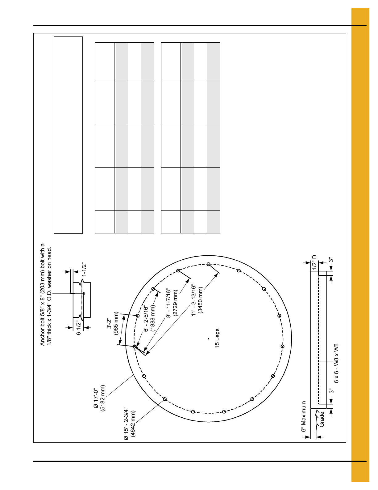
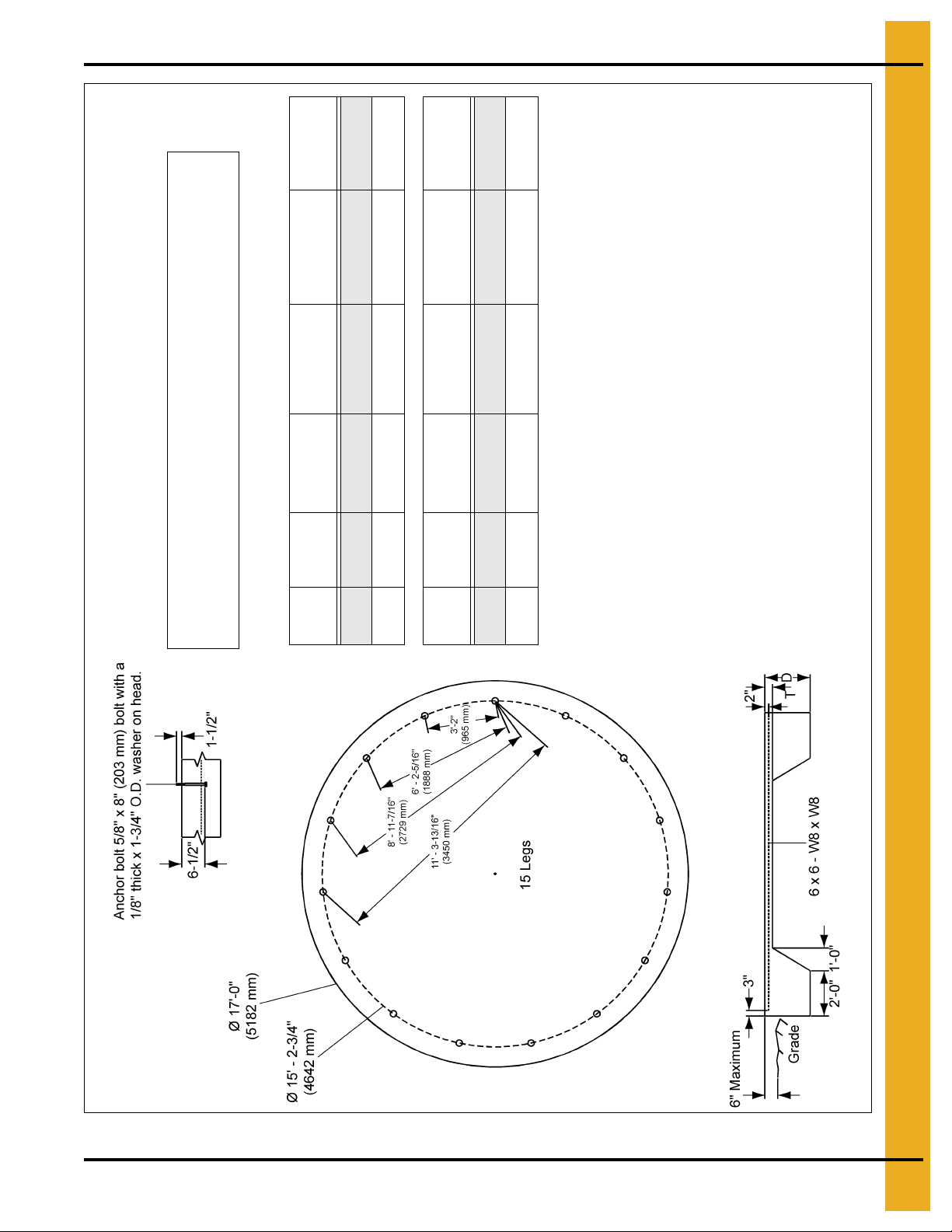
5. Foundation
# of
Rings
Slab
Thickness (D)
Concrete
Volume
Wire Mesh
Area
# of Column
Legs
1-4 14" 11.0 Cu. Yards 255 Sq. Ft. 15
5 15" 11.8 Cu. Yards 255 Sq. Ft. 15
6 16" 12.6 Cu. Yards 255 Sq. Ft. 15
# of
Rings
Slab
Thickness (D)
Concrete
Volume
Wire Mesh
Area
# of Column
Legs
1-4 356 mm 8.41 Cu. Meters 23.69 Sq. Meters 15
5 381 mm 9.01 Cu. Meters 23.69 Sq. Meters 15
6 406 mm 9.63 Cu. Meters 23.69 Sq. Meters 15
GENERAL NOTES:
1. Foundation recommendations are based on 3500 lbs./ft.^2 allowable
soil bearing capacity.
2. Foundation recommendations are based on a minimum compressive
strength of 3000 PSI at 28 days.
3. The foundation site must be free of vegetation and debris and
well drained.
4. The foundation should be level within 1/4" overall and within
± 1/8" in any 10 ft. length along the anchor bolt circle.
5. Material estimates do not include allowance for shrinkage and waste.
6. These layouts are recommendations for GSI tanks only. Consult GSI
engineering for special tank foundations.
All instructions shall be construed as recommendations only. Because the
actual installation may vary according to local conditions. The GSI Group
assumes no liability for results arising from the use of such recommendations.
PNEG-257 12', 15', 18' and 21' Bulk Feed Tanks BFT and GHT Series 19
Figure 5E 15' 1-6 Rings BFT/GHT Round Pad
Page 20
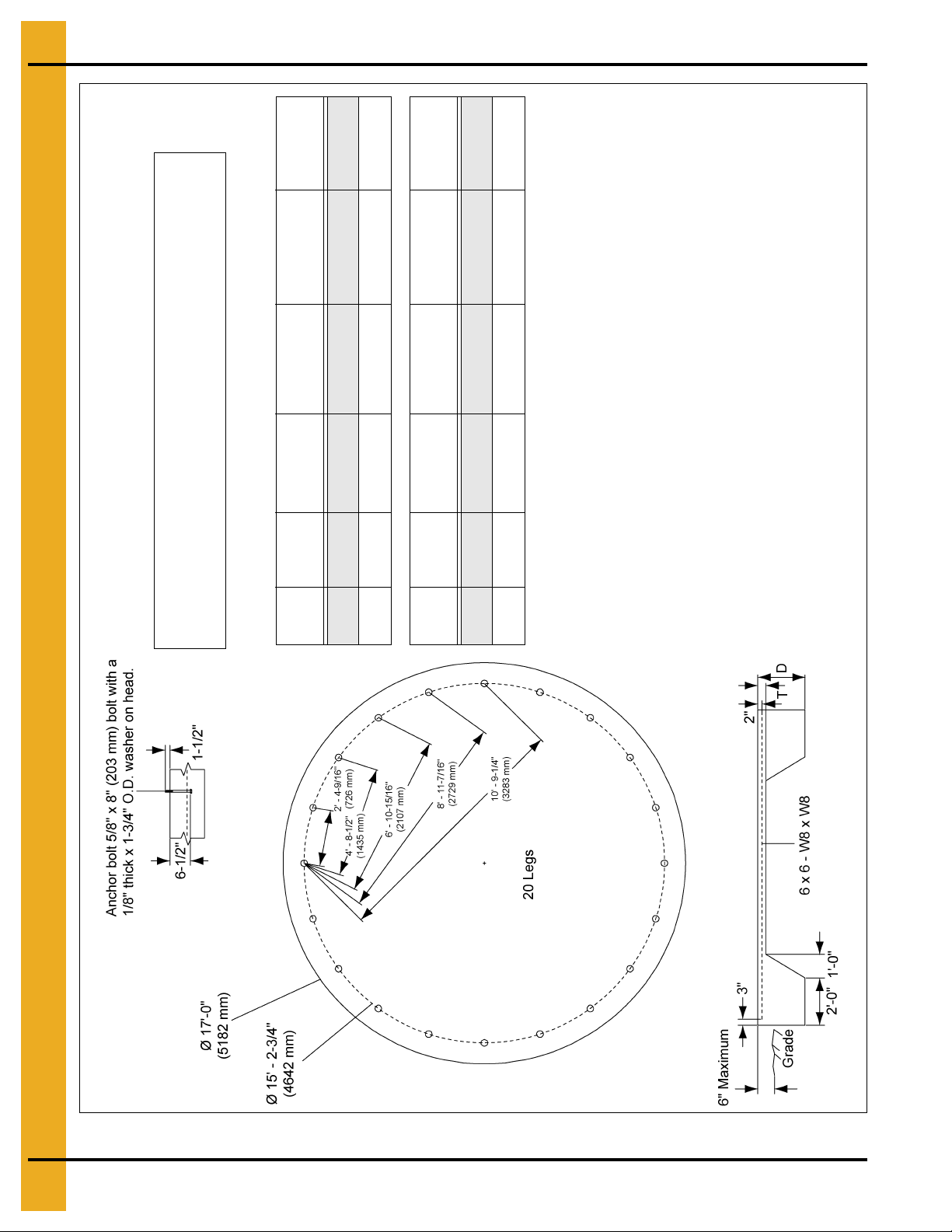
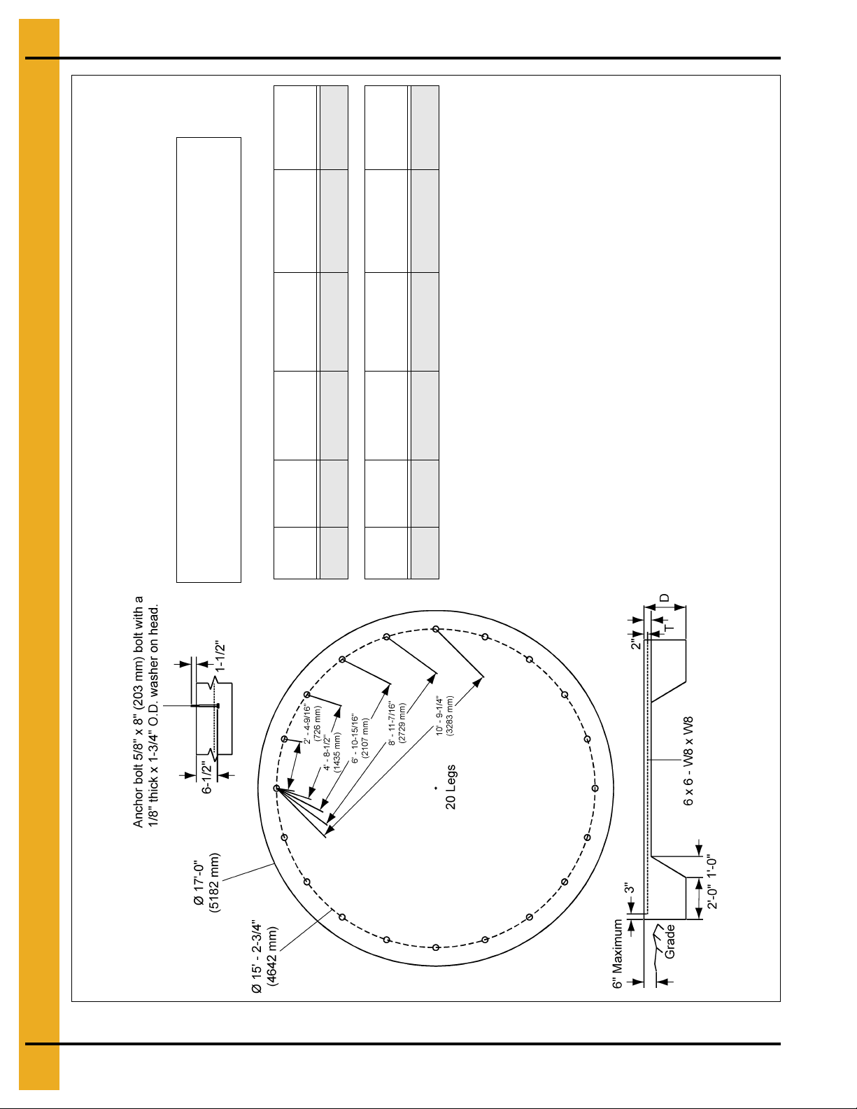
5. Foundation
# of
Rings
Footing
Depth (D)
Slab
Thickness (T)
Concrete
Volume
Wire Mesh
Area
# of Column
Legs
7 14" 4" 6.3 Cu. Yards 225 Sq. Ft. 20
8 15" 4" 6.6 Cu. Yards 225 Sq. Ft. 20
# of
Rings
Footing
Depth (D)
Slab
Thickness (T)
Concrete
Volume
Wire Mesh
Area
# of Column
Legs
7 356 mm 102 mm 4.82 Cu. Meters 20.9 Sq. Meters 20
8 381 mm 102 mm 5.05 Cu. Meters 20.9 Sq. Meters 20
GENERAL NOTES:
1. Foundation recommendations are based on 3500 lbs./ft.^2 allowable
soil bearing capacity.
2. Foundation recommendations are based on a minimum compressive
strength of 3000 PSI at 28 days.
3. The foundation site must be free of vegetation and debris and
well drained.
4. The foundation should be level within 1/4" overall and within
± 1/8" in any 10 ft. length along the anchor bolt circle.
5. Material estimates do not include allowance for shrinkage and waste.
6. These layouts are recommendations for GSI tanks only. Consult GSI
engineering for special tank foundations.
All instructions shall be construed as recommendations only. Because the
actual installation may vary according to local conditions. The GSI Group
assumes no liability for results arising from the use of such recommendations.
Figure 5F 15' 7-8 Rings BFT/GHT 60° Round Pad
20 PNEG-257 12', 15', 18' and 21' Bulk Feed Tanks BFT and GHT Series
Page 21
5. Foundation
# of
Rings
Footing
Depth (D)
Slab
Thickness (T)
Concrete
Volume
Wire Mesh
Area
# of Column
Legs
7 17" 4" 7.4 Cu. Yards 225 Sq. Ft. 15
8 18" 4" 7.7 Cu. Yards 225 Sq. Ft. 15
# of
Rings
Footing
Depth (D)
Slab
Thickness (T)
Concrete
Volume
Wire Mesh
Area
# of Column
Legs
7 432 mm 102 mm 5.66 Cu. Meters 20.90 Sq. Meters 15
8 457 mm 102 mm 5.89 Cu. Meters 20.90 Sq. Meters 15
GENERAL NOTES:
1. Foundation recommendations are based on 3500 lbs./ft.^2 allowable
soil bearing capacity.
2. Foundation recommendations are based on a minimum compressive
strength of 3000 PSI at 28 days.
3. The foundation site must be free of vegetation and debris and
well drained.
4. The foundation should be level within 1/4" overall and within
± 1/8" in any 10 ft. length along the anchor bolt circle.
5. Material estimates do not include allowance for shrinkage and waste.
6. These layouts are recommendations for GSI tanks only. Consult GSI
engineering for special tank foundations.
All instructions shall be construed as recommendations only. Because the
actual installation may vary according to local conditions. The GSI Group
assumes no liability for results arising from the use of such recommendations.
Figure 5G 15' 7-8 Rings BFT/GHT 45° Hopper Tank
PNEG-257 12', 15', 18' and 21' Bulk Feed Tanks BFT and GHT Series 21
Page 22
5. Foundation
# of
Rings
Footing
Depth (D)
Slab
Thickness (T)
Concrete
Volume
Wire Mesh
Area
# of Column
Legs
9 18" 4" 7.7 Cu. Yards 225 Sq. Ft. 20
# of
Rings
Footing
Depth (D)
Slab
Thickness (T)
Concrete
Volume
Wire Mesh
Area
# of Column
Legs
9 457 mm 102 mm 5.89 Cu. Meters 20.90 Sq. Meters 20
GENERAL NOTES:
1. Foundation recommendations are based on 3500 lbs./ft.^2 allowable
soil bearing capacity.
2. Foundation recommendations are based on a minimum compressive
strength of 3000 PSI at 28 days.
3. The foundation site must be free of vegetation and debris and
well drained.
4. The foundation should be level within 1/4" overall and within
± 1/8" in any 10 ft. length along the anchor bolt circle.
5. Material estimates do not include allowance for shrinkage and waste.
6. These layouts are recommendations for GSI tanks only. Consult GSI
engineering for special tank foundations.
All instructions shall be construed as recommendations only. Because the
actual installation may vary according to local conditions. The GSI Group
assumes no liability for results arising from the use of such recommendations.
Figure 5H 15' 9 Rings BFT/GHT 20 Leg 45° Tank
22 PNEG-257 12', 15', 18' and 21' Bulk Feed Tanks BFT and GHT Series
Page 23
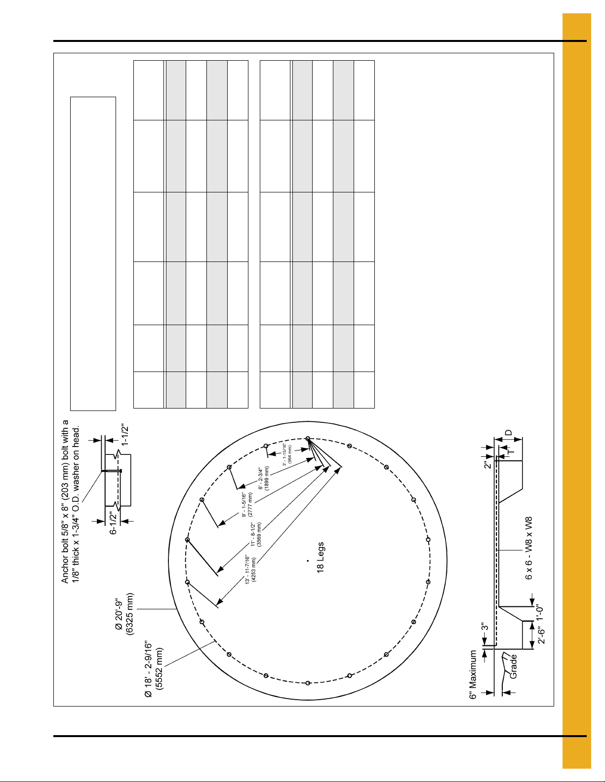
5. Foundation
# of
Rings
Footing
Depth (D)
Slab
Thickness (T)
Concrete
Volume
Wire Mesh
Area
# of Column
Legs
2-4 12" 4" 8.5 Cu. Yards 350 Sq. Ft. 18
5-6 15" 4" 10 Cu. Yards 350 Sq. Ft. 18
7 16" 4" 10.9 Cu. Yards 350 Sq. Ft. 18
8 18" 4" 11.5 Cu. Yards 350 Sq. Ft. 18
# of
Rings
Footing
Depth (D)
Slab
Thickness (T)
Concrete
Volume
Wire Mesh
Area
# of Column
Legs
2-4 305 mm 102 mm 6.5 Cu. Meters 32.52 Sq. Meters 18
5-6 381 mm 102 mm 7.66 Cu. Meters 32.52 Sq. Meters 18
7 406 mm 102 mm 8.33 Cu. Meters 32.52 Sq. Meters 18
8 457 mm 102 mm 8.79 Cu. Meters 32.52 Sq. Meters 18
GENERAL NOTES:
1. Foundation recommendations are based on 3500 lbs./ft.^2 allowable
soil bearing capacity.
2. Foundation recommendations are based on a minimum compressive
strength of 3000 PSI at 28 days.
3. The foundation site must be free of vegetation and debris and
well drained.
4. The foundation should be level within 1/4" overall and within
± 1/8" in any 10 ft. length along the anchor bolt circle.
5. Material estimates do not include allowance for shrinkage and waste.
6. These layouts are recommendations for GSI tanks only. Consult GSI
engineering for special tank foundations.
All instructions shall be construed as recommendations only. Because the
actual installation may vary according to local conditions. The GSI Group
assumes no liability for results arising from the use of such recommendations.
Figure 5I 18' 2-8 Rings BFT/GHT Hopper Tank
PNEG-257 12', 15', 18' and 21' Bulk Feed Tanks BFT and GHT Series 23
Page 24
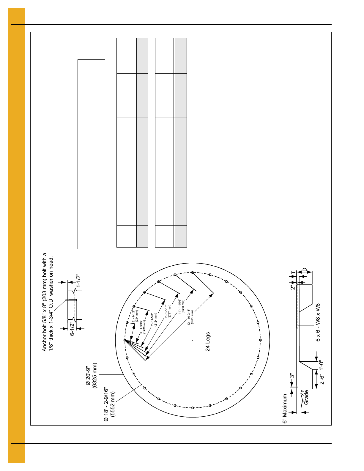
5. Foundation
# of
Rings
Footing
Depth (D)
Slab
Thickness (T)
Concrete
Volume
Wire Mesh
Area
# of Column
Legs
9 18" 4" 11.5 Cu. Yards 350 Sq. Ft. 24
# of
Rings
Footing
Depth (D)
Slab
Thickness (T)
Concrete
Volume
Wire Mesh
Area
# of Column
Legs
9 457 mm 102 mm 8.79 Cu. Meters 32.52 Sq. Meters 24
GENERAL NOTES:
1. Foundation recommendations are based on 3500 lbs./ft.^2 allowable
soil bearing capacity.
2. Foundation recommendations are based on a minimum compressive
strength of 3000 PSI at 28 days.
3. The foundation site must be free of vegetation and debris and
well drained.
4. The foundation should be level within 1/4" overall and within
± 1/8" in any 10 ft. length along the anchor bolt circle.
5. Material estimates do not include allowance for shrinkage and waste.
6. These layouts are recommendations for GSI tanks only. Consult GSI
engineering for special tank foundations.
All instructions shall be construed as recommendations only. Because the
actual installation may vary according to local conditions. The GSI Group
assumes no liability for results arising from the use of such recommendations.
Figure 5J 18' 9 Rings BFT/GHT 24 Leg Hopper Tank
24 PNEG-257 12', 15', 18' and 21' Bulk Feed Tanks BFT and GHT Series
Page 25
5. Foundation
# of
Rings
Footing
Depth (D)
Slab
Thickness (T)
Concrete
Volume
Wire Mesh
Area
# of Column
Legs
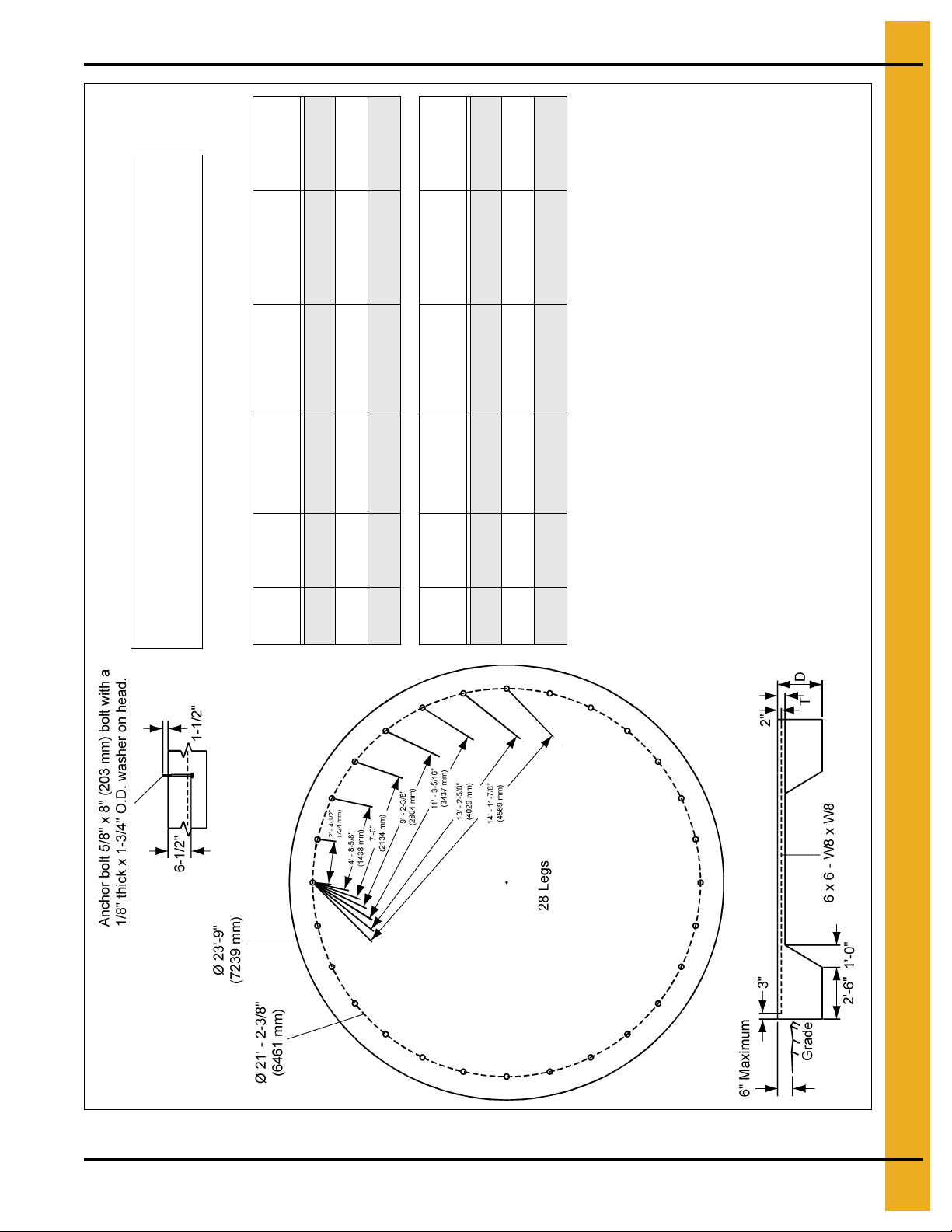
2-6 13" 4" 11 Cu. Yards 450 Sq. Ft. 28
7 15" 4" 12.1 Cu. Yards 450 Sq. Ft. 28
8 16" 4" 12.7 Cu. Yards 450 Sq. Ft. 28
# of
Rings
Footing
Depth (D)
Slab
Thickness (T)
Concrete
Volume
Wire Mesh
Area
# of Column
Legs
2-6 330 mm 102 mm 8.41 Cu. Meters 41.81 Sq. Meters 28
7 381 mm 102 mm 9.25 Cu. Meters 41.81 Sq. Meters 28
8 406 mm 102 mm 9.71 Cu. Meters 41.81 Sq. Meters 28
GENERAL NOTES:
1. Foundation recommendations are based on 3500 lbs./ft.^2 allowable
soil bearing capacity.
2. Foundation recommendations are based on a minimum compressive
strength of 3000 PSI at 28 days.
3. The foundation site must be free of vegetation and debris and
well drained.
4. The foundation should be level within 1/4" overall and within
± 1/8" in any 10 ft. length along the anchor bolt circle.
5. Material estimates do not include allowance for shrinkage and waste.
6. These layouts are recommendations for GSI tanks only. Consult GSI
engineering for special tank foundations.
All instructions shall be construed as recommendations only . Because the
actual installation may vary according to local conditions. The GSI Group
assumes no liability for results arising from the use of such recommendations.
Figure 5K 21' 2-8 Rings BFT/GHT 24 Hopper Tank
PNEG-257 12', 15', 18' and 21' Bulk Feed Tanks BFT and GHT Series 25
Page 26
6. Sidewall Assembly
Bulk Feed Tank Assembly
Model Gauge
BFT 12'-1 Ring 18
BFT 12'-2 Ring 13-20
BFT 12'-3 Ring 13-20-20
BFT 12'-4 Ring 13-18-20-20
BFT 12'-5 Ring 12-16-18-20-20
BFT 12'-6 Ring 12-15-16-18-20-20
BFT 12'-7 Ring 12-13-15-16-18-20-20
BFT 15'-2 Ring 14-16
BFT 15'-3 Ring 14-16-20
BFT 15'-4 Ring 14-16-18-20
BFT 15'-5 Ring 12-14-16-18-20
Body Sheet Chart
BFT 15'-6 Ring 12-14-16-16-18-20
BFT 15'-7 Ring 12-14-14-16-16-18-20
BFT 15'-8 Ring 12-14-14-14-16-16-18-20
BFT 18'-2 Ring 10-16
BFT 18'-3 Ring 10-16-20
BFT 18'-4 Ring 10-16-18-20
BFT 18'-5 Ring 10-16-18-20-20
BFT 18'-6 Ring 10-14-16-18-20-20
BFT 18'-7 Ring 10-14-16-18-18-20-20
BFT 18'-8 Ring 10-14-14-16-18-18-20-20
BFT 21'-2 Ring 10-16
BFT 21'-3 Ring 10-16-20
BFT 21'-4 Ring 10-16-20-20
BFT 21'-5 Ring 10-16-17-20-20
BFT 21'-6 Ring 10-16-17-17-20-20
NOTE: *Represents 45° Bulk Tanks. All other tanks come with 60° or 45° hoppers.
26 PNEG-257 12', 15', 18' and 21' Bulk Feed Tanks BFT and GHT Series
Page 27
6. Sidewall Assembly
How to use charts on this page:
The chart titled “body sheet chart” is for the reference when building the tank. This chart tells you how
many rings the specific tank must have. To read the chart you look up the tank size you wish to build
(an 18' diameter tank with 4 rings will look like BFT 18'-4 rings). The side labeled “gauge” will tell you which
body sheets to use. The sheets are color coded, all t hat needs to be done is to match the gaug e number
with the color. (Use sheet gauge color code chart.)
IMPORTANT: Number of rings shown for each tank size are maximums. (12' 60° Tanks have a 6 ring
maximum. 15' 45° and 18' 45° tanks have an 8 ring maximum.)
NOTE: Body sheets are color coded on edges for gauge identification.
Sheet Gauge Color Code Chart
Code # Color Code
20 Red
18 Orange
17 Pink/Light Blue
16 Blue
15 Brown/Red
14 Green
13 Yellow/Blue
12 Black
11 Pink
10 Light Blue
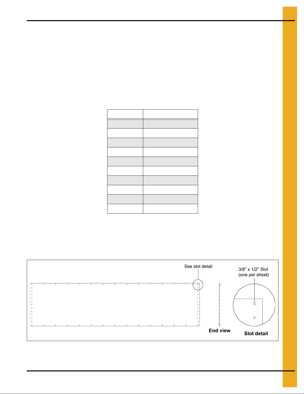
Sidewall Sheet Orientation (12' Only)
IMPORTANT: Please note the sheet orientation when assembling the bin sidewall. The upper right
corner will have a slot or identifying sticker. This corner should be on the inside of the tank
when assembled.
Figure 6A Viewed from Inside
Sheet orientation will effect how the sheets lap together.
PNEG-257 12', 15', 18' and 21' Bulk Feed Tanks BFT and GHT Series 27
Page 28
6. Sidewall Assembly
Sidewall Erection
12'-21' Bulk Feed Tank
12'-21' Diameter Bulk Feed Tanks are designed to be built vertically utilizing bin jacks or a crane of
adequate capacity. Before bolting the sidewall sheets together, check that you have the proper gauge
steel for the first ring. The higher gauge number denote the thinner materials. (Example, 2 0 gauge material
is thinner than 14 gauge.) In erecting all bulk feed tanks the thinnest material always goes on top, therefore
the first sidewall ring you assemble will be the top ring of the tank. Check the various gauges of the tank
with the color code chart and begin building accordingly. Remember, assemb le the top ring first. Note ring
overlap detail as shown in Figure 6B.
NOTE: See Page 27 for proper gauges and color code chart.
IMPORTANT: The number of rings shown for each tank size are maximums. (21' 45° and 15 ' 60 ° tanks
have a 6 ring maximum. 12' 60° tanks have a 7 ring maximum. The 12' 45°, 15' 45° and
18' 45° tanks have an 8 ring maximum.)
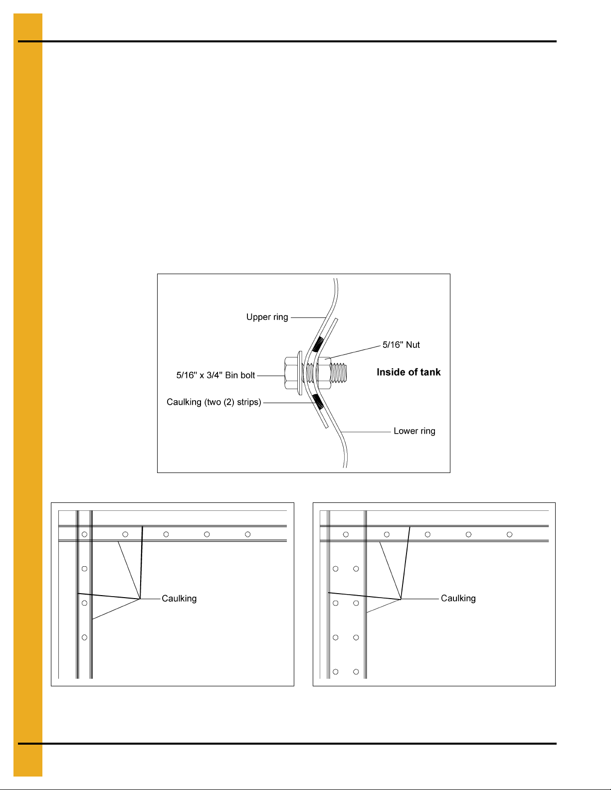
Figure 6B Ring Overlap Detail
Figure 6C Caulking Detail (For 12' tanks only.) Figure 6D Caulking Detail (For 15', 18' and 21' tanks.)
28 PNEG-257 12', 15', 18' and 21' Bulk Feed Tanks BFT and GHT Series
Page 29

6. Sidewall Assembly
Figure 6E
Figure 6F
IMPORTANT: BOLTING PATTERN BEGINS IN THE CENTER OF THE SHEET. When starting to
assemble the sidewall rings to one another. Be sure to start in the center of the sheets
and work to the outside edges (horizontal seams). This allows the sidewall sheets to draw
up evenly.
Figure 6G
Once you have selected the proper gauge material, begin assembling all sidewall sheets in the following
manner: Standing on the inside of the tank, place the left panel to the inside with the right panel to
the outside.
NOTE: The rope caulking is installed before each sheet is assembled. Wip e sheets clean where caulking
is to be applied. Apply caulking on each side of the holes in the vertical seams and also on each
side of the horizontal row of holes.
Using correct size bin bolt throughout, begin assembling sidewall sheet end to end (overlapping the same
way throughout) until the ring is completed. All body sheet bolts are to be installed with the bolt head and
its neoprene washer to the outside and the nut to the inside. Do not tighten bolts until all sheets are
assembled and form a complete ring. Remember to attach lifting straps at the bottom of the vertical seams
while bolting the sheets together. These straps, coupled to the jacks, will enable you to later elevate the
tank. Now tighten the bolts, in sequence, starting from the center and working to the edge in both
directions. This permits the sidewall sheets to draw-up evenly. Complete one ring and stop. You are now
ready to assemble the roof.
PNEG-257 12', 15', 18' and 21' Bulk Feed Tanks BFT and GHT Series 29
Page 30
7. Roof
Sealed Roof Panel Installation (12'-18' BFT)
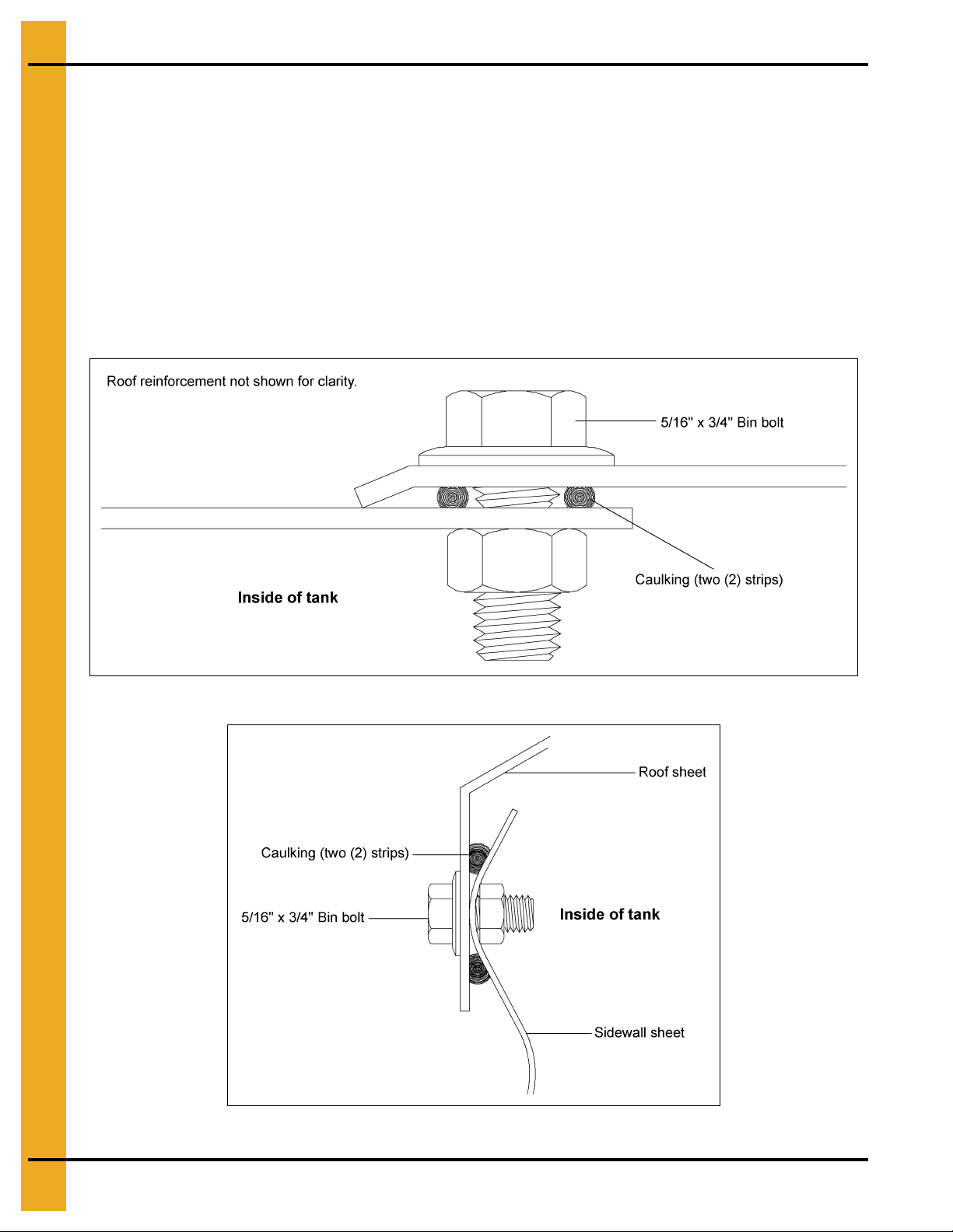
Roof to Sidewall
Note that the roof and sidewall ladders are centered on a roof seam. Take notice when placing roof panel,
that one edge is bent down. This edge is to be placed on the outside of other roof panel to form a tight
seal. Be sure to apply two (2) strips of caulking on all seams.
Roof Assembly
Assemble roof panels in a counterclockwise manner. On bins that will be equipped with pnuematic fill
system (See Page 68), the two (2) roof panels with fill hole and exha ust ho le sh ould be located opposite
each other on Bulk Feed Tank.
Figure 7A Roof Sheet Overlap Detail
Figure 7B Eave Detail
30 PNEG-257 12', 15', 18' and 21' Bulk Feed Tanks BFT and GHT Series
Page 31

7. Roof
Caulking
Peak ring
Caulking
Peak Ring
The peak ring may now be installed. Again use two (2) strips of caulking between peak ring and roof
panels. (See Figure 7C.) Note that the peak ring goes to the outside of the roof panels.
Figure 7C
Figure 7D
PNEG-257 12', 15', 18' and 21' Bulk Feed Tanks BFT and GHT Series 31
Page 32

7. Roof
Peak Ring Collar Detail
12' Roof Reinforcement Angle
Figure 7E
Figure 7F
32 PNEG-257 12', 15', 18' and 21' Bulk Feed Tanks BFT and GHT Series
Page 33

Roof Ladder
NOTE: Make sure ladder is positioned so it will fall between the legs when tank is complete.
NOTE: Ladder is symmetrical about roof seam. One side shown for clarity.
7. Roof
Figure 7G
Roof Ladder Parts List
Ref # Part # Description
1 BLK-11680 Ladder Eave Safety Ring 2 2 2
2 BLK-11762 12' BFT Roof Ladder Support Channel 2 - 2 BLK-11763 15' BFT Roof Ladder Support Channel - 2 2 BLK-11764 18' BFT Roof Ladder Support Channel - - 2
3 S-275 5/16'' x 3/4'' Bin Bolt 20 22 24
4 BLK-11679 Roof Ladder Rung 4 5 6
5 S-396 5/16''-18 Hex Nut 20 22 24
6 BLK-11673 Lower Support Channel Bracket 2 2 2
7 LDR-4002 44'' (1118 mm) Sidewall Ladder Bracket - - 8 LS-121 Sidewall Ladder Standoff - - -
Qty
12' Diameter
PNEG-257 12', 15', 18' and 21' Bulk Feed Tanks BFT and GHT Series 33
Qty
15' Diameter
Qty
18' Diameter
Page 34

7. Roof
Figure 7H
Figure 7I Roof Ladder Peak Ring Detail
34 PNEG-257 12', 15', 18' and 21' Bulk Feed Tanks BFT and GHT Series
Page 35

7. Roof
Figure 7J
Roof Ladder Parts List
Ref # Part # Description
1 LS-147 Inside Ladder Standoff 2 2 2
2 BLK-11762 12' BFT Roof Ladder Support Channel 2 - 2 BLK-11763 15' BFT Roof Ladder Support Channel - 2 3 BLK-11764 18' BFT Roof Ladder Support Channel - - 2
4 S-275 5/16'' x 3/4" Bin Bolt 20 22 24
5 BLK-11679 Roof Ladder Rung 4 5 6
6 S-396 5/16''-18 Hex Nut 20 22 24
7 BLK-11872 Center Roof Ladder Support 1 2 2
8 BLK-11873 Outer Ladder Support 2 4 4
Qty
12' Diameter
Qty
15' Diameter
Qty
18' Diameter
NOTE: Three (3) holes spaces on either side of centerline of ladder. (Six (6) spaces between brackets.)
NOTE: Center roof ladder over roof seam during assembly. Ladder is symmetrical about roof seam. One
side shown for clarity. Use 5/16" bin bolts and nuts for assembly. Position ref# 6 and ref# 7 as
needed for additional support.
PNEG-257 12', 15', 18' and 21' Bulk Feed Tanks BFT and GHT Series 35
Page 36

7. Roof
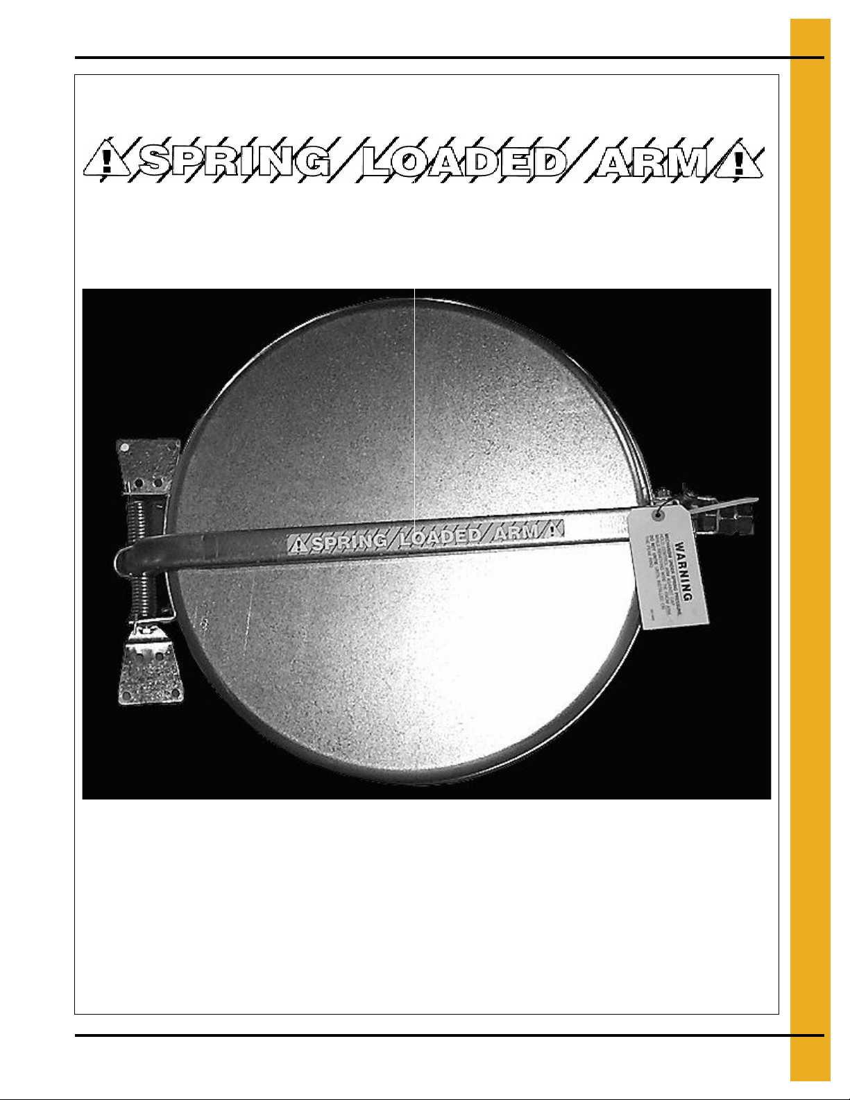
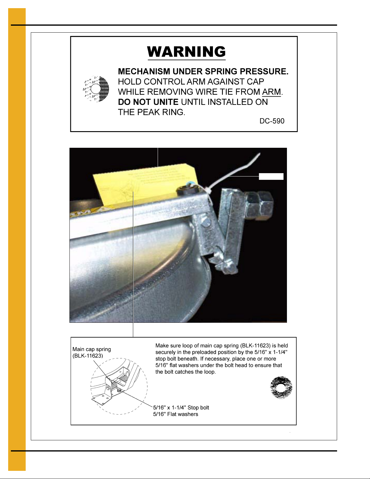
The control arm is spring loaded. Be careful when removing shipping retainers.
See Figure 7P on Page 38
See Figure 7Q on Page 38
(See Figure 7L.)
12' 60° Roof Cap Ground Control
Ground control comes standard on 12' 60° Bulk Feed Tanks. Ground control is optional on all 45° Bulk
Feed Tanks. Ground control components come fully assembled for the convenience. The ground control
is shipped with the arm secured for safety and shipping purposes. The wire and retaining tie are intended
for shipping use only.
CAUTION
Refer to control arm and ground control details on Page 40 for component part assembly. The peak cap
latch hook, located opposite the cap hinge, latches over the cap hold-down bracket. (Ref# 20, ground
control detail on Page 40). One end of the ground control chain is secured at the counterweight arm
with a cotter pin. (See Figure 7L.) The chain is passed up and over the cap, through the grommet on the
pivot arm and through the roof eave bracket (BLK-11950), then continues down the side of the tank.
Figure 7K
Figure 7L
36 PNEG-257 12', 15', 18' and 21' Bulk Feed Tanks BFT and GHT Series
Page 37

7. Roof
Chain passes
through grommet
Peak cap latch
Cap hold-down
bracket
1
2
3
4
5
6
7
8
1 - Chain holder (BLK-11949)
2 - Cap hold-down bracket
3 - Roof eave bracket (BLK-11950)
4 - 5/16" Bolt
5 - 5/16" Flat washers
6 - Cotter pin
7 - Key ring clips
8 - 4" Plastic handles (2)
Figure 7M
Figure 7N
PNEG-257 12', 15', 18' and 21' Bulk Feed Tanks BFT and GHT Series 37
Figure 7O
Page 38

7. Roof
Roof eave bracket
(BLK-11950)
Chain holder
(BLK-11949)
Handle
Key ring
Figure 7P
After removing the slack from the ground control chain while in the fully closed and latched position. Install
the key ring clip 2" below chain holder bracket. (See Figure 7Q.) Ensure that the key ring allows the cap
to fully latch when the cap is in the closed position, ye t will not allow the chain enough slack on to p of the
cap to become wrapped around the pivot arm in a high wind condition.
Bolt the chain holder (BLK-11949) to the bottom horizontal row of sidewall holes or field drill and bolt to
the leg tie brace. (See Figure 7Q.) Two (2) 4" plastic handles and extra key ring clips are provided for use
at the hopper eave to be used as fully open and fully closed cap indicators.
Figure 7Q
38 PNEG-257 12', 15', 18' and 21' Bulk Feed Tanks BFT and GHT Series
Page 39

Figure 7R
Make sure the loop of the main cap spring (BLK-11623) is held securely
in the pre-loaded position by the head of the 5/16" bolt beneath.
If necessary, place one or more 5/16" flat washers under the bolt head to ensure that the bolt
catches the loop.
The control arm is spring loaded. It must be released while on the ground and
before attaching it to the peak ring. Failure to do so will result in serious injury.
7. Roof
Figure 7S
WARNING
PNEG-257 12', 15', 18' and 21' Bulk Feed Tanks BFT and GHT Series 39
Page 40

7. Roof
Figure 7T
Control Arm and Ground Control Parts List
Ref # Part # Description
1 BLK-11735 Control Arm
2 BLK-11876 Nylon Grommet with Nut
3 BLK-11623 Flush Cap Main Spring
4 S-277 5/16''-18 x 1-1/4" Bin Bolt (Grade 5)
5 S-845 5/16'' Wrought Iron Washer (Grade 2)
6 BLK-11842 Lower Cap Hinge
7 BLK-11734 Upper Cap Hinge
8 S-7329 5/16''-18 x 2'' Hex Head Bolt
9 BLK-10015 Bulk Tank Roof Cap
10 S-5220 5/16''-18 Hex Lock Nut (Grade 2)
11 BLK-11503 1-7/8'' Long Spring Spacer
12 BLK-11730 1 Piece Bulk Tank Peak Ring
13 S-7171 3/8''-16 x 6-1/2" Hex Head Bolt (Grade 5)
14 S-3214 7/8''-9 Hex Nut (Grade 2)
15 BLK-11845 Latch Counterweight
16 S-7281 7/8''-9 x 1-1/2" Hex Head Bolt
17 BLK-11844 Peak Cap Latch
18 BLK-11795 15/16'' x 3/4" Diameter Plastic Spacer
19 BLK-11843 Pivot Bracket
20 BLK-11846 Cap Hold-Down Bracket
21 S-4663 3/8''-16 Hex Head Lock Nut
NOTE: Use the above chart for control arm and ground control details.
40 PNEG-257 12', 15', 18' and 21' Bulk Feed Tanks BFT and GHT Series
Page 41

Roof Cap
Bulb seal
(BLK-10472)
Bulb Seal Kit (Optional)
Cap Hold-Down Package
7. Roof
Figure 7U
Figure 7V
Bulb seal is pressed into place around the lip of the peak ring.
NOTE: Bulb seal kit is included with all pneumatic fill kits. When ordered as a separate option, specify
part# BLK-10472.
Cap hold-down package comes standard on all 45° hopper bulk tanks. Optional on all 60° hopper
bulk tanks.
PNEG-257 12', 15', 18' and 21' Bulk Feed Tanks BFT and GHT Series 41
Page 42

7. Roof
15' and 18' Roof Assembly Instructions
After completing first ring assembly, you are ready to begin roof construction. First, build a roof center
support to hold the peak ring in place at the proper height. A simple structure consisting of a sturdy cross
arm attached to a pole and supported by a platform or scaffolding will do. Stand the center support directly
in the center of the tank. The bottom of the peak ring should be 89-5/16" (2269 mm) above the foundation
on the 18' tank and 78-15/16" (2005 mm) above it on the 15' tank. These dimensions are approximate
ones used in BFT construction. Adjusting the center support height will ease roof erection. Refer to
accompanying drawings for details. Install six (6) roof reinforcement angles spaced equally around the
tank. Reinforcement angle edges are parallel with sidewall sheet and peak ring, see views “AA” and “DD”
on Page 43.
The reinforcement angles utilize every other hole in the peak ring. At the sidewall, there are twelve (12)
spaces between each reinforcement angle on the 18' tank and ten (10) spaces between each on the
15' tank. Next, “skin” the roof by installing the roof panels on the just completed reinforcement structure.
Reinforcement angles will share all roof panels holes, including hole where pane l and pea k ring attach.
Ensure that all roof seams are caulked and lapped correctly as shown in the accompanying detail drawings.
Figure 7W
42 PNEG-257 12', 15', 18' and 21' Bulk Feed Tanks BFT and GHT Series
Page 43

7. Roof
Figure 7X View “A”-“A”
Figure 7Z View “C”-“C”
Figure 7Y View “B”-“B”
PNEG-257 12', 15', 18' and 21' Bulk Feed Tanks BFT and GHT Series 43
Figure 7AA View “D”-“D”
Page 44

7. Roof
Raising the Roof
NOTE: See 30° roof manual (PNEG-1092) in roof hardware box for instructions on 12', 15', 18' and
21' grain bin roof.
Figure 7AB
Anchor Tank Before 2ndRing Assembly
Anchor all jacks securely with metal stakes and cables (use one jack per sidewall sheet). Now raise the
tank just enough to assemble the next ring. When lifting the tank crank all jacks at an equal rate. This will
prevent bowing previously assembled rings and make for easier hole alignment. To the inside of the first
ring bolt the next ring. Be sure to stagger the sheets and select the proper gaug e material. Lower the tank
on the foundation after assembling and tightening bolts on each new ring. Now re-bolt lifting straps t o the
lowest ring in place thus far.
NOTE: Add outside ladders and other accessories to tank walls as you continue to raise the tank.
After body sheets are assembled and bolts are tightened, raise the tank and attach the legs. Do not put a
bolt in the bottom sidewall hole yet, because the hopper must be attached here. When the legs are in place
and tightened, release the jack enough to rest the tank on the legs.
44 PNEG-257 12', 15', 18' and 21' Bulk Feed Tanks BFT and GHT Series
Page 45

7. Roof
Watch for power lines.
The crane and anything associated with building the bin (due to height) can get
in the way of power lines.
Figure 7AC
A crane of adequate capacity attached to a spider assembly with cables connecting at each vertical
sidewall seam just above the legs can also be used to lift the tank. Make sure the tank is being lifted
smoothly and evenly. Raise it enough to assemble the next ring and/or to attach the legs. Reference a
qualified rigger.
WARNING
12' 60° and 15' 60° Leg Attachment (for 12' 60° and 15' 60° Tanks Only)
Curved washer are supplied in the hardware packages. These washers must be installed at the bottom
leg to sidewall bolt connection, to the inside of the hopper panel as indicated in Figure 7AD. Apply caulking
in between the hopper panel and the sidewall sheet.
Figure 7AD
PNEG-257 12', 15', 18' and 21' Bulk Feed Tanks BFT and GHT Series 45
Page 46

8. Hopper Assembly
Hopper Sheets
When starting to attach hopper sheets to sidewall it is recommened that the first hopper sheet seam be
positioned halfway between leg positions. Lap the hopper sheets as shown in Figure 8D and Figure 8G
on Page 48. Use two (2) strips of caulking on all seams at sidewall to hopper and hopper sheet to hopper
sheet. Use 5/16" x 1-1/4" bin bolts (head to outside of tank) for att aching hopper sheets to bottom sidewall
sheet. Use truss head bolts to attach hopper sheet to hopper sheet. Be sure to place the head of the truss
head bolt on the inside of the hopper. Leave one hopper sheet out to allow room to install the hopper collar.
Be sure to use two (2) strips of caulking between hopper collar and hopper sheets, then put last hopper
sheet in place. After the collar is in place, attach the hopper braces and tighten all bolts.
Figure 8A
15' 60°, 18' 45° and 21' 45°
Install hopper sections. When starting to attach hopper sheets to sidewall it is recommended that the
first hopper sheet seam be positioned halfway between leg positions. Lap the hopper sheets as shown
in Figure 8B and Figure 8C on Page 47. Use 5/16" x 1-1/4" bin bolts (head to out side of tank) for attaching
hopper sheets to bottom sidewall sheet. Use truss head bolts to attach hopper sheet to hopper sheet.
Be sure to place the head of the truss head bolt on the inside of the hopper. Caulk all seams (double bead).
Remember, the hopper collar must be installed before the last hopper section is in place. Clean any
caulking, which may have squeezed out during assembly, off the inside of the hopper. After the collar
is in place, attach the hopper braces and tighten all bolts.
46 PNEG-257 12', 15', 18' and 21' Bulk Feed Tanks BFT and GHT Series
Page 47

8. Hopper Assembly
Figure 8B 15' 60° Two-Piece Hopper Overhead View of 15' 60° Hopper Sheet Assembly
Figure 8C 18' and 21' Two-Piece Hopper Overhead View of 18' 45° and 21' 45° Hopper Sheet Assembly
PNEG-257 12', 15', 18' and 21' Bulk Feed Tanks BFT and GHT Series 47
Page 48

8. Hopper Assembly
Figure 8D 15' 60°, 18' 45° and 21' 45°
Hopper Sheet Detail
Figure 8F 22" Hopper Collar Detail
Figure 8E 16" Hopper Extension Detail
Figure 8G 16" Hopper Collar Detail
NOTE: EVERY HOLE IN HOPPER SHEET WILL BE UTILIZED. Use 5/16" x 3/4" truss head bolt on
hopper seams. (Truss head goes on inside of hopper.)
48 PNEG-257 12', 15', 18' and 21' Bulk Feed Tanks BFT and GHT Series
Page 49

8. Hopper Assembly
Hopper Collar Assembly
45° 22" Hopper collar (BLK-10854)
60° 22" Hopper collar (BLK-10342)
Install hopper collar before all hopper panels are assembled. Use 5/16" truss head bolts, as shown
in Figure 8H, on all hopper seams. Be sure to caulk between the hopper collar and hopper panels.
(See Figure 8I and Figure 8J.)
Figure 8H Hopper Seam Overlap Detail
16" 45° Hopper extension panel (BLK-10697) (three (3) required)
16" 45° Hopper collar (BLK-10696)
16" 60° Hopper extension panel (BLK-10487) (three (3) required)
16" 60° Hopper collar (BLK-10489)
Before last hopper panel is attached, assemble the hopper extensions (if utilized) on the hopper collar.
Use 5/16" truss head bolts and caulk all joints on the hopper extensions and collar. After completing this
assembly, attach to the hopper panels, using 5/16" truss head bolts. Be sure to caulk between hopper
extensions and hopper panels. (See Figure 8I and Figure 8J.)
Figure 8I 22" Hopper Collar
Figure 8J 16" Hopper Extensions and Collar
PNEG-257 12', 15', 18' and 21' Bulk Feed Tanks BFT and GHT Series 49
Page 50

9. Leg and Leg Bracing
12' Only
Figure 9A
Figure 9B
50 PNEG-257 12', 15', 18' and 21' Bulk Feed Tanks BFT and GHT Series
Figure 9C
Page 51

Installation of Leg to Sidewall
9. Leg and Leg Bracing
Figure 9D
Use 5/16" x 3/4" bin bolts and nuts when attaching the leg to base. Make sure the washer is used on the
slot side of the leg.
When installing legs to sidewall, reverse normal insertion procedure on bolts. Place hex head and
neoprene washer to inside of sidewall, leaving threaded portion of bolt protruding outward. This
provides for a weather-tight seal at the leg attachment location. (See leg size chart on Page 54 before
attaching legs.)
Figure 9E
PNEG-257 12', 15', 18' and 21' Bulk Feed Tanks BFT and GHT Series 51
Page 52

9. Leg and Leg Bracing
Installation of Leg to Sidewall for 15', 18' and 21' BFT
When installing legs to sidewall, reverse normal insertion procedure on bolts. Place hex head and
neoprene washer to inside of sidewall, leaving threaded portion of bolt protruding outward. This p rovides
for a weather-tight seal at the leg attachment location.
NOTE: Insert bolts from inside to outside on all leg to tank connections.
Figure 9F Plug Holes
Figure 9H Installing legs to bin with bolt heads on the
inside of bin and nuts on the outside.
Figure 9G
52 PNEG-257 12', 15', 18' and 21' Bulk Feed Tanks BFT and GHT Series
Page 53

9. Leg and Leg Bracing
“A”
“B”
12'-21' Leg Bracing
Tank “A” “B” “C” “D”
12' 60° 36.962" 66.962" 112.359"
12' 45° 66.962" 36.962"
15' 60° 50.596" 75.596" 138.250"
15' 45° 80.596" 50.596"
18' 45° 50.596" 63.640" 120.237"
21' 45° 55.075" 66.075" 133.075"
See Pages 55-58 for attachment points of bracing. Use 3/8" nuts and bolts to attach cross ties to each
other and to leg. Hopper braces are attached to legs with 3/8" nuts and bolts and to hopper collar with
5/16" hardware. Ladder standoffs are attached to legs with 5/16" nuts and bolts. See Figure 9I below and
Figure 9J on Page 54 show typical bracing attachment points to the leg. Do not tighten any hardware until
all bracing is in place. See chart above for dimensions called out as shown in Figure 9I below and Figure
9J on Page 54.
Figure 9I Typical 12' and 15' 45° Bracing Layout
PNEG-257 12', 15', 18' and 21' Bulk Feed Tanks BFT and GHT Series 53
Page 54

9. Leg and Leg Bracing
Figure 9J Typical 18' and 21' 45° and 12' and 15' 60° Bracing Layout
Leg Size Chart
Tank Size Hopper # of Rings Length
12' Diameter Tank 45° 1-5 Rings 130-1/8''
12' Diameter Tank 45° 6-7 Rings 154-1/8''
12' Diameter Tank 60° 1-5 Rings 175-1/8''
12' Diameter Tank 60° 6-7 Rings 199-1/8''
15' Diameter Tank 45° 2-8 Rings 172-3/8''
15' Diameter Tank 60° 2-6 Rings 231"
18' Diameter Tank 45° 2-8 Rings 190-1/4''
21' Diameter Tank 45° 2-6 Rings 201-1/2''
Depending on the size of the Bulk Feed Tank you are asse mbling, the leg will cover either the bottom ring
or 1-3/4 rings (56"). Refer to above chart to find the correct number of rings the legs will cover. Put all
legs on, but do not tighten bolts until all braces are in place. Be sure to put leg braces on properly.
(See Pages 55-58.)
54 PNEG-257 12', 15', 18' and 21' Bulk Feed Tanks BFT and GHT Series
Page 55

Bracing Hole Layouts
9. Leg and Leg Bracing
Figure 9K Figure 9L
PNEG-257 12', 15', 18' and 21' Bulk Feed Tanks BFT and GHT Series 55
Page 56

9. Leg and Leg Bracing
Bracing Hole Layouts (Continued)
Figure 9M
All leg to sidewall holes must be utilized for leg attachment.
56 PNEG-257 12', 15', 18' and 21' Bulk Feed Tanks BFT and GHT Series
Figure 9N
Page 57

Bracing Hole Layouts (Continued)
9. Leg and Leg Bracing
Figure 9O
All leg to sidewall holes (22 at 2.666" spacing) must be utilized for leg attachment.
PNEG-257 12', 15', 18' and 21' Bulk Feed Tanks BFT and GHT Series 57
Figure 9P
Page 58

9. Leg and Leg Bracing
Bracing Hole Layouts (Continued)
Figure 9Q
All leg to sidewall holes (22 at 2.666" spacing on 18'; 20 at 2.66" on 21') must be utilized for leg attachment.
58 PNEG-257 12', 15', 18' and 21' Bulk Feed Tanks BFT and GHT Series
Figure 9R
Page 59

9. Leg and Leg Bracing
Hopper to Leg Bracing
Hopper braces are to be spaced equally around tank. Hopper braces are required on all hopper tanks.
Refer to chart below for the quantities required.
NOTE: Hopper braces attach between the legs and the collar/hopper horizontal seam. Never bolt the
braces directly to the hopper seam above the collar.
Figure 9S
Description 16" Hopper Brace Part # 22" Hopper Brace Part # Qty
12' Diameter 45° Hopper BLK-12115 BLK-12116 8
12' Diameter 60° Hopper BLK-121 13 BLK-12114 8
15' Diameter 45° Hopper BLK-12118 BLK-12120 3
15' Diameter 60° Hopper BLK-121 17 BLK-12119 3
18' Diameter 45° Hopper BLK-12121 BLK-12122 3
21' Diameter 45° Hopper BLK-12123 BLK-12124 4
Directions: Locate correct tank in far left column, braces are located across top of chart. Follow the
column down to correct tank line and read the quantity required for that tank.
Cross Tie Brace Usage Chart
Description Inside Cross Tie Outside Cross Tie
12' Diameter 60° Hopper 16 16
12' Diameter 45° Hopper 8 8
15' Diameter 45° Hopper 15 15
15' Diameter 60° Hopper 30 30
18' Diameter 45° Hopper 36 36
21' Diameter 45° Hopper 56 56
PNEG-257 12', 15', 18' and 21' Bulk Feed Tanks BFT and GHT Series 59
Page 60

10. Ladder
Optional Sidewall Ladder
To start sidewall ladder, places two (2) outside standoffs spaces 18-3/4" apart. At the roof eave, the ladder
should be located on the standoffs. (See Figure 10A.) Continue with standoff located on every horizontal
seam. Ladder support ring should be located between two (2) legs as shown. This will standoff the ladder
at the bottom of Bulk Feed Tank. When positioning the ladder on the tank, be sure to attach ladder so the
raised non-slip tread surface is to the top of the ladder rungs.
Figure 10A Ladder St andoff Detail Figure 10B
Note locations of legs and other rings horizontal hole spacing when placing ladder.
Ladder Standoff Ring Chart
Tank Diameter Ladder Standoff Ring Part # Qty Required 45° Qty Required 60°
12' BLK-10150 3 3
15' BLK-11814 3 4
18' BLK-11814 3 21' BLK-11815 3 -
Figure 10C
60 PNEG-257 12', 15', 18' and 21' Bulk Feed Tanks BFT and GHT Series
Page 61

Ladder Safety Cage
Ladder and Safety Cage Usage Chart (Number in Chart Specifies Ring Size)
Ladder Package # Safety Cage # 12' 60° 12' 45° 15' 45° 18' 45°
BLK-10635 BLK-10833 - 2 - BLK-10825 BLK-10834 - - 2 2
BLK-10640 BLK-10835 2 3 3 BLK-10637 BLK-10836 - 4 - 3
BLK-10641 BLK-10837 3 5 4 4
BLK-10642 BLK-10838 4 - 5 BLK-10643 BLK-10839 5 6 - 5
BLK-10826 BLK-10840 - 7 6 BLK-10644 BLK-10841 6 - 7 6
BLK-10827 BLK-10842 - - - 7
BLK-10828 BLK-10843 - - 8 8
10. Ladder
Optional Safety Cage
Use 5/16" hex head bolts on all safety cage connections.
Figure 10D
PNEG-257 12', 15', 18' and 21' Bulk Feed Tanks BFT and GHT Series 61
Page 62

10. Ladder
Start attaching ladder at the eave (top) of the Bulk Feed Tank. After the first ladder has been attached to
the sidewall of tank, attach ladder extension rails to the ladder as shown in Figure 10F. Refer to Page 61
for proper ladder placement in relation to the eave of the tank. Use hex head bolts on all safety cage
connections. Attach hoop brackets and adjustable safety cage brace to the top of the extension rails.
Be sure to attach the adjustable brace on the left side of the ladder. Now attach the opposite end of the
adjustable brace to the roof ladder rail. After completing this, drill two (2) 5/16" holes through the adjustable
brace and use 1/4" x 1-1/2" bolts and nuts to secure the two (2) braces together.
Add the safety cage hoops to the brackets and attach vertical supports to the hoops. Continue adding
ladder sections and safety cage as sidewall rings are attached. Included in the safety cage package are
two (2) bell hoop halves (See Page 61) which should be located at the bottom of the safety cage. Follow
all drawings and details for proper placement of parts and proper location of safety cage.
Figure 10E Side View
Figure 10F Front View
62 PNEG-257 12', 15', 18' and 21' Bulk Feed Tanks BFT and GHT Series
Page 63

10. Ladder
Figure 10G
Safety Cage Assembly
Figure 10H
PNEG-257 12', 15', 18' and 21' Bulk Feed Tanks BFT and GHT Series 63
Page 64

10. Ladder
Figure 10I
Figure 10J
64 PNEG-257 12', 15', 18' and 21' Bulk Feed Tanks BFT and GHT Series
Page 65

11. Raising Bin
WARNING
Make sure there is enough clearance between the tank and surrounding power
lines, electricution may occur.
WARNING
All usual and customary precautions must be taken to ensure safety of personnel
and property.
Raising Bin to Set on Foundation
Be sure that all bolts are tightened properly. The Bulk Feed Tank can now be set up on foundation. A crane
of adequate capacity attached to a spider assembly with cables connecting at each vertical sidewall seam
just above the legs will usually do the job. Reference a qualified rigger.
Anchoring Tank
Check all legs to see if shims are necessary to level the tank properly (shims are to be obtained locally).
After Bulk Feed Tank is level and shimmed properly, anchor the tank down with 5/8" washers and nuts.
(See Figure 11A.)
Figure 11A Leg Base Detail
PNEG-257 12', 15', 18' and 21' Bulk Feed Tanks BFT and GHT Series 65
Page 66

11. Raising Bin
Figure 11B
NOTE: Leg shims are not standard equipment and must be obtained locally.
66 PNEG-257 12', 15', 18' and 21' Bulk Feed Tanks BFT and GHT Series
Page 67

12. Grounding
NOTE: Parts not supplied by manufacturer, they should be purchased locally.
All bins shall have two (2) ground connections. Ground clamps must be placed at equal distances around
the bin.
Alternate installation: Cables may be placed in the foundation or through PVC sleeve inserted in the slab
during construction.
NOTE: Grounding rod must be placed a minimum of 24" from concrete.
Figure 12A
Ref # Description
1 Cable Clamp
2 5' (1524 mm) Copper Cable (Plain or Jacketed)
3 Ground Rod Clamp
4 Ground Rod 1/2" x 10' (3048 mm)
PNEG-257 12', 15', 18' and 21' Bulk Feed Tanks BFT and GHT Series 67
Page 68

13. Pneumatic Fill Kit
Pneumatic Fill Kit Assembly
NOTE: Inlet and exhaust parts from roof eave upward supplied with kit.
Figure 13A
Roof Panel
Identical pre-punched roof panels are available from GSI for inlet and outlet sections of pneumatic fill
systems. Extruded lip of the panels provide for weather-tight installation. Caulking placed between angle
rings virtually eliminates all leakage problems. Rubber seal must be utilized at roof cap area to prevent
material “blow by” from pressurized systems.
To install fill kits in roof panels not pre-punched, cut 5-5/8" (143 mm) diameter holes in opposing roof
panels as shown
Refer to “peak ring seal strip” installation procedure when installing pneumatic fill kits.
Abnormal pressure may require us of optional “Cap Hold-Down Package”. (BLK-10474)
68 PNEG-257 12', 15', 18' and 21' Bulk Feed Tanks BFT and GHT Series
in Figure 13B and Figure 13C on Page 69
. Caulk sufficiently to provide weather-tight seal.
Page 69

13. Pneumatic Fill Kit
Figure 13B
Figure 13C
PNEG-257 12', 15', 18' and 21' Bulk Feed Tanks BFT and GHT Series 69
Page 70

NOTES
70 PNEG-257 12', 15', 18' and 21' Bulk Feed Tanks BFT and GHT Series
Page 71

1. 12' Diameter 60° Hopper Bin Specifications - (See Pages 72-73.)
2. 12' Diameter 60° Hopper Bin Hardware Specification - (See Pages 74-75.)
3. 12' Diameter 45° Hopper Bin Specifications - (See Pages 76-77.)
4. 12' Diameter 45° Hopper Bin Hardware Specification - (See Pages 78-79.)
5. 15' Diameter 60° Hopper Bin Specifications - (See Pages 80-81.)
6. 15' Diameter 60° Hopper Bin Hardware Specification - (See Pages 82-83.)
7. 15' Diameter 45° Hopper Bin Specifications - (See Pages 84-85.)
8. 15' Diameter 45° Hopper Bin Hardware Specification - (See Pages 86-87.)
14. Parts List
9. 18' Diameter 45° Hopper Bin Specifications - (See Pages 88-89.)
10. 18' Diameter 45° Hopper Bin Hardware Specification - (See Pages 90-91.)
11. 21' Diameter 45° Hopper Bin Specifications - (See Pages 92-93.)
12. 21' Diameter 45° Hopper Bin Hardware Specification - (See Pages 94-95.)
PNEG-257 12', 15', 18' and 21' Bulk Feed Tanks BFT and GHT Series 71
Page 72

14. Parts List
12' Diameter 60° Hopper Bin Specifications
Under Collar Clearance
16" Collar 31-3/16" (792 mm)
22" Collar 35-3/4" (908 mm)
IMPORTANT: Bolt heads are inside of bin at the leg to body attachment and on all vertical seams on
hopper panels. All bolts to be tightened from the nut side only. Refer to details on Page 28
for location of caulking.
72 PNEG-257 12', 15', 18' and 21' Bulk Feed Tanks BFT and GHT Series
Page 73

14. Parts List
12' Diameter 60° Hopper Bin Specifications Parts List
Ref # Part # Description Qty
1 BLK-12272 12' 30° Roof Panel (20 Gauge) 12
1 BLK-12275 12' 40° Roof Panel (20 Gauge) 12
2 BLK-12286 12' 30° Roof Stiffener Channel (18 Gauge) 12
2 BLK-12287 12' 40° Roof Stiffener Channel (18 Gauge) 12
12' Sidewall Sheet 4 per Ring
3 SS40682012 20 Gauge (Top Punched Sidewall Sheet)
3 SS41932012 20 Gauge (Top Punched Decal Sidewall Sheet)
3 SS40692012 20 Gauge (Middle Punched Sidewall Sheet)
3 SS40691812 18 Gauge (Middle Punched Sidewall Sheet)
3 SS40691612 16 Gauge (Middle Punched Sidewall Sheet)
3 SS40691512 15 Gauge (Middle Punched Sidewall Sheet)
3 SS40701512 15 Gauge (Middle Leg Punched Sidewall Sheet)
3 SS40701312 13 Gauge (Mi ddle Leg Punched Sidewall Sheet)
3 SS40721312 13 Gauge (Bottom Punched Leg Sheet)
3 SS40721212 12 Gauge (Bottom Punched Leg Sheet)
4 BLK-10155 12' 60° Offset Hopper Panel (14 Gauge) 12
5 BLK-12720 12' 60° (1-5 Ring) Leg 175-1/8" (12 Gauge) 1 Ring Coverage 8
5 BLK-12046 12' 60° (6-7 Ring) Leg 199-1/8" (10 Gauge) 1-3/4 Ring Coverage 8
6 BLK-12113 Hopper Brace for 16" Collar (Shown) 8
6 BLK-12114 Hopper Brace for 22" Collar 8
7 BLK-10587 16" 60° Hopper Extension Kit with Collar (Shown) 1
7 BLK-10342 22" 60° Hopper Collar (36 Holes) 1
8 BLK-11730 30° Roof Bulk Tank Peak Ring 1
8 BLK-12534 40° Roof Bulk T ank Peak Ring 1
9 BLK-12060 12' Inside Cross Tie Brace (67.788") (12 Gauge) 16
9 BLK-12061 12' Outside Cross Tie Brace (67.788") (12 Gauge) 16
N/S BLK-11840A 12' 60° Hopper Reinforcement An gle (Optional) 12
PNEG-257 12', 15', 18' and 21' Bulk Feed Tanks BFT and GHT Series 73
Page 74

14. Parts List
12' Diameter 60° Hopper Bin Hardware Specification
Under Collar Clearance
16" Collar 31-3/16" (792 mm)
22" Collar 35-3/4" (908 mm)
74 PNEG-257 12', 15', 18' and 21' Bulk Feed Tanks BFT and GHT Series
Page 75

14. Parts List
12' Diameter 60° Hopper Bin Hardware Specification Parts List
NOTE: Bolt listed first, nut second for each usage.
Ref # Part # Description Qty
S-275
1
S-396 36
S-275
2
S-396 240
S-275
3
S-396 144
S-275
4
S-396 Varies
S-275
5
S-396 Varies
S-275
6
S-396 96 or 168
S-277 Hopper Panels to Sidewal l Sheet (Use 5/16" x 1-1/4" Hex Head Bin Bolts
7
S-396 288
S-277
8
S-396 8
BLK-12483 8
Bulk Tank Peak Ring to Roof Panels (Use 5/16" x 3/4" Hex Head Bin Bolts and
5/16" Hex Nuts.)
Roof Panel to Roof Panel (Use 5/16" x 3/4" Hex Head Bin Bolts and 5/16" Hex Nuts.)
Roof Panels to Top Sidewall Sheets (Use 5/16" x 3/4" Hex Head Bin Bolts and
5/16" Hex Nuts.)
Vertical Sidewall Sheet Seams (Use 5/16" x 3/4" Hex Head Bin Bolts and
5/16" Hex Nuts.)
Horizontal Sidewall Sheet Seams (Use 5/16" x 3/4" Hex Head Bin Bolts and
5/16" Hex Nuts.)
Leg to Sidewall Sheet (Use 5/16" x 3/4" Hex Head Bin Bolts and 5/16" Hex Nuts.)
(Bolt Heads to Inside of Tank)
and 5/16" Hex Nuts.) (Bolt Head to Inside at Leg to Hopper to Sidewall
Connection Only.)
Leg to Body Sheet to Hopper Connection (Use 10 Gauge Washer Under
5/16" x 1-1/4" Hex Head Bin Bolts and 5/16" Hex Nuts.) (Bolt Head to Inside
at Leg to Hopper to Sidewall Connection Only.)
36
240
144
Varies
Varies
96 or 168
288
8
S-4303
9
S-3611 420
S-4303
10
S-3611 36
S-7927
11
S-456 8
S-7927
12
S-456 48
Vertical Hopper Seams (Use 5/16" x 3/4" Truss Head Bin Bolts and
5/16" Flanged Whiz Nuts.) (Bolt Heads to Inside of Tank.)
Hopper Collar to Hopper Panel (Use 5/16" x 3/4" Truss Head Bin Bolts and
5/16" Flanged Whiz Nuts.) (Bolt Heads to Inside of Tank.) (16" Shown)
Hopper Brace to Leg (Use 3/8" x 1" Flange Head Bolts and 3/8" Hex Nuts.)
Cross Tie Brace to Leg (Use 3/8" x 1" Flange Head Bolts and 3/8" Hex Nuts.)
420
36
8
48
PNEG-257 12', 15', 18' and 21' Bulk Feed Tanks BFT and GHT Series 75
Page 76

14. Parts List
12' Diameter 45° Hopper Bin Specifications
Under Collar Clearance
16" Collar 34" (864 mm)
22" Collar 36-9/16" (929 mm)
IMPORTANT: Bolt heads are inside of bin at the leg to body attachment and on all vertical seams on
hopper panels. All bolts to be tightened from the nut side only. Refer to details on Page 28
for location of caulking.
76 PNEG-257 12', 15', 18' and 21' Bulk Feed Tanks BFT and GHT Series
Page 77

14. Parts List
12' Diameter 45° Hopper Bin Specifications Parts List
Ref # Part # Description Qty
1 BLK-12272 12' 30° Roof Panel (20 Gauge) 12
1 BLK-12275 12' 40° Roof Panel (20 Gauge) 12
2 BLK-12286 12' 30° Roof Stiffener Channel (18 Gauge) 12
2 BLK-12287 12' 40° Roof Stiffener Channel (18 Gauge) 12
12' Sidewall Sheet 4 per Ring
3 SS40682012 20 Gauge (Top Punched Sidewall Sheet)
3 SS41932012 20 Gauge (Top Punched Decal Sidewall Sheet)
3 SS40692012 20 Gauge (Middle Punched Sidewall Sheet)
3 SS40691812 18 Gauge (Middle Punched Sidewall Sheet)
3 SS40691612 16 Gauge (Middle Punched Sidewall Sheet)
3 SS40691512 15 Gauge (Middle Punched Sidewall Sheet)
3 SS40701512 15 Gauge (Middle Leg Punched Sidewall Sheet)
3 SS40701312 13 Gauge (Mi ddle Leg Punched Sidewall Sheet)
3 SS40721312 13 Gauge (Bottom Punched Leg Sheet)
3 SS40721212 12 Gauge (Bottom Punched Leg Sheet)
4 BLK-10695 12' 45° Offset Hopper Panel (14 Gauge) 12
5 BLK-12045 12' 45° (1-5 Ring) Leg (154-1/8") (12 Gauge) 1 Ring Coverage 8
5 BLK-12045 12' 45° (6-7 Ring) Leg (154-1/8") (10 Gauge) 1-3/4 Ring Coverage 8
6 BLK-12115 Hopper Brace for 16" Collar (62.7") (Shown) 8
6 BLK-12116 Hopper Brace for 22" Collar (60.1") 8
7 BLK-10847 16" 45° Hopper Extension Kit with Collar (Shown) 1
7 BLK-10854 22" 45° Hopper Collar (36 Holes) 1
8 BLK-11730 30° Roof Bulk Tank Peak Ring 1
8 BLK-12534 40° Roof Bulk T ank Peak Ring 1
9 BLK-12060 12' Inside Cross Tie Brace (67.788") (12 Gauge) 8
9 BLK-12061 12' Outside Cross Tie Brace (67.788") (12 Gauge) 8
N/S BLK-12021 12' Hopper Reinforcement Angle (Optional) 12
PNEG-257 12', 15', 18' and 21' Bulk Feed Tanks BFT and GHT Series 77
Page 78

14. Parts List
12' Diameter 45° Hopper Bin Hardware Specification
Under Collar Clearance
16" Collar 34" (864 mm)
22" Collar 36-9/16" (929 mm)
IMPORTANT: Bolt heads are inside of bin at the leg to body attachment and on all vertical seams on
hopper panels. All bolts to be tightened from the nut side only. Refer to details on Page 28
for location of caulking.
78 PNEG-257 12', 15', 18' and 21' Bulk Feed Tanks BFT and GHT Series
Page 79

14. Parts List
12' Diameter 45° Hopper Bin Hardware Specification Parts List
NOTE: Bolts listed first, nuts second for each usage.
Ref # Part # Description Qty
S-275
1
S-396 36
S-275
2
S-396 240
S-275
3
S-396 144
S-275
4
S-396 Varies
S-275
5
S-396 Varies
S-275
6
S-396 96 or 168
S-277
7
S-396 288
S-4303
8
S-3611 300
Bulk Tank Peak Ring to Roof Panels (Use 5/16" x 3/4" Hex Head Bin Bolts and
5/16" Hex Nuts.)
Roof Panel to Roof Panel (Use 5/16" x 3/4" Hex Head Bin Bolts and 5/16" Hex Nuts.)
Roof Panels to Top Sidewall Sheets (Use 5/16" x 3/4" Hex Head Bin Bolts and
5/16" Hex Nuts.)
Vertical Sidewall Sheet Seams (Use 5/16" x 3/4" Hex Head Bin Bolts and
5/16" Hex Nuts.)
Horizontal Sidewall Sheet Seams (Use 5/16" x 3/4" Hex Head Bin Bolts and
5/16" Hex Nuts.)
Leg to Sidewall Sheet (Use 5/16" x 3/4" Hex Head Bin Bolts and 5/16" Hex Nuts.)
(Bolt Heads to Inside of Tank)
Hopper Panels to Sidewall Sheet (Use 5/16" x 1-1/4" Hex Head Bin Bolts and
5/16" Hex Nuts.) (Bolt Head to Inside at Leg to Hopper to Sidewall Connection Only.)
Vertical Hopper Seams (Use 5/16" x 3/4" Truss Head Bin Bolts and
5/16" Flanged Whiz Nuts.) (Bolt Heads to Inside of Tank.)
36
240
144
Varies
Varies
96 or 168
288
300
S-4303
9
S-3611 36
S-7927
10
S-456 8
S-7927
11
S-456 24
Hopper Collar to Hopper Panel (Use 5/16" x 3/4" Truss Head Bin Bolts
and 5/16" Flanged Whiz Nuts.) (Bolt Heads to Inside of Tank.) (16" Shown.)
Hopper Brace to Leg (Use 3/8" x 1" Flange Head Bolts and 3/8" Hex Nuts.)
Cross Tie Brace to Leg (Use 3/8" x 1" Flange Head Bolts and 3/8" Hex Nuts.)
36
8
24
PNEG-257 12', 15', 18' and 21' Bulk Feed Tanks BFT and GHT Series 79
Page 80

14. Parts List
15' Diameter 60° Hopper Bin Specifications
Under Collar Clearance
16" Collar 33" (838 mm)
22" Collar 37-9/16" (954 mm)
IMPORTANT: Bolt heads are inside of bin at the leg to body attachment and on all vertical seams on
hopper panels. All bolts to be tightened from the nut side only. Refer to details on Page 28
for location of caulking.
80 PNEG-257 12', 15', 18' and 21' Bulk Feed Tanks BFT and GHT Series
Page 81

14. Parts List
15' Diameter 60° Hopper Bin Specifications Parts List
Ref # Part # Description Qty
1 BLK-12278 15' 30° Roof Panel (20 Gauge) 18
2 BLK-12288 15' 30° Roof Stiffener Channel 18
15' Sidewall Sheet 5 per Ring
3 HT38742015 20 Gauge (Top Punched Sidewall Sheet)
3 HT38752015 20 Gauge (Top Punched Decal Sidewall Sheet)
3 HT43421815 18 Gauge (Top 3 Leg Punched Sidewall Sheet)
3 HT43431815 18 Gauge (Top 3 Leg Punched Decal Sidewall Sheet)
3 SS00151815 18 Gauge (Middle Punched Sidewall Sheet)
3 HT3391 1815 18 Gauge (Middle 3 Leg Punched Sidewall Sheet)
3 SS00151615 16 Gauge (Middle Punched Sidewall Sheet)
3 HT3391 1615 16 Gauge (Middle 3 Leg Punched Sidewall Sheet)
3 SS00151415 14 Gauge (Middle Punched Sidewall Sheet)
3 HT3391 1415 14 Gauge (Middle 3 Leg Punched Sidewall Sheet)
3 HT43691415 14 Gauge (Bottom 3 Leg Punched Sidewall Sheet)
3 HT43691215 12 Gauge (Bottom 3 Leg Punched Sidewall Sheet)
4A BLK-11209 15' 60° Upper Hopper Panel (14 Gauge) 18
4B BLK-11210 15' 60° Lower Hopper Panel (16 Gauge) 9
5 BLK-12048 15' 60° Leg 231.00" (10 Gauge) 15
6 BLK-12117 Hopper Brace for 16" Collar (Shown) 3
6 BLK-12119 Hopper Brace for 22" Collar 3
7 BLK-10587 16" 60° Hopper Extension Kit with Collar (Shown) 1
7 BLK-10324 22" 60° Hopper Collar (36 Holes) 1
8 BLK-11730 Bulk Tank Peak Ring 1
9 BLK-12062 15' Inside Cross Tie Brace (64.4") (12 Gauge) 30
9 BLK-12063 15' Outside Cross Tie Brace (64.4") (12 Gauge) 30
PNEG-257 12', 15', 18' and 21' Bulk Feed Tanks BFT and GHT Series 81
Page 82

14. Parts List
15' Diameter 60° Hopper Bin Hardware Specification
IMPORTANT: Bolt heads are inside of bin at the leg to body attachment and on all vertical seams on
hopper panels. All bolts to be tightened from the nut side only. Refer to details on Page 28
for location of caulking.
82 PNEG-257 12', 15', 18' and 21' Bulk Feed Tanks BFT and GHT Series
Page 83

14. Parts List
15' Diameter 60° Hopper Bin Hardware Usage Parts List
NOTE: Bolts listed first, nut second for each usage.
Ref # Part # Description Qty
S-275
1
S-396 36
S-275
2
S-396 414
S-275
3
S-396 180
S-275
4
S-396 Varies
S-275
5
S-396 Varies
S-275
6
S-396 330
S-277
7
S-396 360
S-277
8
S-396 15
BLK-12483 15
Bulk Tank Peak Ring to Roof Panels (Use 5/16" x 3/4" Hex Head Bin Bolts and
5/16" Hex Nuts.)
Roof Panel to Roof Panel (Use 5/16" x 3/4" Hex Head Bin Bolts and 5/16" Hex Nuts.)
Roof Panels to Top Sidewall Sheets (Use 5/16" x 3/4" Hex Head Bin Bolts and
5/16" Hex Nuts.)
Vertical Sidewall Sheet Seams (Use 5/16" x 3/4" Hex Head Bin Bolts and
5/16" Hex Nuts.)
Horizontal Sidewall Sheet Seams (Use 5/16" x 3/4" Hex Head Bin Bolts and
5/16" Hex Nuts.)
Leg to Sidewall Sheet (Use 5/16" x 3/4" Hex Head Bin Bolts and 5/16" Hex Nuts.)
(Bolt Heads to Inside of Tank)
Hopper Panels to Sidewall Sheet (Use 5/16" x 1-1/4" Hex Head Bin Bolts and
5/16" Hex Nuts.) (Bolt Head to Inside at Leg to Hopper to Sidewall Connection Only.)
Leg to Body Sheet to Hopper Connection (Use 10 Gauge Washer Under
5/16" x 1-1/4" Hex Head Bin Bolts and 5/16" Hex Nuts.) (Bolt Head to Inside at
Leg to Hopper to Sidewall Connection Only.)
36
414
180
Varies
Varies
330
360
15
S-4303
9
S-3611 850
S-4303
10
S-3611 36
S-7927
11
S-456 3
S-7927
12
S-456 90
Vertical Hopper Seams (Use 5/16" x 3/4" Truss Head Bin Bolts and 5/16" Flanged
Whiz Nuts.) (Bolt Heads to Inside of Tank.)
Hopper Collar to Hopper Panel (Use 5/16" x 3/4" Truss Head Bin Bolts and
5/16" Flanged Whiz Nuts.) (Bolt Heads to Inside of Tank.) (16" Shown.)
Hopper Brace to Leg (Use 3/8" x 1" Flange Head Bolts and 3/8" Hex Nuts.)
Cross Tie Brace to Leg (Use 3/8" x 1" Flange Head Bolts and 3/8" Hex Nuts.)
850
36
3
90
PNEG-257 12', 15', 18' and 21' Bulk Feed Tanks BFT and GHT Series 83
Page 84

14. Parts List
15' Diameter 45° Hopper Bin Specifications
Under Collar Clearance
16" Collar 34-1/16" (865 mm)
22" Collar 36-5/8" (930 mm)
IMPORTANT: Bolt heads are inside of bin at the leg to body attachment and on all vertical seams on
hopper panels. All bolts to be tightened from the nut side only. Refer to details on Page 28
for location of caulking.
84 PNEG-257 12', 15', 18' and 21' Bulk Feed Tanks BFT and GHT Series
Page 85

14. Parts List
15' Diameter 45° Hopper Bin Specifications Parts List
Ref # Part # Description Qty
1 BLK-12278 15' 30° Roof Panel (20 Gauge) 18
2 BLK-12288 15' 30° Roof Stiffener Channel 18
15' Sidewall Sheet 5 per Ring
3 HT38742015 20 Gauge (Top Punched Sidewall Sheet)
3 HT38752015 20 Gauge (Top Punched Decal Sidewall Sheet)
3 HT43421815 18 Gauge (Top 3 Leg Punched Sidewall Sheet)
3 HT43431815 18 Gauge (Top 3 Leg Punched Decal Sidewall Sheet)
3 SS00151815 18 Gauge (Middle Punched Sidewall Sheet)
3 HT3391 1815 18 Gauge (Middle 3 Leg Punched Sidewall Sheet)
3 SS00151615 16 Gauge (Middle Punched Sidewall Sheet)
3 HT3391 1615 16 Gauge (Middle 3 Leg Punched Sidewall Sheet)
3 SS00151415 14 Gauge (Middle Punched Sidewall Sheet)
3 HT3391 1415 14 Gauge (Middle 3 Leg Punched Sidewall Sheet)
3 HT43691415 14 Gauge (Bottom 3 Leg Punched Sidewall Sheet)
3 HT43691215 12 Gauge (Bottom 3 Leg Punched Sidewall Sheet)
4 BLK-10845 15' 45° Hopper Panel (14 Gauge) 18
5 BLK-12047 15' 45° Leg 172-1/8" (10 Gauge) 15
6 BLK-12118 Hopper Brace for 16" Collar (Shown) 3
6 BLK-12120 Hopper Brace for 22" Collar 3
7 BLK-10847 16" 45° Hopper Extension Kit with Collar (Shown) 1
7 BLK-10854 22" 45° Hopper Collar (36 Holes) 1
8 BLK-11730 Bulk Tank Peak Ring 1
8 BLK-12062 15' Inside Cross Tie Brace (64.4") (1 2 Ga u ge ) 30
9 BLK-12063 15' Outside Cross Tie Brace (64.4") (12 Gauge) 30
PNEG-257 12', 15', 18' and 21' Bulk Feed Tanks BFT and GHT Series 85
Page 86

14. Parts List
15' Diameter 45° Hopper Bin Hardware Specification
Under Collar Clearance
16" Collar 34-1/16" (865 mm)
22" Collar 36-5/8" (930 mm)
86 PNEG-257 12', 15', 18' and 21' Bulk Feed Tanks BFT and GHT Series
Page 87

14. Parts List
15' Diameter 45° Hopper Bin Hardware Usage Parts List
NOTE: Bolts listed first, nuts second for each usage.
Ref # Part # Description Qty
S-275
1
S-396 36
S-275
2
S-396 414
S-275
3
S-396 180
S-275
4
S-396 Varies
S-275
5
S-396 Varies
S-275
6
S-396 330
S-277
7
S-396 360
S-4303
8
S-3611 720
Bulk Tank Peak Ring to Roof Panels (Use 5/16" x 3/4" Hex Head Bin Bolts and
5/16" Hex Nuts.)
Roof Panel to Roof Panel (Use 5/16" x 3/4" Hex Head Bin Bolts and 5/16" Hex Nuts.)
Roof Panels to Top Sidewall Sheets (Use 5/16" x 3/4" Hex Head Bin Bolts and
5/16" Hex Nuts.)
Vertical Sidewall Sheet Seams (Use 5/16" x 3/4" Hex Head Bin Bolts and
5/16" Hex Nuts.)
Horizontal Sidewall Sheet Seams (Use 5/16" x 3/4" Hex Head Bin Bolts and
5/16" Hex Nuts.)
Leg to Sidewall Sheet (Use 5/16" x 3/4" Hex Head Bin Bolts and 5/16" Hex Nuts.)
(Bolt Heads to Inside of Tank)
Hopper Panels to Sidewall Sheet (Use 5/16" x 1-1/4" Hex Head Bin Bolts and
5/16" Hex Nuts.) (Bolt Head to Inside at Leg to Hopper to Sidewall Connection Only.)
Vertical Hopper Seams (Use 5/16" x 3/4" Truss Head Bin Bolts and 5/16" Flanged
Whiz Nuts.) (Bolt Heads to Inside of Tank.)
36
414
180
Varies
Varies
330
360
720
S-4303 Hopper Collar to Hopper Panel (Use 5/16" x 3/4" Truss Head Bin Bolts
9
S-3611 36
S-7927
10
S-456 3
S-7927
11
S-456 45
and 5/16" Flanged Whiz Nuts.) (Bolt Heads to Inside of Tank.) (16" Shown.)
Hopper Brace to Leg (Use 3/8" x 1" Flange Head Bolts and 3/8" Hex Nuts.)
Cross Tie Brace to Leg (Use 3/8" x 1" Flange Head Bolts and 3/8" Hex Nuts.)
36
3
45
PNEG-257 12', 15', 18' and 21' Bulk Feed Tanks BFT and GHT Series 87
Page 88

14. Parts List
18' Diameter 45° Hopper Bin Specifications
Under Collar Clearance
16" Collar 34-3/8" (873 mm)
22" Collar 36-15/16" (938 mm)
IMPORTANT: Bolt heads are inside of bin at the leg to body attachment and on all vertical seams on
hopper panels. All bolts to be tightened from the nut side only. Refer to details on Page 28
for location of caulking.
88 PNEG-257 12', 15', 18' and 21' Bulk Feed Tanks BFT and GHT Series
Page 89

14. Parts List
18' Diameter 45° Hopper Bin Specifications Parts List
Ref # Part # Description Qty
1 BLK-12281 18' 30° Roof Panel (20 Gauge) 18
2 BLK-12286 18' 30° Roof Stiffener Channel 18
18' Sidewall Sheet 6 per Ring
3 HT38742018 20 Gauge (Top Punched Sidewall Sheet)
3 SS00152018 20 Gauge (Middle Punched Sidewall Sheet)
3 SS00151818 18 Gauge (Middle Punched Sidewall Sheet)
3 HT43421618 16 Gauge (Top 3 Leg Punched Sidewall Sheet)
3 HT33911618 16 Gauge (Middle 3 Leg Punched Sidewall Sheet)
3 SS00151618 16 Gauge (Middle Punched Sidewall Sheet)
3 HT33911418 14 Gauge (Middle 3 Leg Punched Sidewall Sheet)
3 HT33921218 12 Gauge (Bottom 3 Leg Punched Sidewall Sheet)
3 HT33921018 10 Gauge (Bottom 3 Leg Punched Sidewall Sheet)
4A BLK-11887 18' 45° Upper Hopper Panel (12 Gauge) 18
4B BLK-10846 18' 45° Lower Hopper Panel (14 Gauge) 18
5 BLK-12049 18' 45° Leg (190.0") (10 gauge) 18
6 BLK-12121 Hopper Brace for 16" Collar (Shown) 3
6 BLK-12122 Hopper Brace for 22" Collar 3
7 BLK-10847 16" 45° Hopper Extension Kit w/ Collar (Shown) 1
7 BLK-10854 22" 45° Hopper Collar (36 Holes) 1
8 BLK-11730 Bulk Tank Peak Ring 1
9 BLK-12062 18' Inside Cross Tie Brace (12 Gauge) 36
9 BLK-12063 18' Outside Cross Tie Brace (12 Gauge) 36
PNEG-257 12', 15', 18' and 21' Bulk Feed Tanks BFT and GHT Series 89
Page 90

14. Parts List
18' Diameter 45° Hopper Bin Hardware Specification
Under Collar Clearance
16" Collar 34-3/8" (873 mm)
22" Collar 36-15/16" (938 mm)
IMPORTANT: Bolt heads are inside of bin at the leg to body attachment and on all vertical seams on
hopper panels. All bolts to be tightened from the nut side only. Refer to details on Page 28
for location of caulking.
90 PNEG-257 12', 15', 18' and 21' Bulk Feed Tanks BFT and GHT Series
Page 91

14. Parts List
18' Diameter 45° Hopper Bin Hardware Usage Parts List
NOTE: Bolts listed first, nut second for each usage.
Ref # Part # Description Qty
S-275
1
S-396 36
S-275
2
S-396 504
S-275
3
S-396 216
S-275
4
S-396 Varies
S-275
5
S-396 Varies
S-275
6
S-396 396
S-277
7
S-396 288
S-4303
8
S-3611 1260
Bulk Tank Peak Ring to Roof Panels (Use 5/16" x 3/4" Hex Head Bin Bolts and
5/16" Hex Nuts.)
Roof Panel to Roof Panel (Use 5/16" x 3/4" Hex Head Bin Bolts and 5/16" Hex Nuts.)
Roof Panels to Top Sidewall Sheets (Use 5/16" x 3/4" Hex Head Bin Bolts and
5/16" Hex Nuts.)
Vertical Sidewall Sheet Seams (Use 5/16" x 3/4" Hex Head Bin Bolts and
5/16" Hex Nuts.)
Horizontal Sidewall Sheet Seams (Use 5/16" x 3/4" Hex Head Bin Bolts and
5/16" Hex Nuts.)
Leg to Sidewall Sheet (Use 5/16" x 3/4" Hex Head Bin Bolts and 5/16" Hex Nuts.)
(Bolt Heads to Inside of Tank)
Hopper Panels to Sidewall Sheet (Use 5/16" x 1-1/4" Hex Head Bin Bolts and
5/16" Hex Nuts.) (Bolt Head to Inside at Leg to Hopper to Sidewall Connection Only.)
Vertical Hopper Seams (Use 5/16" x 3/4" Truss Head Bin Bolts and 5/16" Flanged
Whiz Nuts.) (Bolt Heads to Inside of Tank.)
36
504
216
Varies
Varies
396
288
1260
S-4303 Vertical Hopper Seams (Use 5/16" x 3/4" Truss Head Bin Bolts and 5/16" Flanged
9
S-3611 36
S-7927
10
S-456 3
S-7927
11
S-456 108
Whiz Nuts.) (Bolt Heads to Inside of Tank.) (16" Shown.)
Hopper Brace to Leg (Use 3/8" x 1" Flange Head Bolts and 3/8" Hex Nuts.)
Cross Tie Brace to Leg (Use 3/8" x 1" Flange Head Bolts and 3/8" Hex Nuts.)
36
3
108
PNEG-257 12', 15', 18' and 21' Bulk Feed Tanks BFT and GHT Series 91
Page 92

14. Parts List
21' Diameter 45° Hopper Bin Specifications
Under Collar Clearance
16" Collar 33-15/16" (862 mm)
22" Collar 36-1/2" (927 mm)
IMPORTANT: Bolt heads are inside of bin at the leg to body attachment and on all vertical seams on
hopper panels. All bolts to be tightened from the nut side only. Refer to details on Page 28
for location of caulking.
92 PNEG-257 12', 15', 18' and 21' Bulk Feed Tanks BFT and GHT Series
Page 93

14. Parts List
21' Diameter 45° Hopper Bin Specifications Parts List
Ref # Part # Description Qty
Grain Bin Roof Utilizes Grain Bin Style Roof, See 30° Grain Bin Roof Erection Manual
21' Body Sheets 7 per Ring
1 SS22012021 20 Gauge (Decal Shee t)
1 SS00152021 20 Gauge (Middle Sheet)
1 SS00151721 17 Gauge (Middle Sheet)
1 SS00151621 16 Gauge (Middle Sheet)
1 SS60141621 16 Gauge (Middle Leg Sheet)
1 SS60131021 10 Gauge (Bottom Sheet)
2A BLK-11244 21' 45° Upper Hopper Panel (12 Gauge) 18
2B BLK-10846 21' 45° Lower Hopper Panel (14 gauge) 18
3 BLK-12050 21' 45° Leg 201-1/2" (10 Gauge) 28
4 BLK-12123 Hopper Brace for 16" Collar (Shown) 4
4 BLK-12124 Hopper Brace for 22" Collar 4
5 BLK-10847 16" 45° Hopper Extension Kit with Collar (Shown) 1
5 BLK-10854 22" 45° Hopper Collar (36 Holes) 1
6 BLK-12066 21' Inside Cross Tie Brace (12 Gauge) 56
6 BLK-12067 21' Outside Cross Tie Brace (12 Gauge) 56
PNEG-257 12', 15', 18' and 21' Bulk Feed Tanks BFT and GHT Series 93
Page 94

14. Parts List
21' Diameter 45° Hopper Bin Hardware Specification
Under Collar Clearance
16" Collar 33-15/16" (862 mm)
22" Collar 36-1/2" (927 mm)
94 PNEG-257 12', 15', 18' and 21' Bulk Feed Tanks BFT and GHT Series
Page 95

14. Parts List
21' Diameter 45° Hopper Bin Hardware Usage Parts List
NOTE: Bolts listed first, nut second for each usage.
Ref # Part # Description Qty
Grain Bin
Roof Hardware
S-275
4
S-396 Varies
S-275
5
S-396 Varies
S-275
6
S-396 532
S-277
7
S-396 504
S-4303
8
S-361 1 1700
S-4303
9
S-361 1 36
S-7927
10
S-456 4
Utilizes Grain Bin Style Roof - See 30° Grain Bin Roof Instruction Manual.
Vertical Sidewall Sheet Seams (Use 5/16" x 3/4" Hex Head Bin Bolts and
5/16" Hex Nuts.)
Horizontal Sidewall Sheet Seams (Use 5/16" x 3/4" Hex Head Bin Bolts and
5/16" Hex Nuts.)
Leg to Sidewall Sheet (Use 5/16" x 3/4" Hex Head Bin Bolts and 5/16" Hex Nuts.)
(Bolt Heads to Inside of Tank.)
Hopper Panels to Sidewall Sheet (Use 5/16" x 1-1/4" Hex Head Bin Bolts and
5/16" Hex Nuts.) (Bolt Head to Inside at Leg to Hopper to Sidewall Connection Only.)
Vertical Hopper Seams (Use 5/16" x 3/4" Truss Head Bin Bolts and 5/16" Flanged
Whiz Nuts.) (Bolt Heads to Inside of Tank.)
Hopper Collar to Hopper Panel (Use 5/16" x 3/4" Truss Head Bin Bolts and
5/16" Flanged Whiz Nuts.) (Bolt Heads to Inside of Tank.) (16" Shown.)
Hopper Brace to Leg (Use 3/8" x 1" Flange Head Bolts and 3/8" Hex Nuts.)
Varies
Varies
532
504
1700
36
4
S-7927
11
S-456 168
Cross Tie Brace to Leg (Use 3/8" x 1" Flange Head Bolts and 3/8" Hex Nuts.)
168
PNEG-257 12', 15', 18' and 21' Bulk Feed Tanks BFT and GHT Series 95
Page 96

NOTES
96 PNEG-257 12', 15', 18' and 21' Bulk Feed Tanks BFT and GHT Series
Page 97

15. Warranty
9101239_1_CR_rev7.DOC (revised July 2009)
GSI Group, LLC Limited Warranty
The GSI Group, LLC (“GSI”) warrants products which it manufactures to be free of defects in materials and workmanship
under normal usage and conditions for a period of 12 months after sale to the original end-user or if a foreign sale,
14 months from arrival at port of discharge, whichever is earlier. The end-user’s sole remedy (and GSI’s only obligation)
is to repair or replace, at GSI’s option and expense, products that in GSI’s judgment, contain a material defect in materials
or workmanship. Expenses incurred by or on behalf of the end-user without prior written authorization from the GSI
Warranty Group shall be the sole responsibility of the end-user.
Warranty Extensions:
The Limited Warranty period is extended for the following products:
Product Warranty Period
Performer Series Direct Drive Fan Motor 3 Years
AP Fans and Flooring
Cumberland
Feeding/Watering
Systems
Grain Systems Grain Bin Structural Design 5 Years
Grain Systems
Farm Fans
Zimmerman
All Fiberglass Housings Lifetime
All Fiberglass Propellers Lifetime
Feeder System Pan Assemblies 5 Years **
Feed Tubes (1-3/4" and 2.00") 10 Years *
Centerless Augers 10 Years *
Watering Nipples 10 Years *
Portable and Tower Dryers 2 Years
Portable and Tower Dryer Frames and
Internal Infrastructure †
5 Years
* Warranty prorated from list price:
0 to 3 years - no cost to end-user
3 to 5 years - end-user pays 25%
5 to 7 years - end-user pays 50%
7 to 10 years - end-user pays 75%
** Warranty prorated from list price:
0 to 3 years - no cost to end-user
3 to 5 years - end-user pays 50%
† Motors, burner components
and moving parts not included.
Portable dryer screens included.
Tower dryer screens not included.
GSI further warrants that the portable and tower dryer frame and basket, excluding all auger and auger drive components,
shall be free from defects in materials for a period of time beginning on the twelfth (12
and continuing until the sixtieth (60
th
) month from the date of purchase (extended warranty period). During the extended
th
) month from the date of purchase
warranty period, GSI will replace the frame or basket components that prove to be defective under normal conditions
of use without charge, excluding the labor, transportation, and/or shipping costs incurred in the performance of this
extended warranty.
Conditions and Limitations:
THERE ARE NO WARRANTIES THAT EXTEND BEYOND THE LIMITED WARRANTY DESCRIPTION SET FORTH
ABOVE. SPECIFICALLY, GSI MAKES NO FURTHER WARRANTY OF ANY KIND, EXPRESS OR IMPLIED,
INCLUDING, WITHOUT LIMITATION, WARRANTIES OF MERCHANTABILITY OR FITNESS FOR A PARTICULAR
PURPOSE OR USE IN CONNECTION WITH: (I) PRODUCT MANUFACTURED OR SOLD BY GSI OR (II) ANY ADVICE,
INSTRUCTION, RECOMMENDATION OR SUGGESTION PROVIDED BY AN AGENT, REPRESENTA TIVE OR
EMPLOYEE OF GSI REGARDING OR RELATED TO THE CONFIGURATION, INSTALLATION, LAYOUT, SUITABILITY
FOR A PARTICULAR PURPOSE, OR DESIGN OF SUCH PRODUCTS.
GSI shall not be liable for any direct, indirect, incidental or consequential damages, including, without limitation, loss of
anticipated profits or benefits. The sole and exclusive remedy is set forth in the Limited Warranty, which shall not exceed
the amount paid for the product purchased. This warranty is not transferable and applies only to the original end-user. GSI
shall have no obligation or responsibility for any representations or warranties made by or on behalf of any dealer, agent
or distributor.
GSI assumes no responsibility for claims resulting from construction defects or unauthorized modifications to products
which it manufactured. Modifications to products not specifically delineated in the manual accompanying the equipment at
initial sale will void the Limited Warranty.
This Limited Warranty shall not extend to products or parts which have been damaged by negligent use, misuse, alteration,
accident or which have been improperly/inadequately maintained. This Limited Warranty extends solely to products
manufactured by GSI.
Prior to installation, the end-user has the responsibility to comply with federal, state and local codes which apply to the
location and installation of products manufactured or sold by GSI.
PNEG-257 12', 15', 18' and 21' Bulk Feed Tanks BFT and GHT Series 97
Page 98

This equipment shall be installed in accordance with
the current installation codes and applicable
regulations, which should be carefully followed in all
cases. Authorities having jurisdiction should be
consulted before installations are made.
Copyright © 2012 by GSI Group
Printed in the USA
GSI Group
1004 E. Illinois St.
Assumption, IL 62510-0020
Phone: 1-217-226-4421
Fax: 1-217-226-4420
www.gsiag.com
CN-207583
 Loading...