

Page 1
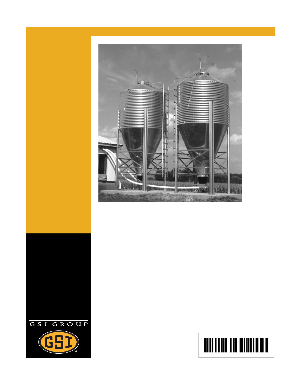
6', 7' & 9' Bulk Feed Tanks
Assembly Manual
PNEG-256
Date: 03-29-07
PNEG-256
Page 2

All information, illustrations, photos, and specifications in this manual are based on
the latest information available at the time of publication. The right is reserved to
make changes at any time without notice.
2 PNEG-256 6', 7' & 9' Bulk Feed Tanks
Page 3

Table of Contents
Contents
Chapter 1 Introduction ....................................................................................................................... 4
Chapter 2 Safety ................................................................................................................................. 5
Safety Guidelines ................................................................................................................ 5
General Safety Statement ................................................................................................... 6
Safety Instructions ............................................................................................................... 7
Prevent Wet Storage Stain .................................................................................................. 9
Chapter 3 Decals ............................................................................................................................... 10
Chapter 4 General Information ........................................................................................................ 13
Bulk Feed Tank Assembly Manual General Instructions .................................................. 13
Chapter 5 Foundation ....................................................................................................................... 15
Chapter 6 Sidewall Assembly .......................................................................................................... 21
Tank Side Walls ................................................................................................................21
Sidewall Sheet Orientation ................................................................................................ 23
Chapter 7 Roof .................................................................................................................................. 26
Sealed Roof Panels Installation ........................................................................................ 26
Peak Ring .......................................................................................................................... 27
Eave Safety Rail (6') ..........................................................................................................28
Eave Ladder ...................................................................................................................... 29
Peak Ring-Ladder ............................................................................................................. 30
Cap .................................................................................................................................... 32
Peak Ring .......................................................................................................................... 36
Chapter 8 Hopper Assembly ............................................................................................................ 37
Hopper Sheets ..................................................................................................................37
Chapter 9 Legs and Leg Braces ...................................................................................................... 44
Tank Legs and Leg Braces ............................................................................................... 44
Chapter 10 Ladder ............................................................................................................................ 52
Optional Sidewall Ladder ................................................................................................. 52
Safety Cage ..................................................................................................................... 54
Chapter 11 Raising Bin ..................................................................................................................... 56
Raising Bin to set on Foundation ..................................................................................... 56
Chapter 12 Grounding ...................................................................................................................... 58
Bin Grounding Instructions ............................................................................................... 58
Chapter 13 Pneumatic Fill Kit Assembly ........................................................................................59
Roof Panel ....................................................................................................................... 59
Chapter 14 Parts Section ................................................................................................................. 61
6' Diameter 60° Hopper Bin Specifications ...................................................................... 62
6' Diameter 60° Hopper Bin Specifications ...................................................................... 64
7' Diameter 67° Hopper Bin Specifications ...................................................................... 66
7' Diameter 67° Hopper Bin Specifications ...................................................................... 68
7' Diameter 45° Hopper Bin Specifications ...................................................................... 70
7' Diameter 45° Hopper Bin Specifications ...................................................................... 72
9' Diameter 60° Hopper Bin Specifications ...................................................................... 74
9' Diameter 60° Hopper Tank Specifications ................................................................... 76
9' Diameter 45° Hopper Bin Specifications ...................................................................... 78
9' Diameter 45° Hopper Bin Specifications ...................................................................... 80
Chapter 15 Warranty ......................................................................................................................... 83
PNEG-256 6', 7' & 9' Bulk Feed Tanks 3
Page 4

1. INTRODUCTION
READ THIS MANUAL carefully to learn how to properly use and install equipment. Failure to do
so could result in personal injury or equipment damage.
INSPECT the shipment immediately upon arrival. The Customer is responsible for ensuring that
all quantities are correct. Report any damage or shortages by recording a detailed description
on the Bill of Lading to justify the Customer’s claim from the Transport Firm. Our responsibility
for damage to the equipment ends with acceptance by the delivering carrier. Save all paperwork
and documentation furnished with any of the equipment/components.
THIS MANUAL SHOULD BE CONSIDERED a permanent part of your equipment and should be
easily accessible when needed.
WARRANTY is provided as part of the company’s support program for customers who use and
maintain their equipment as described in the manual. The warranty is explained on the warranty
page located on the inside of the back cover of this manual.
This warranty provides you the assurance that the company will back its products where defects
appear within the warranty period. In some circumstances, the company also provides field
improvements, often without charge to the customer, even if the product is out of warranty.
Should the equipment be abused, or modified to change its performance beyond the factory
specifications, the warranty will become void and field improvements may be denied.
4 PNEG-256 6', 7' & 9' Bulk Feed Tanks
Page 5
E
T
A
2
.
Safety Guidelines
This manual contains information that is important for you, the owner/operator, to know and
understand. This information relates to protecting personal safety and preventing equipment
problems. It is the responsibility of the owner/operator to inform anyone operating or working in
the area of this equipment of these safety guidelines. To help you recognize this information, we
use the symbols that are defined below. Please read the manual and pay attention to these
sections. Failure to read this manual and it’s safety instructions is a misuse of the equipment and
may lead to serious injury or death.
This is the safety alert symbol. It is used to alert you to
potential personal injury hazards. Obey all safety
messages that follow this symbol to avoid possible
injury or death.
F
S
Y
DANGER
WARNING
CAUTION
CAUTION
NOTE
DANGER indicates an imminently hazardous situation
which, if not avoided, will result in death or serious
injury.
WARNING indicates a potentially hazardous
situation which, if not avoided, could result in death or
serious injury.
CAUTION indicates a potentially hazardous situation
which, if not avoided, may result in minor or moderate
injury.
CAUTION used without the safety alert symbol
indicates a potentially hazardous situation which, if not
avoided, may result in property damage.
NOTE indicates information about the equipment that
you should pay special attention to.
PNEG-256 6', 7' & 9' Bulk Feed Tanks 5
Page 6
2. SAFETY
General Safety Statement
Our principle concern is your safety and the safety of others associated with grain handling
equipment. This manual is to help you understand safe operating procedures and some
problems which may be encountered by the operator and other personnel.
As owner and/or operator, it is your responsibility to know what requirements, hazards and
precautions exist, and to inform all personnel associated with the equipment or in the area.
Safety precautions may be required from the personnel. Avoid any alterations to the equipment.
Such alterations may produce a very dangerous situation, where serious injury or death may
occur.
You should consider the location of the bin site relative to power line locations or electrical
transmission equipment. We recommend you contact your local power company to review your
installation plan or for information concerning required equipment clearance. Clearance of
portable equipment that may be taken to the bin site should be reviewed and considered as well.
Any electrical control equipment in contact with the bin should be properly grounded and
installed in accordance with National Electric Code provisions and other local or national codes.
This product is intended for the use of grain storage only. Any other use is a misuse of the
product!
This product has sharp edges! These sharp edges may cause serious
injury. To avoid injury, handle sharp edges with caution and use proper
protective clothing and equipment at all times.
Sidewall bundles or sheets must be stored in a safe manner. The safest method of storing
sidewall bundles is laying horizontally with the arch of the sheet upward or over like a dome.
Sidewall sheets stored on edge must be secured in a way that they cannot fall over and cause
injury. Care should be taken in the handling and movement of sidewall bundles.
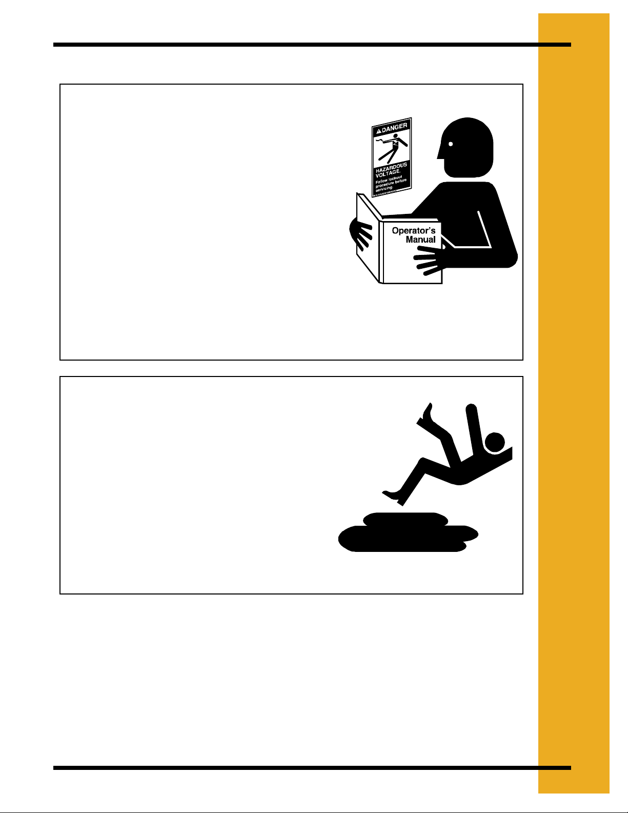
Personnel operating or working around equipment should read this manual. This manual must
be delivered with equipment to its owner. Failure to read this manual and its safety instructions
is a misuse of the equipment.
6 PNEG-256 6', 7' & 9' Bulk Feed Tanks
Page 7
Safety Instructions
Follow Safety Instructions
Carefully read all safety messages in this manual and
on your machine safety signs. Keep signs in good
condition. Replace missing or damaged safety signs.
Be sure new equipment components and repair parts
include the current safety signs. Replacement safety
signs are available from the manufacturer.
Learn how to operate the machine and how to use
controls properly. Do not let anyone operate without
instruction.
Keep your machinery in proper working condition.
Unauthorized modifications to the machine may
impair the function and/or safety and affect machine
life.
2. SAFETY
Read and Understand Manual
If you do not understand any part of this manual and
need assistance, contact your dealer.
Practice Safe Maintenance
Understand service procedures before doing work.
Keep area clean and dry.
Never lubricate, service, or adjust machine while it is
in operation. Keep hands, feet, and clothing from all
rotating parts.
Keep all parts in good condition and properly
installed. Fix damage immediately. Replace worn or
broken parts. Remove any build up grease, oil, or
debris.
Maintain Equipment and Work Area
PNEG-256 6', 7' & 9' Bulk Feed Tanks 7
Page 8
2. SAFETY
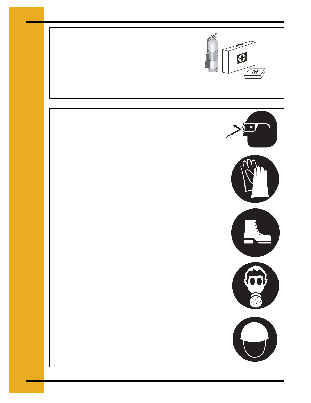
Prepare for Emergencies
Be prepared if fire starts.
Keep a first aid kit and fire extinguisher
handy.
Keep emergency numbers for doctors,
ambulance service, hospital, and fire
department near your telephone.
Wear Protective Clothing
Wear close fitting clothing and safety
equipment appropriate to the job.
Safety glasses should be worn at all times
to protect eyes from debris.
Keep Emergency Equipment Quickly
Accessible
Eye Protection
Wear gloves to protect your hands from
sharp edges on plastic or steel parts.
Wear steel toe boots to help protect your
toes from falling debris.
A respirator may be needed if a hog house
has poor ventilation. Waste fumes can be
toxic.
Remove all jewelry.
Tuck in any loose or dangling shoe strings.
Gloves
Steel Toe Boots
Respirator
Long hair should be tied up and back.
Wear hard hat to help protect your head.
Hard Hat
8 PNEG-256 6', 7' & 9' Bulk Feed Tanks
Page 9

2. SAFETY
Prevent Wet Storage Stain
Properly Store Grain Bin/Silo Materials Prior to Construction to Prevent Wet Storage
Strain:
Wet storage stain (rust) will develop when closely packed bundles of galvanized material such
as sidewall and roof sheets have moisture present from any source. Roof and sidewall bundles
should be inspected on arrival for the presence of moisture. If moisture is present, moisture must
not be permitted to remain between the sheets. In the case of moisture presence, sheets or
panels should be separated immediately, wiped down, dried and sprayed with a light oil or diesel
fuel.
Where possible, sidewall bundles, roof sheets and other closely packed materials should be
stored in a dry, climate controlled building. Storage inside a dry building should be done if at all
possible. Where outdoor storage is unavoidable, the materials should be raised out of contact
from the ground or vegetation. Stacking and spacing materials should not be corrosive or wet.
Materials must be protected from the weather. Weather protection that permits more air
movement around the bundles is best.
The storage method of the roof bundles and sidewall sheets may also help minimize moisture
presence. Roof bundles should be stored inclined. The bundles should be stored and secured
in a safe & stable manner. Turning the bundles over and storing with the center of the dome “up”
like a arch is an option. Sidewall bundles may be stored on edge, however these bundles
should be secured in such as way as they cannot fall over and cause injury.
Should “white rust” or “wet storage stain” occur, contact the manufacturer immediately
concerning methods to minimize the adverse effect upon the galvanized coating.
PNEG-256 6', 7' & 9' Bulk Feed Tanks 9
Page 10
3. DECALS
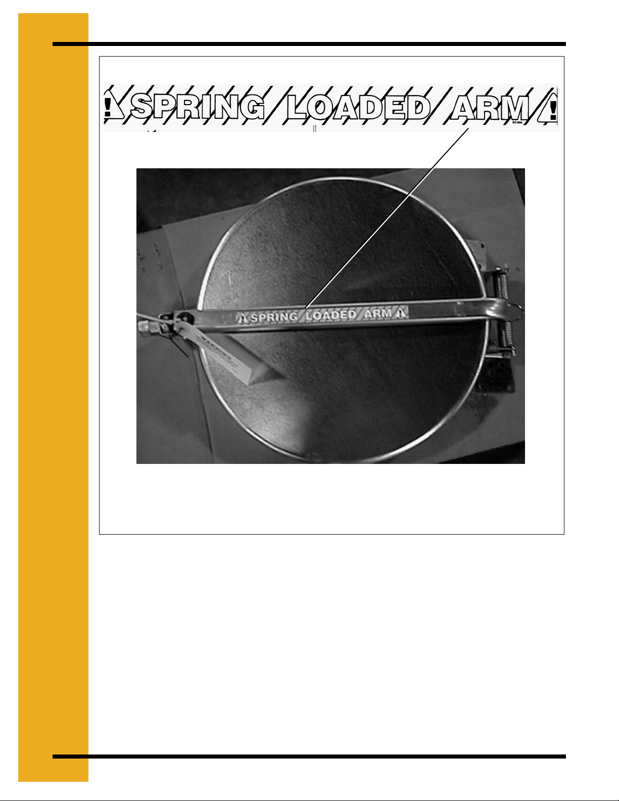
DC-604
DC-604 located on the Cap Latch Control Arm.
10 PNEG-256 6', 7' & 9' Bulk Feed Tanks
Page 11
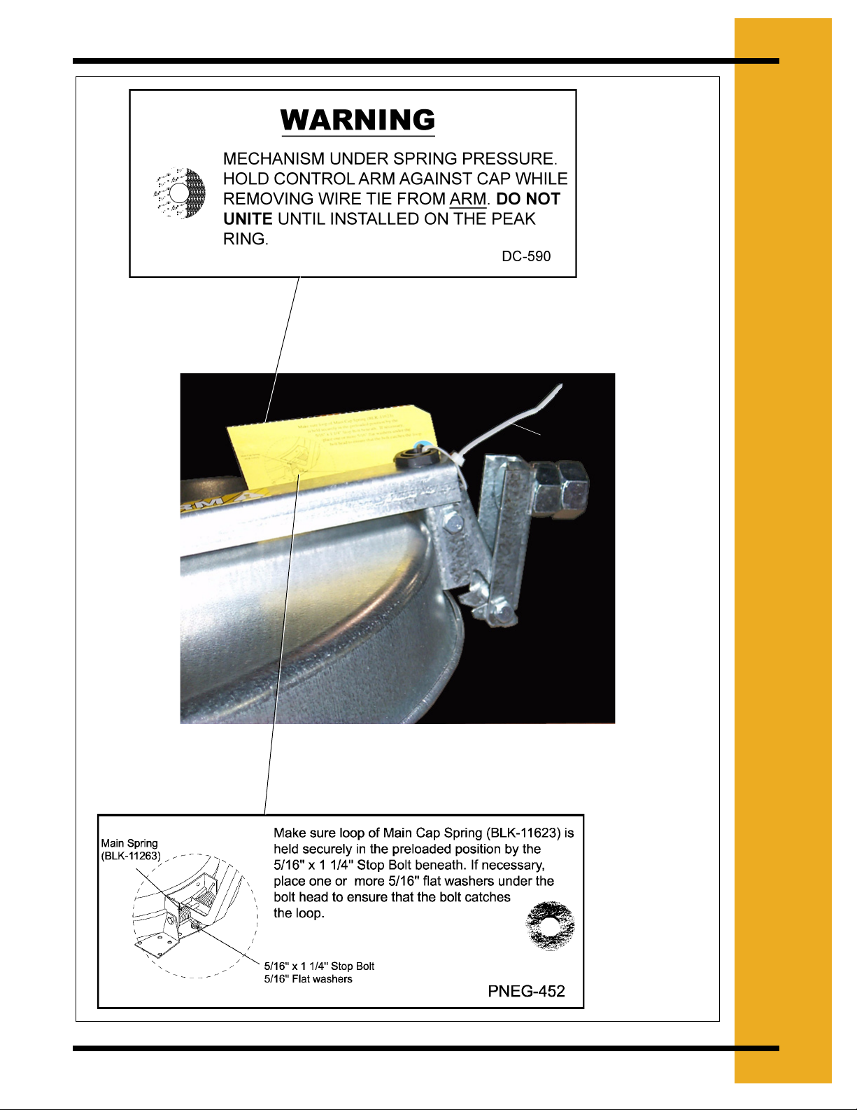
DC-590 located on the Cap
Latch Control Arm
Wire Tie
3. DECALS
PNEG-256 6', 7' & 9' Bulk Feed Tanks 11
Page 12
3. DECALS
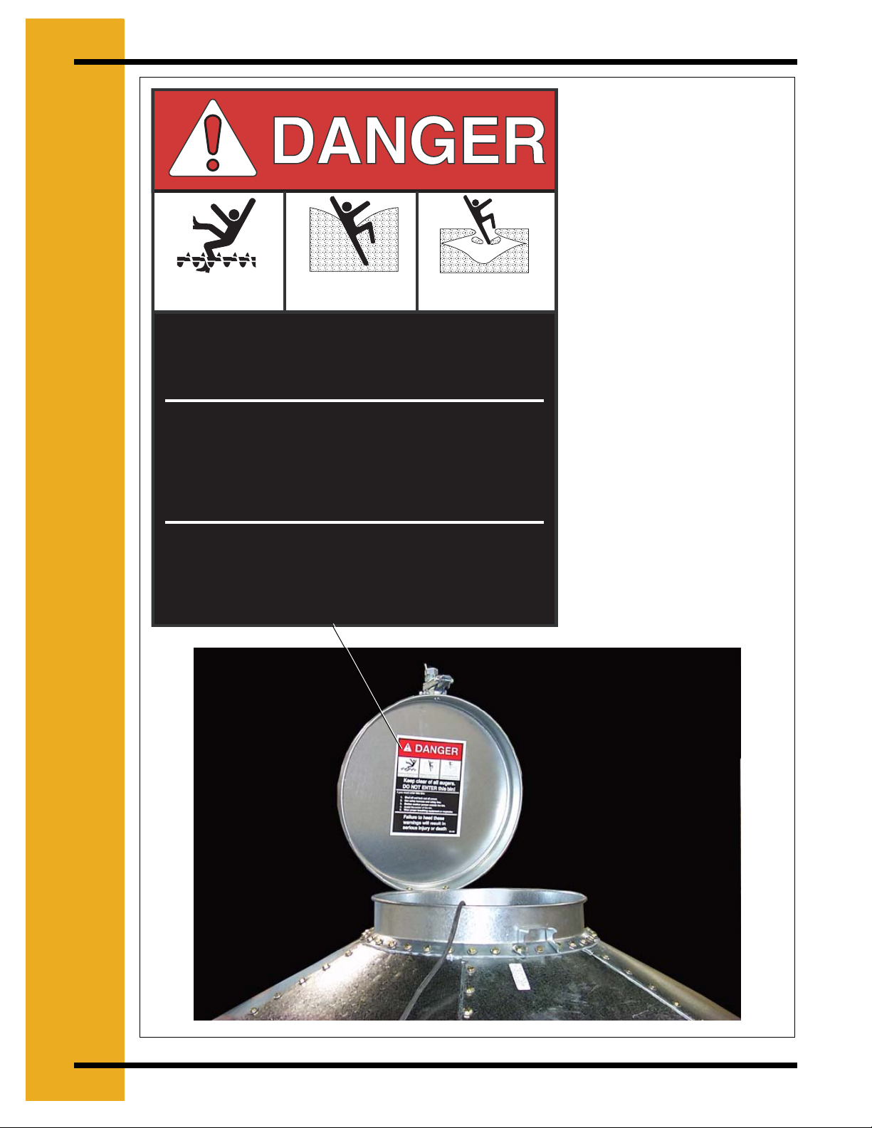
Rotating flighting will
kill or dismember.
Flowing material will
trap and suffocate.
Crusted material will
collapse and suffocate.
Keep clear of all augers.
DO NOT ENTER this bin!
If you must enter the bin:
1. Shut OFF and lock out all power.
2. Use a safety harness and safety line.
3. Station another person outside the bin.
4. Avoid the center of the bin.
5. Wear proper breathing equipment or respirator.
For Replacement Decals
Contact
P.O.Box 20
1004E. Illinois Street
Assumption IL, 62510-0020
Phone:1-217-226-4421
Failure to heed these
warnings will result in
serious injury or death.
DC-GBC-1A located on
Inside the Peak Cap
DC-GBC-1A
12 PNEG-256 6', 7' & 9' Bulk Feed Tanks
Page 13

I
O
4
R
M
A
O
I
N
A
E
N
E
G
.
R
L
F
T
N
Bulk Feed Tank Assembly Manual General Instructions
This product is intended for the use of storing feed only. Any other use is a misuse of the product!
While every effort has been made to keep the edges from being sharp, please wear the proper
protective clothing while erecting the bulk feed tank.
Our company recommends that you contact your local power company and have a
representative review your installation so your wiring will be compatible with their system and so
that you will have adequate power supplied to your unit.
A bulk feed tank weighs a minimum of 444 lbs (201 kg). All precautions should be taken when
raising the tank to its feet. Follow the instructions given later in this manual.
The safety pages show you where you can find the safety decals. The photographs show exactly
where the decals should be. If a decal has been damaged or is missing contact our company for
a free replacement.
First, read the Assembly Manual completely before starting to assemble your Bulk Feed Tank.
Check your shipment with the packing list to be sure there are no shortages.
1. Decal protective mask must be removed when assembling tank. Mask may become difficult
to remove if left exposed to sunlight.
2. Vertical seams must be staggered on all sidewall rings.
3. When legs extend up two rings, the leg holes must be in alignment in the bottom two rings.
4. All hopper seams and the hopper collar use truss head bolts. The heads of the bolts must
be on the inside of the tank.
5. All bolts are to be tightened from the nut side only. Do not allow bolt heads to spin.
6. Hex head bin bolts are used on all sidewall and roof seams with the bolt heads on the
outside of the bin.
7. Hex head bolts are to be used on all leg to sidewall connections with the bolt heads on the
inside of the tank.
8. 7' diameter sidewall sheets must be bolted together so there is 65-5/8'' between leg holes.
(Refer to Page 66).
9. Drift punches can be used to align holes.
10. All vertical sidewall sheet seams must be overlapped in the same direction.
11. A hole spacing of 3-1/8'' is used at the top of all top sidewall sheets and at the bottom of
all bottom sidewall sheets.
PNEG-256 6', 7' & 9' Bulk Feed Tanks 13
Page 14

4. GENERAL INFORMATION
Selecting the Proper Site
The selected site should be level, firm and free from underlying debris. The tank can be installed
satisfactorily on slopes, but as the slope increases, additional labor and materials are required
for the foundation. The concrete foundation surfaces must be level. If some fill is required, it
should be watered and tamped thoroughly to prevent uneven settling from the weight of the tank.
Good water drainage should be provided to prevent water collecting under or around the tank.
Naturally, the site must allow convenient access for easy loading and unloading, plus provide
additional space for future units. Also, consider the positioning of handling equipment, availability
of electricity, etc.
Tools
Tools recommended for assembly of Bulk Feed Tanks.
1. Assorted sizes of combination wrenches
2. Hammer
3. 3-12'' long drift punches
4. 1 Large Flathead Screwdriver
5. 1 Pair of slip joint pliers
6. 2 Adjustable wrenches
7. Ratchet and sockets
8. Impact wrenches and sockets (if available).
14 PNEG-256 6', 7' & 9' Bulk Feed Tanks
Page 15
5
I
O
T
N
D
N
A
.
U
F
O
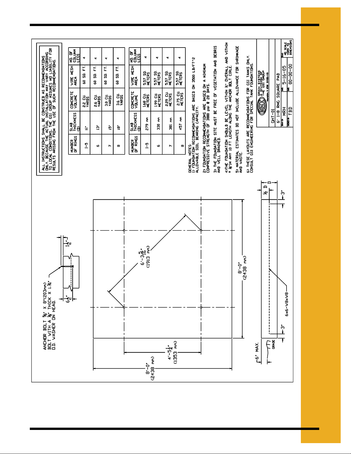
Figure 5A
PNEG-256 6', 7' & 9' Bulk Feed Tanks 15
Page 16
5. FOUNDATION
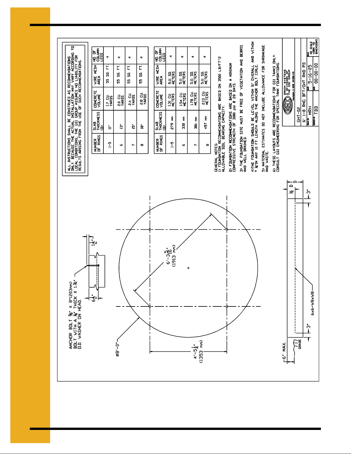
Figure 5B
16 PNEG-256 6', 7' & 9' Bulk Feed Tanks
Page 17
5. FOUNDATION
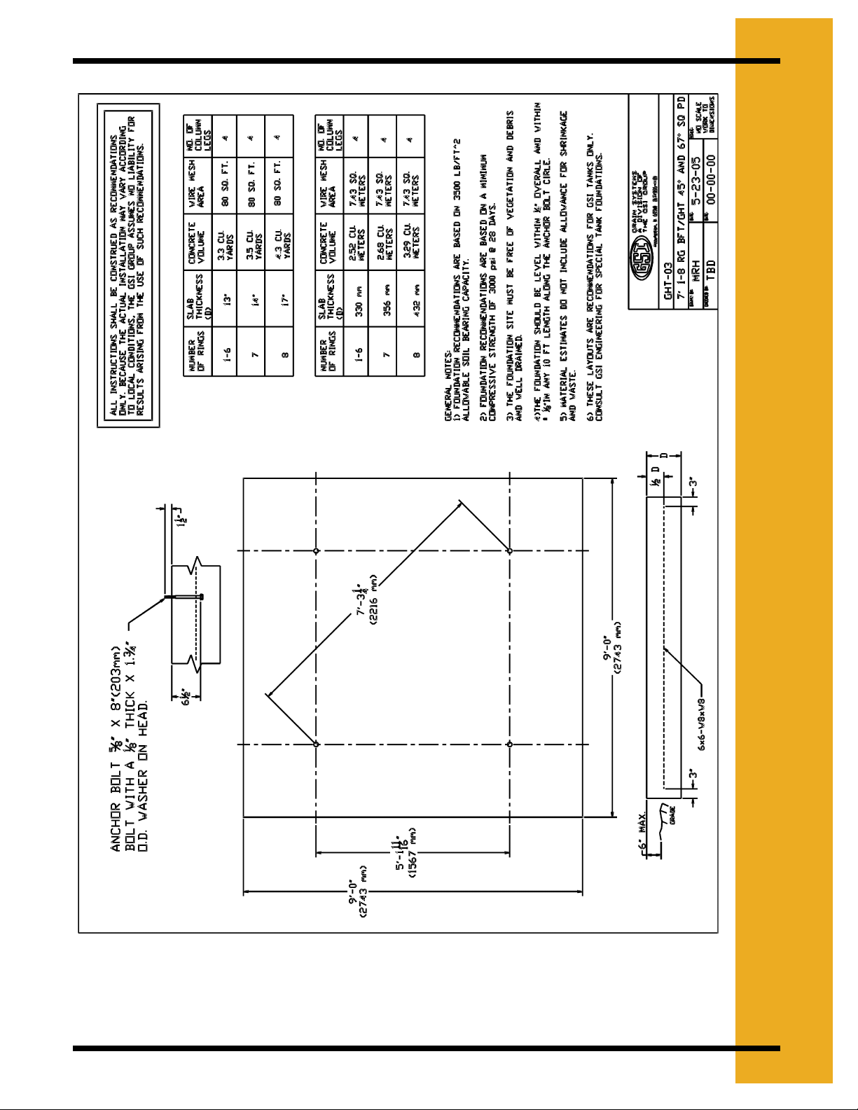
Figure 5C
PNEG-256 6', 7' & 9' Bulk Feed Tanks 17
Page 18
5. FOUNDATION
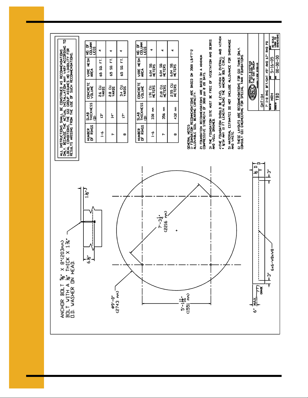
Figure 5D
18 PNEG-256 6', 7' & 9' Bulk Feed Tanks
Page 19
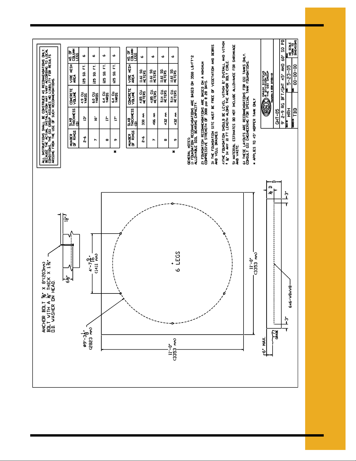
5. FOUNDATION
Figure 5E
PNEG-256 6', 7' & 9' Bulk Feed Tanks 19
Page 20
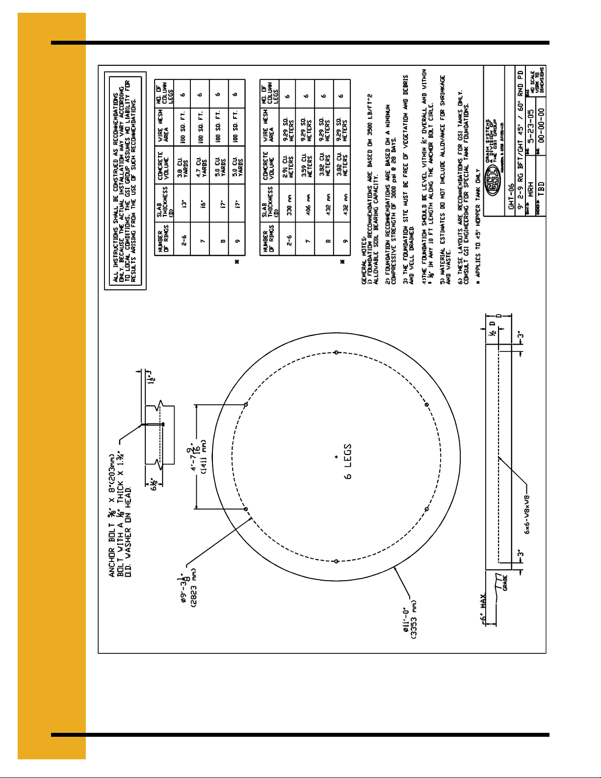
5. FOUNDATION
Figure 5F
20 PNEG-256 6', 7' & 9' Bulk Feed Tanks
Page 21
Tank Side Walls
I
6
Sidewall Sheet Gauge Chart
Model Gauge
BFT 6'-1 Ring 20
BFT 6'-2 Ring 20-20
BFT 6'-3 Ring 18-20-20
BFT 6'-4 Ring 18-20-20-20
BFT 7'-1 Ring 20
BFT 7'-2 Ring 18-20
BFT 7'-3 Ring 18-20-20
BFT 7'-4 Ring 18-18-20-20
BFT 7'-5 Ring 17-17-18-20-20
BFT 7'-6 Ring 15-15-17-18-20-20
BFT 9'-1 Ring 20
BFT 9'-2 Ring 20-20
BFT 9'-3 Ring 20-20-20
BFT 9'-4 Ring 18-18-20-20
BFT 9'-5 Ring 17-17-18-20-20
BFT 9'-6 Ring 15-15-17-18-20-20
D
.
S
E
W
A
L
L
B
L
E
S
M
A
S
Y
How to Use Chart on this Page
The chart labeled “Sidewall Sheet Gauge Chart” is for your reference when building the tank.
This chart tells you what gauges your rings of your specific tank must have. To read the chart
you look up the tank size you are building (a 7 foot diameter tank with 4 rings is referred to as
BFT 7'-4 Ring). The side labeled “Gauge” will indicate which sidewall sheets to use. The sheets
are color coded, all that needs to be done is to match the gauge number with the color
(use “Sheet Gauge Color Chart”).
Note: Sidewall sheets are color coded on edges for gauge identification.
Sheet Gauge Color Chart
Code # Color
20 Red
18 Orange
17 Pink/Light Blue
16 Blue
15 Brown/Red
14 Green
13 yellow/Blue
12 Black
11 Pink
10 Light Blue
PNEG-256 6', 7' & 9' Bulk Feed Tanks 21
Page 22
6. SIDEWALL ASSEMBLY
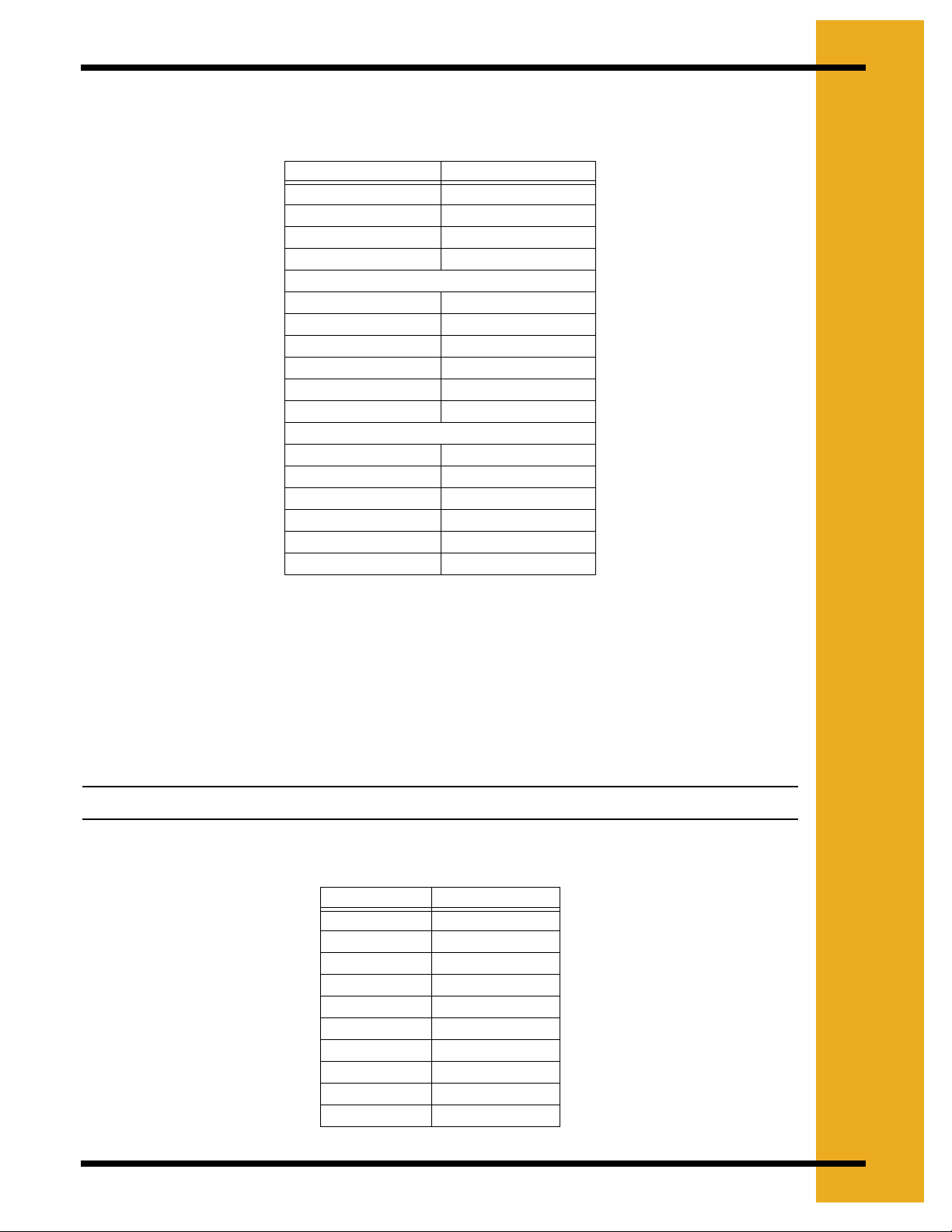
Caulking
Figure 6A Caulking Detail
Note: The rope caulking is installed before each sheet is assembled. Wipe sheet clean
where it is to be applied. Apply caulking on each side of the holes on the vertical
seams and also on each side of the horizontal row of holes.
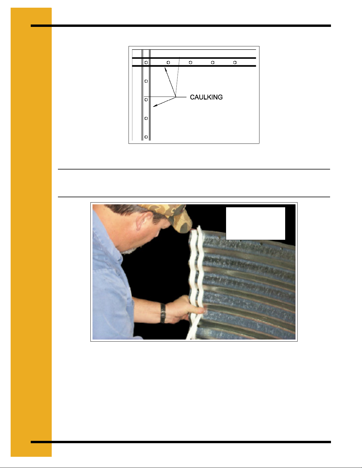
Figure 6B
Caulking is to be
applied to all BFT
parts before
assembly.
22 PNEG-256 6', 7' & 9' Bulk Feed Tanks
Page 23
6. SIDEWALL ASSEMBLY
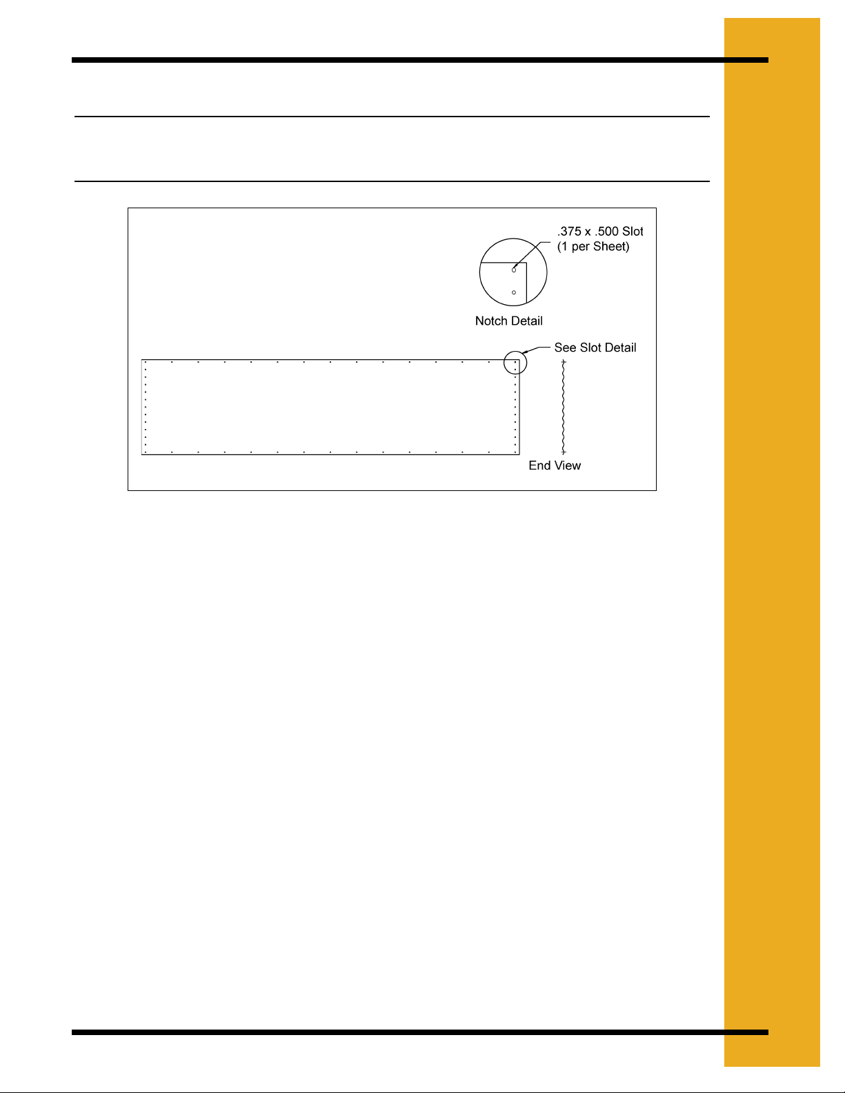
Sidewall Sheet Orientation
Important: Please note the sheet orientation when assembling the bin sidewall. The
upper right corner will have a slot or identifying sticker. This corner should be
on the inside of the tank when assembled.
Figure 6C Viewed from inside
Sheet orientation will effect how the sheets lap together.
Sidewall Assembly
Start by assembling the top ring of the Bulk Feed Tank. The top row of bolt holes has 3-1/8"
spacing in the top ring. Before bolting the sidewall sheets together, check that you have the
proper gauge steel for the top ring. The higher gauge number denotes thinner material.
(Example, 20 gauge material is thinner than 14 gauge.) In assembling all bulk feed tanks the
thinnest material always go on top. The heaviest corrugated sidewall sheet will be located on the
bottom of the tank. Check the various gauges of your tank with the “Sheet Gauge Color Code
Chart” & “Sidewall Sheet Gauge Chart”, Page 21 and Page 21.) Begin by putting the rings
together on the edge of the sheets. On 7'-1 ring tanks ensure vertical leg seams are spaced
equally around tank. (Refer to Page 66.) After the first ring is complete the roof needs to be
assembled. The pages that follow give the proper instructions for this. After the roof is assembled
the tank can be rolled on its side for easier sidewall assembly. (See Figure 6D)
All bolts are to be tightened from the nut side only!
Continue to add rings with lighter gauges first, then heavier gauges. The next row of sidewall
sheets go to the inside of the previous row of sidewall panels. Do not forget to place the caulking
between every ring.
Be sure to stagger all vertical seams between rows.
PNEG-256 6', 7' & 9' Bulk Feed Tanks 23
Page 24
6. SIDEWALL ASSEMBLY
Upper Ring
5/16'' x 3/4''
5/16'' Nut
Caulking
Figure 6D Ring Overlap Detail
Tighten bolts from the
nut side only.
Lower
First Ring Assembly
Figure 6E
Important: BOLTING PATTERN BEGINS IN THE CENTER OF THE SHEET! When starting
to assemble the sidewall rings to one another, be sure to start in the center of
the sheet and work to the outside edges (horizontal seams). This allows the
sidewall to draw up evenly.
24 PNEG-256 6', 7' & 9' Bulk Feed Tanks
Page 25

6. SIDEWALL ASSEMBLY
Sidewall Assembly
Figure 6F
It is easier to put on more sidewall sheets with the tank on its side. It can be rolled easily from
side-to-side to allow the bolts and nuts to be put in the proper holes. (The roof is, however,
assembled on the first ring before rolling it over to its side.)
PNEG-256 6', 7' & 9' Bulk Feed Tanks 25
Page 26
7. ROOF
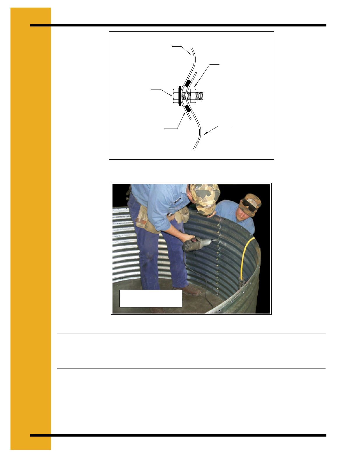
Sealed Roof Panels Installation
Note that the roof and sidewall ladders are centered on a roof seam. Take notice when placing
roof panel, that the outside edge is bent down. This edge is to be placed on the outside of other
roof panel to form a tight seal. Be sure to apply two strips of caulking on all seams. Assemble
roof panels in a counter clockwise manner.
Lining up holes and placing bolts
Figure 7A
Figure 7B
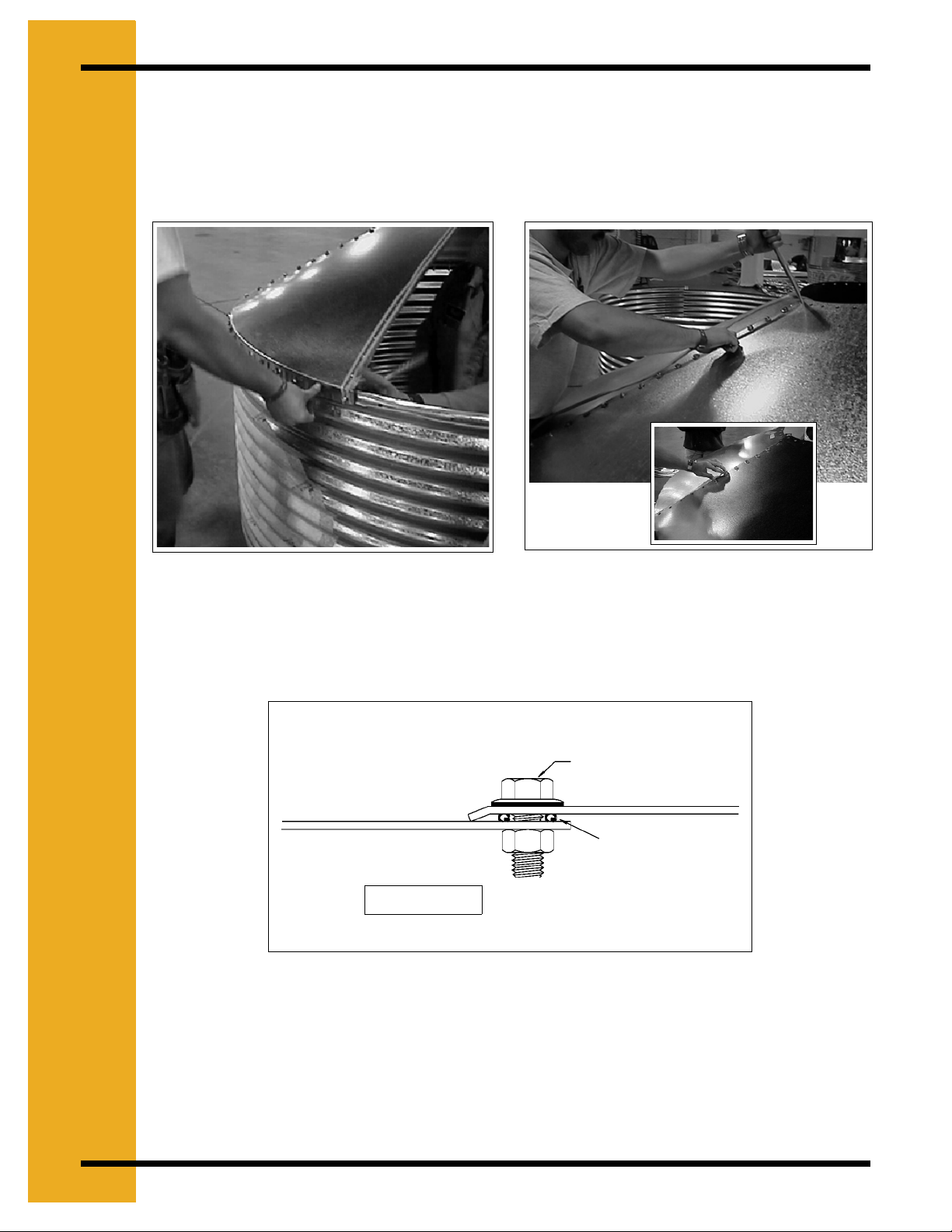
Assemble roof panels in a counter clockwise manner. On bins that will be equipped with a
pneumatic fill system (refer to Page 59), the two roof panels with fill hole and exhaust hole should
be located opposite each other on the bulk feed tank. The peak ring may now be installed.
5/16'' x 3/4'' Bin
Blot
Caulking
(2 Strips)
Inside of Tank
Figure 7C Roof Sheet Overlap Detail
26 PNEG-256 6', 7' & 9' Bulk Feed Tanks
Page 27

7. ROOF
Caulki
Peak Ring
Peak Ring Collar to Roof Panels
Use two strips of caulking between peak ring and roof panels (See Figure 7E). Note that the peak
ring goes on the outside of the roof panels.
Peak Ring Collar
Inside of Tank
Roof Sheet
ng
(2 Strips)
5/16'' x 3/4'' Bin Blot
Caulking
Figure 7D Peak Ring Collar Detail
Peak Ring
5/16'' x 3/4''
Bin Bolt
Figure 7F
Figure 7E
PNEG-256 6', 7' & 9' Bulk Feed Tanks 27
Page 28

7. ROOF
Eave Safety Rail (6')
(See Figure 7H)
(See Figure 7I)
(See Figure 7J)
Figure 7G 6' Roof Eave Safety Rail Detail
6' Roof Safety Rail Detail
Ref # Part # Qty Description
1L BLK-11877L 1 6' BFT Left Hand Roof Eave Safety Rail
1R BLK-11877R 1 6' BFT Right Hand Roof Eave Safety Rail
3 S-275 6 5/16'' x 3/4'' Bin Bolt
5 S-396 6 5/16'' - 18 Hex Nut
6 BLK-11673 -- Lower Support Channel Bracket
7 LDR-4002 -- 44'' Sidewall Ladder Section
8 LS-121 -- Sidewall Ladder Standoff
Field drill two (2) 3/8'' Dia. holes in 6' roof for safety rail attachment. Use bin bolt sealing washer
between roof and rail. Note left and right positioning so it will fall between the legs when tank is
complete.
28 PNEG-256 6', 7' & 9' Bulk Feed Tanks
Page 29

Figure 7H
7. ROOF
Figure 7I
Figure 7J
Eave Ladder
Note: Ladder is symmetrical about roof seam. One side shown for clarity.
Figure 7K 7' & 9' Roof Eave Ladder Detail
PNEG-256 6', 7' & 9' Bulk Feed Tanks 29
Page 30

7. ROOF
7' & 9' Roof Eave Ladder Detail
Ref # Part #
1 BLK-11680 2 2 Ladder Eave Safety Ring
2 BLK-11760 2 -- 7' BFT Roof Ladder Support Channel
BLK-11761 -- 2 9' BFT Roof Ladder Support Channel
3 S-275 16 18 5/16'' x 3/4'' Bin Bolt
4 BLK-11679 2 3 Roof Ladder Rung
5 S-396 16 18 5/16'' - 18 Hex Nut
6 BLK-11673 2 2 Lower Support Channel Bracket
7 LDR-4002 -- -- 44'' Sidewall Ladder Bracket
8 LS-121 -- -- Sidewall Ladder Standoff
Qty 7'
Dia
Qty 9'
Dia
Description
Peak Ring-Ladder
Bolt Spacing Used for Roof
Ladder Attachment
Figure 7L
*Possible Cap Latch
Locations
Roof Seam
Bolt Spacing Used for
Roof Ladder Attachment
Figure 7M 7'-9' Roof Ladder Peak Ring Detail
30 PNEG-256 6', 7' & 9' Bulk Feed Tanks
Page 31

7. ROOF
Figure 7N
Note: Three (3) hole spaces on either side of center line of ladder. (Six (6) spaces
between brackets).
7' & 9' Roof Eave Ladder Detail
Ref # Part # Qty 7' Dia Qty 9' Dia Description
1 LS-147 2 2 Inside Ladder Standoff
2 BLK-11760 2 -- 7' BFT Roof Ladder Support Channel
2 BLK-11761 -- 2 9' BFT Roof Ladder Support Channel
3 S-275 16 18 5/16'' x 3/4'' Bin Bolt
4 BLK-11679 2 3 Roof Ladder Rung
5 S-396 16 18 5/16'' - 18 Hex Nut
Note that peak ring is mounted to the outside of the roof panels. 6' Bulk Feed Tank utilizes only
eave safety rail. See Page 29 for details.
Note: Center roof ladder over roof seam during assembly. Ladder is symmetrical about
roof seam. One side shown for clarity.
PNEG-256 6', 7' & 9' Bulk Feed Tanks 31
Page 32

7. ROOF
Cap
Roof Cap Ground Control
See Figure 7P
Figure 7O
Ground control comes standard on 6'-60°, 7-67° and 9'-60° Bulk Feed Tanks. Ground Control is
optional on all 45° Bulk Feed Tanks. Ground control components come fully assembled for your
convenience. The ground control is shipped with the control arm secured for safety and shipping
purposes. The short chain and retaining tie are intended for shipping use only.
Important: Adjust Chain
in this Area as Explained
Below
See Figure 7Q
See Figure 7R
CAUTION
The control arm is spring loaded. Be careful when removing shipping retainers.
Chain Route
Cotter Pin
Figure 7P
32 PNEG-256 6', 7' & 9' Bulk Feed Tanks
Page 33

7. ROOF
Refer to the Control Arm Detail and Cap Latch Detail on for component part assembly. The cap
latch hook, located opposite the cap hinge, latches over the BLK-11846 Hold Down Bracket
(Item 20, Cap Latch Detail on Page 19). One end of the ground control chain is secured at the
counterweight arm with a cotter pin (See Figure 7P). The chain is passed up and over the cap,
through the grommet on the pivot arm, and through the Roof Eave Bracket (BLK-11950), then
continues down the side of the tank.
After removing the slack from the ground control chain while in the fully closed and latched
position. Install the key ring clip 2'' below chain holder bracket (See Figure 7R). Ensure that the
key ring allows the cap to fully latch when the cap is in the closed position, yet will not allow the
chain enough slack on top of the cap to become wrapped around the pivot arm in a high wind
condition.
Roof Eave Bracket
BLK-11950
Figure 7Q
Make sure the loop of the Main Cap Spring (BLK-11623) is held securely in the preloaded
position by the head of the 5/16" Bolt beneath (Item 4, Control Arm Detail See Figure 7T). If
necessary, place one or more 5/16" flat washers under the bolt head to ensure that the bolt
catches the loop. See Stop Bolt Detail on Page 34.
Chain Holder
BLK-11949
Handle
Key Ring
Figure 7R
PNEG-256 6', 7' & 9' Bulk Feed Tanks 33
Page 34

7. ROOF
Bolt the Chain Holder (BLK-11949) to the bottom horizontal row of sidewall holes, or field drill
and bolt to the leg tie brace (See Figure 7R). Two (2) 4'' plastic handles and extra key ring clips
are provided for use at the hopper eave to be used as fully open and fully closed cap indicators.
Make sure the loop of the Main Cap Spring
(BLK-11623) is held securely in the preloaded
position by the head of the 5/16'' bolt beneath.
If necessary, place one or more 5/16'' flat
Washers under the bolt head to ensure
that the bolt catches the loop.
Figure 7S
WARNING
The control arm is spring loaded. It must be released while on the ground and before
attaching it to the peak ring. Failure to do so will result in serious injury.
Note: Use the chart on Page 19 for Control Arm and Ground Control details.
Right Hinge
Attachment Holes
Left Hinge
Attachment Holes
Figure 7T Control Arm Detail
Spring Stop Attachment Hole
34 PNEG-256 6', 7' & 9' Bulk Feed Tanks
Page 35

7. ROOF
20
18
19
8
17
10
16
15
14
Figure 7U Ground Control Detail
Parts List for Control Arm and Ground Control
Ref # Part # Description
1 BLK-11735 Control Arm
2 BLK-11876 Nylon Grommet with Nut
3 BLK-11623 Flush Cap Main Spring
4 S-277 5/16'' - 18 x 1.25'' Bin Bolt (Grade 5)
5 S-845 5/16'' Wrought Iron Washer (Grade 2)
6 BLK-11842 Lower Cap Hinge
7 BLK-11734 Upper Cap Hinge
8 S-7329 5/16'' - 18 x 2'' Hex Head Bolt
9 BLK-10015 Bulk Tank Roof Cap
10 S-5220 5/16'' - 18 Hex Lock Nut (Grade 2)
11 BLK-11503 1.875'' Long Spring Spacer
12 BLK-11730 1 Piece Bulk Tank Peak Ring
13 S-7171 3/8'' - 16 x 6.5'' Hex Head Bolt (Grade 5)
14 S-3214 7/8'' - 9 Hex Nut (Grade 2)
15 BLK-11845 Latch Counterweight
16 S-7281 7/8'' - 9 x 1.5'' Hex Head Bolt
17 BLK-11844 Peak Cap Latch
18 BLK-11795 0.938'' x 0.750 Dia. Plastic Spacer
19 BLK-11843 Pivot Bracket
20 BLK-11846 Cap Hold Down Bracket
21 S-4663 3/8'' - 16 Hex Head Lock Nut
9
PNEG-256 6', 7' & 9' Bulk Feed Tanks 35
Page 36

7. ROOF
s
Peak Ring
BLK-10472 Bulb
Seal
S-7120 5/16''
3.1/2'' Bolt
CRP-4654
Cap Hold
Down
CRP-4639 Cap
Hold Down
Bracket
Figure 7V Bulb Seal Kit (Optional)
BLK-10022
Cap Latch
Left Hinge
Attachment Hole
Figure 7W Cap Hold Down Package
Right Hinge
Attachment
Holes
Note: Bulb seal kit is included with all pneumatic fill kits. When ordered as a separate
option, specify Part No. BLK-10472.
Cap Hold Down Package comes standard on all 45° hopper bulk tanks., Optional on all 60° and
67° hopper bulk tanks.
36 PNEG-256 6', 7' & 9' Bulk Feed Tanks
Page 37

B
L
8
E
S
M
A
R
S
O
P
.
H
E
P
Y
Hopper Sheets
When starting to attach hopper sheets to sidewall it is recommend that the first hopper sheet
seam be positioned halfway between leg positions. Lap the hopper sheets as shown. Use two
(2) strips of caulking on all seams at sidewall to hopper and hopper sheet to hopper sheet. Be
sure to place the head of the truss bolt on the inside of hopper. Leave one hopper sheet out to
allow room to install hopper collar. Be sure to use two (2) strips of caulking between hopper collar
and hopper sheets, then put last hopper sheet in place.
CAUTION
All 9' diameter 60° 3-6 ring and 7' diameter 67° 5 & 6 ring tanks require hopper
reinforcement angles. Angle covers entire seam (including hopper collar).
Note: When used for 22" (559 mm)
hopper openings, field cut brace
below slot to fit properly.
Hopper Sheet to
Sidewall Sheet
Hopper Reinforcement
Angle
Figure 8A
Figure 8B
PNEG-256 6', 7' & 9' Bulk Feed Tanks 37
Page 38

8. HOPPER ASSEMBLY
Sidewall Sheet
Use two Strips of
Caulking
Use 5/16'' x 1-1/4'' Bin
Bolts
Inside of Tank
Hopper sheet
Figure 8C
9' 60° Leg Attachment (for 9' 60° Tanks Only)
Curved Washer are supplied in the hardware packages. These washers must be installed at the
Bottom Leg to Sidewall Bolt Connection, to the inside of the Hopper Panel as indicated in the
Illustration Below.
Apply caulking in between the hopper panel and the sidewall sheet.
Sidewall Sheet
5/16" Hex Nut (S-396)
10 Ga. Curved
Washer (Blk-12483)
5/16" x 1-1/4" Bin
Bolt (S-277)
Leg
Figure 8D
Hopper Panel
38 PNEG-256 6', 7' & 9' Bulk Feed Tanks
Page 39

Inside of Tank
Hopper Panel
Figure 8E
8. HOPPER ASSEMBLY
Reinforcement
Angle
Inside of Tank
Hopper Sheet
Section “A” - “A”
Caulking (2 Strips)
Hopper Sheet
Reinforcement Angle
Figure 8F Hopper Overlap and Bolt Detail W/Reinforcement Angle
Bolt head to be on inside of
hopper.
Hopper Sheet
5/16" x 3/4" Truss
Head Bolts
Hopper Sheet
Inside of Tank
Flange Nut
Caulking (2 Strips)
Figure 8G Hopper Overlap and Bolt Detail for Tanks W/Out
Reinforcement Angle
PNEG-256 6', 7' & 9' Bulk Feed Tanks 39
Page 40

8. HOPPER ASSEMBLY
Reinforcement Angles
Note: Every hole in the hopper sheet will be utilized. Use 5/16" x 3/4" truss head bolt on
hopper seams. (Truss head goes on inside of hopper).
The 9' 3-6 ring, 60° & 7' 5-6 ring, 67° Ring tanks are the only once to use reinforcement
angles.
Note: Last (bottom) bolt in reinforcement angle goes through hopper collar also.
Hopper Collar
Before last hopper panel is attached, assemble the hopper extensions (if utilized) on the hopper
collar. Use 5/16'' truss head bolts, and caulk all joints on the assembly, attach to the hopper
panels, using 5/16'' truss head bolts. Be sure to caulk between hopper extensions and hopper
panels. (Refer to details on Figure 8I).
Figure 8H
40 PNEG-256 6', 7' & 9' Bulk Feed Tanks
Page 41

Hopper Panel
8. HOPPER ASSEMBLY
5/16" x 3/4" Truss
Head Bolt
Caulking
Flange Nut
16" or 22" Hopper or Hopper
Extension (if used)
5/16" x 3/4" Truss
Head Bolt
Caulking
Hopper
Extension
Inside of Tank
Bolt Detail: Hopper
Extension (if used)
Flange Nut
16" or 22" Hopper
Collar
Bolt Detail: Hopper
Collar
Inside of Tank
Figure 8I
PNEG-256 6', 7' & 9' Bulk Feed Tanks 41
Page 42

8. HOPPER ASSEMBLY
Install hopper collar before all hopper panels are assembled. Use 5/16" truss head bolts, as
shown in the illustration, on all hopper seams. Be sure to caulk between the hopper collar and
hopper panels. See Figure 8J, Figure 8K, Figure 8L.
22" Hopper Collar
Figure 8J 22'' Hopper Collar
22'' Hopper Collar
BLK-10854 45 Degree 22" Hopper Collar
BLK-10342 60 Degree 22" Hopper Collar
BLK-10341 67 Degree 22" Hopper Collar
16" Hopper Collar
Part # Description
Figure 8K 16'' Hopper Collar
16'' Hopper Collar
Part # Description
BLK-10489 6' - 16" 60 Degree (24 Holes)
BLK-10488 7' - 16" 67 Degree (24 Holes)
BLK-11463 *9' - 16" 60 Degree (27 Holes)
42 PNEG-256 6', 7' & 9' Bulk Feed Tanks
Page 43

8. HOPPER ASSEMBLY
Note: 9' 16" 60° Hopper Collar BLK-11463 is used with a 9' - 16" 60° tank only (27 Holes).
16" Hopper Collar
Figure 8L Hopper Extension Kit
22''-16" Hopper
Extension
Hopper Extension Kit
Part # Description
BLK-10847 16" 45° Hopper Extension & Collar (Standard on 7' & 9' 45 Degree)
BLK-10587 16" 60° Hopper Extension & Collar (Optional)
BLK-10591 16" 67° Hopper Extension & Collar (Optional)
PNEG-256 6', 7' & 9' Bulk Feed Tanks 43
Page 44

9. LEGS AND LEG BRACES
Tank Legs and Leg Braces
When installing legs to sidewall, reverse normal insertion procedure on bolts. Place hex head
and neoprene washer to inside of sidewall, leaving threaded portion of bolt protruding outward.
This provides for a weather tight seal at the leg attachment location. See on Page 44 to Page 46
for Leg Attachment to Sidewall Sheet details.
Figure 9A
Use 5/16" x 3/4" bin bolts and nuts when attaching the leg to base. Make sure the washer is used
on the slot side of the leg.
Leg
Back Leg Anchor Plate
BLK-10057 (1 Tab)
Front Leg Anchor Plate
BLK-10058 (2 Tab)
Figure 9B
44 PNEG-256 6', 7' & 9' Bulk Feed Tanks
Page 45

9. LEGS AND LEG BRACES
Line up leg with these holes and bolt (refer to drawing below)
6' tank leg shown
Figure 9C
5/16'' x 3/4'' Bin Bolts
Inside of Tank
Leg
Insert bolts inside to outside on all leg to tank connections.
Figure 9D
Figure 9E
PNEG-256 6', 7' & 9' Bulk Feed Tanks 45
Page 46

9. LEGS AND LEG BRACES
Leg Size Chart
Tank Size Hopper Number of Rings Length Leg Coverage
6' Diameter 60 Degree 1-3 Rings 106-3/8'' 1-Ring
6' Diameter 60 Degree 4-Rings 106-3/8'' 1-Ring
7' Diameter 67 Degree 1-4 Rings 140-1/2'' 1-Ring
7' Diameter 67 Degree 5-6 Rings 164-1/2'' 1-3/4 Ring (56'')
7' Diameter 45 Degree 1-4 Rings 94-1/8'' 1-Ring
7' Diameter 45 Degree 5-6 Rings 120-3/4'' 1-3/4 Rings (56'')
9' Diameter 60 Degree 1-5 Rings 140-1/2'' 1-Ring
9' Diameter 60 Degree 6 Rings 164-1/2'' 1-3/4 Ring (56'')
9' Diameter 45 Degree 1-5 Rings 106-1/8'' 1-Ring
9' Diameter 45 Degree 6 Rings 132-3/4'' 1-3/4 Rings (56'')
One-Ring Leg 140-1/2'' (3569 mm)
13 Holes
Figure 9F Leg Adjustment (7' (1-4 ring) 67° & 9' (1-5 ring) 60° only)
10 Holes
Note: 9' 5 - Ring tanks must utilize two ring coverage legs if raising 8" (203.2 mm).
CAUTION
Failure to follow instructions may cause damage or failure of the equipment.
Depending on the size of the Bulk Feed Tank you are assembling, the leg will cover either the
bottom ring or 1-3/4 rings (56"). Refer to this chart to find the correct number of rings your legs
will cover. Put all legs on, but don't tighten bolts until all braces are in place. Be sure to put
leg braces on properly. (Refer to Page 47 to Page 51)
46 PNEG-256 6', 7' & 9' Bulk Feed Tanks
Page 47

9. LEGS AND LEG BRACES
Extra Clearance Leg Adjustment
In cases where extra clearance is required (on 7' 67° & 9' 60° tanks only), you may raise the tank
up to 8" when installing the legs. See details for proper positioning. Call Company's engineering
for any other special requirements.
Note: 9' 5 - Ring tanks must utilize two ring coverage legs if raising 8" (203.2 mm).
CAUTION
Failure to follow instructions may cause damage or failure of the equipment.
Bracing Hole Layout (60° & 67° Legs)
For 7' 67° and 9' 60° Feed Tank bracing layout see Page 48 and Page 49.
22 Holes
Figure 9G Leg Adjustment (7' (5-6 ring) 67° & 9' (6 ring) 60° only)
Two-Ring Leg 164 1/2" (4178 mm)
19 Holes
Figure 9H
PNEG-256 6', 7' & 9' Bulk Feed Tanks 47
Page 48

9. LEGS AND LEG BRACES
67.766''
Ladder Standoff (All
.375'' Dia Hole
31.766''
Ladder Standoff 2-4-6
Rings .375'' Dia Hole
9.813''
29.938''
16'' Hopper Brace
.438'' Dia Hole
Cross Tie Brace
.438'' Dia Hole
37.928''
7' 67° 1-6 RING
16'' Hopper Brace
(Raising Tank 8'')
.438'' Dia Hole
Drawing below has been modified for clarity (not to Scale)
22'' Hopper Brace.438'' Dia Hole
38.438''
Between
Braces
25.328''
Cross Tie Brace
.438'' Dia Hole
36.438''
23.766''
Ladder Standoff 1-3-5
Rings .375'' Dia Hole
7' 67° 1-6 RING
7' & 9' BRACING NOTES (SEE Page 47)
DRAWING ABOVE HAS BEEN MODIFIED FOR CLARITY (NOT TO SCALE)
Dimensions shown are measured from center of attachment holes in legs to bottom of leg. Use 3/8" nuts and bolts to attach cross ties to each
other and to leg. Hopper braces are attached to legs with 3/8" nuts and bolts and to hopper collar with 5/16" hardware. Ladder standoffs are
attached to legs with 5/16" nuts and bolts. Do not tighten hardware until all bracing is in place.
Figure 9I
48 PNEG-256 6', 7' & 9' Bulk Feed Tanks
Page 49

L
dd
S
d
ff
Ladder Standoff (All)
.375'' Dia Hole
9. LEGS AND LEG BRACES
67.766''
36.375''
16'' Hopper Brace (Raising
Tank 8'') .438'' Hole
33''
22'' Hopper
Brace .438''
31.766''
9' 60° 2 THRU 6 RING TANK
Drawing below has been modified for clarity (not to Scale)
Note: 9' 5-ring tanks must use 6-ring legs when raising 8" (203.2 mm)
Ladder Standoff
2-4-6 Rings .375''
28.375''
16'' Hopper
Brace 38''
25.328''
Cross Tie
Brace .438''
Cross Tie Brace .438'' Dia Hole
23.766''
opper
etween
8.438''
races
o
tan
er
a
1-3-5 Rings .375''
7' & 9' BRACING NOTES (SEE Page 47)
5/16" nuts and bolts. Do not tighten hardware until all bracing is in place.
Dimensions shown are measured from center of attachment holes in legs to bottom of leg. Use 3/8" nuts and bolts to attach cross ties to each other and
to leg. Hopper braces are attached to legs with 3/8" nuts and bolts and to hopper collar with 5/16" hardware. Ladder standoffs are attached to legs with
63.766''
Figure 9J
PNEG-256 6', 7' & 9' Bulk Feed Tanks 49
Page 50

9. LEGS AND LEG BRACES
Hopper to Leg Horizontal Bracing
Tank
Description
6' Dia 60° Hopper 4 0** 0**
7' Dia 67° Hopper 4 4 4
7' Dia 45° Hopper 4 0** 0**
9' Dia 60° Hopper 6 6 6
9' Dia 45° Hopper 6 0** 0**
Hopper
Brace
Inside Cross
Tie Brace
** 6' 60°, 7' 45° & 9' 45° tanks do not require cross tie braces.
Outside Cross
Tie Brace
All 6' 60°, all 7' 67° and all 9' 60° tanks utilize
hopper bracing. Braces attach horizontally to
the legs with 3/8" hardware and to the hopper
with 5/16" hardware.
Figure 9K
Leg
3/8'' x 1'' Bolt
Hopper
5/16'' x 3/4'' Truss Head Bolt
(Head to Inside)
Figure 9L
50 PNEG-256 6', 7' & 9' Bulk Feed Tanks
Page 51

9. LEGS AND LEG BRACES
Hopper braces are to be spaced equally around tank. Hopper braces are required on all hopper
tanks. Refer to the chart below for the quantities required.
Tan k
6' 60° BLK-12146 4 BLK-12147 4
7' 67° BLK-12107 4 BLK-12108 4
7' 45° BLK-12105 4 BLK-12106 4
9' 60° BLK-12109 6 BLK-12110 6
9' 45° BLK-12111 6 BLK-12112 6
Brace Part Number
(16'' Hopper) (22'' Hopper)
Qty
Brace Part Number
Qty
Note: Hopper braces attach between the legs and the collar/hopper horizontal seam.
Never bolt the braces directly to the hopper seam above the collar. Use 16" braces
with 16" collar and 22" braces with 22" collars.
PNEG-256 6', 7' & 9' Bulk Feed Tanks 51
Page 52

10. LADDER
6
Optional Sidewall Ladder
Instructions
To start sidewall ladder, places two outside standoffs spaces 18.3/4" (476 mm) apart. At the roof
eave, the ladder should be located on the standoffs. (Refer to drawing). Continue with standoff
located on every horizontal seam. Ladder support ring should be located between two legs as
shown. This will support the ladder at the bottom of bulk feed tank. When positioning the ladder
on the tank, be sure to attach ladder so the raised non-slip tread surface is to the top of the
ladder rungs.
Ladder Standoff Ring Qty
6' BLK-10147 1
7' BLK-10148 2
9' BLK-10149 3
Roof Eave
Safety Rail
Roof Panel
Ladder Standoff
.25" (159 mm)
Ladder Section
Sidewall
Figure 10A Sidewall Ladder Detail
52 PNEG-256 6', 7' & 9' Bulk Feed Tanks
Page 53

Ladder Standoff
LS-121
Ladder Section
LDR-4002
Ladder Standoff
Ring
10. LADDER
Figure 10B Ladder Standoff Detail
Note: Locations of legs and other rings horizontal hole spacing when placing ladder.
Ladder Standoff
Lower Ladder Section will overlap
Upper Ladder Section's Offset. Each side
is to bolted together by (2) 5/16" x 3/4"
bolts and 5/16" nut.
Ladder Standoff
Ladder Standoff
Figure 10C
PNEG-256 6', 7' & 9' Bulk Feed Tanks 53
Page 54

10. LADDER
Safety Cage
Ladder and Safety Cage Usage Chart (Number in Chart Specifies Ring Size)
Ladder Safety
Package No Cage No
BLK-10824 N/A 1
BLK-10630 BLK-10831 1 2
BLK-10634 BLK-10832 2 1 2
BLK-10635 BLK-10833 3 2 2 3 3
BLK-10640 BLK-10835 4 3 3 4 4
BLK-10637 BLK-10836 4 4 5
BLK-10641 BLK-10837 6 5
BLK-10642 BLK-10838 5 5 6
BLK-10643 BLK-10839 6 6
6' 60° 7' 67° 9' 60° 7' 45° 9' 45°
Start attaching ladder at the eave (top) of the Bulk Feed Tank. After the first ladder section has
been attached to the sidewall of tank, attach ladder extension rails to the ladder as shown. Refer
to Page 52 for proper ladder placement in relation to the eave of the tank. Use 5/16" bin bolts
and nuts on all safety cage connections. Attach hoop brackets and adjustable safety cage
braces to the top of the extension rails. Now attach the opposite end of the adjustable brace to
the roof ladder rail. After completing this, drill two (2) 5/16" holes through the adjustable brace
and use 1/4" x 1.1/2" bolts and nuts to secure the two braces together.
Add the safety cage hoops to the brackets and attach vertical supports to the hoops. Continue
adding ladder sections and safety cage as sidewall rings are attached. Included in your safety
cage package are two (2) Bell hoop halves which should be located at the bottom of the safety
cage. Follow all drawings and details for proper placement of parts and proper location of safety
cage.
Note: Belled safety cage section parts are color code: RED.
Safety Cage Standard Bracket
Adjustable Bracket
Field Drill 5/16''
Holes (2)
LS-6616 End
Section
Side View
Figure 10D
Ladder
Extension
Rail LS-4355
Front View
54 PNEG-256 6', 7' & 9' Bulk Feed Tanks
Page 55

10. LADDER
Safety Cage Half Hoop LS-4351
Head of the Bolt to be Placed to the
Inside of the Safety Cage.
Safety Cage Vertical Support LS-4353
5/16'' Hex
Bin Bolts
Inside of Safety Cage
Front View
Safety/Cage Standard Bracket LS-4349
Attach Hoop to Bracket on Ladder
Overlap Safety Cage Hoops 5" (127 mm)
Side View
Top Vi e w
Figure 10E Safety Cage Assembly
PNEG-256 6', 7' & 9' Bulk Feed Tanks 55
Page 56

11. RAISING BIN
Raising Bin to set on Foundation
Preparing Bin
Just before standing the bin upright, peel protective mask off the decal while it is easy to reach.
Mask may become difficult to remove if left exposed to sunlight.
Check for all possible overhead obstructions, power line, etc., BEFORE standing the bin
on the foundation.
To prevent damage to Legs when raising bin, brace them with 2" x 4 " (50 mm x 100 mm) pieces
of wood as shown in the illustration. See the chart for the correct length.
WARNING
Do not raise tank near power lines. Electrocution could occur if the tank came into contact
with live power lines.
Bin Size 2 x 4 Length
6' Dia. (1,829 mm) 51.3/8" (1,305 mm)
7' Dia. (2,134 mm) 59.7/8" (1,521 mm)
9' Dia. (2,743 mm) 52.1/8" (1,324 mm)
Bottom
End View
Location of Cable or Sling wrapped
around tank
2'' x 4''
Anchor or stabilize to prevent sliding
during raising
Figure 11A
Be sure that all bolts are tightened properly. Bulk feed tank can now be set up on foundation.
Small bulk feed tanks may be set up with manpower. As the tanks get taller and heavier, other
means must be used to raise the bulk feed tank. A small crane of adequate capacity attached to
a cable or sling secured around the bulk feed tank just above the legs will usually do the job.
Refer any questions to a qualified rigger.
56 PNEG-256 6', 7' & 9' Bulk Feed Tanks
Page 57

11. RAISING BIN
Anchoring Tank
Check all legs to see if shims are necessary to level the tank properly. After bulk feed tank is
level and shimmed properly, anchor the tank down with 5/8" washers and nuts (See Figure 11B).
Standard Hopper Bin Anchoring
Measure between opposite Legs to be sure they are an equal distance apart before securing the
Bin with Anchor Bolts. Follow the chart shown below. Failure to do so may cause damage to the
bin.
Bin Size Distance Between Opposite Legs
6' Dia. (1,829 mm) 72.1/4" (1,835 mm)
7' Dia. (2,134 mm) 84.1/4" (2,140 mm)
9' Dia. (2,743 mm) 108.1/8" (2,746 mm)
5/8" Nut S-836
(not supplied)
Figure 11B
5/8" Washer
S-858 (not
supplied)
Figure 11C Leg Base Detail
Note: Leg shims are not standard equipment and must be obtained locally.
PNEG-256 6', 7' & 9' Bulk Feed Tanks 57
Page 58

12. GROUNDING
Bin Grounding Instructions
Note: Parts not supplied by Manufacturer, they should be purchased Locally.
All bins shall have two (2) Ground connections. Ground clamps must be placed at equal
distances around the bin.
Alternate Installation: Cables may be placed in the foundation or through PVC Sleeve inserted
in the slab during construction.
Figure 12A
Key Description
1 Cable Clamp
2 5' (1524 mm) Copper Cable (Plain or Jacketed)
3 Ground Rod Clamp
4 Ground Rod 1/2" x 10' (3048 mm)
58 PNEG-256 6', 7' & 9' Bulk Feed Tanks
Page 59

B
L
1
3
E
S
M
K
L
L
T
F
I
C
E
M
N
.
P
A
U
I
A
S
I
T
Y
Roof Panel
Identical pre-punched roof panels are available from Manufacturer for inlet and outlet sections
of Pneumatic fill systems. Extruded lip of the panels provide for weather tight installation.
Caulking placed between angle rings virtually eliminates all leakage problems. Rubber seal must
be utilized at roof cap area to prevent material “Blow By” from pressurized systems.
To install fill kits in roof panels not pre-punched, cut 5 5/8" (143 mm) diameter holes in opposing
roof panels as shown. Caulk sufficiently to provide weather tight seal.
Refer to “Peak Ring Seal Strip” installation procedure when installing pneumatic fill kits.
Abnormal pressure may require us of optional “Cap Hold Down Package” (BLK-10474).
Note: Inlet and exhaust parts from roof eave upward supplied with kit.
5/16'' Square Neck Bolt
Fill tube is 4" in Diameter
(available)
/16'' Hex Nut
S-396)
Cupped Washers
Exhaust Tube is 6" in
Diameter
Figure 13A
PNEG-256 6', 7' & 9' Bulk Feed Tanks 59
Page 60

13. PNEUMATIC FILL KIT ASSEMBLY
9-5/8"
Figure 13B
60 PNEG-256 6', 7' & 9' Bulk Feed Tanks
Page 61

1. 6' Diameter 60° Hopper Bin Specifications
2. 6' Diameter 60° Hopper Bin Specifications
3. 7' Diameter 67° Hopper Bin Specifications
4. 7' Diameter 67° Hopper Bin Specifications
5. 7' Diameter 45° Hopper Bin Specifications
6. 7' Diameter 45° Hopper Bin Specifications
7. 9' Diameter 60° Hopper Bin Specifications
8. 9' Diameter 60° Hopper Tank Specifications
9. 9' Diameter 45° Hopper Bin Specifications
10. 9' Diameter 45° Hopper Bin Specifications
1
4
I
O
T
N
E
A
T
.
P
S
R
C
S
PNEG-256 6', 7' & 9' Bulk Feed Tanks 61
Page 62

14. PARTS SECTION
6' Diameter 60° Hopper Bin Specifications
Under Collar Clearance
16" Collar 28.5/16" (719 mm)
22" Collar 32.7/8" (837 mm)
Important: Bolt Heads are inside of bin at the Leg to Body attachment and on all Vertical
Seams on Hopper Panels. All bolts to be tightened from the nut side only.
Refer to Detail on Page 22 for location of caulking. No cross tie bracing
required.
62 PNEG-256 6', 7' & 9' Bulk Feed Tanks
Page 63

14. PARTS SECTION
6' Diameter 60° Hopper Bin
Ref # Part # Qty Description
1 BLK-12254 6 6' 30° Roof Panel (20 Gauge) (Shown)
BLK-12257 6 6' 40° Roof Panel (20 Gauge)
2 6' Sidewall
Sheet
SS40682006 20 Gauge (Top Punched Sidewall Sheet)
SS41632006 20 Gauge (Top Punched Decal Sidewall Sheet)
SS40672006 20 Gauge (Bottom/Top Leg Sidewall Sheet)
SS40692006 20 Gauge (Middle Punched Sidewall Sheet)
SS41622006 20 Gauge (Bottom/Top Leg Decal Sidewall Sheet)
SS40712006 20 Gauge (Bottom Leg Sidewall Sheet)
SS40711806 18 Gauge (Bottom Leg Sidewall Sheet)
3 BLK-11475 6 6' 60° Offset Hopper Panel 16" Opening (20 Gauge) (Shown)
BLK-10358 6 6' 60° Hopper Panel 22" Opening (20 Gauge)
4 BLK-12716 4 6' 60° Leg 106 - 1/16" (14 Gauge) (1--3 Rings)
BLK-12222 4 6' 60° Leg 106 - 1/16" (12 Gauge) (4 Ring)
5 BLK-12146 4 Hopper Brace for 16" Collar (Shown)
BLK-12147 4 Hopper Brace for 22" Collar
6 BLK-10489 1 16" 60° Hopper Collar (24 Holes) (Shown)
BLK-10342 1 22" 60° Hopper Collar (36 Holes)
7 BLK-11730 1 30° Bulk Tank Peak Ring (Shown)
BLK-12534 1 40° Bulk Tank Peak Ring
2 Per
Ring
PNEG-256 6', 7' & 9' Bulk Feed Tanks 63
Page 64

14. PARTS SECTION
O
6' Diameter 60° Hopper Bin Specifications
Peak Ring Collar
Roof Sheet
Inside
4
Roof Sheet
utside
Inside
Body Sheet
Roof Sheet
2
Outside
Body
Sheet
Outside
Inside
1
Inside
3
Outside
Leg
Inside
5
Outside
6
Body Sheet
Body Sheet
Outside
Body
Sheet
Inside
Hopper Panel
Inside
8
Outside
Offset Hopper Panel
9
Inside
Outside
Hopper Collar
Leg
Hopper Brace
7
Outside
Body Sheet
Body
Sheet
Inside
Hopper
Sheet
10
64 PNEG-256 6', 7' & 9' Bulk Feed Tanks
Page 65

14. PARTS SECTION
6' Diameter 60° Hopper Bin parts list
Ref # Part # Qty Description
1 S-275 36 Bulk Tank Peak Ring to Roof Panels (Use 5/16" x 3/4" Hex Head Bin Bolts
S-396 36
2 S-275 48 Roof Panel to Roof Panel (Use 5/16" x 3/4" Hex Head Bin Bolts and 5/16"
S-396 48
3 S-275 72 Roof Panels to Top Sidewall Sheets (Use 5/16" x 3/4" Hex Head Bin Bolts
S-396 72
4 S-275 Varies Vertical Sidewall Sheet Seams (Use 5/16" x 3/4" Hex Head Bin Bolts and
S-396 Varies
5 S-275 Varies Horizontal Sidewall Sheet Seams (Use 5/16" x 3/4" Hex Head Bin Bolts
S-396 Varies
6 S-275 48 Leg to Sidewall Sheet (Use 5/16" x 3/4" Hex Head Bin Bolts and 5/16" Hex
S-396 48
7 S-277 72 Hopper Panels to Sidewall Sheet (Use 5/16" x 1-1/4" Hex Head Bin Bolts
S-396 72
8 S-4303 108 Vertical Hopper Seams (Use 5/16" x 3/4" Truss Head Bin Bolts and 5/16"
S-3611 108
9 S-4303 24 or 36Hopper Collar to Hopper Panel (Use 5/16" x 3/4" Truss Head Bin Bolts and
S-3611 24 or
10 S-7927 4 Hopper Brace to Leg (Use 3/8" x 1" Flange Head Bolts and 3/8" Hex Nuts.)
S-456 4
and 5/16" Hex Nuts.)
Hex Nuts.)
and 5/16" Hex Nuts.)
5/16" Hex Nuts.)
and 5/16" Hex Nuts.)
Nuts.) (Bolt Heads to Inside of Tank.)
and 5/16" Hex Nuts.) (Bolt Head to Inside at Leg to Hopper to Sidewall
Connection Only.)
Flanged Whiz Nuts.) (Bolt Heads to Inside of Tank.)
5/16" Flanged Whiz Nuts.) (Bolt Heads to Inside of Tank.) (16" Shown)
36
Note: Bolt listed first and nut second for each usage.
Hardware usage: Heads of Bolts are on the outside of tank unless otherwise noted.
PNEG-256 6', 7' & 9' Bulk Feed Tanks 65
Page 66

14. PARTS SECTION
7' Diameter 67° Hopper Bin Specifications
Under Collar Clearance
16" Collar 30.3/8" (771 mm)
22" Collar 36.1/2" (927 mm)
65.5/8'' (1,667 mm)
37.1/2''28.1/8''
(714 mm)
(953 mm)
Important: Vertical seams of Body Sheets with leg holes MUST be bolted together to
provide 65.5/8" (1,667 mm) between Leg Holes.
Important: Bolt Heads are inside of bin at the Leg to Body attachment and on all Vertical
Seams on Hopper Panels. All bolts to be tightened from the nut side only.
Refer to Detail on Page 22 for location of caulking.
66 PNEG-256 6', 7' & 9' Bulk Feed Tanks
Page 67

14. PARTS SECTION
7' Diameter 67° Hopper Bin Specifications
Ref # Part # Qty Description
1 BLK-12260 6 7' 30° Roof Panel (20 Gauge) (Shown)
BLK-12263 6 7' 40° Roof Panel (20 Gauge)
2 7' Sidewall
Sheet
SS40602007 20 Gauge (Bottom/Top Leg Punched Sidewall Sheet)
SS41642007 20 Gauge (Bottom/Top Leg Punched Decal Sidewall Sheet)
SS40612007 20 Gauge (Top Punched Sidewall Sheet)
SS41652007 20 Gauge (Top Punched Decal Sidewall Sheet)
SS40462007 20 Gauge (Middle Punched Sidewall Sheet)
SS40461807 18 Gauge (Middle Punched Sidewall Sheet)
SS40461707 17 Gauge (Middle Punched Sidewall Sheet)
SS40641707 17 Gauge (Middle Leg Punched Sidewall Sheet)
SS40641507 15 Gauge (Middle Leg Punched Sidewall Sheet)
SS40661807 18 Gauge (Bottom Leg Punched Sidewall Sheet)
SS40661707 17 Gauge (Bottom Leg Punched Sidewall Sheet)
SS40661507 15 Gauge (Bottom Leg Punched Sidewall Sheet)
3 BLK-11476 6 7' 67° Offset Hopper Panel 16" Opening (18 Gauge) (Shown)
BLK-10569 6 7' 67° Hopper Panel 22" Opening (18 Gauge)
4 BLK-12039 4 7' Leg 140 - 1/2" (12 Gauge) (1 -- 4 Rings) (Shown)
BLK-12040 4 7' Leg 164 - 1/2" (10 Gauge) (1 -- 4 Rings) (Shown)
5 BLK-12107 4 Hopper Brace for 16" Collar (Shown)
BLK-12108 4 Hopper Brace for 22" Collar
6 BLK-10488 1 16" 67° Hopper Collar (Shown)
BLK-10341 1 22" 67° Hopper Collar (36 Holes)
7 BLK-12056 4 7' Inside Cross Tie Brace (72.49'') (12 Gauge)
BLK-12057 4 7' Outside Cross Tie Brace (72.49'') (12 Gauge)
8 BLK-11730 1 30° Bulk Tank Peak Ring (Shown)
BLK-12534 1 40° Bulk Tank Peak Ring
9 BLK-12009 6 7' 67° Hopper Reinforcement Angle (5 -- 6 Ring Tanks Only)
2 Per
Ring
PNEG-256 6', 7' & 9' Bulk Feed Tanks 67
Page 68

14. PARTS SECTION
7' Diameter 67° Hopper Bin Specifications
Peak Ring Collar
Roof Sheet
Inside
Outside
Inside
Roof Sheet
Roof Sheet
Outside
Outside
Inside
Inside
Body Sheet
Roof Sheet
Body Sheet
Inside
1
2
2
3
Outside
Body Sheet
Inside
5
Leg
Outside
6
Outside
Body Sheet
Body Sheet
Inside
4
Hopper Panel
Inside
8
Outside
Hopper Reinforcement
Angle (5-6 Rings Only)
Offset Hopper Panel
Inside
9
Outside
Body
Sheet
38.438''
Leg
7
Outside
11
Leg Cross Tie
10
Body
Sheet
Inside
Hopper
Sheet
Leg
Outside
Hopper Brace
Hopper Collar
68 PNEG-256 6', 7' & 9' Bulk Feed Tanks
Page 69

14. PARTS SECTION
7' Diameter 67° Hopper Bin Specifications
Ref # Part # Qty Description
1 S-275 36 Bulk Tank Peak Ring to Roof Panels (Use 5/16" x 3/4" Hex Head Bin Bolts
S-396 36
2 S-275 60 Roof Panel to Roof Panel (Use 5/16" x 3/4" Hex Head Bin Bolts and 5/16"
S-396 60
3 S-275 84 Roof Panels to Top Sidewall Sheets (Use 5/16" x 3/4" Hex Head Bin Bolts
S-396 84
4 S-275 Varies Vertical Sidewall Sheet Seams (Use 5/16" x 3/4" Hex Head Bin Bolts and
S-396 Varies
5 S-275 Varies Horizontal Sidewall Sheet Seams (Use 5/16" x 3/4" Hex Head Bin Bolts
S-396 Varies
6 S-275 52 or 88 Leg to Sidewall Sheet (Use 5/16" x 3/4" Hex Head Bin Bolts and 5/16" Hex
S-396 52 or 88
7 S-277 84 Hopper Panels to Sidewall Sheet (Use 5/16" x 1-1/4" Hex Head Bin Bolts
S-396 84
8 S-4303 162 Vertical Hopper Seams (Use 5/16" x 3/4" Truss Head Bin Bolts and 5/16"
S-3611 162
9 S-4303 24 or 36 Hopper Collar to Hopper Panel (Use 5/16" x 3/4" Truss Head Bin Bolts and
S-3611 24 or 36
10 S-7927 4 Hopper Brace to Leg (Use 3/8" x 1" Flange Head Bolts and 3/8" Hex Nuts.)
S-456 4
11 S-7927 12 Cross Tie Brace (Use 3/8'' x 1'' Flange Head Bolts and 3/8'' Hex Nuts.)
S-456 12
and 5/16" Hex Nuts.)
Hex Nuts.)
and 5/16" Hex Nuts.)
5/16" Hex Nuts.)
and 5/16" Hex Nuts.)
Nuts.) (Bolt Heads to Inside of Tank.)
and 5/16" Hex Nuts.) (Bolt Head to Inside at Leg to Hopper to Sidewall
Connection Only.)
Flanged Whiz Nuts.) (Bolt Heads to Inside of Tank.)
5/16" Flanged Whiz Nuts.) (Bolt Heads to Inside of Tank.) (16" Shown)
Note: Bolt listed first, nut second for each usage.
Hardware usage: Heads of Bolts are on the outside of tank unless otherwise noted.
PNEG-256 6', 7' & 9' Bulk Feed Tanks 69
Page 70

14. PARTS SECTION
7' Diameter 45° Hopper Bin Specifications
Under Collar Clearance
16" Collar 29.3/4" (756 mm)
22" Collar 32.5/16" (821 mm)
Important: Bolt Heads are inside of bin at the Leg to Body attachment and on all Vertical
Seams on Hopper Panels. All bolts to be tightened from the nut side only. Refer
to Detail on Page 22 for location of caulking. No cross tie bracing required
70 PNEG-256 6', 7' & 9' Bulk Feed Tanks
Page 71

14. PARTS SECTION
7' Diameter 45° Hopper Bin
Ref # Part # Qty Description
1 BLK-12260 6 7' 30° Roof Panel (20 Gauge) (Shown)
BLK-12263 6 7' 40° Roof Panel (20 Gauge)
2 7' Sidewall
Sheet
SS40602007 20 Gauge (Bottom/Top Leg Punched Sidewall Sheet)
SS41642007 20 Gauge (Bottom/Top Leg Punched Decal Sidewall Sheet)
SS40612007 20 Gauge (Top Punched Sidewall Sheet)
SS41652007 20 Gauge (Top Punched Decal Sidewall Sheet)
SS40462007 20 Gauge (Middle Punched Sidewall Sheet)
SS40461807 18 Gauge (Middle Punched Sidewall Sheet)
SS40461707 17 Gauge (Middle Punched Sidewall Sheet)
SS40641707 17 Gauge (Middle Leg Punched Sidewall Sheet)
SS40641507 15 Gauge (Middle Leg Punched Sidewall Sheet)
SS40661807 18 Gauge (Bottom Leg Punched Sidewall Sheet)
SS40661707 17 Gauge (Bottom Leg Punched Sidewall Sheet)
SS40661507 15 Gauge (Bottom Leg Punched Sidewall Sheet)
3 BLK-10693 6 7' 45° Offset Hopper Panel 22" Opening (18 Gauge) (Shown)
4 BLK-12014 4 7' Leg 94-1/8" (12 Gauge) (1--4 Rings) (Shown)
BLK-12042 4 7' Leg 120-3/4" (10 Gauge) (5--6 Rings)
5 BLK-12105 4 Hopper Brace for 16" Collar (Shown)
BLK-12106 4 Hopper Brace for 22" Collar
6 BLK-10696 1 16" 45° Hopper Collar (24 Holes) (Shown)
BLK-10854 1 22" 45° Hopper Collar (36 Holes)
7 BLK-11730 1 30° Bulk Tank Peak Ring (Shown)
BLK-12534 1 40° Bulk Tank Peak Ring
2 Per
Ring
PNEG-256 6', 7' & 9' Bulk Feed Tanks 71
Page 72

14. PARTS SECTION
7' Diameter 45° Hopper Bin Specifications
Peak Ring Collar
Roof Sheet
Roof Sheet
Inside
4
Outside
Inside
Roof Sheet
2
Body Sheet
Outside
Inside
Inside
1
3
Outside
Body Sheet
Inside
5
Leg
Outside
Body Sheet
Outside
Body Sheet
Body Sheet
Outside
Hopper Panel
Inside
8
Outside
Offset Hopper Panel
9
Inside
Outside
Hopper Collar
Body
Sheet
Leg
Hopper Brace
6
7
Outside
10
Inside
Body
Sheet
Inside
Hopper
Sheet
72 PNEG-256 6', 7' & 9' Bulk Feed Tanks
Page 73

14. PARTS SECTION
7' Diameter 45° Hopper Bin Specifications
Ref # Part # Qty Description
1 S-275 36 Bulk Tank Peak Ring to Roof Panels (Use 5/16" x 3/4" Hex Head Bin Bolts
S-396 36
2 S-275 60 Roof Panel to Roof Panel (Use 5/16" x 3/4" Hex Head Bin Bolts and 5/16"
S-396 60
3 S-275 84 Roof Panels to Top Sidewall Sheets (Use 5/16" x 3/4" Hex Head Bin Bolts
S-396 84
4 S-275 Varies Vertical Sidewall Sheet Seams (Use 5/16" x 3/4" Hex Head Bin Bolts and
S-396 Varies
5 S-275 Varies Horizontal Sidewall Sheet Seams (Use 5/16" x 3/4" Hex Head Bin Bolts
S-396 Varies
6 S-275 48 or 88 Leg to Sidewall Sheet (Use 5/16" x 3/4" Hex Head Bin Bolts and 5/16" Hex
S-396 48 or 88
7 S-277 84 Hopper Panels to Sidewall Sheet (Use 5/16" x 1-1/4" Hex Head Bin Bolts
S-396 84
8 S-4303 102 Vertical Hopper Seams (Use 5/16" x 3/4" Truss Head Bin Bolts and 5/16"
S-3611 102
9 S-4303 24 or 36 Hopper Collar to Hopper Panel (Use 5/16" x 3/4" Truss Head Bin Bolts and
S-3611 24 or 36
10 S-7927 4 Hopper Brace to Leg (Use 3/8" x 1" Flange Head Bolts and 3/8" Hex Nuts.)
S-456 4
and 5/16" Hex Nuts.)
Hex Nuts.)
and 5/16" Hex Nuts.)
5/16" Hex Nuts.)
and 5/16" Hex Nuts.)
Nuts.) (Bolt Heads to Inside of Tank.)
and 5/16" Hex Nuts.) (Bolt Head to Inside at Leg to Hopper to Sidewall
Connection Only.)
Flanged Whiz Nuts.) (Bolt Heads to Inside of Tank.)
5/16" Flanged Whiz Nuts.) (Bolt Heads to Inside of Tank.) (16" Shown)
Note: Bolt listed first, nut second for each usage.
Hardware usage: Heads of Bolts are on the outside of tank unless otherwise noted.
PNEG-256 6', 7' & 9' Bulk Feed Tanks 73
Page 74

14. PARTS SECTION
9' Diameter 60° Hopper Bin Specifications
Under Collar Clearance
16" Collar 28.1/16" (713 mm)
22" Collar 32.5/8" (829 mm)
Important: Bolt Heads are inside of bin at the Leg to Body attachment and on all Vertical
Seams on Hopper Panels. All bolts to be tightened from the nut side only.
Refer to Detail on Page 22 for location of caulking.
74 PNEG-256 6', 7' & 9' Bulk Feed Tanks
Page 75

14. PARTS SECTION
9' Diameter 60° Hopper Bin Specifications
Ref # Part # Qty Description
1 BLK-12266 9 9' 30° Roof Panel (20 Gauge) (Shown)
BLK-12269 9 9' 40° Roof Panel (20 Gauge)
2 9' Sidewall
Sheet
SS40682009 20 Gauge (Top Punched Sidewall Sheet)
SS41662009 20 Gauge (Top Punched Decal Sidewall Sheet)
SS40692009 20 Gauge (Middle Punched Sidewall Sheet)
SS40691809 18 Gauge (Middle Punched Sidewall Sheet)
SS40691709 17 Gauge (Middle Punched Sidewall Sheet)
SS40701509 15 Gauge (Middle Leg Punched Sidewall Sheet)
SS40712009 20 Gauge (Bottom Leg Punched Sidewall Sheet)
SS40711809 18 Gauge (Bottom Leg Punched Sidewall Sheet)
SS40711709 17 Gauge (Bottom Leg Punched Sidewall Sheet)
SS40711509 15 Gauge (Bottom Leg Punched Sidewall Sheet)
3 BLK-12311 9 9' 60° Offset Hopper Panel 16" Opening (18 Gauge) (Shown)
BLK-12313 9 9' 60° Hopper Panel 22" Opening (18 Gauge)
4 BLK-12036 6 9' Leg 140-1/2" (12 Gauge) (2--5 Rings) (Shown))
BLK-12037 6 9' Leg 164-1/2" (10 Gauge) (6 Rings)
5 BLK-12109 6 Hopper Brace for 16" Collar (Shown)
BLK-12110 6 Hopper Brace for 22" Collar
6 BLK-12342 1 16" 60° Hopper Collar (18 Holes) (Shown)
BLK-10342 1 22" 60° Hopper Collar (36 Holes)
7 BLK-12058 6 9' Inside Cross Tie Brace (67.788") (12 Gauge)
BLK-12059 6 9' Outside Cross Tie Brace (67.788") (12 Gauge)
8 BLK-11730 1 30° Bulk Tank Peak Ring (Shown)
BLK-12534 1 40° Bulk Tank Peak Ring
9 BLK-12730 9 9' 60° Hopper Reinforcement Angle (3--6 Ring Tanks Only)
3 Per
Ring
PNEG-256 6', 7' & 9' Bulk Feed Tanks 75
Page 76

14. PARTS SECTION
9' Diameter 60° Hopper Tank Specifications
Peak Ring Collar
Roof
Panel
Leg
Outside
Hopper Panel
Outside
Inside
8
Inside
Hopper
Panel
Roof Panel
1
Sidewall
Washer
Outside
2
Inside
Roof Panel
Sidewall
Sheet
Inside
3
Roof Panel
Sidewall
Sheet
Outside
Sidewall
Sheet
4
Inside
Outside
Sidewall
Sheet
9
Leg
Cross Tie
Cross Tie
Inside
Outside
10
10
11
Hopper Brace
Offset Hopper Panel
12
Inside
Inside
Leg
5
Outside
6
Inside
7
Outside
Sidewal
Sheet
Inside
Sidewall
Sheet
Outside
Hopper
Panel
Leg
Hopper Collar
76 PNEG-256 6', 7' & 9' Bulk Feed Tanks
Page 77

14. PARTS SECTION
9' Diameter 60° Hopper Tank Specifications
Ref # Part # Qty Description
1 S-275 36 Bulk Tank Peak Ring to Roof Panels (Use 5/16" x 3/4" Hex Head Bin Bolts
S-396 36
2 S-275 108 Roof Panel to Roof Panel (Use 5/16" x 3/4" Hex Head Bin Bolts and 5/16"
S-396 108
3 S-275 108 Roof Panels to Top Sidewall Sheets (Use 5/16" x 3/4" Hex Head Bin Bolts
S-396 108
4 S-275 Varies Vertical Sidewall Sheet Seams (Use 5/16" x 3/4" Hex Head Bin Bolts and
S-396 Varies
5 S-275 Varies Horizontal Sidewall Sheet Seams (Use 5/16" x 3/4" Hex Head Bin Bolts
S-396 Varies
6 S-275 78 or 132 Leg to Sidewall Sheet (Use 5/16" x 3/4" Hex Head Bin Bolts and 5/16" Hex
S-396 78 or 132
7 S-277 108 Hopper Panels to Sidewall Sheet (Use 5/16" x 1-1/4" Hex Head Bin Bolts
S-396 108
8 S-277 6 Leg to Body Sheet to Hopper Connection (Use 10 Gauge Washer under
S-396 6
BLK-12483 6
9 S-4303 216 Vertical Hopper Seams (Use 5/16" x 3/4" Truss Head Bin Bolts and 5/16"
S-3611 216
10 S-7927 18 Cross Tie Brace (Use 3/8" x 1" Flange Head Bolts and 3/8" Hex Nuts.)
S-456 18
11 S-7927 6 Hopper Brace to Leg (Use 3/8" x 1" Flange Head Bolts and 3/8" Hex Nuts.)
S-456 6
12 S-4303 27 or 36 Hopper Collar to Hopper Panel (Use 5/16" x 3/4" Truss Head Bin Bolts and
S-3611 27 or 36
and 5/16" Hex Nuts.)
Hex Nuts.)
and 5/16" Hex Nuts.)
5/16" Hex Nuts.)
and 5/16" Hex Nuts.)
Nuts.) (Bolt Heads to Inside of Tank.)
and 5/16" Hex Nuts.) (Bolt Head to Inside at Leg to Hopper to Sidewall
Connection Only.)
5/16" x 1-1/4" Hex Head Bin Bolts and 5/16" Hex Nuts.) (Bolt Head to
Inside at Leg to Hopper to Sidewall Connection Only.)
Flanged Whiz Nuts.) (Bolt Heads to Inside of Tank.)
5/16" Flanged Whiz Nuts.) (Bolt Heads to Inside of Tank.) (16" Shown)
Note: Bolts listed first, nut second for each usage.
Hardware Usage: Heads of Bolts are on the outside of tank unless otherwise noted.
PNEG-256 6', 7' & 9' Bulk Feed Tanks 77
Page 78

14. PARTS SECTION
9' Diameter 45° Hopper Bin Specifications
Under Collar Clearance
16" Collar 30.11/16" (779 mm)
22" Collar 33.1/4" (844 mm)
Important: Bolt Heads are inside of bin at the Leg to Body attachment and on all Vertical
Seams on Hopper Panels. All bolts to be tightened from the nut side only.
Refer to Detail on Page 22 for location of caulking. No cross tie bracing
required.
78 PNEG-256 6', 7' & 9' Bulk Feed Tanks
Page 79

14. PARTS SECTION
9' Diameter 45° Hopper Bin Specifications
Ref # Part # Qty Description
1 BLK-12266 9 9' 30° Roof Panel (20 Gauge) (Shown)
BLK-12269 9 9' 40° Roof Panel (20 Gauge)
2 9' Sidewall
Sheet
SS40682009 20 Gauge (Top Punched Sidewall Sheet)
SS41662009 20 Gauge (Top Punched Decal Sidewall Sheet)
SS40692009 20 Gauge (Middle Punched Sidewall Sheet)
SS40691809 18 Gauge (Middle Punched Sidewall Sheet)
SS40691709 17 Gauge (Middle Punched Sidewall Sheet)
SS40701509 15 Gauge (Middle Leg Punched Sidewall Sheet)
SS40712009 20 Gauge (Bottom Leg Punched Sidewall Sheet)
SS40711809 18 Gauge (Bottom Leg Punched Sidewall Sheet)
SS40711709 17 Gauge (Bottom Leg Punched Sidewall Sheet)
SS40711509 15 Gauge (Bottom Leg Punched Sidewall Sheet)
3 BLK-10694 9 9' 45° Offset Hopper Panel 22" Opening (16 Gauge) (Shown)
4 BLK-12043 6 9' 45° Leg 106-1/8" (12 Gauge) (2--5 Rings) (Shown)
BLK-12044 6 9' 45° Leg 132-3/8" (10 Gauge) (6 Rings)
5 BLK-12111 6 Hopper Brace for 16" Collar (Shown)
BLK-12112 6 Hopper Brace for 22" Collar
6 BLK-10696 1 16" 45° Hopper Collar Bundle (Shown)
BLK-10854 1 22" 45° Hopper Collar (36 Holes)
8 BLK-11730 1 30° Bulk Tank Peak Ring (Shown)
BLK-12534 1 40° Bulk Tank Peak Ring
3 Per
Ring
PNEG-256 6', 7' & 9' Bulk Feed Tanks 79
Page 80

14. PARTS SECTION
9' Diameter 45° Hopper Bin Specifications
Roof Sheet
Inside
Roof Sheet
Outside
Inside
Body Sheet
Peak Ring Collar
2
Outside
Inside
Roof Sheet
Inside
1
3
Outside
Body Sheet
Inside
5
Leg
Body Sheet
Outside
Body Sheet
Body Sheet
4
Hopper Panel
Inside
8
Outside
Offset Hopper Panel
9
Inside
Outside
Outside
Body
Sheet
Leg
Outside
6
7
Outside
10
Inside
Body
Sheet
Inside
Hopper
Sheet
Hopper Collar
Hopper Brace
80 PNEG-256 6', 7' & 9' Bulk Feed Tanks
Page 81

14. PARTS SECTION
9' Diameter 45° Hopper Bin Specifications
Ref # Part # Qty Description
1 S-275 36 Bulk Tank Peak Ring to Roof Panels (Use 5/16" x 3/4" Hex Head Bin Bolts
S-396 36
2 S-275 126 Roof Panel to Roof Panel (Use 5/16" x 3/4" Hex Head Bin Bolts and
S-396 126
3 S-275 108 Roof Panels to Top Sidewall Sheets (Use 5/16" x 3/4" Hex Head Bin Bolts
S-396 108
4 S-275 Varies Vertical Sidewall Sheet Seams (Use 5/16" x 3/4" Hex Head Bin Bolts and
S-396 Varies
5 S-275 Varies Horizontal Sidewall Sheet Seams (Use 5/16" x 3/4" Hex Head Bin Bolts
S-396 Varies
6 S-275 28 or 132 Leg to Sidewall Sheet (Use 5/16" x 3/4" Hex Head Bin Bolts and 5/16" Hex
S-396 28 or 132
7 S-277 108 Hopper Panels to Sidewall Sheet (Use 5/16" x 1-1/4" Hex Head Bin Bolts
S-396 108
8 S-4303 171 Vertical Hopper Seams (Use 5/16" x 3/4" Truss Head Bin Bolts and
S-3611 171
9 S-4303 27 or 36 Hopper Collar to Hopper Panel (Use 5/16" x 3/4" Truss Head Bin Bolts and
S-3611 27 or 36
10 S-7927 18 Cross Tie Brace (Use 3/8" x 1" Flange Head Bolts and 3/8" Hex Nuts.)
S-456 18
11 S-7927 6 Hopper Brace to Leg (Use 3/8" x 1" Flange Head Bolts and 3/8" Hex Nuts.)
S-456 6
and 5/16" Hex Nuts.)
5/16" Hex Nuts.)
and 5/16" Hex Nuts.)
5/16" Hex Nuts.)
and 5/16" Hex Nuts.)
Nuts.) (Bolt Heads to Inside of Tank.)
and 5/16" Hex Nuts.) (Bolt Head to Inside at Leg to Hopper to Sidewall
Connection Only.)
5/16" Flanged Whiz Nuts.) (Bolt Heads to Inside of Tank.)
5/16" Flanged Whiz Nuts.) (Bolt Heads to Inside of Tank.) (16" Shown)
Note: Bolt listed first, nut second for each usage.
Hardware usage: Heads of Bolts are on the outside of tank unless otherwise noted.
PNEG-256 6', 7' & 9' Bulk Feed Tanks 81
Page 82

NOTES
82 PNEG-256 6', 7' & 9' Bulk Feed Tanks
Page 83

LimitedWarranty
TheGSIGroup,LLC.(“GSI”) warrantsproductswhichitmanufacturestobefreeofdefectsinmaterials
andworkmanshipundernormalusageandconditionsforaperiodof12monthsaftersaletotheoriginal end
userorifaforeignsale,14 monthsfromarrivalatportofdischarge,whicheverisearlier.The enduser’ssole
remedy(and GSI’sonlyobligation)istorepairorreplace,atGSI’soptionandexpense,productsthatin
GSI’sjudgment,containamaterialdefect inmaterialsorworkmanship.Expensesincurred byoronbehalf
oftheenduserwithoutpriorwrittenauthorizationfrom the GSIWarrantyGroupshallbethesole
responsibilityoftheenduser.
Warranty Extensions: TheLimitedWarrantyperiodisextendedforthefollowingproducts:
APFansand
Flooring
Cumberland
Feeding/Watering
Systems
GrainSystems
Product WarrantyPeriod
PerformerSeriesDirectDrive
FanMotor
3Years
AllFiberglassHousings Lifetime
AllFiberglassPropellers Lifetime
ApexFlooring 10Years*
FeederSystemPanAssemblies 5Years**
FeedTubes(1.75"&2.00") 10Years*
CenterlessAugers 10Years*
WateringNipples 10Years*
GrainBinStructuralDesign 5Years
PortableDryers 2Years
PortableDryerFrames,Screens
and InternalInfrastructure†
5Years
*Warrantyproratedfromlistprice:
0to3years– nocosttoenduser
3to5years– enduserpays25%
5to7years– enduserpays50%
7to10years– enduserpays75%
**Warrantyproratedfromlistprice:
0to3years– nocosttoenduser
3to5years– enduserpays50%
†Motors,burnercomponentsand
movingparts notincluded
ConditionsandLimitations:
THEREARENOWARRANTIESTHATEXTENDBEYONDTHELIMITEDWARRANTYDESCRIPTION
SETFORTH ABOVE.SPECIFICALLY,GSIMAKESNOFURTHERWARRANTYOFANYKIND,EXPRESS
ORIMPLIED,INCLUDING,WITHOUTLIMITATION,WARRANTIESOFMERCHANTABILITYOR
FITNESSFORAPARTICULARPURPOSEORUSEINCONNECTIONWITH:(i) PRODUCT
MANUFACTUREDORSOLDBYGSIOR(ii)ANYADVICE,INSTRUCTION,RECOMMENDATIONOR
SUGGESTIONPROVIDEDBYANAGENT,REPRESENTATIVEOREMPLOYEEOFGSIREGARDINGOR
RELATEDTOTHECONFIGURATION,INSTALLATION,LAYOUT,SUITABILITYFORAPARTICULAR
PURPOSE,ORDESIGNOFSUCHPRODUCTS.
GSIshallnotbe liableforany direct, indirect,incidentalorconsequentialdamages,including,withoutlimitation,
lossofanticipated profitsorbenefits. Thesoleandexclusiveremedyissetforthinthe Limited Warranty,which
shallnotexceedtheamountpaidfortheproductpurchased. Thiswarrantyisnottransferableandappliesonlytothe
originalenduser. GSIshallhavenoobligationorresponsibilityforanyrepresentationsorwarrantiesmadebyoron
behalfofanydealer,agentordistributor.
GSIassumesnoresponsibilityforclaimsresultingfromconstructiondefectsorunauthorizedmodificationsto
productswhichitmanufactured. Modificationstoproductsnotspecificallydelineatedinthemanualaccompanying
theequipmentatinitialsalewillvoidthe LimitedWarranty.
This LimitedWarrantyshallnotextendtoproductsorpartswhichhavebeendamagedbynegligentuse,misuse,
alteration,accidentorwhichhavebeenimproperly/inadequatelymaintained. ThisLimitedWarrantyextendssolely
to productsmanufacturedbyGSI.
Priortoinstallation,the enduserhastheresponsibilitytocomplywithfederal,stateandlocalcodeswhichapplyto
thelocationandinstallationofproductsmanufacturedorsoldbyGSI.
9101239_1_CR_rev5.DOC (revisedApril 2 009)
Page 84

This equipment shall be installed in accordance with
the current installation codes and applicable
regulations which should be carefully followed in all
cases. Authorities having jurisdiction should be
consulted before installations are made.
Internet: http://www.grainsystems.com
Copyright © 2007 by the GSI Group
Printed in the USA
GSI Group, Inc.
1004 E. Illinois St.
Assumption, IL 62510-0020
Phone: 1-217-226-4421
Fax: 1-217-226-4420
 Loading...