

Page 1
PNEG-2400
CFL Commercial Farm
4" Corrugation Externally
Stiffened Grain Bin
Assembly Manual
PNEG-2400
Date: 05-23-12
Page 2

All information, illustrations, photos, and specifications in this manual are based on the latest
information available at the time of publication. The right is reserved to make changes at any
time without notice.
2 PNEG-2400 CFL Commercial Farm 4" Corrugation Externally Stiffened Grain Bin
Page 3

A gauge sheet showing the gauge schedule to be followed should
be stapled to the front cover. Contact GSI if the gauge sheet is
not attached.
PNEG-2400 CFL Commercial Farm 4" Corrugation Externally Stiffened Grain Bin 3
Page 4

Table of Contents
Contents
Chapter 1 Safety .....................................................................................................................................................6
Safety Guidelines .................................................................................................................................. 6
General Safety Statement ....................... ... ... .... ... ... ... .... ................................................... ... .......... ... .... 7
Safety Instructions ................................................................................................................................. 8
Safety Sign-Off Sheet ......................................................................................................................... 10
Proper Storage of Grain Bin/Silo Materials Prior to Construction ....................................................... 11
Chapter 2 Decals ..................................................................................................................................................12
Chapter 3 Bin Assembly ......................................................................................................................................15
General Information ................................................ ... .... ... ... ... .... ... ... ... ... ............................................ 15
Construction Procedures and Lifting Jack Usage ............................................................................... 16
Sidewall Construction .......................................................................................................................... 17
Decal Sheet Placement ....................................................................................................................... 18
Caulking Detail .................................................................................................................................... 19
Bolting Requirements - 2 Stiffeners per Sidewall Sheet ..................................................................... 21
Bolting Requirements - 3 Stiffeners per Sidewall Sheet ..................................................................... 22
Access Door Weldment Assembly Hardware Package (PLS-41985) ................................................. 23
Notice for CFL 1 Ring Rectangular Door ............................................................................................ 24
CFL 1 Ring Rectangular Door Hardware ............................................................................................ 25
Installing Door Frame .......................................................................................................................... 26
Installing Inside Door Hinges .............................................................................................................. 35
Attaching Inner Doors to Hinges ......................................................................................................... 36
Assembling Door Latch Bars ............................................................................................................... 36
Installing Bearing Pins ......................................................................................................................... 39
Installing Door Latch Holders .............................................................................................................. 40
Adjusting Inner Doors .......................................................................................................................... 40
Installing the Seal Weldments ............................................................................................................. 43
Installing the Kick Plate ....................................................................................................................... 43
Assembling Outer Door Cover ............................................................................................................ 47
Hardware .................................... .......................... .......................... ............................. ........................ 50
Bolt Identification ................................................................................................................................. 51
Chapter 4 4" CFL Commercial Tank Stiffener Instructions .............................. ................ ................ ................55
4" CFL Corrugation CFL Commercial Stiffener Splice Details ............................................................ 55
2.66 Commercial Tank Stiffener Instructions Inside Stiffened Only .................................................... 56
Commercial Stiffeners for 4" Corrugation ............................................................................................ 57
Stiffener Splice Details ........................................................................................................................ 58
Offset to Transition Details ...................... ... ... .... ... .................................................... ... ... ... .................. 59
Transition to 8 Gauge-11 Gauge Detail ...................................................... ... ... ... .... ... ... ... ... .... ... ........ 60
Stiffener Splice Detail for 8 Gauge to 11 Gauge Stiffener ................................................................... 61
6 Gauge to 5 Gauge Splice Connection .............................................................................................. 62
5 Gauge to Laminated Stiffener Detail ................................................................................................ 63
Laminated Stiffener Splice .................................................................................................................. 64
Stiffeners to Sidewall Sheet Details .................................................................................................... 65
Chapter 5 Wind Ring Assembly Instructions ....................................................................................................69
Wind Ring Assembly .. ... .................................................... ... ... .... ... ... ... ... .... ... ... ... .... ........................... 69
Chapter 6 Anchorage and Base Angle Instructions .........................................................................................70
Anchor Bolt Details .............................................................................................................................. 70
Anchor Bolt Washer Installation ...............................................................................................
Base Angle Installation ............... ... .... ... ... .................................................... ... ... ... .... ... ... ... .................. 71
........... 70
4 PNEG-2400 CFL Commercial Farm 4" Corrugation Externally Stiffened Grain Bin
Page 5

Table of Contents
Chapter 7 Sidedraw Accessory Instructions .....................................................................................................72
Installation and Management of Sidedraw Systems ........................................................................... 72
1" Diameter Anchor Bolt Requirements for Sidedraw Systems .......................................................... 73
Sidedraw System Installation ....... .... ... ... ... ... .... ... ... ... .... ... ... ... .... ......................................................... 73
Wind Rings Sidedraw Usage - CFL 2 Post Stiffened Tanks ............................................................... 74
Sidedraw System Installation ....... .... ... ... ... ... .... ... ... ... .... ... ... ... .... ......................................................... 76
Chapter 8 Accessory Instructions .................................. ................... ................... .................... ..........................79
Weather Cover Assembly ................................................................................................................... 79
Chapter 9 Aeration Transition Instructions ................................ .......................................................................80
Post Support Installation (TR-7140) for 13-1/2" Entrance Notch ........................................................ 80
Universal Stiffener Seal Kit ................................................................................................................. 83
Chapter 10 CFL Series Outside Universal Stiffened Anchor Bolt Charts ............. ... ... ... .... ... ... ... ... .... ... ... ... ....84
CFL Series Outside Universal Stiffened Anchor Bolt Charts 4" Corrugation Stiffened Tanks ........... 85
Chapter 11 Warranty ............................................................................................................................................87
PNEG-2400 CFL Commercial Farm 4" Corrugation Externally Stiffened Grain Bin 5
Page 6
1. Safety
This is the safety alert symbol. It is used to alert you
to potential personal injury hazards. Obey all safety
messages that follow this symbol to avoid possible
injury or death.
WARNING indicates a hazardous situation which, if not
avoided, could result in death or serious injury.
CAUTION, used with the safety alert symbol, indicates a
hazardous situation which, if not avoided, could result in
minor or moderate injury.
NOTICE is used to address practices not related to
personal injury.
DANGER indicates a hazardous situation which, if not
avoided, will result in death or serious injury.
Safety Guidelines
This manual contains information that is important for you, the owner/operator, to know and understand.
This information relates to protecting personal safety and preventing equipment problems. It is the
responsibility of the owner/operator to inform anyone operating or working in the area of this equipment
of these safety guidelines. To help you recognize this information, we use the symbols that are defined
below. Please read the manual and pay attention to these sections. Failure to read this manual and its
safety instructions is a misuse of the equipment and may lead to serious injury or death.
DANGER
WARNING
CAUTION
NOTICE
6 PNEG-2400 CFL Commercial Farm 4" Corrugation Externally Stiffened Grain Bin
Page 7
1. Safety
This product has sharp edges, which may cause serious injury. To avoid injury, handle shar p
edges with caution and always use proper protective clothing and equipment.
General Safety Statement
Our foremost concern is your safety and the safety of others associated with grain handling equipment.
This manual is to help you understand safe operating procedures and some problems that may be
encountered by the operator and other personnel.
As owner and/or operator, you are responsible to know what requirements, hazard s, and precautions exist
and inform all personnel associated with the equipment or in the area. Safety precautions may be required
from the personnel. Avoid any alterations to the equipment, which may produce a very dangerous
situation, where SERIOUS INJURY or DEATH may occur.
You should consider the location of the bin site relative to power line locations or electrical transmission
equipment. Contact your local power company to review your installation plan or for information
concerning required equipment clearance. Clearance of portable equipment that may be taken to the bin
site should also be reviewed and considered. Any electrical control equipment in contact with the bin
should be properly grounded and installed in accordance with National Electric Code provisions and other
local or national codes.
This product is intended for the use of grain storage only. Any other use is a misuse of the product.
Sidewall bundles or sheets must be stored in a safe manner. The safest method of storing sidewall
bundles is laying horizontally with the arch of the sheet upward, like a dome. Sidewall sheets stored on
edge must be secured so that they cannot fall over and cause injury. Use care when handling and moving
sidewall bundles.
Personnel operating or working around equipment should read this manual. This manual must be
delivered with equipment to its owner. Failure to read this manual and its safety instructions is a misuse
of the equipment.
PNEG-2400 CFL Commercial Farm 4" Corrugation Externally Stiffened Grain Bin 7
Page 8
1. Safety
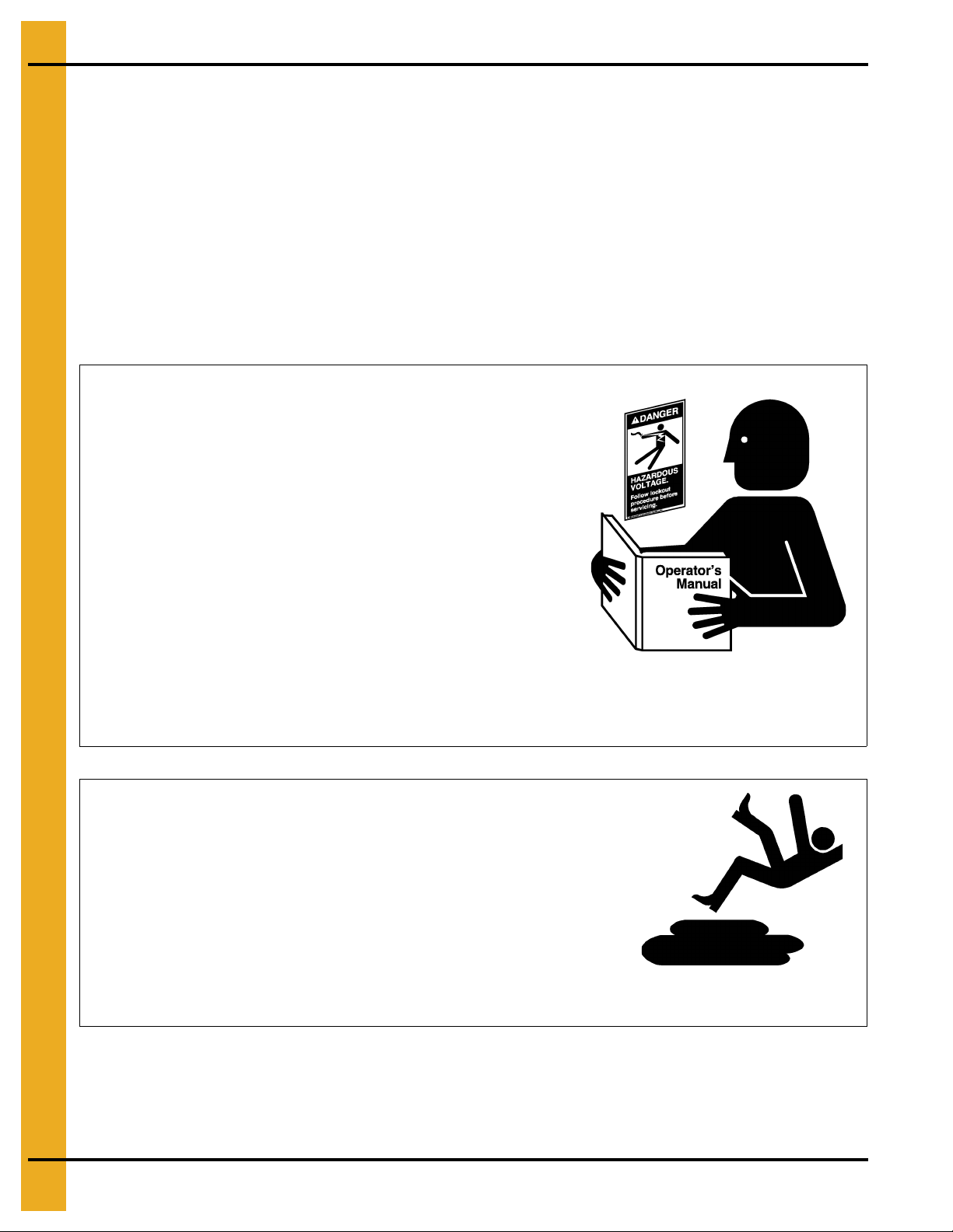
Follow Safety Instructions
Carefully read all safety messages in this manual and
safety signs on your machine. Keep signs in good
condition. Replace missing or damaged safety signs. Be
sure new equipment components and repair parts include
the current safety signs. Replacement safety signs are
available from the manufacturer.
Learn how to operate the machine and how to use controls
properly. Do not let anyone operate without instruction.
Keep your machinery in proper working condition.
Unauthorized modifications to the machine may impair
the function and/or safety and affect machine life.
If you do not understand any part of this manual or need
assistance, contact your dealer.
Read and Understand Manual
Practice Safe Maintenance
Understand service procedures before doing work. Keep area
clean and dry.
Never lubricate, service, or adjust machine while it is in operation.
Keep hands, feet, and clothing away from rotating parts.
Keep all parts in good condition and properly installed. Fix
damage immediately . Replace worn or broken p arts. Remove any
built-up grease, oil, and debris.
Maintain Equipment
and Work Area
Safety Instructions
Our foremost concern is your safety and the safety of others associated with this equipment. We want to
keep you as a customer. This manual is to help you understand safe operating procedures and some
problems that may be encountered by the operator and other personnel.
As owner and/or operator, it is your responsibility to know what requirements, hazards, and precautions
exist, and to inform all personnel associated with the equipment or in the area. Safety precautions may be
required from the personnel. Avoid any alterations to the equipment. Such alterations may p roduce a very
dangerous situation where SERIOUS INJURY or DEATH may occur.
This equipment shall be installed in accordance with the current installation codes and applicable
regulations, which should be carefully followed in all cases. Authorities having jurisdiction should be
consulted before installations are made.
8 PNEG-2400 CFL Commercial Farm 4" Corrugation Externally Stiffened Grain Bin
Page 9
1. Safety
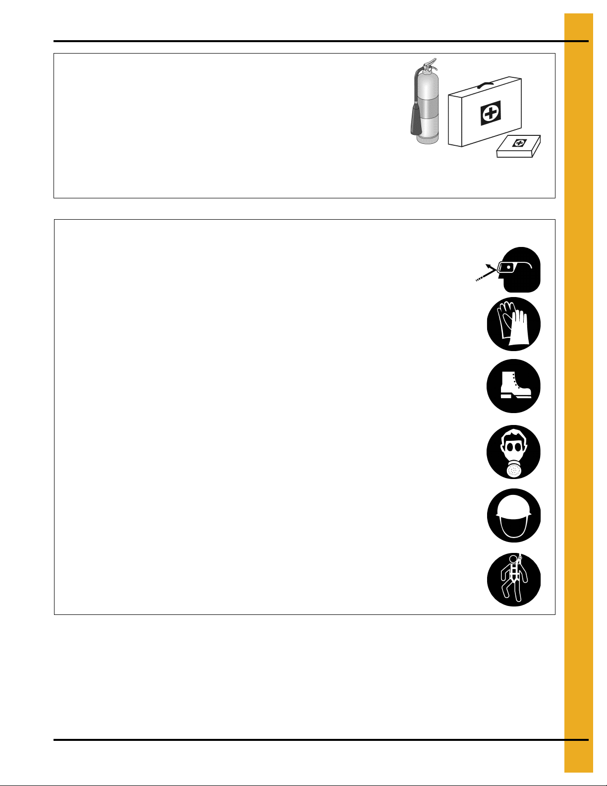
Prepare for Emergencies
Be prepared if fire starts.
Keep a first aid kit and fire extinguisher handy.
Keep emergency numbers for doctors, ambulance service,
hospital, and fire department near your telephone.
Keep Emergency Equipment
Quickly Accessible
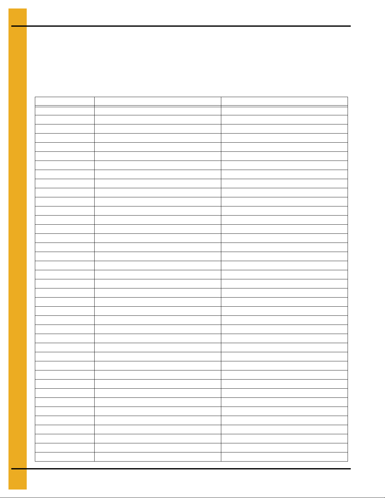
Wear Protective Clothing
Wear close-fitting clothing and safety equipment appropriate
to the job.
Remove all jewelry.
Tie long hair up and back.
Wear safety glasses at all times to protect eyes from debris.
Wear gloves to protect your hands from sharp edges on plastic
or steel parts.
Wear steel-toed boots to help protect your feet from falling
debris. Tuck in any loose or dangling shoestrings.
A respirator may be needed to prevent breathing potentially
toxic fumes and dust.
Wear a hard hat to help protect your head.
Wear appropriate fall protection equipment when working at
elevations greater than six feet (6').
Eye Protection
Gloves
Steel-Toed Boots
Respirator
Hard Hat
Fall Protection
PNEG-2400 CFL Commercial Farm 4" Corrugation Externally Stiffened Grain Bin 9
Page 10
1. Safety
Safety Sign-Off Sheet
As a requirement of O.S.H.A., it is necessary for the employer to train the employee in the safe operating
and safety procedures for this auger. This sign-off sheet is provided for your convenience and personal
record keeping. All unqualified persons are to stay out of the work area at all times. It is strongly
recommended that another qualified person who knows the shut down procedure be in the area in the
event of an emergency.
Date Employee Name Supervisor Name
10 PNEG-2400 CFL Commercial Farm 4" Corrugation Externally Stiffened Grain Bin
Page 11

1. Safety
Proper Storage of Grain Bin/Silo Materials Prior to Construction
Wet storage stain (rust) will develop when closely packed bundles of galvanized material, such as sidewall
and roof sheets, have moisture present. Inspect roof and sidewall bundles on arrival for any moisture. If
moisture is present, it must not be allowed to remain between the sheets. Separate the sheets or panels
immediately and wipe them down. Spray with a light oil or diesel fuel.
If possible, sidewall bundles, roof sheets and other closely packed galvanized materials should be stored
in a dry, climate controlled building. If outdoor storage is unavoidable, the materials should be stored so
that they are raised above the ground and vegetation. Any stacking and spacing materials should not be
corrosive or wet. Be sure to protect materials from the weather, but permit air movement around the
bundles if possible.
Storing roof bundles and sidewall sheets at a slight incline can also help minimize the presence of
moisture. Storing the bundles with the center of the dome up (like an arch) is one option for minimizing
moisture during storage. Sidewall bundles can also be stored on edge but must be secured so that they
do not fall over and cause injury.
If “white rust” or “wet storage stain” occurs, contact the manufacturer immediately about ways to minimize
the adverse effect upon the galvanized coating.
PNEG-2400 CFL Commercial Farm 4" Corrugation Externally Stiffened Grain Bin 11
Page 12
2. Decals
Excessive vacuum (or pressure) may
damage roof. Use positive aeration
system. Make sure all roof vents are
open and unobstructed. Start roof
fans when supply fans are started.
Do not operate when conditions exist
that may cause roof vent icing.
DC-969
CAUTION!
The manufacturer does not warrant an y roof damage caused by excessive vacuum or internal
pressure from fans or other air moving system s. Ade quate v entilation and/o r “make up air” dev ices
should be provided for all powered air handling systems. The manufacturer does not reco mmend
the use of downward flow systems (suction). Severe roof damage can result from any blockage of
air passages. Running fans during high humid ity/co ld w ea ther co nditio ns can ca us e air ex haust or
intake ports to freeze.
12 PNEG-2400 CFL Commercial Farm 4" Corrugation Externally Stiffened Grain Bin
Page 13
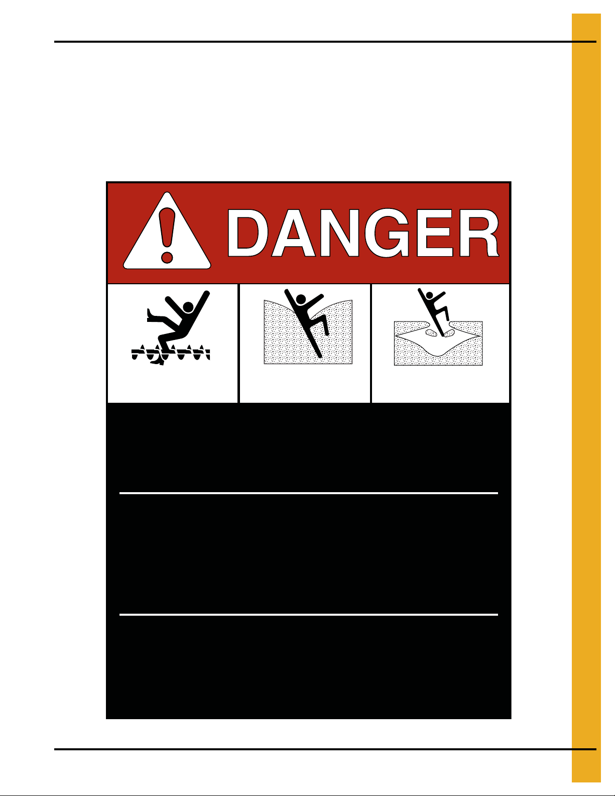
2. Decals
Rotating flighting will
kill or dismember.
Flowing material will
trap and suffocate.
Crusted material will
collapse and suffocate.
Keep clear of all augers.
DO NOT ENTER this bin!
Failure to heed these
warnings will result in
serious injury or death.
If you must enter the bin:
1. Shut off and lock out all power.
2. Use a safety harness and safety line.
3. Station another person outside the bin.
4. Avoid the center of the bin.
5. Wear proper breathing equipment or respirator.
DC-GBC-1A
ATTENTION: The decal shown below should be present on the inside of the outside door cover of the
2 ring, 24" porthole door cover and roof manway cover. If a decal has been damage d or is missing in any
of these locations, contact the manufacturer for a free replacement decal.
GSI Decals
1004 E. Illinois St.
Assumption, IL. 62510
Phone: 1-217-226-4421
PNEG-2400 CFL Commercial Farm 4" Corrugation Externally Stiffened Grain Bin 13
Page 14
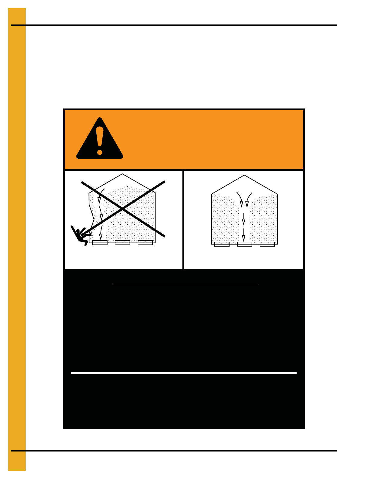
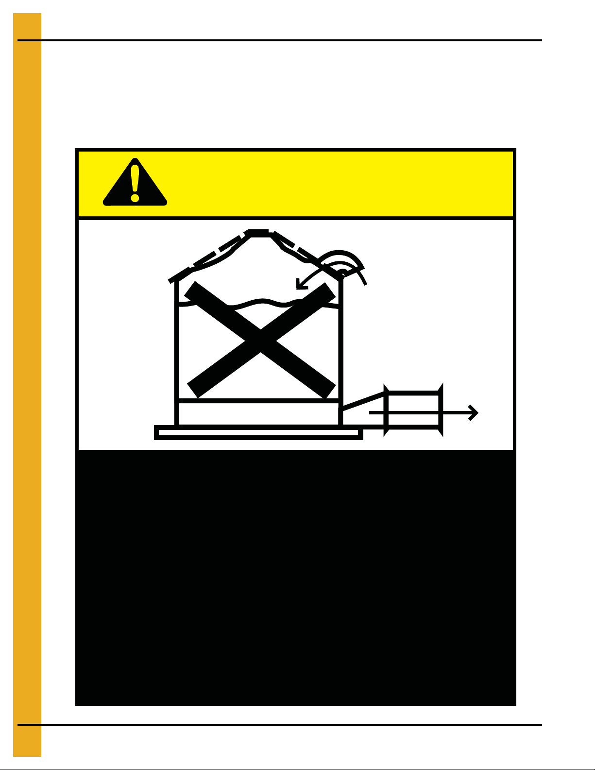
2. Decals
Failure to heed these warnings
could result in serious injury, death,
structural damage or collapse of tank.
1. Use CENTER FLOOR OUTLET ONLY until NO grain
remains above this outlet.
2. Side floor outlets to be used ONLY when above
condition is satisfied.
3. Lock all side floor outlets to avoid accidental
premature use.
4. See manufacturers instructions for proper use of
factory supplied sidedraw (wall) discharge systems.
UNLOADING INSTRUCTIONS:
DC-GBC-2A
WARNING
DON’T
DO
ATTENTION: The decal shown below should be present on the inside of the outside door cover of the
2 ring, 24" porthole door cover and roof manway cover. If a decal has been damaged or is missing in any
of these locations, contact the manufacturer for a free replacement decal.
GSI Decals
1004 E. Illinois St.
Assumption, IL. 62510
Phone: 1-217-226-4421
14 PNEG-2400 CFL Commercial Farm 4" Corrugation Externally Stiffened Grain Bin
Page 15

3. Bin Assembly
General Information
INSPECT the shipment immediately upon arrival. The customer is responsible for ensuring that all
quantities are correct. Report any damage or shortages by recording a detailed description on the bill of
lading to justify the customer’s claim from the transport firm. Our responsibility for damage to the
equipment ends with acceptance by the delivering carrier. Save all paperwork and documentation
furnished with any of the equipment/components.
This manual should be considered a permanent part of the equipment and should be easily accessible
when needed.
Read this manual carefully. This manual will provide instructions on building the sidewall. Other
instructions and manuals are required to build this tank. Some of the additional materials needed are
detailed below.
A stiffener and sidewall gauge layout chart is needed. If such a chart is not included with this
manual, contact GSI.
Roof instructions are required and must be followed. The roof construction manual (PNEG-1092) will
contain instructions for 60' diameter and smaller bins. See appropriate individual diameter instructions for
other diameters.
Review location of accessories and required placement.
Ladders, roof stairs, roof handrails and other products are covered by separate instruction manuals.
Consult the appropriate accessory manual.
Floor systems, aeration systems and transitions are to be installed according to the instructions provided
with the system or transition.
Refer to anchor bolt placement detail chart on Page 86.
Tools for construction:
• Combination wrench set 7/16" to 1".
• Alignment punches 12" long.
• Hammer.
• Screw drivers - standard and phillips.
• 3/8" Drive socket set and ratchet.
• 1/2" Drive socket set and ratchet.
• Nail aprons or tool pouches to hold supplies.
• Gloves for hand protection.
• Tape measure.
• 1/2" Drive electric or pneumatic impact gun.
• 1/2" Drive impact socket set.
• Lifting jacks.
• Center pole roof support.
• Step ladders.
• Large C-clamp or welding V-grip for clamping.
Quantities required depends on the number of workers and size of the bin/silo.
PNEG-2400 CFL Commercial Farm 4" Corrugation Externally Stiffened Grain Bin 15
Page 16

3. Bin Assembly
Construction Procedures and Lifting Jack Usage
NOTE: The roof and top ring or two (2) rings will be installed prior to the beginning of bin lifting/jacking
procedures. Refer to all other procedures on sidewall and stiffener installation prior to the
start of construction.
1. Consider the starting location of the bin, as it relates to the location of doors and other accessories.
Proper placement of lifting jacks in relationship to anchor bolts could influence final locations. Note
that the sidewall sheets will be staggered.
2. Lifting jacks are used to slowly and evenly lift the bin during construction. Lifting jacks must be
properly sized and designed to carry all dead and live loads and meet all job site conditions
associated with the construction of the bin.
The number of lifting jacks required is best determined by personal experience and expertise.
Factors such as bin size, jack design, construction conditions, support surface, etc., are all to be
considered when deciding how many to use. If in doubt, use one jack on every sheet. The lifting jack
must be adequate to carry all loads. Heavy duty jacks, generally hydraulic or electric powered in the
case of large bins, should be used for commercial installation. All jacks should be secured with
braces or otherwise maintained in a stable condition.
Do not lift bins under windy conditions.
Follow the jack manufacturer’s recommendations on capacity and operations.
3. Lifting brackets are often attached through the stiffener bolt holes. Normally at least four (4) bolts per
stiffener are required, however the proper number must be determination by the construction
supervisor. If lifting from horizontal sheet seams, ensure that lifting procedures an d attachments do
not damage the sidewall sheets.
4. Raise the bin just high enough to assemble the next ring. When lifting the bin, all jacks must lift at
an equal rate. Monitor the process to ensure that even lifting is occurring.
5. Bolt the next ring to the inside of the first ring. Be sure to stagger the sheets and select the prope r
gauge material.
6. After assembling and tightening the bolts on the new ring (or rings), lower the bin onto the foundation.
7. Attach stiffeners to the body sheets every two (2) tiers on the external surface of the bin. Consider
leaving the sheets loose to make the attachment of the stiffeners easier.
8. Re-bolt the lifting brackets to the lowest ring in place thus far. Continue ring additions by repeating
Step 5 and Step 6.
9. Add inside and outside ladders as you continue to raise the bin. (Refer to the manual supplied with
the ladder.)
10. Lower the tank and secure to the foundation before leaving the job site.
11. At the completion of the tank, set stiffeners over the anchor bolts and measure the tank to ensure it
is in a round condition. Consult with GSI for questions on tolerances.
NOTE: For 2 ring doors or vehicle traffic doors, special placement issues may apply. Consult the special
instructions provided with 2 ring doors or vehicle traffic doors for these options.
16 PNEG-2400 CFL Commercial Farm 4" Corrugation Externally Stiffened Grain Bin
Page 17
3. Bin Assembly
Sidewall Construction
Sidewall Construction Instructions
Gauge Color Code
1. Before bolting the sidewall sheets together, check for the proper gauge of steel for the first ring.
Sidewall sheet layout by gauge is stapled to front of manual provided with the shipped bin. If missing
contact GSI. Higher gauge numbers denote the thinner materials. (For example, 20 gauge material
is thinner than 14 gauge.)
2. In erecting most grain bins, the thinnest material usually goes on top, therefore the first sidewall ring
you assemble will be the top ring of the bin.
3. Check the various gauges of the bin with the color code chart and begin building accordingly.
REMEMBER assemble the top ring first.
4. Decal sheet will be installed in the second ring from the top.
Gauge Color Code
20 Red
19 Black/Yellow
18 Orange
17 Pink/Light Blue
16 Blue
15 Brown/Red
14 Green
13 Yellow/Blue
12 Black
11 Pink/Purple
10 Light Blue/Purple
9 Blue/Orange/Purple
8 Yellow/Purple
6 White/Purple
5 Fluorescent Green/Purple
Figure 3A
PNEG-2400 CFL Commercial Farm 4" Corrugation Externally Stiffened Grain Bin 17
Page 18
3. Bin Assembly
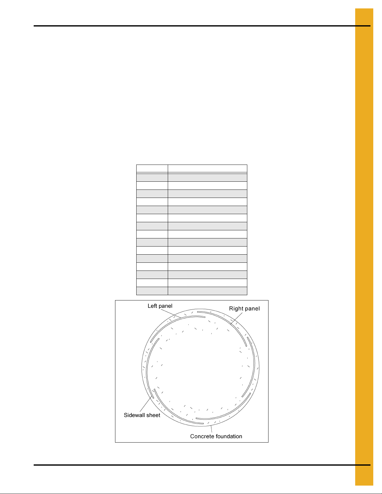
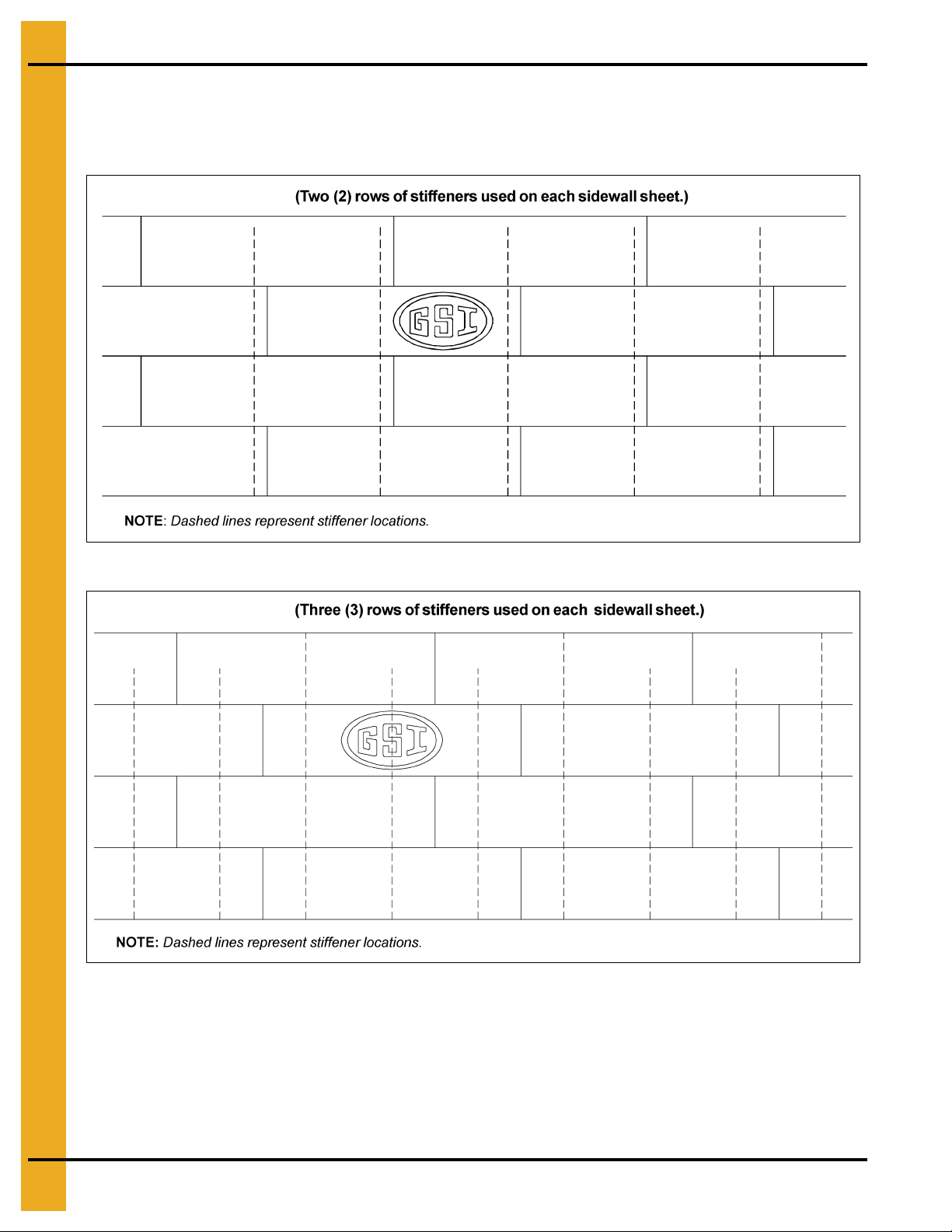
Decal Sheet Placement
NOTE: The decal sheets are located in the second ring from the top. They are to be sp aced evenly around
the diameter of the bin.
Figure 3B 2 Post
Figure 3C 3 Post
18 PNEG-2400 CFL Commercial Farm 4" Corrugation Externally Stiffened Grain Bin
Page 19
3. Bin Assembly
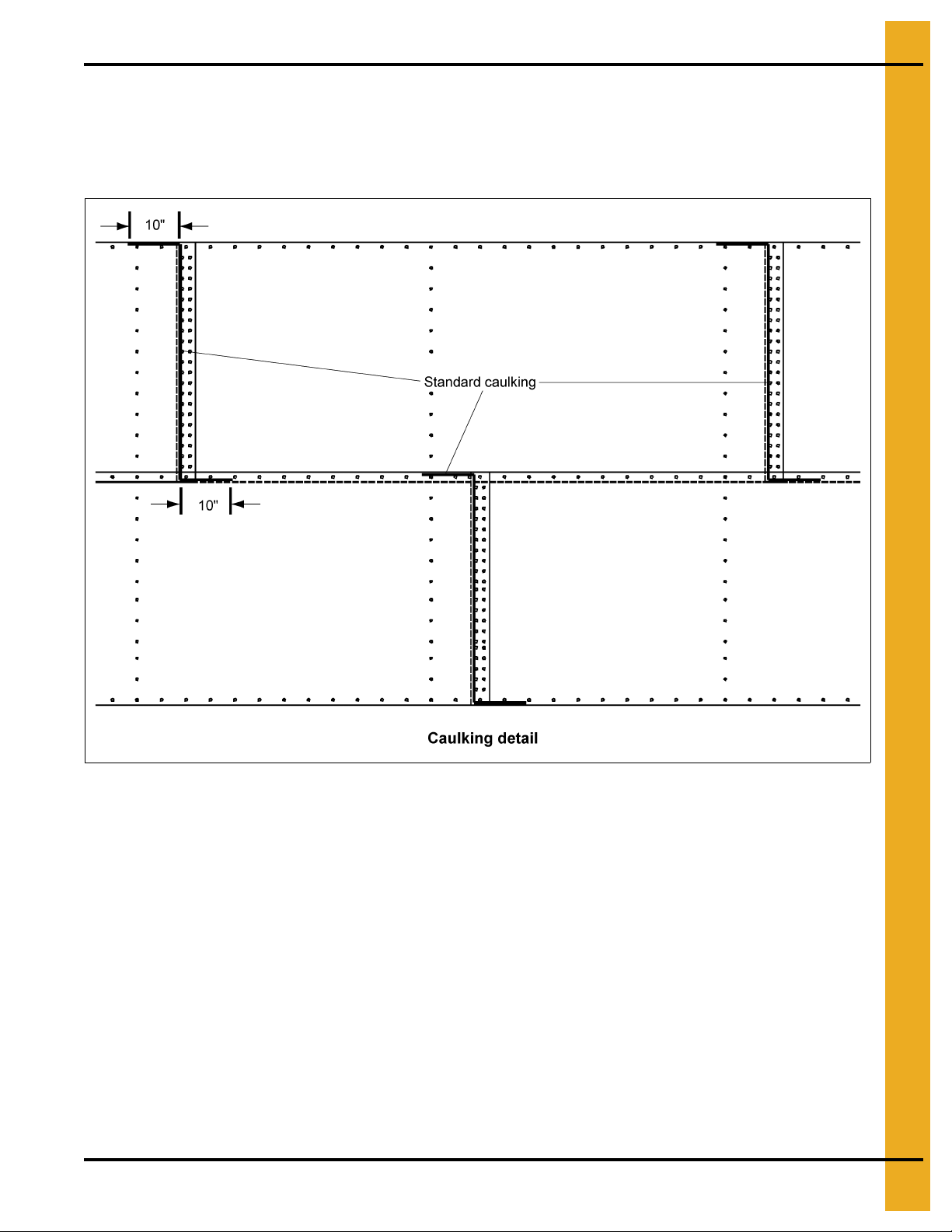
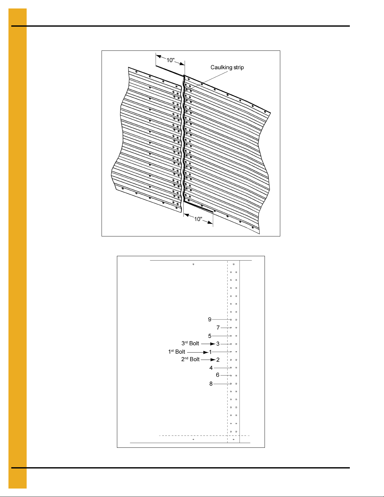
Caulking Detail
NOTE: The rope caulking is installed before each sheet is assembled. Apply rope caulking between the
last vertical row of bolts and edge of outside sheet. There is sufficient caulking for all vertical
seams on storage and drying bins. Wipe sheet clean where caulking is to be applied.
Figure 3D Standard Sidewall Sheets (As Viewed from Inside Bin.)
Apply one strip of caulking near the inside edge of the inner sheet. (See Figure 3D.) Place a 10" long
strip of caulking along the horizontal seams. Before bolting the next ring into place, apply a strip of
caulking 10" long on the front of the underlapped sheet at each joint. A 10" strip of caulking is also to be
placed along the lower horizontal edge of the lapping sheet at e very vertical seam. This will fill the space
that occurs between the holes caused by the overlapping sheets. Additional 10" strips of caulking must
be used to fill larger gaps that occur with heavier gauges or use non-reactive op aque caulk to fill gaps
at overlap.
PNEG-2400 CFL Commercial Farm 4" Corrugation Externally Stiffened Grain Bin 19
Page 20
3. Bin Assembly
Caulking Detail (Continued)
Figure 3E Viewed from the Inside of the Bin
Figure 3F Tighten Bolts in Order
20 PNEG-2400 CFL Commercial Farm 4" Corrugation Externally Stiffened Grain Bin
Page 21
3. Bin Assembly
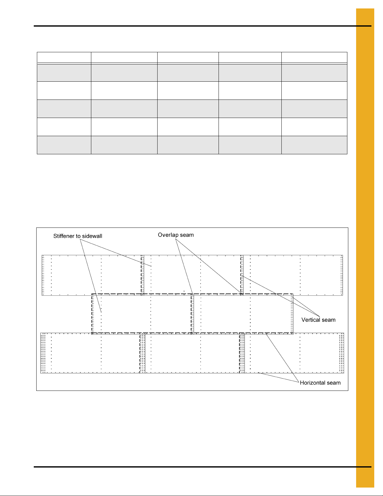
Bolting Requirements - 2 Stiffeners per Sidewall Sheet
Sidewall Gauge Horizontal Seam Vertical Seam Stiffener to Sidewall Overlap Seam
20-15
14-12
11-10
9-8
6-5
5/16" x 3/4" (S-275)
[8]
3/8" x 1" (S-455)
[20]
3/8" x 1" (S-455)
[20]
3/8" x 1" (S-455)
[20]
3/8" x 1-1/2" (S-5060)
[20]
5/16" x 3/4" (S-275)
[42]
3/8" x 1" (S-455)
[42]
3/8" x 1" (S-455)
[63]
3/8" x 1" (S-455)
[63]
3/8" x 1-1/2" (S-5060)
[63]
3/8" x 1" (S-455)
[22]
3/8" x 1" (S-455)
[22]
3/8" x 1" (S-455)
[22]
3/8" x 1-1/2" (S-5060)
[22]
3/8” x 1-1/2" (S-5060)
[22]
5/16" x 3/4" (S-275)
[2]
3/8" x 1" (S-455)
[2]
3/8" x 1" (S-455)
[2]
3/8" x 1-1/2" (S-5060)
[4]
3/8" x 1-1/2" (S-5060)
[4]
• Use 3/8" x 1-1/2" (S-5060) bin bolts at splice locations to attach the stiffener/splice plate to
the sidewall.
•
Use 3/8" x 1-1/2" (S-5060) bin bolts on laminated stiffeners to attach stiffeners to the sidewall sheet.
• Refer to Stiffener Assembly Details on Page 65 and the Caulking Detail on Pages 19 and 20 for
stiffener assembly hardware usage and caulking details. Refer to hardware identification section
on Page 50 for aid in hardware identification.
Figure 3G As Viewed from Outside
PNEG-2400 CFL Commercial Farm 4" Corrugation Externally Stiffened Grain Bin 21
Page 22
3. Bin Assembly
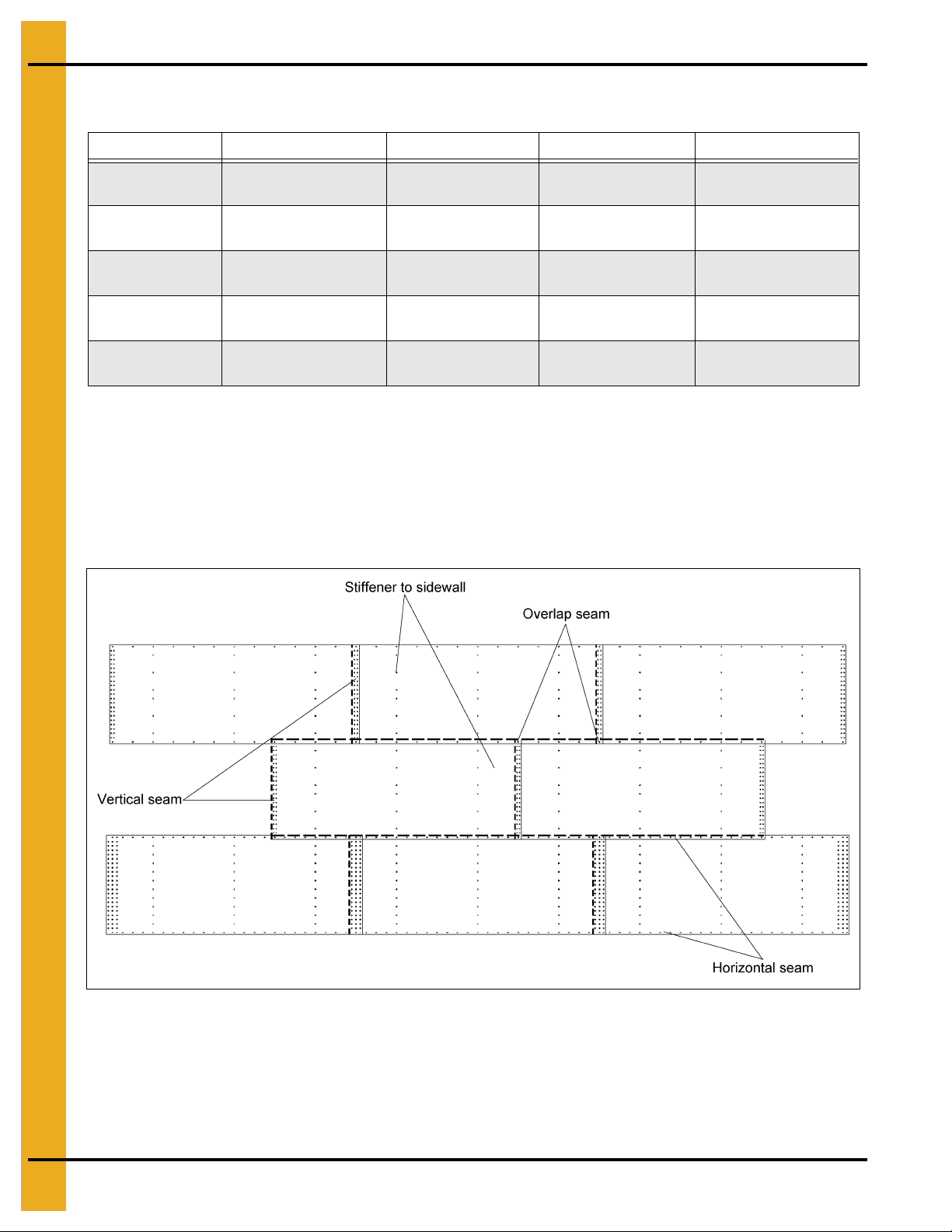
Bolting Requirements - 3 Stiffeners per Sidewall Sheet
Sidewall Gauge Horizontal Seam Vertical Seam Stiffener to Sidewall Overlap Seam
20-15
14-12
11-10
9-8
6-5
5/16" x 3/4" (S-275)
[8]
3/8" x 1" (S-455)
[20]
3/8" x 1" (S-455)
[19]
3/8" x 1" (S-455)
[20]
3/8" x 1-1/2" (S-5060)
[20]
5/16" x 3/4" (S-275)
[42]
3/8" x 1" (S-455)
[42]
3/8" x 1" (S-455)
[63]
3/8" x 1" (S-455)
[63]
3/8" x 1-1/2" (S-5060)
[63]
3/8" x 1" (S-455)
[21]
3/8" x 1" (S-455)
[21]
3/8" x 1" (S-455)
[33]
3/8" x 1-1/2" (S-5060)
[33]
3/8" x 1-1/2" (S-5060)
[33]
5/16" x 3/4" (S-275)
[2]
3/8" x 1" (S-455)
[2]
3/8" x 1" (S-455)
[2]
3/8" x 1-1/2" (S-5060)
[4]
3/8" x 1-1/2" (S-5060)
[4]
• Use 3/8" x 1-1/2" (S-5060) bin bolts at splice locations to attach the stiffener/splice plate to
the sidewall.
• Use 3/8" x 1-1/2" (S-5060) bin bolts on laminated stiffeners to attach stiffeners to the sidewall sheet.
• Refer to Stiffener Assembly Details on Page 65 and the Caulking Detail on Pages 19 and 20 for
stiffener assembly hardware usage and caulking details. Refer to hardware identification section
on Page 50 for aid in hardware identification.
Figure 3H As Viewed from Outside
22 PNEG-2400 CFL Commercial Farm 4" Corrugation Externally Stiffened Grain Bin
Page 23
3. Bin Assembly
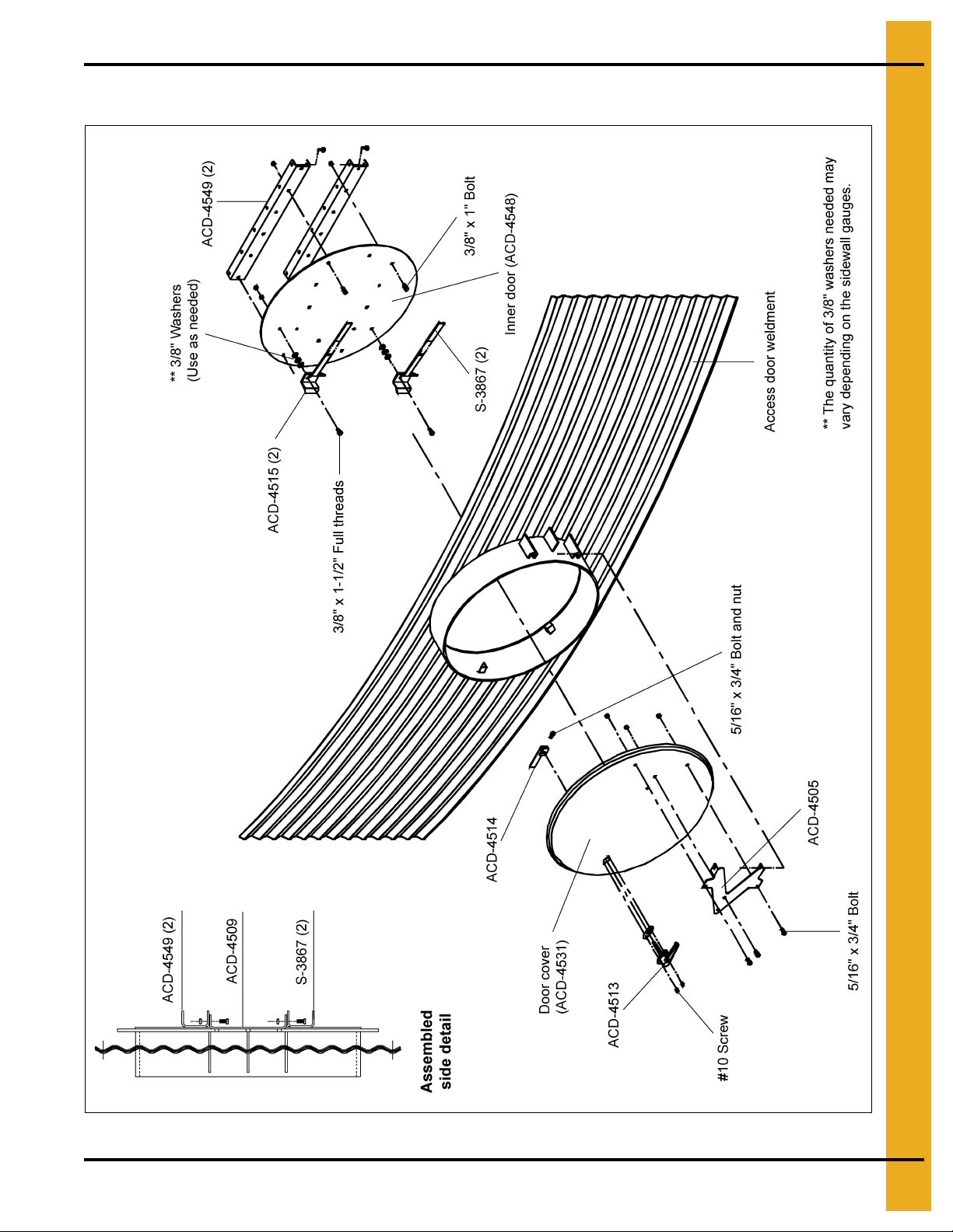
Access Door Weldment Assembly Hardware Package (PLS-41985)
Figure 3I
PNEG-2400 CFL Commercial Farm 4" Corrugation Externally Stiffened Grain Bin 23
Page 24
3. Bin Assembly
Notice for CFL 1 Ring Rectangular Door
This notice contains important information about the use of the CFL rectangular door manufactured for
4" corrugated tanks.
Important
This GSI CFL rectangular 1 ring door is designed for use in the 4" corrugation CFL series of tanks.
This door is intended for use with a tank specifically structured for the installation of the 1 ring door.
Special sidewall sheets are provided as part of the tank sidewall bundles. You must consult with GSI
concerning retrofitting into any existing GSI manufactured tank.
The door package NCWT0389 and NCWT0409 are designed for use in 16.5 m (54') - 23.5 m (60')
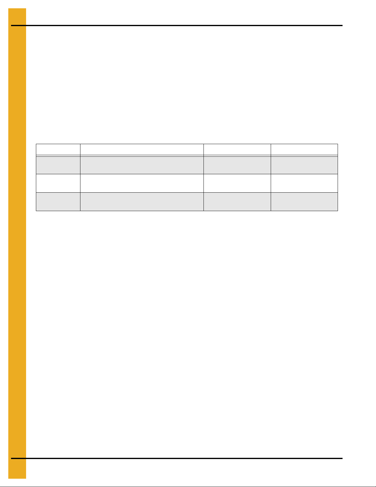
diameter tanks. See table below for eave heights.
Part # Description Diameter Range Maximum Eave Height
NCWT0389
NCWT0409
NCWT0409
Triple Punched CFL 1 Ring Rectangular
Inner/Outer Door Frame Package
Double Punched CFL 1 Ring Rectangular
Inner/Outer Door Frame Package
Double Punched CFL 1 Ring Rectangular
Inner/Outer Door Frame Package
16.5 m (54') -
18.3 m (60')
16.5 m (54')
15 Ring
18.3 m (60')
12 Ring
23.5 m (77'-2")
16.8 m (55'-2")
13.5 m (44'-2")
This door should not be installed in any GSI 2.66" corrugation series tank.
Consult with GSI concerning retrofitting into any existing GSI manufactured tank to determine compatibility
of the door package with the existing sidewall and stiffener configuration.
This door should not be installed in any tank not manufactured by GSI.
24 PNEG-2400 CFL Commercial Farm 4" Corrugation Externally Stiffened Grain Bin
Page 25
3. Bin Assembly
CFL 1 Ring Rectangular Door Hardware
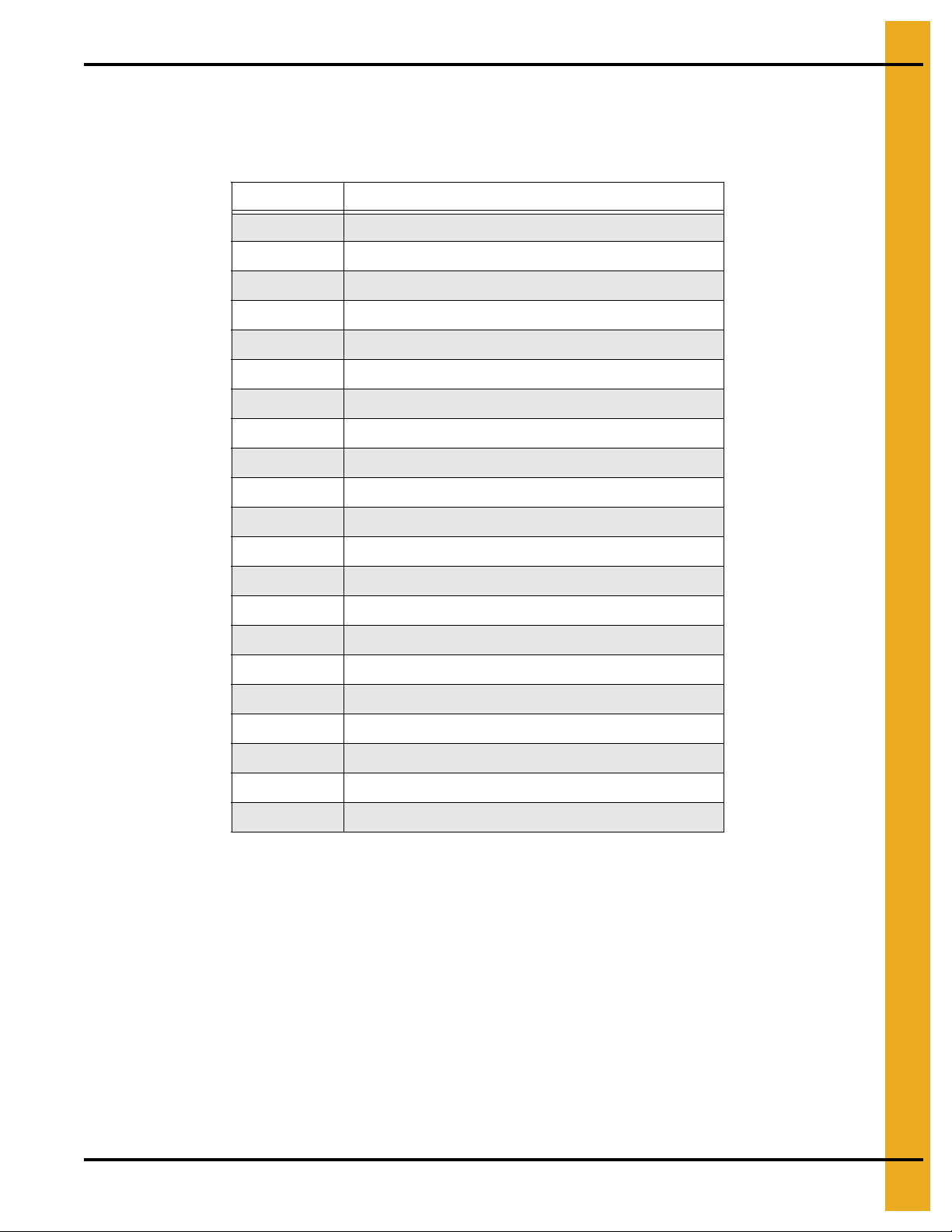
The following hardware list will be used during the installation of the 1 ring CFL door. Refer to below table
for hardware descriptions.
Part # Description
S-10202 CFL Double Punch Corrugation Spacer
S-2120 Flat Washer 1/2" SAE ZN
S-2739 Strip, 5 PC Box Poly-Base-Sealer - Five (5) Pieces
S-2741 Bolt, HHCS 5/16-18 x 1-1/2" ZN Grade 5
S-275 Bolt, HHBIN 5/16"-18 x 3/4" YDP Grade 5
S-277 Bolt, HHBIN 5/16-18 x 1-1/4 YDP Grade 5
S-3611 Flange Nut 5/16"-18 YDP Grade 2
S-3728 Bolt, HHTB 1/2"-13 x 1-1/2" YDP Grade 8 or Grade 8.2
S-396 Hex Nut 5/16-18 YDP Grade 2
S-4303 Truss Bolt 5/16"-18 x 3/4 YDP Grade 8 or Grade 8.2
S-4458 Sealant, Caulking 1/8" x 1/4" x 24'
S-455 Bolt, HHBIN 3/8-16 x 1 YDP Grade 8 or Grade 8.2
S-456 Hex Nut 3/8-16 YDP Grade 5
S-5220 Lock Nut 5/16-18 Grade 2
S-7248 Bolt, HHCS 3/8-16 x 6 ZN Grade 2
S-845 Flat Washer 5/16" USS SAE YDP Grade 2
S-8610 Strip, Foam Seal, 1/2" x1" x 25' 1 Roll
S-9373 Flange Nut 3/8"-16 YDP
S-9445 Bolt, HHBIN 3/8"-16 x 2" YDP Grade 8 or Grade 8.2
WD-6040 Bushing, Latch 2 Ring Door, Zinc Plated
WD-6224 Spacer, 0.812" Inside Panel Fastener
PNEG-2400 CFL Commercial Farm 4" Corrugation Externally Stiffened Grain Bin 25
Page 26

3. Bin Assembly
Installing Door Frame
You must install the door frame before any other door parts can be installed.
Before You Begin
1. Inner door frame should be placed inside bin before bin is constructed.
2. Obtain proper lifting equipment, punches and clamps.
3. You will need two (2) to three (3) people.
To Install the Door Frame
1. Using proper lifting equipment, lift both door frames (NCWT0381 and NCWT0380 for triple punched
frame, NCWT0408 and NCWT0407 for double punched frame) into position between the full sheet
and the short sheet located in the second ring from the bottom. (See Figure 3N on Page 29,
Figure 3O on Page 30 and Figure 3P on Page 31.)
NOTE: Caulk must be located around all bolt holes on both sides of the sidewall sheet before
the door frame is connected to the sidewall sheets. (See Figure 3J.) (See caulking details
on Page 27 and Page 28.)
Figure 3J Caulk Location (Caulk and foam sealant not shown for clarity.)
2. Align holes in the door frames with the holes in the sidewall sheets using punches. If needed, use
clamps to keep holes aligned. (See Figure 3Q on Page 32.)
26 PNEG-2400 CFL Commercial Farm 4" Corrugation Externally Stiffened Grain Bin
Page 27
3. Bin Assembly
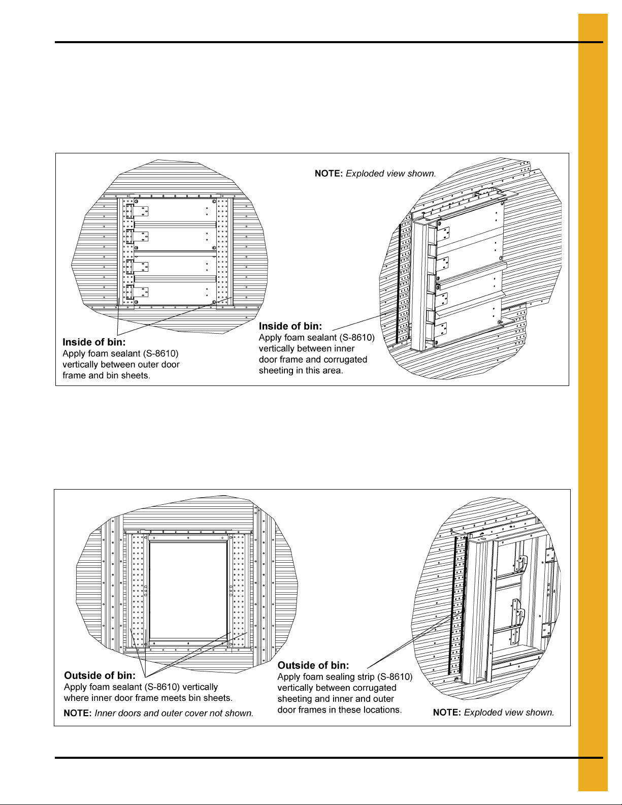
Sealing and Caulking Instructions
Inside of Bin
Apply vertical strip of foam sealant (S-8610) between inner door frame and corrugated sheeting as
shown in Figure 3K. Apply two (2) strips total, one on each side of door. Use rope caulk (S-4458) in
between foam sealant and corrugated sheeting.
Figure 3K
Outside of Bin
Apply vertical strips of foam sealant (S-8610) between outer door frame and corrugated sheeting as
shown in Figure 3L. Apply four (4) strips total, two (2) on each side of door. Use rope caulk (S-4458) in
between foam sealant and corrugated sheeting.
Figure 3L
PNEG-2400 CFL Commercial Farm 4" Corrugation Externally Stiffened Grain Bin 27
Page 28

3. Bin Assembly
Sealing and Caulking Instructions (Continued)
Outside Top and Bottom of Door
Apply foam sealant (S-8610) to the bottom of the upper sealing weldment (NCWT0383) as shown in
Figure 3M. Place the foam sealant around the perimeter of the surface of the sealing weldment as shown
in Figure 3M. Use rope caulk (S-4458) between the foam sealant and the upper door jam. After upper
sealing weldment is installed and bolted down, apply bead of caulk to joint between weldment and
corrugated sheeting as shown in Figure 3M.
Repeat steps above for bottom sealing weldment (NCWT0383).
Apply four (4) strips of foam sealant (S-8610) to outer cover (NCWT0387D) where cover contacts
door frame. (See Figure 3M.)
Figure 3M
28 PNEG-2400 CFL Commercial Farm 4" Corrugation Externally Stiffened Grain Bin
Page 29

Sidewall Layout
3. Bin Assembly
Figure 3N
PNEG-2400 CFL Commercial Farm 4" Corrugation Externally Stiffened Grain Bin 29
Page 30

3. Bin Assembly
Exploded Assembly View
Figure 3O
30 PNEG-2400 CFL Commercial Farm 4" Corrugation Externally Stiffened Grain Bin
Page 31

Exploded Assembly View (Continued)
3. Bin Assembly
Figure 3P
PNEG-2400 CFL Commercial Farm 4" Corrugation Externally Stiffened Grain Bin 31
Page 32

3. Bin Assembly
Figure 3Q Alignment Punches and Clamp
3. Install five (5) bolts along the top and bottom of the door frames connecting the inner and outer door
frames together using bolts (S-9445) and nuts (S-9373).
NOTE: Caulk along bolt connections between door frames.
4. To install side bolts for initial installation:
• For triple row punched door frames, locate bolts around door frame perimeter.
• For double row punched door frames, fill top, bottom and three (3) middle bolt hole locations.
NOTE: Install bolts (S-9445) and nuts (S-9373) to secure door frames to sidewall sheets only in
suggested locations, leaving holes open for the hinge housing brackets.
5. Locate and install the inner door hinge housing brackets (NCWT0386 for triple punched frame or
NCWT0406 for double punched frame) to the inner door frame as shown in Figure 3R on Page 33.
Tighten bracket bolts only finger tight to allow for future adjustment. (See Figure 3S on Page 34.)
32 PNEG-2400 CFL Commercial Farm 4" Corrugation Externally Stiffened Grain Bin
Page 33

Inner Panel Hinge Details
3. Bin Assembly
Figure 3R
PNEG-2400 CFL Commercial Farm 4" Corrugation Externally Stiffened Grain Bin 33
Page 34

3. Bin Assembly
Figure 3S Triple Punched Door Frame with Hinge Housing Bracket Locations
6. After hinge housing brackets are installed, fill all remaining door fra me holes with bolts (S-9445) and
tighten with nuts (S-9373).
34 PNEG-2400 CFL Commercial Farm 4" Corrugation Externally Stiffened Grain Bin
Page 35

3. Bin Assembly
Installing Inside Door Hinges
Door hinges go inside the door hinge housing brackets and allow the inner doors to open and close.
1. Insert tube of hinge (NCWT0377) inside the hinge housing bracket (NCWT0386), aligning the holes.
NOTE: Orientation of the hinge is critical for closure of the door, See Figure 3T for clarification.
2. Insert bolt (S-7248) through the holes in the hinge housing bracket (NCWT0386) and tube in the
hinge (NCWT0377).
3. Repeat for all hinges.
Figure 3T Installing Hinge
PNEG-2400 CFL Commercial Farm 4" Corrugation Externally Stiffened Grain Bin 35
Page 36

3. Bin Assembly
Attaching Inner Doors to Hinges
1. Using two (2) or more people, lift inner bottom do or (NCWT0378) aligning holes in door with holes in
hinges (NCWT0377). (See Figure 3U.)
2. Making sure bolt heads are towards the outside of the bin, insert bolts (S-277) through washer
(S-845), outer most holes in the hinges and fasten with nuts (S-396).
NOTE: Tighten bolts only finger tight.
3. Repeat for the inside bottom door.
Figure 3U Hinges Attached to Inner Door
Assembling Door Latch Bars
You can use the latch bars to open and close the inner doors.
1. Align reinforcement angles (NCWT0371) with the holes in the top inner door and hinges.
2. Making sure the bolt heads are towards the outside of the bin, insert bolts (S-275) through the holes
in the reinforcement brackets, top inner door and hinges then fasten loosely with a nut (S-396).
3. Install inside left (WD-6038) and right (WD-6037) panel latches to the reinforcement angles.
NOTE: Latches are located in the bottom holes for the top inner door and the top holes for the bottom
inner door. (See Figure 3V on Page 37 and Figure 3W on Page 38.)
4. Loosely fasten in place using bolts (S-277), latch bushings (WD-6040) and lock nuts (S-5220).
5. Install latch bars (NCWT0374) between the left and right panel latches using bolts (S-4303) and
nuts (S-3611).
6. Repeat for bottom inner door.
36 PNEG-2400 CFL Commercial Farm 4" Corrugation Externally Stiffened Grain Bin
Page 37

Bottom Inner Panel Assembly
3. Bin Assembly
Figure 3V
PNEG-2400 CFL Commercial Farm 4" Corrugation Externally Stiffened Grain Bin 37
Page 38

3. Bin Assembly
Top Inner Panel Assembly
Figure 3W
38 PNEG-2400 CFL Commercial Farm 4" Corrugation Externally Stiffened Grain Bin
Page 39

3. Bin Assembly
Installing Bearing Pins
The bearing pins help to align the inner doors and assure proper closure of the inner doors.
1. Locate eight (8) bearing pins (WD-6224) in the inner door frame as shown in Figure 3R o n Page 33.
2. Secure bearing pins to door frame using bolts (S-2741), washers (S-845) and nuts (S-3611).
Figure 3X
PNEG-2400 CFL Commercial Farm 4" Corrugation Externally Stiffened Grain Bin 39
Page 40

3. Bin Assembly
Installing Door Latch Holders
The four (4) door latch holders secure the latches in place and keep the top and bottom doors closed.
1. Install four (4) door latch holders (WD-6234) to inner door frame using bolts (S-3728) and washers
(S-2120). (See Figure 3Z on Page 41.)
2. Use washers to adjust the latch holders position to align with door latches.
Tip
Start with five (5) washers and adjust quantity as needed.
Figure 3Y Latch door holder using washers for spacing.
Adjusting Inner Doors
The top and bottom inner doors must be level before fully tightened.
1. Adjust both inner doors so the bearing pins are centered in the corner holes on the doors.
(See Figure 3AA on Page 42.)
2. Close both doors and raise the latch bar over the latch holders.
3. Ensure both doors are firmly seated against the inner door frame.
4. Tighten all hardware that was previously left loose for adjustments.
40 PNEG-2400 CFL Commercial Farm 4" Corrugation Externally Stiffened Grain Bin
Page 41

Inner Frame Weldment Details
3. Bin Assembly
Figure 3Z
PNEG-2400 CFL Commercial Farm 4" Corrugation Externally Stiffened Grain Bin 41
Page 42

3. Bin Assembly
Bearing Pin Hinge Details
Figure 3AA
42 PNEG-2400 CFL Commercial Farm 4" Corrugation Externally Stiffened Grain Bin
Page 43

3. Bin Assembly
Installing the Seal Weldments
The seal weldments are located along the top and bottom of the door frames and function as a barrier,
keeping weather from entering the bin and grain from exiting the bin.
1. Locate outside seal weldment (NCWT0383) along the top of the outer door frame weldment
(NCWT0380 for triple punched frame and NCWT0407 for double punched frame). Fasten to top
of outer door frame using bolts (S-277) and washers (S-10102). (See Figure 3O on Page 30,
Figure 3AE on Page 45 and Figure 3AF on Page 46.)
2. Locate inside side seal weldment (NCWT0436) along the top of the inner door frame weldment
(NCWT0381 for triple punched frame and NCWT0408 for double punched frame). Fasten to top of
inner door frame using bolts (S-277). (See Figure 3O on Page 30, Figure 3AE on Page 45 and
Figure 3AF on Page 46.)
3. Fasten both top seal weldments simultaneously to the sidewall sheet using bolts (S-3727) and
nuts (S-456).
4. Repeat Steps 1-4 on Page 40 for the bottoms of the inner and outer door frames.
Installing the Kick Plate
The kick plate gives a uniform surface for entering the bin and covers the gap between the inner and
outer doors.
To Install the Kick Plate
1. Standing at the outside of the bin looking into the door, place the kick plate (NCWT0376) into the
doorway with the wider side to the inside of the bin.
2. Place the front lip of the kick plate into the recess of the outer door frame. (See Figure 3AB.)
Figure 3AB Kick Plate in Recess of Outer Door Frame
PNEG-2400 CFL Commercial Farm 4" Corrugation Externally Stiffened Grain Bin 43
Page 44

3. Bin Assembly
3. Pull the kick plate rear lip down and around the bottom of the inner door frame. (See Figure 3AC.)
Figure 3AC Kick Plate Under Inner Door Frame
4. Pull the front lip of the kick plate up and over the recess of the outer door frame. (See Figure 3AD.)
Figure 3AD Kick Plate Over the Outer Door Frame
5. Fasten the kick plate to the inner and outer door frames with six (6) bolts (S-277).
44 PNEG-2400 CFL Commercial Farm 4" Corrugation Externally Stiffened Grain Bin
Page 45

Outer Frame Weldment Details
3. Bin Assembly
Figure 3AE
PNEG-2400 CFL Commercial Farm 4" Corrugation Externally Stiffened Grain Bin 45
Page 46

3. Bin Assembly
Assembled View
Figure 3AF
46 PNEG-2400 CFL Commercial Farm 4" Corrugation Externally Stiffened Grain Bin
Page 47

3. Bin Assembly
Assembling Outer Door Cover
The outer door cover allows access to the inner doors and acts as a weather barrier.
1. Locate door cover hinge brackets (NCWT0170) on the front of the outer door cover (NCWT0387D)
and the outer cover reinforcement channels (NCWT0388) on the back of the outer door cover.
NOTE: Only use two (2) bolts opposite of the hinge brackets when installing the outer cover
reinforcement channels to leave an opening for the door retaining brackets.
2. Simultaneously attach the door cover hinge brackets and the cover reinforcement channels to the
outer door cover using bolts (S-275) and nuts (S-396).
3. Attach door retaining brackets (WD-033) to the front of the outer door cover and the cover
reinforcement channels using bolts (S-277) and nuts (S-396).
4. Attach the latch plates (NCWT0166) to the outer cover seal angle (NCWT0373) using bolts
(S-275) and nuts (S-5220).
5. Ensure decals (DC-GBC-2A and DC-GBC-2S) are applied to outer door cover (NCWT0387D)
as shown in Figure 3AG on Page 48 and Figure 3AH on Page 49.
PNEG-2400 CFL Commercial Farm 4" Corrugation Externally Stiffened Grain Bin 47
Page 48

3. Bin Assembly
Outer Door Cover Assembly
Figure 3AG
48 PNEG-2400 CFL Commercial Farm 4" Corrugation Externally Stiffened Grain Bin
Page 49

Assembled Outer Door Cover
3. Bin Assembly
Figure 3AH
PNEG-2400 CFL Commercial Farm 4" Corrugation Externally Stiffened Grain Bin 49
Page 50

3. Bin Assembly
Grade 2 bolts are designated with a plain head.
NOTE: Grade 2 bolts are designated with a plain head.
Grade 5 bolts are designated by three (3) slash marks on the head.
Grade 8 bolts are designated by six (6) slash marks on the head.
Grade 8.2 bolts are designated by six (6) slash marks on the head in a
sunrise pattern.
CAUTION
Under no condition shall any other bolts be substituted for those supplied with
this bin.
Do not tighten bolts to exceed the torque specifications listed below.
Hardware
NOTE:
Bolt Size
Torque (Ft. Lbs.)
Minimum Maximum
5/16"-18 15 20
3/8"-16 35 42
7/16"-14 65 72
1/2"-13 95 105
All bolts should be tightened from the nut side. Refer to bolt Identification section
further information on identification of the bin hardware.
on Page 51
for
50 PNEG-2400 CFL Commercial Farm 4" Corrugation Externally Stiffened Grain Bin
Page 51

3. Bin Assembly
0.3125" x 0.750" Pre-assembled with a steel backed sealing washer.
This bolt is used to connect horizontal and vertical seams for 15 gauge and thinner sidewall sheets
to each other. It is also used in attaching roof panels to the top sidewall sheet and attaching roof
panels and flashing to the center collar.
0.3125" x 1.250" Pre-assembled with a steel backed sealing washer.
This bolt is primarily used to connect roof panels together where they overlap. It is also used at the
bottom of the flat bottomed bins to attach the base angle to the sidewall sheet.
Bolt Identification
Refer to 4" commercial tank bolting requirements for complete bolt usage on Page 21 and Page 22.
PNEG-2400 CFL Commercial Farm 4" Corrugation Externally Stiffened Grain Bin 51
Page 52

3. Bin Assembly
0.375" x 1.000" Pre-assembled with a steel backed sealing washer.
This bolt is used in horizontal and vertical seams for 14 gauge through 8 gauge sidewall
to attach the sheets to each other and horizontal seams in 6-5 gauge. It is also used to attach the
stiffener to the sidewall sheet for up to 10 gauge sidewall. It is not used to splice the stiffeners
together on the flanges where they connect to each other or the splice plates.
NOTE: 3/8" x 1-1/2" Bolts (S-5060) are provided for laminated stiffeners and splices.
0.375" x 1.500" Pre-assembled with a steel backed sealing washer.
This bolt is used in vertical seams of 6-5 gauge sidewall and overlap joints 9-8 gauge. It is also used
to bolt stiffeners to 9 gauge and thicker sidewalls. The stiffener usage is only to attach the stiffener
and the splice plate to the sidewall. A different bolt, without a sealing washer, is used where the
stiffener bolts to the splice plates. It is used to connect the stiffener to the sidewall at locations
where a splice plate is used to connect the stiffener and to connect laminated stiffeners to the
sidewall sheets.
Refer to 4" commercial tank bolting requirements for complete bolt usage on Page 21 and Page 22.
52 PNEG-2400 CFL Commercial Farm 4" Corrugation Externally Stiffened Grain Bin
Page 53

3. Bin Assembly
0.375" x 1.000" Hex flanged head without a plastic sealing washer.
This bolt is used to splice the stiffeners together on the flanges of 8 gauge and thinner stiffeners.
A flange nut is used on the nut side of the connection. They are also used on the roof rafter splices
for some commercial roof systems.
0.375" x 1.500" Hex flanged head without a plastic sealing washer.
This bolt is used to attach the flanges of the 5 gauge and 6 gauge stiffeners to the splice plates
and splice laminated stiffeners together. A flange nut is used on the nut side of the connection.
Refer to 4" commercial tank bolting requirements for complete bolt usage on Page 21 and Page 22.
NOTE: Bolts with sealing washers are pre-assembled.
PNEG-2400 CFL Commercial Farm 4" Corrugation Externally Stiffened Grain Bin 53
Page 54

3. Bin Assembly
Color Chart for Bin Hardware Bucket Lids
Part # Color Description
S-275 5/16" x 3/4" Bolt pre-assembled with a steel backed sealing washer
S-277 5/16" x 1-1/4" Bolt pre-assembled with a steel backed sealing washer
S-396 5/16" Hex nut
S-455 3/8" x 1" Bolt pre-assembled with a steel backed sealing washer
S-456 3/8" Hex nut
S-5060 3/8" x 1-1/2" Bolt pre-assembled with a steel backed sealing washer
S-7927 3/8" x 1" Hex flanged head bolt without
S-7928 3/8" x 1-1/2" Hex flanged head bolt without sealing washer
S-8479 7/16" Special recessed nuts
Dark Blue
Black
Red
Grey
Yellow
Orange
Light Green
Dark Brown
Light Brown
sealing washer
S-9373 3/8" Hex flanged nuts
S-9444 7/16" x 2-1/2" Bolt pre-assembled with a steel backed sealing washer
S-9445 3/8" x 2" Bolt pre-assembled with a steel backed sealing washer
S-10114 7/16" x 2" Bolt pre-assembled with a steel backed sealing washer
Dark Purple
Dark Green
Light Blue
Light Purple
54 PNEG-2400 CFL Commercial Farm 4" Corrugation Externally Stiffened Grain Bin
Page 55

4. 4" CFL Commercial Tank Stiffener Instructions
NOTICE
If shim plates are not used where required, the downward pressure of the stiffeners
will not be transferred directly to the foundation and bin failure could result.
4" CFL Corrugation CFL Commercial Stiffener Splice Details
CFL tank stiffeners will be mounted on the outside of the tank.
The non-offset stiffeners that splice with a splice plate, must not overlap. Contact GSI if overlapping is
observed during construction.
When installing bottom stiffeners, the stiffener with base plate attached may not rest on the foundation
(due to unlevel foundation, etc.). If this happens, use the shim plates that are pro vided to fill any openings
between the base plate and concrete.
Stiffener Color Code Chart
NOTE: Some colors are different than those used for sidewall sheets.
Stiffener Gauge Color Code
15 Red
14 Green
13 Dark Blue
12 Black
11 Pink
10 Light Blue
9 Purple
8Yellow
6 White
5 Fluorescent Green
5+12 Gold/Black
5+10 Gold/Light Blue
5+8 Gold/Yellow
5+5 Gold/White
Special Sidewall Color Codes
One ring stiffeners: Orange strip added.
Transition stiffeners: Light blue strip added.
PNEG-2400 CFL Commercial Farm 4" Corrugation Externally Stiffened Grain Bin 55
Page 56

4. 4" CFL Commercial Tank Stiffener Instructions
2.66 Commercial Tank Stiffener Instructions Inside Stiffened Only
Universal Stiffener and Splice Hardware
Stiffeners Splicing Systems
12 Gauge to 12 Gauge
and Thinner
12 Gauge to 11 Gauge
through
8 Gauge to 5 Gauge, 6 Gauge
5 Gauge, 6 Gauge to 5 Gauge, 6 Gauge
5 Gauge to Laminated
Laminated to Laminated
Offset/Lapped Stiffener
No Separate Splices Plate
Use SWS-4829 Splice
Color Code: Light Blue
Use SWS-4829 Splice
Color Code: Light Blue
Use SWS-4957 Splice 2 per Joint
Splice Hardware Usage
(Not Including Sidewall to Splice Bolts)
Stiffeners Splicing Systems Hardware Part # Description Qty
14 Gauge and 15 Gauge Offset Stif fener Joint
12 Gauge and 13 Gauge Offset Stif fener Joint
10 Gauge and 11 Gauge
SWS-4829
Stiffener Joint
S-7927 3/8" x 1" 8
S-9373 3/8" Flange Nuts 8
S-7927 3/8" x 1" 8
S-9373 3/8" Flange Nuts 8
S-7927 3/8" x 1" 16
S-9373 3/8" Flange Nuts 16
8 Gauge and 9 Gauge
5 Gauge and 6 Gauge
Laminated
SWS-4829
Stiffener Joint
SWS-4829
Stiffener Joint
SWS-4957
Stiffener Joint
S-7927 3/8" x 1" 16
S-9373 3/8" Flange Nuts 16
S-7928 3/8" x 1-1/2" 16
S-9373 3/8" Flange Nuts 16
S-7928 3/8" x 1-1/2" 24
S-9373 3/8" Flange Nuts 24
Stiffener to Sidewall Hardware Usage
Splicing Systems Hardware Part # Description
Stiffener to Sidewall
SWS-4829
Splice to Sidewall
Laminated Stiffener to Sidewall
S-455 3/8" x 1"
S-456 3/8" Nuts
S-5060 3/8" x 1-1/2"
S-456 3/8" Nuts
S-5060 3/8" x 1-1/2"
S-9373 3/8" Flange Nuts
56 PNEG-2400 CFL Commercial Farm 4" Corrugation Externally Stiffened Grain Bin
Page 57

4. 4" CFL Commercial Tank Stiffener Instructions
Commercial Stiffeners for 4" Corrugation
Figure 4A
PNEG-2400 CFL Commercial Farm 4" Corrugation Externally Stiffened Grain Bin 57
Page 58

4. 4" CFL Commercial Tank Stiffener Instructions
Stiffener Splice Details
Figure 4B Standard Offset Stiffener Connection Detail
58 PNEG-2400 CFL Commercial Farm 4" Corrugation Externally Stiffened Grain Bin
Page 59

Offset to Transition Details
4. 4" CFL Commercial Tank Stiffener Instructions
Figure 4C
PNEG-2400 CFL Commercial Farm 4" Corrugation Externally Stiffened Grain Bin 59
Page 60

4. 4" CFL Commercial Tank Stiffener Instructions
Transition to 8 Gauge-11 Gauge Detail
Figure 4D
60 PNEG-2400 CFL Commercial Farm 4" Corrugation Externally Stiffened Grain Bin
Page 61

4. 4" CFL Commercial Tank Stiffener Instructions
Stiffener Splice Detail for 8 Gauge to 11 Gauge Stiffener
Figure 4E Standard Stiffener Splice Detail for 8 Gauge to 11 Gauge Stiffener
PNEG-2400 CFL Commercial Farm 4" Corrugation Externally Stiffened Grain Bin 61
Page 62

4. 4" CFL Commercial Tank Stiffener Instructions
6 Gauge to 5 Gauge Splice Connection
Figure 4F 6 Gauge to 5 Gauge Splice Connection
62 PNEG-2400 CFL Commercial Farm 4" Corrugation Externally Stiffened Grain Bin
Page 63

4. 4" CFL Commercial Tank Stiffener Instructions
5 Gauge to Laminated Stiffener Detail
Figure 4G
PNEG-2400 CFL Commercial Farm 4" Corrugation Externally Stiffened Grain Bin 63
Page 64

4. 4" CFL Commercial Tank Stiffener Instructions
Laminated Stiffener Splice
Figure 4H
64 PNEG-2400 CFL Commercial Farm 4" Corrugation Externally Stiffened Grain Bin
Page 65

4. 4" CFL Commercial Tank Stiffener Instructions
NOTE: See Hardware Usage Chart
on Page 50 for proper bolt usage.
Stiffeners to Sidewall Sheet Details
PNEG-2400 CFL Commercial Farm 4" Corrugation Externally Stiffened Grain Bin 65
Figure 4I
Page 66

4. 4" CFL Commercial Tank Stiffener Instructions
NOTE: See Hardware Usage Chart
on Page 50 for proper bolt usage.
Figure 4J
66 PNEG-2400 CFL Commercial Farm 4" Corrugation Externally Stiffened Grain Bin
Page 67

4. 4" CFL Commercial Tank Stiffener Instructions
Figure 4K
PNEG-2400 CFL Commercial Farm 4" Corrugation Externally Stiffened Grain Bin 67
Page 68

4. 4" CFL Commercial Tank Stiffener Instructions
Figure 4L
68 PNEG-2400 CFL Commercial Farm 4" Corrugation Externally Stiffened Grain Bin
Page 69

Wind Ring Assembly
5. Wind Ring Assembly Instructions
Figure 5A
1. To connect wind ring pipe to the stiffeners, attach with 3/8" x 1" bolts through the flange of the
stiffener. Field drilling of wind ring locations may be required in some cases.
2. Attach wind ring pipe section to stiffener using two (2) 3/8" x 6" (S-7248) wind ring clamps.
3. Place pipes end to end without overlapping. Fasten together using two (2) wind ring couplers
and six (6) 3/8" x 1" flanged head bolts with flanged nuts. Couplers should be centered on the
seam of pipes.
Figure 5B
PNEG-2400 CFL Commercial Farm 4" Corrugation Externally Stiffened Grain Bin 69
Page 70

6. Anchorage and Base Angle Instructions
NOTE: This is a minimum requirement for anchorage on standard tanks. Refer to Sidedraw Instructions on Page 72 for
special anchorage details. (1" Diameter required.)
Anchor Bolt Details
Figure 6A Anchor Bolt Detail
Anchor Bolt Washer Installation
Figure 6B
70 PNEG-2400 CFL Commercial Farm 4" Corrugation Externally Stiffened Grain Bin
Page 71

6. Anchorage and Base Angle Instructions
Base Angle Installation
On the lower edge of the final bottom ring, attach the base angle ring using 5/16" x 1-1/4" bin bolts. Before
the bolts are tightened, push the angle tight against the bottom edge of the sheet.
If the optional GSI base sealer strip is being used, before lowering the bin, apply the optional base sealer
to the entire underneath side of the base angle. (See Figure 6C.) Next, lower the bin onto th e foundation
and check for an adequate seal and supplemental sealing provided as needed.
The bin is to be sealed to the concrete foundation against water infiltration. If base sealer strip is not used,
another method should be used to seal the base ring to the concrete.
Figure 6C
PNEG-2400 CFL Commercial Farm 4" Corrugation Externally Stiffened Grain Bin 71
Page 72

7. Sidedraw Accessory Instructions
Installation and Management of Sidedraw Systems
GSI designs and manufacturers bins to the highest standards, however proper installation and good usage
practices for a commercial flume system are essential, regardless of manufacturer. The following practices
address general usage and installation criteria for such systems.
Sidedraw Installation
1. Side discharge is only permitted in GSI commercial bins when a GSI manufactured sidedraw flume
system has been installed. No corrugated steel bin should be unload ed through the sidewall without
installation of such a system and permission of the manufacturer.
Installation of a flume system requires installation of additional wind rings and 1" diameter anchor
2.
bolts. Refer to tank gauge sheet for wind ring placement or contact GSI.
for 1" anchor bolt usage.
Installation of multiple systems requires additional wind rings beyond the requirements for a single
system and must be placed a minimum of 90° apart. Installation of multiple systems requires
approval of GSI.
Reference the provided gauge sheet for wind ring placement.
Refer to Chart on Page 73
3. A sidedraw should not be the only discharge system available. A standard center discharge and
conveyor should be installed.
4. The standard sidedraw discharge location is shown on Page 76. For any other location consult GSI.
Sidedraw Management and Usage
1. Sidedraw systems are intended for use with dry flowable grain. Sidedraws are not to be used for
poorly flowing products. This is not unique to GSI bins and flume systems but is a general rule for
such systems.
2. In multiple system installations, only one sidedraw may be used at any one time.
3. Filling should not be occurring at the same time as grain is being withdrawn through the sidedraw
flume system.
4. Prolonged storage of grain in the sloped condition produced by sidedraw discharge may accelerate
differential settlement and result in deformations of the bin/silo. After using the sidedraw system, the
sloped grain should be returned to a near level condition by use of the center discharge. Leveling of
the grain should also allow more even consolidation of foundation and fill soils and produce more
even settlement of the bin/silo.
5. If geotechnical investigations or past experience indicate significant foundation level soil variations
or a site propensity toward differential settlement, sidedraw usage may be prohibited or severely
restricted. In this situation the use of a flume system should be reviewed with geotechnical
consultants or the foundation engineer.
72 PNEG-2400 CFL Commercial Farm 4" Corrugation Externally Stiffened Grain Bin
Page 73

7. Sidedraw Accessory Instructions
1" Diameter Anchor Bolt Requirements for Sidedraw Systems
1" Diameter Anchor Bolt Requirements for Sidedraw Systems Installed in
CFL - 4" Corrugation Commercial Tanks
2 Post Tanks (2 Stiffener per Sidewall Sheet)
Nominal Tank Diameter Total Number of Anchors
54 36
60 40
3 Post Tanks (3 Stiffener per Sidewall Sheet)
Nominal Tank Diameter Total Number of Anchors
54 54
60 60
Sidedraw System Installation
Wind Ring Installation
1. Sidedraw systems may require additional wind rings. They will need to be attached at the
beginning of assembly because they go on the upper most rings. (See wind ring requirements chart
on Pages 74 and 75.)
2. Attach the wind ring pipe to the stiffeners using 3/8" x 1" bolts through the flange of the stiffener.
(See Figure 7A.) In some cases field drilling of wind ring locations may be required.
3. Attach wind ring pipe section to the stiffener using two (2) 3/8" x 6" (S-7248) wind ring clamps.
(See Figure 7A.)
4. Place pipes end to end without overlapping. Fasten together using two (2) wind ring couplers and
six (6) 3/8" x 1" flanged head bolts with nuts. Couplers should be centered on the seam of pipes.
(See Figure 7A.)
Figure 7A
PNEG-2400 CFL Commercial Farm 4" Corrugation Externally Stiffened Grain Bin 73
Page 74

7. Sidedraw Accessory Instructions
Figure 7B
Wind Rings Sidedraw Usage - CFL 2 Post Stiffened Tanks
Additional Wind Rings for Sidedraw Usage with 2011 Series CFL 2 Post
Stiffened Tanks
This chart for use with a single sidedraw system at standard 5th ring from bottom discharge location.
Rings
21 4 1 4 1 21
20 3 2 4 1 20
19 3 2 3 2 19
18 2 3 3 2 18
17 2 2 3 1 17
16 2 2 3 1 16
15 2 1 3 1 15
14 2 1 2 2 14
13 2 1 2 2 13
54' 60'
Rings
Std Add Std Add
12 1 2 1 2 12
Use the above Chart for the quantity of wind rings to install with one standard sidedraw system at the
standard discharge location in a CFL 2 post per sidewall (Example: CFL54-19O) tank. Placement of wind
rings will be shown on the gauge sheet stapled to the front of this manual.
For wind ring quantity to be installed with two (2) standard systems, reference the cha rt for two (2) systems.
For special locations or greater than two (2) systems, consult with GSI.
74 PNEG-2400 CFL Commercial Farm 4" Corrugation Externally Stiffened Grain Bin
Page 75

7. Sidedraw Accessory Instructions
Additional Wind Rings for Sidedraw Usage with 2011 Series CFL 2 Post
Stiffened Tanks
This chart for use with two (2) sidedraw systems at standard 5th ring from bottom discharge location.
54' 60'
Rings
Std Add Std Add
21 4 3 4 3 21
20 3 3 4 3 20
19 3 3 3 3 19
18 2 4 3 3 18
17 2 3 3 2 17
16 2 3 3 2 16
15 2 2 3 2 15
14 2 2 2 2 14
Rings
13 2 2 2 2 13
12 1 2 2 2 12
Use the above Chart for the quantity of wind to rings install with two (2) standard sidedraw systems at the
standard discharge location in a CFL 2 post per sidewall (Example: CFL54-19O) tank. Placemen t of wind
rings will be shown on the gauge sheet stapled to the front of this manual.
For special locations or greater than two (2) systems, consult with GSI.
PNEG-2400 CFL Commercial Farm 4" Corrugation Externally Stiffened Grain Bin 75
Page 76

7. Sidedraw Accessory Instructions
See Figure 7E
on Page 77.
See Figure 7D
on Page 77.
Sidedraw System Installation
4"/WC Sidedraw Chute Installation
Number of Rings Starting Dimension Number of Chutes Horizontal Location for First Chute
21 54 21 Center between Stiffener
20 42 20 Center between Stiffener
19 62 18 Center between Stiffener
18 50 17 Center between Stiffener
17 38 16 Center between Stiffener
16 58 14 Center between Stiffener
15 46 13 Center between Stiffener
14 34 12 Center between Stiffener
13 54 10 Center between Stiffener
12 42 9 Center between Stiffener
Figure 7C Viewed from Inside Tank (2 Post Tank Shown)
76 PNEG-2400 CFL Commercial Farm 4" Corrugation Externally Stiffened Grain Bin
Page 77

7. Sidedraw Accessory Instructions
Sidedraw System Installation (Continued)
Locating Chutes
1. Starting from the first row of holes in the top sheet, measure down the “starting distance” for the bin.
(See Sidedraw Chute Chart on Page 76.) (See Figure 7C on Page 76 and Figure 7D below.)
2. Keep adding the required number of chutes, making sure to leave 8" between the chute bolt holes.
(See Figure 7C on Page 76.)
3. Stagger the sidewall sheets on three (3) post stiffened tanks to create a vertical strip between
stiffeners free of vertical seams. Install the chutes between the stiffeners in this area.
Locate Discharge Opening
1. The last bolt hole in the chute should line up with the center of the discharge chute opening tha t is to
be cut. (See Figure 7E.) Approximate an opening by measuring 9-1/2" above and below the last bolt
hole of the chute. Mark horizontal cut lines.
2. To find the vertical center of the chute opening, measure over 11" to the right and left of the chute
bolt rows. Mark center point. (See Figure 7E.) Measure 7" from the center point on both sides and
mark vertical cut lines.
3. Cut opening where marked, making sure corners have a minimum of 1-1/2" radius. (See Figure 7E.)
Figure 7D Figure 7E
PNEG-2400 CFL Commercial Farm 4" Corrugation Externally Stiffened Grain Bin 77
Page 78

7. Sidedraw Accessory Instructions
Sidedraw System Installation (Continued)
Sidewall Overlap
1. For proper watershed, make sure that the upper side sheet overlaps on top of the sidedraw
weldment. (See Figure 7F.)
Figure 7F
Caulking
1. To seal the sidedraw weldment to the sidewall sheets use: two (2) beads of caulking, one bead of caulk
on each side of the outside row of vertical bolts. Use discharge tube weldment as a template to field
drill the bolt holes through sidewall sheet. Use 3/8" bolts and nuts provide d to b olt s hee ts toge ther.
(See Figure 7G and Figure 7H.)
Use supplemental caulk as necessary for sealing purposes.
Figure 7G
78 PNEG-2400 CFL Commercial Farm 4" Corrugation Externally Stiffened Grain Bin
Figure 7H
Page 79

8. Accessory Instructions
Weather Cover Assembly
Weather Cover Assembly Instructions for Roller Valve
1. Install weather cover kit after gate has been installed.
2. Use bead caulking at all seams where weather cover attaches to gate.
3. Use 5/8" x 3/4" bolts and nuts to plug all holes not in use.
4. Use 1/4" self-drillers to seal gate end plate corners.
Figure 8A
PNEG-2400 CFL Commercial Farm 4" Corrugation Externally Stiffened Grain Bin 79
Page 80

9. Aeration Transition Instructions
At aeration duct entrances, the stiffener must be supported by a support post the supports the stiffener
column through the transition or by a adequately designed beam. See the following details.
Installation information on using GSI’s support post for 13-1/2" deep aeration entrance notch follows. For
other heights of transitions or entrance duct depths the stiffener must be su pported in a similar manner by
a column of adequate strength.
Reference aeration transition instructions for details on aeration transition assembly and installation.
Post Support Installation (TR-7140) for 13-1/2" Entrance Notch
1. Install the TR-7140 post support (TR-7140) as shown in the following instructions. (See Figure 9A.)
Figure 9A
2. Temporarily install the base stiffener and align the slots in the top plate of the post support with
the slots in the base plate on the base stiffener. Mark the duct top/bottom plates as shown in
Figure 9B and pre-drill for anchor bolt. (Base stiffener cannot be installed until TR-7140 installation
is complete.)
Figure 9B
80 PNEG-2400 CFL Commercial Farm 4" Corrugation Externally Stiffened Grain Bin
Page 81

9. Aeration T ransition Instructions
Figure 9C Transition Entrance Duct Cross Sections
PNEG-2400 CFL Commercial Farm 4" Corrugation Externally Stiffened Grain Bin 81
Page 82

9. Aeration Transition Instructions
3. Once the anchor bolt is installed, place the duct bottom plate and install the TR-7140 weldment
through the anchor bolt. Replace the duct top plate and attach the base stiffener to t he post support
as shown in Figure 9D. Secure using standard nuts and square washers.
Figure 9D
4. When possible fan transitions for full floor systems should be selected that will fit between the
stiffeners. If a transition that has a width that will not fit between the transition, the stiffener must
continue through the transition. Under no conditions may the stiffener be cut off. See the
TR-7067 seal kit instructions on Page 83 regarding a method to help seal around the stiffener when
it passes through a transition.
82 PNEG-2400 CFL Commercial Farm 4" Corrugation Externally Stiffened Grain Bin
Page 83

9. Aeration T ransition Instructions
Universal Stiffener Seal Kit
Seal Kit (TR-7067) (Optional)
Air deflector included in seal kit (TR-7067) may be installed over stiffener at customer’s request.
An access hole must be cut for the stiffener in bottom of the transition housing. Cut a 9" x 6" hole in the
bottom center of the transition before attaching the transition to the bin. Attach transition to sid ewall sheet
as shown in Figure 9E. Field drill 3/8" stiffener holes through transition entrance collar. A hole must now
be cut in the top center of the transition. Mark a 9" wide x 6" opening for the stiffener to enter. Cut along
the line. Bottom edge of entrance collar will also need to be trimmed to provide clear access for stiffener.
Place stiffener through transition housing and attach to sidewall. Be sure stiffener anchor is located on
anchor bolt. Place washer and nut on anchor bolt and tighten.
Stiffener transition cover plates are supplied to seal stiffener to the transition housing. Caulk one side of
cover plate on the three (3) straight edges. Place stiffener transition cover plate on top of transition housing
and use the self-drilling screws to fasten cover plate to transition. Repeat this procedure on the inside
bottom of the transition housing. The cover plates will need to be trimmed to fit properly on the bottom.
Caulk and seal everything well when plates have been secured.
Figure 9E
PNEG-2400 CFL Commercial Farm 4" Corrugation Externally Stiffened Grain Bin 83
Page 84

10. CFL Series Outside Universal Stiffened Anchor Bolt Charts
NOTE: This is a minimum requirement for anchorage on standard tanks. Refer to
Sidedraw Instructions on Page 72 for special anchorage details. (1" Diameter required.)
Figure 10A Anchor Bolt Detail
84 PNEG-2400 CFL Commercial Farm 4" Corrugation Externally Stiffened Grain Bin
Page 85

10. CFL Series Outside Universal Stiffened Anchor Bolt Charts
CFL Series Outside Universal Stiffened Anchor Bolt Charts
4" Corrugation Stiffened Tanks
Prior to setting any anchor bolts, you must be sure to have the correct anchor bolt placement chart.
This is very critical for stiffener alignment during erection.
The charts are divided up based on the following criteria:
• Does your bin have 2 or 3 stiffeners per sidewall sheet?
• What diameter of bin do you have?
NOTE: These charts on Page 86 are for CFL series only. Not FCDL series bins.
Refer to proper chart on Page 86 to find the anchor chord that corresponds to the bin that is going to
be built.
Start with one anchor bolt and work from it to the left to locate one quarter of the anchor bolts then to the
right to locate another quarter of the bolts. Now work off of the last anchor bolts in each quarter to locate
remaining anchor bolts in the last two (2) quarters.
Figure 10B
PNEG-2400 CFL Commercial Farm 4" Corrugation Externally Stiffened Grain Bin 85
Page 86

10. CFL Series Outside Universal Stiffened Anchor Bolt Charts
CFL Series Outside Stiffened 4" Corrugation Tanks, 2 Stiffeners
per Sidewall Sheet Anchor Bolt Placement Charts
Nominal 36 Anchors
Diameter = 54' 2 Post
Bolt Radius
Anchor Chord
Nominal
Diameter = 60' 2 Post
Bolt Radius
= 27' - 2-1/2"
4' - 8-15/16"
9' - 5-7/16"
14' - 1-1/16"
18' - 7-3/8"
23' - 0-1/16"
27' - 2-9/16"
31' - 2-5/8"
34' - 11-13/16"
38' - 5-13/16"
40 Anchors
= 30' - 2-3/8"
4' - 8-7/8"
9' - 5-3/8"
14' - 1-3/16"
18'-8"
23' - 1-3/8"
Anchor Chord
27' - 5-1/16"
31' - 6-11/16"
35'-6"
39' - 2-11/16"
42' - 8-1/2"
NOTE: These tables are for 2 post CFL series outside stiffened bins only. Do not use with FCDL
series bins.
NOTE: Consult with GSI for anchor bolt dimensions on any 3 post stiffened tank.
86 PNEG-2400 CFL Commercial Farm 4" Corrugation Externally Stiffened Grain Bin
Page 87

11. Warranty
9101239_1_CR_rev7.DOC (revised July 2009)
GSI Group, LLC Limited Warranty
The GSI Group, LLC (“GSI”) warrants products which it manufactures to be free of defects in materials and workmanship
under normal usage and conditions for a period of 12 months after sale to the original end-user or if a foreign sale,
14 months from arrival at port of discharge, whichever is earlier. The end-user’s sole remedy (and GSI’s only obligation)
is to repair or replace, at GSI’s option and expense, products that in GSI’s judgment, contain a material defect in materials
or workmanship. Expenses incurred by or on behalf of the end-user without prior written authorization from the GSI
Warranty Group shall be the sole responsibility of the end-user.
Warranty Extensions:
The Limited Warranty period is extended for the following products:
Product Warranty Period
Performer Series Direct Drive Fan Motor 3 Years
AP Fans and Flooring
Cumberland
Feeding/Watering
Systems
Grain Systems Grain Bin Structural Design 5 Years
Grain Systems
Farm Fans
Zimmerman
All Fiberglass Housings Lifetime
All Fiberglass Propellers Lifetime
Feeder System Pan Assemblies 5 Years **
Feed Tubes (1-3/4" and 2.00") 10 Years *
Centerless Augers 10 Years *
Watering Nipples 10 Years *
Portable and Tower Dryers 2 Years
Portable and Tower Dryer Frames and
Internal Infrastructure †
5 Years
* Warranty prorated from list price:
0 to 3 years - no cost to end-user
3 to 5 years - end-user pays 25%
5 to 7 years - end-user pays 50%
7 to 10 years - end-user pays 75%
** Warranty prorated from list price:
0 to 3 years - no cost to end-user
3 to 5 years - end-user pays 50%
† Motors, burner components
and moving parts not included.
Portable dryer screens included.
Tower dryer screens not included.
GSI further warrants that the portable and tower dryer frame and basket, excluding all auger and auger drive components,
shall be free from defects in materials for a period of time beginning on the twelfth (12
and continuing until the sixtieth (60
th
) month from the date of purchase (extended warranty period). During the extended
th
) month from the date of purchase
warranty period, GSI will replace the frame or basket components that prove to be defective under normal conditions
of use without charge, excluding the labor, transportation, and/or shipping costs incurred in the performance of this
extended warranty.
Conditions and Limitations:
THERE ARE NO WARRANTIES THAT EXTEND BEYOND THE LIMITED WARRANTY DESCRIPTION SET FORTH
ABOVE. SPECIFICALLY, GSI MAKES NO FURTHER WARRANTY OF ANY KIND, EXPRESS OR IMPLIED,
INCLUDING, WITHOUT LIMITATION, WARRANTIES OF MERCHANTABILITY OR FITNESS FOR A PARTICULAR
PURPOSE OR USE IN CONNECTION WITH: (I) PRODUCT MANUFACTURED OR SOLD BY GSI OR (II) ANY ADVICE,
INSTRUCTION, RECOMMENDATION OR SUGGESTION PROVIDED BY AN AGENT, REPRESENTA TIVE OR
EMPLOYEE OF GSI REGARDING OR RELATED TO THE CONFIGURATION, INSTALLATION, LAYOUT, SUITABILITY
FOR A PARTICULAR PURPOSE, OR DESIGN OF SUCH PRODUCTS.
GSI shall not be liable for any direct, indirect, incidental or consequential damages, including, without limitation, loss of
anticipated profits or benefits. The sole and exclusive remedy is set forth in the Limited Warranty, which shall not exceed
the amount paid for the product purchased. This warranty is not transferable and applies only to the original end-user. GSI
shall have no obligation or responsibility for any representations or warranties made by or on behalf of any dealer, agent
or distributor.
GSI assumes no responsibility for claims resulting from construction defects or unauthorized modifications to products
which it manufactured. Modifications to products not specifically delineated in the manual accompanying the equipment at
initial sale will void the Limited Warranty.
This Limited Warranty shall not extend to products or parts which have been damaged by negligent use, misuse, alteration,
accident or which have been improperly/inadequately maintained. This Limited Warranty extends solely to products
manufactured by GSI.
Prior to installation, the end-user has the responsibility to comply with federal, state and local codes which apply to the
location and installation of products manufactured or sold by GSI.
PNEG-2400 CFL Commercial Farm 4" Corrugation Externally Stiffened Grain Bin 87
Page 88

This equipment shall be installed in accordance with
the current installation codes and applicable
regulations, which should be carefully followed in
all cases. Authorities having jurisdiction should be
consulted before installations are made.
Copyright © 2012 by GSI Group
Printed in the USA
GSI Group
1004 E. Illinois St.
Assumption, IL 62510-0020
Phone: 1-217-226-4421
Fax: 1-217-226-4420
www.gsiag.com
CN-208663
 Loading...