

Page 1
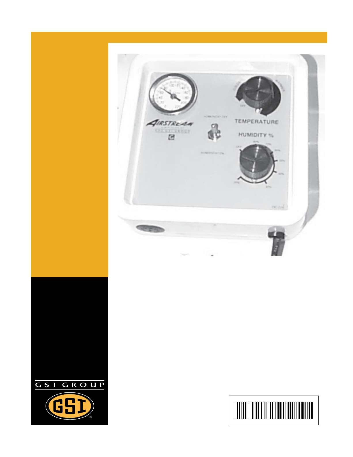
Humidistat-Thermostat
Model # HF _-_ _-_ _-
Owner ’s Manual
PNEG-236
Date: 12-02-09
PNEG-236
Page 2

2 PNEG-236 Humidistat-Thermostat
Page 3

Table of Contents
Contents
Chapter 1 Safety .................................................................................................................................................. 4
Safety Guidelines ... ... ... ... ................................................................................................................... 4
Humidistat-Thermostat Operation ...................................................................................................... 5
Chapter 2 Safety Alert Decals ......................................... ... ... ............................................. ................................ 6
Chapter 3 General Installation ........................................................................................................................... 9
Installation Instructions ................. .... ... ... ... ... .......................................... .... ... ... ... .... ... ... .......... ... ........ 9
Chapter 4 Installation of Top Dry High-Low Thermostat .............................................................................. 10
Installation Instructions ................. .... ... ... ... ... .......................................... .... ... ... ... .... ... ... ................... 10
Chapter 5 Operation ......................................................................................................................................... 11
Temperature Control ........................................................................................................................ 11
Humidity Control ............................................................................................................................... 11
Chapter 6 Operation and Service .................................................................................................................... 12
High-Low Temperature Control ........................................................................................................ 12
Humidistat-Thermostat Service ........................................................................................................ 12
Chapter 7 Parts List .......................................................................................................................................... 13
Humidistat-Thermostat Parts ........................................................................................................... 13
Low-Temperature Humidistat-Thermostat Parts ........................................................... ... ... .... ... ... ... 14
High-Low Humidistat-Thermostat Parts ................................. .... ... ... ... ... .... ... ... ... .... ... ... ................... 15
Chapter 8 Wiring Diagrams .............................................................................................................................. 16
Humidistat-Thermostat Wiring .......................................................................................................... 16
Thermostat Wiring .................................. ... ... .... ... ... ... .... ... .......................................... ... ... ................ 17
Humidistat Wiring ............................................................................................................................. 18
High-Low Thermostat Wiring ..................... ... .... ... ... ... .... ... ... ... .......................................... ... .... ......... 19
Chapter 9 Mounting Template ......................................................................................................................... 20
Chapter 10 Warranty ......................................................................................................................................... 21
PNEG-236 Humidistat-Thermostat 3
Page 4
1. Safety
Safety Guidelines
This manual contains information that is important for you, the owner/operator, to know and understand.
This information relates to protecting personal safety and preventing equipment problems. It is the
responsibility of the owner/operator to inform anyone operating or working in the area of this equipment
of these safety guidelines. To help you recognize this information, we use the symbols that are defined
below. Please read the manual and pay attention to these sections. Failure to read this manual and its
safety instructions is a misuse of the equipment and may lead to serious injury or death.
This is the safety alert symbol. It is used to alert you
to potential personal injury hazards. Obey all safety
messages that follow this symbol to avoid possible
injury or death.
DANGER indicates an imminently hazardous situation
which, if not avoided, will result in death or serious injury.
WARNING indicates a potentially hazardous situation
which, if not avoided, could result in death or serious injury.
CAUTION indicates a potentially hazardous situation which,
if not avoided, may result in minor or moderate injury.
CAUTION used without the safety alert symbol indicates a
potentially hazardous situation which, if not avoided, may
result in property damage.
NOTE indicates information about the equipment that you
should pay special attention.
WARNING! BE ALERT!
Personnel operating or working around electric fans should read this manual. This
manual must be delivered with the equipment to its owner. Failure to read this manual
and its safety instructions is a misuse of the equipment.
4 PNEG-236 Humidistat-Thermostat
Page 5

1. Safety
Humidistat-Thermostat Operation
Thank you for choosing a GSI product. It is designed to give excellent performance and service for
many years.
Our foremost concern is your safety and the safety of others associated with this equipment. We want
to keep you as a customer. This manual is to help you understand safe operating p rocedures and some
problems which may be encountered by the operator and other personnel.
As owner and/or operator, it is your responsibility to know what requirements, hazards and precautions
exist, and to inform all personnel associated with the equipment or in the area. Safety precautions may
be required from the personnel. Avoid any alterations to the equipment. Such alterations may produce
a very dangerous situation where SERIOUS INJURY or DEATH may occur.
PNEG-236 Humidistat-Thermostat 5
Page 6
2. Safety Alert Decals
The GSI Group recommends contacting your local power company, and having a representative survey
the installation so the wiring is compatible with their system, and adequate power is supplied to the unit.
Safety decals should be read and understood by all people in the grain handling area. If a decal is
damaged or missing, contact:
GSI Decals
1004 E. Illinois St.
Assumption, IL. 62510
Phone: 1-217-226-4421
A free replacement will be sent to you.
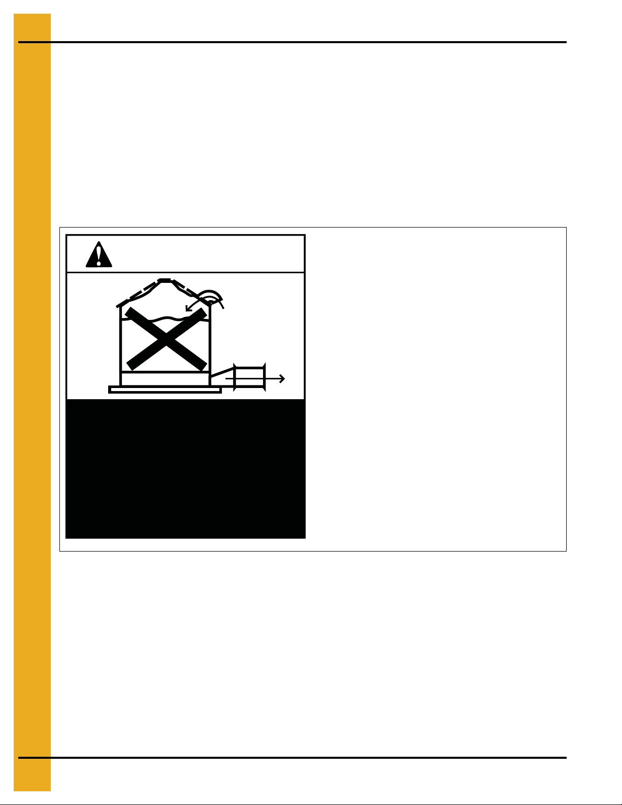
Roof Damage Warning and Disclaimer
GSI does not warrant any roof damage caused by
CAUTION!
excessive vacuum or internal pressure from fans
or other air moving systems. Adequate ventilation
and/or “Makeup Air” devices should be provided
for all powered air handling systems. GSI does not
recommend the use of downward flow systems
(suction). Severe roof damage can result from any
blockage of air passages. Running fans during
high humidity/cold weather conditions can cause
air exhaust or intake ports to freeze.
Excessive vacuum (or pressure) may
damage roof. Use positive aeration
system. Make sure all roof vents are
open and unobstructed. Start roof
fans when supply fans are started.
Do not operate when conditions exist
that may cause roof vent icing.
DC-969
6 PNEG-236 Humidistat-Thermostat
Page 7
2. Safety Alert Decals
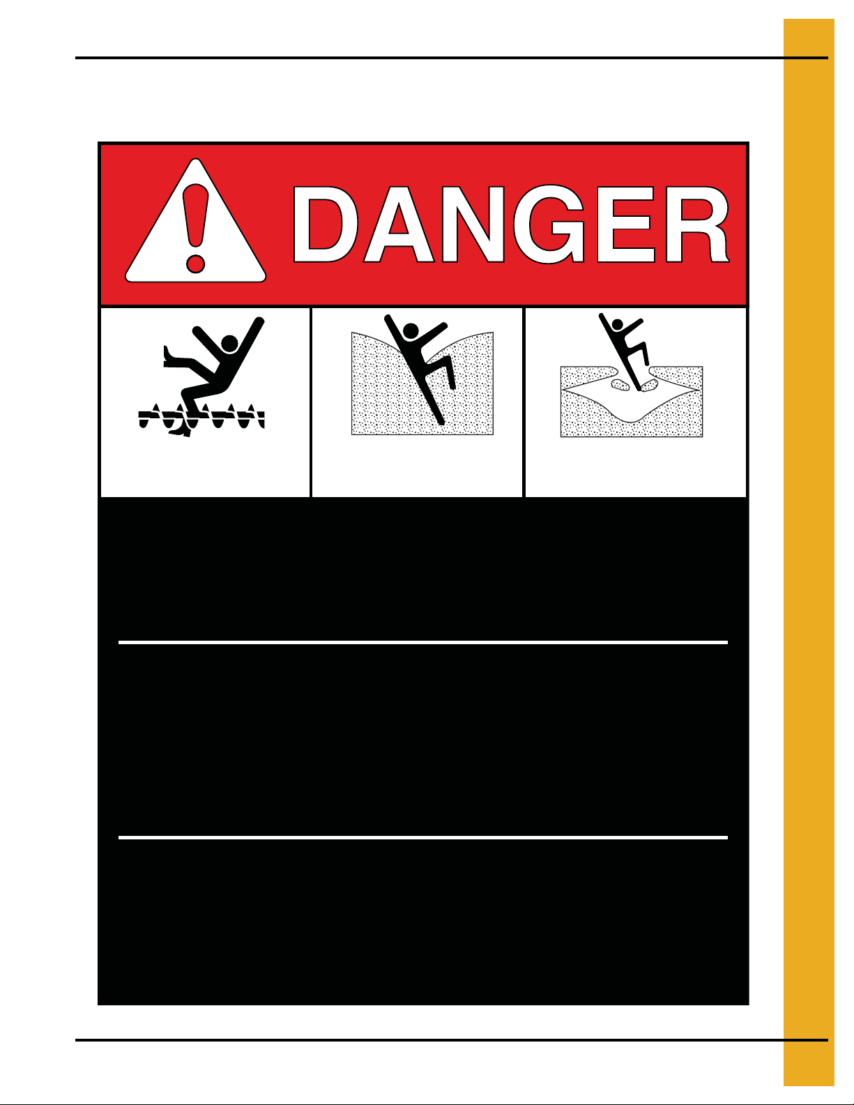
ATTENTION: The decal shown below should be present on the outside of the door cover of the 2 ring,
24" porthole door cover and the roof manway cover.
Rotating flighting will
kill or dismember.
Flowing material will
trap and suffocate.
Crusted material will
collapse and suffocate.
Keep clear of all augers.
DO NOT ENTER this bin!
If you must enter the bin:
1. Shut off and lock out all power.
2. Use a safety harness and safety line.
3. Station another person outside the bin.
4. Avoid the center of the bin.
5. Wear proper breathing equipment or respirator.
Failure to heed these
warnings will result in
serious injury or death.
DC-GBC-1A
PNEG-236 Humidistat-Thermostat 7
Page 8

2. Safety Alert Decals
HIGH VOLTAGE.
Will cause serious
injury or death.
Lockout power
before servicing.
DC-1224
WARNING
Flame and pressure beyond
door can cause serious
injury. Do not operate with
service door removed. Keep
head and hands clear.
WARNING
DC-1227
Stay clear of rotating
blade. Blade could start
automatically. Can cause
serious injury. Disconnect
power before servicing.
DC-1225
8 PNEG-236 Humidistat-Thermostat
Page 9

3. General Installation
Figure 3A 24" is the approximate distance from the edge of the transition to the edge
of the humidistat installation.
Installation Instructions
Standard electrical safety practices and codes should be used when installing the HumidistatThermostat. Refer to the National Electric Code Standard Handbook by the National Fire Protection
Association. A qualified electrician should make all wiring installations.
Always disconnect and lock out power before working on or around heater.
1. The Humidistat-Thermostat should be mounted on the side of the bin wall between the foundation
and the drying floor. It should be installed approximately 24" from the right side of the transition as
shown in
2. Use the template on Page 20. With these instructions, drill only the holes necessary for the
particular model. (NOTE: For humidistat to operate properly optional cutout must be used.)
3. Caulk the top and sides of the plastic housing using roll caulking supplied with the unit. Do not caulk
the bottom side of housing so moisture can escape.
4. Carefully insert sensing probes through bin wall and secure housing to wall using self-drilling
screws provided. Be careful not to overtighten screws. Damage to housing could result.
Figure 3A
.
5. Make wiring connections to heater as shown in heater Owner’s manual.
PNEG-236 Humidistat-Thermostat 9
Page 10

4. Installation of Top Dry High-Low Thermostat
The High-Low thermostat is designed for use with the GSI top dry crop dryer units. It comes with one
thermostat which is adjustable and cycles the heater from high to low flame. The High-Low thermostat
also comes with a thermometer for monitoring the plenum temperature.
Installation Instructions
1. Locate the mounting position of the thermostat as shown in Figure 4A.
2. Use the template on Page 20. With these instructions, drill only the holes necessary for the
particular model.
3. Apply rope caulk to sides and top of plastic housing. Leave bottom open to let moisture escape.
4. Secure housing to sidewall using self-drilling screws supplied. Be careful not to overtighten.
Overtightening may cause the housing to crack.
rd
5. Connect the black and white wires to the terminals marked bin High-Limit (3
bottom left hand terminal strip) on fan and heater safety circuit board.
th
6. Connect the green and red wires to the terminals marked cycle (8
and 6th terminal bottom left hand
terminal strip) on fan and heater safety circuit board.
and 4th terminal
Figure 4A Placement of the Top Dry High-Low Thermostat
10 PNEG-236 Humidistat-Thermostat
Page 11

5. Operation
Temperature Control
1. Turn the fan unit ON and let it run 3 to 5 minutes to equalize temperature under the bin.
2. Set bypass switch to the “HUMIDISTAT OFF” position. This setting allows the unit to run based on
temperature only.
3. Rotate the thermostat knob clockwise to the warmest position.
4. Open the gas valves to the heater and turn the heater ON. Set heater gas pressure to a moderately
high setting (5 to 10 PSI).
5. Monitor the thermometer on the thermostat housing. When the thermometer comes up to the desired
temperature, slowly turn the thermostat knob counterclockwise until the heater cycles OFF.
6. If the unit does not reach the desired temperature, gradually increase the gas pressure until the
temperature rises to the desired level.
7. Watch the unit run through several cycles and make any final adjustments. (NOTE: The unit should
be on approximately 80% of the time. If not adjust gas pressure.)
8. Significant changes in outside air temperature may require readjustment of gas pressure.
Humidity Control
1. Set bypass switch to the “HUMIDISTAT ON” position. This setting allows the unit to run based on
temperature and humidity.
2. Set the thermostat (Humidistat-Thermostat units only) to the maximum temperature desired. This
allows the thermostat to function as a High-Limit control only. See the above Temperature Control
for setting the thermostat.
3. Set the humidistat to the desired relative humidity level you want to maintain under the drying floor.
The heater will cycle on above this relative humidity, and OFF when this level is reached.
4. Use the equilibrium moisture chart below as a guide for setting the humidistat.
Equilibrium Moisture Chart (Shelled Corn)
Air
T emperature
(F)
20° 11.2 11.7 12.7 13.7 14.5 15.1 16.2 17.1 18.0 19.6 21.2 23.5 25.8 29.1
30° 10.8 11.3 12.2 13.1 13.9 14.6 15.5 16.4 17.4 18.7 20.2 22.5 25.0 28.3
40° 10.5 11.0 11.7 12.5 13.3 14.0 14.8 15.5 16.6 17.8 19.4 21.5 24.2 27.5
50° 10.1 10.6 11.3 12.0 12.7 13.3 14.1 14.8 15.8 16.9 18.6 20.5 23.4 26.7
35 40 45 50 55 60 65 70 75 80 85 90 95 100
Relative Humidity - Percentage (%)
60° 9.7 10.2 10.9 11.6 12.1 12.7 13.4 14.2 15.0 16.0 17.8 19.5 22.6 25.9
70° 9.0 9.7 10.4 11.1 11.5 12.0 12.8 13.5 14.5 15.4 16.8 18.5 21.3 24.5
80° 8.3 9.1 9.8 10.5 10.8 11.2 12.1 13.0 13.9 14.8 15.8 17.4 20.0 22.8
Boxed area indicates safe moisture for normal winter storage of shelled corn at 15%. Grain
to be stored through the summer or long term, needs to be 1 to 3 points dryer.
PNEG-236 Humidistat-Thermostat 11
Page 12

6. Operation and Service
High-Low Temperature Control
1. Turn fan unit ON and let it run 3 to 5 minutes to equalize temperature under the bin.
2. Rotate the thermostat knob clockwise to warmest position.
3. Open gas valves (including Low-Fire valve) to the heater and turn the heater ON. Set heater gas
pressure to a moderately high setting (5 to 10 PSI).
4. Monitor the thermometer on the thermostat housing. When the thermostat comes up to desired
temperature, slowly turn the most at knob counterclockwise until heater cycles to Low-Flame.
5. If the unit does not reach desired temperature, gradually increase the gas pressure until the
temperature rises to desired level.
6. Adjust the Low-Fire valve so that the temperature drops until the unit cycles back to High-Flame.
7. Watch the unit run through several cycles and make any final adjustments. (NOTE: The unit should
cycle approximately two (2) times per minute. If not adjust gas pressure.)
8. Significant changes in outside air temperature may require readjustment of gas pressure.
NOTE: If temperature of Low-Flame exceeds thermostat settings (above normal outside temperat ures)
unit will cycle from Low-Flame to OFF. (Top dry units will shut down completely.)
Humidistat-Thermostat Service
GSI thermostats are designed and built to withstand the harsh conditions usually found in drying bins. A
yearly preventative maintenance inspection may extend the life of the heating controls many years.
Always disconnect and lock out power before working on or around heater.
1. Remove mounting screws from the thermostat housing and remove the housing from the bin wall.
2. Carefully remove the back panel from the housing. (It may be necessary to cut caulking.)
3. Blow out any dust or dirt that may have collected inside the housing.
4. Inspect the wiring for any loose connections, or rodent and insect damage.
5. Replace the back panel and caulk the corners to help seal the unit.
6. Reinstall the unit on the bin wall.
The Airstream Humidistat-Thermostat is mounted
on the lower right side of the grain bin’s transition.
This allows for easy service and operation.
Figure 6A
12 PNEG-236 Humidistat-Thermostat
Page 13

Humidistat-Thermostat Parts
7. Parts List
Ref # Part # Description
1 HF-1431 2.66" Plastic Housing
1 HF-1446 4.00" Plastic Housing
2 HF-1432 Thermostat
3 HF-1433 Humidistat
4 HF-1434 Static Pressure Gauge
5 HH-1435 220° Thermometer
6 HH-1436 Screen Plug
7 HH-1970 Plastic Knob
8 HH-2089 Large Red Plastic Plug
9 HH-1442 Toggle Switch
10 HF-7108 Thermostat Cover
11 HH-7032 Rubber Grommet
12 HH-7029 Heat Shrink Tube 1/2"
13 HF-7110 Humidistat Cover
PNEG-236 Humidistat-Thermostat 13
Page 14

7. Parts List
Low-Temperature Humidistat-Thermostat Parts
Ref # Part # Description
1 HF-1431 2.66" Plastic Housing
1 HF-1446 4.00" Plastic Housing
2 HF-3974 Low-Temperature Thermostat
3 HF-1433 Humidistat
4 HF-1434 Static Pressure Gauge
5 HH-3973 140° Thermometer
6 HH-1436 Screen Plug
7 HH-1970 Plastic Knob
8 HH-2089 Large Red Plastic Plug
9 HH-1442 Toggle Switch
10 HF-7108 Thermostat Cover
11 HH-7032 Rubber Grommet
12 HF-7110 Humidistat Cover
14 PNEG-236 Humidistat-Thermostat
Page 15

High-Low Humidistat-Thermostat Parts
7. Parts List
Ref # Part # Description
1 HF-1431 2.66" Plastic Housing
1 HF-1446 4.00" Plastic Housing
2 HF-7028 Low-Temperature Thermostat
3 HF-1434 Static Pressure Gauge
4 HF-1435 220° Thermometer
5 HH-1436 Screen Plug
6 HH-1970 Plastic Knob
7 HH-2089 Large Red Plastic Plug
8 HH-7029 Heat Shrink Tube 1/2"
9 HH-7108 Thermostat Cover
10 HF-7032 Rubber Grommet
11 HF-7110 Humidistat Cover
PNEG-236 Humidistat-Thermostat 15
Page 16

8. Wiring Diagrams
Humidistat-Thermostat Wiring
16 PNEG-236 Humidistat-Thermostat
Page 17

Thermostat Wiring
8. Wiring Diagrams
PNEG-236 Humidistat-Thermostat 17
Page 18

8. Wiring Diagrams
Humidistat Wiring
18 PNEG-236 Humidistat-Thermostat
Page 19

High-Low Thermostat Wiring
8. Wiring Diagrams
PNEG-236 Humidistat-Thermostat 19
Page 20

9. Mounting Template
20 PNEG-236 Humidistat-Thermostat
Page 21

10. Warranty
GSI Group, LLC Limited Warranty
The GSI Group, LLC (“GSI”) warrants products which it manufactures to be free of defects in materials and workmanship
under normal usage and conditions for a period of 12 months after sale to the original end-user or if a foreign sale,
14 months from arrival at port of discharge, whichever is earlier. The end-user’s sole remedy (and GSI’s only obligation)
is to repair or replace, at GSI’s option and expense, products that in GSI’s judgment, contain a material defect in materials
or workmanship. Expenses incurred by or on behalf of the end-user without prior written authorization from the GSI
Warranty Group shall be the sole responsibility of the end-user.
Warranty Extensions:
The Limited Warranty period is extended for the following products:
Product Warranty Period
Performer Series Direct Drive Fan Motor 3 Years
AP Fans and Flooring
Cumberland
Feeding/Watering
Systems
Grain Systems Grain Bin Structural Design 5 Years
Grain Systems
Farm Fans
Zimmerman
All Fiberglass Housings Lifetime
All Fiberglass Propellers Lifetime
Feeder System Pan Assemblies 5 Years **
Feed Tubes (1-3/4" and 2.00") 10 Years *
Centerless Augers 10 Years *
Watering Nipples 10 Years *
Portable and Tower Dryers 2 Years
Portable and Tower Dryer Frames and
Internal Infrastructure †
5 Years
* Warranty prorated from list price:
0 to 3 years - no cost to end-user
3 to 5 years - end-user pays 25%
5 to 7 years - end-user pays 50%
7 to 10 years - end-user pays 75%
** Warranty prorated from list price:
0 to 3 years - no cost to end-user
3 to 5 years - end-user pays 50%
† Motors, burner components
and moving parts not included.
Portable dryer screens included.
Tower dryer screens not included.
GSI further warrants that the portable and tower dryer frame and basket, excluding all auger and auger drive
components, shall be free from defects in materials for a period of time beginning on the twelfth (12
the date of purchase and continuing until the sixtieth (60
th
) month from the date of purchase (extended warranty period).
th
) month from
During the extended warranty period, GSI will replace the frame or basket components that prove to be defective
under normal conditions of use without charge, excluding the labor, transportation, and/or shipping costs incurred in
the performance of this extended warranty.
Conditions and Limitations:
THERE ARE NO WARRANTIES THAT EXTEND BEYOND THE LIMITED WARRANTY DESCRIPTION SET FORTH
ABOVE. SPECIFICALLY, GSI MAKES NO FURTHER WARRANTY OF ANY KIND, EXPRESS OR IMPLIED,
INCLUDING, WITHOUT LIMITATION, WARRANTIES OF MERCHANTABILITY OR FITNESS FOR A PARTICULAR
PURPOSE OR USE IN CONNECTION WITH: (I) PRODUCT MANUFACTURED OR SOLD BY GSI OR (II) ANY
ADVICE, INSTRUCTION, RECOMMENDATION OR SUGGESTION PROVIDED BY AN AGENT, REPRESENTATIVE
OR EMPLOYEE OF GSI REGARDING OR RELATED TO THE CONFIGURATION, INSTALLATION, LAYOUT,
SUITABILITY FOR A PARTICULAR PURPOSE, OR DESIGN OF SUCH PRODUCTS.
GSI shall not be liable for any direct, indirect, incidental or consequential damages, including, without limitation, loss of
anticipated profits or benefits. The sole and exclusive remedy is set forth in the Limited Warranty, which shall not exceed
the amount paid for the product purchased. This warranty is not transferable and applies only to the original end-user.
GSI shall have no obligation or responsibility for any representations or warranties made by or on behalf of any dealer,
agent or distributor.
GSI assumes no responsibility for claims resulting from construction defects or unauthorized modifications to products
which it manufactured. Modifications to products not specifically delineated in the manual accompanying the equipment
at initial sale will void the Limited Warranty.
This Limited Warranty shall not extend to products or parts which have been damaged by negligent use, misuse,
alteration, accident or which have been improperly/inadequately maintained. This Limited Warranty extends solely to
products manufactured by GSI.
Prior to installation, the end-user has the responsibility to comply with federal, state and local codes which apply to the
location and installation of products manufactured or sold by GSI.
9101239_1_CR_rev7.DOC (revised July 2009)
PNEG-236 Humidistat-Thermostat 21
Page 22

This equipment shall be installed in accordance with
the current installation codes and applicable
regulations which should be carefully followed in all
cases. Authorities having jurisdiction should be
consulted before installations are made.
Copyright © 2009 by GSI Group
Printed in the USA
GSI Group
1004 E. Illinois St.
Assumption, IL 62510-0020
Phone: 1-217-226-4421
Fax: 1-217-226-4420
www.gsiag.com
 Loading...