

Page 1
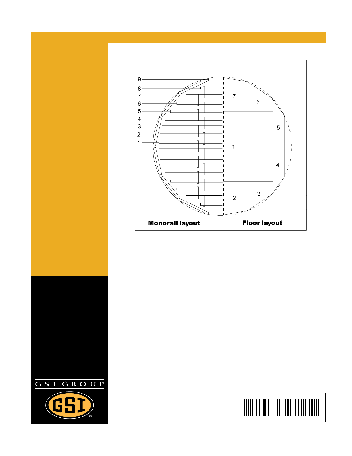
GSI Corrugated Floor and
Monorail Layouts
Owner ’s Manual
PNEG-225
Date: 11-13-08
PNEG-225
Page 2

2 PNEG-225 Corrugated Floor and Monorail Layouts
Page 3

Table of Contents
Contents
Chapter 1 Introduction ........................................................................................................................................ 4
Chapter 2 Safety ..................................................................................................................................................5
Safety Guidelines ............................................................................................................................... 5
General Safety Statement ................................................................ ... ... .... ... ... ... ............................... 6
Safety Instructions .............................................................................................................................. 7
Safety Sign-Off Sheet ......................................................................................................................... 9
Proper Storage Grain Bin/Silo Materials Prior to Construction ......................................................... 10
Chapter 3 Safety Decals ...................................................................................................................................11
Chapter 4 Monorail Installation ....................... ......................... .......................... ..............................................14
Tie Bar Detail .................................................................................................................................... 14
Assembling Legs to Rail ................................................................................................................... 14
Splicing Rails .................................................................................................................................... 15
Suggested Screw Locations ............................................................................................................. 17
Outer Perimeter Rail Detail .............................................................................................................. 18
Flashing Installation ....................................................... ... ... ... .... ................................................ ... ... 19
Grain Systems Formed Flashing Installation .................................................................................... 19
Chapter 5 Layouts .............................................................................................................................................20
12' Bin Floor Layouts ........................................................................................................................ 20
15' Bin Floor Layouts ........................................................................................................................ 22
18' Bin Floor Layouts ........................................................................................................................ 24
20' Bin Floor Layouts ........................................................................................................................ 26
21' Bin Floor Layouts ........................................................................................................................ 28
24' Bin Floor Layouts ........................................................................................................................ 30
25' Bin Floor Layouts ........................................................................................................................ 32
27' Bin Floor Layouts ........................................................................................................................ 34
30' Bin Floor Layouts ........................................................................................................................ 36
33' Bin Floor Layouts ........................................................................................................................ 38
36' Bin Floor Layouts ........................................................................................................................ 40
39' Bin Floor Layouts ........................................................................................................................ 43
40' Bin Floor Layouts ........................................................................................................................ 46
42' Bin Floor Layouts ........................................................................................................................ 49
45' Bin Floor Layouts ........................................................................................................................ 52
48' Bin Floor Layouts ........................................................................................................................ 55
54' Bin Floor Layouts ........................................................................................................................ 58
60' Bin Floor Layouts ........................................................................................................................ 61
72' Bin Floor Layouts ........................................................................................................................ 64
75' Bin Floor Layouts ........................................................................................................................ 67
78' Bin Floor Layouts ........................................................................................................................ 70
90' Bin Floor Layouts ........................................................................................................................ 73
105' Bin Floor Layouts .. .......................................... ... .... ... ... .......................................... ... .......... ...... 76
Chapter 6 Warranty ...........................................................................................................................................79
PNEG-225 Corrugated Floor and Monorail Layouts 3
Page 4

1. Introduction
READ THIS MANUAL carefully to learn how to properly use and install equipment. Failure to do so could
result in personal injury or equipment damage.
INSPECT the shipment immediately upon arrival. The customer is responsible for ensuring that all
quantities are correct. The customer should report and note any damage or shortage on the bill of
lading to justify their claim to the transport company.
THIS MANUAL SHOULD BE CONSIDERED a permanent part of your equipment and should be easily
accessible when needed.
This warranty provides you the assurance that the company will back its products when defects appear
within the warranty period. In some circumstances, the company also provide s field improvements, often
without charge to the customer, even if the product is out of warranty. Should the equipment be abused,
or modified to change its performance beyond the factory specifications, the warranty will be come void
and field improvements may be denied.
4 PNEG-225 Corrugated Floor and Monora il Layouts
Page 5
2. Safety
Safety Guidelines
This manual contains information that is important for you, the owner/operator, to know and understand.
This information relates to protecting personal safety and preventing equipment problems. It is the
responsibility of the owner/operator to inform anyone operating or working in the area of this equipment
of these safety guidelines. To help you recognize this information, we use the symbols that are defined
below. Please read the manual and pay attention to these sections. Failure to read this manual and its
safety instructions is a misuse of the equipment and may lead to serious injury or death.
This is the safety alert symbol. It is used to alert you to
potential personal injury hazards. Obey all safety
messages that follow this symbol to avoid possible
injury or death.
DANGER indicates an imminently hazardous situation
which, if not avoided, will result in death or serious injury.
WARNING indicates a potentially hazardous situation
which, if not avoided, could result in death or serious injury.
CAUTION indicates a potentially hazardous situation which,
if not avoided, may result in minor or moderate injury.
CAUTION used without the safety alert symbol indicates a
potentially hazardous situation which, if not avoided, may
result in property damage.
NOTE indicates information about the equipment that you
should pay special attention.
PNEG-225 Corrugated Floor and Monorail Layouts 5
Page 6
2. Safety
General Safety Statement
Our foremost concern is your safety and the safety of others associated with grain handling equipment.
This manual is to help you understand safe operating procedures and some problems which may be
encountered by the operator and other personnel.
As owner and/or operator, you are responsible to know what requirements, hazards and precautions
exist and inform all personnel associated with the equipment or in the area. Safety precautions may be
required from the personnel. Avoid any alterations to the equipment, which may produce a very
dangerous situation, where SERIOUS INJURY or DEATH may occur.
You should consider the location of the bin site relative to power line locations or electrical transmission
equipment. Contact your local power company to review your installation plan or for information
concerning required equipment clearance. Clearance of portable equip ment that may be taken to the bin
site should also be reviewed and considered. Any electrical control equipment in contact with the bin
should be properly grounded and installed in accordance with National Electric Code provisions and
other local or national codes.
This product is intended for the use of grain storage only. Any other use is a misuse of the product.
This product has sharp edges, which may cause serious injury. To avoid injury, handle
sharp edges with caution and always use proper protective clothing and equipment.
Sidewall bundles or sheets must be stored in a safe manner. The safest method of storing sidewall
bundles is laying horizontally with the arch of the sheet upward, like a dome. Sidewall sheets stored on
edge must be secured so that they cannot fall over and cause injury. Use care when handling and moving
sidewall bundles.
Personnel operating or working around equipment should read this manual. This manual must be
delivered with equipment to its owner. Failure to read this manual and its safety instructions is a misuse
of the equipment.
6 PNEG-225 Corrugated Floor and Monorail Layouts
Page 7
2. Safety
Safety Instructions
Our foremost concern is your safety and the safety of others associated with this equipment. We want
to keep you as a customer. This manual is to help you understand safe operating proced ures and some
problems which may be encountered by the operator and other personnel.
As owner and/or operator, it is your responsibility to know what requirements, hazards and precautions
exist, and to inform all personnel associated with the equipment or in the area. Safety precautions may
be required from the personnel. Avoid any alterations to the equipment. Such alterations may produce
a very dangerous situation where SERIOUS INJURY or DEATH may occur.
This equipment shall be installed in accordance with the current installation codes and applicable
regulations which should be carefully followed in all cases. Authorities having jurisdiction should be
consulted before installations are made.
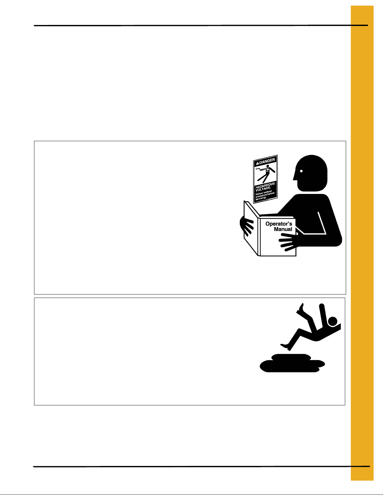
Follow Safety Instructions
Carefully read all safety messages in this manual and
safety signs on your machine. Keep signs in good
condition. Replace missing or damaged safety signs. Be
sure new equipment components and repair parts include
the current safety signs. Replacement safety signs are
available from the manufacturer.
Learn how to operate the machine and how to use controls
properly. Do not let anyone operate without instruction.
Keep your machinery in proper working condition.
Unauthorized modifications to the machine may impair
the function and/or safety and affect machine life.
If you do not understand any part of this manual or need
assistance, contact your dealer.
Practice Safe Maintenance
Understand service procedures before doing work. Keep area
clean and dry.
Never lubricate, service, or adjust machine while it is in operation.
Keep hands, feet, and clothing away from rotating parts.
Keep all parts in good condition and properly installed. Fix
damage immediately . Replace worn or broken p arts. Remove any
built up grease oil and debris.
Read and Understand Manual
Maintain Equipment
and Work Area
PNEG-225 Corrugated Floor and Monorail Layouts 7
Page 8
2. Safety
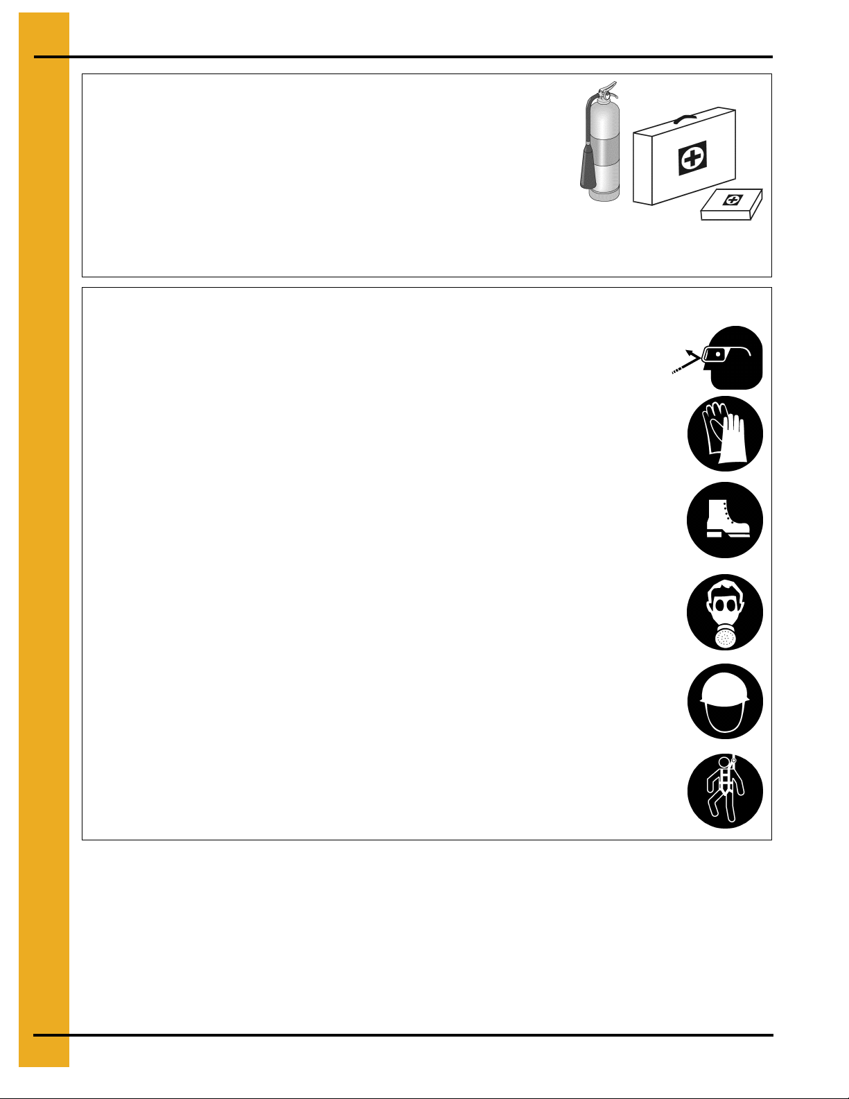
Prepare for Emergencies
Be prepared if fire starts.
Keep a first aid kit and fire extinguisher handy.
Keep emergency numbers for doctors, ambulance service,
hospital, and fire department near your telephone.
Wear Protective Clothing
Wear close fitting clothing and safety equipment appropriate
to the job.
Remove all jewelry.
Keep Emergency Equipment
Quickly Accessible
Eye Protection
Long hair should be tied up and back.
Safety glasses should be worn at all times to protect eyes
from debris.
Wear gloves to protect your hands from sharp edges on
plastic or steel parts.
Wear steel toe boots to help protect your feet from falling
debris. Tuck in any loose or dangling shoe strings.
A respirator may be needed to prevent breathing potentially
toxic fumes and dust.
Wear hard hat to help protect your head.
Wear appropriate fall protection equipment when working at
elevations greater than six feet (6').
Gloves
Steel Toe Boots
Respirator
Hard Hat
Fall Protection
8 PNEG-225 Corrugated Floor and Monorail Layouts
Page 9

2. Safety
Safety Sign-Off Sheet
As a requirement of O.S.H.A., it is necessary for the employer to train the employee in the safe operating
and safety procedures for this auger. This sign-off sheet is provided for your convenience and personal
record keeping. All unqualified persons are to stay out of the work area at all times. It is strongly
recommended that another qualified person who knows the shut down procedure be in the area in the
event of an emergency.
Date Employee Name Supervisor Name
PNEG-225 Corrugated Floor and Monorail Layouts 9
Page 10

2. Safety
Proper Storage Grain Bin/Silo Materials Prior to Construction
Wet storage stain (rust) will develop when closely packed bundles of galvanized material, such as
sidewall and roof sheets, have moisture present. Inspect roof and sidewall bundles on arrival for any
moisture. If moisture is present, it must not be allowed to remain between the sheets. Separate the
sheets or panels immediately and wipe them down. Spray with a light oil or diesel fuel.
If possible, sidewall bundles, roof sheets and other closely packed galvanized materials should be stored
in a dry, climate controlled building. If outdoor storage is unavoidable, the materials should be stored so
that they are raised above the ground and vegetation. Any tacking and spacing materia ls should not be
corrosive or wet. Be sure to protect materials from the weather, but permit air movement around the
bundles if possible.
Storing roof bundles and sidewall sheets at a slight incline can also help minimize the presence of
moisture. Storing the bundles with the center of the dome up (like an arch) is one option for minimizing
moisture during storage. Sidewall bundles can also be stored on edge but must be secured so that they
do not fall over and cause injury.
If “white rust” or “wet storage stain” occurs, contact the manufacturer immediately about ways to
minimize the adverse effect upon the galvanized coating.
10 PNEG-225 Corrugated Floor and Monorail Layouts
Page 11
3. Safety Decals
The manufacturer does not warrant any roof damage caused by excessive vacuum or internal
pressure from fans or other air moving systems. Adequate ventilation and/or “makeup air”
devices should be provided for all powered air handling systems. The manufacturer does not
recommend the use of downward flow systems (suction). Severe roof damage can result from
any blockage of air passages. Running fans during high humidity/cold weather conditions can
cause air exhaust or intake ports to freeze.
CAUTION!
Excessive vacuum (or pressure) may
damage roof. Use positive aeration
system. Make sure all roof vents are
open and unobstructed. Start roof
fans when supply fans are started.
Do not operate when conditions exist
that may cause roof vent icing.
DC-969
PNEG-225 Corrugated Floor and Monorail Layouts 11
Page 12
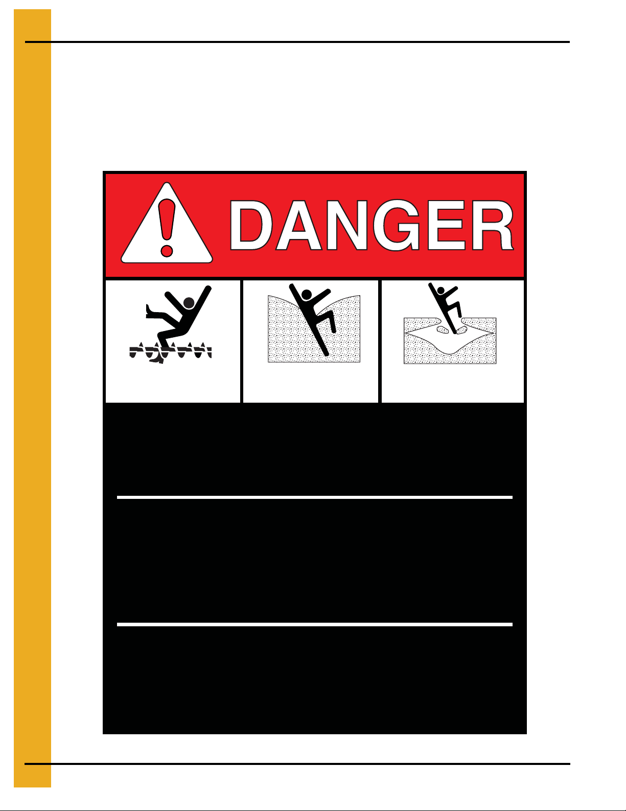
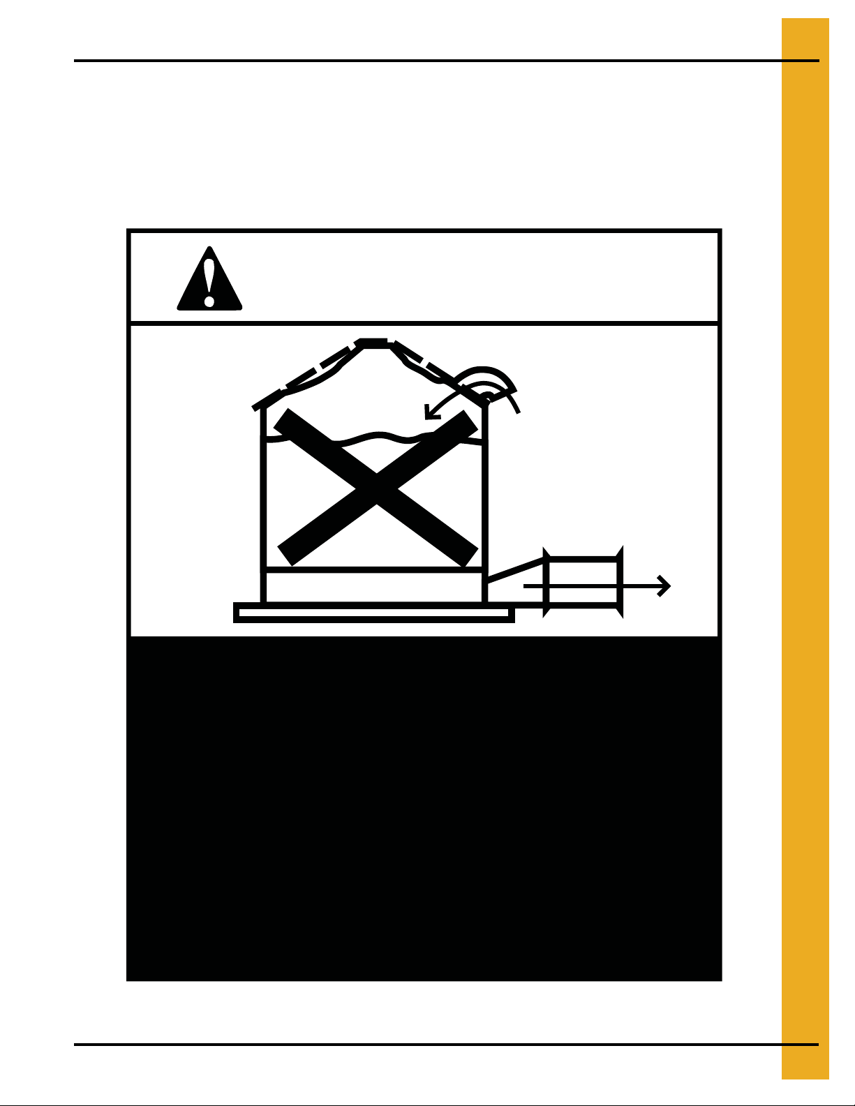
3. Safety Decals
ATTENTION: The decal shown below should be present on the outside of the door cover of the
2 ring, 24" porthole door cover and the roof manway cover. If a decal has been damaged or is missing
in any of these locations, contact the manufacturer for a free replacement decal.
GSI Decals
1004 E. Illinois St.
Assumption, IL. 62510
Phone: 217-226-4421
Rotating flighting will
kill or dismember.
Flowing material will
trap and suffocate.
Crusted material will
collapse and suffocate.
Keep clear of all augers.
DO NOT ENTER this bin!
If you must enter the bin:
1. Shut off and lock out all power.
2. Use a safety harness and safety line.
3. Station another person outside the bin.
4. Avoid the center of the bin.
5. Wear proper breathing equipment or respirator.
Failure to heed these
warnings will result in
serious injury or death.
DC-GBC-1A
12 PNEG-225 Corrugated Floor and Monorail Layouts
Page 13
3. Safety Decals
ATTENTION: The decal shown below should be present on the outside of the door cover of the
2 ring, 24" porthole door cover and the roof manway cover. If a decal has been damaged or is missing
in any of these locations, contact the manufacturer for a free replacement decal.
GSI Decals
1004 E. Illinois St.
Assumption, IL. 62510
Phone: 217-226-4421
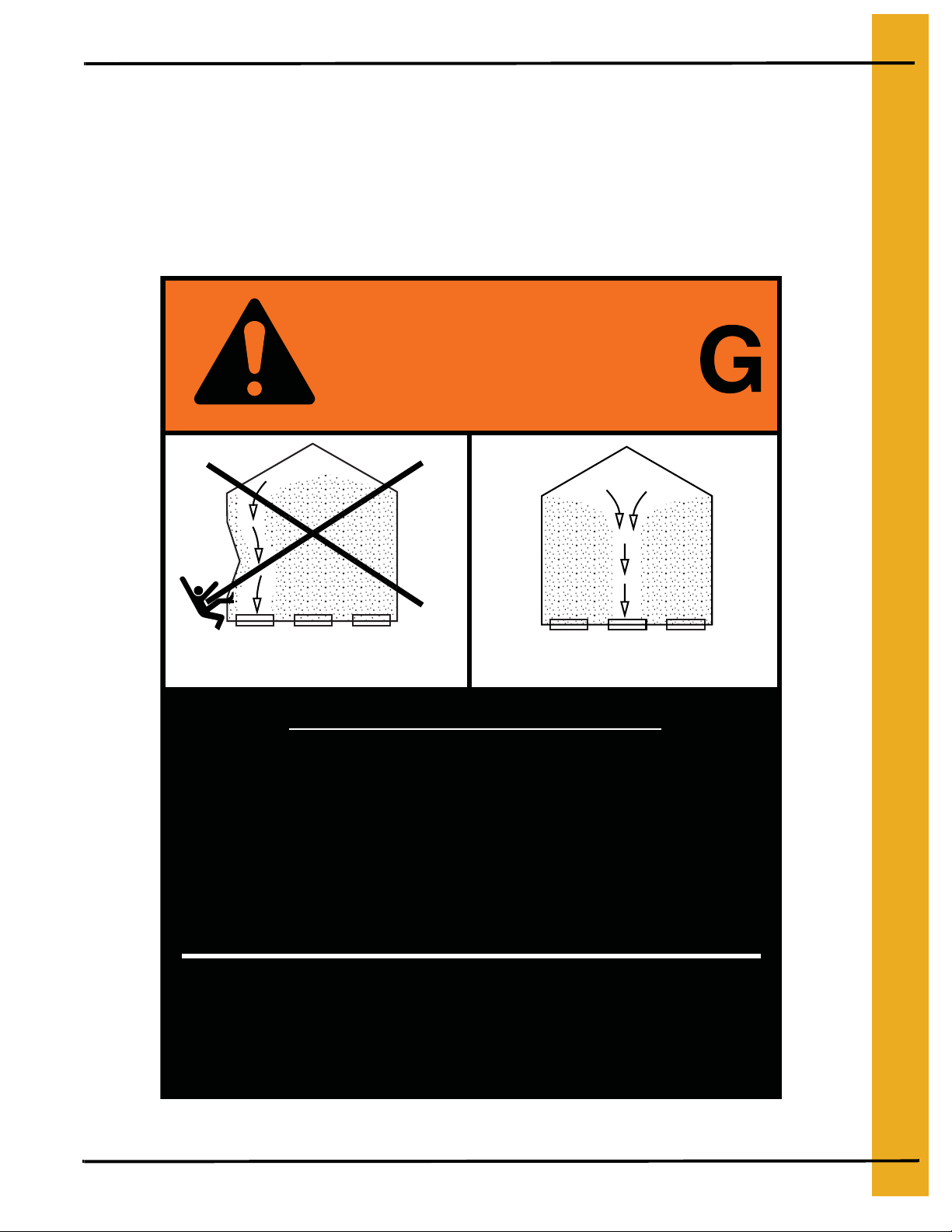
WARNIN
DON’T
DO
UNLOADING INSTRUCTIONS:
1. Use CENTER FLOOR OUTLET ONLY until NO grain
remains above this outlet.
2. Side floor outlets to be used ONLY when above
condition is satisfied.
3. Lock all side floor outlets to avoid accidental
premature use.
4. See manufacturers instructions for proper use of
factory supplied sidedraw (wall) discharge systems.
Failure to heed these warnings
could result in serious injury, death,
structural damage or collapse of tank.
DC-GBC-2A
PNEG-225 Corrugated Floor and Monorail Layouts 13
Page 14
4. Monorail Installation
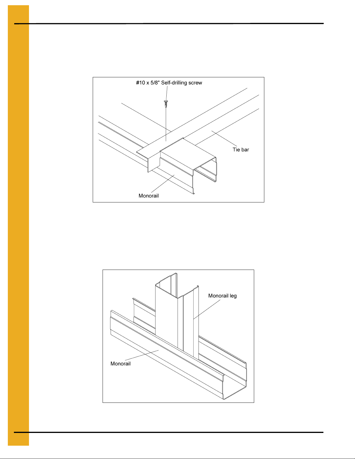
Tie Bar Detail
1. Locate the tie bars between the rails. (Spaced evenly throughout the system.)
2. A single #10 self-drilling screw may be used to fasten the tie bars at each end to the rails as
necessary. (See Figure 4A.)
Figure 4A
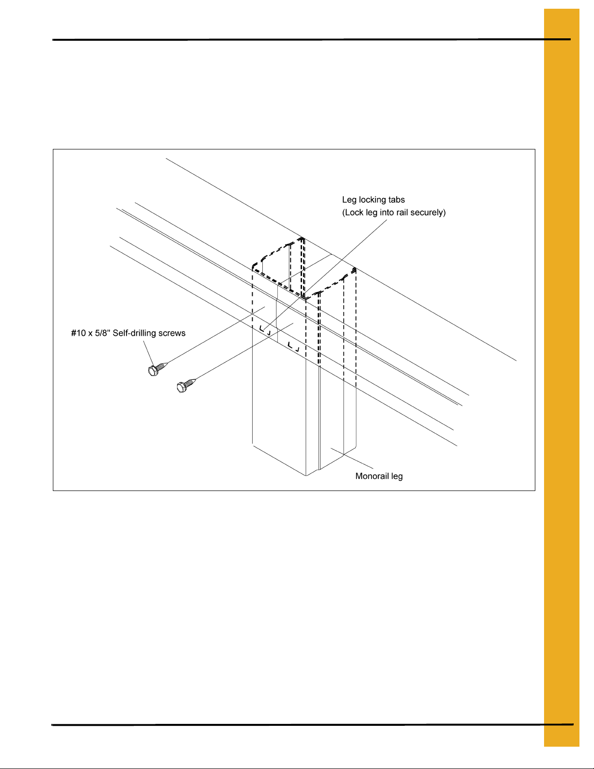
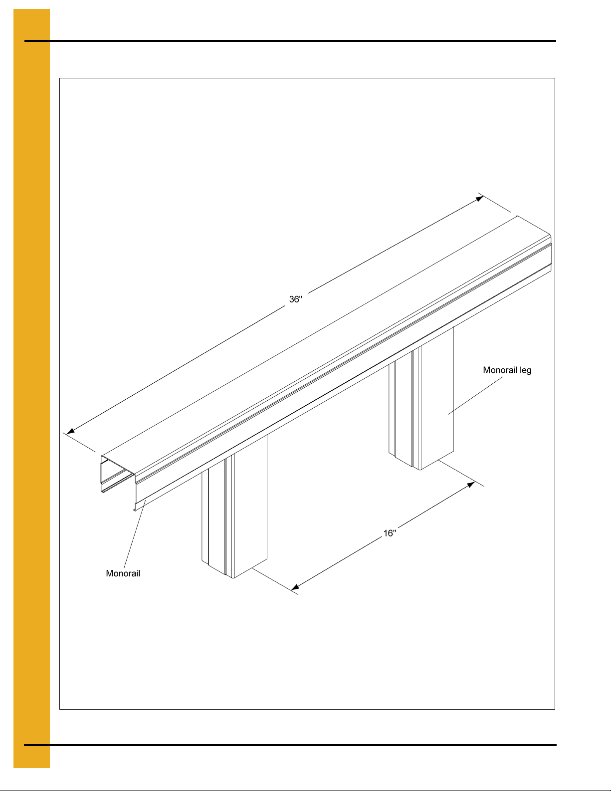
Assembling Legs to Rail
1. Place two (2) corners of the monorail leg into the rails as shown.
2. By twisting the leg it will spread the rail enough to get the other corners inside.
3. The leg can then be pushed down into the rail until the tabs lock it into place. (See Figure 4B.)
Figure 4B
14 PNEG-225 Corrugated Floor and Monorail Layouts
Page 15
4. Monorail Installation
Splicing Rails
1. A leg must be centered at each splice.
2. The closest leg may be moved a few inches over to center it under the splice. If more than 3" of
movement is required to center the leg under the splice, add an additional leg.
3. Fasten the rail to the leg with two (2) #10 self-drilling screws (splice locations only).
(See Figure 4C.)
Figure 4C
PNEG-225 Corrugated Floor and Monorail Layouts 15
Page 16
4. Monorail Installation
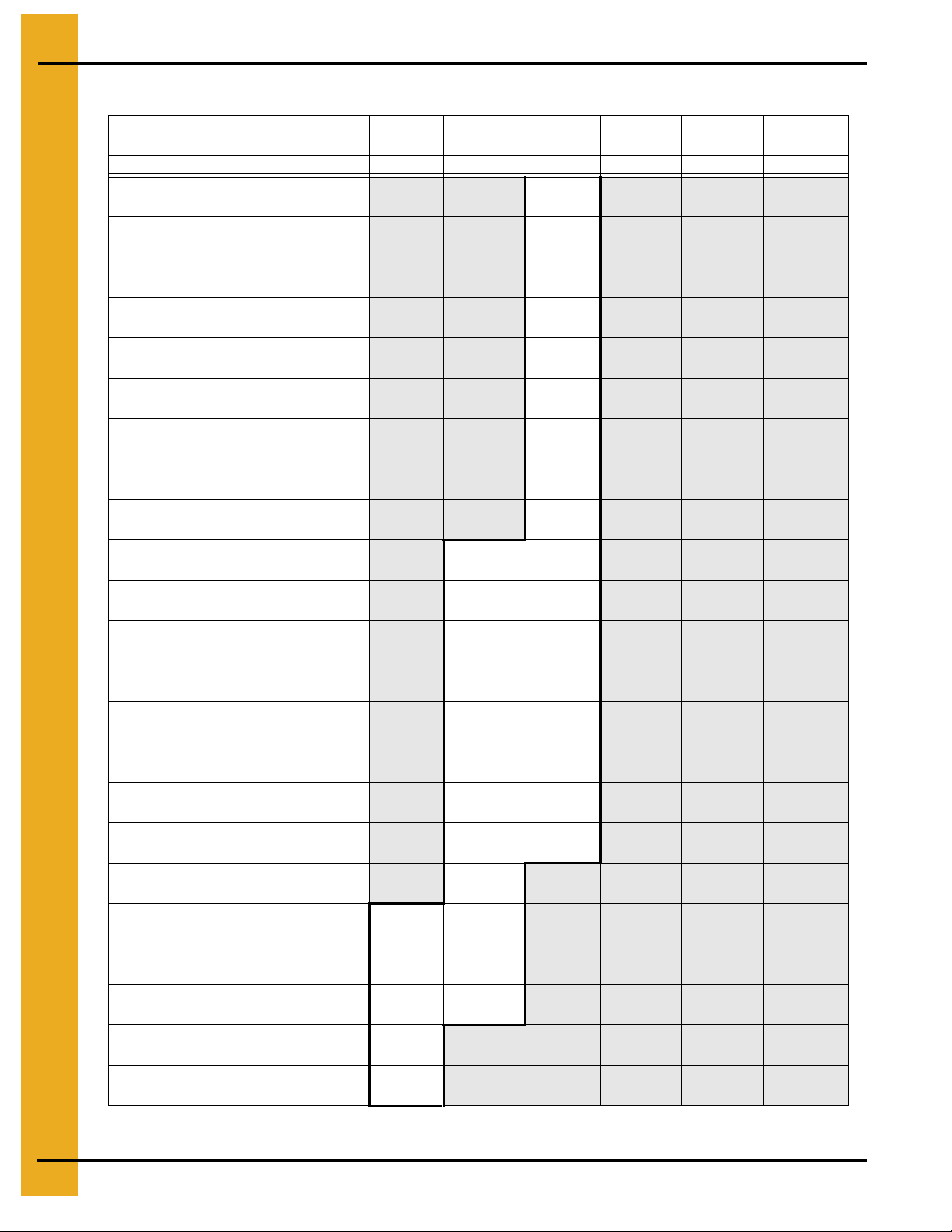
Eave Height 40' 60' 70' 80' 90' 100'
Rings of 2.66 15R 22R 26R 30R 34R
Tank Diameter Spacing # of Legs
12' 26" 22" 20" 18" 17" 16"
15' 26" 21" 20" 18" 17" 16"
18' 26" 21" 20" 18" 17" 16"
20' 26" 21" 20" 18" 17" 16"
21' 26" 21" 20" 18" 17" 16"
24' 26" 21" 20" 18" 17" 16"
25' 26" 21" 20" 18" 17" 16"
27' 26" 21" 20" 18" 17" 16"
30' 25" 21" 20" 18" 17" 16"
33' 25" 21" 20" 18" 17" 16"
36' 25" 21" 20" 18" 17" 16"
39' 24" 21" 20" 18" 17" 16"
40' 24" 21" 20" 18" 17" 16"
42' 24" 21" 20" 18" 17" 16"
45' 23" 21" 20" 18" 17" 16"
48' 23" 20" 19" 18" 17" 16"
54' 23" 20" 19" 18" 17" 16"
60' 23" 20" 19" 18" 17" 16"
72' 22" 19" 18" 17" 17" 16"
75' 22" 19" 18" 17" 17" 16"
78' 22" 19" 18" 17" 16" 16"
90' 22" 19" 18" 17" 16" 15"
105' 21" 18" 17" 16" 16" 15"
Leg Spacing Chart
82 91 97 104 108 113
113 129 133 143 149 156
178 207 214 232 242 254
208 250 260 282 295 310
288 341 355 387 406 427
310 364 378 409 428 450
355 415 431 467 488 512
387 454 473 514 538 565
562 632 654 706 736 770
690 776 803 866 904 945
716 820 855 930 974 1024
864 958 998 1086 1139 1198
796 880 915 995 1042 1094
932 1034 1076 1172 1228 1292
1169 1258 1310 1430 1500 1580
1243 1400 1454 1520 1595 1680
1670 1875 1958 2050 2152 2268
1950 2180 2276 2384 2502 2640
3086 3489 3708 3900 3900 4124
3272 3712 3890 4088 4088 4314
3544 4020 4214 4430 4674 4674
4650 5280 5538 5826 6150 6520
6962 7920 8315 8760 8760 9264
16 PNEG-225 Corrugated Floor and Monorail Layouts
Page 17
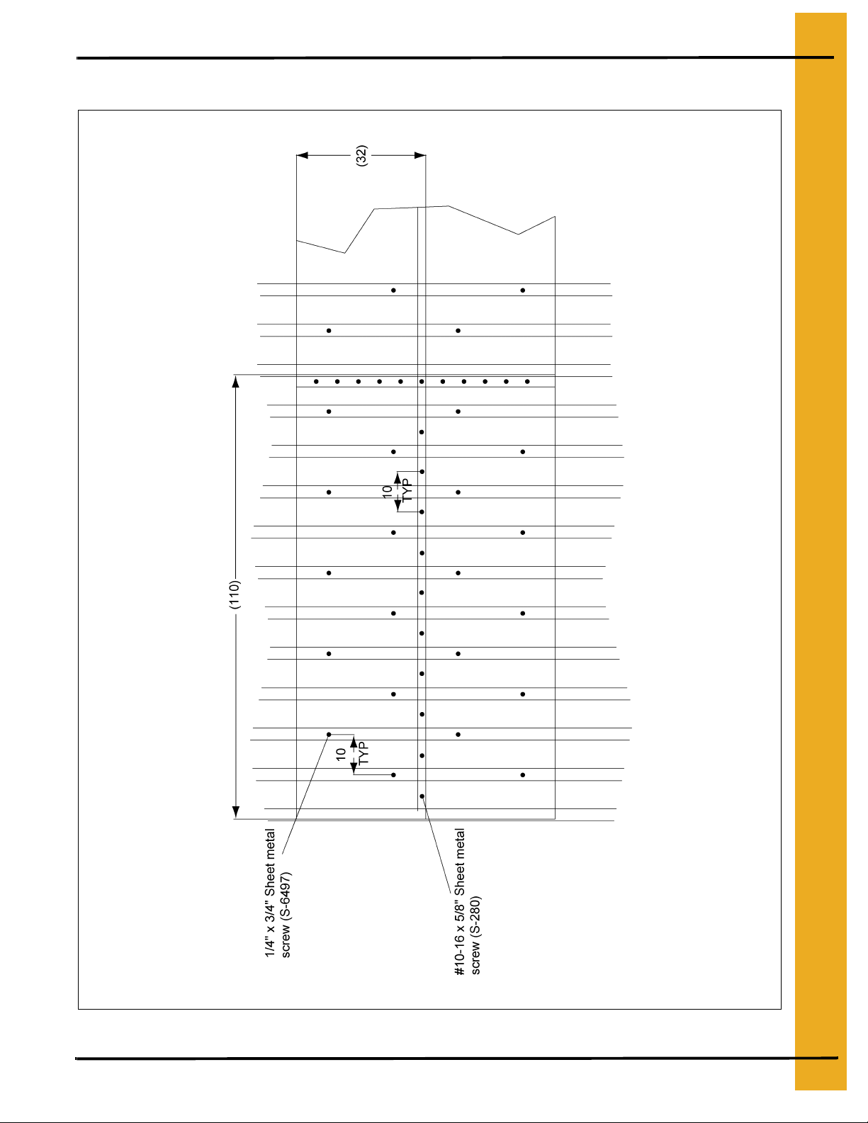
Suggested Screw Locations
4. Monorail Installation
Figure 4D
PNEG-225 Corrugated Floor and Monorail Layouts 17
Page 18
4. Monorail Installation
Outer Perimeter Rail Detail
Figure 4E
18 PNEG-225 Corrugated Floor and Monorail Layouts
Page 19
Flashing Installation
4. Monorail Installation
Figure 4F
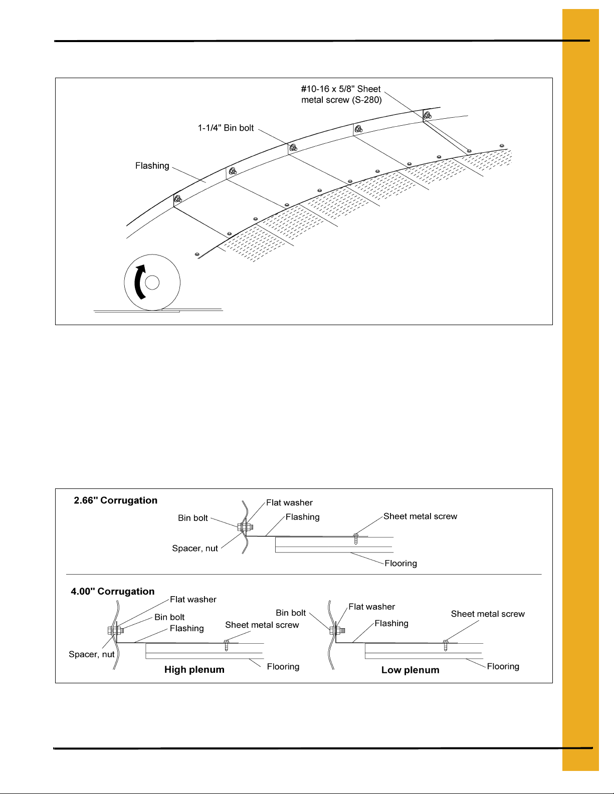
Grain Systems Formed Flashing Installation
If bin sweep auger is to be used, overlap flashing such that rotation (usually clockwise) of the sweep will
climb up on the next flashing section. This will prevent the rotating/slipping outer wheel of the sweep
from catching on the flashing edges.
After the floor is in place, lay the flashing pieces on top of the floor place over the 1-1/4" bin bolts.
See Figure 4G to determine the correct sequence for placing the nuts and washers. Finger tighten the
nuts. While holding flashing flat, fasten the flashing to the floor with sheet metal screws. Now tighten
flashing nuts.
Figure 4G
PNEG-225 Corrugated Floor and Monorail Layouts 19
Page 20
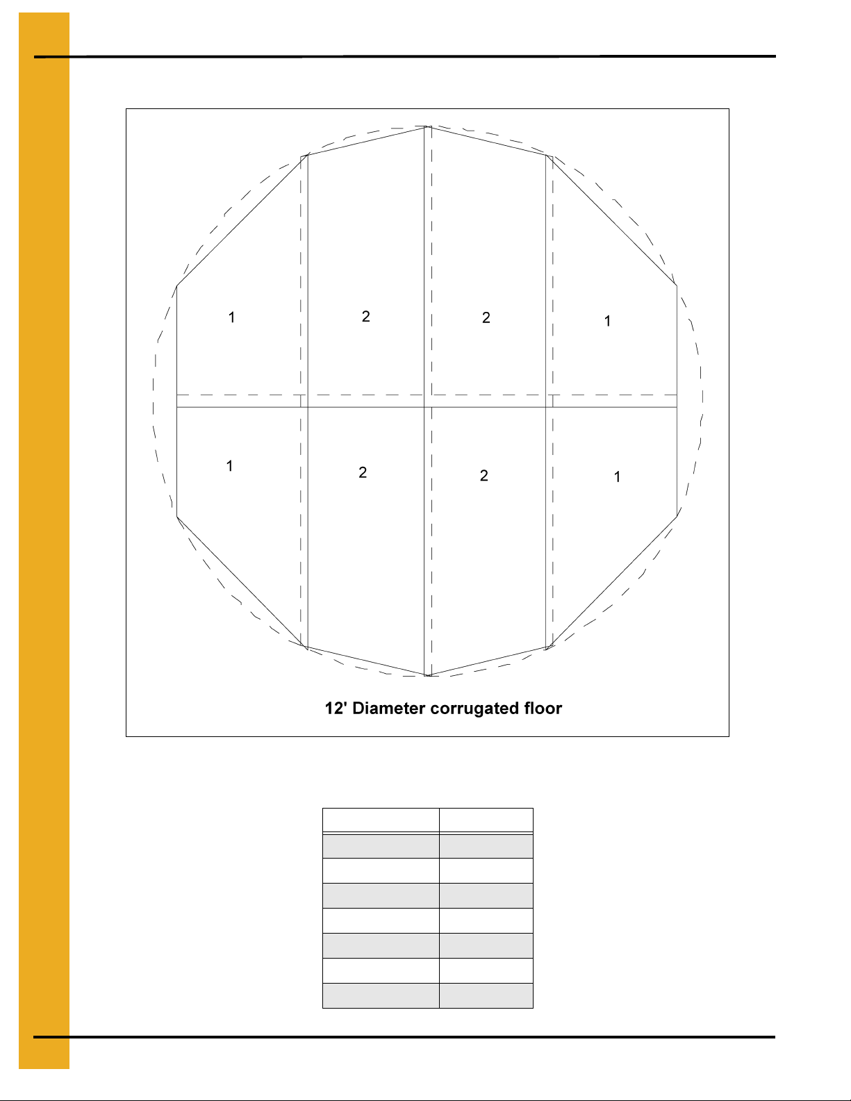
5. Layouts
12' Bin Floor Layouts
Figure 5A
12' Diameter Monorail Lengths
Monorail Number Sec 1
1 128
2 125
3 118
4 107
5 90
663
7 36
20 PNEG-225 Corrugated Floor and Monorail Layouts
Page 21
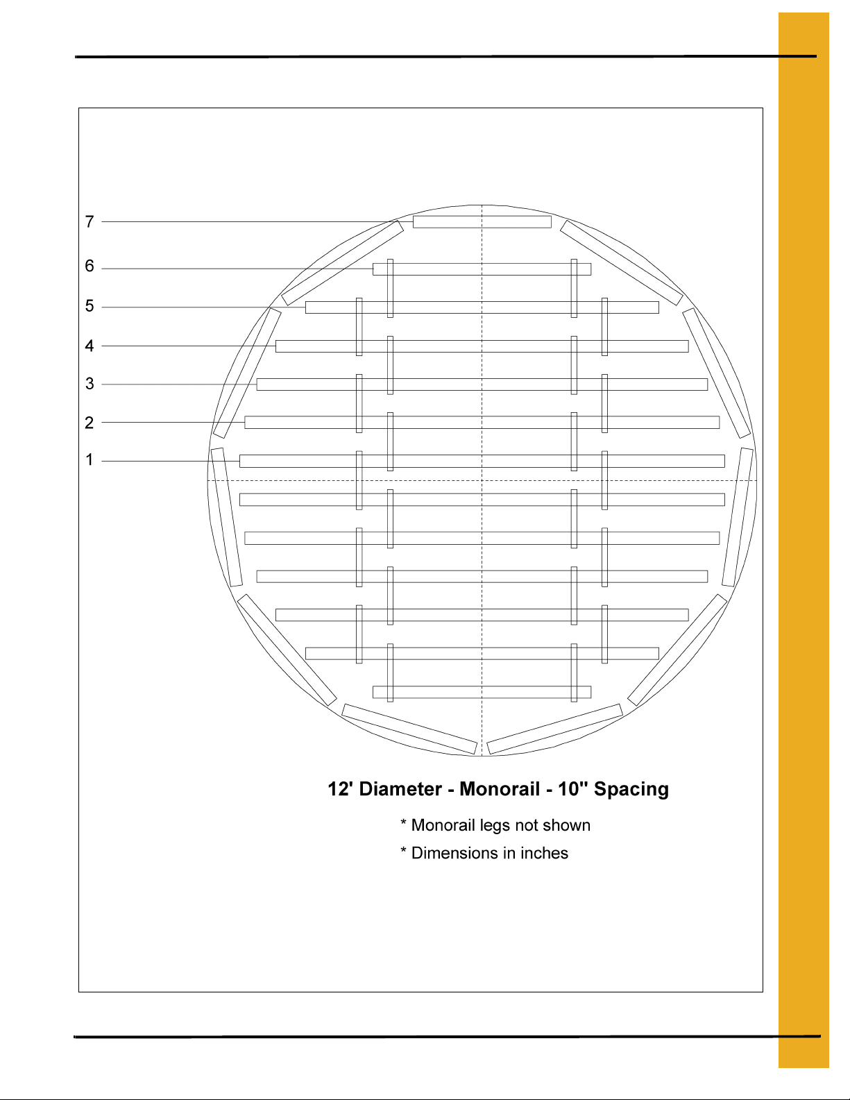
12' Bin Floor Layouts (Continued)
5. Layouts
Figure 5B
PNEG-225 Corrugated Floor and Monorail Layouts 21
Page 22
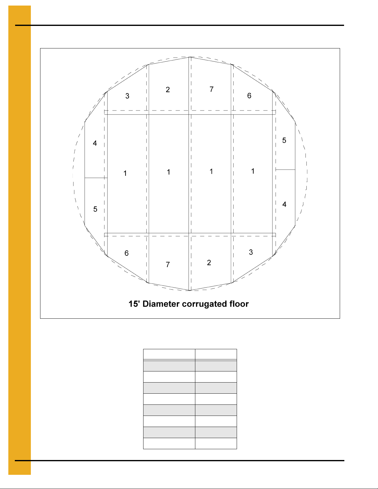
5. Layouts
15' Bin Floor Layouts
Figure 5C
15' Diameter Monorail Lengths
Monorail Number Sec 1
14 163
15 157
16 149
17 137
18 122
19 99
20 65
21 36
22 PNEG-225 Corrugated Floor and Monorail Layouts
Page 23
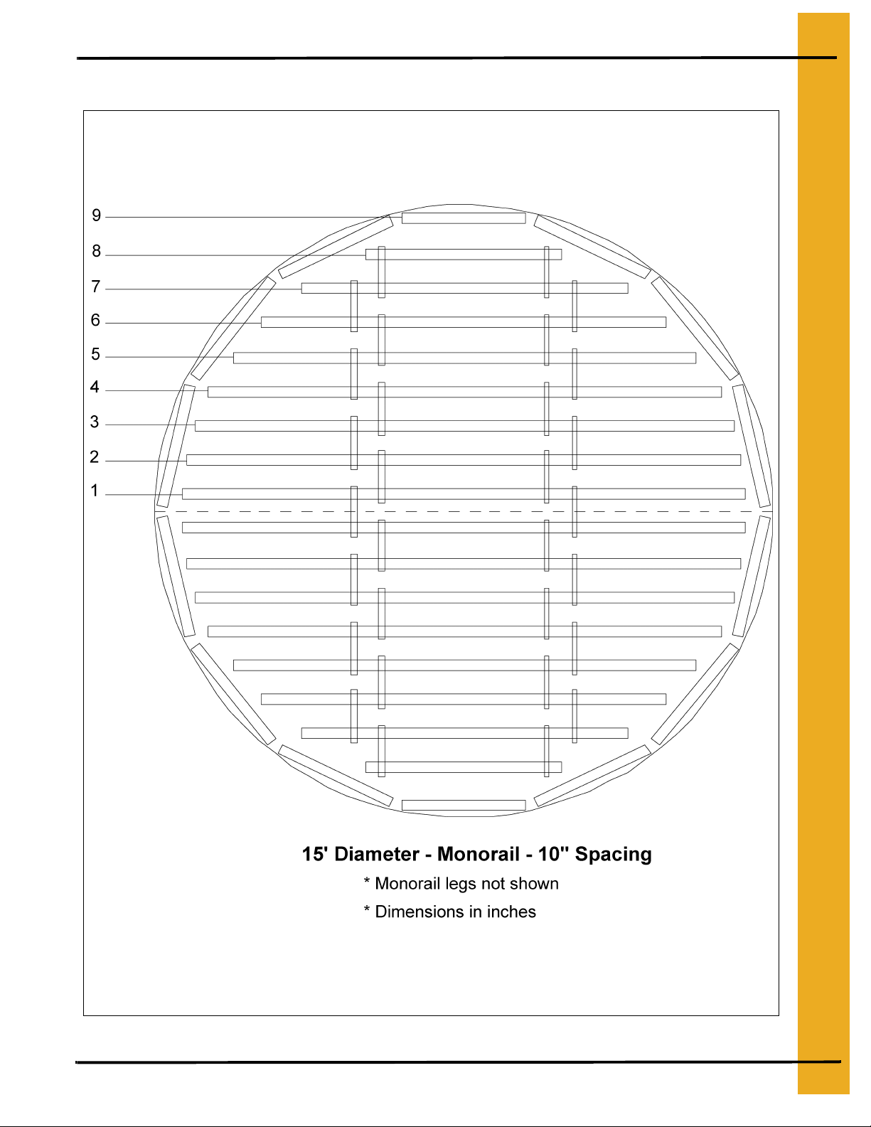
15' Bin Floor Layouts (Continued)
5. Layouts
Figure 5D
PNEG-225 Corrugated Floor and Monorail Layouts 23
Page 24
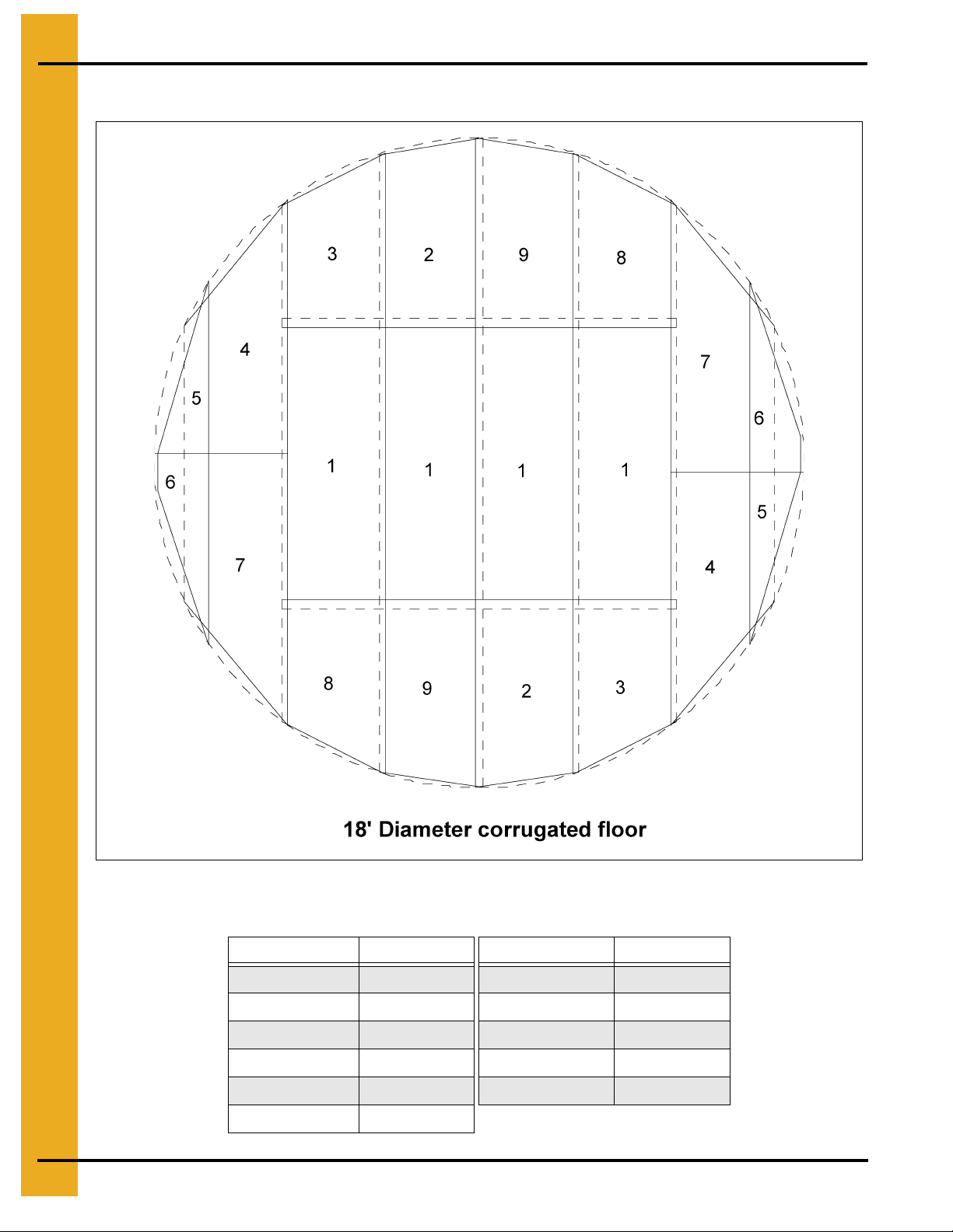
5. Layouts
18' Bin Floor Layouts
Figure 5E
18' Diameter Monorail Lengths
Monorail Number Sec 1 Monorail Number Sec 1
1 202 7 153
2 200 8 132
3 195 9 105
4 189 10 61
5 180 11 36
6 168
24 PNEG-225 Corrugated Floor and Monorail Layouts
Page 25

18' Bin Floor Layouts (Continued)
5. Layouts
Figure 5F
PNEG-225 Corrugated Floor and Monorail Layouts 25
Page 26

5. Layouts
20' Bin Floor Layouts
Figure 5G
20' Diameter Monorail Lengths
Monorail Number Sec 1 Monorail Number Sec 1
1 226 7 183
2 224 8 167
3 220 9 146
4 214 10 119
5 207 11 78
6 196 12 36
26 PNEG-225 Corrugated Floor and Monorail Layouts
Page 27

20' Bin Floor Layouts (Continued)
5. Layouts
Figure 5H
PNEG-225 Corrugated Floor and Monorail Layouts 27
Page 28

5. Layouts
21' Bin Floor Layouts
Figure 5I
21' Diameter Monorail Lengths
Monorail Number Sec 1 Monorail Number Sec 1
1 238 8 183
2 236 9 164
3 233 10 140
4 227 11 108
5 220 12 52
6 210 13 36
7 198
28 PNEG-225 Corrugated Floor and Monorail Layouts
Page 29

21' Bin Floor Layouts (Continued)
5. Layouts
Figure 5J
PNEG-225 Corrugated Floor and Monorail Layouts 29
Page 30

5. Layouts
24' Bin Floor Layouts
Figure 5K
24' Diameter Monorail Lengths
Monorail Number Sec 1 Sec 2 Monorail Number Sec 1 Sec 2
1 137 137 9 213 2 136 136 10 196 3 135 135 11 174 4 132 132 12 146 5 258 - 13 108 6 250 - 14 36 7 240 - 15 36 8 228 -
30 PNEG-225 Corrugated Floor and Monorail Layouts
Page 31

24' Bin Floor Layouts (Continued)
5. Layouts
Figure 5L
PNEG-225 Corrugated Floor and Monorail Layouts 31
Page 32

5. Layouts
25' Bin Floor Layouts
Figure 5M
25' Diameter Monorail Lengths
Monorail Number Sec 1 Sec 2 Monorail Number Sec 1 Sec 2
1 143 143 9 229 2 142 142 10 212 3 141 141 11 192 4 138 138 12 167 5 135 135 13 135 6 132 132 14 88 7 254 - 15 36 8 243 - 16 36 -
32 PNEG-225 Corrugated Floor and Monorail Layouts
Page 33

25' Bin Floor Layouts (Continued)
5. Layouts
Figure 5N
PNEG-225 Corrugated Floor and Monorail Layouts 33
Page 34

5. Layouts
27' Bin Floor Layouts
Figure 5O
27' Diameter Monorail Lengths
Monorail Number Sec 1 Sec 2 Monorail Number Sec 1 Sec 2
1 155 155 9 258 2 154 154 10 244 3 153 153 11 226 4 151 151 12 206 5 148 148 13 181 6 144 144 14 149 7 140 140 15 104 8 135 135 16 36 -
34 PNEG-225 Corrugated Floor and Monorail Layouts
Page 35

27' Bin Floor Layouts (Continued)
5. Layouts
Figure 5P
PNEG-225 Corrugated Floor and Monorail Layouts 35
Page 36

5. Layouts
30' Bin Floor Layouts
Figure 5Q
30' Diameter Monorail Lengths
Monorail Number Sec 1 Sec 2 Monorail Number Sec 1 Sec 2
1 172 172 10 144 144
2 172 172 11 137 137
3 170 170 12 257 4 168 168 13 237 5 167 167 14 214 6 164 164 15 186 7 160 160 16 150 8 155 155 17 98 9 150 150 18 36 -
36 PNEG-225 Corrugated Floor and Monorail Layouts
Page 37

30' Bin Floor Layouts (Continued)
5. Layouts
Figure 5R
PNEG-225 Corrugated Floor and Monorail Layouts 37
Page 38

5. Layouts
33' Bin Floor Layouts
Figure 5S
33' Diameter Monorail Lengths
Monorail Number Sec 1 Sec 2 Sec 3 Monorail Number Sec 1 Sec 2 Sec 3
1 59 264 59 11 159 159 2 58 264 58 12 152 152 3 57 264 57 13 143 143 4 56 264 56 14 134 134 5 53 264 53 15 246 - 6 51 264 51 16 220 - 7 47 264 47 17 189 - 8 43 264 43 18 148 - 9 38 264 38 19 87 - -
10 165 165 - 20 36 - -
38 PNEG-225 Corrugated Floor and Monorail Layouts
Page 39

33' Bin Floor Layouts (Continued)
5. Layouts
Figure 5T
PNEG-225 Corrugated Floor and Monorail Layouts 39
Page 40

5. Layouts
36' Bin Floor Layouts
Monorail Number Sec 1 Sec 2 Sec 3
36' Diameter Monorail Lengths
1 77 264 77
2 76 264 76
3 75 264 75
4 74 264 74
5 72 264 72
6 69 264 69
7 66 264 66
8 63 264 63
9 58 264 58
10 54 264 54
11 48 264 48
12 42 264 42
13 167 167 14 159 159 15 149 149 16 139 139 17 254 - 18 225 - 19 191 - 20 145 - 21 71 - 22 36 - -
40 PNEG-225 Corrugated Floor and Monorail Layouts
Page 41

36' Bin Floor Layouts (Continued)
5. Layouts
Figure 5U
PNEG-225 Corrugated Floor and Monorail Layouts 41
Page 42

5. Layouts
36' Bin Floor Layouts (Continued)
Figure 5V
42 PNEG-225 Corrugated Floor and Monorail Layouts
Page 43

39' Bin Floor Layouts
5. Layouts
Figure 5W
PNEG-225 Corrugated Floor and Monorail Layouts 43
Page 44

5. Layouts
39' Bin Floor Layouts (Continued)
39' Diameter Monorail Lengths
Monorail Number Sec 1 Sec 2 Sec 3
1 95 264 95
2 94 264 94
3 94 264 94
4 92 264 92
5 90 264 90
6 88 264 88
7 85 264 85
8 82 264 82
9 78 264 78
10 74 264 74
11 69 264 69
12 63 264 63
13 57 264 57
14 50 264 50
15 42 264 42
16 165 165 17 155 155 18 143 143 19 260 - 20 229 - 21 190 - 22 139 - 23 42 - 24 36 - -
44 PNEG-225 Corrugated Floor and Monorail Layouts
Page 45

39' Bin Floor Layouts (Continued)
5. Layouts
Figure 5X
PNEG-225 Corrugated Floor and Monorail Layouts 45
Page 46

5. Layouts
40' Bin Floor Layouts
Monorail Number Sec 1 Sec 2 Sec 3
1 101 264 101
2 100 264 100
3 100 264 100
4 98 264 98
5 96 264 96
6 94 264 94
7 91 264 91
8 88 264 88
9 84 264 84
10 80 264 80
11 75 264 75
40' Diameter Monorail Lengths
12 70 264 70
13 64 264 64
14 57 264 57
15 49 264 49
16 41 264 41
17 163 163 18 152 152 19 140 140 20 252 - 21 217 - 22 174 - 23 113 - 24 36 - 25 - -
46 PNEG-225 Corrugated Floor and Monorail Layouts
Page 47

40' Bin Floor Layouts (Continued)
5. Layouts
Figure 5Y
PNEG-225 Corrugated Floor and Monorail Layouts 47
Page 48

5. Layouts
40' Bin Floor Layouts (Continued)
Figure 5Z
48 PNEG-225 Corrugated Floor and Monorail Layouts
Page 49

42' Bin Floor Layouts
5. Layouts
Figure 5AA
PNEG-225 Corrugated Floor and Monorail Layouts 49
Page 50

5. Layouts
42' Bin Floor Layouts (Continued)
42' Diameter Monorail Lengths
Monorail Number Sec 1 Sec 2 Sec 3
1 101 264 101
2 100 264 100
3 100 264 100
4 98 264 98
5 96 264 96
6 94 264 94
7 91 264 91
8 88 264 88
9 84 264 84
10 80 264 80
11 75 264 75
12 70 264 70
13 64 264 64
14 57 264 57
15 49 264 49
16 41 264 41
17 163 163 18 152 152 19 140 140 20 252 - 21 217 - 22 174 - 23 113 - 24 36 - 25 - -
50 PNEG-225 Corrugated Floor and Monorail Layouts
Page 51

42' Bin Floor Layouts (Continued)
5. Layouts
Figure 5AB
PNEG-225 Corrugated Floor and Monorail Layouts 51
Page 52

5. Layouts
45' Bin Floor Layouts
Monorail Number Sec 1 Sec 2 Sec 3
1 131 264 131
2 130 264 130
3 130 264 130
4 128 264 128
5 127 264 127
6 125 264 125
7 122 264 122
8 120 264 120
9 116 264 116
10 113 264 113
11 108 264 108
45' Diameter Monorail Lengths
12 104 264 104
13 99 264 99
14 93 264 93
15 86 264 86
16 79 264 79
17 72 264 72
18 63 264 63
19 54 264 54
20 43 264 43
21 163 163 22 150 150 23 134 134 24 231 - 25 185 - 26 119 - 27 36 - -
52 PNEG-225 Corrugated Floor and Monorail Layouts
Page 53

45' Bin Floor Layouts (Continued)
5. Layouts
Figure 5AC
PNEG-225 Corrugated Floor and Monorail Layouts 53
Page 54

5. Layouts
45' Bin Floor Layouts (Continued)
Figure 5AD
54 PNEG-225 Corrugated Floor and Monorail Layouts
Page 55

48' Bin Floor Layouts
5. Layouts
Figure 5AE
PNEG-225 Corrugated Floor and Monorail Layouts 55
Page 56

5. Layouts
48' Bin Floor Layouts (Continued)
48' Diameter Monorail Lengths
Monorail Number Sec 1 Sec 2 Sec 3
1 149 264 149
2 148 264 148
3 148 264 148
4 147 264 147
5 145 264 145
6 143 264 143
7 141 264 141
8 138 264 138
9 135 264 135
10 132 264 132
11 128 264 128
12 124 264 124
13 119 264 119
14 114 264 114
15 108 264 108
16 101 264 101
17 94 264 94
18 87 264 87
19 78 264 78
20 69 264 69
21 59 264 59
22 47 264 47
23 166 166 24 152 152 25 135 135 26 231 - 27 180 - 28 104 - 29 36 - -
56 PNEG-225 Corrugated Floor and Monorail Layouts
Page 57

48' Bin Floor Layouts (Continued)
5. Layouts
Figure 5AF
Pneg-225 Corrugated Floor and Monorail Layouts 57
Page 58

5. Layouts
54' Bin Floor Layouts
Figure 5AG
58 Pneg-225 Corrugated Floor and Monorail Layouts
Page 59

54' Bin Floor Layouts (Continued)
54' Diameter Monorail Lengths
Monorail Number Sec 1 Sec 2 Sec 3 Sec 4
1 53 264 264 53
2 52 264 264 52
3 52 264 264 52
4 51 264 264 51
5 49 264 264 49
6 48 264 264 48
7 46 264 264 46
8 43 264 264 43
9 41 264 264 41
10 38 264 264 38
11 166 264 166 -
5. Layouts
12 163 264 163 13 158 264 158 14 154 264 154 15 149 264 149 16 143 264 143 17 138 264 138 18 131 264 131 19 124 264 124 20 117 264 117 21 108 264 108 22 99 264 99 23 90 264 90 24 79 264 79 25 67 264 67 26 54 264 54 27 40 264 40 28 155 155 - 29 136 136 - 30 225 - - 31 163 - - 32 42 - - 33 36 - - -
PNEG-225 Corrugated Floor and Monorail Layouts 59
Page 60

5. Layouts
54' Bin Floor Layouts (Continued)
Figure 5AH
60 PNEG-225 Corrugated Floor and Monorail Layouts
Page 61

60' Bin Floor Layouts
5. Layouts
Figure 5AI
PNEG-225 Corrugated Floor and Monorail Layouts 61
Page 62

5. Layouts
60' Bin Floor Layouts (Continued)
60' Diameter Monorail Lengths
Monorail Number Sec 1 Sec 2 Sec 3 Sec 4
1 89 264 264 89
2 88 264 264 88
3 88 264 264 88
4 87 264 264 87
5 86 264 264 86
6 84 264 264 84
7 82 264 264 82
8 80 264 264 80
9 78 264 264 78
10 75 264 264 75
11 72 264 264 72
12 69 264 264 69
13 65 264 264 65
14 61 264 264 61
15 57 264 264 57
16 52 264 264 52
17 47 264 264 47
18 41 264 264 41
19 167 264 167 20 161 264 161 21 154 264 154 22 146 264 146 23 138 264 138 24 130 264 130 25 120 264 120 26 110 264 110 27 99 264 99 28 87 264 87 29 74 264 74 30 59 264 59 31 43 264 43 32 156 156 - 33 134 134 - 34 213 - - 35 135 - - 36 36 - - -
62 PNEG-225 Corrugated Floor and Monorail Layouts
Page 63

60' Bin Floor Layouts (Continued)
5. Layouts
Figure 5AJ
Pneg-225 Corrugated Floor and Monorail Layouts 63
Page 64

5. Layouts
72' Bin Floor Layouts
Figure 5AK
64 Pneg-225 Corrugated Floor and Monorail Layouts
Page 65

72' Bin Floor Layouts (Continued)
72' Diameter Monorail Lengths
Monorail Number Sec 1 S ec 2 S ec 3 Sec 4
1 160 264 264 160
2 160 264 264 160
3 160 264 264 160
4 159 264 264 159
5 158 264 264 158
6 157 264 264 157
7 155 264 264 155
8 153 264 264 153
9 151 264 264 151
10 149 264 264 149
11 147 264 264 147
12 144 264 264 144
13 141 264 264 141
14 138 264 264 138
15 134 264 264 134
16 130 264 264 130
17 126 264 264 126
18 122 264 264 122
19 117 264 264 117
20 112 264 264 112
21 107 264 264 107
22 101 264 264 101
23 95 264 264 95
24 88 264 264 88
25 81 264 264 81
26 74 264 264 74
27 66 264 264 66
28 58 264 264 58
29 49 264 264 49
30 40 264 264 40
31 162 264 162 32 151 264 151 33 139 264 139 34 127 264 127 35 113 264 113 36 98 264 98 37 82 264 82 38 64 264 64 39 44 264 44 40 152 152 - 41 246 - - 42 166 - - 43 36 - - -
5. Layouts
PNEG-225 Corrugated Floor and Monorail Layouts 65
Page 66

5. Layouts
72' Bin Floor Layouts (Continued)
Figure 5AL
66 PNEG-225 Corrugated Floor and Monorail Layouts
Page 67

75' Bin Floor Layouts
5. Layouts
Figure 5AM
PNEG-225 Corrugated Floor and Monorail Layouts 67
Page 68

5. Layouts
75' Bin Floor Layouts (Continued)
75' Diameter Monorail Lengths
Monorail Number Sec 1 Sec 2 Sec 3 Sec 4 Sec 5
1 46 264 264 264 46
2 46 264 264 264 46
3 45 264 264 264 45
4 45 264 264 264 45
5 44 264 264 264 44
6 43 264 264 264 43
7 41 264 264 264 41
8 40 264 264 264 40
9 38 264 264 264 38
10 36 264 264 264 36
11 165 264 264 165 12 163 264 264 163 13 160 264 264 160 14 157 264 264 157 15 153 264 264 153 16 150 264 264 150 17 146 264 264 146 18 142 264 264 142 19 137 264 264 137 20 132 264 264 132 21 127 264 264 127 22 122 264 264 122 23 116 264 264 116 24 110 264 264 110 25 103 264 264 103 26 96 264 264 96 27 89 264 264 89 28 81 264 264 81 29 73 264 264 73 30 64 264 264 64 31 55 264 264 55 32 45 264 264 45 33 166 264 166 - 34 155 264 155 - 35 143 264 143 - 36 130 264 130 - 37 116 264 116 - 38 100 264 100 - 39 83 264 83 - 40 64 264 64 - 41 43 264 43 - 42 150 150 - - 43 237 - - - 44 147 - - - 45 36 - - - -
68 PNEG-225 Corrugated Floor and Monorail Layouts
Page 69

75' Bin Floor Layouts (Continued)
5. Layouts
Figure 5AN
Pneg-225 Corrugated Floor and Monorail Layouts 69
Page 70

5. Layouts
78' Bin Floor Layouts
Figure 5AO
70 Pneg-225 Corrugated Floor and Monorail Layouts
Page 71

78' Bin Floor Layouts (Continued)
78' Diameter Monorail Lengths
Monorail Number Sec 1 Sec 2 Sec 3 Sec 4 Sec 5
1 64 264 264 264 64
2 64 264 264 264 64
3 63 264 264 264 63
4 63 264 264 264 63
5 62 264 264 264 62
6 61 264 264 264 61
7 59 264 264 264 59
8 58 264 264 264 58
9 56 264 264 264 56
10 54 264 264 264 54
11 52 264 264 264 52
12 49 264 264 264 49
13 46 264 264 264 46
14 43 264 264 264 43
15 40 264 264 264 40
16 37 264 264 264 37
17 165 264 264 165 18 161 264 264 161 19 157 264 264 157 20 152 264 264 152 21 147 264 264 147 22 142 264 264 142 23 137 264 264 137 24 131 264 264 131 25 125 264 264 125 26 118 264 264 118 27 111 264 264 111 28 104 264 264 104 29 96 264 264 96 30 88 264 264 88 31 79 264 264 79 32 70 264 264 70 33 60 264 264 60 34 50 264 264 50 35 39 264 264 39 36 159 264 159 - 37 147 264 147 - 38 133 264 133 - 39 118 264 118 - 40 102 264 102 - 41 84 264 84 - 42 64 264 64 - 43 41 264 41 - 44 147 147 - - 45 226 - - - 46 122 - - - 47 36
5. Layouts
PNEG-225 Corrugated Floor and Monorail Layouts 71
Page 72

5. Layouts
78' Bin Floor Layouts (Continued)
Figure 5AP
72 PNEG-225 Corrugated Floor and Monorail Layouts
Page 73

90' Bin Floor Layouts
5. Layouts
Figure 5AQ
PNEG-225 Corrugated Floor and Monorail Layouts 73
Page 74

5. Layouts
90' Bin Floor Layouts (Continued)
90' Diameter Monorail Lengths
Monorail Number Sec 1 Sec 2 Sec 3 Sec 4 Sec 5
1 136 264 264 264 136
2 136 264 264 264 136
3 135 264 264 264 135
4 135 264 264 264 135
5 134 264 264 264 134
6 133 264 264 264 133
7 132 264 264 264 132
8 130 264 264 264 130
9 129 264 264 264 129
10 127 264 264 264 127
11 125 264 264 264 125
12 123 264 264 264 123
13 121 264 264 264 121
14 118 264 264 264 118
15 115 264 264 264 115
16 112 264 264 264 112
17 109 264 264 264 109
18 106 264 264 264 106
19 102 264 264 264 102
20 98 264 264 264 98
21 94 264 264 264 94
22 90 264 264 264 90
23 85 264 264 264 85
24 80 264 264 264 80
25 75 264 264 264 75
26 70 264 264 264 70
27 64 264 264 264 64
28 58 264 264 264 58
29 52 264 264 264 52
30 46 264 264 264 46
31 39 264 264 264 39
32 163 264 264 163 33 156 264 264 156 34 148 264 264 148 35 140 264 264 140 36 131 264 264 131 37 122 264 264 122 38 112 264 264 112 39 102 264 264 102 40 91 264 264 91 41 79 264 264 79 42 67 264 264 67 43 54 264 264 54 44 40 264 264 40 45 157 264 157 - 46 141 264 141 - 47 124 264 124 - 48 105 264 105 - 49 83 264 83 - 50 59 264 59 - 51 163 163 - - 52 257 - - - 53 156 - - - 54 36 - - - -
74 PNEG-225 Corrugated Floor and Monorail Layouts
Page 75

90' Bin Floor Layouts (Continued)
5. Layouts
Figure 5AR
Pneg-225 Corrugated Floor and Monorail Layouts 75
Page 76

5. Layouts
105' Bin Floor Layouts
Figure 5AS
76 Pneg-225 Corrugated Floor and Monorail Layouts
Page 77

105' Bin Floor Layouts (Continued)
105' Diameter Monorail Lengths
Monorail Number Sec 1 Sec 2 Sec 3 Sec 4 Sec 5 Sec 6
1 93 264 264 264 264 93
2 93 264 264 264 264 93
3 93 264 264 264 264 93
4 92 264 264 264 264 92
5 92 264 264 264 264 92
6 91 264 264 264 264 91
7 90 264 264 264 264 90
8 89 264 264 264 264 89
9 87 264 264 264 264 87
10 86 264 264 264 264 86
11 84 264 264 264 264 84
12 82 264 264 264 264 82
13 80 264 264 264 264 80
14 78 264 264 264 264 78
15 76 264 264 264 264 76
16 73 264 264 264 264 73
17 71 264 264 264 264 71
18 68 264 264 264 264 68
19 65 264 264 264 264 65
20 62 264 264 264 264 62
21 58 264 264 264 264 58
22 54 264 264 264 264 54
23 51 264 264 264 264 51
24 47 264 264 264 264 47
25 42 264 264 264 264 42
26 38 264 264 264 264 38
27 165 264 264 264 165 28 161 264 264 264 161 29 155 264 264 264 155 30 150 264 264 264 150 31 145 264 264 264 145 32 139 264 264 264 139 33 133 264 264 264 133 34 126 264 264 264 126 35 120 264 264 264 120 36 113 264 264 264 113 37 106 264 264 264 106 38 98 264 264 264 98 39 91 264 264 264 91 40 83 264 264 264 83 41 74 264 264 264 74 42 65 264 264 264 65 43 56 264 264 264 56 44 46 264 264 264 46 45 36 264 264 264 36 46 158 264 264 158 - 47 147 264 264 147 - 48 135 264 264 135 - 49 123 264 264 123 - 50 110 264 264 110 - 51 96 264 264 96 - 52 82 264 264 82 - 53 66 264 264 66 - 54 50 264 264 50 - 55 164 264 164 - - 56 145 264 145 - - 57 124 264 124 - - 58 101 264 101 - - 59 74 264 74 - - 60 43 264 43 - - 61 137 137 - - - 62 162 - - - - 63 36
5. Layouts
PNEG-225 Corrugated Floor and Monorail Layouts 77
Page 78

5. Layouts
105' Bin Floor Layouts (Continued)
Figure 5AT
78 PNEG-225 Corrugated Floor and Monorail Layouts
Page 79

Limited Warranty
The GSI Group, LLC. (“GSI”) warrants products which it manufactures to be free of defects in materials
and workmanship under normal usage and conditions for a period of 12 months after sale to the original
end-user or if a foreign sale, 14 months from arrival at port of discharge, whichever is earlier. The enduser’s sole remedy (and GSI’s only obligation) is to repair or replace, at GSI’s option and expense,
products that in GSI’s judgment, contain a material defect in materials or workmanship. Expenses
incurred by or on behalf of the end-user without prior written authorization from the GSI Warranty Group
shall be the sole responsibility of the end-user.
Warranty Extensions: The Limited Warranty period is extended for the following products:
Product Warranty Period
AP Fans and
Flooring
Cumberland
Feeding/Watering
Systems
Grain Systems
Grain Systems
Farm Fans
Zimmerman
Performer Series Direct Drive
Fan Motor
All Fiberglass Housings Lifetime
All Fiberglass Propellers Lifetime
Feeder System Pan Assemblies 5 Years **
Feed Tubes (1.75" & 2.00") 10 Years *
Centerless Augers 10 Years *
Watering Nipples 10 Years *
Grain Bin Structural Design 5 Years
Portable & Tower Dryers 2 Years
Portable & Tower Dryer Frames
and Internal Infrastructure †
3 Years
5 Years
GSI further warrants that the portable and tower dryer frame and basket, excluding all auger and auger
drive components, shall be free from defects in materials for a period of time beginning on the twelfth (12
month from the date of purchase and continuing until the sixtieth (60
th
) month from the date of purchase
* Warranty prorated from list price:
0 to 3 years – no cost to end-user
3 to 5 years – end-user pays 25%
5 to 7 years – end-user pays 50%
7 to 10 years – end user pays 75%
** Warranty prorated from list price:
0 to 3 years – no cost to end-user
3 to 5 years – end-user pays 50%
† Motors, burner components and
moving parts not included. Portable
Dryer screens included. Tower Dryer
screens not included.
th
)
(extended warranty period). During the extended warranty period, GSI will replace the frame or basket
components that prove to be defective under normal conditions of use without charge, excluding the labor,
transportation, and/or shipping costs incurred in the performance of this extended warranty.
Conditions and Limitations:
THERE ARE NO WARRANTIES THAT EXTEND BEYOND THE LIMITED WARRANTY DESCRIPTION
SET FORTH ABOVE. SPECIFICALLY, GSI MAKES NO FURTHER WARRANTY OF ANY KIND,
EXPRESS OR IMPLIED, INCLUDING, WITHOUT LIMITATION, WARRANTIES OF MERCHANTABILITY
OR FITNESS FOR A PARTICULAR PURPOSE OR USE IN CONNECTION WITH: (i) PRODUCT
MANUFACTURED OR SOLD BY GSI OR (ii) ANY ADVICE, INSTRUCTION, RECOMMENDATION OR
SUGGESTION PROVIDED BY AN AGENT, REPRESENTATIVE OR EMPLOYEE OF GSI REGARDING
OR RELATED TO THE CONFIGURATION, INSTALLATION, LAYOUT, SUITABILITY FOR A PARTICULAR
PURPOSE, OR DESIGN OF SUCH PRODUCTS.
GSI shall not be liable for any direct, indirect, incidental or consequential damages, including, without
limitation, loss of anticipated profits or benefits. The sole and exclusive remedy is set forth in the Limited
Warranty, which shall not exceed the amount paid for the product purchased. This warranty is not
transferable and applies only to the original end-user. GSI shall have no obligation or responsibility for any
representations or warranties made by or on behalf of any dealer, agent or distributor.
GSI assumes no responsibility for claims resulting from construction defects or unauthorized modifications
to products which it manufactured. Modifications to products not specifically delineated in the manual
accompanying the equipment at initial sale will void the Limited Warranty.
This Limited Warranty shall not extend to products or parts which have been damaged by negligent use,
misuse, alteration, accident or which have been improperly/inadequately maintained. This Limited Warranty
extends solely to products manufactured by GSI.
Prior to installation, the end-user has the responsibility to comply with federal, state and local codes which
apply to the location and installation of products manufactured or sold by GSI.
9101239_1_CR_rev7.DOC (revised July 2009)
Page 80

This equipment shall be installed in accordance with
the current installation codes and applicable
regulations which should be carefully followed in all
cases. Authorities having jurisdiction should be
consulted before installations are made.
Copyright © 2008 by GSI Group
Printed in the USA
GSI Group
1004 E. Illinois St.
Assumption, IL 62510-0020
Phone: 1-217-226-4421
Fax: 1-217-226-4420
www.gsiag.com
 Loading...