

Page 1
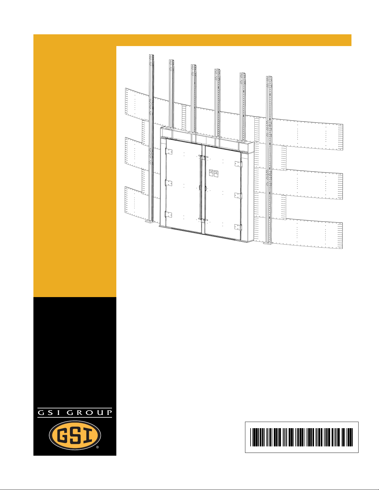
VTDL-72-8X9D - VTDL-78-8X9D
Door
Assembly Instructions
PNEG-1336D
Date: 05-14-08
PNEG-1336D
Page 2

2 PNEG-1336D VTDL-72-8X9D - VTDL-78-8X9D Door
Page 3

Table of Contents
Contents
Chapter 1 Introduction ........................................................................................................................................ 4
Chapter 2 Safety ..................................................................................................................................................5
Safety Guidelines ............................................................................................................................... 5
General Safety Statement ................................................................ ... ... .... ... ... ... ............................... 6
Safety Instructions .............................................................................................................................. 7
Safety Sign-Off Sheet ......................................................................................................................... 9
Proper Storage Grain Bin/Silo Materials Prior to Construction ......................................................... 10
Chapter 3 Safety Decals ...................................................................................................................................11
Chapter 4 Assembly Instructions ....................................................................................................................14
Chapter 5 Door Assembly ................................................................................................................................17
Sidewall and Stiffener Layout ........................................................................................................... 17
Door Assembly Exploded View ........................................................................................................ 18
Column Installation ........................................................................................................................... 19
Header Beam Installation ................................................................................................................. 20
Header Beam Connection Details .................................................................................................... 21
Center Column Installation ............................................................................................................... 22
Door Panel Assembly ....................................................................................................................... 23
Door Panel Assembly (2) ................................................................................................................. 24
Stiffener/SDW Attachment ............................................................................................................... 25
Weld Details ................................. .... ... ... ... .......................................... ... .......................................... 26
Outer Cover Assembly ..................................................................................................................... 27
VTDL Door Foundation Note ............................... ................................................ ............................. 29
Chapter 6 Warranty ...........................................................................................................................................33
PNEG-1336D VTDL-72-8X9D - VTDL-78-8X9D Door 3
Page 4

1. Introduction
READ THIS MANUAL carefully to learn how to properly use and install equipment. Failure to do so could
result in personal injury or equipment damage.
INSPECT the shipment immediately upon arrival. The customer is responsible for ensuring that all
quantities are correct. The customer should report and note any damage or shortage on the bill of
lading to justify their claim to the transport company.
THIS MANUAL SHOULD BE CONSIDERED a permanent part of your equipment and should be easily
accessible when needed.
This warranty provides you the assurance that the company will back its products when defects appear
within the warranty period. In some circumstances, the company also provide s field improvements, often
without charge to the customer, even if the product is out of warranty. Should the equipment be abused,
or modified to change its performance beyond the factory specifications, the warranty will be come void
and field improvements may be denied.
4 PNEG-1336D VTDL-72-8X9D - VTDL-7 8-8X9 D Door
Page 5
2. Safety
Safety Guidelines
This manual contains information that is important for you, the owner/operator, to know and understand.
This information relates to protecting personal safety and preventing equipment problems. It is the
responsibility of the owner/operator to inform anyone operating or working in the area of this equipment
of these safety guidelines. To help you recognize this information, we use the symbols that are defined
below. Please read the manual and pay attention to these sections. Failure to read this manual and its
safety instructions is a misuse of the equipment and may lead to serious injury or death.
This is the safety alert symbol. It is used to alert you to
potential personal injury hazards. Obey all safety
messages that follow this symbol to avoid possible
injury or death.
DANGER indicates an imminently hazardous situation
which, if not avoided, will result in death or serious injury.
WARNING indicates a potentially hazardous situation
which, if not avoided, could result in death or serious injury.
CAUTION indicates a potentially hazardous situation which,
if not avoided, may result in minor or moderate injury.
CAUTION used without the safety alert symbol indicates a
potentially hazardous situation which, if not avoided, may
result in property damage.
NOTE indicates information about the equipment that you
should pay special attention.
PNEG-1336D VTDL-72-8X9D - VTDL-78-8X9D Door 5
Page 6
2. Safety
General Safety Statement
Our foremost concern is your safety and the safety of others associated with grain handling equipment.
This manual is to help you understand safe operating procedures and some problems which may be
encountered by the operator and other personnel.
As owner and/or operator, you are responsible to know what requirements, hazards and precautions
exist and inform all personnel associated with the equipment or in the area. Safety precautions may be
required from the personnel. Avoid any alterations to the equipment, which may produce a very
dangerous situation, where serious injury or death may occur.
You should consider the location of the bin site relative to power line locations or electrical transmission
equipment. Contact your local power company to review your installation plan or for information
concerning required equipment clearance. Clearance of portable equip ment that may be taken to the bin
site should also be reviewed and considered. Any electrical control equipment in contact with the bin
should be properly grounded and installed in accordance with National Electric Code provisions and
other local or national codes.
This product is intended for the use of grain storage only. Any other use is a misuse of the product.
This product has sharp edges, which may cause serious injury. To avoid injury, handle
sharp edges with caution and always use proper protective clothing and equipment.
Sidewall bundles or sheets must be stored in a safe manner. The safest method of storing sidewall
bundles is laying horizontally with the arch of the sheet upward, like a dome. Sidewall sheets stored on
edge must be secured so that they cannot fall over and cause injury. Use care when handling and
moving sidewall bundles.
Personnel operating or working around equipment should read this manual. This manual must be
delivered with equipment to its owner. Failure to read this manual and its safety instructions is a misuse
of the equipment.
6 PNEG-1336D VTDL-72-8X9D - VTDL-78-8X9D Door
Page 7
2. Safety
Safety Instructions
Our foremost concern is your safety and the safety of others associated with this equipment. We want
to keep you as a customer. This manual is to help you understand safe operating proced ures and some
problems which may be encountered by the operator and other personnel.
As owner and/or operator, it is your responsibility to know what requirements, hazards and precautions
exist, and to inform all personnel associated with the equipment or in the area. Safety precautions may
be required from the personnel. Avoid any alterations to the equipment. Such alterations may produce
a very dangerous situation where SERIOUS INJURY or DEATH may occur.
This equipment shall be installed in accordance with the current installation codes and applicable
regulations which should be carefully followed in all cases. Authorities having jurisdiction should be
consulted before installations are made.
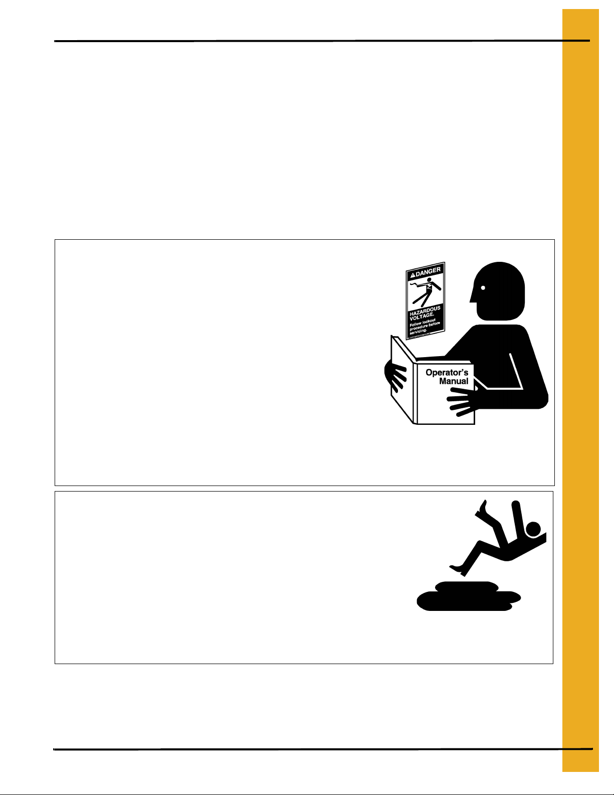
Follow Safety Instructions
Carefully read all safety messages in this manual and
safety signs on your machine. Keep signs in good
condition. Replace missing or damaged safety signs. Be
sure new equipment components and repair parts include
the current safety signs. Replacement safety signs are
available from the manufacturer.
Learn how to operate the machine and how to use controls
properly. Do not let anyone operate without instruction.
Keep your machinery in proper working condition.
Unauthorized modifications to the machine may impair
the function and/or safety and affect machine life.
If you do not understand any part of this manual or need
assistance, contact your dealer.
Practice Safe Maintenance
Understand service procedures before doing work. Keep area
clean and dry.
Never lubricate, service, or adjust machine while it is in operation.
Keep hands, feet and clothing away from rotating parts.
Keep all parts in good condition and properly installed. Fix
damage immediately . Replace worn or broken p arts. Remove any
built up grease oil and debris.
Read and Understand Manual
Maintain Equipment
and Work Area
PNEG-1336D VTDL-72-8X9D - VTDL-78-8X9D Door 7
Page 8
2. Safety
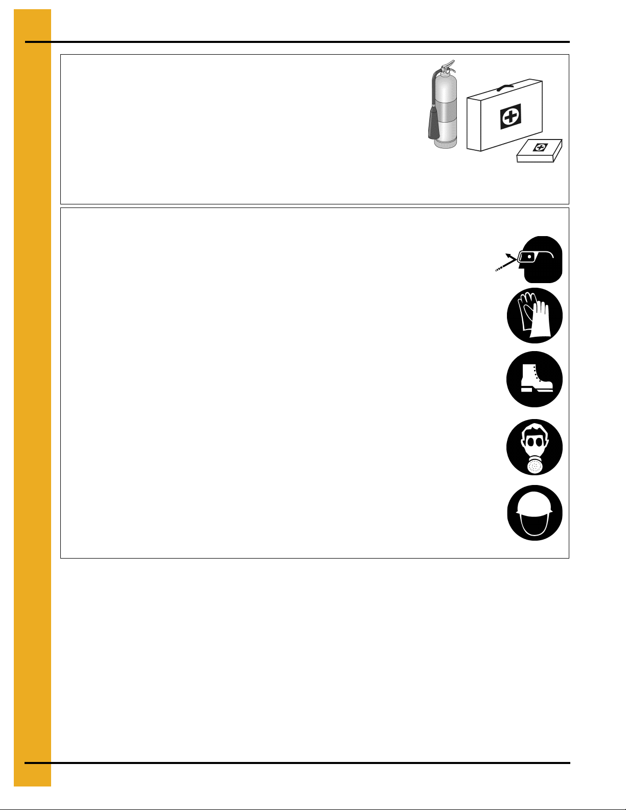
Prepare for Emergencies
Be prepared if fire starts.
Keep a first aid kit and fire extinguisher handy.
Keep emergency numbers for doctors, ambulance service,
hospital and fire department near your telephone.
Wear Protective Clothing
Wear close fitting clothing and safety equipment appropriate
to the job.
Remove all jewelry.
Keep Emergency Equipment
Quickly Accessible
Eye Protection
Long hair should be tied up and back.
Safety glasses should be worn at all times to protect eyes
from debris.
Wear gloves to protect your hands from sharp edges on
plastic or steel parts.
Wear steel toe boots to help protect your feet from falling
debris. Tuck in any loose or dangling shoe strings.
A respirator may be needed to prevent breathing potentially
toxic fumes and dust.
Wear hard hat to help protect your head.
Gloves
Steel Toe Boots
Respirator
Hard Hat
8 PNEG-1336D VTDL-72-8X9D - VTDL-78-8X9D Door
Page 9

2. Safety
Safety Sign-Off Sheet
As a requirement of O.S.H.A., it is necessary for the employer to train the employee in the safe operating
and safety procedures for this auger. This sign-off sheet is provided for your convenience and personal
record keeping. All unqualified persons are to stay out of the work area at all times. It is strongly
recommended that another qualified person who knows the shut down procedure be in the area in the
event of an emergency.
Date Employee Name Supervisor Name
PNEG-1336D VTDL-72-8X9D - VTDL-78-8X9D Door 9
Page 10

2. Safety
Proper Storage Grain Bin/Silo Materials Prior to Construction
Wet storage stain (rust) will develop when closely packed bundles of galvanized material, such as
sidewall and roof sheets, have moisture present. Inspect roof and sidewall bundles on arrival for any
moisture. If moisture is present, it must not be allowed to remain between the sheets. Separate the
sheets or panels immediately and wipe them down. Spray with a light oil or diesel fuel.
If possible, sidewall bundles, roof sheets and other closely packed galvanized materials should be stored
in a dry, climate controlled building. If outdoor storage is unavoidable, the materials should be stored so
that they are raised above the ground and vegetation. Any tacking and spacing materia ls should not be
corrosive or wet. Be sure to protect materials from the weather, but permit air movement around the
bundles if possible.
Storing roof bundles and sidewall sheets at a slight incline can also help minimize the presence of
moisture. Storing the bundles with the center of the dome up (like an arch) is one option for minimizing
moisture during storage. Sidewall bundles can also be stored on edge but must be secured so that they
do not fall over and cause injury.
If “white rust” or “wet storage stain” occurs, contact the manufacturer immediately about ways to
minimize the adverse effect upon the galvanized coating.
10 PNEG-1336D VTDL-72-8X9D - VTDL-78-8X9D Door
Page 11
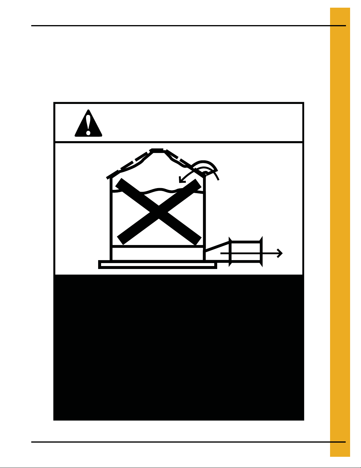
3. Safety Decals
The manufacturer does not warrant any roof damage caused by excessive vacuum or internal
pressure from fans or other air moving systems. Adequate ventilation and/or “makeup air”
devices should be provided for all powered air handling systems. The manufacturer does not
recommend the use of downward flow systems (suction). Severe roof damage can result from
any blockage of air passages. Running fans during high humidity/cold weather conditions can
cause air exhaust or intake ports to freeze.
CAUTION!
Excessive vacuum (or pressure) may
damage roof. Use positive aeration
system. Make sure all roof vents are
open and unobstructed. Start roof
fans when supply fans are started.
Do not operate when conditions exist
that may cause roof vent icing.
DC-969
PNEG-1336D VTDL-72-8X9D - VTDL-78-8X9D Door 11
Page 12

3. Safety Decals
ATTENTION: The decal shown below should be present on the outside of the door cover of the
2 ring, 24" porthole door cover and the roof manway cover. If a decal has been damaged or is missing
in any of these locations, contact the manufacturer for a free replacement decal.
GSI Decals
1004 E. Illinois St.
Assumption, IL. 62510
Phone: 217-226-4421
Rotating flighting will
kill or dismember.
Flowing material will
trap and suffocate.
Crusted material will
collapse and suffocate.
Keep clear of all augers.
DO NOT ENTER this bin!
If you must enter the bin:
1. Shut off and lock out all power.
2. Use a safety harness and safety line.
3. Station another person outside the bin.
4. Avoid the center of the bin.
5. Wear proper breathing equipment or respirator.
Failure to heed these
warnings will result in
serious injury or death.
DC-GBC-1A
12 PNEG-1336D VTDL-72-8X9D - VTDL-78-8X9D Door
Page 13

3. Safety Decals
ATTENTION: The decal shown below should be present on the outside of the door cover of the
2 ring, 24" porthole door cover and the roof manway cover. If a decal has been damaged or is missing
in any of these locations, contact the manufacturer for a free replacement decal.
GSI Decals
1004 E. Illinois St.
Assumption, IL. 62510
Phone: 217-226-4421
WARNIN
DON’T
DO
UNLOADING INSTRUCTIONS:
1. Use CENTER FLOOR OUTLET ONLY until NO grain
remains above this outlet.
2. Side floor outlets to be used ONLY when above
condition is satisfied.
3. Lock all side floor outlets to avoid accidental
premature use.
4. See manufacturers instructions for proper use of
factory supplied sidedraw (wall) discharge systems.
Failure to heed these warnings
could result in serious injury, death,
structural damage or collapse of tank.
DC-GBC-2A
PNEG-1336D VTDL-72-8X9D - VTDL-78-8X9D Door 13
Page 14

4. Assembly Instructions
Written Instructions for Installation of a VTDL-72-8X9D - VTDL-78-8X9D
Large Vehicle Traffic Door in 72'-78' Diameter, Externally Stiffened Tanks
Prior to door installation, tank should be fully erected and anchored. The VTDL door is to be installed in
the bottom 4 rings of the tank. Adequate provisions should be made for door installation. A list of
necessary tools and equipment is attached. Also some field fabrication and welding will be necessary.
1. The VTDL door is to be installed in the bottom 4 rings of the tank.
2. The door must be placed near an intermediate discharge well such that grain will clear away from
the door panels when tank is emptied.
3. Tank erection will be done as normal until the fifth ring from the bottom is to be installed. The fifth
ring will be installed as normal except that the orientation of the sidewall sheets should match the
sidewall layout shown on Page 17. At door location, install special punched, special length door
sheets at the correct position as shown on Page 17. Use two (2) non-laminated sidewall sheets
(minimum 12 gauge) per ring without caulk to temporarily complete the ring. Use only horizontal
seam bolts to connect the filler sheets to the door sheets. Continue installing the sidewall as normal
except for installing the special door sheets and temporary sheets. These sheets are used as filler
sheets to keep the tank round until fully erected. They will be removed prior to door installation.
Also four (4) sets of stiffeners should be omitted at the door location. (See Page 17.) Stan dard base
stiffener weldments will be used in these locations after doorframe is completely installed. Anchor
tank securely before installing door.
4. When tank is properly anchored, remove filler sheets. Be sure the sidewall is installed as shown
on Page 17.
5. Review Pages 18 and 27 to identify doorframe and outer cover parts.
6. Place threshold weldments (VTDL-0381 and VTDL-0382) in door opening between sidewall sheets.
Install left and right column weldments (VTDL-0375 and VTDL-0380) as shown
column weldments to sidewall sheets with 3/8" x 1-1/2" bolts (S-5060) and 3/8" nuts (S-456).
NOTE:
(
corrugated sealing strips onto the outer edge of the sidewall sheets and the inner edge of the
sidewall attachment plates. Caulk around seal strip as well. Align edge of column base plate with
edge of threshold weldment. Also the door panel attachment strips of the columns and threshold
must be aligned.
anchored with 3/4" epoxy type anchors or by field welding to tunnel girder. The column weldments
must be field welded to the threshold weldme nts. Do no t anch or or weld until d oor is fully installe d.
7. Install header beam weldment (VTDL-0370 for 72' and VTDL-0530 for 78 ') on the top of the column
weldments. The header beam weldment will slide onto the top of the columns from the inside of the
tank. Fasten loosely with 1" x 3-1/2" Grade 8 bolts (S-7622), 1" washers (S-7623) and 1" nuts
(S-240). See detail A on Page 21. Be sure that the sidewall attachment plate holes of the header
and column are aligned. Attach the sidewall of the fifth ring to the header seal strip with
3/8" x 1-1/2" bolts. Do not tighten bolts until door panels are installed.
Bolt size may change slightly with gauge changes.) Do not tighten bolts at this time. Insert
(See Page 19 and Page 21.)
The columns and threshold weldments will be
on Page 19
. Fasten
14 PNEG-1336D VTDL-72-8X9D - VTDL-78-8X9D Door
Page 15

4. Assembly Instructions
8. The center column weldments (VTDL-0383) will be installed within the doorframe. The bottom of
the center column weldment will rest between the column outer cover strip on the threshold
weldment. The top of the center column weldment will bolt to the header beam weldment with
1" x 3-1/2" bolts. See details B and C
column and header beam and threshold weldment. Place one (1) shim plate on the threshold
weldment splice prior to the placement of the center column. The center column should be placed
inside of the tank with the base of the column near the threshold weldment splice. Tilt the column
upward into position and bolt it to the header beam. Install the top shim plate. The door panel
attachment plates of the column, header and threshold weldments sh o uld be align ed.
(See Page 22.)
center column. Do not tighten bolts until door panels are installed.
9. Verify that the doorframe is square and all door panel attachment plates are in alignment prior to
installing door panels.
10. Assemble door panels as shown on Page 23. Door panels must be installed in this manner to
maintain proper orientation of hinges. Door hinge plate weldments (VTDL-0391) are to be placed
as shown on Page 23 detail D. Use 3/8" x 1" bin bolts at door panel splices and 3/8" x 1-1/2" bolts
at hinge plate weldments. Bolt head with sealing washer should be on the outside for all splice
connections and on the inside for all hinge weldment connections. Follow installation details
on Page 24 for door panel placement. Use 1" x 2-1/2" Grade 8 bolts to attach door panels to the
doorframe. 1" x 3-1/2" Grade 8 bolts will be used at hinge location. Use only enough bolts to hold
panels in place and clamp the panels to the doorframe. Be sure that the panels are closed
completely and all holes are aligned. The door panels will be opened later to allow for field welding
and sealing. Caulk all along door panel splices.
The center column is to be removed when door is opened; do not field weld to
on Page 22
. Use VTDL-0338 shim plates between center
11. Insert hinge pins (VTDL-0244) through hinge plates on the door panels and column weldments.
See detail E on Page 25. Place 1/2" washer over top of the hinge pin and secure it with 1/8" cotter
pin (S-7241). Tighten all door panel bolts and doorframe connection bolts at this time.
12. Attach standard base stiffener weldments above header beam as shown on Page 25. Use
3/8" x 1" bin bolts for attaching to seal strip and 3/8" x 2" bolts for attaching to sidewall plates.
Tighten all sidewall and stiffener bolts at this time. Shim as necessary and field weld stiffeners to
header beam. Base plates may have to be trimmed to align with header beam. See Page 25.
13. Anchor threshold weldments to foundation or field weld to tunnel beam. Field weld columns to
threshold weldments. Open door panels and field weld door panel attachment plates of header and
threshold to left and right column weldments. Be sure that the door panels open and close
smoothly. Field weld threshold weldment splice and access cover plates on column weldments.
Welding should be done on both the inside and outside of the doorframe. Refer to Page 26 for
complete field welding details.
14. Clean, inspect, and paint all welds. Place foam seal strip all along the outer edge of the door panel
assembly to seal door panels. Close door panels and install all door panel bolts with washer on
each side. Tighten door panel bolts. Inspect all welds and door assembly bolts at this time. Place
decals DC-GBC-1A and DC-GBC-1S on the inside of the door panels. Caulk any gaps around the
center column weldment and threshold weldments.
PNEG-1336D VTDL-72-8X9D - VTDL-78-8X9D Door 15
Page 16

4. Assembly Instructions
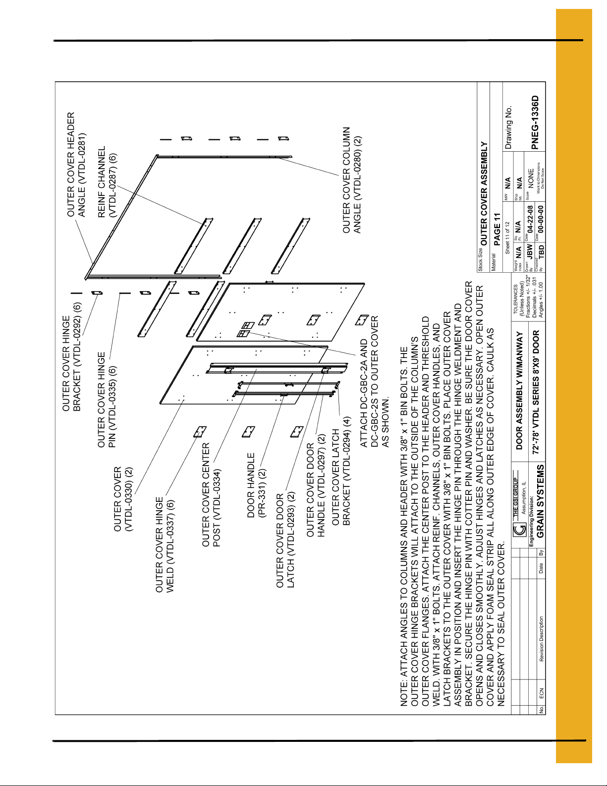
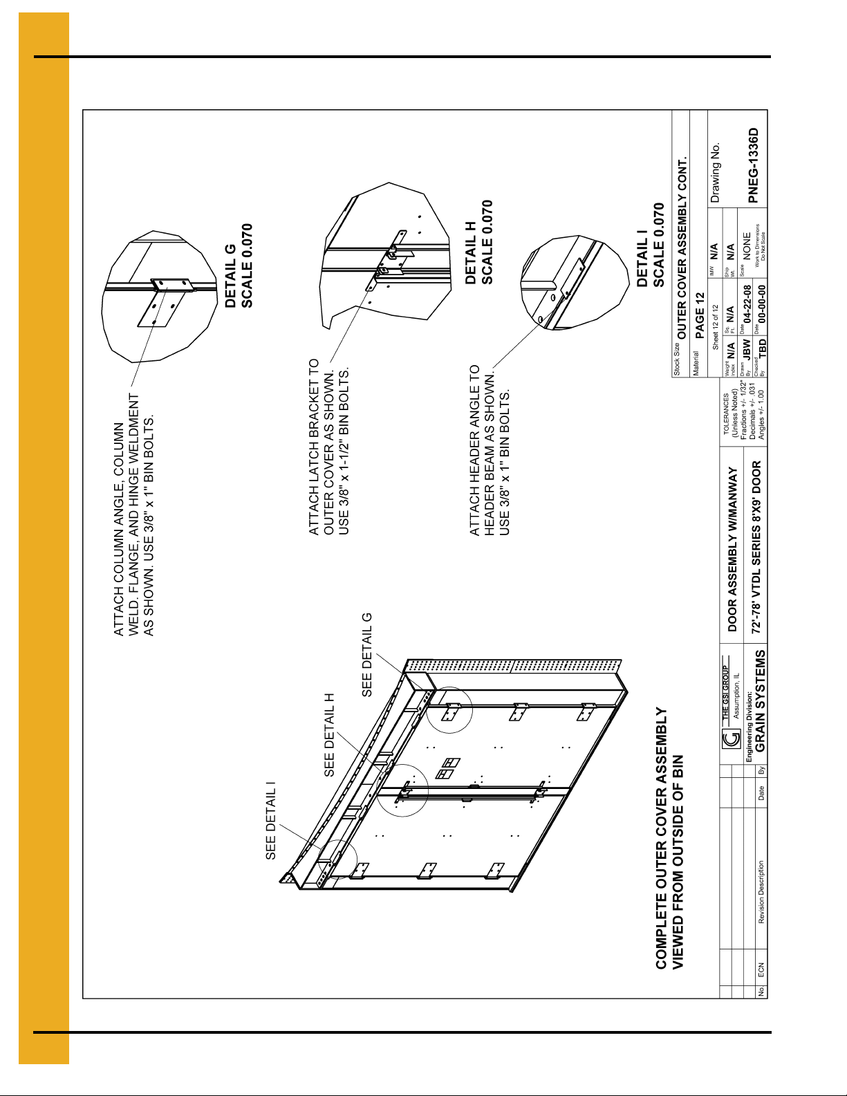
15. Assemble outer cover as shown on Page 27. Apply strip of caulk behind column and header angles
before attaching them to column and header beam clips. Attach center post and center door latch
(VTDL-0293) to header angle and threshold weldment. Apply caulking to the top and bottom of
center post. Assemble door outer cover, reinforcement channels, hinges, latch brackets and door
handles as shown on Page 27. 3/8" x 1" Bin bolts will be used for all connections. Use 3/8" nut and
sealing washer as spacer between latch bracket and outer cover. Place outer cover in doorframe
and align hinge weldment (VTDL-0337) with hinge bracket (VTDL-0292). Insert hinge pins
(VTDL-0335) through hinges and hold in place with washers and cotter pins. Review details
G-I on Page 28 for connection details. Adjust door hinges and latches as necessary until door
opens and closes smoothly. Apply foam seal strip around perimeter of outer cover and caulk as
necessary to seal outer cover. Place decals DC-GBC-2A and DC-GBC-2S on the outer cover as
shown on Page 28.
16. To open door, open outer cover and remove door cover or tie back to bin, remove center post,
unbolt door panels from doorframe. Do not remove hinges or unbolt door panels from one another.
Swing door panels open to remove center column. Provisions should be made to hold the door
panels open while center column is being removed and bin is being cleaned. Unbolt top of center
column from header beam and remove shim plate. Slide center column section inside off the
threshold weldment, tilt outward and remove. Caution center column is extremely heavy and proper
equipment should be used for removal. Temporary ramps should be made to avoid driving over the
door panel attachment plates of the threshold weldment. Once the bin is fully emptied, re-install the
center column section, close door panels, and bolt panels to doorframe. It may be necessary to
re-seal around door panels and column weldments. Close outer cover and re-seal as necessary.
Inspect all decals each time door is opened and replace if damaged or missing.
Recommended Tools for Installing VTDL-72-8X9 Door
1. Forklift or similar piece of equipment capable of lifting 1500 lbs. at heights above 10'.
2. Welder
3. Plasma cutter, torch, or similar tool for cutting base plates.
4. Concrete drill for installing 3/4" epoxy type anchors (if anchors are used).
5. 1/2" and 7/16" drill bits.
6. Sockets and wrenches including 9/16", 5/8", 1-1/8", and 1-1/2" sizes.
7. Drift pins and/or pry bars.
16 PNEG-1336D VTDL-72-8X9D - VTDL-78-8X9D Door
Page 17

Sidewall and Stiffener Layout
5. Door Assembly
PNEG-1336D VTDL-72-8X9D - VTDL-78-8X9D Door 17
Page 18

5. Door Assembly
Door Assembly Exploded View
MANWAY DOOR PANEL
ASSEMBLY REFER
PAGES 23-24
SEE PAGE
DOOR PA NEL ASSEMBLY
REFER P AGES 23-24
OUTER COVER
ASSEMBLY
REFER PAGE 27
18 PNEG-1336D VTDL-7 2-8X9D - VTDL-78-8X9D Door
Page 19
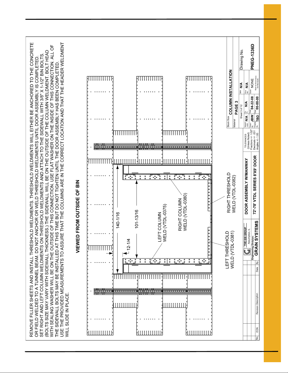
Column Installation
5. Door Assembly
PNEG-1336D VTDL-72-8X9D - VTDL-78-8X9D Door 19
Page 20
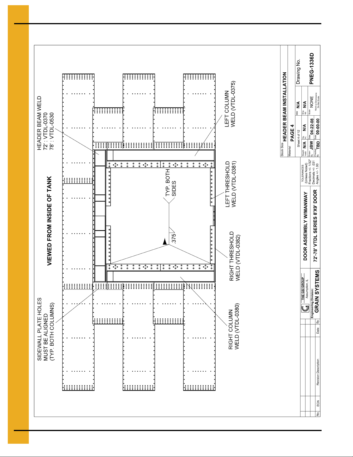
5. Door Assembly
Header Beam Installation
THE HEADER BEAM MUST SLIDE ONTO THE COLUMNS FROM THE INSIDE OF THE TANK. THE SEAL
STRIP ATOP OF THE HEADER WILL BOLT TO THE FIFTH RING FROM THE INSIDE OF THE TANK.
ATTACH THE HEADER TO THE COLUMNS WITH 1" x 3-1/2" GRADE 8 BOLTS, NUTS AND WASHERS.
20 PNEG-1336D VTDL-7 2-8X9D - VTDL-78-8X9D Door
REFER PAGE 21 FOR HEADER TO COLUMN CONNECTION DETAILS. REQUIRED FIELD WELDING
DOOR A TTACHMENT PLATES AS SHOWN. REFE R PAGE 26 FOR COMPLETE WELD DETAILS. (VIEWED
FROM INSIDE OF TANK).
SHOULD BE DONE AFTER DOOR IS COMPLETELY INSTALLED. FIELD WELD SIDEWALL PLATES AND
Page 21

Header Beam Connection Details
5. Door Assembly
NOTE: INSTALL HEADER BEAM ONTO COLUMNS AS SHOWN ON PAGE 20. USE 1" x 3-1/2"
GRADE 8 BOL TS WITH WASHER ON EACH SIDE. INSER T BOL T FROM THE COLUMN SIDE AND
TIGHTEN. ACCESS COVER PLATES (VTDL-0246) WILL BE WELDED ONTO THE INSIDE AND
OUTSIDE OF THE COLUMNS A T THE ACCESS OPENING AFTER THE DOOR IS INSTALLED. BE
SURE THAT THE EDGE OF THE THRESHOLD PLATE IS ALIGNED WITH THE EDGE OF THE
COLUMNS. FIELD WELD THRESHOLD PLATES, SIDEWALL PLATES, AND DOOR PANEL
PLATES AFTER DOOR IS COMPLETELY INSTALLED.
PNEG-1336D VTDL-72-8X9D - VTDL-78-8X9D Door 21
Page 22

5. Door Assembly
Center Column Installation
22 PNEG-1336D VTDL-7 2-8X9D - VTDL-78-8X9D Door
Page 23

Door Panel Assembly
5. Door Assembly
DOOR PANELS SHOULD BE ASSEMBLED AS SHOWN. ATTACH THE DOOR PANELS
TO THE COLUMNS, HEADER, AND THRESHOLD WITH 1" x 2-1/2" GRADE 8 BOLTS
WITH WASHERS ON EACH SIDE. BOLT HEAD SHOULD BE ON THE OUTSIDE OF
THE CONNECTION. USE 1" x 3-1/2" GRADE 8 BOLTS AT HINGE LOCATIONS. USE
FOAM SEAL STRIP ON BACK SIDE OF DOOR PANELS. APPLY CAULKING BETWEEN
ALL DOOR PANEL SPLICES. ATTACH HINGE WELDMENTS TO DOOR PANELS WITH
3/8" x 1-1/2" BIN BOLTS. BOLT HEAD WITH SEALING WASHER SHOULD BE ON
THE INSIDE FOR THESE CONNECTIONS. REFER PAGE 24 FOR DOOR PANEL TO
FRAME ASSEMBLY.
PNEG-1336D VTDL-72-8X9D - VTDL-78-8X9D Door 23
Page 24

5. Door Assembly
Door Panel Assembly (2)
24 PNEG-1336D VTDL-7 2-8X9D - VTDL-78-8X9D Door
Page 25

Stiffener/SDW Attachment
5. Door Assembly
PNEG-1336D VTDL-72-8X9D - VTDL-78-8X9D Door 25
Page 26

5. Door Assembly
Weld Details
26 PNEG-1336D VTDL-7 2-8X9D - VTDL-78-8X9D Door
Page 27
Outer Cover Assembly
5. Door Assembly
PNEG-1336D VTDL-72-8X9D - VTDL-78-8X9D Door 27
Page 28
5. Door Assembly
Outer Cover Assembly (Continued)
28 PNEG-1336D VTDL-7 2-8X9D - VTDL-78-8X9D Door
Page 29

5. Door Assembly
VTDL Door Foundation Note
VTDL doors will require special foundation requirements and aeration floor systems. The following
pages (Pages 30, 31 and 32) contain foundation sp ecifica tions fo r the in stallation o f VTDL doors in 72 '
through 78' diameter externally stiffened tanks. These specifications are based on the Grain Systems
Concrete Manual PNEG-318. All foundation specifications shall be construed as recommendations only.
Because of the many variable conditions in actual installation, Grain Systems assumes no liability for
results arising from the use of such recommendations. Please contact the Grain Bin Engineering
Department if there are any specific questions about the concrete requirements for a VTDL door.
PNEG-1336D VTDL-72-8X9D - VTDL-78-8X9D Door 29
Page 30

5. Door Assembly
R417-3/4 STD INNER
WALL RADIUS
30 PNEG-1336D VTDL-7 2-8X9D - VTDL-78-8X9D Door
Page 31

5. Door Assembly
3'-0"
PNEG-1336D VTDL-72-8X9D - VTDL-78-8X9D Door 31
Page 32

5. Door Assembly
R40' 7" OUTER WALL RADIUS
32 PNEG-1336D VTDL-7 2-8X9D - VTDL-78-8X9D Door
Page 33

6. Warranty
The GSI Group Limited Warranty
The GSI Group, Inc. (“GSI”) warrants products which it manufactures to be free of defects in materials
and workmanship under normal usage and conditions for a period of 12 months after sale to the orig inal
end-user or if a foreign sale, 14 months from arrival at port of discharge, whichever is earlier. The
end-user’s sole remedy (and GSI’s only obligation) is to repair or replace, at GSI’s option and expense,
products that in GSI’s judgment, contain a material defect in materials or workmanship. Expenses
incurred by or on behalf of the end-user without prior written authorization from the GSI Warranty Group
shall be the sole responsibility of the end-user.
Warranty Extensions:
The Limited Warranty period is extended for the following products:
Product Warranty Period
AP Fans and Flooring
Cumberland
Feeding/Watering
Systems
Grain Systems
Performer Series Direct Drive Fan Motor 3 Years
All Fiberglass Housings Lifetime
All Fiberglass Propellers Lifetime
Apex Flooring 10 Years *
Feeder System Pan Assemblies 5 Years **
Feed Tubes (1.75" and 2.00") 10 Years *
Centerless Augers 10 Years *
Watering Nipples 10 Years *
Grain Bin Structural Design 5 Years
Portable Dryers (Excluding Motors) 2 Years
* Warranty prorated from list price:
0 to 3 years - no cost to end-user
3 to 5 years - end-user pays 25%
5 to 7 years - end-user pays 50%
7 to 10 years - end-user pays 75%
** Warranty prorated from list price:
0 to 3 years - no cost to end-user
3 to 5 years - end-user pays 50%
Conditions and Limitations:
THERE ARE NO WARRANTIES THAT EXTEND BEYOND THE LIMITED WARRANTY DESCRIPTION
SET FORTH ABOVE. SPECIFICALLY, GSI MAKES NO FURTHER WARRANTY OF ANY KIND,
EXPRESS OR IMPLIED, INCLUDING, WITHOUT LIMITATION, WARRANTIES OF
MERCHANTABILITY OR FITNESS FOR A PARTICULAR PURPOSE OR USE IN CONNECTION
WITH: (I) PRODUCT MANUFACTURED OR SOLD BY GSI OR (II) ANY ADVICE, INSTRUCTION,
RECOMMENDATION OR SUGGESTION PROVIDED BY AN AGENT, REPRESENTATIVE OR
EMPLOYEE OF GSI REGARDING OR RELATED TO THE CONFIGURATION, INSTALLATION,
LAYOUT, SUITABILITY FOR A PARTICULAR PURPOSE, OR DESIGN OF SUCH PRODUCTS.
GSI shall not be liable for any direct, indirect, incidental or consequential damages, including, without
limitation, loss of anticipated profits or benefits. The sole and exclusive remedy is set forth in the Limited
Warranty, which shall not exceed the amount paid for the product purchased. This warranty is not
transferable and applies only to the original end-user. GSI shall have no obligation or responsibility for
any representations or warranties made by or on behalf of any dealer, agent or distributor.
GSI assumes no responsibility for claims resulting from construction defects or unauthorized
modifications to products which it manufactured. Modifications to products not specifically delineated in
the manual accompanying the equipment at initial sale will void the Limited Warranty.
This Limited Warranty shall not extend to products or parts which have been damaged by negligent use,
misuse, alteration, accident or which have been improperly/inadequately maintained. This Limited
Warranty extends solely to products manufactured by GSI.
Prior to installation, the end-user has the responsibility to comply with federal, state and local codes
which apply to the location and installation of products manufactured or sold by GSI.
9101239_1_CR_rev3.DOC (rev ised February 2008)
PNEG-1336D VTDL-72-8X9D - VTDL-78-8X9D Door 33
Page 34
This equipment shall be installed in accordance with
the current installation codes and applicable
regulations which should be carefully followed in all
cases. Authorities having jurisdiction should be
consulted before installations are made.
Copyright © 2008 by GSI Group
Printed in the USA
GSI Group
1004 E. Illinois St.
Assumption, IL 62510-0020
Phone: 1-217-226-4421
Fax: 1-217-226-4420
www.gsiag.com
 Loading...