


PNEG-1070
15', 18', 21', 24', 27' and 30'
Diameter Commercial
Hopper Tanks
Installation Manual
PNEG-1070
Version: 2.0
Date: 11-29-11

All information, illustrations, photos and specifications in this manual are based on the latest
information available at the time of publication. The right is reserve d to make changes at any time
without notice.
2 PNEG-1070 15', 18', 21', 24', 27' and 30' CHT’s

Table of Contents
Contents
Chapter 1 Introduction ..........................................................................................................................................5
Chapter 2 Safety .....................................................................................................................................................6
Safety Guidelines .................................................................................................................................. 6
General Safety Statement ..................................................................................................................... 7
Safety Instructions ..................... ... .... .......................................... ... ... ..................................................... 8
Safety Sign-Off Sheet ......................................................................................................................... 10
Proper Storage of Grain Bin/Silo Materials Prior to Construction ....................................................... 11
Chapter 3 Decals ..................................................................................................................................................12
Chapter 4 Foundation ..........................................................................................................................................16
12' Diameter Commercial Hopper Tank Foundation up to 12 Rings ................................................... 16
12' Diameter Commercial Hopper Tank Foundation for 13-17 Rings ................................................. 17
15' Diameter Commercial Hopper Tank Foundation up to 12 Rings ................................................... 18
15' Diameter Commercial Hopper Tank Foundation for 13-17 Rings ................................................. 19
18' Diameter Commercial Hopper Tank Foundation up to 12 Rings ................................................... 20
18' Diameter Commercial Hopper Tank Foundation for 13-19 Rings ................................................. 21
21' Diameter Commercial Hopper Tank Foundation up to 12 Rings ................................................... 22
21' Diameter Commercial Hopper Tank Foundation for 13-19 Rings ................................................. 23
24' Diameter Commercial Hopper Tank Foundation up to 12 Rings ................................................... 24
24' Diameter Commercial Hopper Tank Foundation for 13-19 Rings ................................................. 25
27' Diameter Commercial Hopper Tank Foundation up to 12 Rings ................................................... 26
27' Diameter Commercial Hopper Tank Foundation for 13-19 Rings ................................................. 27
30' Diameter Commercial Hopper Tank Foundation up to 12 Rings ................................................... 28
30' Diameter Commercial Hopper Tank Foundation for 13-19 Rings ................................................. 29
CHT Column Heights ... ... .... ... ... ... .... ... ... .......................................... ... ... ............................................. 30
Substructure Parts .............................................. ... ... .... ... ... ... .......................................... ................... 31
Typical NCHT Column ........................................................................................................................ 32
Chapter 5 15'-24' Hopper Assembly ...................................................................................................................33
Hopper Section Assembly 15'-24' (4.57 m-7.32 m) Diameter Hopper Tanks ..................................... 33
18'-21' (5.49 m-6.40 m) 60° “X” Bracing Detail ............................................. ...................................... 38
Chapter 6 27'-30' Hopper Assembly ...................................................................................................................39
Hopper Section Assembly 27'-30' (8.23 m-9.14 m) Diameter Hopper Tanks ..................................... 39
Chapter 7 Sidewall Assembly .............................................................................................................................43
Sidewall Erection Instructions ... ... .......................................... .... ... ... ... ... .... ... ... ... ................................ 43
Decal Sheet Placement ....................................................................................................................... 43
Chapter 8 Lifting Jack .........................................................................................................................................44
Lifting Jack Usage .................................. ... ... .... ... ... ... .......................................... .... ... ... ...................... 44
Color Code Chart ................................................................................................................................ 45
Chapter 9 Hardware .............................................................................................................................................46
Identifying Bolt Grades ........................... ... ... .... ... .......................................... ... ... .... ............................ 46
Hardware Identification Notes ....................................... .......................................... ............................ 47
2.66" Commercial Tank Bolting Requirements 2 Stiffeners per Sidewall Sheet ................................. 51
Caulking Detail .................................................................................................................................... 52
PNEG-1070 15', 18', 21', 24', 27' and 30' CHT’s 3

Table of Contents
Chapter 10 Stiffeners ...........................................................................................................................................53
Commercial Stiffeners for 2.66" Corrugation ..................................................................................... 54
2.66'' Corrugation Commercial Stiffener Splice Details ..................................................................... 55
10 Gauge and 11 Gauge Stiffener Bearing Splice ............................................................................ 57
5 Gauge, 6 Gauge, 8 Gauge and 9 Gauge Stiffener Bearing Splice ................................................. 58
Laminated Stiffener Splice 2.66" Corrugation .................................................................................... 59
Laminated to Universal Stiffener Splice 2.66" Corrugation ................................................................ 61
Stiffener to Sidewall Connections 3 Post Tanks ................................................................................ 62
Non-Laminated Stiffener to Sidewall Detail ....................................................................................... 63
Laminated Stiffener to Sidewall Detail ............................................................................................... 64
Universal Stiffener Starting Location 2.66" Reverse Corrugation Outside Stiffener Only .................. 65
Wind Ring Assembly ......................................................................................................................... 66
Stiffener Shim Plate Detail (Use when Necessary) ........................................................................... 67
Chapter 11 Flashing Instructions (Optional) .....................................................................................................68
Chapter 12 Doors .................................................................................................................................................70
Access Door Weldment Assembly Hardware Package (PLS-41985) ................................................ 70
Chapter 13 Aeration .............................................................................................................................................71
Aeration Package (Optional) ............................................................................................................. 71
Chapter 14 Ladders .............................................................................................................................................74
Ladder Support Detail ........................................................................................................................ 74
Chapter 15 Hoisting .............................................................................................................................................75
Hoist Instructions ............................................................................................................................... 75
Chapter 16 Warranty ............................................................................................................................................79
4 PNEG-1070 15', 18', 21', 24', 27' and 30' CHT’s

1. Introduction
READ THIS MANUAL carefully to learn how to properly use and install equipment. Failure to do so could
result in personal injury or equipment damage.
INSPECT the shipment immediately upon arrival. The customer is responsible for ensuring that all
quantities are correct. The customer should report and note any damage or shortage on the bill of
lading to justify their claim to the transport company.
THIS MANUAL SHOULD BE CONSIDERED a permanent part of your equipment and should be easily
accessible when needed.
This warranty provides you the assurance that the company will back its products when defects appear
within the warranty period. In some circumstances, the company also provides field improvements, often
without charge to the customer, even if the product is out of warranty. Should the equipment be abused,
or modified to change its performance beyond the factory specifications, the warranty will become void
and field improvements may be denied.
PNEG-1070 15', 18', 21', 24', 27' and 30' CHT’s 5
2. Safety
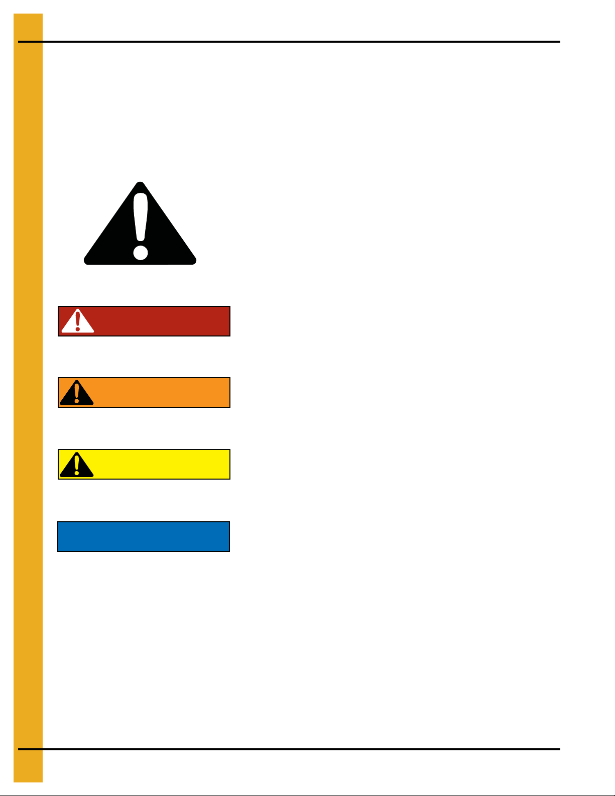
This is the safety alert symbol. It is used to alert you
to potential personal injury hazards. Obey all safety
messages that follow this symbol to avoid possible
injury or death.
WARNING indicates a hazardous situation which, if not
avoided, could result in death or serious injury.
CAUTION, used with the safety alert symbol, indicates a
hazardous situation which, if not avoided, could result in
minor or moderate injury.
NOTICE is used to address practices not related to
personal injury.
DANGER indicates a hazardous situation which, if not
avoided, will result in death or serious injury.
Safety Guidelines
This manual contains information that is important for you, the owner/operator, to know and understand.
This information relates to protecting personal safety and preventing equipment problems. It is the
responsibility of the owner/operator to inform anyone operating or working in the area of this equipment
of these safety guidelines. To help you recognize this information, we use the symbols that are defined
below. Please read the manual and pay attention to these sections. Failure to read this manual and its
safety instructions is a misuse of the equipment and may lead to serious injury or death.
DANGER
WARNING
CAUTION
NOTICE
6 PNEG-1070 15', 18', 21', 24', 27' and 30' CHT’s

2. Safety
This product has sharp edges, which may cause serious injury. T o avoid injury, handle sharp
edges with caution and always use proper protective clothing and equipment.
General Safety Statement
Our foremost concern is your safety and the safety of others associated with grain handling equipment.
This manual is to help you understand safe operating procedures and some problems that may be
encountered by the operator and other personnel.
As owner and/or operator, you are responsible to know what requirements, hazard s, and precautions exist
and inform all personnel associated with the equipment or in the area. Safety precautions may be required
from the personnel. Avoid any alterations to the equipment, which may produce a very dangerous
situation, where SERIOUS INJURY or DEATH may occur.
You should consider the location of the bin site relative to power line locations or electrical transmission
equipment. Contact your local power company to review your installation plan or for information
concerning required equipment clearance. Clearance of portable equipment that may be taken to the bin
site should also be reviewed and considered. Any electrical control equipment in contact with the bin
should be properly grounded and installed in accordance with National Electric Code provisions and other
local or national codes.
This product is intended for the use of grain storage only. Any other use is a misuse of the product.
Sidewall bundles or sheets must be stored in a safe manner. The safest method of storing sidewall
bundles is laying horizontally with the arch of the sheet upward, like a dome. Sidewall sheets stored on
edge must be secured so that they cannot fall over and cause injury. Use care when handling and moving
sidewall bundles.
Personnel operating or working around equipment should read this manual. This manual must be
delivered with equipment to its owner. Failure to read this manual and its safety instructions is a misuse
of the equipment.
PNEG-1070 15', 18', 21', 24', 27' and 30' CHT’s 7

2. Safety
Follow Safety Instructions
Carefully read all safety messages in this manual and
safety signs on your machine. Keep signs in good
condition. Replace missing or damaged safety signs. Be
sure new equipment components and repair parts include
the current safety signs. Replacement safety signs are
available from the manufacturer.
Learn how to operate the machine and how to use controls
properly. Do not let anyone operate without instruction.
Keep your machinery in proper working condition.
Unauthorized modifications to the machine may impair
the function and/or safety and affect machine life.
If you do not understand any part of this manual or need
assistance, contact your dealer.
Read and Understand Manual
Practice Safe Maintenance
Understand service procedures before doing work. Keep area
clean and dry.
Never lubricate, service, or adjust machine while it is in operation.
Keep hands, feet, and clothing away from rotating parts.
Keep all parts in good condition and properly installed. Fix
damage immediately . Replace worn or broken p arts. Remove any
built-up grease, oil, and debris.
Maintain Equipment
and Work Area
Safety Instructions
Our foremost concern is your safety and the safety of others associated with this equipment. We want to
keep you as a customer. This manual is to help you understand safe operating procedures and some
problems that may be encountered by the operator and other personnel.
As owner and/or operator, it is your responsibility to know what requirements, hazards, and precautions
exist, and to inform all personnel associated with the equipment or in the area. Safety precautions may be
required from the personnel. Avoid any alterations to the equipment. Such alterations may p roduce a very
dangerous situation where SERIOUS INJURY or DEATH may occur.
This equipment shall be installed in accordance with the current installation codes and applicable
regulations, which should be carefully followed in all cases. Authorities having jurisdiction should be
consulted before installations are made.
8 PNEG-1070 15', 18', 21', 24', 27' and 30' CHT’s
2. Safety
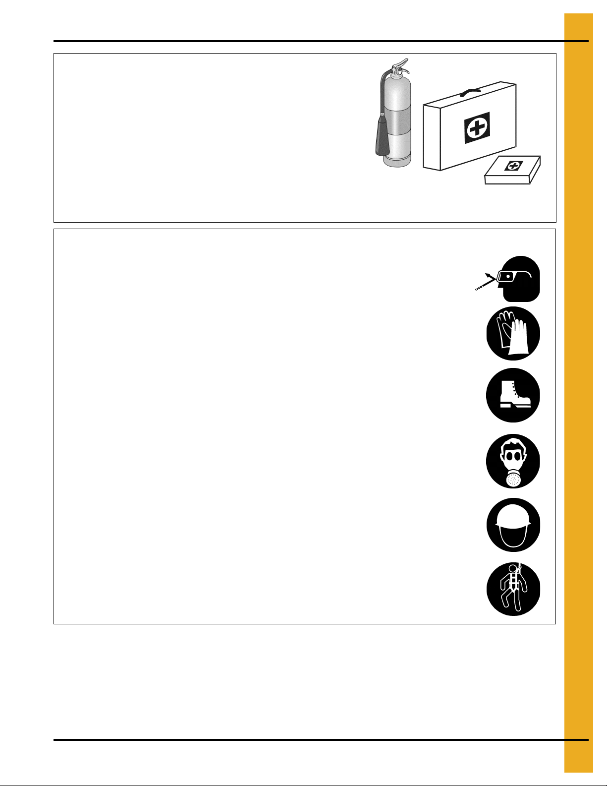
Prepare for Emergencies
Be prepared if fire starts.
Keep a first aid kit and fire extinguisher handy.
Keep emergency numbers for doctors, ambulance service,
hospital, and fire department near your telephone.
Keep Emergency Equipment
Quickly Accessible
Wear Protective Clothing
Wear close-fitting clothing and safety equipment appropriate
to the job.
Remove all jewelry.
Tie long hair up and back.
Wear safety glasses at all times to protect eyes from debris.
Wear gloves to protect your hands from sharp edges on plastic
or steel parts.
Wear steel-toed boots to help protect your feet from falling
debris. Tuck in any loose or dangling shoestrings.
A respirator may be needed to prevent breathing potentially
toxic fumes and dust.
Wear a hard hat to help protect your head.
Wear appropriate fall protection equipment when working at
elevations greater than six feet (6').
Eye Protection
Gloves
Steel-Toed Boots
Respirator
Hard Hat
Fall Protection
PNEG-1070 15', 18', 21', 24', 27' and 30' CHT’s 9

2. Safety
Safety Sign-Off Sheet
As a requirement of O.S.H.A., it is necessary for the employer to train the employee in the safe operating and
safety procedures for this auger. This sign-off sheet is provided for your convenience and personal record
keeping. All unqualified persons are to stay out of the work area at all times. It is strongly recommended that
another qualified person who knows the shut down procedure be in the area in the event of an emergency.
Date Employee Name Supervisor Name
10 PNEG-1070 15', 18', 21', 24', 27' and 30' CHT’s

2. Safety
Proper Storage of Grain Bin/Silo Materials Prior to Construction
Wet storage stain (rust) will develop when closely packed bundles of galvanized material, such as sidewall
and roof sheets, have moisture present. Inspect roof and sidewall bundles on arrival for any moisture. If
moisture is present, it must not be allowed to remain between the sheets. Separate the sheets or panels
immediately and wipe them down. Spray with a light oil or diesel fuel.
If possible, sidewall bundles, roof sheets and other closely packed galvanized materials should be stored
in a dry, climate controlled building. If outdoor storage is unavoidable, the materials should be stored so
that they are raised above the ground and vegetation. Any stacking and spacing materials should not be
corrosive or wet. Be sure to protect materials from the weather, but permit air movement around the
bundles if possible.
Storing roof bundles and sidewall sheets at a slight incline can also help minimize the presence of
moisture. Storing the bundles with the center of the dome up (like an arch) is one option for minimizing
moisture during storage. Sidewall bundles can also be stored on edge but must be secured so that they
do not fall over and cause injury.
If “white rust” or “wet storage stain” occurs, contact the manufacturer immediately about ways to minimize
the adverse effect upon the galvanized coating.
PNEG-1070 15', 18', 21', 24', 27' and 30' CHT’s 11
3. Decals
The manufacturer does not warrant any roof damage caused by excessive vacuum or internal
pressure from fans or other air moving systems. Adequate ventilation and/or “makeup air” devices
should be provided for all powered air handling systems. The manufacturer does not reco mmend
the use of downward flow systems (suction). Severe roof damage can result from any block age of
air passages. Running fans during high humidity/cold weather conditions can cause air exhaust
or intake ports to freeze.
CAUTION!
Excessive vacuum (or pressure) may
damage roof. Use positive aeration
system. Make sure all roof vents are
open and unobstructed. Start roof
fans when supply fans are started.
Do not operate when conditions exist
that may cause roof vent icing.
DC-969
12 PNEG-1070 15', 18', 21', 24', 27' and 30' CHT’s
3. Decals
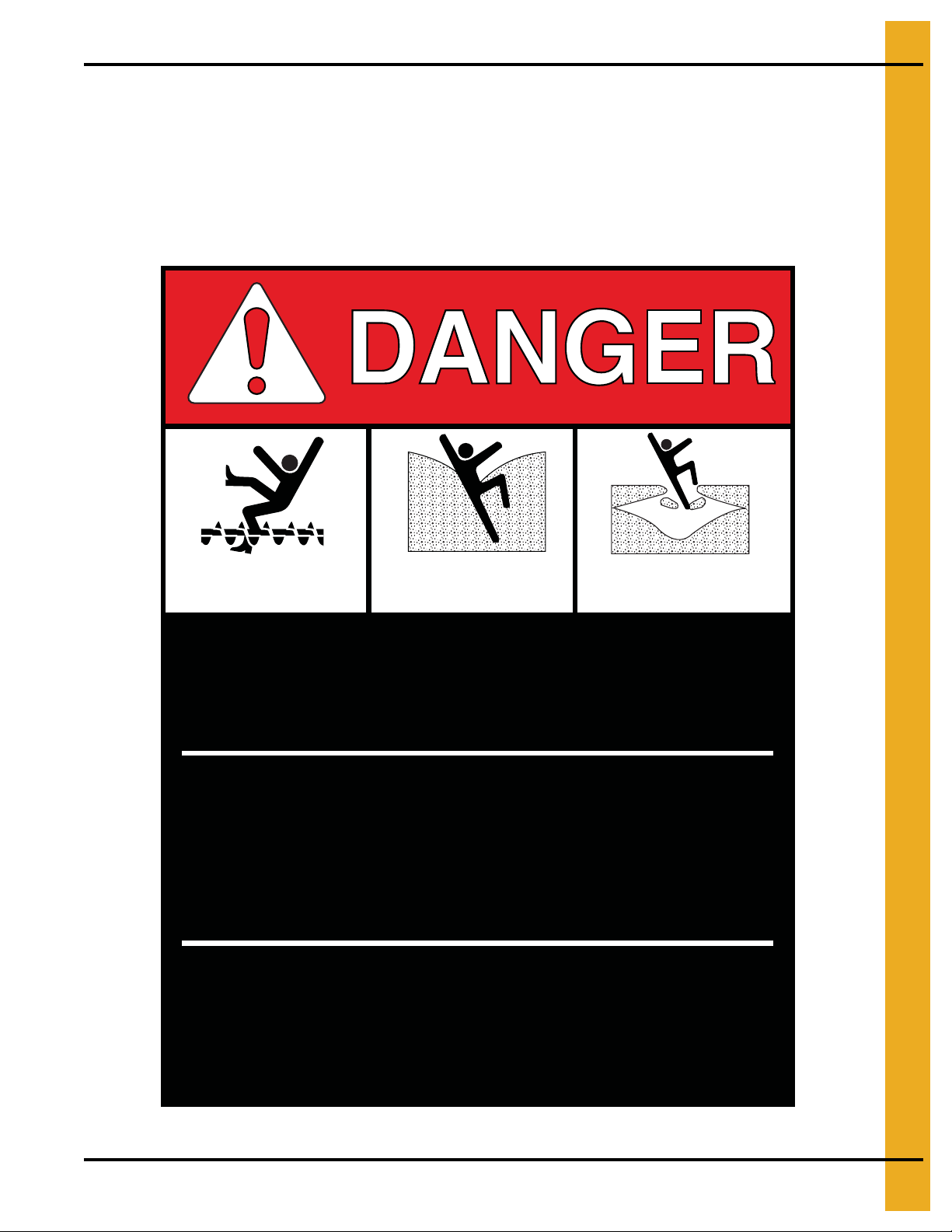
ATTENTION: The decal shown below should be present on the outside of the door cover of the 2 ring,
24" porthole door cover and roof manway cover. If a decal has been damaged or is missing in any of these
locations, contact the manufacturer for a free replacement decal.
GSI Decals
1004 E. Illinois St.
Assumption, IL. 62510
Phone: 1-217-226-4421
Rotating flighting will
kill or dismember.
Flowing material will
trap and suffocate.
Crusted material will
collapse and suffocate.
Keep clear of all augers.
DO NOT ENTER this bin!
If you must enter the bin:
1. Shut off and lock out all power.
2. Use a safety harness and safety line.
3. Station another person outside the bin.
4. Avoid the center of the bin.
5. Wear proper breathing equipment or respirator.
Failure to heed these
warnings will result in
serious injury or death.
DC-GBC-1A
PNEG-1070 15', 18', 21', 24', 27' and 30' CHT’s 13
3. Decals
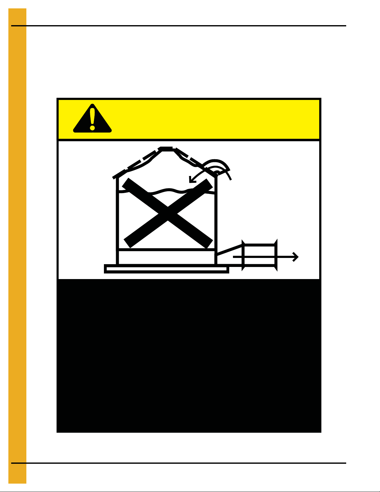
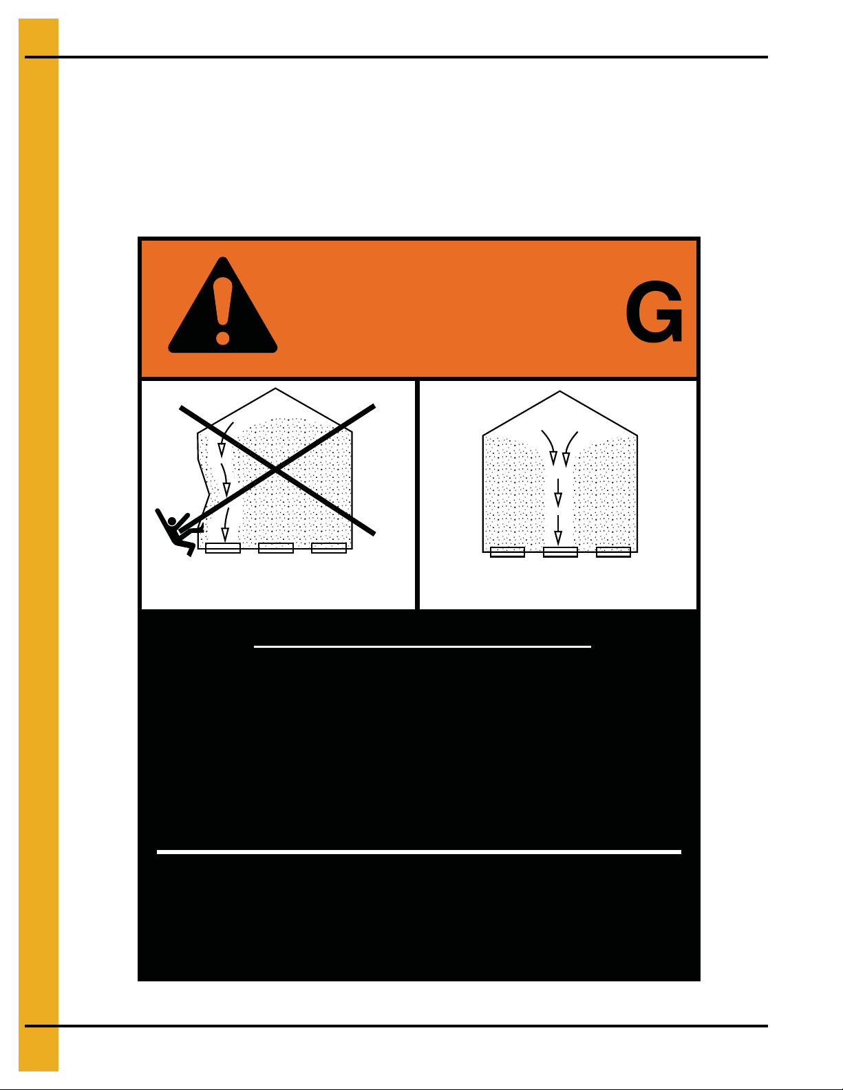
Failure to heed these warnings
could result in serious injury, death,
structural damage or collapse of tank.
1. Use CENTER FLOOR OUTLET ONLY until NO grain
remains above this outlet.
2. Side floor outlets to be used ONLY when above
condition is satisfied.
3. Lock all side floor outlets to avoid accidental
premature use.
4. See manufacturers instructions for proper use of
factory supplied sidedraw (wall) discharge systems.
UNLOADING INSTRUCTIONS:
DC-GBC-2A
WARNIN
DON’T
DO
ATTENTION: The decal shown below should be present on the outside of the door cover of the 2 ring,
24" porthole door cover and roof manway cover. If a decal has been damaged or is missing in any of these
locations, contact the manufacturer for a free replacement decal.
GSI Decals
1004 E. Illinois St.
Assumption, IL. 62510
Phone: 1-217-226-4421
14 PNEG-1070 15', 18', 21', 24', 27' and 30' CHT’s

Sidewall and stiffener gauge sheets
are not included in this manual.
They may be obtained by calling
GSI if they are not attached to the
front of this manual.
®
PNEG-1070 15', 18', 21', 24', 27' and 30' CHT’s 15
4. Foundation
12' Diameter Commercial Hopper Tank Foundation up to 12 Rings
Figure 4A
16 PNEG-1070 15', 18', 21', 24', 27' and 30' CHT’s
4. Foundation
12' Diameter Commercial Hopper Tank Foundation for 13-17 Rings
Figure 4B
PNEG-1070 15', 18', 21', 24', 27' and 30' CHT’s 17
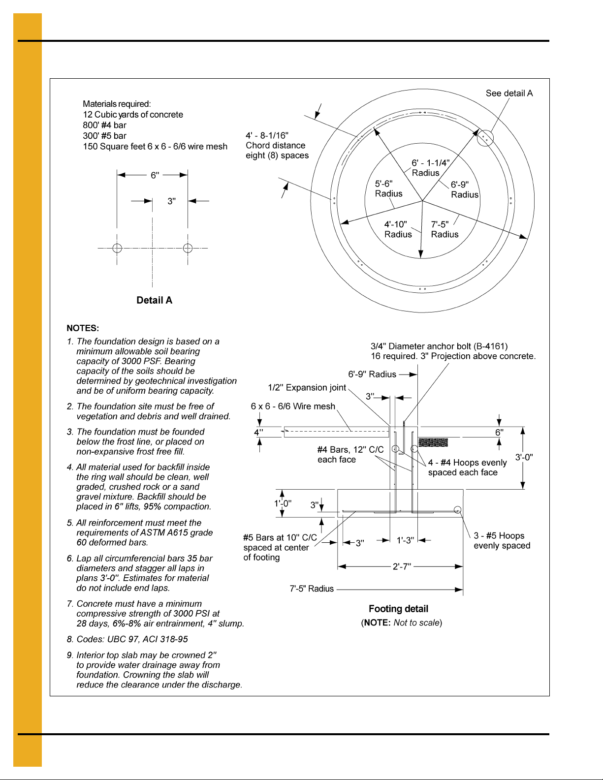
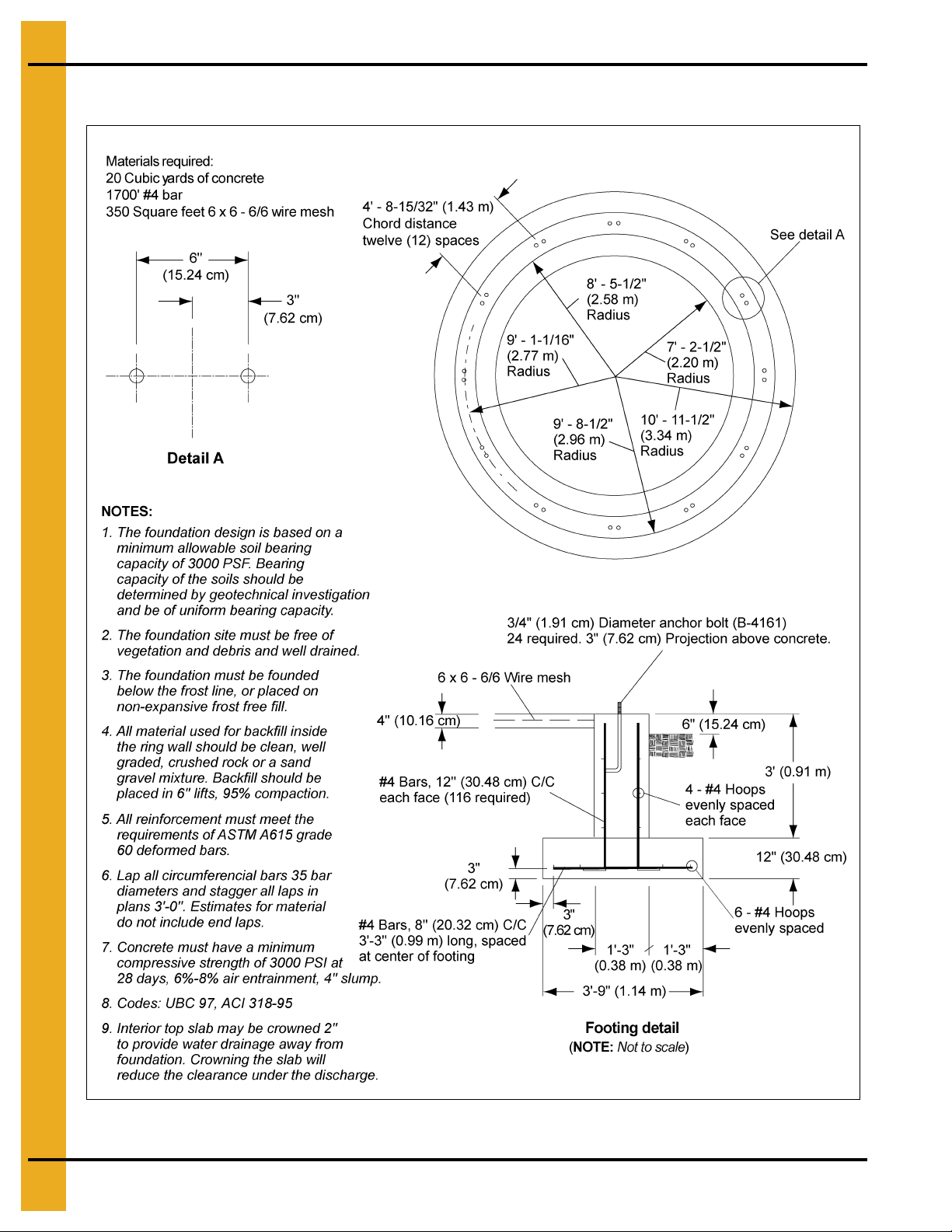
4. Foundation
15' Diameter Commercial Hopper Tank Foundation up to 12 Rings
Figure 4C
18 PNEG-1070 15', 18', 21', 24', 27' and 30' CHT’s

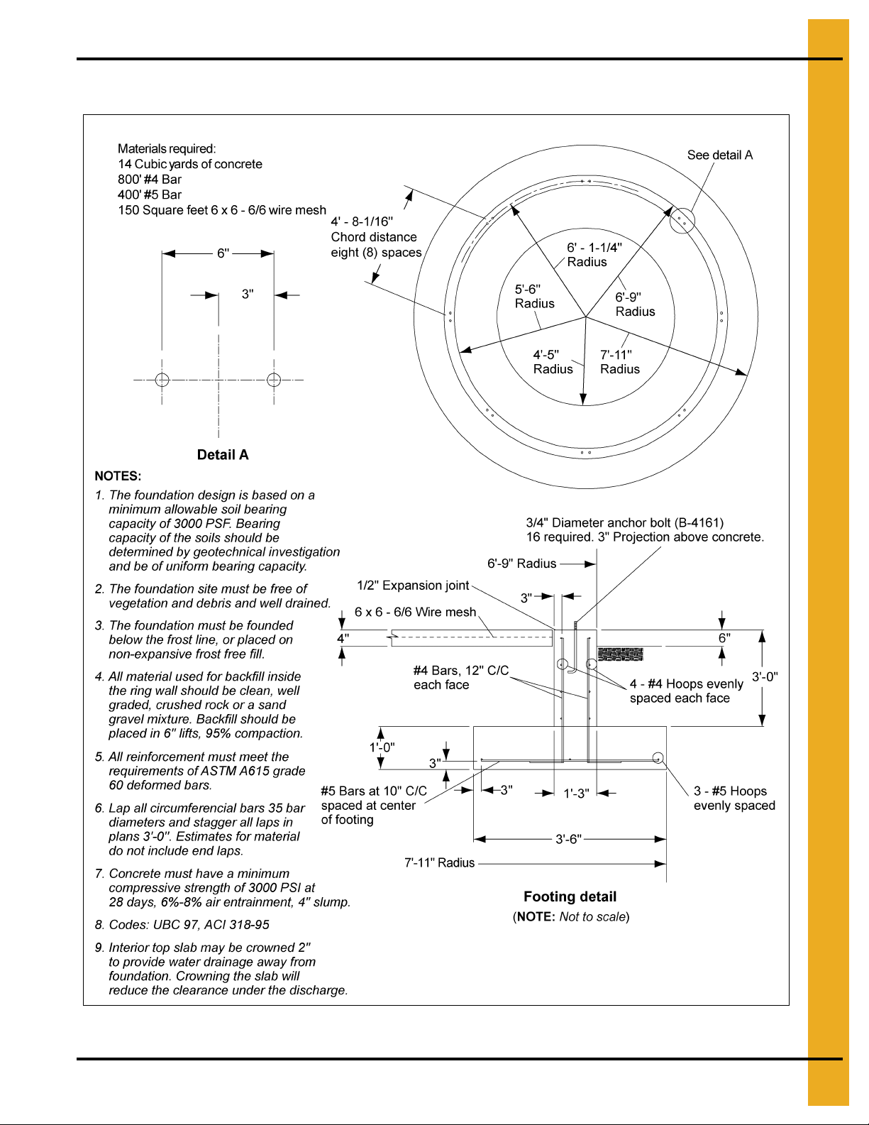
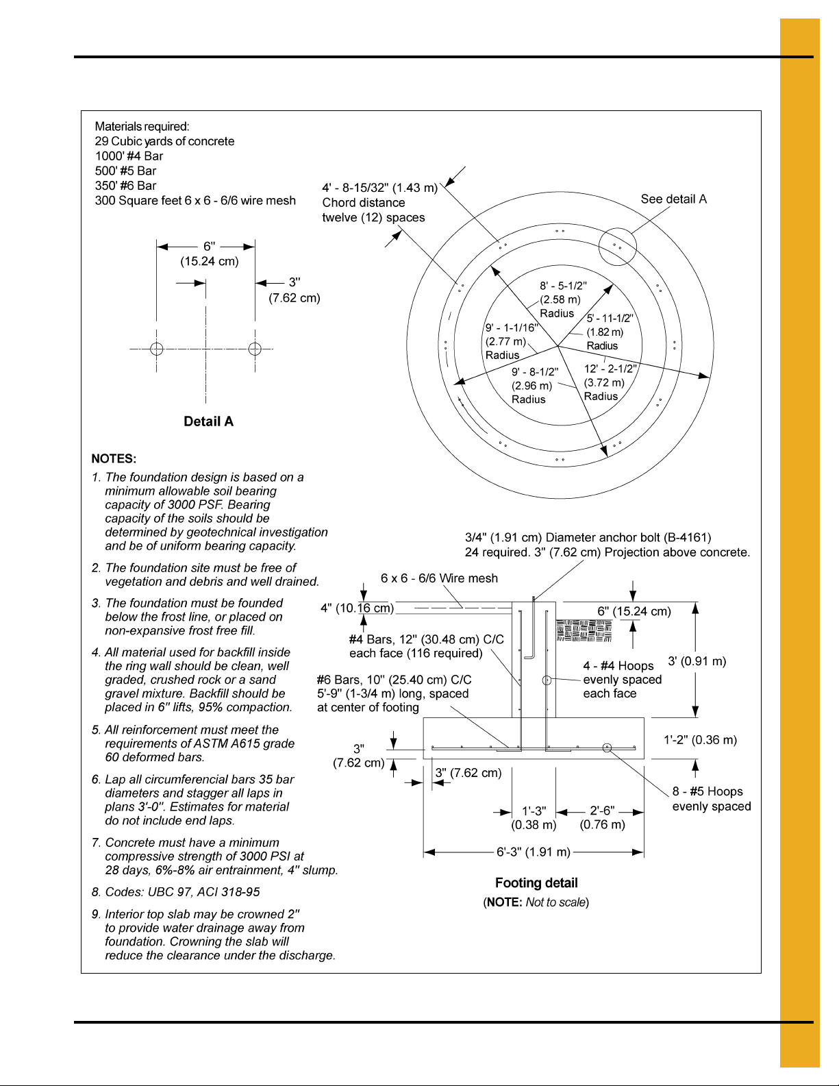
4. Foundation
15' Diameter Commercial Hopper Tank Foundation for 13-17 Rings
Figure 4D
PNEG-1070 15', 18', 21', 24', 27' and 30' CHT’s 19
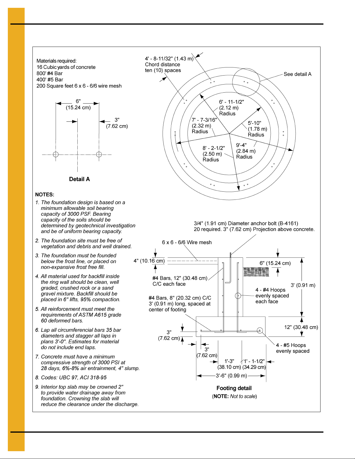
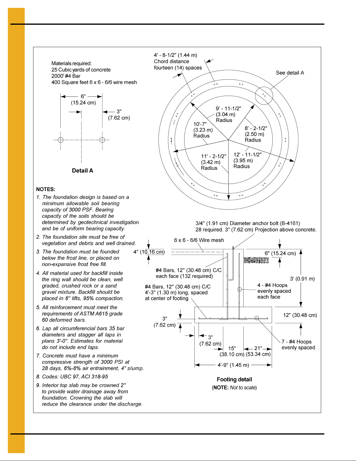
4. Foundation
18' Diameter Commercial Hopper Tank Foundation up to 12 Rings
Figure 4E
20 PNEG-1070 15', 18', 21', 24', 27' and 30' CHT’s
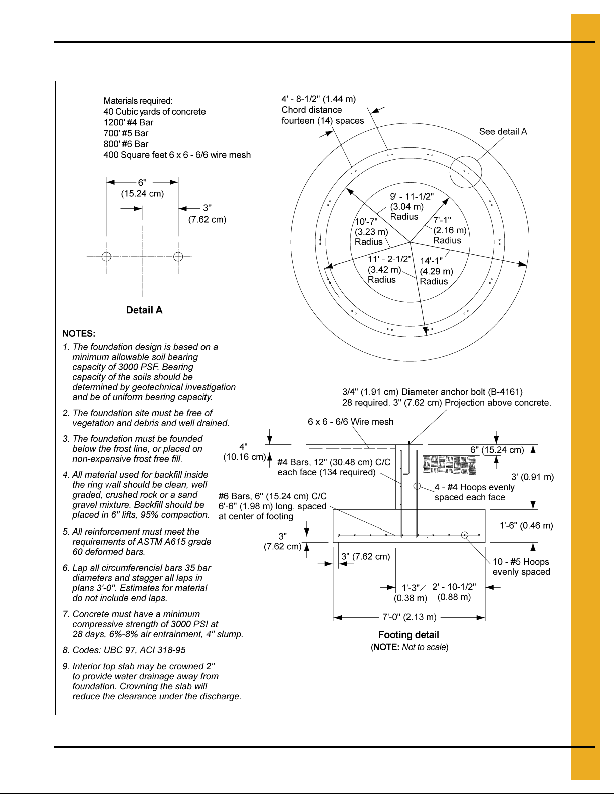
4. Foundation
18' Diameter Commercial Hopper Tank Foundation for 13-19 Rings
Figure 4F
PNEG-1070 15', 18', 21', 24', 27' and 30' CHT’s 21
4. Foundation
21' Diameter Commercial Hopper Tank Foundation up to 12 Rings
Figure 4G
22 PNEG-1070 15', 18', 21', 24', 27' and 30' CHT’s
4. Foundation
21' Diameter Commercial Hopper Tank Foundation for 13-19 Rings
Figure 4H
PNEG-1070 15', 18', 21', 24', 27' and 30' CHT’s 23

4. Foundation
24' Diameter Commercial Hopper Tank Foundation up to 12 Rings
Figure 4I
24 PNEG-1070 15', 18', 21', 24', 27' and 30' CHT’s

4. Foundation
24' Diameter Commercial Hopper Tank Foundation for 13-19 Rings
Figure 4J
PNEG-1070 15', 18', 21', 24', 27' and 30' CHT’s 25

4. Foundation
27' Diameter Commercial Hopper Tank Foundation up to 12 Rings
Figure 4K
26 PNEG-1070 15', 18', 21', 24', 27' and 30' CHT’s

4. Foundation
27' Diameter Commercial Hopper Tank Foundation for 13-19 Rings
Figure 4L
PNEG-1070 15', 18', 21', 24', 27' and 30' CHT’s 27

4. Foundation
30' Diameter Commercial Hopper Tank Foundation up to 12 Rings
Figure 4M
28 PNEG-1070 15', 18', 21', 24', 27' and 30' CHT’s

4. Foundation
30' Diameter Commercial Hopper Tank Foundation for 13-19 Rings
Figure 4N
PNEG-1070 15', 18', 21', 24', 27' and 30' CHT’s 29

4. Foundation
CHT Column Heights
Figure 4O Standard Commercial Hopper Tank Column Heights
Tank Diameter Hopper Slope
12' 45 7' - 11-7/8" 2.44 32 813
15' 45 9' - 5-3/8" 2.88 32 813
15' 60 14' - 4-5/8" 4.39 32 813
18' 45 11'-1/8" 3.36 32 813
18' 60 16' - 11-5/8" 5.17 32 813
21' 45 12'-5" 3.79 32 813
21' 60 19' - 6-3/4" 5.96 32 813
24' 45 13' - 10-7/8" 4.24 32 813
27' 40 12' - 2-7/8" 3.73 28 71 1
27' 45 15' - 4-3/8" 4.68 32 813
30' 40 13' - 4-7/8" 4.09 28 71 1
30' 45 16' - 10-1/4" 5.14 32 813
“A” Dimension “B” Dimension
Feet Meters Inches Millimeters
30 PNEG-1070 15', 18', 21', 24', 27' and 30' CHT’s

4. Foundation
Substructure Parts
Part List for Substructure for Commercial Hopper Tanks
Tank Size 15' - 45° 15' - 60° 18' - 45° 18' - 60°
Color Code Yellow Black and Y ellow Red Black and Red
Column Weldment CHT-1201 (10) SCHT-1444 (10) CHT-1184 (12) SCHT-1475 (12)
Compress Angle Weldment CHT-1202 (10) SCHT-1438 (10) CHT-1209 (12) SCHT-1986 (12)
Hopper Collar Weldment CHT-1135 (1) SCHT-1434 (1) CHT-1136 (1) SCHT-1466 (1)
“X” Bracing Rod CHT-1203 (20) SCHT-1432 (40) CHT-1175 (24) SCHT-1473 (48)
“X” Bracing Rod Size 3/4" x 100" 7/8" x 166" 3/4" x 116" 3/4" x 107"
Top R.H. Hopper Panel CHT-1390 (10) SCHT-1941 (10) CHT-1375 (12) SCHT-1987 (12)
Top L.H. Hopper Panel CHT-1391 (10) SCHT-1940 (10) CHT-1374 (12) SCHT-1988 (12 )
Bottom R.H. Hopper Panel N/A N/A N/A N/A
Bottom L.H. Hopper Panel N/A N/A N/A N/A
Compression Channel N/A N/A N/A N/A
Support Hardware CHT-1392 (1) SCHT-1949 (1) CHT-1373 (1) SCHT-1896 (1)
Tank Size 21' - 45° 21' - 60° 24' - 45° 27' - 40° 30' - 40°
Color Code Blue Black and Blue Green Orange Purple
Column Weldment CHT-1159 (14) SCHT-1484 (14) CHT-1118 (16) CHT-1017 (18) CHT-1037 (20)
Compress Angle Weldment CHT-1167 (14) SCHT-1471 (14) CHT-1119 (16) CHT-1018 (18) CHT-1038 (20)
Hopper Collar Weldment CHT-1137 (1) SCHT-1467 (1) CHT-1133 (1) CHT-1056 (1) CHT-1036 (1)
“X” Bracing Rod CHT-1144 (28) SCHT-1481 (56) CHT-1117 (32) CHT-1026 (36) CHT-1045 (40)
“X” Bracing Rod Size 3/4" x 126" 3/4" x 120" 3/4" x 144" 3/4" x 123" 3/4" x 137"
Top R.H. Hopper Panel CHT-1421 (14) SCHT-1463 (14) CHT-1372 (16) CHT-1479 (18) CHT-1366 (20)
Top L.H. Hopper Panel CHT-1420 (14) SCHT-1462 (14) CHT-1371 (16) CHT-1478 (18) CHT-1365 (20)
Bottom R.H. Hopper Panel N/A SCHT-1461 (14) N/A CHT-1481 (18) CHT-1368 (20)
Bottom L.H. Hopper Panel N/A SCHT-1460 (14) N/A CHT-1480 (18) CHT-1367 (20)
Compression Channel N/A N/A N/A CHT-1025 CHT-1052
Support Hardware** CHT-1422 (1) SCHT-1485 (1) CHT-1370 (1) CHT-1483 (1) CHT-1369 (1)
**NOTE: The 3/8" x 1" bin bolts (with sealing washer) for attachment hopper panels to the compression
element are included in the sidewall hardware.
PNEG-1070 15', 18', 21', 24', 27' and 30' CHT’s 31

4. Foundation
Typical NCHT Column
Figure 4P
32 PNEG-1070 15', 18', 21', 24', 27' and 30' CHT’s

5. 15'-24' Hopper Assembly
Hopper Section Assembly 15'-24' (4.57 m-7.32 m) Diameter
Hopper Tanks
Before placing the support columns on the anchor bolts, use a transit and surveyor’s rod to locate high
and low areas in the concrete. To assure level alignment for the support columns, use the proper supplied
shim or shims between the concrete and base plate. After leveling is completed, place the support
columns over the anchor bolts, with shim plates underneath column. Next place HT-635 washer over
anchor bolts and loosely fasten with nuts and washers (not furnished). Refer to Figure 5A.
NOTE: 15' (4.57 m) Diameter hopper tanks have 10 columns.
18' (5.49 m) Diameter hopper tanks have 12 columns.
21' (6.40 m) Diameter hopper tanks have 14 columns.
24' (7.32 m) Diameter hopper tanks have 16 columns.
Figure 5A
PNEG-1070 15', 18', 21', 24', 27' and 30' CHT’s 33

5. 15'-24' Hopper Assembly
Figure 5B Compression Angle Erection
Using 5/8"-11 x 1-1/2" bolts (S-4109) and 5/8" nuts (S-4110), fasten the compression angle segments to
the support clips on the support columns. A 5/8"-11 x 2-3/4" bolt (S-4108) and 5/8" nut (S-4110) may be
placed in the top hole of the support column for alignment purposes, but will be removed later when the
sidewall base stiffener is to be positioned. Refer to Figure 5C. Do not tighten bolts until hopper panels are
installed to allow alignment.
Figure 5C
34 PNEG-1070 15', 18', 21', 24', 27' and 30' CHT’s

5. 15'-24' Hopper Assembly
Detail B
Detail A
Begin assembling the hopper bottom by attaching a right and left pair or pairs of hopper panels to the
compression angle ring (3/8" x 1" bin bolt (S-455)) and discharge collar (1/2" x 1" hardware (S-4492)) at
four (4) opposing points as shown in Figure 5D. Caulking is required on the vertical seams of the lapped
hopper panels (Refer to Figure 5G). Splice plates which join the compression angle segments on the
back side may be installed following a pair of hopper panels. Refer to Figure 5F. Complete this assembly
by laying in alternate right and left panels moving around in one direction and lapping all sheets the
same way, See Figure 5E. Do not tighten bolts until all hopper panels are attached to each other, the
compression angle, splice plates and discharge collar.
On 15' through 24' tanks use 1/2" bolts on hopper seams.
NOTE: All bolts used in hopper assembly should be installed with the bolt heads to the inside of
the hopper.
Figure 5D Hopper Panel and Discharge
Collar Assembly
Figure 5E Lap Detail (Viewed from Inside of Bin)
Figure 5F Hopper Panel Detail
Figure 5G Caulking Detail
Figure 5H
Start at the bottom of the hopper and tighten all bolts, including anchor bolts, discharge collar, hopper
panels, splice plates and compression angle segments.
PNEG-1070 15', 18', 21', 24', 27' and 30' CHT’s 35

5. 15'-24' Hopper Assembly
If a rack and pinion gate is purchased, install as shown in Figure 5I using 5/16" x 3/4" hardware (S-275).
Figure 5I Hopper Discharge Collar to Roller Gate
36 PNEG-1070 15', 18', 21', 24', 27' and 30' CHT’s

5. 15'-24' Hopper Assembly
Install “X” bracing rods as in Figure 5J, Figure 5K and Figure 5L.
When the hopper structure has been completed, it should be level to within ± 1/8" ma ximum deviation, as
compared to all other support columns as measured at the top of the compression angle ring. The support
columns must be plumb to within ± 1/2" as measured from top to bottom. Seal any gaps between
compression elements and the seal strip at column locations with silicon or other conventional means.
Figure 5J Completed Hopper Assembly
Figure 5K “X” Bracing Rods
Figure 5L
PNEG-1070 15', 18', 21', 24', 27' and 30' CHT’s 37

5. 15'-24' Hopper Assembly
18'-21' (5.49 m-6.40 m) 60° “X” Bracing Detail
Install “X” bracing rods as in Figure 5M, Figure 5N and Figure 5O.
When the hopper structure has been completed, it should be level to within ± 1/8" ma ximum deviation, as
compared to all other support columns as measured at the top of the compression angle ring. The support
columns must be plumb to within ± 1/2" as measured from top to bottom. Seal any gaps between
compression elements and the seal strip at column locations with silicon or other conventional means.
Figure 5M Completed Hopper Assembly
Figure 5N “X” Bracing Rods
Figure 5O
38 PNEG-1070 15', 18', 21', 24', 27' and 30' CHT’s

6. 27'-30' Hopper Assembly
Hopper Section Assembly 27'-30' (8.23 m-9.14 m) Diameter
Hopper Tanks
Before placing the support columns on the anchor bolts, use a transit and surveyor’s rod to locate high
and low areas in the concrete. To assure level alignment for the support columns, use the proper supplied
shim or shims between the concrete and base plate. After leveling is completed, place the support
columns over the anchor bolts, with shim plates underneath column. Next place HT-635 washer over
anchor bolts and loosely fasten with nuts and washers (not furnished). Refer to Figure 6A. Seal any
gaps between compression elements and the seal strip at column locations with silicon or other
conventional means.
Figure 6A Column Shim Plate Detail (Use when Necessary)
PNEG-1070 15', 18', 21', 24', 27' and 30' CHT’s 39

6. 27'-30' Hopper Assembly
Detail G
Detail H
Use a transit and surveyor’s rod to locate high and low areas in the concrete, before placing the support
columns on the anchor bolts. To assure level alignment, use the proper sup plied shim o r sh ims b etween
the concrete and base plate. After leveling, place the support columns over the anchor bolts, on the shims
and loosely fasten with nuts and washers (not supplied). Refer to Figure 6A on Page 39.
NOTE: 27' (8.23 m) Diameter hopper tanks have 18 columns.
30' (9.14 m) Diameter hopper tanks have 20 columns.
Figure 6B Compression Angle Erection
Using 5/8"-11 x 2" hardware (S-4329), fasten the inside and outside vertical compression angle segments
and splice plates to the support columns, See Figure 6A on Page 39 and Detail G in Figure 6C. Next,
attach the horizontal channels with 5/8"-11 x 1-1/2" hardware (S-4109) to the inside and outside
vertical compression angle segments and the support clips on the support columns, as shown in Detail H
in Figure 6C. Do not tighten bolts until hopper panels are installed to allow alignment.
Figure 6C
40 PNEG-1070 15', 18', 21', 24', 27' and 30' CHT’s

6. 27'-30' Hopper Assembly
Detail J
Detail K
Begin assembling the two (2) piece hopper bottom by attaching a right and left pair or pairs of the top
hopper panels to the compression angle ring (3/8" x 1" bin bolts (S-455) and 3/8" nut (S-456)), along with
the back side splice plates which use (3/8" x 1-1/2" bin bolts (S-5060) and 3/8" nut (S-456)). Refer to
Figure 6F. All top panel seams use 5/8" x 1" hardware (S-4210) and 5/8" nut (S-4110). Once the top panels
are positioned the bottom hopper panels may be attached to the top panels and discharge collar with
1/2" x 1" hardware (S-4492) and 1/2" nut (S-3729), at four (4) opposing points as shown in Figure 6D.
A 5/8" x 2" bolt (S-4329) and 5/8" nut (S-4110) is used on all corners of the spliced hopper panels. Refer
to Figure 6E for bolt usage on hopper panels. Caulking is required on all vertical and horizontal sea ms of
the hopper bottom, (refer to Figure 6G). Complete this assembly by laying in alternate right and left panels
moving around in one direction and lapping all sheets the same way. Do not tighten bolts until all hopper
panels are attached to each other, the compression ring, splice plates and discharge collar.
30' Commercial hopper tank has two (2) piece hopper as shown.
27' Commercial hopper tank has two (2) piece hopper as shown.
Figure 6D Hopper Panel and Discharge
Collar Assembly
Figure 6E Hopper Panel Bolt Usage
Figure 6F Hopper Panel Detail
Figure 6G Caulking and Lap
(Viewed from Inside of Bin)
PNEG-1070 15', 18', 21', 24', 27' and 30' CHT’s 41

6. 27'-30' Hopper Assembly
Start at the bottom of the hopper and tighten all bolts, including anchor bolts, discharge collar, hopper
panels, splice plates and compression angle segments.
Install rack and pinion roller gate as shown in Figure 5I on Page 36, using 5/16" x 3/4 " hardware (S-275).
Install “X” bracing as shown in Figure 6H, Figure 6I and Figure 6J.
When the hopper structure has been completed, it should be level to within ± 1/8 " maximum deviation, as
compared to all other support columns as measured at the top of the compression angle rin g. The support
columns must be plumb to within ± 1/2" as measured from top to bottom.
Figure 6H Completed Hopper Assembly
Figure 6I “X” Bracing Rods
Figure 6J
42 PNEG-1070 15', 18', 21', 24', 27' and 30' CHT’s

7. Sidewall Assembly
Sidewall Erection Instructions
Before bolting the sidewall sheets together, make sure that you are using the proper gauge steel for the
first ring. The higher gauge numbers denote the thinner materials. (For example, 22 gauge material is
thinner than 14 gauge.) In erecting most grain bins th e thinnest material usually goes on top, therefore the
first sidewall ring you assemble will be the top ring of the bin, usually the thinnest gauge. Check the various
gauges of the bin with the color code chart and begin bu ilding accordingly. REMEMBER always assemble
the top ring first.
Figure 7A
Once you have selected the proper gauge material, begin assembling all sidewall sheets. Stand on the
inside the bin, place the left panel to the inside with the right panel to the outside.
NOTE: The rope caulking is installed before each sheet is assembled. Wipe sheet clean where caulking
is to be applied. Refer to Page 52 for caulking placement.
Using correct size bin bolts throughout, begin assembling sidewall sheets end to end (overlapping the
same way throughout) until the ring is completed. All body sheet bolts are to be installed with the bolt head
and its neoprene washer to the outside and the nut on the inside. Do n ot tighten bolts u ntil all sh eets are
assembled and form a complete ring. Lifting of sidewall should be done with jacks and lifting brackets on
the stiffener bolt holes.
(See Figure 7A.)
Decal Sheet Placement
NOTE: The decal sheets are located in the second ring from the top, evenly spaced around the diameter
of the bin.
Figure 7B 2 Post
PNEG-1070 15', 18', 21', 24', 27' and 30' CHT’s 43

8. Lifting Jack
Lifting Jack Usage
Always consider the location of the door and other accessories prior to erecting the bin. Proper placement
of lifting jacks in relationship to anchor bolts could make a difference on odd or even ring bins. Attachment
of lifting brackets should be made on the stiffener row of bolts. The sidewall sheets are also staggered
1/2 from end to end.
Figure 8A Anchor Jacks Securely
Anchor all jacks securely with metal stakes and cable. Raise the bin just high enough to assemb le the next
ring. When lifting the bin, crank all jacks at an equal rate. This will prevent previously assembled rings from
bowing and make for easier hole alignment. To the inside
stagger the sheets and select the proper gauge material. To avoid excessive pulling of the holes in the
sidewall, some stiffener lap and splice connections may go together easier if the sidewall is not tightened
until the stiffeners have been put in place. Lower the bin on the foundation after assembling and tightening
bolts on the new ring or rings. Next, re-bolt the lifting straps to the lowest ring in place thus far.
NOTES: Add inside and outside ladders to bin walls as you continue to raise the bin.
The number of lifting jacks required is best determined by personal experience. Factors such as
bin size, soil compaction, wind velocity, jack design, etc., should be considered when deciding
how many to use. If in doubt, use one jack on every other stiffener (one per sheet). Be sure to
use heavy duty jacks for commercial installations.
of the first ring, bolt the next ring. Be sure to
44 PNEG-1070 15', 18', 21', 24', 27' and 30' CHT’s

Color Code Chart
2.66" Commercial Stiffeners
NOTE: Some colors are different than those used for sidewall sheets.
*NOTE: Only Orange on 1 ring stiffener.
Stiffener Gauge Color Code
15 Red/Orange*
14 Green/Orange*
13 Dark Blue
12 Black
11 Pink
10 Light Blue
9 Purple
8Yellow
6 White
8. Lifting Jack
5 Fluorescent Green
5+12 Gold/Black
5+10 Gold/Light Blue
5+8 Gold/Yellow
2.66" Sidewall Gauges
NOTE: Some colors are different than those used for stiffener sheets.
Sidewall Gauge Color Code
22 White
20 Red
19 Black/Yellow
18 Orange
17 Pink/Light Blue
16 Blue
15 Brown/Red
14 Green
13 Yellow/Blue
12 Black
11 Pink
10 Light Blue
9 Blue/Orange
8Yellow
PNEG-1070 15', 18', 21', 24', 27' and 30' CHT’s 45

9. Hardware
Under no condition shall any other bolts be substituted for those supplied
by the manufacturer.
Grade 2 Bolts
1. Grade 2 bolts are designated with a plain head and are NOT
used in GSI grain bins/silos.
Grade 5 Bolts
2. Grade 5 bolts are designated by three (3) slash marks on the head. All 5/16" diameter bolts
are to be grade 5 or higher.
Grade 8 Bolts
3. Grade 8 bolts are designated by six (6) slash marks evenly spaced out around the
head of the bolt.
Grade 8.2 Bolts
4. Grade 8.2 bolts are designated by six (6) slash marks on the head in a sunrise pattern.
All 3/8" diameter bolts are to be grade 8 or 8.2.
Identifying Bolt Grades
(See Pages 36-39 for usage.)
CAUTION
NOTE: Bolts should not be tightened in excess of the torque specifications.
Bolt Size
5/16"-18 15 20
3/8"-16 35 42
7/16"-14 65 72
1/2"-13 95 105
Torque (Ft. Lbs.)
Minimum Maximum
46 PNEG-1070 15', 18', 21', 24', 27' and 30' CHT’s

9. Hardware
0.3125" x 0.750" Pre-assembled with a steel backed neoprene washer.
This bolt is used to connect horizontal and vertical seams for 14 gauge and thinner sidewall sheets
to each other. It is also used in attaching roof panels to the top sidewall sheet and attaching roof
panels and flashing to the center collar.
S-275
0.3125" x 1.250" Pre-assembled with a steel backed neoprene washer.
This bolt is primarily used to connect roof panels together where they overlap. It is also used at the
bottom of the flat bottomed bins to attach the base angle to the sidewall sheet and to attach the
sealing strip to the bottom edge of a sidewall sheet.
S-277
Hardware Identification Notes
Refer to 2.66" Commercial Tank Bolting Requirements on Page 51 for complete bolt usage.
PNEG-1070 15', 18', 21', 24', 27' and 30' CHT’s 47

9. Hardware
S-455
0.375" x 1.000" Pre-assembled with a steel backed neoprene washer.
This bolt is used in horizontal and vertical seams for 13 gauge through 12 gauge laminate sidewall to
attach the sheets of each other. It is also used to attach the stiffener to the sidewall sheet for up to
10 gauge sidewall. It is not used to splice the stiffeners together on the flanges where they connect
to each other or the splice plates. These are also used to attach the hopper panels to the hopper
support beam for the NCHT’s with diameters of 30' and less.
NOTE: 3/8" x 1-1/2" (S-5060) A bolts are provided for laminated stiffeners and splices.
0.375" x 1.500" Pre-assembled with a steel backed neoprene washer.
It is used to connect the stiffener to the sidewall at locations where a splice plate is used to
connect the stiffener and to connect laminated stiffeners to the sidewall sheets. It is also used to
bolt stiffeners to 9 gauge and thicker sidewall. This bolt is also used to bolt horizontal and vertical
seams together on 1 1 gauge laminated and thicker and some overlap seams. It is only used to attach
the stiffener and the splice plate to the sidewall. The flanges where the stiffeners bolts to the splices
plates use a different bolt (one without a rubber washer).
S-5060
Refer to 2.66" Commercial Tank Bolting Requirements on Page 51 for complete bolt usage.
48 PNEG-1070 15', 18', 21', 24', 27' and 30' CHT’s

9. Hardware
0.375" x 1.000" Hex flanged head without a plastic sealing washer.
This bolt is used to splice the stiffeners together on the flanges. A steel flat washer is used on the nut
side of the connection. They are also used on the roof rafter splices for commercial roof systems.
S-7927
0.375" x 1.500" Hex flanged head without a plastic sealing washer.
This bolt is used to attach the flanges of the 5 gauge base stiffener to the splice plates and splice
laminated stiffeners together. A steel flat washer is used on the nut side of the connection.
S-7928
Refer to 2.66" Commercial Tank Bolting Requirements on Page 51 for complete bolt usage.
NOTE: The only washers shipped loose with the bins are the steel flat washers. The 5/16" steel flat washer
(S-845) is used where the base angle attaches to the sheet and some are used the main eave
clips. The 3/8" steel flat washers (S-248) are used at the stiffener splices and some are used in
the roof rafter splices.
PNEG-1070 15', 18', 21', 24', 27' and 30' CHT’s 49

9. Hardware
Color Chart for Bin Hardware Bucket Lids
Part # Color Description
S-275 5/16" x 3/4" Bolt pre-assembled with a steel backed sealing washer
S-277 5/16" x 1-1/4" Bolt pre-assembled with a steel backed sealing washer
S-396 5/16" Hex nut
S-455 3/8" x 1" Bolt pre-assembled with a steel backed sealing washer
S-456 3/8" Hex nut
S-5060 3/8" x 1-1/2" Bolt pre-assembled with a steel backed sealing washer
S-7927 3/8" x 1" Hex flanged head bolt without
S-7928 3/8" x 1-1/2" Hex flanged head bolt without sealing washer
S-8479 7/16" Special recessed nuts
Dark Blue
Black
Red
Grey
Yellow
Orange
Light Green
Dark Brown
Light Brown
sealing washer
S-9373 3/8" Hex flanged nuts
S-9444 7/16" x 2-1/2" Bolt pre-assembled with a steel backed sealing washer
S-9445 3/8" x 2" Bolt pre-assembled with a steel backed sealing washer
S-9470 7/16" x 2" Bolt pre-assembled with a steel backed sealing washer
Dark Purple
Dark Green
Light Blue
Light Purple
50 PNEG-1070 15', 18', 21', 24', 27' and 30' CHT’s

9. Hardware
2.66" Commercial Tank Bolting Requirements 2 Stiffeners per
Sidewall Sheet
Sidewall Seams and Stiffener to Sidewall Bolt Usage
Sidewall Gauge Horizontal Seam Vertical Seam Stiffener to Sidewall Overlap Seam
20-19
18T
17T-16T
15Q-14Q
13Q-10Q
5/16" x 3/4"
[10]
5/16" x 3/4"
[22]
5/16" x 3/4"
[22]
5/16" x 3/4"
[22]
3/8" x 1"
[22]
A. T - Triple punched sheets (36 holes in vertical seam)
Q - Quad punched sheets (48 holes in vertical seams)
All bolts are standard bin bolts with neoprene washers. For horizontal and vertical seam bolts, the
bolt head and neoprene washers are on the outside of the bin. Refer to stiffener instructions on
stiffener to sidewall bolt usage on Page 53.
5/16" x 3/4"
[24]
5/16" x 3/4"
[36]
5/16" x 3/4"
[36]
5/16" x 3/4"
[48]
3/8" x 1"
[48]
3/8" x 1"
[8]
3/8" x 1"
[16]
3/8" x 1"
[24]
3/8" x 1"
[24]
3/8" x 1"
[24]
5/16" x 3/4"
[2]
5/16" x 3/4"
[2]
5/16" x 3/4"
[2]
5/16" x 3/4"
[2]
3/8" x 1"
[2]
B. Hardware part numbers
5/16" x 3/4" - S-275
3/8" x 1" - S-455
C. See Pages 53-59 for special instructions on stiffener to sidewall bolt usa ge f or stiffe ner splices a nd
laminated stiffeners.
D. Use 5/16" bolts and nuts when joining 14 gauge to 13 gauge on horizontal seams.
Figure 9A
PNEG-1070 15', 18', 21', 24', 27' and 30' CHT’s 51

9. Hardware
Caulking Detail
Figure 9B Standard, Triple and Quad Punched Sidewall Sheets as Viewed from Outside
Apply one strip of caulking near the outside edge of the outer sheet and between the outer two (2) rows
of bolts, refer to Figure 9C. A strip of caulking 10" long, should be placed along the horizontal seams.
Before bolting the next ring in place, apply one strip of caulking 10" long on the front of the underlapped
sheet at each joint. Also, a 10" strip of caulking is to be placed along the lower horizo ntal edge of lapping
sheet at every vertical seam. This will fill the space that occurs between the holes caused by the
overlapped sheets. Additional 10" strips should be used to fill gaps that occur with heavier gauges.
Figure 9C
52 PNEG-1070 15', 18', 21', 24', 27' and 30' CHT’s

Universal Stiffener and Splice Hardware
Stiffeners Splicing Systems
10. Stiffeners
12 Gauge to 12 Gauge and Thinner
12 Gauge to 11 Gauge
through
8 Gauge to 5 Gauge and 6 Gauge
5 Gauge and 6 Gauge to
5 Gauge and 6 Gauge
5 Gauge to Laminated
Laminated to Laminated
Use SS-6966 or SS-7427 Splice 2 per Joint
Offset/Lapped Stiffener
No Separate Splices Plate
Use SS-7053 Splice
Color Code: Yellow
Use SS-7053 Splice
Color Code: Yellow
Splice Hardware Usage
(Not Including Sidewall to Splice Bolts)
Stiffeners Splicing Systems Hardware Part # Description Qty
14 Gauge and 15 Gauge Offset Stiffener Joint
12 Gauge and 13 Gauge Offset Stiffener Joint
10 Gauge and 11 Gauge
SS-7053 8 Gauge
Splice Plat e
S-7927 3/8'' x 1'' 8
S-9373 3/8" Flange Nuts 8
S-7927 3/8'' x 1'' 10
S-9373 3/8" Flange Nuts 10
S-7927 3/8'' x 1'' 16
S-9373 3/8" Flange Nuts 16
8 Gauge and 9 Gauge
5 Gauge and 6 Gauge
Laminated SS-6966 or SS-7427
SS-7053 8 Gauge
Splice Plat e
SS-7053 8 Gauge
Splice Plat e
Stiffener to Sidewall Hardware Usage
Splicing Systems Hardware Part # Description
Stiffener to Sidewall
SS-7053
Splice to Sidewall
Laminated Stiffener to Sidewall
S-7927 3/8'' x 1'' 20
S-9373 3/8" Flange Nuts 20
S-7928 3/8'' x 1-1/2'' 20
S-9373 3/8" Flange Nuts 20
S-7928 3/8'' x 1-1/2'' 30
S-9373 3/8" Flange Nuts 30
S-455 3/8" x 1"
S-456 3/8" Nuts
S-5060 3/8" x 1-1/2"
S-456 3/8" Nuts
S-5060 3/8" x 1-1/2"
S-9373 3/8" Flange Nuts
PNEG-1070 15', 18', 21', 24', 27' and 30' CHT’s 53

10. Stiffeners
Commercial Stiffeners for 2.66" Corrugation
Figure 10A
54 PNEG-1070 15', 18', 21', 24', 27' and 30' CHT’s

10. Stiffeners
See Pages 56-59 for further details.
2.66'' Corrugation Commercial Stiffener Splice Details
When installing bottom stiffeners, in some cases the stiffener with the base plate attached will not rest on
support structure. Shim plates have been furnished and should be used to fill opening between base plate
and compression element. See Page 65 for detail.
IMPORTANT: If shim plates are not used where required, the downward pressure of the stiffeners will not
be transferred directly to the foundation and bin failure could result.
PNEG-1070 15', 18', 21', 24', 27' and 30' CHT’s 55
Figure 10B

10. Stiffeners
Figure 10C
56 PNEG-1070 15', 18', 21', 24', 27' and 30' CHT’s

10 Gauge and 11 Gauge Stiffener Bearing Splice
10. Stiffeners
Figure 10D
PNEG-1070 15', 18', 21', 24', 27' and 30' CHT’s 57

10. Stiffeners
5 Gauge, 6 Gauge, 8 Gauge and 9 Gauge Stiffener Bearing Splice
Figure 10E
58 PNEG-1070 15', 18', 21', 24', 27' and 30' CHT’s

Laminated Stiffener Splice 2.66" Corrugation
10. Stiffeners
Figure 10F
PNEG-1070 15', 18', 21', 24', 27' and 30' CHT’s 59

10. Stiffeners
Figure 10G
60 PNEG-1070 15', 18', 21', 24', 27' and 30' CHT’s

10. Stiffeners
Laminated to Universal Stiffener Splice 2.66" Corrugation
Figure 10H
PNEG-1070 15', 18', 21', 24', 27' and 30' CHT’s 61

10. Stiffeners
Stiffener to Sidewall Connections 3 Post Tanks
NOTE: Use the dimensioned holes for stiffener to sidewall connections on 3 post tanks.
Figure 10I
NOTE: Some locations in the lower regions of the tank utilize close punched sheets where the stiffener
will attach more frequently.
62 PNEG-1070 15', 18', 21', 24', 27' and 30' CHT’s

Non-Laminated Stiffener to Sidewall Detail
10. Stiffeners
Figure 10J Non-Laminated Stiffener to Sidewall Detail
PNEG-1070 15', 18', 21', 24', 27' and 30' CHT’s 63

10. Stiffeners
Laminated Stiffener to Sidewall Detail
Figure 10K Laminated Stiffener to Sidewall Detail
64 PNEG-1070 15', 18', 21', 24', 27' and 30' CHT’s

10. Stiffeners
Universal Stiffener Starting Location 2.66" Reverse Corrugation
Outside Stiffener Only
For sidewall to stiffener connections, use 3/8" x 1" bin bolt except horizontal seam. 19 Gauge and 20 gauge
sidewall sheet will bolt four (4) locations per sheet. 18 G au ge will b olt at eight (8 ) loc atio ns per shee t.
17 Gauge and thicker sidewalls will bolt every 2.66".
NOTE: Splice plate and laminated stiffener to sidewall connection use 3/8" x 1-1/2" bin bolts.
Figure 10L
PNEG-1070 15', 18', 21', 24', 27' and 30' CHT’s 65

10. Stiffeners
Wind Ring Assembly
Figure 10M
1. To connect wind ring pipe to the stiffeners, attach with 3/8" x 1" bolts through the flange of the
stiffener. In some case’s field drilling of wind ring locations may be required.
2. Attach wind ring pipe section to stiffener using two (2) 3/8" x 6" (S-7248) wind ring clamps.
3. Place pipes end to end without overlapping. Fasten together using two (2) wind ring couplers and
six (6) 3/8" x 1" flanged head bolts with flanged nuts. Couplers should be centered on the seam
of pipes.
Figure 10N
66 PNEG-1070 15', 18', 21', 24', 27' and 30' CHT’s

10. Stiffeners
Stiffener Shim Plate Detail (Use when Necessary)
The shim plates should be used where necessary to ensure the base plates are firmly supported by the
columns. Use the shim plates to fill any gaps between the base plate and the compression weldment.
Refer to Figure 10O. Attach the base stiffener to the stiffener column and compression weldment with
5/8" x 2-3/4" bolts (two (2) per stiffener). Place a washer on the top side of the stiffener base plate.
Figure 10O
PNEG-1070 15', 18', 21', 24', 27' and 30' CHT’s 67

11. Flashing Instructions (Optional)
1. Attach flashing to the bin wall using the pre-punched holes at 9-1/3" above the horizontal seam.
2. Attach left side of the first piece of flashing to the sidewall using the connection as shown in
Figure 11A. Working clockwise, overlap the flashing at the right hand hole of each piece of flashing.
NOTE: If bolts are installed at flashing seam location they will need to be removed.
3. At vertical seams attach flashing that is to span the vertical seams using both left and right holes.
Drill flashing holes from the outside of the bin through the sidewall sheet holes. Remove drilled
flashing and assemble vertical seam bolts and nuts. (See Figure 11C on Page 69.) Replace drilled
flashing and attach according to Figure 11B. Continue around the bin clockwise.
Figure 11A Flashing Hardware Figure 11B Vertical Seam Flashing Hardware
68 PNEG-1070 15', 18', 21', 24', 27' and 30' CHT’s

11. Flashing Instructions (Optional)
Figure 11C
PNEG-1070 15', 18', 21', 24', 27' and 30' CHT’s 69

12. Doors
Access Door Weldment Assembly Hardware Package (PLS-41985)
Figure 12A
70 PNEG-1070 15', 18', 21', 24', 27' and 30' CHT’s

13. Aeration
Aeration Package (Optional)
Step 1: Using reinforcing plate as a template, mark hole in hopper for cutting.
Step 2: Using a torch or saw, cut the hole in hopper sheets for tube.
Step 3: Remove enough bolts from hopper seam to allow reinforcing plate to set down on
hopper panels.
Step 4: Install reinforcing plate on inside of hopper (and outside for 27' and 30' tanks). Full weld and
field drill holes and bolt in place. Drill holes through reinforcing plate where it overlaps holes
in seam and reinstall bolts.
Step 5: Install torpedo head at open end of tube and screw in place as shown (screws not included).
Step 6: Four (4) angles with corrugated pieces welded on them are supplied for each tube (two (2)
per side). Bolt or weld each angle to the hopper sheet and screw or weld the corrugated
material to the perforated tube (#14 x 1" self-drilling tek screws not provided).
Step 7: Full weld inside and outside around perimeter of aeration tube saddle ‘tee’.
Step 8: Bolt or weld on angle ring for attachment of fan.
Step 9: Touch up any welded areas with a rust inhibitive type paint.
NOTE: When two (2) tubes are installed, second tube is to be installed 180° from first tube.
Figure 13A Typical Installation
PNEG-1070 15', 18', 21', 24', 27' and 30' CHT’s 71

13. Aeration
Aeration Package (Continued)
System Airflow Ra ting (CFM)
A-CHT15-14 1209
Figure 13B
A-CHT18-14 2016
A-CHT21-14 2016
A-CHT24-14 4032
A-CHT27-14 4032
A-CHT30-14 4838
Figure 13C Typical Profile
72 PNEG-1070 15', 18', 21', 24', 27' and 30' CHT’s

Aeration Package (Continued)
13. Aeration
Figure 13D Weld Detail
Figure 13E Corrugated Angle Hold-Down Attachment Detail
PNEG-1070 15', 18', 21', 24', 27' and 30' CHT’s 73

14. Ladders
Ladder Support Detail
The ladder must be secured to the hopper support columns with ladder standoff brackets using support
channels and ladder brackets as shown in Figure 14A.
Figure 14A
Tank Diameter Hopper Slope # of Support Channels Hopper Ladder Brackets
12' 45 3 6
12' 60 4 8
15' 45 4 8
15' 60 6 12
18' 45 4 8
18' 60 7 14
21' 45 5 10
21' 60 8 16
24' 45 5 10
27' 40 5 10
30' 40 5 10
36' 40 6 12
36' 45 8 16
74 PNEG-1070 15', 18', 21', 24', 27' and 30' CHT’s

Hoist Instructions
Recommendations for hoisting completed tank onto hopper bottom structure.
15. Hoisting
(All parts mentioned in this section are not
furnished.)
A crane is normally used to lift the tank and place it on top of the substructure. Technique of hoisting of
the complete tank on the hopper structure is in large part based on personal experience, equipment and
manpower. The following recommendations are intended as a guideline only.
1. Before lifting the tank, the following should be checked:
a. The columns and substructure should be checked for levelness and verified plumb and leveled
if necessary.
b. Final ladder and safety cage and door locations should be determined and clearance at these
locations verified.
c. Proper provisions should be made for safe working platforms around the top of the substructure.
2. Lifting techniques are largely influenced by personal experience and equipment capacity, however
general recommendations as follows:
a. Lifting brackets should be attached to the stiffeners. At least one bracket per sidewall sheet
should be used. These are usually attached in the third ring from the bottom of the tank. Brackets
should attach to a minimum of four (4) bolts through the stiffener. Attach cables to the lift brackets
and to the crane hook, which has been lowered through the center ring opening. Cables should
be sized to handle the entire weight of the bin. Make all lift cables of equal leng th befo r e the bin
is lifted. Refer to Figure 15A and Figure 15B on Page 76.
b. To prevent distortion of the assembled tank, a “spider” or horizontal bracing is recommended.
A suggested method of this is illustrated in the following details. This may be done by using a
center “hub” and pipe. The center hub is made of 6" schedule 40 pipe with 3" x 3" x 3/8" angle
welded to it and the pipe bolting to the hub. The second smaller pipe will bolt to the lifting brackets
attached to the stiffeners. (Refer to Figure 15C on Page 76.) Typical number of horizontal
members that should be used are shown in the chart below.
c. Use of temporary bracing across the peak collar may be needed to guide the cable. This should
be made easily removable.
Recommended Minimum
Number of Lift Brackets
Diameter # of Brackets
12' 4
15' 5
18' 6
21' 7
24' 8
27' 9
30' 10
Recommended Number
of Horizontal Brackets
Diameter # of Braces
21' 3
27' 3
12' 4
24' 4
15' 5
30' 5
PNEG-1070 15', 18', 21', 24', 27' and 30' CHT’s 75

15. Hoisting
Figure 15A
Figure 15B
Figure 15C
76 PNEG-1070 15', 18', 21', 24', 27' and 30' CHT’s

15. Hoisting
3. To simplify the setting process, bend the sealing lip inward slightly to allow sidewall sheet clearance.
Bolt the sealing strip to the bottom of the sheet and apply final sealing. Typical sealing material such
as non-reactive silicon caulk should be applied. Shim between the bottom of the stiffeners and the
compression angle ring for level alignment if necessary.
4. After tank is secured, remove the spider or horizontal bracing and all hoisting attachments
and cables.
Figure 15D Detail R
Figure 15E Detail Q
After lifting the tank, clean all dirt and debris from the base of the tank.
Figure 15F Tank on Support Columns
PNEG-1070 15', 18', 21', 24', 27' and 30' CHT’s 77

NOTES
78 PNEG-1070 15', 18', 21', 24', 27' and 30' CHT’s

16. Warranty
9101239_1_CR_rev7.DOC (revised July 2009)
GSI Group, LLC Limited Warranty
The GSI Group, LLC (“GSI”) warrants products which it manufactures to be free of defects in materials and workmanship
under normal usage and conditions for a period of 12 months after sale to the original end-user or if a foreign sale,
14 months from arrival at port of discharge, whichever is earlier. The end-user’s sole remedy (and GSI’s only obligation)
is to repair or replace, at GSI’s option and expense, products that in GSI’s judgment, contain a material defect in materials
or workmanship. Expenses incurred by or on behalf of the end-user without prior written authorization from the GSI
Warranty Group shall be the sole responsibility of the end-user.
Warranty Extensions:
The Limited Warranty period is extended for the following products:
Product Warranty Period
Performer Series Direct Drive Fan Motor 3 Years
AP Fans and Flooring
Cumberland
Feeding/Watering
Systems
Grain Systems Grain Bin Structural Design 5 Years
Grain Systems
Farm Fans
Zimmerman
All Fiberglass Housings Lifetime
All Fiberglass Propellers Lifetime
Feeder System Pan Assemblies 5 Years **
Feed Tubes (1-3/4" and 2.00") 10 Years *
Centerless Augers 10 Years *
Watering Nipples 10 Years *
Portable and Tower Dryers 2 Years
Portable and Tower Dryer Frames and
Internal Infrastructure †
5 Years
* Warranty prorated from list price:
0 to 3 years - no cost to end-user
3 to 5 years - end-user pays 25%
5 to 7 years - end-user pays 50%
7 to 10 years - end-user pays 75%
** Warranty prorated from list price:
0 to 3 years - no cost to end-user
3 to 5 years - end-user pays 50%
† Motors, burner components
and moving parts not included.
Portable dryer screens included.
Tower dryer screens not included.
GSI further warrants that the portable and tower dryer frame and basket, excluding all auger and auger drive components,
shall be free from defects in materials for a period of time beginning on the twelfth (12
and continuing until the sixtieth (60
th
) month from the date of purchase (extended warranty period). During the extended
th
) month from the date of purchase
warranty period, GSI will replace the frame or basket components that prove to be defective under normal conditions
of use without charge, excluding the labor, transportation, and/or shipping costs incurred in the performance of this
extended warranty.
Conditions and Limitations:
THERE ARE NO WARRANTIES THAT EXTEND BEYOND THE LIMITED WARRANTY DESCRIPTION SET FORTH
ABOVE. SPECIFICALLY, GSI MAKES NO FURTHER WARRANTY OF ANY KIND, EXPRESS OR IMPLIED,
INCLUDING, WITHOUT LIMITATION, WARRANTIES OF MERCHANTABILITY OR FITNESS FOR A PARTICULAR
PURPOSE OR USE IN CONNECTION WITH: (I) PRODUCT MANUFACTURED OR SOLD BY GSI OR (II) ANY ADVICE,
INSTRUCTION, RECOMMENDATION OR SUGGESTION PROVIDED BY AN AGENT, REPRESENTA TIVE OR
EMPLOYEE OF GSI REGARDING OR RELATED TO THE CONFIGURATION, INSTALLATION, LAYOUT, SUITABILITY
FOR A PARTICULAR PURPOSE, OR DESIGN OF SUCH PRODUCTS.
GSI shall not be liable for any direct, indirect, incidental or consequential damages, including, without limitation, loss of
anticipated profits or benefits. The sole and exclusive remedy is set forth in the Limited Warranty, which shall not exceed
the amount paid for the product purchased. This warranty is not transferable and applies only to the original end-user. GSI
shall have no obligation or responsibility for any representations or warranties made by or on behalf of any dealer, agent
or distributor.
GSI assumes no responsibility for claims resulting from construction defects or unauthorized modifications to products
which it manufactured. Modifications to products not specifically delineated in the manual accompanying the equipment at
initial sale will void the Limited Warranty.
This Limited Warranty shall not extend to products or parts which have been damaged by negligent use, misuse, alteration,
accident or which have been improperly/inadequately maintained. This Limited Warranty extends solely to products
manufactured by GSI.
Prior to installation, the end-user has the responsibility to comply with federal, state and local codes which apply to the
location and installation of products manufactured or sold by GSI.
PNEG-1070 15', 18', 21', 24', 27' and 30' CHT’s 79

This equipment shall be installed in accordance with
the current installation codes and applicable
regulations, which should be carefully followed in all
cases. Authorities having jurisdiction should be
consulted before installations are made.
Copyright © 2011 by GSI Group
Printed in the USA
GSI Group
1004 E. Illinois St.
Assumption, IL 62510-0020
Phone: 1-217-226-4421
Fax: 1-217-226-4420
www.gsiag.com
CN-206298
 Loading...