


PNEG-1000
2.66" Commercial Tank
Stiffener and Sidewall
Construction Manual
PNEG-1000
Date: 10-11-13

All information, illustrations, photos and specifications in this manual are based on the latest
information available at the time of publication. The right is reserved to make changes at any
time without notice.
2 PNEG-1000 2.66" Commercial Tank Stiffener and Sidewall

Table of Contents
Contents
Chapter 1 Introduction ..........................................................................................................................................4
Chapter 2 Safety .....................................................................................................................................................5
Safety Guidelines .................................................................................................................................. 5
General Safety Statement ..................................................................................................................... 6
Safety Instructions ..................... ... .... .......................................... ... ... ..................................................... 7
Safety Sign-Off Sheet ........................................................................................................................... 9
Proper Storage of Grain Bin/Silo Materials Prior to Construction ....................................................... 10
General Information ............................................................................................................................ 11
Construction Procedures and Lifting Jack Usage ............................................................................... 12
Chapter 3 Safety Decals ......................................................................................................................................13
Roof Damage Warning and Disclaimer ............................................................................................... 13
Chapter 4 Decal Sheet Placement ......................................................................................................................16
Chapter 5 Access Door Weldment Assembly ...................................................................................................17
Access Door Weldment Assembly Hardware Package (PLS-41985) ..................... ... ... ... ... .... ... ... ... ... 17
Chapter 6 Bolting Requirements ........................................................................................................................18
2 Stiffeners per Sidewall Sheet ........................................................................................................... 18
3 Stiffeners per Sidewall Sheet ........................................................................................................... 19
Hardware Requirements ..................................................................................................................... 20
Color Chart for Bin Hardware Bucket Lids .......................................................................................... 25
Chapter 7 Caulking Detail ...................................................................................................................................26
Caulking Detail (Standard Non-Laminated Sheets) ............................................................................ 26
Caulking Detail for Laminated Sheets ................................................................................................. 28
Chapter 8 Installation ..........................................................................................................................................30
Base Angle Installation ........................................................................................................................ 30
Anchor Bolt Detail ............................................................................................................................... 31
Anchor Bolt Washer Installation .......................................................................................................... 31
2.66" Sidewall Gauges .............. ... .... ... ... ... .......................................... ... .... ... ... ... .... ... ......................... 32
Chapter 9 Stiffener Instruction (Inside Stiffened) ...................... ... ... ... .... ... ... ... ... .... ..........................................34
2.66 Commercial Tank Stiffener Instructions Inside Stiffened Only .................................................... 34
Chapter 10 Stiffener Assembly (Inside Only) ................................ ... ... .... ... ... ....................................................51
2 Stiffeners per Sidewall Sheet ......................................................................................................... 51
3 Stiffeners per Sidewall Sheet ......................................................................................................... 52
Roof Stiffener Detail .......... .......................................... ... ... .......................................... ... ................... 54
Wind Ring Assembly ......................................................................................................................... 55
Chapter 11 Stiffener Instruction (Outside Stiffened) ........................................................................................58
2.66 Commercial Tank Stiffener Instructions Outside Stiffened Only ................................................ 58
Chapter 12 Stiffener Assembly (Outside Only) .................................................................................................76
2 Stiffeners per Sidewall Sheet ......................................................................................................... 76
3 Stiffeners per Sidewall Sheet ......................................................................................................... 77
Roof Stiffener Detail .......... .......................................... ... ... .......................................... ... ................... 79
Wind Ring Assembly ......................................................................................................................... 81
Chapter 13 Accessory Instructions ....................................................................................................................82
Sidedraw Systems ............................................................................................................................. 82
Wind Ring Installation ........................................................................................................
Sidedraw Instructions ........................................................................................................................ 84
Weather Cover Assembly .................................................................................................................. 91
Chapter 14 Warranty ............................................................................................................................................93
PNEG-1000 2.66" Commercial Tank Stiffener and Sidewall 3
................ 83

1. Introduction
ATTENTION:
NCL 105' diameter, 28 rings and
taller are covered by construction
manual PNEG-972. Please obtain
that manual if you are building
a 105' diameter tank 28 rings
or taller.
READ THIS MANUAL carefully to learn how to properly use and install equipment. Failure to do so could
result in personal injury or equipment damage.
INSPECT the shipment immediately upon arrival. The customer is responsible for ensuring that all
quantities are correct. The customer should report and note any damage or shortage on the bill of
lading to justify their claim to the transport company.
THIS MANUAL SHOULD BE CONSIDERED a permanent part of your equipment and should be easily
accessible when needed.
This warranty provides you the assurance that the company will back its products when defects appear
within the warranty period. In some circumstances, the company also provides field improvements, often
without charge to the customer, even if the product is out of warranty. Should the equipment be abused,
or modified to change its performance beyond the factory specifications, the warranty will become void
and field improvements may be denied.
4 PNEG-1000 2.66" Commercial Tank Stiffener and Sidewall
2. Safety
DANGER
WARNING
CAUTION
NOTICE
This is the safety alert symbol. It is used to alert you
to potential personal injury hazards. Obey all safety
messages that follow this symbol to avoid possible
injury or death.
WARNING indicates a hazardous situation which, if not
avoided, could result in death or serious injury.
CAUTION, used with the safety alert symbol, indicates a
hazardous situation which, if not avoided, could result in
minor or moderate injury.
NOTICE is used to address practices not related to
personal injury.
DANGER indicates a hazardous situation which, if not
avoided, will result in death or serious injury.
Safety Guidelines
This manual contains information that is important for you, the owner/operator, to know and understand.
This information relates to protecting personal safety and preventing equipment problems. It is the
responsibility of the owner/operator to inform anyone operating or working in the area of this equipment
of these safety guidelines. To help you recognize this information, we use the symbols that are defined
below. Please read the manual and pay attention to these sections. Failure to read this manual and its
safety instructions is a misuse of the equipment and may lead to serious injury or death.
PNEG-1000 2.66" Commercial Tank Stiffener and Sidewall 5
2. Safety
This product has sharp edges, which may cause serious injury. T o a void injury, handle sharp
edges with caution and always use proper protective clothing and equipment.
General Safety Statement
Our foremost concern is your safety and the safety of others associated with grain handling equipment.
This manual is to help you understand safe operating procedures and some problems that may be
encountered by the operator and other personnel.
As owner and/or operator, you are responsible to know what requirements, hazards, and precau tions exist
and inform all personnel associated with the equipment or in the area. Safety precautions may be required
from the personnel. Avoid any alterations to the equipment, which may produce a very dangerous
situation, where SERIOUS INJURY or DEATH may occur.
You should consider the location of the bin site relative to power line locations or electrical transmission
equipment. Contact your local power company to review your installation plan or for information
concerning required equipment clearance. Clearance of portable equipment that may be taken to the bin
site should also be reviewed and considered. Any electrical control equipment in contact with the bin
should be properly grounded and installed in accordance with National Electric Code provisions and other
local or national codes.
This product is intended for the use of grain storage only. Any other use is a misuse of the product.
Sidewall bundles or sheets must be stored in a safe manner. The safest method of storing sidewall
bundles is laying horizontally with the arch of the sheet upward, like a dome. Sidewall sheets stored on
edge must be secured so that they cannot fall over and cause injury. Use care when handling and moving
sidewall bundles.
Personnel operating or working around equipment should read this manual. This manual must be
delivered with equipment to its owner. Failure to read this manual and its safety instructions is a misuse
of the equipment.
6 PNEG-1000 2.66" Commercial Tank Stiffener and Sidewall
2. Safety
Follow Safety Instructions
Carefully read all safety messages in this manual and
safety signs on your machine. Keep signs in good
condition. Replace missing or damaged safety signs. Be
sure new equipment components and repair parts include
the current safety signs. Replacement safety signs are
available from the manufacturer.
Learn how to operate the machine and how to use controls
properly. Do not let anyone operate without instruction.
Keep your machinery in proper working condition.
Unauthorized modifications to the machine may impair
the function and/or safety and affect machine life.
If you do not understand any part of this manual or need
assistance, contact your dealer.
Read and Understand Manual
Practice Safe Maintenance
Understand service procedures before doing work. Keep area
clean and dry.
Never lubricate, service, or adjust machine while it is in operation.
Keep hands, feet, and clothing away from rotating parts.
Keep all parts in good condition and properly installed. Fix
damage immediately . Replace worn or broken p arts. Remove any
built-up grease, oil, and debris.
Maintain Equipment
and Work Area
Safety Instructions
Our foremost concern is your safety and the safety of others associated with this equipment. We want to
keep you as a customer. This manual is to help you understand safe operating procedures and some
problems that may be encountered by the operator and other personnel.
As owner and/or operator, it is your responsibility to know what requirements, hazards, and precautions
exist, and to inform all personnel associated with the equipment or in the area. Safety precautions may be
required from the personnel. Avoid any alterations to the equipment. Such alterations may produce a very
dangerous situation where SERIOUS INJURY or DEATH may occur.
This equipment shall be installed in accordance with the current installation codes and applicable
regulations, which should be carefully followed in all cases. Authorities having jurisdiction should be
consulted before installations are made.
PNEG-1000 2.66" Commercial Tank Stiffener and Sidewall 7
2. Safety
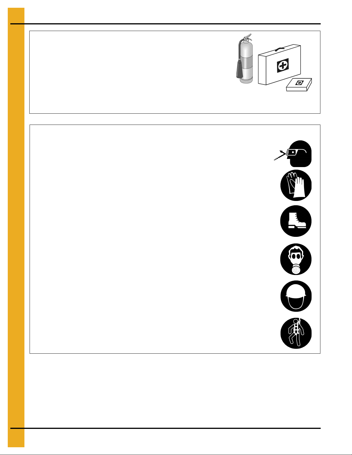
Prepare for Emergencies
Be prepared if fire starts.
Keep a first aid kit and fire extinguisher handy.
Keep emergency numbers for doctors, ambulance service,
hospital, and fire department near your telephone.
Keep Emergency Equipment
Quickly Accessible
Wear Protective Clothing
Wear close-fitting clothing and safety equipment appropriate
to the job.
Remove all jewelry.
Tie long hair up and back.
Wear safety glasses at all times to protect eyes from debris.
Wear gloves to protect your hands from sharp edges on plastic
or steel parts.
Wear steel-toed boots to help protect your feet from falling
debris. Tuck in any loose or dangling shoestrings.
A respirator may be needed to prevent breathing potentially
toxic fumes and dust.
Wear a hard hat to help protect your head.
Wear appropriate fall protection equipment when working at
elevations greater than six feet (6').
Eye Protection
Gloves
Steel-Toed Boots
Respirator
Hard Hat
Fall Protection
8 PNEG-1000 2.66" Commercial Tank Stiffener and Sidewall

2. Safety
Safety Sign-Off Sheet
As a requirement of O.S.H.A., it is necessary for the employer to train the employee in the safe operating
and safety procedures for this fan. This sign-off sheet is provided for your convenience and personal
record keeping. All unqualified persons are to stay out of the work area at all times. It is strongly
recommended that another qualified person who knows the shut down procedure be in the area in the
event of an emergency.
Date Employee Name Supervisor Name
PNEG-1000 2.66" Commercial Tank Stiffener and Sidewall 9

2. Safety
Proper Storage of Grain Bin/Silo Materials Prior to Construction
Wet storage stain (rust) will develop when closely packed bundles of galvanized material, such as sidewall
and roof sheets, have moisture present. Inspect roof and sidewall bundles on arrival for any moisture. If
moisture is present, it must not be allowed to remain between the she ets. Separate the sheets or panels
immediately and wipe them down. Spray with a light oil or diesel fuel.
If possible, sidewall bundles, roof sheets and other closely packed galvanized materials should be stored
in a dry, climate controlled building. If outdoor storage is unavoidable, the materials should be stored so
that they are raised above the ground and vegetation. Any stacking an d spacing mat erials sho uld not be
corrosive or wet. Be sure to protect materials from the weather, but permit air movement around the
bundles if possible.
Storing roof bundles and sidewall sheets at a slight incline can also help minimize the presence of
moisture. Storing the bundles with the center of the dome up (like an arch) is one option for minimizing
moisture during storage. Sidewall bundles can also be stored on edge but must be secured so that they
do not fall over and cause injury.
If “white rust” or “wet storage stain” occurs, contact the manufacturer imme diately about ways to minimize
the adverse effect upon the galvanized coating.
10 PNEG-1000 2.66" Commercial Tank Stiffener and Sidewall

2. Safety
General Information
Read this manual carefully. This manual will provide instructions on building the sidewall and stiffeners.
You will also need to consult other instructions in building the tank. These include, but may not be
limited to:
A stiffener and sidewall gauge layout chart. If such a chart is not included with this manual, contact GSI.
Roof instructions must be followed. The roof construction manual (PNEG-1092) will contain instructions
for 60' diameter and smaller bins. See appropriate individual diameter instructions for other diameters.
Ladders, roof stairs, roof handrails and other products are covered by separate instruction manuals.
Consult the appropriate accessory manual.
Areation systems and transitions are to be installed according to the instructions provide d with the system
or transition.
Anchor bolt placement details are provided in the GSI concrete recommendation manual (PNEG-318).
See this manual.
Tools for Construction
1. Combination wrench set 7/16" to 1".
2. Alignment punches 12" long.
3. Hammer.
4. Screw drivers - standard and philips.
5. 3/8" Drive socket set and ratchet.
6. 1/2" Drive socket set and ratchet.
7. Nail aprons or tool pouches to hold supplies.
8. Gloves for hand protection.
9. Tape measure.
10. 1/2" Drive electric or pneumatic impact gun.
11. 1/2" Drive impact socket set.
12. Lifting jacks.
13. Center pole roof support.
14. Step ladders.
15. Large C-clamp or welding V-grip for clamping.
Quantities required will depend on the number of workers and size of the bin/silo.
PNEG-1000 2.66" Commercial Tank Stiffener and Sidewall 11

2. Safety
Construction Procedures and Lifting Jack Usage
NOTE: The roof and top ring or 2 rings will be installed prior to the beginning of bin lifting/jacking
procedures. Refer all other procedures on sidewall and stiffener installation prior to the start
of construction.
1. Consider the starting location of the bin, relative to the location of doors and other accessories.
Proper placement of lifting jacks in relationship to anchor bolts could make a difference in final
locations. Note that the sidewall sheets will be staggered.
2. The bin is lifted by the use of lifting jacks. Lifting jacks are used to slowly and evenly lift the bin during
construction. Lifting jacks must be properly sized and designed to carry all dead and live loads and
job site conditions associated with the construction of the bin.
The number of lifting jacks required is best determined by personal experience and expertise.
Factors such as bin size, jack design, construction conditions, support surface, etc., are all to be
considered when deciding how many to use. If in doubt, use one jack on every sheet. The lifting jack
must be adequate to carry all loads. Heavy duty jacks, generally hydraulic or electric powered in the
case of large bins, should be used for commercial installation. All jacks should be secured with
braces or otherwise maintained in a stable condition.
Lifting of the bins should not be done under windy conditions.
Follow the jack manufacturers recommendations on capacity and operations.
3. Lifting brackets must be attached through the stiffener bolt holes. Normally you will need to attach to
at least four (4) bolts per stiffener.
4. Raise the bin just high enough to assemble the next ring. When lifting the bin, all jacks must lift at
an equal rate. Monitor the lift to ensure even lifting is occurring.
5. To the inside of the first ring, bolt the next ring. Be sure to stagger the sheets and select the proper
gauge material.
6. Lower the bin onto the foundation after assembling and tightening bolts on the new ring or rings.
7. Attach stiffeners to the body sheets every two (2) tiers (on the external surface of the bin). You may
want to leave sheets loose to make the attachment of the stiffeners easier.
8. Now re-bolt the lifting brackets to the lowest ring in place thus far. Continue ring additions by
repeating Steps 5 and 6.
9. Add inside and outside ladders as you continue to raise the bin. (Refer to the manual supplied with
the ladder.)
10. Lower the tank and secure to the foundation before leaving the job site.
11. At the completion of the tank, set stiffeners over the anchor bolts and measure the tank to ensure it
is in a round condition. Consult with GSI for questions on tolerances.
NOTE: For 2 ring doors or vehicle traffic doors special placement issues may apply. Consult the special
instructions provided with 2 ring doors or vehicle traffic doors for these options.
12 PNEG-1000 2.66" Commercial Tank Stiffener and Sidewall
3. Safety Decals
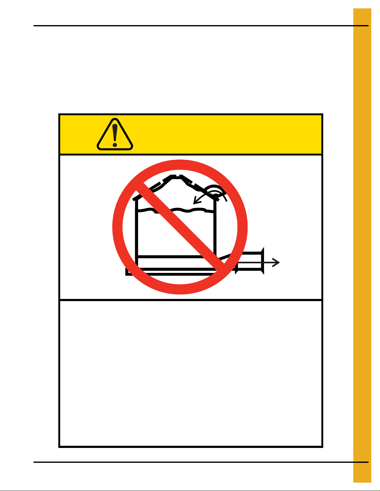
Excessive vacuum (or pressure) may
damage roof. Use positive aeration
system. Make sure all roof vents are
open and unobstructed. Start roof
fans when supply fans are started.
Do not operate when conditions exist
that may cause roof vent icing.
DC-969
CAUTION
GSI Group, Inc. 217-226-4421
The manufacturer does not warrant any roof damage caused by excess ive v acuum or internal
pressure from fans or other air moving systems. Adequate ventilation and/or “makeup air”
devices should be provided for all powered air handling systems. The manufacturer does not
recommend the use of downward flow systems (suction). Severe roof damage can result from
any blockage of air passages. Running fans durin g high humidity/cold weather conditions can
cause air exhaust or intake ports to freeze.
Roof Damage Warning and Disclaimer
PNEG-1000 2.66" Commercial Tank Stiffener and Sidewall 13
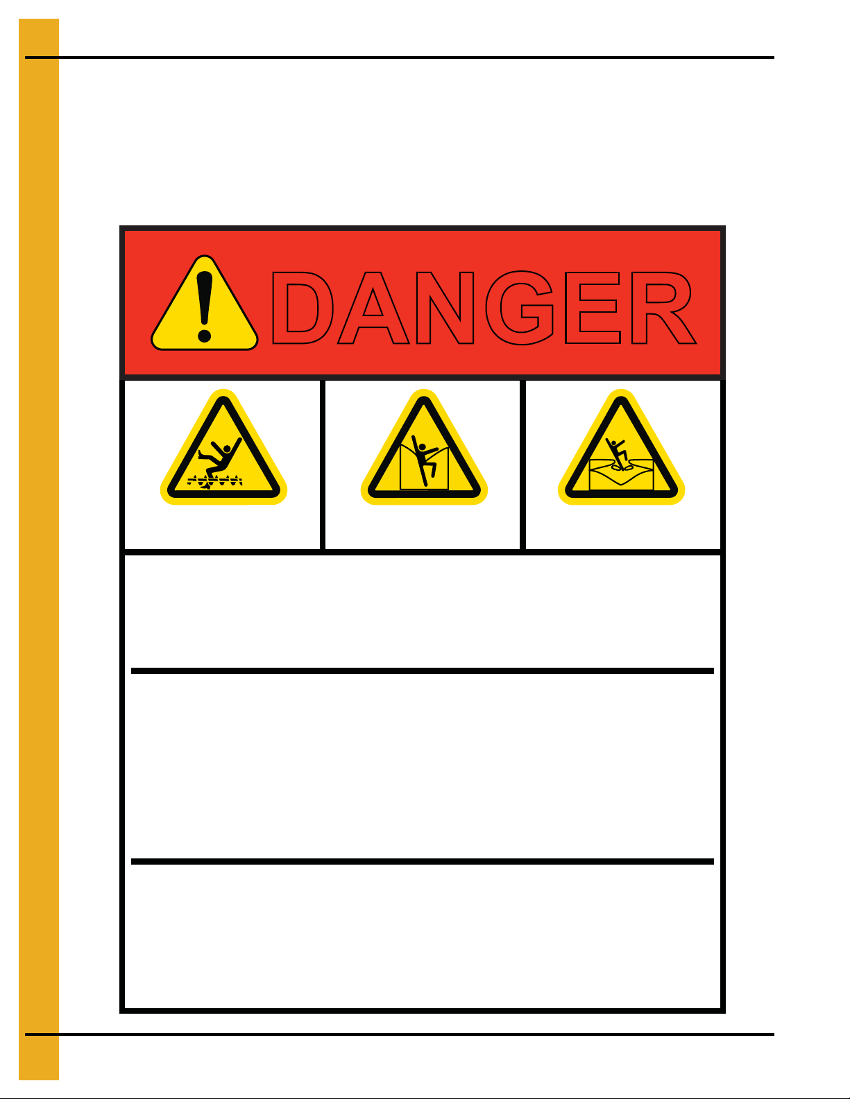
3. Safety Decals
Rotating flighting will
kill or dismember.
Flowing material will
trap and suffocate.
Crusted material will
collapse and suffocate.
DANGER
Keep clear of all augers.
DO NOT ENTER this bin!
If you must enter the bin:
1. Shut off and lock out all power.
2. Use a safety harness and safety line.
3. Station another person outside the bin.
4. Avoid the center of the bin.
5. Wear proper breathing equipment or respirator.
Failure to heed these
warnings will result in
serious injury or death.
DC-GBC-1A
GSI GROUP, INC. 217-226-4421
ATTENTION: The decal shown below should be present on the outside of the door cover of the 2 ring,
24" porthole door cover and roof manway cover. If a decal has been damaged or is missing in any of these
locations, contact the manufacturer for a free replacement decal.
GSI Decals
1004 E. Illinois St.
Assumption, IL. 62510
Phone: 1-217-226-4421
14 PNEG-1000 2.66" Commercial Tank Stiffener and Sidewall
3. Safety Decals
ATTENTION: The decal shown below should be present on the outside of the door cover of the 2 ring,
24" porthole door cover and roof manway cover. If a decal has been damaged or is missing in any of these
locations, contact the manufacturer for a free replacement decal.
GSI Decals
1004 E. Illinois St.
Assumption, IL. 62510
Phone: 1-217-226-4421
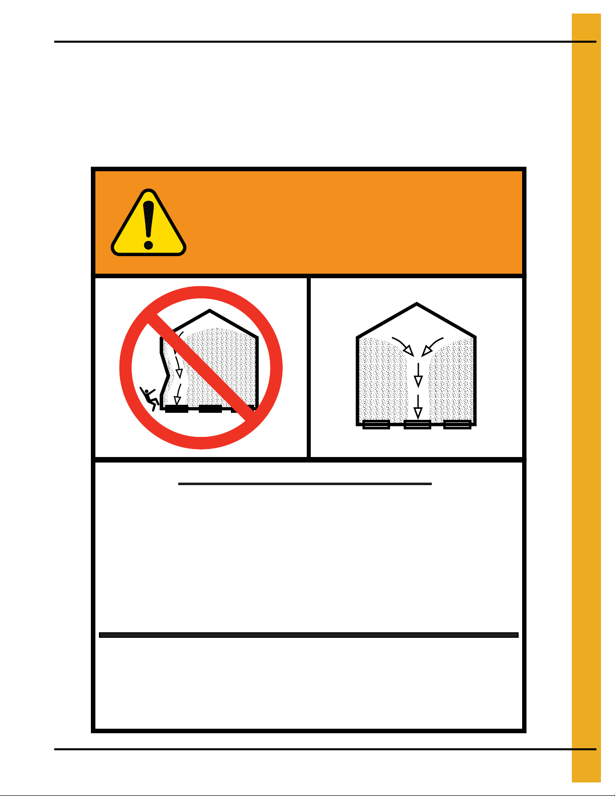
WARNING
UNLOADING INSTRUCTIONS:
1. Use CENTER FLOOR OUTLET ONLY until NO grain
remains above this outlet.
2. Side floor outlets to be used ONLY when above
condition is satisfied.
3. Lock all side floor outlets to avoid accidental
premature use.
4. See manufacturers instructions for proper use of
factory supplied sidedraw (wall) discharge systems.
Failure to heed these warnings
could result in serious injury, death,
structural damage or collapse of tank.
GSI GROUP, INC. 217-226-4421
PNEG-1000 2.66" Commercial Tank Stiffener and Sidewall 15
DC-GBC-2A
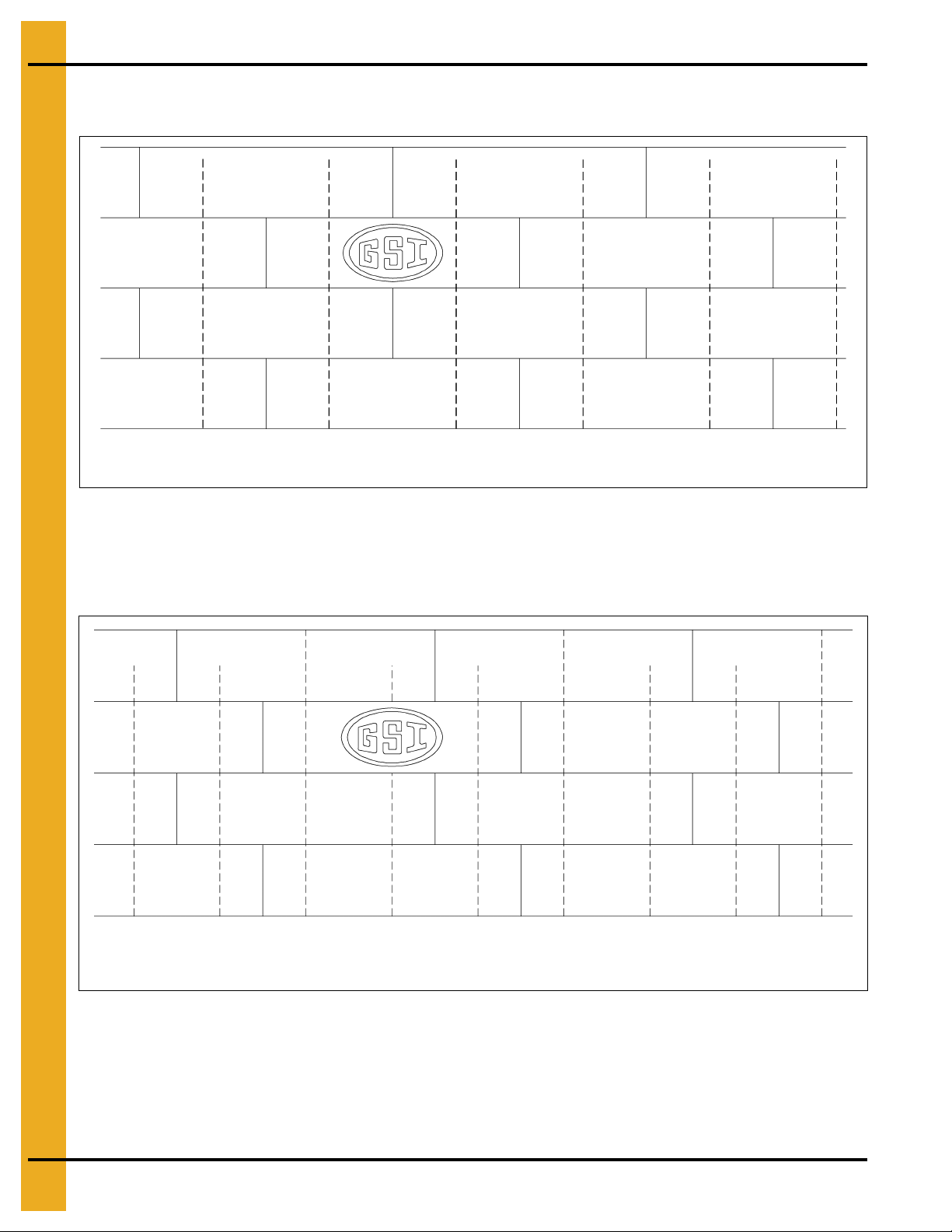
4. Decal Sheet Placement
NOTE: Dashed lines represent stiffener locations.
NOTE: Dashed lines represent stiffener locations.
NOTE: The decal sheets are located in the second ring from the top. They are to be spaced evenly around
the diameter of the bin.
Figure 4A 2 Post (Two (2) rows of stiffeners used on each sidewall sheet.)
NOTE: On 3 post bins the top ring is not normally stiffened except for 42' diameter and larger bins with
stiffeners, (one per sidewall panel). Refer stiffener to sidewall attachment detail and specific gauge
sheet for the bin.
Figure 4B 3 Post (Three (3) rows of stiffeners used on each sidewall sheet.)
16 PNEG-1000 2.66" Commercial Tank Stiffener and Sidewall
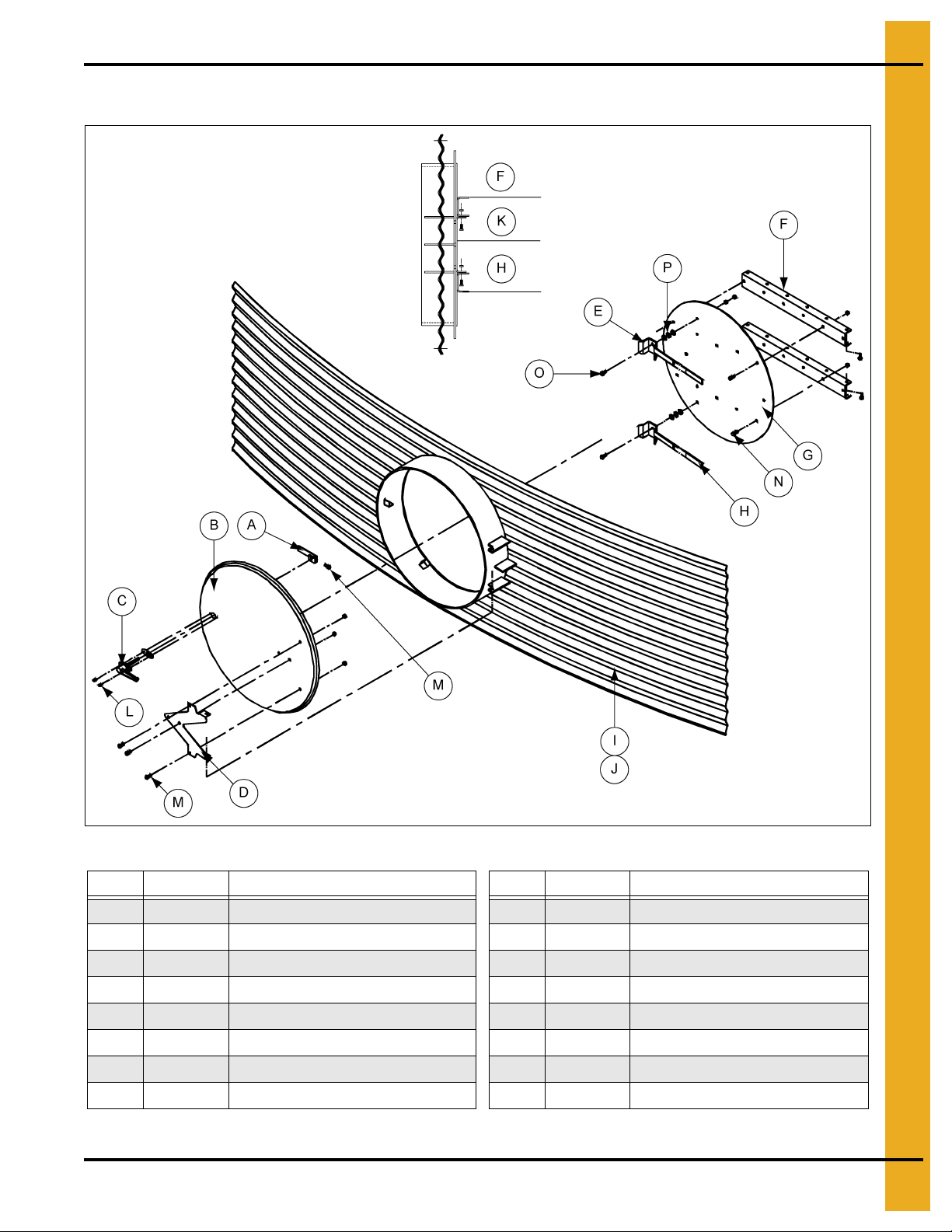
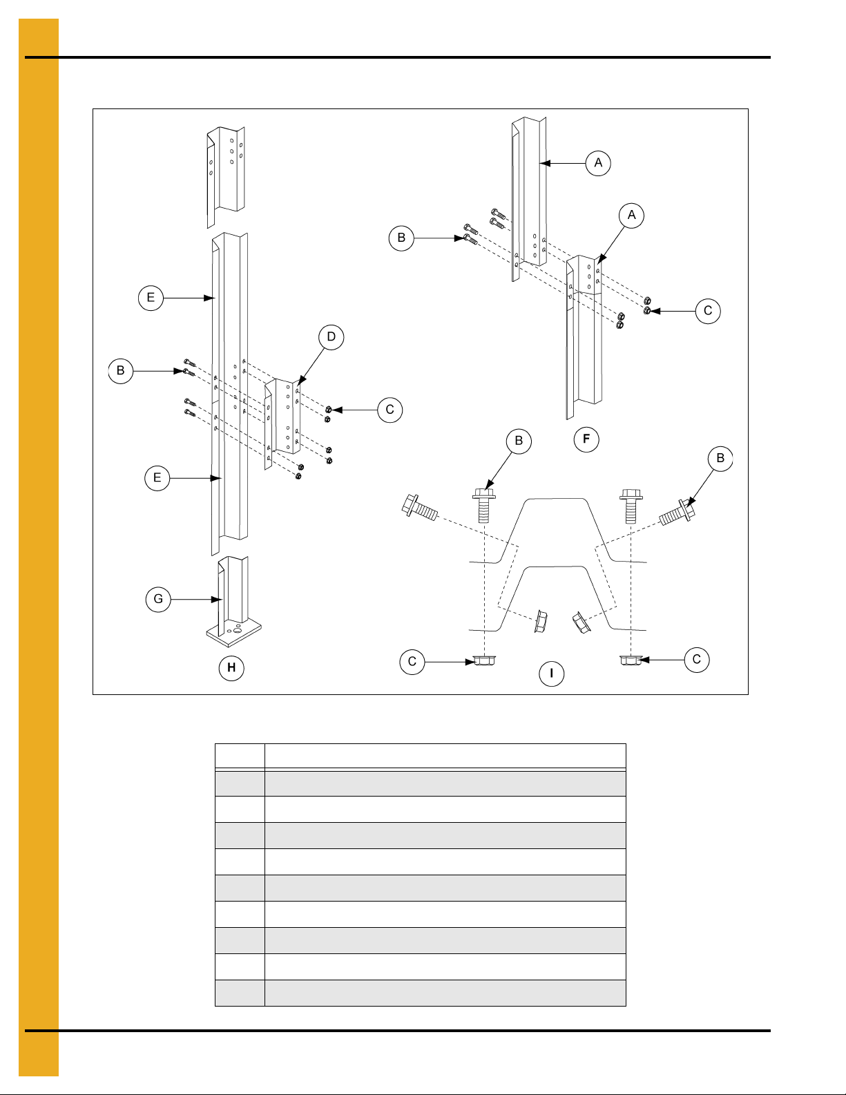
5. Access Door Weldment Assembly
Assembled
side detail
Access Door Weldment Assembly Hardware Package (PLS-41985)
** The quantity of 3/8" washers needed may vary depending on the sidewall gauges.
PNEG-1000 2.66" Commercial Tank Stiffener and Sidewall 17
Figure 5A
Ref # Part # Description Ref # Part # Description
A ACD-4514 Latch Bar I SS-721 1 Access Door Weldment
B ACD-4531 Door Cover
C ACD-4513 Access Door Handle K ACD-4509 Access Inner Door Hinge Bracket
D ACD-4505 Access Door Hinge
E ACD-4515 Access Inner Door Handle (2) M 5/16" x 3/4" Bolt and Nut
F ACD-4549 Bottom Ring Inner Door Hinge (2)
G ACD-4548 Bottom Ring Access Inner Door O 3/8" x 1-1/2" Full Threads
H S-3867 Sleeve, Plastic Rod Door Handle (2)
J SS-7214 Access Door Weldment
L#10 Screw
N 3/8" x 1" Bolt
P ** 3/8" Washers (Use as needed)
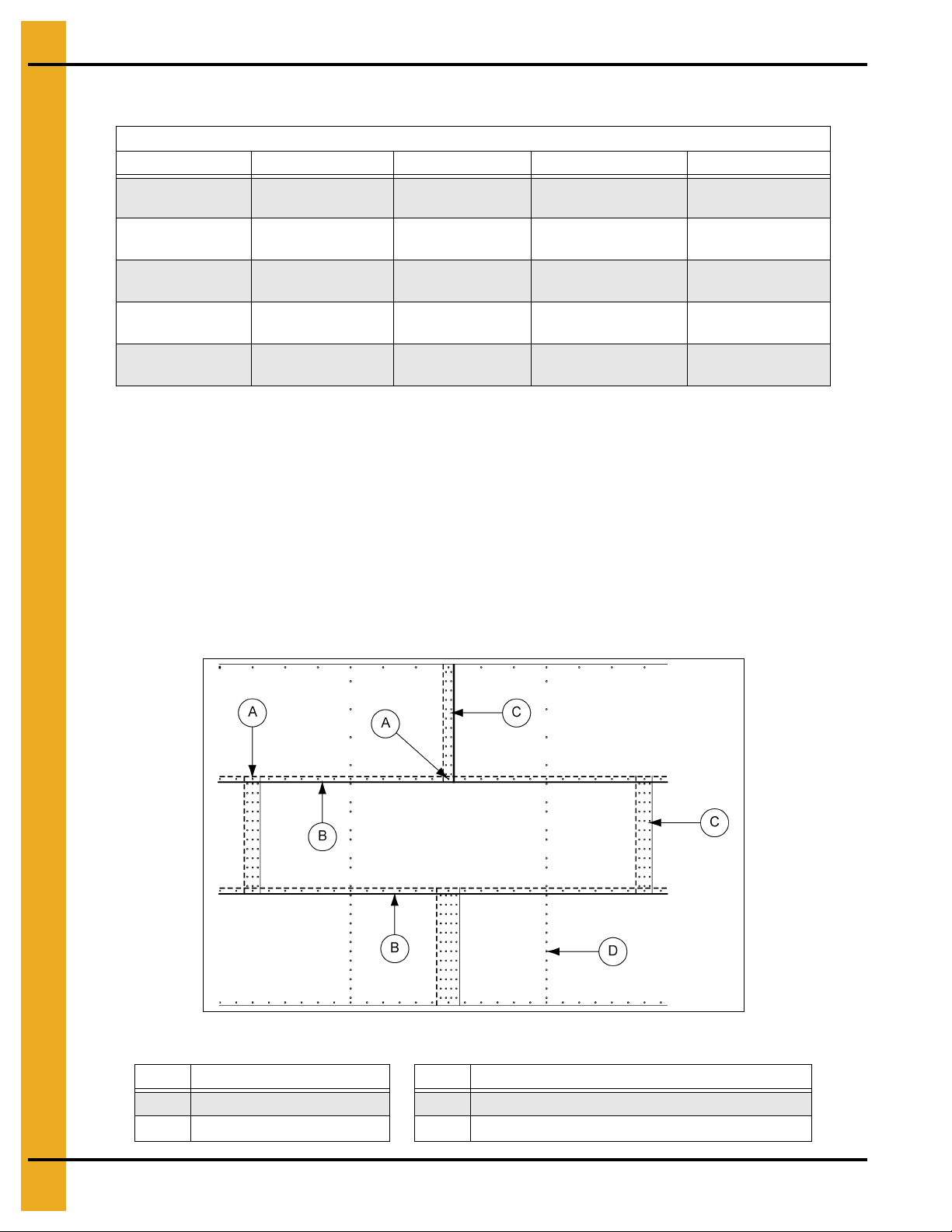
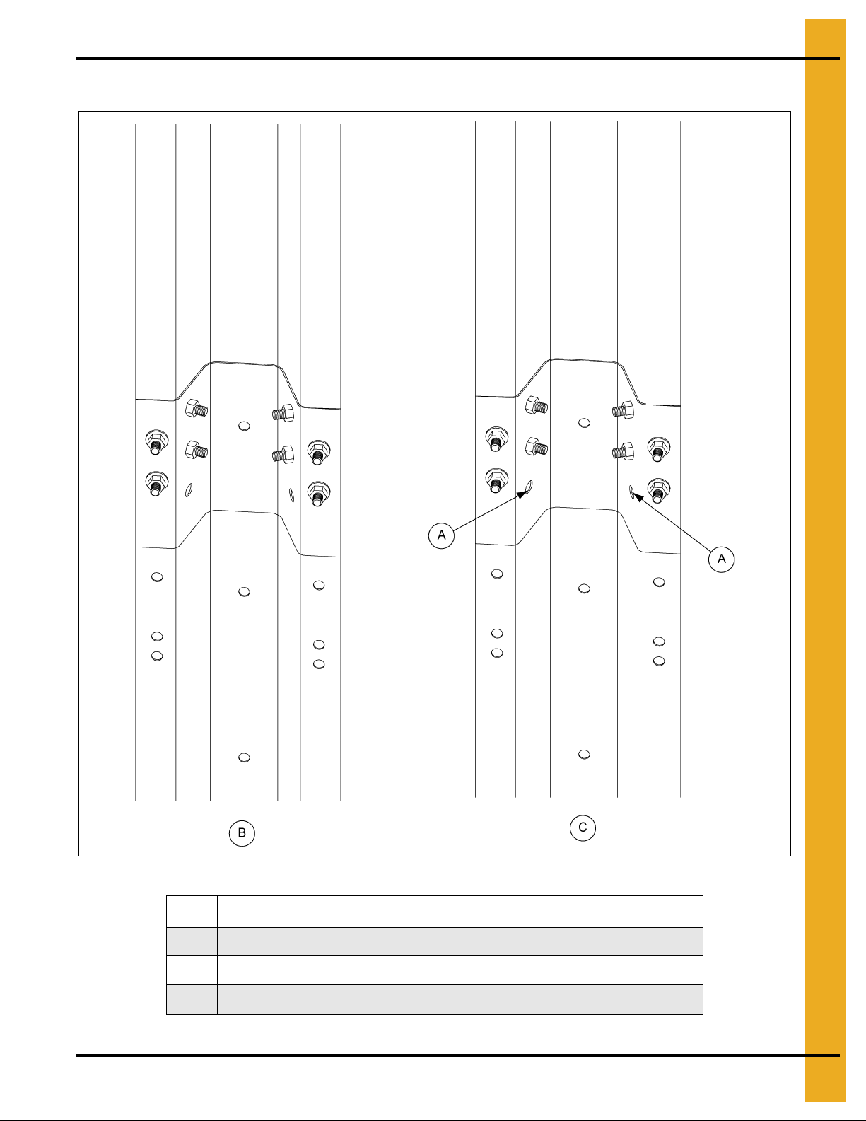
6. Bolting Requirements
2 Stiffeners per Sidewall Sheet
Sidewall Seams and Stiffener to Sidewall Bolt Usage.
Sidewall Gauge Horizontal Seam Vertical Seam Stiffener to Sidewall Overlap Seam
20-19
18T
17T-16T
15Q-14Q
13Q-10Q
5/16'' x 3/4''
[10]
5/16'' x 3/4''
[22]
5/16'' x 3/4''
[22]
5/16'' x 3/4''
[22]
3/8'' x 1''
[22]
1. T - Triple punched sheets (36 holes in vertical seam)
Q - Quad punched sheets (48 holes in vertical seams)
All bolts are standard bin bolts with neoprene washers. For horizontal and vertical seam bolts, the
bolt head and neoprene washers are on the outside of the bin. Refer stiffe ner instructions on stiffener
to sidewall bolt usage on Page 34 and Page 58.
5/16'' x 3/4''
[24]
5/16'' x 3/4''
[36]
5/16'' x 3/4''
[36]
5/16'' x 3/4''
[48]
3/8'' x 1''
[48]
3/8'' x 1''
[8]
3/8'' x 1''
[16]
3/8'' x 1''
[24]
3/8'' x 1''
[24]
3/8'' x 1''
[24]
5/16'' x 3/4''
[2]
5/16'' x 3/4''
[2]
5/16'' x 3/4''
[2]
5/16'' x 3/4''
[2]
3/8'' x 1''
[2]
2. Hardware part numbers
5/16'' x 3/4'' - S-275
3/8'' x 1'' - S-455
3. See Pages 34-37 and Pages 58-61 for special instructions on stiffener to sidewall bolt usage for
stiffener splices and laminated stiffeners.
4. Use 5/16'' bolts and nuts when joining 14 gauge to 13 gauge on horizontal seams.
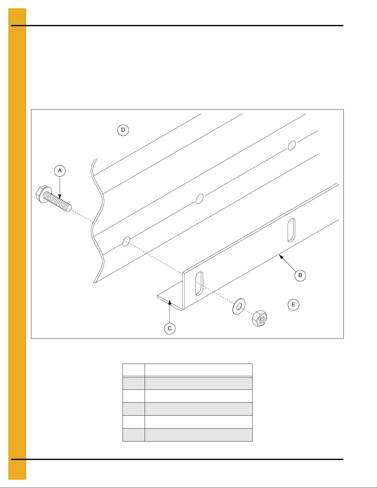
Figure 6A As Viewed from Outside (18 Gauge Sidewall Sheet)
Ref # Description
A Overlap Seam C Vertical Seam
B Horizontal Seam
Ref # Description
D Stiffener to Sidewall Standard Stiffened Punched
18 PNEG-1000 2.66" Commercial Tank Stiffener and Sidewall
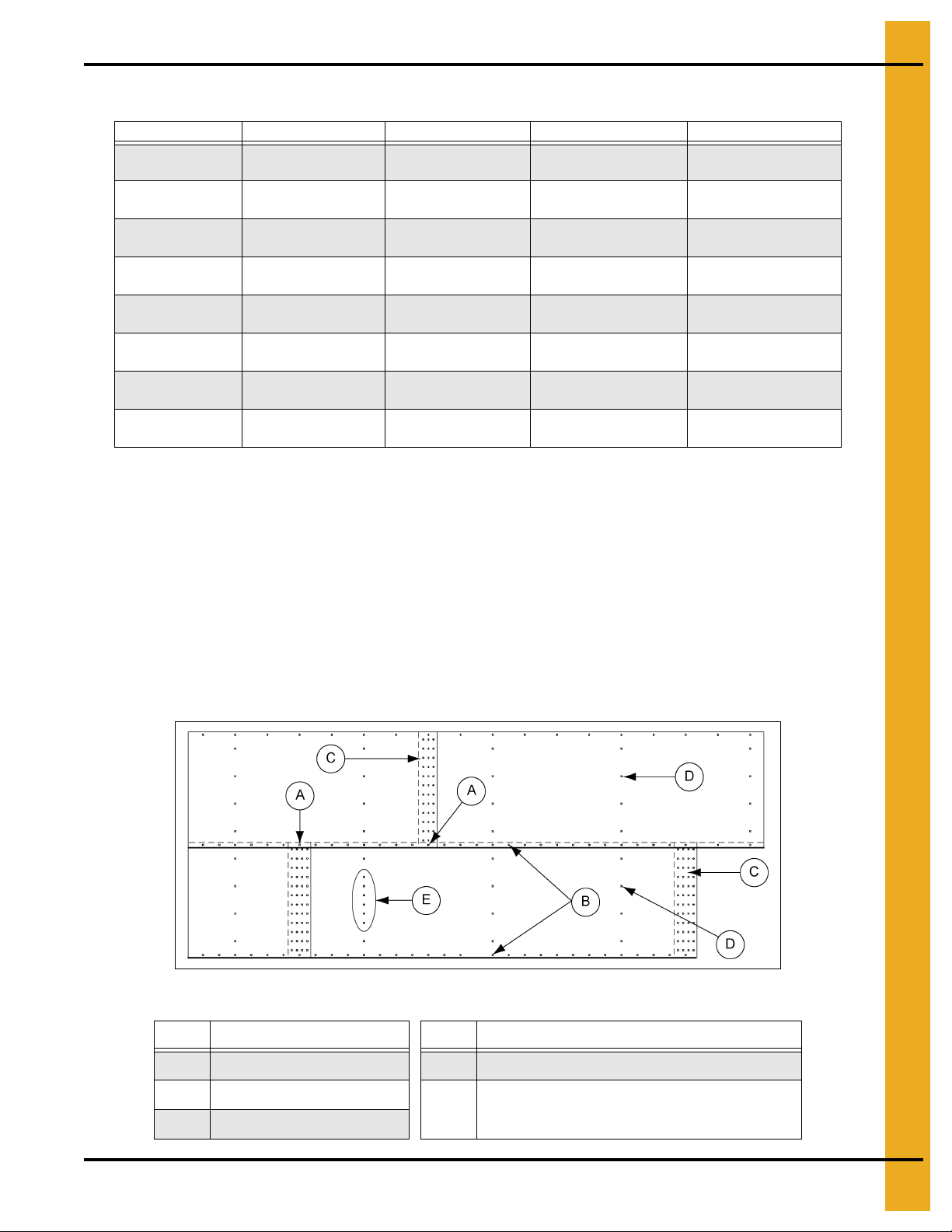
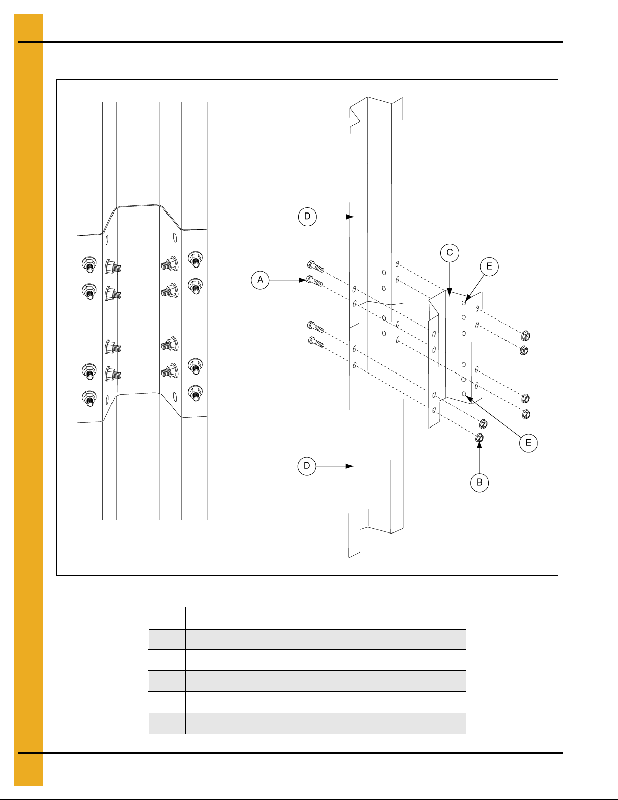
6. Bolting Requirements
3 Stiffeners per Sidewall Sheet
Sidewall Gauge Horizontal Seam Vertical Seam Stiffener to Sidewall Overlap Seam
20-19
18T-16T
15Q-14Q
13Q-10Q
9Q-8Q
6Q-11QL
10QL
9QL-8QL*
5/16'' x 3/4''
[10]
5/16'' x 3/4''
[10]
5/16'' x 3/4''
[10]
3/8'' x 1''
[22]
3/8'' x 1''
[22]
3/8'' x 1-1/2''
[22]
3/8'' x 1-1/2''
[22]
3/8'' x 1-1/2''
[24]
1. T - Triple punched sheets (36 holes in vertical seam)
Q - Quad punched sheets (48 holes in vertical seams)
QL - Laminated quad punched sheets (two (2) sheets of same gauge bolted together - all bolts are
standard bin bolts with neoprene washers. For horizontal and vertical seam bolts, the bolt head and
neoprene washers are on the outside of the bin. Refer stiffener instructions on stiffener to sidewall
bolt usage on Page 34 and Page 58.
5/16'' x 3/4''
[24]
5/16'' x 3/4''
[36]
5/16'' x 3/4''
[48]
3/8'' x 1''
[48]
3/8'' x 1''
[48]
3/8'' x 1-1/2''
[48]
3/8'' x 1-1/2''
[48]
7/16'' x 1-1/2''
[48]
3/8'' x 1''
[12]
3/8'' x 1''
[12]
3/8'' x 1''
[12]
3/8'' x 1''
[12]
3/8'' x 1-1/2''
[12]
3/8'' x 1-1/2''
[12]
3/8'' x 1-1/2'' ***
[24]
3/8'' x 1-1/2'' ***
[24]
5/16'' x 3/4''
[2]
5/16'' x 3/4''
[2]
5/16'' x 3/4''
[2]
3/8'' x 1''
[2]
3/8'' x 1-1/2''
[2]
3/8'' x 1-1/2''
[2]
3/8'' x 1-1/2''
[2]
3/8'' x 2''
[6]
2. Hardware part numbers
5/16'' x 3/4'' - S-275; 3/8'' x 1'' - S-455; 3/8" x 1-1/2" - S-5060; 7/16" x 1-1/2" - S-9464.
3. See Pages 34-37 and Pages 58-61 for special instructions on stiffener to sidewall bolt usage for
stiffener splices and laminated stiffeners.
4. Use 5/16" bolts and nuts when joining 14 to 13 gauge on horizontal seams.
Figure 6B As Viewed from Outside
Ref # Description Ref # Description
A Overlap Seam D Stiffener to Sidewall Standard Stiffened Punched
B Horizontal Seam
C Ve rtical Seam
Stiffener to sidewall (close punched) sheets are
E
close punched for stiffeners.
PNEG-1000 2.66" Commercial Tank Stiffener and Sidewall 19
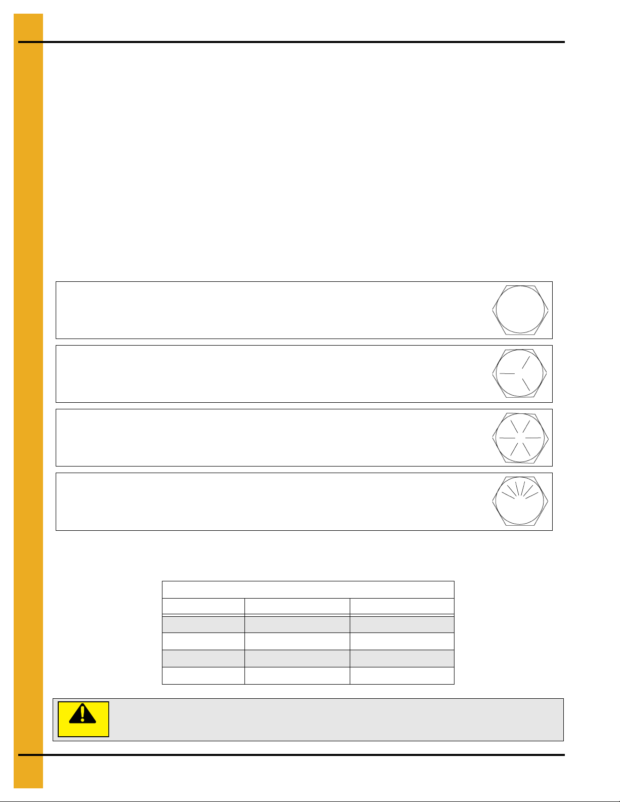
6. Bolting Requirements
NOTE: Grade 2 bolts are designated with a plain head.
NOTE: Grade 5 bolts are designated by three (3) slash marks on the head.
NOTE: Grade 8 bolts are designated by six (6) slash marks on the head.
NOTE: Grade 8.2 bolts are designated by six (6) slash marks on the head in a
sunrise pattern.
Under no condition shall any other bolts be substituted for those supplied by
grain systems.
* 105' diameter, 28 ring and taller tanks will utilize 7/16" x 2-1/2" bolts in the vertical seam.
3/8" x 2" bolts are provided for the overlap connection in the horizontal seam.
See the 105' tall tank series manual PNEG-972 if building 105' tanks 28 rings or taller.
*** A 3/8'' x 2'' bolt may be needed at first stiffener to sidewall bolt.
Before bolting sheets together, apply a single strip of caulking on both sides and 12" on b oth sides of top
edge. DO NOT CAULK BOTTOM EDGE.
1. When attaching a 13Q sheet to a 14Q sheet, use the 5/16" x 3/4" bin bolt on horizontal seam.
2. When attaching an 6Q sheet to a 8Q sheet, use the 3/8" x 1" bin bolt in the horizontal seam.
3. All base sheets are bolted to the base angle with 5/16" x 1-1/4" bin bolts (independent of
sidewall gauge).
Hardware Requirements
IMPORTANT: Do not tighten bolts to exceed the torque specifications listed below.
Torque (ft. lbs.)
Bolt Size Minimum Maximum
5/16"-18 15 20
3/8"-16 35 42
7/16"-14 65 72
1/2"-13 95 105
CAUTION
20 PNEG-1000 2.66" Commercial Tank Stiffener and Sidewall
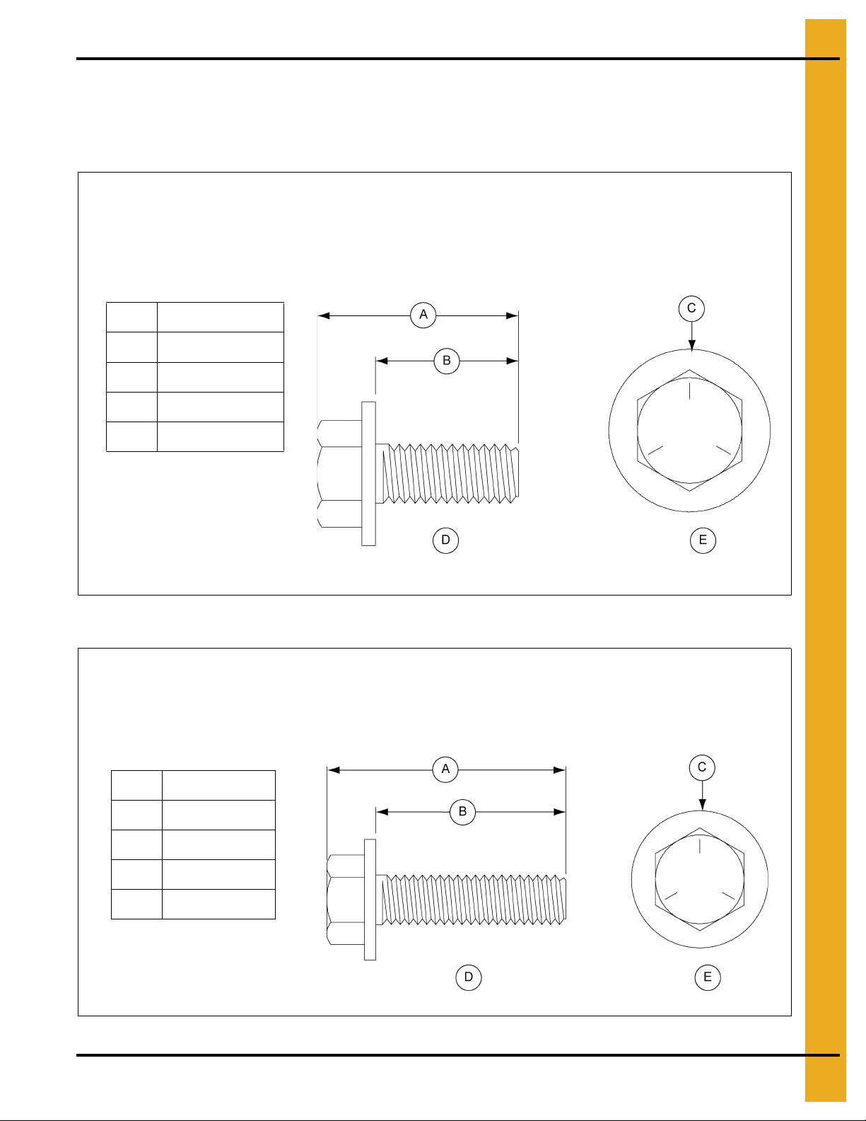
6. Bolting Requirements
0.3125" x 0.750" Pre-assembled with a steel backed neoprene washer .
This bolt is used to connect horizontal and vertical seams for 14 gauge and thinner sidewall sheet s
to each other. It is also used in attaching roof panels to the top sidewall sheet and attaching roof
panels and flashing to the center collar.
A 0.950" (2.41 cm)
B 0.750" (1.90 cm)
C Grade 5
D Side View
E Top View
0.3125" x 1.250" Pre-assembled with a steel backed neoprene washer .
This bolt is primarily used to connect roof panels together where they overlap. It is also used at the
bottom of the flat bottomed bins to attach the base angle to the sidewall sheet.
A 1.437" (3.64 cm)
B 1.250" (3.17 cm)
C Grade 5
D Side View
E Top View
Refer to 2.66" Commercial Tank Bolting Requirements for Complete
Bolt Usage.
S-275
S-277
PNEG-1000 2.66" Commercial Tank Stiffener and Sidewall 21
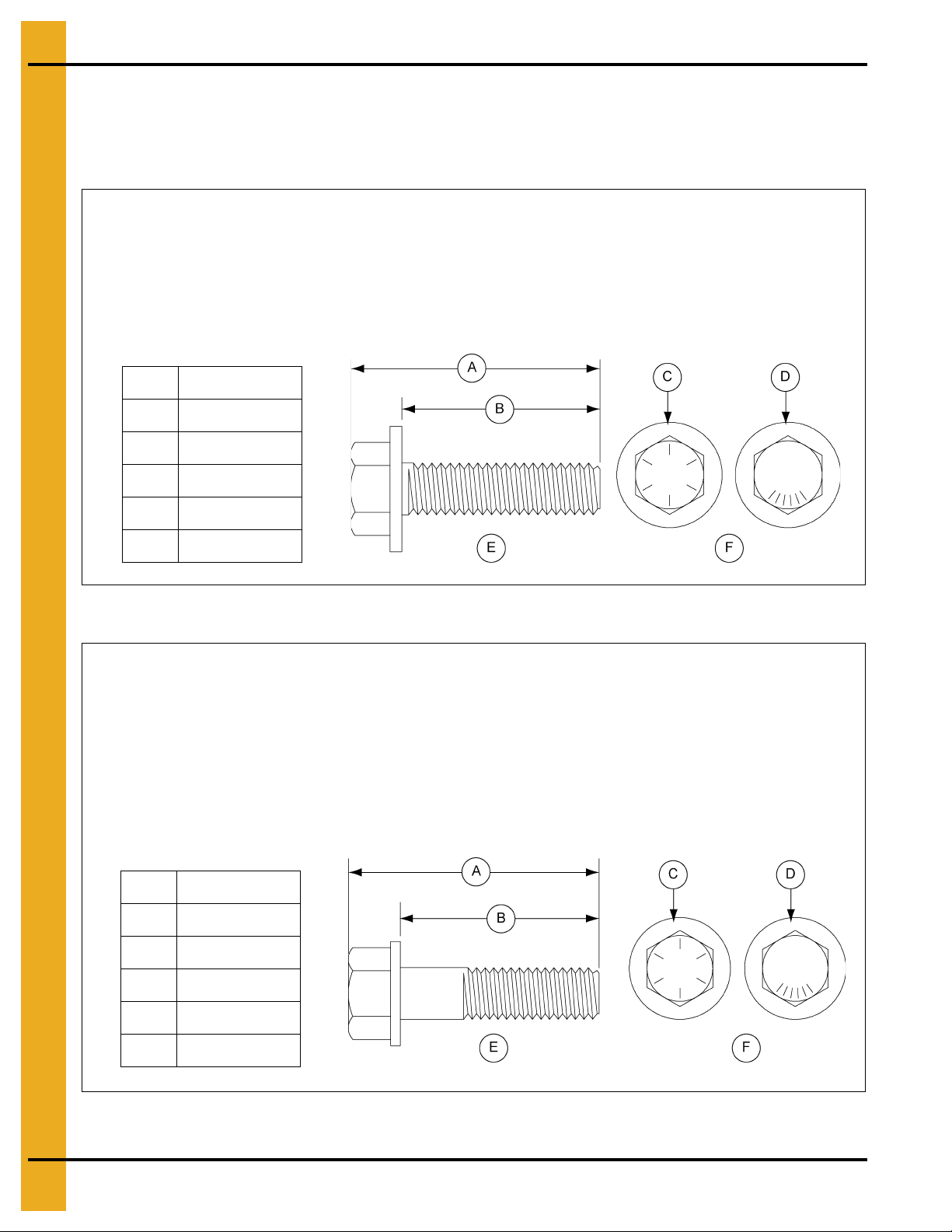
6. Bolting Requirements
0.375" x 1.000" Pre-assembled with a steel backed neoprene washer.
This bolt is used in horizontal and vertical seams for 13 gauge through 13 ga uge laminated sidewall
to attach the sheets to each other. It is also used to attach the stiffener to the sidewall sheet for up to
10 gauge sidewall. It is not used to splice the stiffeners together on the flanges where they connect
to each other or the splice plates. These are also used to attach the hopper panels to the hopper
support beam for the NCHT’s.
A 1.223" (3.10 cm)
B 1.000" (2.54 cm)
C Grade 8
D Grade 8.2
E Side View
F Top View
0.375" x 1.500" Pre-assembled with a steel backed neoprene washer.
It is used to connect the stiffener to the sidewall at locations where a splice plate is used to connect
the stiffener and to connect laminated stiffeners to the sidewall sheets. It is also used to bolt
stiffeners to 9 gauge and thicker sidewall. This bolt is also used to bolt horizont al and vertical seams
together on 12 gauge laminated and thicker and some overlap seams. It is only used to attach the
stiffener and the splice plate to the sidewall. The flanges where the stiffener bolts to the splices
plates use a different bolt (one without a rubber washer).
NOTE: 3/8" x 1-1/2" (S-5060) Bolts are provided for laminated stiffeners and splices.
A 1.725" (4.38 cm)
B 1.500" (3.81 cm)
C Grade 8
D Grade 8.2
E Side View
F Top View
Refer to 2.66" Commercial Tank Bolting Requirements for Complete
Bolt Usage. (Continued)
S-455
S-5060
22 PNEG-1000 2.66" Commercial Tank Stiffener and Sidewall
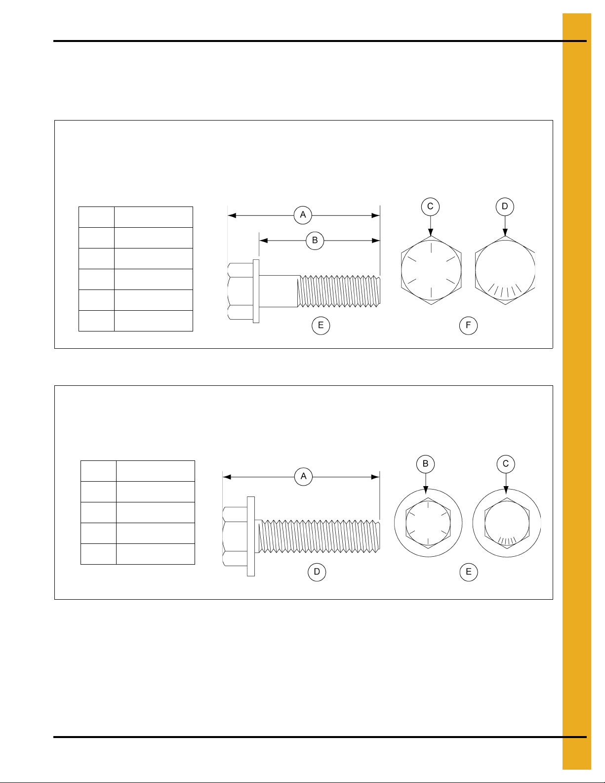
6. Bolting Requirements
0.375" x 2.000" Pre-assembled steel backed neoprene washer.
This bolt is used in overlapping seams on 8 gauge to 9 gauge laminated sidewall sheets and to
connect 6 gauge laminated rings to one another. It is also used to attach stiffener to sidewall on
6 gauge laminated sidewall sheets.
A 2.225" (5.65 cm)
B 2.000" (5.08 cm)
C Grade 8
D Grade 8.2
E Side View
F Top View
0.375" x 1.000" Hex flanged head without a plastic sealing washer.
This bolt is used to splice the stiffeners together on the flang es. A flange n ut is used on th e nut side
of the connection. They are also used on the roof rafter splices for commercial roof systems.
A 1.377" (3.49 cm)
B Grade 8
C Grade 8.2
D Side View
E Top View
Refer to 2.66" Commercial Tank Bolting Requirements for Complete
Bolt Usage. (Continued)
S-9445
S-7927
PNEG-1000 2.66" Commercial Tank Stiffener and Sidewall 23
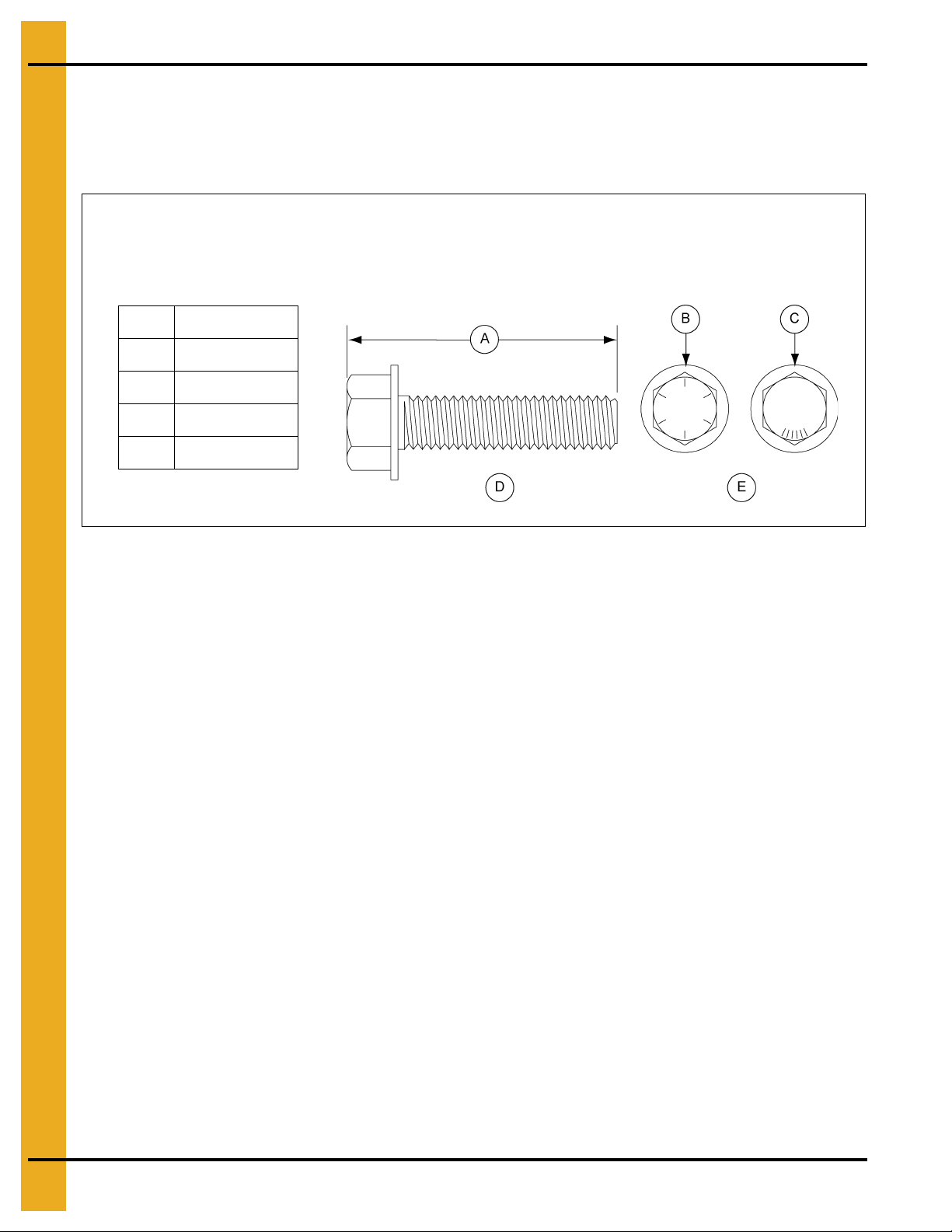
6. Bolting Requirements
0.375" x 1.500" Hex flanged head without a plastic sealing washer.
This bolt is used to attach the flanges of the 5 gauge base stiffener to the splice plates and splice
laminated stiffeners together. A flange nut is used on the nut side of the connection.
A 1.873" (4.75 cm)
B Grade 8
C Grade 8.2
D Side View
E Top View
Refer to 2.66" Commercial Tank Bolting Requirements for Complete
Bolt Usage. (Continued)
S-7928
NOTE: Outside stiffened bins with sidewall that is 10 gauge laminated or thicker will have three (3) sealing
washers per sheet provided loose. See the instructions for installation of these loose sealing
washers. Outside stiffened bins, 42' and larger diameter also may have loose sealing washers
provided for the roof rafter wall attachment bracket in the roof assembly hardware. See the
roof instruction manual on those washers and their installation. All other sealing washers are
pre-assembled onto the bolts. Steel flat washers are shipped loose. In the shell portion of the bin
the 5/16" steel flat washer (S-845) is used where the base angle attach es t o the sheet and some
are installed at the main eave clips. The 3/8" steel flat washers (S-248) are used at the stiffener
splices and at the laminated stiffener to sidewall locations and steel flat washers are also utilized
in some roof locations.
24 PNEG-1000 2.66" Commercial Tank Stiffener and Sidewall
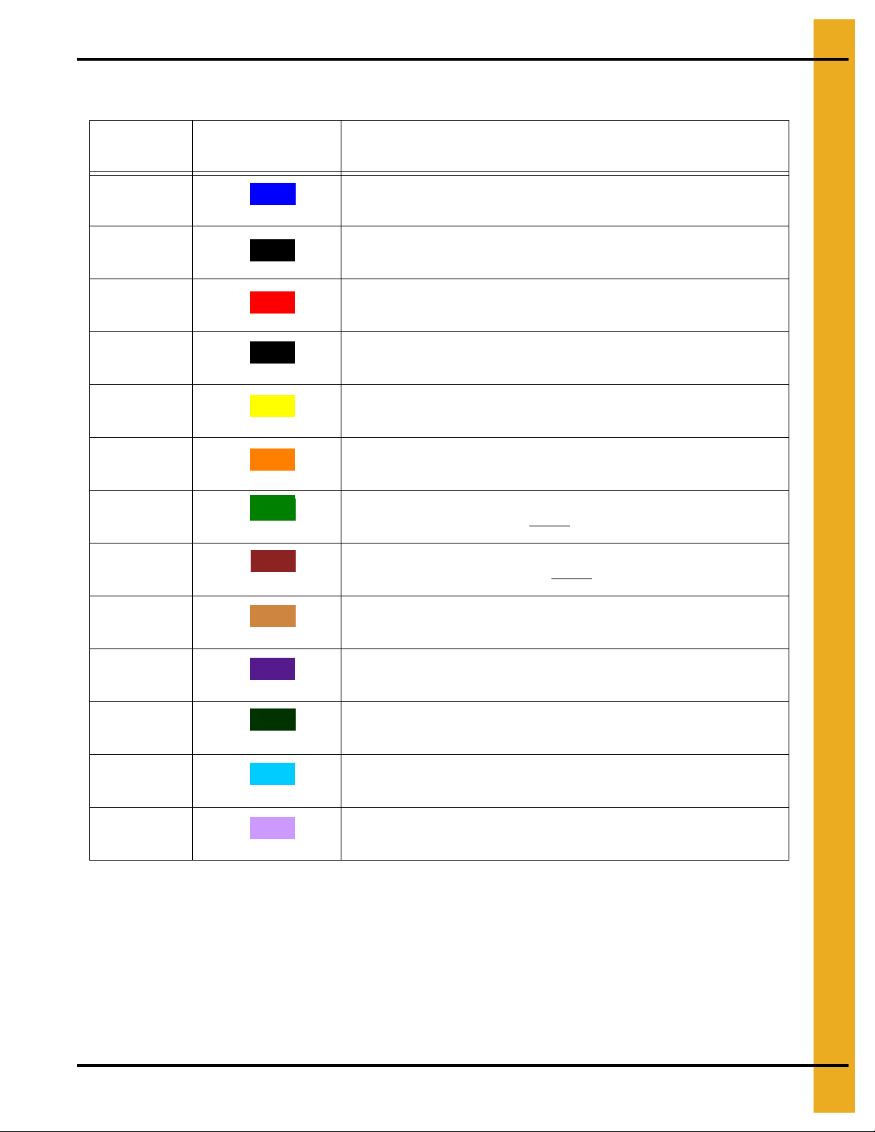
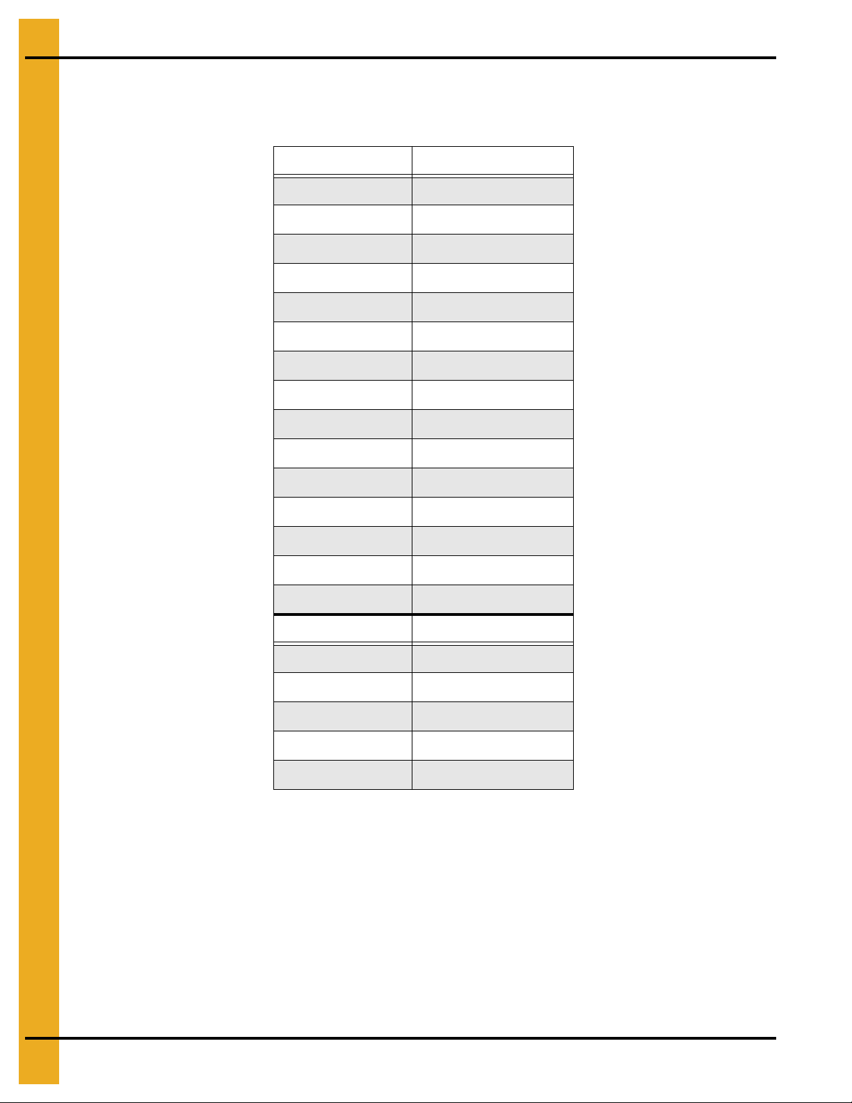
Color Chart for Bin Hardware Bucket Lids
Part # Color Description
6. Bolting Requirements
S-275 5/16" x 3/4" Bolt pre-assembled with a steel backed sealing washer
S-277 5/16" x 1-1/4" Bolt pre-assembled with a steel backed sealing washer
S-396 5/16" Hex nut
S-455 3/8" x 1" Bolt pre-assembled with a steel backed sealing washer
S-456 3/8" Hex nut
S-5060 3/8" x 1-1/2" Bolt pre-assembled with a steel backed sealing washer
S-7927 3/8" x 1" Hex flanged head bolt without
S-7928 3/8" x 1-1/2" Hex flanged head bolt without
Dark Blue
Black
Red
Grey
Yellow
Orange
Light Green
Dark Brown
sealing washer
sealing washer
S-8479 7/16" Special recessed nuts
S-9373 3/8" Hex flanged nuts
S-9444 7/16" x 2-1/2" Bolt pre-assembled with a steel backed sealing washer
S-9445 3/8" x 2" Bolt pre-assembled with a steel backed sealing washer
S-9470 7/16" x 2" Bolt pre-assembled with a steel backed sealing washer
Light Brown
Dark Purple
Dark Green
Light Blue
Light Purple
PNEG-1000 2.66" Commercial Tank Stiffener and Sidewall 25

7. Caulking Detail
Caulking Detail (Standard Non-Laminated Sheets)
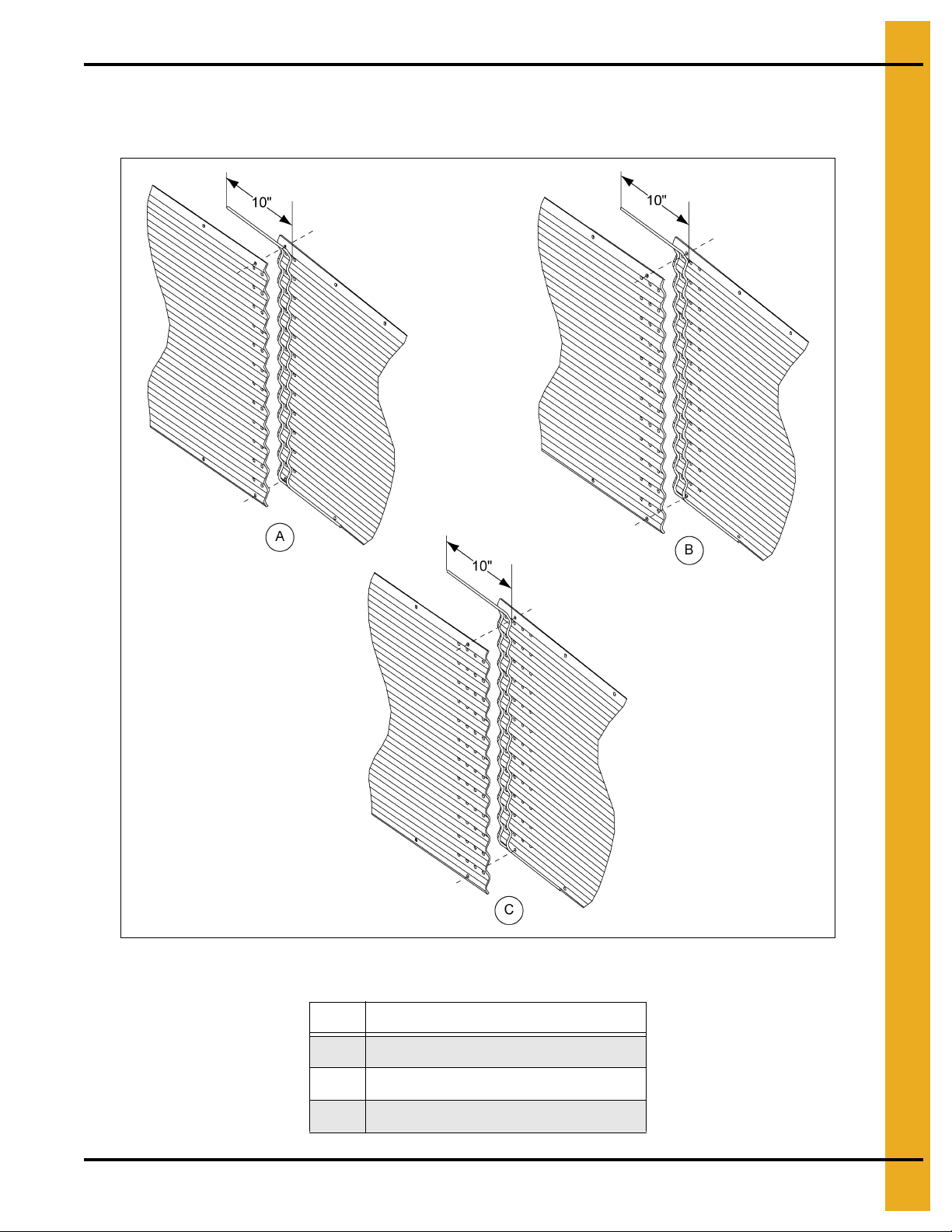
Apply one strip of caulking near the outside edge of the outer sheet and between the outer two (2) rows
of bolts, refer to Figure 7A. A strip of caulking 10" long, should be placed along the horizontal seams.
Before bolting the next ring into place, apply one strip of caulking 10" long on the front of the underlapped
sheet at each joint. Also, a 10" strip of caulking is to be placed along the lower horizo ntal edge of lapping
sheet at every vertical seam. This will fill the space that occurs between the holes caused by the
overlapping sheets. Additional 10" strips must be used to fill larger gaps that occur with heavier gauges
and laminated gauges.
Figure 7A Standard, Triple and Quad Punched Sidewall Sheets as Viewed from Outside
26 PNEG-1000 2.66" Commercial Tank Stiffener and Sidewall
7. Caulking Detail
Caulking Detail (Standard Non-Laminated Sheets) (Continued)
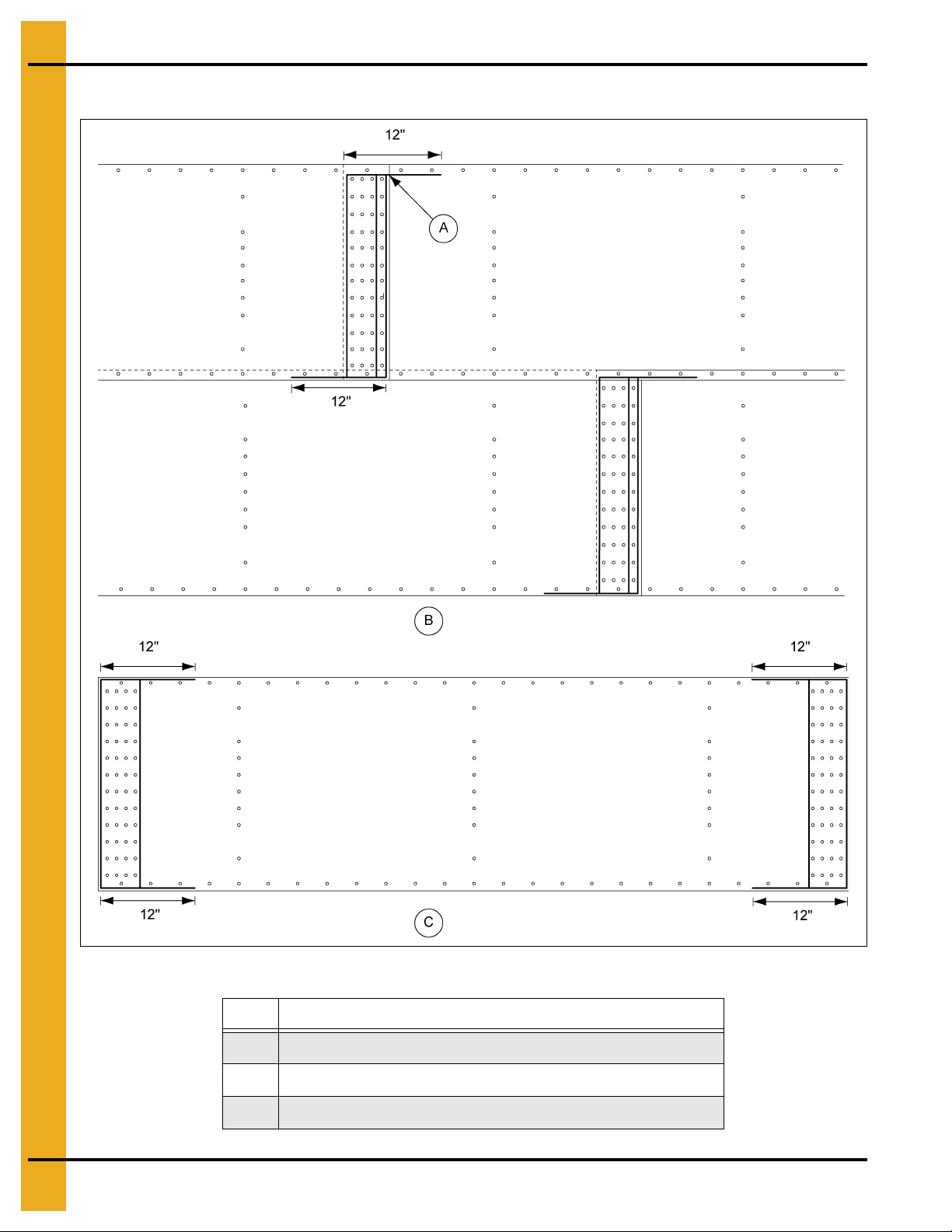
NOTE: See Figure 7B for additional details on laminated caulking.
Figure 7B As Viewed from Inside of Bin (Externally stiffened reverse-rolled sheets shown.)
Ref # Description
A Double Punch Caulking Detail
B Triple Punch Caulking Detail
C Quad Punch Caulking Detail
PNEG-1000 2.66" Commercial Tank Stiffener and Sidewall 27
7. Caulking Detail
Caulking Detail for Laminated Sheets
Figure 7C
Ref # Description
A Caulking
B Laminated quad punched sidewall sheets as viewed from outside.
C Caulking between laminated sheets.
28 PNEG-1000 2.66" Commercial Tank Stiffener and Sidewall
7. Caulking Detail
Caulking Detail for Laminated Sheets (Continued)
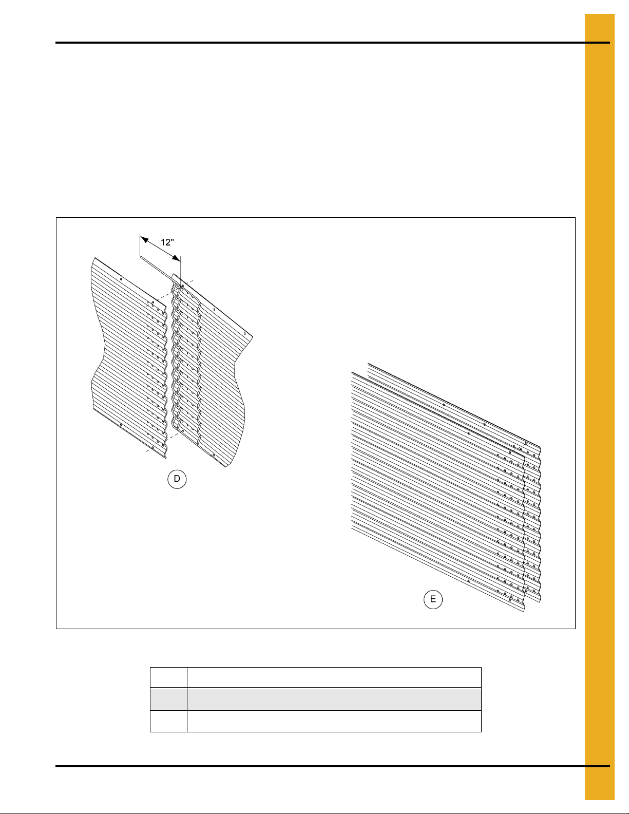
When bolting the two (2) assembled/laminated sheets to each other, apply one strip of caulking near the
outside edge of the outer sheet, between the outer two (2) rows of bolts and o utside the last row of bolts.
(See Figure 7D.) A strip of caulking 12" long should be placed along t he horizontal seams. Before bolting
the next ring into place, apply one strip of caulking 12" long on the front of the under lapped sheet at each
joint. Also, a 12" strip of caulking is to be placed along the lower horizontal edge of lapping sheet at the
vertical seam. This will fill the space that occurs between the holes caused by the overlapping sheets.
Additional 12" strips must be used to fill larger gaps that may occur with thicker gauges.
When assembling two (2) sheets to make a laminated sheet assembly, apply a row of caulk all around the
vertical seam. (See Figure 7D.)
Figure 7D
Ref # Description
D Caulking detail for assembled sheets as viewed from inside of bin.
E Laminated Sheet Detail (Caulking not shown.)
PNEG-1000 2.66" Commercial Tank Stiffener and Sidewall 29
8. Installation
Base Angle Installation
On the lower edge of the final bottom ring, attach the base angle ring utilizing 5/16" x 1-1/4" bin bolts.
Before the bolts are tightened, push the angle tight against the bottom edge of the sheet. Before
lowering the bin, apply the optional mastic sealer to the entire underneath side of the base angle.
(See Figure 8A.) Next, lower the bin onto the foundation and check for an adequate seal. If base sealer
strip is not used some other method should be utilized to seal the base ring to the concrete.
NOTE: Inside stiffened shown.
Figure 8A
Ref # Description
A 5/16" x 1-1/4" Bin Bolt
B Base Angle (B-6753)
C Mastic Sealer (Optional)
D Outside
E Inside
30 PNEG-1000 2.66" Commercial Tank Stiffener and Sidewall
8. Installation
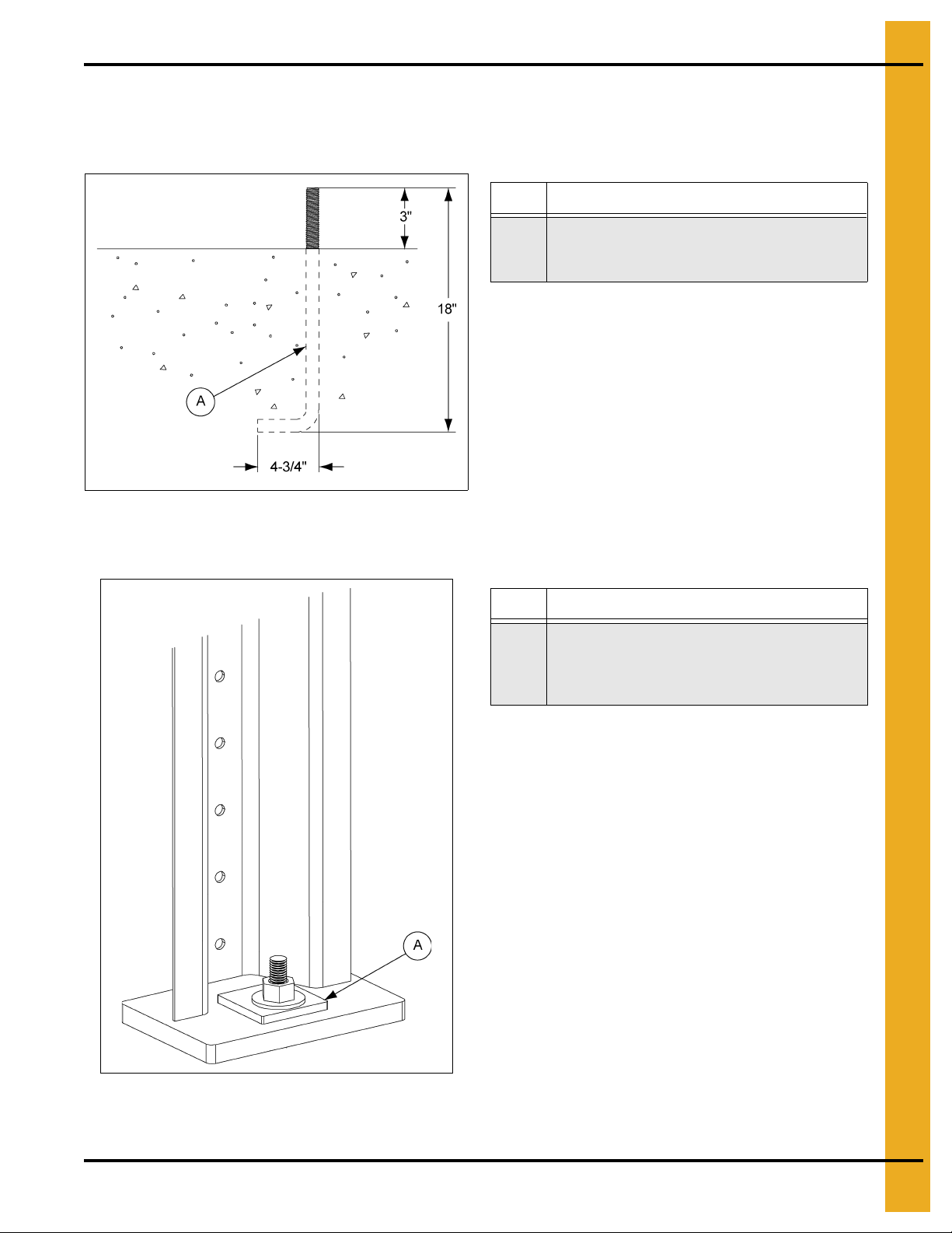
Anchor Bolt Detail
This is a minimum requirement for anchorage on standard tan ks. Refer to sidedraw instructions for special
anchorage details on Page 83.
Ref # Description
3/4" Diameter anchor bolt shown bolt assembly.
A
(B-4161 3/4" bolt assembly package.) 3/4" is
minimum diameter permitted.
Figure 8B
Anchor Bolt Washer Installation
Ref # Description
A square plate washer (provided) must be placed
in between the base plate and the anchor bolt
A
nut. 3/4" Anchor plate washer part # is HT-635.
1" Anchor plate washer part # is B-6756.
Figure 8C
PNEG-1000 2.66" Commercial Tank Stiffener and Sidewall 31
8. Installation
2.66" Sidewall Gauges
NOTE: Some colors are different than those used for stiffeners.
Sidewall Gauge Color Code
20 Red
19 Black/Yellow
18 Orange
17 Pink/Light Blue
16 Blue
15 Brown/Red
14 Green
13 Yellow/Blue
12 Black
11 Pink
10 Light Blue
9 Blue/Orange
8 Yellow
6White
5 Fluorescent Green
Laminated Sidewall Color Code
10 Light Blue/Gold
9 Blue/Orange/Gold
8 Yellow/Gold
6 White/Gold
5 Fluorescent Green/Gold
32 PNEG-1000 2.66" Commercial Tank Stiffener and Sidewall

2.66" Commercial Tank
Stiffener Instructions
Inside Stiffened Only
®
PNEG-1000 2.66" Commercial Tank Stiffener and Sidewall 33

9. Stiffener Instruction (Inside Stiffened)
2.66 Commercial Tank Stiffener Instructions Inside Stiffened Only
Universal Stiffener and Splice Hardware
Stiffeners Splicing Systems
12 Gauge to 12 Gauge
and Thinner
12 Gauge to 11 Gauge
through
8 Gauge to 5 Gauge, 6 Gauge
5 Gauge, 6 Gauge to 5 Gauge, 6 Gauge
5 Gauge to Laminated, Laminated to Laminated,
Laminated to Laminated Enhanced/Universal
Laminated Enhanced/Universal to Laminated Enhanced/Universal
Laminated Enhanced/Universal to Laminated Enhanced/Enhanced
Laminated Enhanced/Enhanced to
Laminated Enhanced/Enhanced
Splice Hardware Usage
(Not Including Sidewall to Splice Bolts)
Use SS-6966 or SS-7427 Splice 2 per Joint
Use SS-6966 or SS-7427 Splice 2 per Joint
Use SS-6966 or SS-7427 Splice 2 per Joint
Offset/Lapped Stiffener
No Separate Splices Plate
Use SS-7053 Splice
Color Code: Y ellow
Use SS-7053 Splice
Color Code: Y ellow
Use SS-7398 Splice 2 per Joint
Use SS-7398 Splice 4 per Joint
Stiffeners Splicing Systems Hardware Part # Description Qty
14 Gauge and 15 Gauge Offset Stiffener Joint
12 Gauge and 13 Gauge Offset Stiffener Joint
10 Gauge and 11 Gauge
8 Gauge and 9 Gauge
5 Gauge and 6 Gauge
Laminated
Laminated to Laminated Enhanced
Laminated Enhanced
SS-7053
Stiffener Joint
SS-7053
Stiffener Joint
SS-7053
Stiffener Joint
SS-6966 or SS-7427
Stiffener Joint
SS-6966 or SS-7427
and SS-7398
Stiffener Joint
SS-6966 or SS-7427
and SS-7398
Stiffener Joint
Stiffener to Sidewall Hardware Usage
Splicing Systems Hardware Part # Description
Stiffener to Sidewall
SS-7053
Splice to Sidewall
Laminated Stiffener to Sidewall
Laminated Enhanced Stiffener
to Sidewall
S-7927 3/8" x 1" 8
S-9373 3/8" Flange Nuts 8
S-7927 3/8" x 1" 10
S-9373 3/8" Flange Nuts 10
S-7927 3/8" x 1" 16
S-9373 3/8" Flange Nuts 16
S-7927 3/8" x 1" 20
S-9373 3/8" Flange Nuts 20
S-7928 3/8" x 1-1/2" 20
S-9373 3/8" Flange Nuts 20
S-7928 3/8" x 1-1/2" 30
S-9373 3/8" Flange Nuts 30
S-7928 3/8" x 1-1/2" 38
S-9373 3/8" Flange Nuts 38
S-7928 3/8" x 1-1/2" 42
S-9373 3/8" Flange Nuts 42
S-455 3/8" x 1"
S-456 3/8" Nuts
S-5060 3/8" x 1-1/2"
S-456 3/8" Nuts
S-5060 3/8" x 1-1/2"
S-9373 3/8" Flange Nuts
S-5060 3/8" x 1-1/2"
S-9373 3/8" Flange Nuts
34 PNEG-1000 2.66" Commercial Tank Stiffener and Sidewall

9. Stiffener Instruction (Inside Stiffened)
Commercial Stiffeners for 2.66'' Corrugation
Figure 9A
Ref # Part # Description Length
A SS-6929 2 Ring Laminated Stiffener 71.906'' (182.642 cm)
B SS-6976 Base Stiffener 80.094'' (203.438 cm)
C SS-7371 5E+5U Enhanced Laminated 2 Ring Stiffener 71.938" (182.723 cm)
D SS-6978 5+10 and 5+8 Laminated Base Weldment 88.094'' (223.758 cm)
E SS-7372 5E+5E Enhanced Laminated 2 Ring Stiffener 71.938" (182.723 cm)
F SS-7202 5+5 Laminated Base Weldment 87.719'' (222.806 cm)
G SS-6989 Offset Base Stiffener 87-1/8'' (180.260 cm)
H SS-7366 5E+5 Laminated Enhanced Base Weldment 88.844" (225.664 cm)
I SS-7362 5E+5E Laminated Enhanced Base Weldment 88.844" (225.664 cm)
PNEG-1000 2.66" Commercial Tank Stiffener and Sidewall 35

9. Stiffener Instruction (Inside Stiffened)
4" Typical
Commercial Stiffeners for 2.66'' Corrugation (Continued)
Figure 9B
Ref # Part # Description Length
A SS-7065 14 Gauge and 15 Gauge 2 Ring Stiffener 70.969" (180.260 cm)
B SS-6982 12 Gauge and 13 Gauge 2 Ring Stiffener 70.969" (180.260 cm)
C SS-7083 10 Gauge and 11 Gauge 2 Ring Stiffener 63.938" (162.401 cm)
D SS-6923 5 Gauge, 6 Gauge, 8 Gauge and 9 Gauge 2 Ring Stiffener 63.938" (162.401 cm)
E SS-7064 Offset 1 Ring Stiffener 38.969" (98.981 cm)
F SS-7066 1 Ring Top 12.469'' (31.671 cm)
G SS-7053 8 Gauge Splice 14'' (35.56 cm)
H SS-6966 or Laminated Back Plate Splice 22'' (55.88 cm)
H SS-7427 Laminated Back Plate Splice 11-3/4" (29.845 cm)
I SS-7398 Enhanced Back Plate Splice 14" (35.56 cm)
36 PNEG-1000 2.66" Commercial Tank Stiffener and Sidewall

9. Stiffener Instruction (Inside Stiffened)
2.66'' Corrugation Commercial Stiffeners Splice Details
When installing bottom stiffeners, you may find that in some cases the stiffener with base plate attached
will not rest on the foundation (due to unlevel foundation, etc.). Shim plates have been furnished and
should be used to fill opening between base plate and concrete.
IMPORTANT: If shim plates are not used where required, the downward pressure of the stiffeners will not
be transferred directly to the foundation and bin failure could result.
NOTE: Some colors are different than those used for sidewall sheets.
* NOTE: Only Orange on 1 ring stiffener.
Stiffener Color Code Chart
Stiffener Gauge Color Code
15 Red/Orange *
14 Green/Orange *
13 Dark Blue
12 Black
11 Pink
10 Light Blue
9 Purple
8Yellow
6 White
5 Fluorescent Green
5+12 Gold/Black
5+10 Gold/Light Blue
5+8 Gold/Yellow
5+5 Gold/Fluorescent Green
5E+5U Ochre/Gold/White
5E+5E Ochre/Gold/White/Brown
PNEG-1000 2.66" Commercial Tank Stiffener and Sidewall 37

9. Stiffener Instruction (Inside Stiffened)
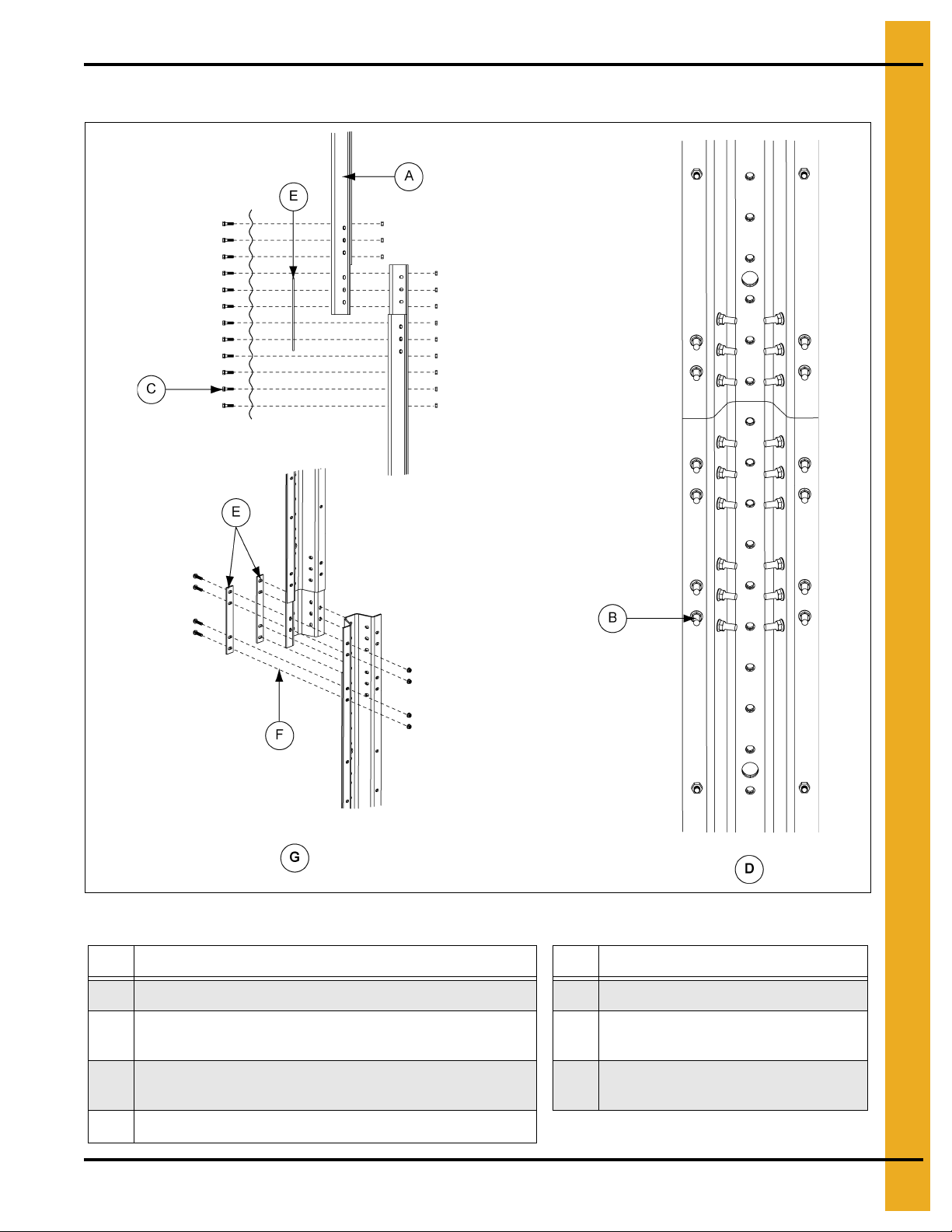
2.66'' Corrugation Commercial Stiffeners Splice Details (Continued)
Figure 9C
Ref # Description
A Standar d Offset Stiffener
B 3/8" Diameter Hex Flanged Head Bolt (No Sealing Washer)
C 3/8" Flange Nut
D Splice Plate 8 Gauge (SS-7053)
E 2 Ring Standard Stiffener
F Offset Joint Connection Detail
G Base Stiffener (SS-6976)
H Splice Plate Joint Detail (Non-Offset Joints)
I Splice Plate Joint (Top View)
38 PNEG-1000 2.66" Commercial Tank Stiffener and Sidewall

9. Stiffener Instruction (Inside Stiffened)
2.66'' Corrugation Commercial Stiffeners Splice Details (Continued)
Figure 9D
Ref # Description
A Bolt hole not used in 14 gauge and 15 gauge. Do not drill.
B 14 Gauge and 15 Gauge to 14 Gauge and 15 Gauge Offset Connection Detail
C 14 Gauge and 15 Gauge to 13 Gauge and 12 Gauge Offset Connection Detail
PNEG-1000 2.66" Commercial Tank Stiffener and Sidewall 39

9. Stiffener Instruction (Inside Stiffened)
See Page 34 for usage chart.
2.66'' Corrugation Commercial Stiffeners Splice Details (Continued)
Figure 9E 10 Gauge and 11 Gauge Bearing Splice
Ref # Description
A 3/8" Diameter Hex Flanged Head Bolt (No Sealing Washer)
B 3/8" Flange Nut
C Splice Plate 8 Gauge (SS-7053)
D 10 Gauge or 11 Gauge Standard Stiffener
E Bolt holes in splice plate not used. Do not drill.
40 PNEG-1000 2.66" Commercial Tank Stiffener and Sidewall
9. Stiffener Instruction (Inside Stiffened)
See Page 34 for usage chart.
NOTE: Install bolts in all bolt hole locations on stiffener splices.
2.66'' Corrugation Commercial Stiffeners Splice Details (Continued)
Figure 9F 5 Gauge, 6 Gauge, 8 Gauge and 9 Gauge Bearing Splice
Ref # Description
A 3/8" Diameter Hex Flanged Head Bolt (No Sealing Washer)
B 3/8" Flange Nut
C Sp lice Plate 8 Gauge (SS-7053)
D 5 Gauge, 6 Gauge, 8 Gauge and 9 Gauge Standard Stiffener
PNEG-1000 2.66" Commercial Tank Stiffener and Sidewall 41

9. Stiffener Instruction (Inside Stiffened)
NOTE: Install bolts in all bolt hole
locations on stiffener splices.
Laminated Stiffener Splice 2.66" Corrugation
Figure 9G
Ref # Description Ref # Description
A Laminated Stiffener Assembly (SS-6929) D Use 3/8" x 1-1/2" Bin Bolt and 3/8" Hex Nut
B Back Plate Splice (Two (2) per Connection) (SS-6966)
C 3/8" x 1-1/2" Flange Bolts and 3/8" Flange Nuts (30) F
E Stiffener Detail for SS-6929
Bolting Detail for Laminated to
Laminated Stiffener Connection
42 PNEG-1000 2.66" Commercial Tank Stiffener and Sidewall
9. Stiffener Instruction (Inside Stiffened)
NOTE: Install bolts in all bolt hole
locations on stiffener splices.
Laminated Stiffener Splice 2.66" Corrugation (Continued)
Ref # Description Ref # Description
A Laminated Stiffener Assembly (SS-6929) E Laminated Stiffener Splice (SS-7427)
B 3/8" x 1-1/2" Flange Bolts and 3/8" Flange Nuts (30)
C Use 3/8" x 1-1/2" Bin Bolt and 3/8" Hex Nut G
D Bolting Detail for Laminated to Laminated Stiffener Connection
PNEG-1000 2.66" Commercial Tank Stiffener and Sidewall 43
Figure 9H
Use 3/8" x 1-1/2" Flange Bolt and
F
3/8" Flange Nut
Special Laminated Stiffener Splice Detail
(SS-7427 substituted for SS-6966)

9. Stiffener Instruction (Inside Stiffened)
NOTE: Install bolts in all bolt hole
locations on stiffener splices.
Laminated to Universal Stiffener Splice 2.66" Corrugation
Figure 9I Bolting Detail for Laminated to Universal Stiffener Connection
Ref # Description
A 3/8" x 1-1/2" Flange Bolts and 3/8" Flange Nuts (20)
44 PNEG-1000 2.66" Commercial Tank Stiffener and Sidewall

9. Stiffener Instruction (Inside Stiffened)
NOTE: Laminated stiffener splice is used in the
same way as non-enhanced laminated stiffeners.
Laminated to Universal Stiffener Splice 2.66" Corrugation (Continued)
Figure 9J Laminated Enhanced/Universal to Laminated Enhanced Universal and
Laminated Enhanced/Enhanced to Laminated Enhanced/Universal Stiffener Splice 2.66" Corrugation
PNEG-1000 2.66" Commercial Tank Stiffener and Sidewall 45
Ref # Description
A 3/8" x 1-1/2" Flange Bolt
B Enhanced Stiffener Splice Two (2) per Connection

9. Stiffener Instruction (Inside Stiffened)
NOTE: Laminated stiffener splice is used in the
same way as non-enhanced laminated stiffeners.
Laminated to Universal Stiffener Splice 2.66" Corrugation (Continued)
Figure 9K Enhanced/Enhanced to Enhanced/Enhanced Stiffener Splice 2.66" Corrugation
Ref # Description
A 3/8" x 1-1/2" Flange Bolt
B Enhanced Stiffener Splice Four (4) per Connection
46 PNEG-1000 2.66" Commercial Tank Stiffener and Sidewall

9. Stiffener Instruction (Inside Stiffened)
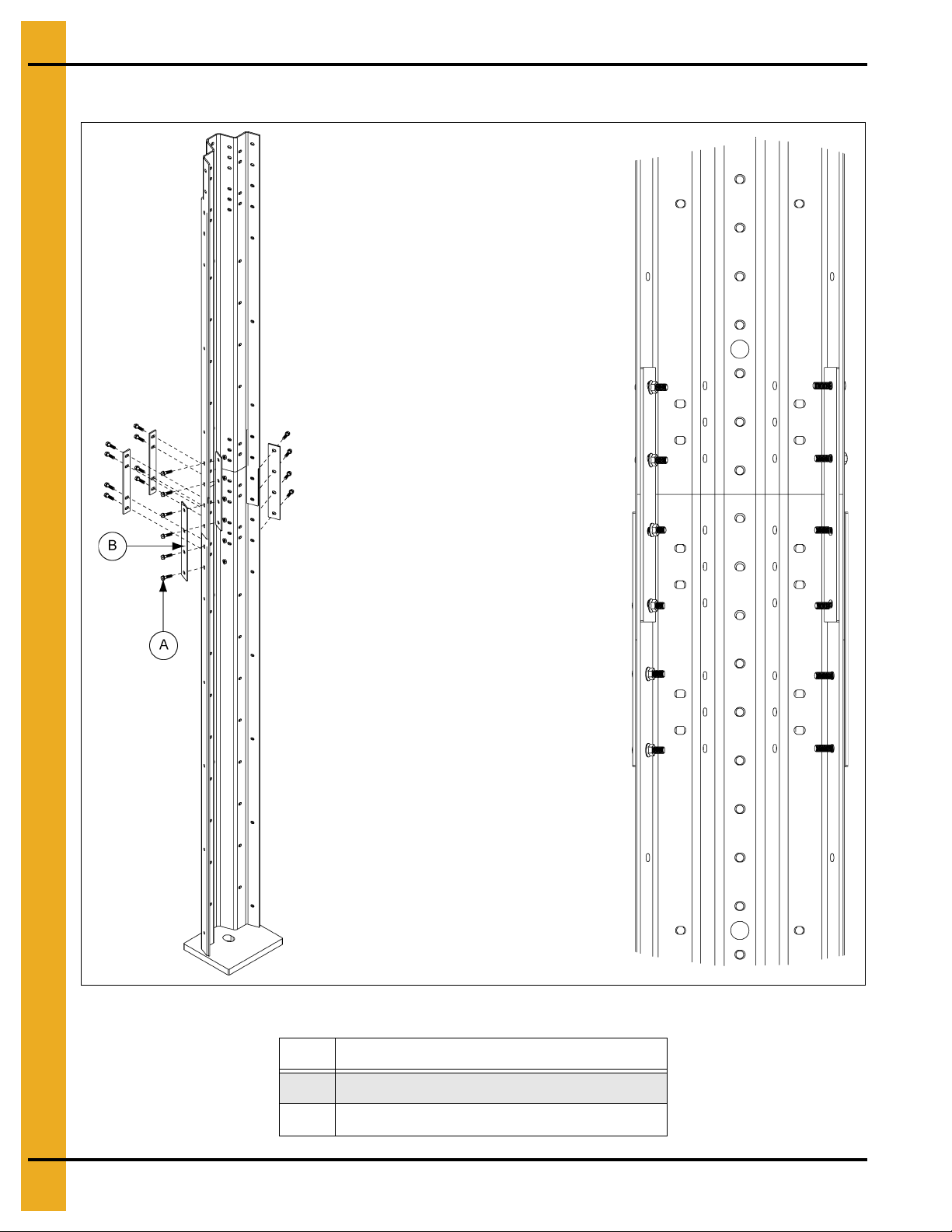
Stiffener to Sidewall Connections 3 Post Tanks
NOTE: Use the dimensioned holes for stiffener to sidewall connections on 3 post tanks.
Figure 9L
Ref # Description
A Horizontal Seam Clearance Holes
B 2 Ring Offset Stiffener (The same hole locations are used
for 14 gauge and 15 gauge 2 ring stiffener (SS-7065).)
C 2 Ring Standard Stiffener
NOTE: Some locations in the lower regions of the tank utilize close punched sheets where the stiffener
will attach more frequently.
PNEG-1000 2.66" Commercial Tank Stiffener and Sidewall 47
9. Stiffener Instruction (Inside Stiffened)
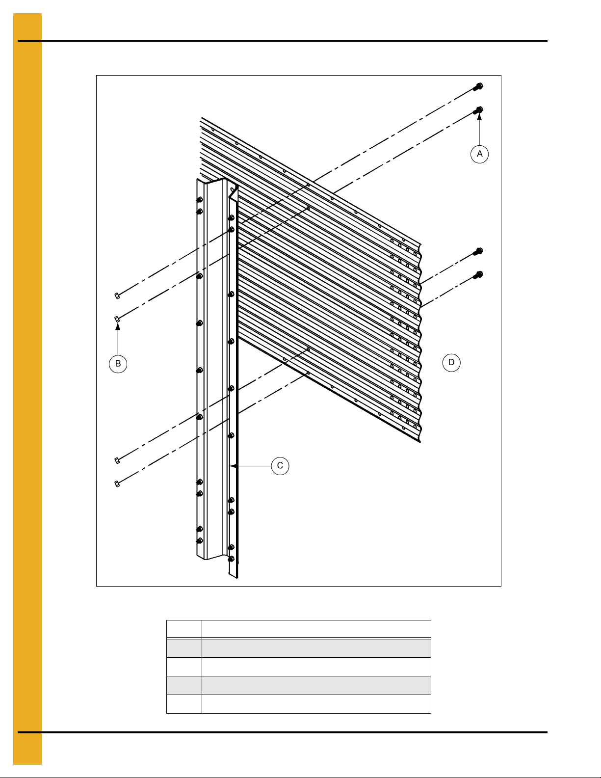
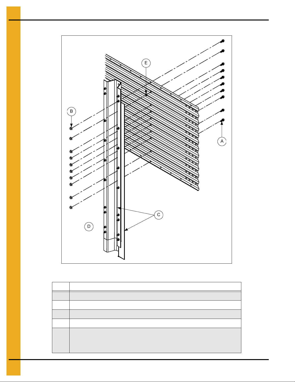
Non-Laminated Stiffener to Sidewall Det a il
Figure 9M Inside Stiffened Non-Laminated Stiffener to Sidewall Detail
Ref # Description
A 3/8" Bin Bolt with a Steel Backed Neoprene Washer
B 3/8" Flange Nut (S-456)
C Non-Laminated Stiffener
D Outside of Bin
48 PNEG-1000 2.66" Commercial Tank Stiffener and Sidewall

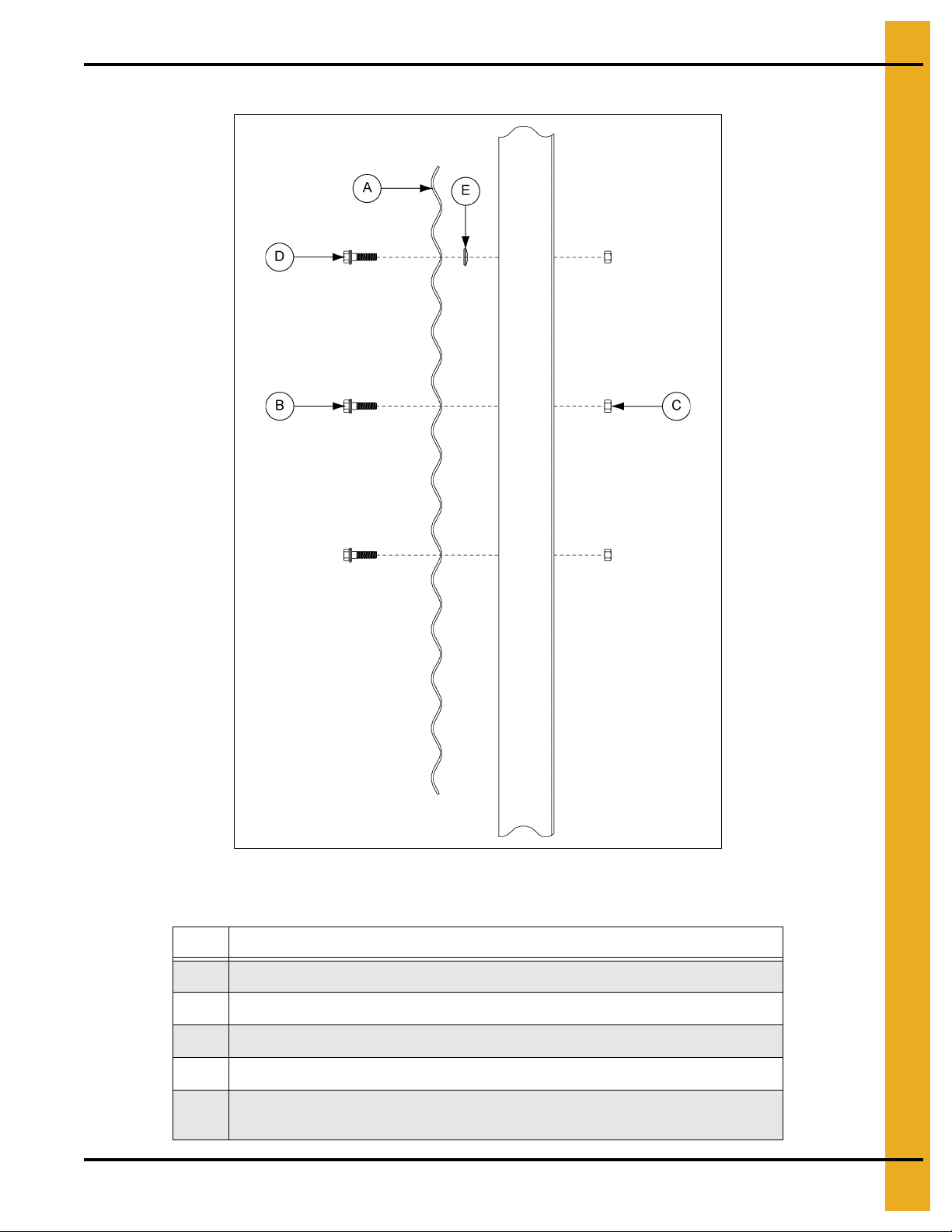
Laminated Stiffener to Sidewall Detail
9. Stiffener Instruction (Inside Stiffened)
Figure 9N Inside Stiffened Laminated Stiffener to Sidewall Detail (11 Gauge Laminated Only)
Ref # Description
A 3/8" Bin Bolt with a Steel Backed Neoprene Washer
B 3/8" Flange Nut (S-9373)
C Two (2) Laminated Stiffeners
D Outside of Bin
PNEG-1000 2.66" Commercial Tank Stiffener and Sidewall 49

9. Stiffener Instruction (Inside Stiffened)
Laminated Stiffener to Sidewall Detail (Continued)
Figure 9O Inside Stiffened Lam inated Stiffener to Sidewall Detail (10 Gauge Laminated and Thicker Only)
Ref # Description
A 3/8" Bin Bolt with a Steel Backed Neoprene Washer
B 3/8" Flange Nut (S-9373)
C Two (2) Laminated Stiffeners
D Outside of Bin
50 PNEG-1000 2.66" Commercial Tank Stiffener and Sidewall

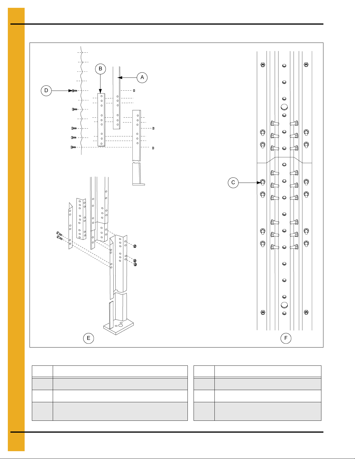
10. Stiffener Assembly (Inside Only)
2 Stiffeners per Sidewall Sheet
Commercial Stiffener Starting Location - 36' Diameter and Smaller
2.66'' Corrugation Inside Stiffener Only
For sidewall to stiffener connections, use 3/8" x 1" bin bolt except horizontal seam. 19 Gauge and
20 gauge sidewall sheet will bolt four (4) locations per sheet. 18 Gauge will bolt at eight (8) locations per
sheet. 17 Gauge and thicker sidewalls will bolt every 2.66".
NOTE: Splice plate and laminated stiffener to sidewall connections use 3/8" x 1-1/2" bin bolts.
Offset joints and 8 gauge splice plated joints use 3/8" x 1" hex flanged head bolts. All other stiffener
joints use 3/8" x 1-1/2" hex flanged head bolts. Flanged nuts are used on the nut side of all stiffened joint
connections. (See Figure 10A.)
Figure 10A
Ref # Description Ref # Description
A Horizontal Seam D Odd Ring Bins
B 1 Ring Offset Stiffener (SS-7064)
C 2 Ring Offset Stiffener (SS-7065 or SS-6982)
PNEG-1000 2.66" Commercial Tank Stiffener and Sidewall 51
E Even Ring Bins

10. Stiffener Assembly (Inside Only)
3 Stiffeners per Sidewall Sheet
Commercial Stiffener Starting Location - 36' Diameter and Smaller
2.66'' Corrugation Inside Stiffener Only
NOTE: Certain tanks may be stiffened to the eave. Refer to the tank gauge layout sheet to determine if
this is the case for the bin.
For sidewall to stiffener connections, use 3/8" x 1" bin bolts except on horizontal seam. Stiffener will
bolt every 8".
NOTE: Splice plate and laminated stiffener to sidewall connections use 3/8" x 1-1/2" bin bolts.
Offset joints and 8 gauge splice plated joints use 3/8" x 1" hex flanged head bolts. All other stiffener joints
use 3/8" x 1-1/2" hex flanged head bolts. Flanged nuts are used on the nut side of all stiffened joint
connections. (See Figure 10B.)
Figure 10B
Ref # Description Ref # Description
A Horizontal Seam D Odd Ring Bins
B 1 Ring Offset Stiffener (SS-7064)
C 2 Ring Offset Stiffener (SS-7065 or SS-6982)
52 PNEG-1000 2.66" Commercial Tank Stiffener and Sidewall
E Even Ring Bins

10. Stiffener Assembly (Inside Only)
3 Stiffeners per Sidewall Sheet (Continued)
Commercial Stiffener Starting Location - 42' Diameter to 105' Diameter
2.66'' Corrugation Inside Stiffener Only
NOTE: Certain tanks may be stiffened to the eave. Refer to the tank gauge layout sheet to determine if
this is the case for the bin.
For sidewall to stiffener connections, use 3/8" x 1" bin bolts except horizontal seam. Stiffener will bolt
every 8".
NOTE: Splice plate and laminated stiffener to sidewall connections use 3/8" x 1-1/2" bin bolts.
Offset joints and 8 gauge splice plated joints use 3/8" x 1" hex flanged head bolts. All other stiffener
joints use 3/8" x 1-1/2" hex flanged head bolts. Flanged nuts are used on the nut side of all stiffened joint
connections. (See Figure 10C.)
Figure 10C
Ref # Description Ref # Description
A Horizontal Seam D Odd Ring Bins
B 1 Ring Offset Stiffener (SS-7064)
C Top Stiffener (One per Sidewall Sheet) (SS-7066)
PNEG-1000 2.66" Commercial Tank Stiffener and Sidewall 53
E Even Ring Bins

10. Stiffener Assembly (Inside Only)
Roof Stiffener Detail
42' Through 60' Standard Roof Stiffener Detail
Ref # Description
A
B Upper Roof Shim (CRP-5350)
C Roof Beam Stiffener (One Per Sidewall Sheet)
Top Stiffener 42' and Larger
(One Per Sidewall Sheet) (SS-7066)
Figure 10D 2.66'' Corrugation Inside Stiffener Only
72' Through 105' Diameter Roof Stiffener Detail 60' Diameter 10000 Lbs.
Peak Load Stiffener Detail
Ref # Description
Top Stiffener 42' and Larger
A
(One Per Sidewall Sheet) (SS-7066)
B Upper Roof Shim (CRP-5350)
C Roof Beam Stiffener (One Per Sidewall Sheet)
D Roof Stiffener Shim Plate (CRP-5336)
Figure 10E 2.66'' Corrugation Inside Stiffener Only
NOTE: The standard 10000 lbs. peak load roof stiffener to sidewall attachment is shown in Figure 10E.
The 20000 lbs. peak load roofs have special attachment details included with the roof instructions
for those roofs.
54 PNEG-1000 2.66" Commercial Tank Stiffener and Sidewall

Wind Ring Assembly
10. Stiffener Assembly (Inside Only)
Ref # Description
A 3/8" x 1" Flanged Head Bolts
B 3/8" Flange Nuts
C Wind Ring Coupler
D C-Clamp (SS-7248)
Figure 10F
1.To connect wind ring pipe to the stiffeners, attach with 3/8" x 1" bolts through the flange of the
stiffener. In some cases, field drilling of wind ring locations may be required.
2. Attach wind ring pipe section to stiffener using two (2) 3/8" x 6" (SS-7248) wind ring clamps.
3. Place pipes end-to-end without overlapping. Fasten together using two (2) wind ring couplers and
six (6) 3/8" x 1" flanged head bolts with flanged nuts. Couplers should be centered on the seam
of pipes.
Wind rings must be installed in relation to the ladder rungs as shown here, to ensure
compliance with O.S.H.A., regulations. (See Figure 10G.)
Ref # Description
E 1-1/2" Minimum
F 4-1/2" Minimum
Figure 10G
PNEG-1000 2.66" Commercial Tank Stiffener and Sidewall 55

NOTES
56 PNEG-1000 2.66" Commercial Tank Stiffener and Sidewall

2.66" Commercial Tank
Stiffener Instructions
Outside Stiffened Only
®
PNEG-1000 2.66" Commercial Tank Stiffener and Sidewall 57
11. Stiffener Instruction (Outside Stiffened)
2.66 Commercial Tank Stiffener Instructions Outside Stiffened Only
Universal Stiffener and Splice Hardware
Stiffeners Splicing Systems
12 Gauge to 12 Gauge
and Thinner
12 Gauge to 11 Gauge
through
8 Gauge to 5 Gauge, 6 Gauge
5 Gauge, 6 Gauge to 5 Gauge, 6 Gauge
5 Gauge to Laminated, Laminated to Laminated,
Laminated to Laminated Enhanced/Universal
Laminated Enhanced/Universal to Laminated Enhanced/Universal
Laminated Enhanced/Universal to Laminated Enhanced/Enhanced
Laminated Enhanced/Enhanced to
Laminated Enhanced/Enhanced
Splice Hardware Usage
(Not Including Sidewall to Splice Bolts)
Use SS-6966 or SS-7427 Splice 2 per Joint
Use SS-6966 or SS-7427 Splice 2 per Joint
Use SS-6966 or SS-7427 Splice 2 per Joint
Offset/Lapped Stiffener
No Separate Splices Plate
Use SS-7053 Splice
Color Code: Y ellow
Use SS-7053 Splice
Color Code: Y ellow
Use SS-7398 Splice 2 per Joint
Use SS-7398 Splice 4 per Joint
Stiffeners Splicing Systems Hardware Part # Description Qty
14 Gauge and 15 Gauge Offset Stiffener Joint
12 Gauge and 13 Gauge Offset Stiffener Joint
10 Gauge and 11 Gauge
8 Gauge and 9 Gauge
5 Gauge and 6 Gauge
Laminated
Laminated to Laminated Enhanced
Laminated Enhanced
SS-7053
Stiffener Joint
SS-7053
Stiffener Joint
SS-7053
Stiffener Joint
SS-6966 or SS-7427
Stiffener Joint
SS-6966 or SS-7427
and SS-7398
Stiffener Joint
SS-6966 or SS-7427
and SS-7398
Stiffener Joint
Stiffener to Sidewall Hardware Usage
Splicing Systems Hardware Part # Description
Stiffener to Sidewall
SS-7053
Splice to Sidewall
Laminated Stiffener to Sidewall
Laminated Enhanced Stiffener
to Sidewall
S-7927 3/8" x 1" 8
S-9373 3/8" Flange Nuts 8
S-7927 3/8" x 1" 10
S-9373 3/8" Flange Nuts 10
S-7927 3/8" x 1" 16
S-9373 3/8" Flange Nuts 16
S-7927 3/8" x 1" 20
S-9373 3/8" Flange Nuts 20
S-7928 3/8" x 1-1/2" 20
S-9373 3/8" Flange Nuts 20
S-7928 3/8" x 1-1/2" 30
S-9373 3/8" Flange Nuts 30
S-7928 3/8" x 1-1/2" 38
S-9373 3/8" Flange Nuts 38
S-7928 3/8" x 1-1/2" 42
S-9373 3/8" Flange Nuts 42
S-455 3/8" x 1"
S-456 3/8" Nuts
S-5060 3/8" x 1-1/2"
S-456 3/8" Nuts
S-5060 3/8" x 1-1/2"
S-9373 3/8" Flange Nuts
S-5060 3/8" x 1-1/2"
S-9373 3/8" Flange Nuts
58 PNEG-1000 2.66" Commercial Tank Stiffener and Sidewall
11. Stiffener Instruction (Outside Stiffened)
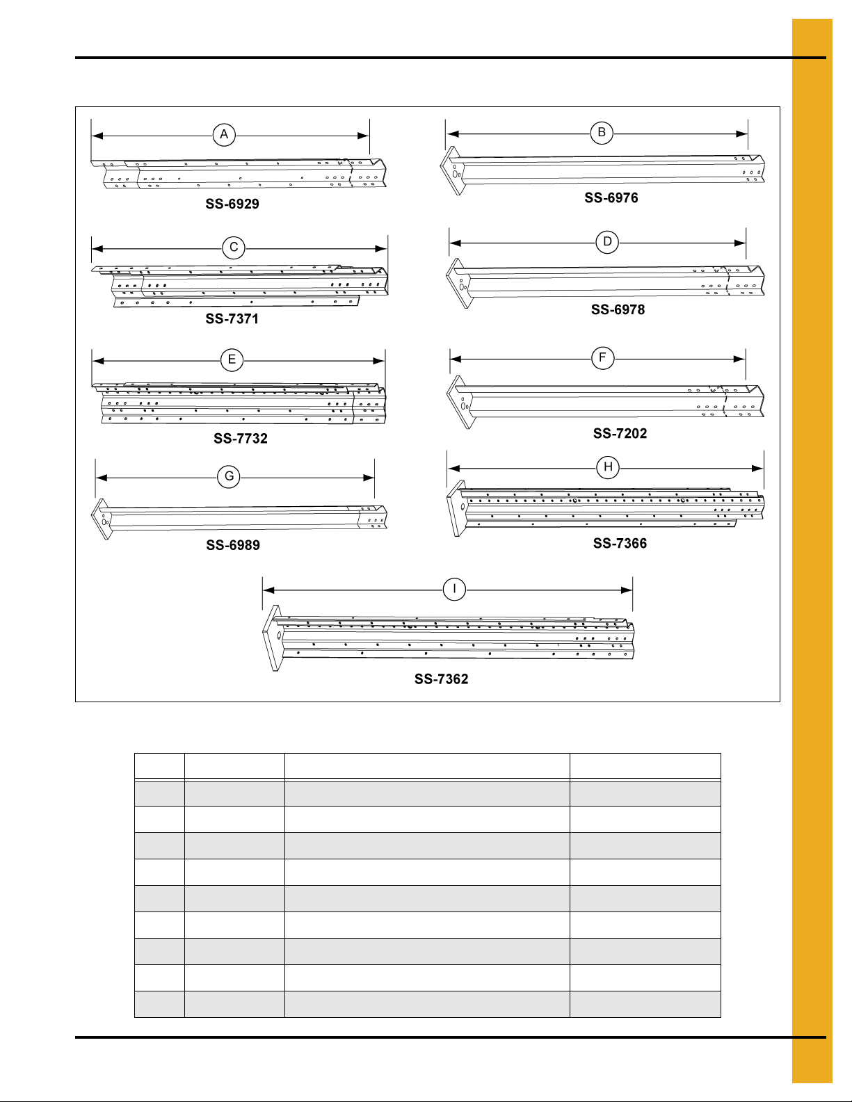
Commercial Stiffeners for 2.66'' Corrugation
Figure 11A
Ref # Part # Description Length
A SS-6929 2 Ring Laminated Stiffener 71.906'' (182.642 cm)
B SS-6976 Base Stiffener 80.094'' (203.438 cm)
C SS-7371 5E+5U Enhanced Laminated 2 Ring Stiffener 71.938" (182.723 cm)
D SS-6978 5+10 and 5+8 Laminated Base Weldment 88.094'' (223.758 cm)
E SS-7372 5E+5E Enhanced Laminated 2 Ring Stiffener 71.938" (182.723 cm)
F SS-7202 5+5 Laminated Base Weldment 87.719'' (222.806 cm)
G SS-6989 Offset Base Stiffener 87-1/8'' (180.260 cm)
H SS-7366 5E+5 Laminated Enhanced Base Weldment 88.844" (225.664 cm)
I SS-7362 5E+5E Laminated Enhanced Base Weldment 88.844" (225.664 cm)
PNEG-1000 2.66" Commercial Tank Stiffener and Sidewall 59

11. Stiffener Instruction (Outside Stiffened)
4" Typical
Commercial Stiffeners for 2.66'' Corrugation (Continued)
Figure 11B
Ref # Part # Description Length
A SS-7065 14 Gauge and 15 Gauge 2 Ring Stiffener 70.969" (180.260 cm)
B SS-6982 12 Gauge and 13 Gauge 2 Ring Stiffener 70.969" (180.260 cm)
C SS-7083 10 Gauge and 11 Gauge 2 Ring Stiffener 63.938" (162.401 cm)
D SS-6923 5 Gauge, 6 Gauge, 8 Gauge and 9 Gauge 2 Ring Stiffener 63.938" (162.401 cm)
E SS-7064 Offset 1 Ring Stiffener 38.969" (98.981 cm)
F SS-7066 1 Ring Top 12.469'' (31.671 cm)
G SS-7053 8 Gauge Splice 14'' (35.56 cm)
H SS-6966 or Laminated Back Plate Splice 22'' (55.88 cm)
H SS-7427 Laminated Back Plate Splice 11-3/4" (29.845 cm)
I SS-7398 Enhanced Back Plate Splice 14" (35.56 cm)
60 PNEG-1000 2.66" Commercial Tank Stiffener and Sidewall

11. Stiffener Instruction (Outside Stiffened)
2.66'' Corrugation Commercial Stiffeners Splice Details
When installing bottom stiffeners, you may find that in some cases the stiffener with base plate attached
will not rest on the foundation (due to unlevel foundation, etc.). Shim plates have been furnished and
should be used to fill opening between base plate and concrete.
IMPORTANT: If shim plates are not used where required, the downward pressure of the stiffeners will not
be transferred directly to the foundation and bin failure could result.
NOTE: Some colors are different than those used for sidewall sheets.
* NOTE: Only Orange on 1 ring stiffener.
Stiffener Color Code Chart
Stiffener Gauge Color Code
15 Red/Orange *
14 Green/Orange *
13 Dark Blue
12 Black
11 Pink
10 Light Blue
9 Purple
8Yellow
6 White
5 Fluorescent Green
5+12 Gold/Black
5+10 Gold/Light Blue
5+8 Gold/Yellow
5+5 Gold/Fluorescent Green
5E+5U Ochre/Gold/White
5E+5E Ochre/Gold/White/Brown
PNEG-1000 2.66" Commercial Tank Stiffener and Sidewall 61
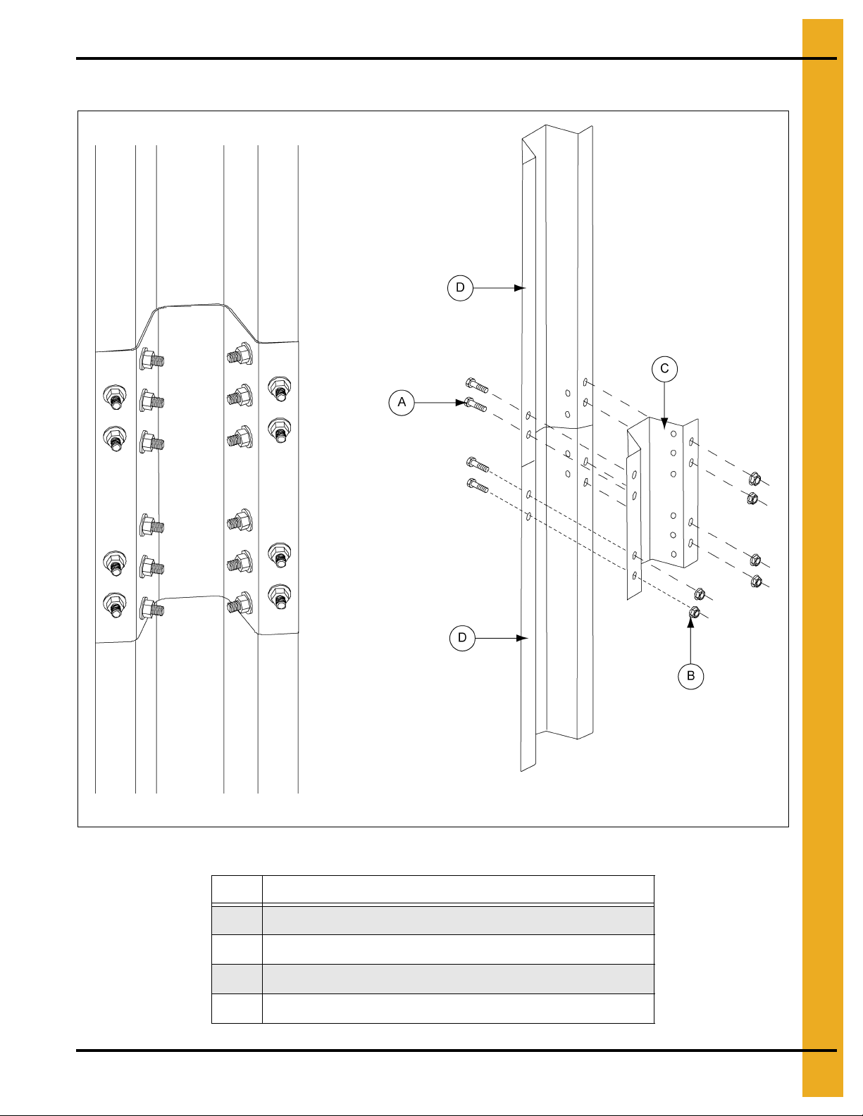
11. Stiffener Instruction (Outside Stiffened)
2.66'' Corrugation Commercial Stiffeners Splice Details (Continued)
Figure 11C
Ref # Description
A Standar d Offset Stiffener
B 3/8" Diameter Hex Flanged Head Bolt (No Sealing Washer)
C 3/8" Flange Nut
D Splice Plate 8 Gauge (SS-7053)
E 2 Ring Standard Stiffener
F Offset Joint Connection Detail
G Base Stiffener (SS-6976)
H Splice Plate Joint Detail (Non-Offset Joints)
I Splice Plate Joint (Top View)
62 PNEG-1000 2.66" Commercial Tank Stiffener and Sidewall
11. Stiffener Instruction (Outside Stiffened)
2.66'' Corrugation Commercial Stiffeners Splice Details (Continued)
Figure 11D
Ref # Description
A Bolt hole not used in 14 gauge and 15 gauge. Do not drill.
B 14 Gauge and 15 Gauge to 14 Gauge and 15 Gauge Offset Connection Detail
C 14 Gauge and 15 Gauge to 13 Gauge and 12 Gauge Offset Connection Detail
PNEG-1000 2.66" Commercial Tank Stiffener and Sidewall 63
11. Stiffener Instruction (Outside Stiffened)
See Page 58 for usage chart.
2.66'' Corrugation Commercial Stiffeners Splice Details (Continued)
Figure 11E 10 Gauge and 11 Gauge Bearing Splice
Ref # Description
A 3/8" Diameter Hex Flanged Head Bolt (No Sealing Washer)
B 3/8" Flange Nut
C Splice Plate 8 Gauge (SS-7053)
D 10 Gauge or 11 Gauge Standard Stiffener
E Bolt holes in splice plate not used. Do not drill.
64 PNEG-1000 2.66" Commercial Tank Stiffener and Sidewall

11. Stiffener Instruction (Outside Stiffened)
See Page 58 for usage chart.
NOTE: Install bolts in all bolt hole locations on stiffener splices.
2.66'' Corrugation Commercial Stiffeners Splice Details (Continued)
Figure 11F 5 Gauge, 6 Gauge, 8 Gauge and 9 Gauge Bearing Splice
Ref # Description
A 3/8" Diameter Hex Flanged Head Bolt (No Sealing Washer)
B 3/8" Flange Nut
C Sp lice Plate 8 Gauge (SS-7053)
D 5 Gauge, 6 Gauge, 8 Gauge and 9 Gauge Standard Stiffener
PNEG-1000 2.66" Commercial Tank Stiffener and Sidewall 65
11. Stiffener Instruction (Outside Stiffened)
NOTE: Install bolts in all bolt hole
locations on stiffener splices.
Laminated Stiffener Splice 2.66" Corrugation
Figure 11G
Ref # Description Ref # Description
A Laminated Stiffener Assembly (SS-6929) D Use 3/8" x 1-1/2" Bin Bolt and 3/8" Hex Nut
B Back Plate Splice (Two (2) per Connection) (SS-6966)
C 3/8" x 1-1/2" Flange Bolts and 3/8" Flange Nuts (30) F
E Stiffener Detail for SS-6929
Bolting Detail for Laminated to
Laminated Stiffener Connection
66 PNEG-1000 2.66" Commercial Tank Stiffener and Sidewall

11. Stiffener Instruction (Outside Stiffened)
NOTE: Install bolts in all bolt hole
locations on stiffener splices.
Laminated Stiffener Splice 2.66" Corrugation (Continued)
Ref # Description Ref # Description
A Laminated Stiffener Assembly (SS-6929) E Laminated Stiffener Splice (SS-7427)
B 3/8" x 1-1/2" Flange Bolts and 3/8" Flange Nuts (30)
C Use 3/8" x 1-1/2" Bin Bolt and 3/8" Hex Nut G
D Bolting Detail for Laminated to Laminated Stiffener Connection
PNEG-1000 2.66" Commercial Tank Stiffener and Sidewall 67
Figure 11H
Use 3/8" x 1-1/2" Flange Bolt and
F
3/8" Flange Nut
Special Laminated Stiffener Splice Detail
(SS-7427 substituted for SS-6966)

11. Stiffener Instruction (Outside Stiffened)
NOTE: Install bolts in all bolt hole
locations on stiffener splices.
Laminated to Universal Stiffener Splice 2.66" Corrugation
Figure 11I Bolting Detail for Laminated to Universal Stiffener Connection
Ref # Description
A 3/8" x 1-1/2" Flange Bolts and 3/8" Flange Nuts (20)
68 PNEG-1000 2.66" Commercial Tank Stiffener and Sidewall

11. Stiffener Instruction (Outside Stiffened)
NOTE: Laminated stiffener splice is used in the
same way as non-enhanced laminated stiffeners.
Laminated to Universal Stiffener Splice 2.66" Corrugation (Continued)
Figure 11J Laminated Enhanced/Universal to Laminated Enhanced Universal and
Laminated Enhanced/Enhanced to Laminated Enhanced/Universal Stiffener Splice 2.66" Corrugation
PNEG-1000 2.66" Commercial Tank Stiffener and Sidewall 69
Ref # Description
A 3/8" x 1-1/2" Flange Bolt
B Enhanced Stiffener Splice Two (2) per Connection
11. Stiffener Instruction (Outside Stiffened)
NOTE: Laminated stiffener splice is used in the
same way as non-enhanced laminated stiffeners.
Laminated to Universal Stiffener Splice 2.66" Corrugation (Continued)
Figure 11K Enhanced/Enhanced to Enhanced/Enhanced Stiffener Splice 2.66" Corrugation
Ref # Description
A 3/8" x 1-1/2" Flange Bolt
B Enhanced Stiffener Splice Four (4) per Connection
70 PNEG-1000 2.66" Commercial Tank Stiffener and Sidewall

11. Stiffener Instruction (Outside Stiffened)
Stiffener to Sidewall Connections 3 Post Tanks
NOTE: Use the dimensioned holes for stiffener to sidewall connections on 3 post tanks.
Figure 11L
Ref # Description
A Horizontal Seam Clearance Holes
B 2 Ring Offset Stiffener (The same hole locations are used
for 14 gauge and 15 gauge 2 ring stiffener (SS-7065).)
C 2 Ring Standard Stiffener
NOTE: Some locations in the lower regions of the tank utilize close punched sheets where the stiffener
will attach more frequently.
PNEG-1000 2.66" Commercial Tank Stiffener and Sidewall 71

11. Stiffener Instruction (Outside Stiffened)
Non-Laminated Stiffener to Sidewall Det a il
Figure 11M Outside Stiffened Non-Laminated Stiffener to Sidewall Detail
Ref # Description
A 3/8" Bin Bolt with a Steel Backed Neoprene Washer
B 3/8" Flange Nut (S-456)
C Non-Laminated Stiffener
D Outside of Bin
72 PNEG-1000 2.66" Commercial Tank Stiffener and Sidewall

Laminated Stiffener to Sidewall Detail
11. Stiffener Instruction (Outside Stiffened)
Figure 11N Outside Stiffened Laminated S tiffener to Sidewall Detail (11 Gauge Laminated Only)
Ref # Description
A 3/8" Bin Bolt with a Steel Backed Neoprene Washer
B 3/8" Flange Nut (S-9373)
C Two (2) Laminated Stiffeners
D Outside of Bin
PNEG-1000 2.66" Commercial Tank Stiffener and Sidewall 73
11. Stiffener Instruction (Outside Stiffened)
Laminated Stiffener to Sidewall Detail (Continued)
Figure 11O Outside Stiffened Laminated Stiffener to Sidewall Detail (10 Gauge Laminated and Thicker Only)
Ref # Description
A 3/8" Bin Bolt with a Steel Backed Neoprene Washer
B 3/8" Flange Nut (S-9373)
C Two (2) Laminated Stiffeners
D Outside of Bin
Place a sealing washer (S-9467) between the stiffener and sidewall sheet on the first
stiffener to sidewall bolt down from the horizontal seam (close punched laminated,
E
10 gauge and thicker only). Placing a small amount of tube caulk on the washer placing
on the sidewall is a aid to inst al l ation.
74 PNEG-1000 2.66" Commercial Tank Stiffener and Sidewall
11. Stiffener Instruction (Outside Stiffened)
Special Detail for 10 Gauge and Thicker Laminated Sidewall
Figure 11P Outside Stiffened Laminated Stiffener to Sidewall Detail
(10 Gauge Laminated Sidewall or Thicker Only)
Ref # Description
A Horizontal Seam
B 3/8" x 1-1/2" Bolt (S-5060)
C 3/8" Flange nut (S-9373) if laminated stiffener.
D NOTE: Use of a longer 2" bolt (S-9445) may be necessary for this bolt.
Sealing washer (S-9467) installed at first sidewall to stiffener connection down from
E
the horizontal seam only. Install with sealing material against the sidewall sheet.
PNEG-1000 2.66" Commercial Tank Stiffener and Sidewall 75

12. Stiffener Assembly (Outside Only)
2 Stiffeners per Sidewall Sheet
Commercial Stiffener Starting Location - 36' Diameter and Smaller
2.66'' Corrugation Outside Stiffener Only
NOTE: Certain tanks may be stiffened to the eave. Refer to the tank gauge layout sheet to determine if
this is the case for the bin.
For sidewall to stiffener connections, use 3/8" x 1" bin bolt except horizontal seam. 19 Gauge and
20 gauge sidewall sheet will bolt four (4) locations per sh eet. 1 8 Gauge will bolt at eight (8) locations per
sheet. 17 Gauge and thicker sidewalls will bolt every 2.66".
NOTE: Splice plate and laminated stiffener to sidewall connections use 3/8" x 1-1/2" bin bolts.
Offset joints and 8 gauge splice plated joints use 3/8" x 1" hex flanged head bolts. All other stiffener
joints use 3/8" x 1-1/2" hex flanged head bolts. Flanged nuts are used on the nut side of all stiffened joint
connections. (See Figure 12A.)
Figure 12A
Ref # Description Ref # Description
A Horizontal Seam D Odd Ring Bins
B 1 Ring Offset Stiffener (SS-7064)
C 2 Ring Offset Stiffener (SS-7065 or SS-6982)
76 PNEG-1000 2.66" Commercial Tank Stiffener and Sidewall
E Even Ring Bins
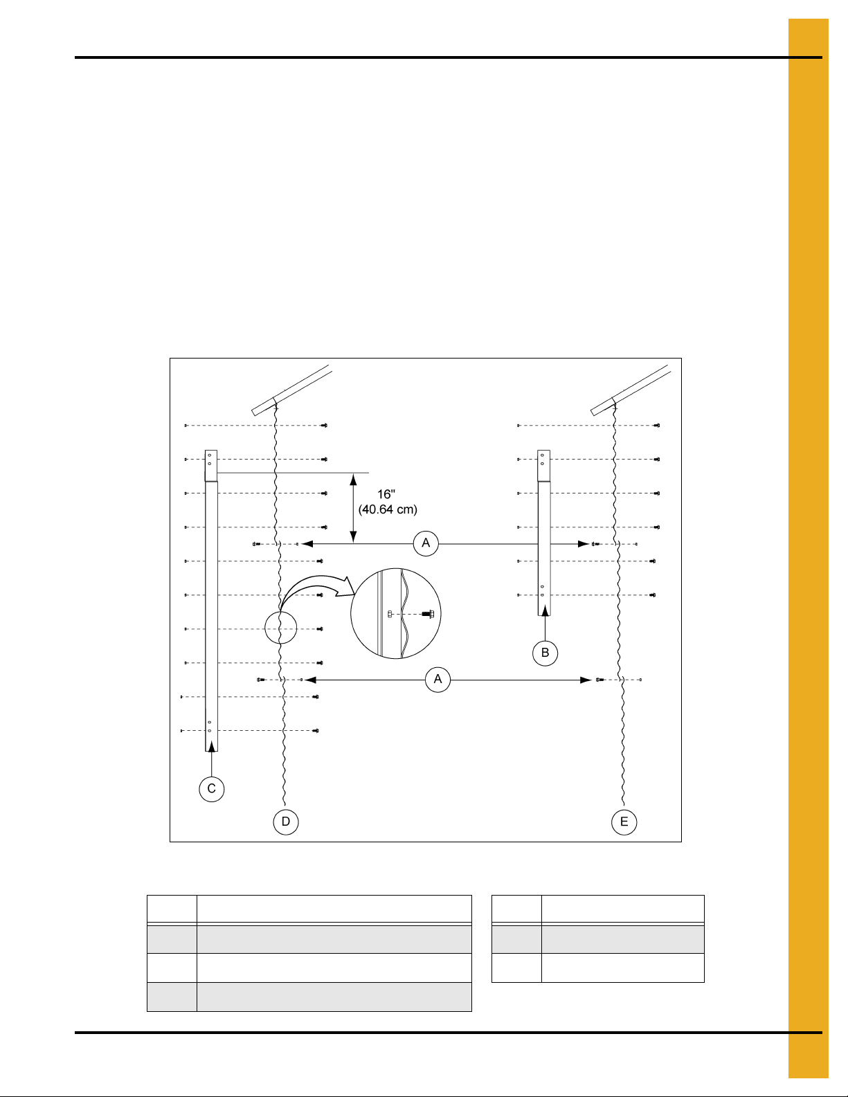
12. Stiffener Assembly (Outside Only)
3 Stiffeners per Sidewall Sheet
Commercial Stiffener Starting Location - 36' Diameter and Smaller
2.66'' Corrugation Outside Stiffener Only
NOTE: Certain tanks may be stiffened to the eave. Refer to the tank gauge layout sheet to determine if
this is the case for the bin.
For sidewall to stiffener connections, use 3/8" x 1" bin bolts except on horizontal seam. Stiffener will bolt
every 8".
NOTE: Splice plate and laminated stiffener to sidewall connections use 3/8" x 1-1/2" bin bolts.
Offset joints and 8 gauge splice plated joints use 3/8" x 1" hex flanged head bolts. All other stiffener joints
use 3/8" x 1-1/2" hex flanged head bolts. Flanged nuts are used on the nut side of all stiffened joint
connections. (See Figure 12B.)
Figure 12B
Ref # Description Ref # Description
A Horizontal Seam D Odd Ring Bins
B 1 Ring Offset Stiffener (SS-7064)
C 2 Ring Offset Stiffener (SS-7065 or SS-6982)
PNEG-1000 2.66" Commercial Tank Stiffener and Sidewall 77
E Even Ring Bins
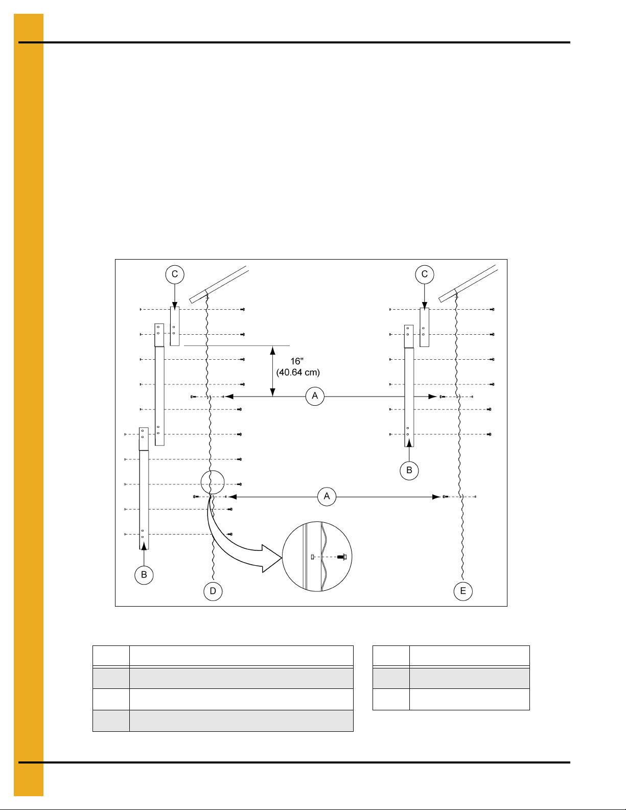
12. Stiffener Assembly (Outside Only)
3 Stiffeners per Sidewall Sheet (Continued)
Commercial Stiffener Starting Location - 42' to 105' Diameter
2.66'' Reverse Corrugation Outside Stiffener Only
NOTE: Certain tanks may be stiffened to the eave. Refer to the tank gauge layout sheet to determine if
this is the case for the bin.
For sidewall to stiffener connections, use 3/8" x 1" bin bolts except horizontal seam. Stiffener will bolt
every 8".
NOTE: Splice plate and laminated stiffener to sidewall connections use 3/8" x 1-1/2" bin bolts.
Offset joints and 8 gauge splice plated joints use 3/8" x 1" hex flanged head bolts. All other stiffener
joints use 3/8" x 1-1/2" hex flanged head bolts. Flanged nuts are used on the nut side of all stiffened joint
connections. (See Figure 12C.)
Figure 12C
Ref # Description Ref # Description
A Horizontal Seam D Odd Ring Bins
B 1 Ring Offset Stiffener (SS-7064)
C Top Stiffener (One Per Sidewall Sheet) (SS-7066)
78 PNEG-1000 2.66" Commercial Tank Stiffener and Sidewall
E Even Ring Bins
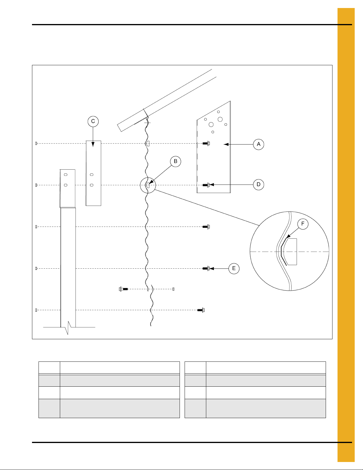
12. Stiffener Assembly (Outside Only)
Roof Stiffener Detail
42' Through 60' Standard Roof Stiffener Detail
Figure 12D 2.66" Corrugation Outside Stiffener Only
Ref # Descrip t ion Ref # Description
A Roof Beam Stiffener (One Per Sidewall Sheet) D 3/8" x 1-1/2" Bolt (S-5060)
B Corrugation Spacer (S-7041)
Top Stiffener 42' and Larger
C
(One Per Sidewall Sheet) (SS-7066)
E 3/8" x 1" Bolt (S-455)
Insert steel backed neoprene between
F
spacer and sidewall.
NOTE: Insert corrugation spacer (S-7041) into corrugation.
PNEG-1000 2.66" Commercial Tank Stiffener and Sidewall 79

12. Stiffener Assembly (Outside Only)
Roof Stiffener Detail (Continued)
72' Through 105' Diameter Roof Stiffener Detail 60' Diameter 10000 Lbs.
Peak Load Roof Stiffener Detail
Figure 12E 2.66" Corrugation Outside Stiffener Only
Ref # Description Ref # Description
A Roof Beam Stiffener (One Per Sidewall Sheet) D 3/8" x 1-1/2" Bolt (S-5060)
B Corrugation Spacer (S-7041)
Top Stiffener 42' and Larger
C
(One Per Sidewall Sheet) (SS-7066)
E 3/8" x 1" Bolt (S-455)
Insert steel backed neoprene between
F
spacer and sidewall.
NOTE: Insert corrugation spacer (S-7041) into corrugation.
NOTE: The standard 10000 lbs. peak load roof stiffener to sidewall attachment is shown in Figure 12E.
The 20000 lbs. peak load roofs have special attachment details included with the roof instructions
for those roofs.
80 PNEG-1000 2.66" Commercial Tank Stiffener and Sidewall
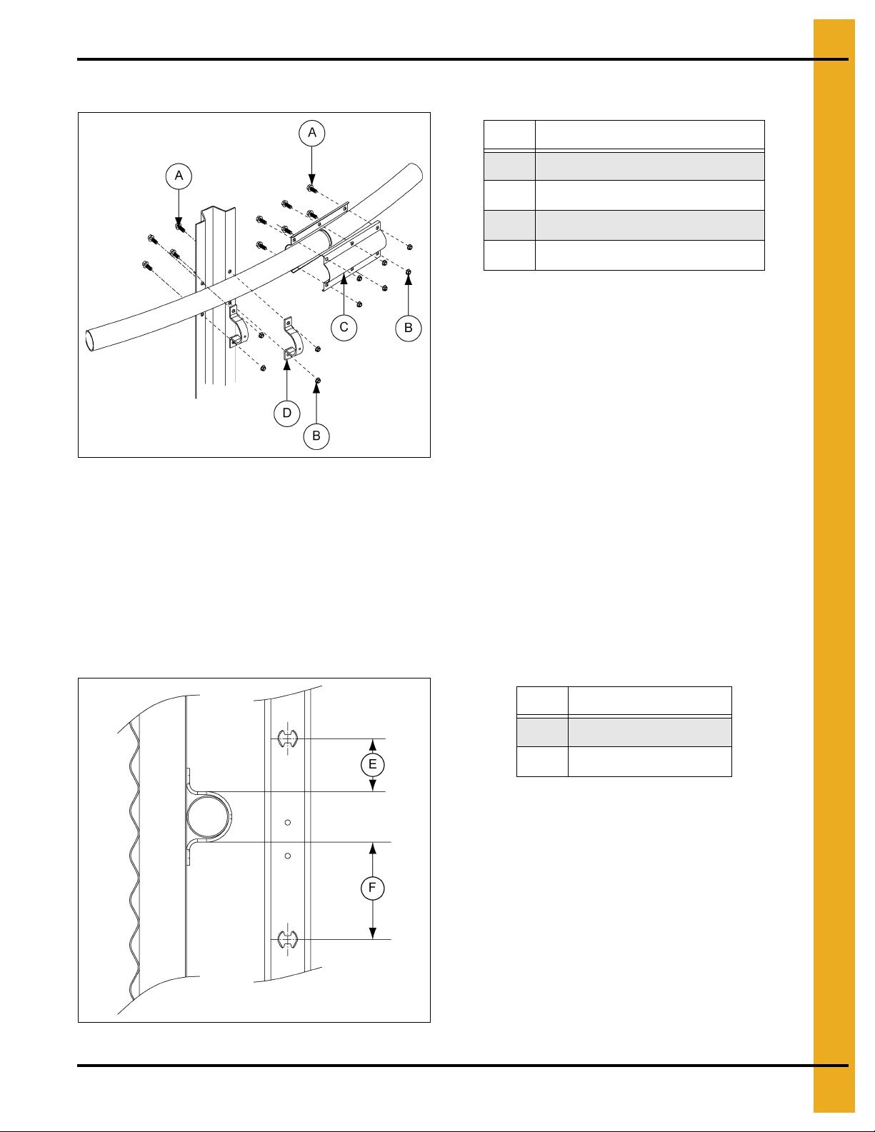
Wind Ring Assembly
12. Stiffener Assembly (Outside Only)
Ref # Description
A 3/8" x 1" Flanged Head Bolts
B 3/8" Flange Nuts
C Wind Ring Coupler
D C-Clamp (SS-7248)
Figure 12F
1.To connect wind ring pipe to the stiffeners, attach with 3/8" x 1" bolts through the flange of the
stiffener. In some cases, field drilling of wind ring locations may be required.
2. Attach wind ring pipe section to stiffener using two (2) 3/8" x 6" (SS-7248) wind ring clamps.
3. Place pipes end-to-end without overlapping. Fasten together using two (2) wind ring couplers and
six (6) 3/8" x 1" flanged head bolts with flanged nuts. Couplers should be centered on the seam
of pipes.
Wind rings must be installed in relation to the ladder rungs as shown here, to ensure
compliance with O.S.H.A., regulations. (See Figure 12G.)
Ref # Description
E 1-1/2" Minimum
F 4-1/2" Minimum
Figure 12G
PNEG-1000 2.66" Commercial Tank Stiffener and Sidewall 81

13. Accessory Instructions
Sidedraw Systems
Installation and Management of Sidedraw Systems
Grain systems designs and manufactures bins to the highest standards, however proper installation
and good usage practices for a commercial flume system are essential, regardless of manufacturer.
The following practices address general usage and installation criteria for such systems.
Sidedraw Installation
1. Side discharge is only permitted in GSI commercial bins when a GSI manufactured sidedraw flume
system has been installed. No corrugated steel bin should be unload ed through the sidewall without
installation of such a system and permission of the manufacturer.
2. Installation of a flume system may require installation of additional wind rings and 1" diameter anchor
bolts. Refer the tank gauge sheet for wind ring placement or contact GSI. Refer the 1" anchor bolt
usage on Page 83.
Installation of multiple systems may require additional wind rings and must be placed a minimum of
90° apart. Installation of multiple systems requires approval of GSI.
3. A sidedraw should not be the only discharge system available. A standard center discharge and
conveyor should be installed.
Sidedraw Management and Usage
1. Sidedraw systems are intended for use with dry flowable grain. Sidedraws are not to be used for
poorly flowing products. This is not unique to GSI bins and flume systems but is a general rule for
such systems.
2. In multiple system installations, only one sidedraw may be used at any one time.
3. Filling should not be occurring at the same time as grain is being withdrawn through the sidedraw
flume system.
4. Prolonged storage of grain in the sloped condition produced by sidedraw discharge may accelerate
differential settlement and result in deformations of the bin/silo. After using the sidedra w system the
sloped grain should be returned to a near level condition by use of the center discharge. Leveling of
the grain should also allow more even consolidation of foundation and fill soils and produce more
even settlement of the bin/silo.
5. If geotechnical investigations or past experience indicate significant foundation level soil variations
or a site propensity toward differential settlement, sidedraw usage may be prohibited or severely
restricted. In this situation the use of a flume system should be reviewed with geotechnical
consultants or the foundation engineer.
82 PNEG-1000 2.66" Commercial Tank Stiffener and Sidewall

1" Anchor Bolts Required with Sidedraw Systems
Used with 2.66" Corrugation Commercial Tanks
Corrugation Tank Diameter Total Number of 1" Anchor Bolts
2.66" 42' 42
2.66" 48' 48
2.66" 54' 54
2.66" 60' 60
2.66" 72' 72
2.66" 75' 75
2.66" 78' 78
2.66" 90' 90
2.66" 105' 105
Use 1" diameter anchor bolts at all of the required stiffener locations.
Wind Ring Installation
Additional Wind Rings Required for 2.66" Commercial Tanks
with Sidedraw Chute Systems (One System Only)
13. Accessory Instructions
Rings
37 - - - - 7 1 7 1 7 1 8 1 8 1 - - - - 37
36 - - - - 6 1 6 1 7 1 7 1 7 2 - - - - 36
35 - - - - 6 1 6 1 6 1 7 1 7 1 7 1 - - 35
34 - - - - 5 1 5 1 6 2 6 2 6 2 6 2 6 2 34
33 - - - - 4 2 4 2 5 2 5 3 5 3 5 3 6 2 33
32 4 1 4 1 4 1 4 1 5 2 5 2 5 2 5 2 5 3 32
31 3 2 3 2 4 1 4 1 4 2 4 2 4 2 4 2 5 3 31
30 3 2 3 2 4 1 4 1 4 1 4 1 4 1 4 2 4 3 30
29 2 1 3 1 3 2 3 2 3 2 3 2 3 2 4 2 4 3 29
28 2 1 2 1 2 2 2 2 2 2 3 2 3 2 3 3 4 3 28
27 1 1 2 1 2 2 2 2 2 2 3 2 3 2 3 3 3 4 27
26 1 1 1 1 2 2 2 2 2 2 2 2 3 2 3 3 3 4 26
25 - 1 1 1 1 2 1 2 2 2 2 2 2 2 3 3 3 4 25
24 - 1 - 1 1 2 1 2 2 2 2 2 2 2 2 3 3 3 24
23 - 1 - 1 1 2 1 2 2 2 2 2 2 2 2 3 2 4 23
22 - 1 - 1 1 2 1 2 2 2 2 2 2 2 2 3 2 3 22
21 - 1 - 1 - 3 1 2 2 2 2 2 2 2 2 3 2 3 21
20 - 1 - 1 - 3 1 2 2 2 2 2 2 2 2 3 2 3 20
19 - 1 - 1 - 3 1 2 1 3 2 2 2 2 2 3 2 3 19
18 - 1 - 1 - 3 1 2 1 3 1 3 2 2 2 3 2 3 18
17 - 1 - 1 - 3 1 2 1 2 1 2 1 2 2 2 2 2 17
16 - 1 - 1 - 3 - 3 1 2 1 2 1 2 1 2 1 2 16
15 - 1 - 1 - 3 - 3 1 2 1 2 1 2 1 1 1 2 15
14 - 1 - 1 - 2 - 2 - 2 - 2 - 2 1 2 1 2 14
13 - 1 - 1 - 1 - 2 - 2 - 2 - 2 - 2 1 1 13
12-----1-2-2-2-2-21112
42' 48' 54' 60' 72' 75' 78' 90' 105'
Std Add Std Add Std Add Std Add Std Add Std Add Std Add Std Add Std Add
Rings
NOTE: Consult the gauge sheet supplied with the tank for complete wind ring quantities and placement
for the specific tank the sidedraw is being installed in.
PNEG-1000 2.66" Commercial Tank Stiffener and Sidewall 83

13. Accessory Instructions
Sidedraw Instructions
2.66'' Sidedraw Instructions - 2 Post (Viewed from Inside of Bin)
Wind Ring Installation
Tanks that use wind rings require 2-3/4" diameter holes passing through the sidedraw chute; with the
center no less than 6" from either end and 4-3/8" from the sidewall. The wind ring must penetrate th rough
the chute and form a complete ring. Do not locate wind ring in 8" space at chute entrance. Field drill
stiffeners for wind ring attachment brackets (if required).
Discharge Tube Installation
1. Use the bottom two (2) holes in the last chute to locate discharge tube 28" below the 7th
horizontal seam. Refer to Figure 13A on Page 85 and Figure 13E on Page 89 for sidewall sheet
hole dimensions.
2. For proper water shed, install plate so upper body sheet overlaps the plate, as shown in Figure 13D
on Page 88 and Figure 13F on Page 90.
3. Use discharge tube assembly as a template, drill all holes 7/16" diameter.
4. Use two (2) beads of caulking to seal discharge plate to body sheets. Use 3/8" bolts and nuts
provided to bolt discharge assembly to body sheets.
Number of Rings in Tank Chute Location Horizontal Starting Location
1. Locate 1st chute in 2nd ring from top.
All
2. Top bolt holes in chute to be located on 2nd corrugation of body sheet.
11, 12, 15, 17, 19, 21 and 23 3. Center chute over vertical seam.
10, 12, 14, 16, 18, 20, 22 and 24 4. Center chute 56-1/4'' from the 1st horizontal seam bolt in the 2nd ring.
84 PNEG-1000 2.66" Commercial Tank Stiffener and Sidewall

13. Accessory Instructions
Sidedraw Instructions (Continued)
2.66'' Sidedraw Instructions - 2 Post (Viewed from Inside of Bin) (Continued)
Figure 13A
Ref # Description
A Stiffener Column
B
7th Sidewall Ring
C
6th Sidewall Ring
D Horizontal Seam
E Field cut discharge hole 1-1/2" radius at corners (3.80 cm)
F Externally stiffened is 1-1/3" higher
G First Chute Location
H Viewing Inside of Typical 24 Ring Bin
NOTE: Unload tubes and support from rack and pinion not provided by GSI.
PNEG-1000 2.66" Commercial Tank Stiffener and Sidewall 85

13. Accessory Instructions
Sidedraw Instructions (Continued)
2.66'' Sidedraw Instructions - 3 Post (Viewed from Inside of Bin)
These instructions for 90' diameter tanks and smaller. See PNEG-972 or PNEG-1343 for 105'
diameter tank sidedraw installation instructions.
Wind Ring Installation
Tanks that use wind rings require 2-3/4" diameter holes passing through the sidedraw chute; with the
center no less than 6" from either end and 4-3/8" from the sidewall. The wind ring must penetrate through
the chute and form a complete ring. Do not locate wind ring in 8" space at chute entrance. Field drill
stiffeners for wind ring attachment brackets (if required).
Discharge Tube Installation
1. Use the bottom two (2) holes in the last chute to locate discharge tube 28" below the 7th horizontal
seam. Refer to Figure 13B on Page 87 and Figure 13E on Page 89 for sidewall sheet hole
dimensions.
2. For proper water shed, install plate so upper body sheet overlaps the plate, as shown in Figure 13D
on Page 88 and Figure 13F on Page 90.
3. Use discharge tube assembly as a template, drill all holes 7/16" diameter.
4. Use two (2) beads of caulking to seal discharge plate to body sheets. Use 3/8" bolts and nuts
provided to bolt discharge assembly to body sheets. For all locations where the sidewall uses
3/8" x 1-1/2" long bolts, use the same bolt to install the discharge tube.
Number of Rings in Tank Chute Location Horizontal Starting Location
1. Locate 1st chute in 2nd ring from top.
All
2. Top bolt holes in chute to be located on 2nd corrugation of body sheet.
11, 14, 17, 20, 23, 26, 29, 32 and 35 3. Center chute 75 inches (left to right) from 1
10, 13, 16, 19, 22, 25, 28, 31, 34 and 37 4. Center chute 37.500 inches (left to right) from 1st hole in 2nd body sheet.
12, 15, 18, 21, 24, 27, 30, 33 and 36 5. Center chute over vertical seam.
st
hole in 2nd body sheet.
86 PNEG-1000 2.66" Commercial Tank Stiffener and Sidewall

13. Accessory Instructions
Sidedraw Instructions (Continued)
2.66'' Sidedraw Instructions - 3 Post (Viewed from Inside of Bin) (Continued)
Figure 13B
Ref # Description
A Stiffener Column
B
7th Sidewall Ring
C
6th Sidewall Ring
D Horizontal Seam
E Field cut discharge hole 1-1/2" radius at corners (3.80 cm)
F Externally stiffened is 1-1/3" higher
G First Chute Location
H Viewing Inside of Ty pical 29 Ring Bin
NOTE: Unload tubes and support from rack and pinion not provided by GSI.
PNEG-1000 2.66" Commercial Tank Stiffener and Sidewall 87

13. Accessory Instructions
Sidedraw Instructions (Continued)
2.66" Sidedraw Instructions - 2 and 3 Post (Internally Stiffened)
Figure 13C
Ref # Description Ref # Description
A Inside of bin F Stiffener
B Chute
C First Horizontal Seam from Eave H 8" Typical (20.32 cm)
D
Starting Location: 2
E Field Drill Sidewall to Match Chute. (7/16" Diameter Holes) J 2-3/4" Diameter (6.99 cm)
nd
Inside Corrugation of the 2nd Ring
G 4" Typical (10.16 cm)
I 6" Diameter (15.24 cm)
Field cutting of chutes is necessary to install the wind rings. Locate wind rings as shown. The wind ring
must be assembled into a complete ring and penetrate through the chute. Field drill stiffeners for
attachment brackets (if required).
Ref # Description
B Chute
K
L Sidedraw Plate
M
N
O
P
Q 28" Typical (71.12 cm)
R 15" Ty pical (38.10 cm)
S 12-3/4" T y p i ca l (32. 39 cm)
th
6
Horizontal Seam from Tank Base
th
6
Ring from Tank Base
8th Ring from Tank Base
th
7
Horizontal Seam from Tank Base
7th Ring from Tank Base
NOTE: Unload tubes and supports from rack and
pinion not provided by GSI.
Figure 13D
88 PNEG-1000 2.66" Commercial Tank Stiffener and Sidewall

13. Accessory Instructions
Sidedraw Instructions (Continued)
2.66" Sidedraw Instructions - 2 and 3 Post (Externally Stiffened)
Figure 13E
Ref # Description Ref # Description
A Stiffener Column E Field Cut Discharge Hole 1-1/2" Radius at Corners (3.80 cm)
B
C
D Horizontal Seam
th
7
Sidewall Ring
6th Sidewall Ring
F Externally Stiffened - 2 Post
G Externally Stiffened - 3 Post
NOTE: Unload tubes and supports from rack and pinion not provided by GSI.
PNEG-1000 2.66" Commercial Tank Stiffener and Sidewall 89
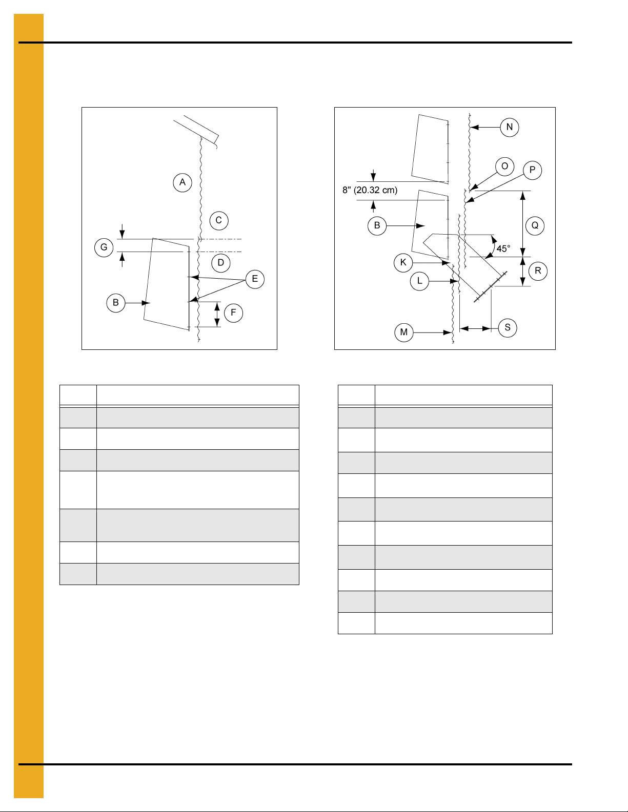
13. Accessory Instructions
Sidedraw Instructions (Continued)
2.66" Sidedraw Instructions - 2 and 3 Post (Externally Stiffened) (Continued)
Figure 13F Externally Stiffened Figure 13G Externally Stiffened
Ref # Description
A Inside of bin
BChute
C First Horizontal Seam from Eave
Starting Location: 2nd Inside Corrugation
D
of the 2
Field Drill Sidewall to Match Chute
E
(7/16" Diameter Holes)
F 8" Typical (20.32 cm)
G 2.677" Typical (6.77 cm)
nd
Ring
Ref # Description
B Chute
K
6th Horizontal Seam from Tank Base
L Sidedraw Plate
M
6th Ring from Tank Base
N
8th Ring from Tank Base
O
P
Q 26.667" Typical (67.73 cm)
R 16.333" Typical (41.49 cm)
S 12-3/4" T y p i ca l (32. 39 cm)
th
7
Horizontal Seam from Tank Base
7th Ring from Tank Base
NOTE: Unload tubes and supports from rack and pinion not provided by GSI. (See Figure 13F.)
NOTE: When installing the discharge weldment, use the same 3/8" bolts as the installation rings vertical
seam. For example, if 3/8" x 1-1/2" bolts were used, utilize that size bolt. (See Figure 13G.)
90 PNEG-1000 2.66" Commercial Tank Stiffener and Sidewall
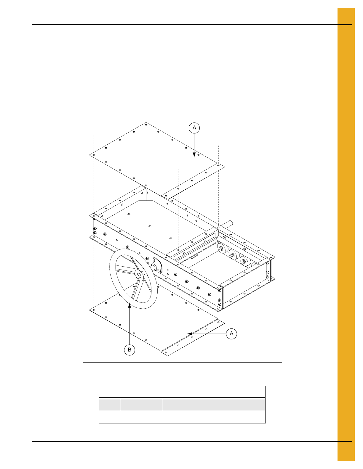
13. Accessory Instructions
Weather Cover Assembly
Weather Cover Assembly Instructions for Roller Valve
1. Install weather cover kit after gate has been installed.
2. Use bead caulking at all seams where weather cover attaches to gate.
3. Use 5/8" x 3/4" bolts and nuts to plug all holes not in use.
4. Use 1/4" self-drillers to seal gate end plate corners. (See Figure 13H.)
Figure 13H
Ref # Part # Description
A CHT-1351 Universal Weather Cover Plate
B Chain Wheel (Typical)
PNEG-1000 2.66" Commercial Tank Stiffener and Sidewall 91

NOTES
92 PNEG-1000 2.66" Commercial Tank Stiffener and Sidewall
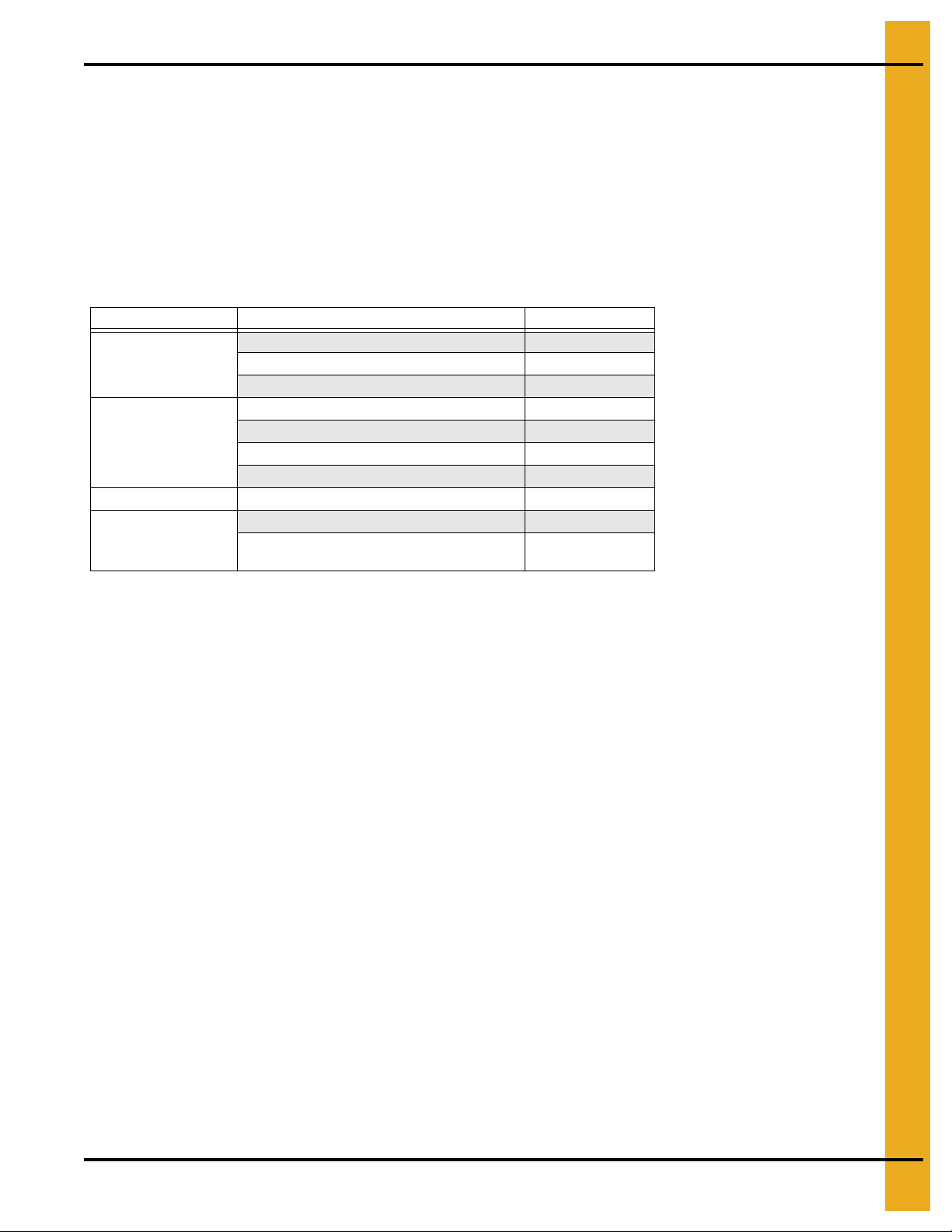
14. Warranty
9101239_1_CR_rev7.DOC (revised July 2009)
GSI Group, LLC Limited Warranty
The GSI Group, LLC (“GSI”) warrants products which it manufactures to be free of defects in materials and workmanship
under normal usage and conditions for a period of 12 months after sale to the original end-user or if a foreign sale,
14 months from arrival at port of discharge, whichever is earlier. The end-user’s sole remedy (and GSI’s only obligation)
is to repair or replace, at GSI’s option and expense, products that in GSI’s judgment, contain a material defect in materials
or workmanship. Expenses incurred by or on behalf of the end-user without prior written authorization from the GSI
Warranty Group shall be the sole responsibility of the end-user.
Warranty Extensions:
The Limited Warranty period is extended for the following products:
Product Warranty Period
Performer Series Direct Drive Fan Motor 3 Years
AP Fans and Flooring
Cumberland
Feeding/Watering
Systems
Grain Systems Grain Bin Structural Design 5 Years
Grain Systems
Farm Fans
Zimmerman
All Fiberglass Housings Lifetime
All Fiberglass Propellers Lifetime
Feeder System Pan Assemblies 5 Years **
Feed Tubes (1-3/4" and 2.00") 10 Years *
Centerless Augers 10 Years *
Watering Nipples 10 Years *
Portable and Tower Dryers 2 Years
Portable and Tower Dryer Frames and
Internal Infrastructure †
5 Years
* Warranty prorated from list price:
0 to 3 years - no cost to end-user
3 to 5 years - end-user pays 25%
5 to 7 years - end-user pays 50%
7 to 10 years - end-user pays 75%
** Warranty prorated from list price:
0 to 3 years - no cost to end-user
3 to 5 years - end-user pays 50%
† Motors, burner components
and moving parts not included.
Portable dryer screens included.
Tower dryer screens not included.
GSI further warrants that the portable and tower dryer frame and basket, excluding all auger and auger drive components,
shall be free from defects in materials for a period of time beginning on the twelfth (12
and continuing until the sixtieth (60
th
) month from the date of purchase (extended warranty period). During the extended
th
) month from the date of purchase
warranty period, GSI will replace the frame or basket components that prove to be defective under normal conditions of
use without charge, excluding the labor, transportation, and/or shipping costs incurred in the performance of this
extended warranty.
Conditions and Limitations:
THERE ARE NO WARRANTIES THAT EXTEND BEYOND THE LIMITED WARRANTY DESCRIPTION SET FORTH
ABOVE. SPECIFICALLY, GSI MAKES NO FURTHER WARRANTY OF ANY KIND, EXPRESS OR IMPLIED,
INCLUDING, WITHOUT LIMITATION, WARRANTIES OF MERCHANTABILITY OR FITNESS FOR A PARTICULAR
PURPOSE OR USE IN CONNECTION WITH: (I) PRODUCT MANUFACTURED OR SOLD BY GSI OR (II) ANY ADVICE,
INSTRUCTION, RECOMMENDATION OR SUGGESTION PROVIDED BY AN AGENT, REPRESENTA TIVE OR
EMPLOYEE OF GSI REGARDING OR RELATED TO THE CONFIGURATION, INSTALLATION, LAYOUT, SUITABILITY
FOR A PARTICULAR PURPOSE, OR DESIGN OF SUCH PRODUCTS.
GSI shall not be liable for any direct, indirect, incidental or consequential damages, including, without limitation, loss of
anticipated profits or benefits. The sole and exclusive remedy is set forth in the Limited Warranty, which shall not exceed
the amount paid for the product purchased. This warranty is not transferable and applies only to the original end-user. GSI
shall have no obligation or responsibility for any representations or warranties made by or on behalf of any dealer, agent
or distributor.
GSI assumes no responsibility for claims resulting from construction defects or unauthorized modifications to products
which it manufactured. Modifications to products not specifically delineated in the manual accompanying the equipment at
initial sale will void the Limited Warranty.
This Limited Warranty shall not extend to products or parts which have been damaged by negligent use, misuse, alteration,
accident or which have been improperly/inadequately maintained. This Limited Warranty extends solely to products
manufactured by GSI.
Prior to installation, the end-user has the responsibility to comply with federal, state and local codes which apply to the
location and installation of products manufactured or sold by GSI.
PNEG-1000 2.66" Commercial Tank Stiffener and Sidewall 93
This equipment shall be installed in accordance with
the current installation codes and applicable
regulations, which should be carefully followed in all
cases. Authorities having jurisdiction should be
consulted before installations are made.
GSI Group
1004 E. Illinois St.
Assumption, IL 62510-0020
Phone: 1-217-226-4421
Fax: 1-217-226-4420
www.gsiag.com
Copyright © 2013 by GSI Group
Printed in the USA
GSI is a worldwide brand of AGCO Corporation.
CN-308615
 Loading...