

Page 1
2003 Top Dry Service School
GSI / Top Dry
Service School
2003
PNEG-1314
1
Page 2

2003 Top Dry Service School
Contents
Safety Pages..........................4
Product Updates...................7
Softwar e Revisions..............1 1
Batch T roubleshooting.......19
Autoflow T roubleshooting..25
Diagnostics..........................32
Warranty.............................40
2
Page 3

2003 Top Dry Service School
3
Page 4
2003 Top Dry Service School
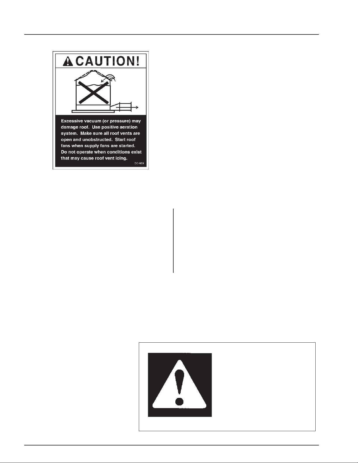
Roof Damage Warning and Disclaimer
GSI DOES NOT WARRANT ANY ROOF DAMAGE
CAUSED BY EXCESSIVE VACUUM OR INTERNAL
PRESSURE FROM F ANS OR OTHER AIR MOVING
SYSTEMS. ADEQUATE VENTILATION AND/OR
"MAKEUP AIR" DEVICES SHOULD BE PROVIDED
FOR ALL POWERED AIR HANDLING SYSTEMS.
GSI DOES NOT RECOMMEND THE USE OF DOWNWARD FLOW SYSTEMS (SUCTION). SEVERE
ROOF DAMAGE CAN RESULT FROM ANY
BLOCKAGE OF AIR PASSAGES. RUNNING F ANS
DURING HIGH HUMIDITY/COLD WEA THER CONDITIONS CAN CAUSE AIR EXHAUST OR INT AKE
PORTS TO FREEZE.
Operating Instructions
The principal concern of the GSI Group, Inc. ("GSI")
is your safety and the safety of others associated
with grain handling equipment. This manual is written to help you understand safe operating procedures, and some of the problems that may be encountered by the operator or other personnel.
The symbol shown is used to call your
attention to instructions concerning your
personal safety. Watch for this symbol; it points out important safety precautions. It means "ATTENTION",
"WARNING", "CAUTION", and
"DANGER". Read the message and
be cautious to the possibility of personal injury or death.
As owner and/or operator, it is your responsibility to know what requirements, hazards and precautions exist, and to inform all personnel associated with the equipment, or who are in the fan area.
A void any alterations to the equipment. Such alterations may produce a very dangerous situation,
where serious injury or death may occur.
Safety Alert Symbol
WARNING! BE ALERT!
Personnel operating or working
around electric fans should read this
manual. This manual must be
delivered with the equipment to its
owner. Failure to read this manual
and its safety instructions is a misuse
of the equipment.
4
Page 5
2003 Top Dry Service School
Grain Systems, Inc.
recommends contacting your
local power company , and
having a representative
survey your installation so
the wiring is compatible with
their system, and adequate
power is supplied to your
unit.
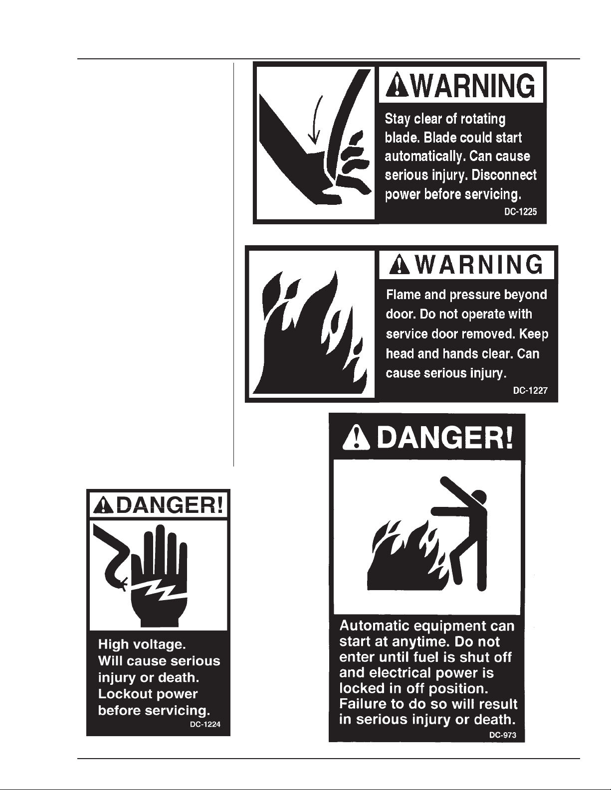
Safety decals should be read
and understood by all people in the
grain handling area. The rotating
blade, fire warning decals and
voltage danger decal must be displayed on the fan can. The bottom right decal should be present
on the inside bin door cover of the
two ring door, 24" porthole door
cover and the roof manway cover.
If a decal is damaged or is
missing contact:
Grain Systems, Inc.
1004 E. Illinois St.
Assumption, IL 62510
217-226-4421
A free replacement will be sent to
you.
5
Page 6

2003 Top Dry Service School
READ THESE INSTRUCTIONS
BEFORE OPERA TION AND SER VICE
SAVE FOR FUTURE REFERENCE
1. Read and understand the operating manual before trying to operate the
dryer.
2. Power supply should be OFF for service of electrical components. Use
CAUTION in checking voltage or other procedures requiring power to
be ON.
3. Check for gas leaks at all gas pipe connections. If any leaks are detected, do not operate the dryer. Shut down and repair before further
operation.
4. Never attempt to operate the dryer by jumping or otherwise bypassing
any safety devices on the unit.
5. Set pressure regulator to avoid excessive gas pressure applied to burner
during ignition and when burner is in operation. Do not exceed maxi-
mum recommended drying temperature.
6. Keep the dryer clean. Do not allow fine material to accumulate in the
plenum or drying chamber.
Use Caution in the
Operation of this
Equipment
The design and manufacture of this
dryer is directed toward operator
safety. However, the very nature
of a grain dryer having a gas burner,
high voltage electrical equipment and
high speed rotating parts, does
present a hazard to personnel, which
can not be completely safeguarded
against, without interfering with efficient operation and reasonable access to components.
Use extreme caution in working
around high speed fans, gas-fired
heaters, augers and auxiliary conveyors, which may start without warning when the dryer is operating on
automatic control.
7. Use CAUTION in working around high speed fans, gas burners, augers
and auxiliary conveyors which START AUTOMATICALLY.
8. Do not operate in any area where combustible material will be drawn into
the fan.
9. Before attempting to remove and reinstall any propellor, make certain to
read the recommended procedure listed within the servicing section of
the manual.
10. Clean grain is easier to dry . Fine material increases resistance to airflow
and requires removal of extra moisture.
This product is intended for the use of grain handling only. Any other
use is considered a misuse of the product.
Some edges of the product components can be sharp. It is recommended that each component of this product be examined to determine if there are any safety considerations to be taken. Any and all
necessary personal protective equipment should be worn at all tines
when handling, assembling, installing and operation of the product
and/or components.
Guards are removed for illustration purpose only. All guardsmust be
KEEP THE DRYER CLEAN
DO NOT ALLOW FINE
MATERIAL TO ACCUMULATE
IN THE PLENUM CHAMBER
OR SURROUNDING THE OUT-
SIDE OF THE DRYER
Continued safe, dependable operation of automatic equipment depends, to a great degree, upon the
owner. For a safe and dependable
drying system, follow the recommendations within this manual, and make
it a practice to regularly inspect the
operation of the unit for any developing problems or unsafe conditions.
Take special note of the safety precautions listed above before attempting to operate the dryer.
6
Page 7

2003 Top Dry Service School
GSI / Top Dry
Product Updates
* Adjustable Drying Chamber High Level Rotary Switch
* Plenum Hi-Limit
* Software Updates
7
Page 8

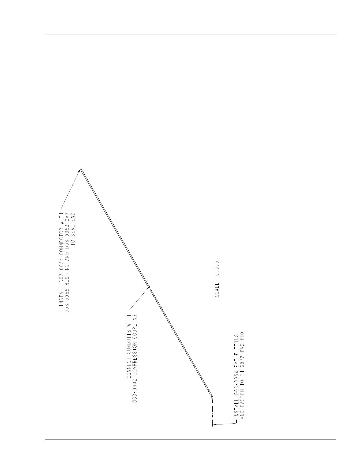
DR YING CHAMBER HILIMIT ROTARY
SWITCH INSTALLATION
Assemble 1/4” shaft to rotary switch with 1/4”
coupler and rolled pins. Next Screw 1-1/4” pipe
coupler to bottom of rotary switch. Insert 1-1/4”
pip through adjustable roof mount weldment.
Leave 1-1/4” pipe sticking out the top of the
weldment 3” as shown in Diagram. Install paddle
to 1/4” shaft assembly with coupler and rolled pins.
Switch assembly is now ready to mount to roof.
2003 Top Dry Service School
3.00”
COMPRESSION COUPLER
ROOF MOUNT PLATE
8
Page 9
2003 Top Dry Service School
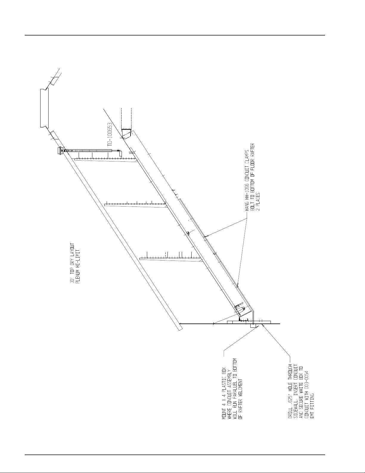
TOP DRY PLENUM HI LIMIT INSTALLATION
1. Assemble two pieces of conduit together with coupler.
2. Mount conduit clamps to conduit assembly.
3. Locate conduit assembly on the bottom of a rafter at least 2 feet to one side of the fan
entrance. Do not install between two f an entr ance s.
4. Mark bin wall where conduit will pass through and drill a hole just large enough to allow the
conduit to pass through. Seal this with caulking when complete.
5. Install white PVC box assembly on outside of bin wall.
6. Insert 10’ capillary into condu it assembly.
7. Connect SJO cord to hi limit and connect wires to terminals 20 and 21 on the master fan
terminal strip. These terminals are J7-08, and J7-03.
9
Page 10
2003 Top Dry Service School
10
Page 11

2003 Top Dry Service School
GSI / Top Dry
Software Revisions
11
Page 12

2003 Top Dry Service School
N
p
p
N
Network Autoflow Display Board Software Revisions
*********************************************************************
VERSION: 2.15 REVISED BY: Steve Logue RELEASE DATE: Oct 17, 2002
OTE: This Version does NOT support Wat chdog and the Heater Version MUST be 1.09. HEATER VERS – 1.09 IO
VERS – 1.07
1) The "FAN DELAY" is now called "MOTOR DELAY".
2) Added a way for GSI to reset total hours.
3) Here is a list of switches/features which can be found under the setup screens accessed via holding in on MODIFY whil e
owering on the Control Power.
Below is a description for each defin in g w hat it means t o disable/enable them :
i)
AIRSWITCH
requirements for the burner
regardless of the actual air switch state.
ii)
LOW LE VEL SWITCH
state of the rotary swi tc h.
When disabl ed the dryer will think the l ow level switch is always covered.
iii)
WET TANK SWITCH
always covered w it h grain.
iv)
START FANS WITH
Disabled means dryer will
start according to drying chamber low level switch.
v)
AERATION FAN BYPASS
dryer shutdow n.
4) The REFILL TIM ER and the TIME UNTIL LOAD OFF screens are only shown w hen t he dr yer is set for Autobat c h mode.
5) There are two more settings available under the "Power on and Modify key in" se quence for the user to set how many de gr ees a
measured temperature can
exceed a set poi nt w ithout causing an overheat. The user can set 10 -> 50 degrees above the setpo in t to be an overheat conditi on.
The default for the plenum
temp is 20F and the default for the grain temp is 30F.
6) The low level rotary switch function is the same as it was in 2.14, but now instead of giving a warning which states "DRY
CHAMBER EMPTY " whe n
it become s un c overed it gives "LOW LEVE L SW EXPOSED ."
7) Added an Out of Grain Timer. The time value can be changed under the setup but ton. This timer starts whenever either fill
systems is running and the load
switch is in the auto position. The timer is reset when both load augers stop. If the timer runs out of time an OUT OF GRAIN
warning is issued. The
default is 20 minutes. Any time the value of this Timer is change d th e new val ue takes effect immediately.
8) Changed warning for wet bin empty to state "WET BIN SW EXPOSED" instead of saying “DRYER OUT OF GRAIN”.
9) Renamed "FILL 1 DE LAY" to "FIL L SY S TE M #1 ". Changed name of "FILL 2 DELAY" to "HI LEVEL SW". The HI
LEVEL SW delay is always
available on both one and two fill sys t em dr yers and is used to make sure the dryer is full s o you don't get bogus shu t downs. The
FILL SYSTE M #1 delay is
only available when you are set for two fill systems and it is use d to es ta blish auger cleanout time.
10) If the Storage Bin Hig h Lim i t is det ected as failed (the N.C. pin and the N.O. pin from the swit ch are both reporting the sam e
voltage, 0 or 12 volts) a
warning is reported as “BIN HI LIMIT SW BAD”.
11) If wet supply rotar y switch becomes unco ver e d t her e i s a tim er w hi ch m us t expire before a warni ng is given. This timer/delay
was called "AUX 1 DELAY",
but is now termed "WET BIN SW. delay" It is found under t he DELAYS key.
12) The time a user has to think about making a chang e to a timer/setpoint bef or e i t au tomatically proceeds to the next selection
screen has been doubled.
13) Changed the name of de lay/timer "LOW LEVEL TIMER" to "LO L EVEL SWITCH."
14) Enabled the "START FANS WITH HIGH" switch function. There was previously a screen available to select this function, but
it was never active.
15) The cool down timer is now set to the reload valu e of the cool timer whenever any one of the four foll ow i ng s hutdowns takes
lace:
i) Dry and Hold swit c h i s turned to on state. ii) Grain falls awa y from wet bin supply switch.
iii) Storage chamber is full. iv) Dryer is o ut of gr ain.
16) Fans Off Delay now defaults to 0 minutes i nstead of 1 minute and has an upper limit of 5 minutes. This delay can be f ound
under the “delay” key.
17) The dryer functions the same whether the l oad s w i tch is in auto or on, but the o ut of gr ai n timer only times dow n while the load
switch is in the auto position
and one of the load a ugers i s run ni ng.
*********************************************************************
VERSION: 2.14 REVISED BY: Steve Logue RELEASE DATE: Sept 20, 2002
OTE: This Version does NOT support Wat chdog and the Heater Version MUST be 1.09 not the Watchdog version 1.10.
1) Fixed software so the bur ner differential could be set to one degre e a nd i t would remain there after loss of power.
-> Enabled means you will get a shutdown when a fan loses airflow. Disabled will satisfy the dryer's airflow
-> Enabled mea ns th e dr ying chamber low level sw itch will act as normal, i.e, w ill in dicate the real
-> Enabled means this switch will act as normal. Disabled means the dryer will think this switch is
HIGH -> Enabled means the dryer will start f ans according to state of dr ying chamber hi level switch.
-> Enabled means the B Y PASS is active, which all ows t he aer at ion fan to continue to ru n af ter a
12
Page 13

2003 Top Dry Service School
p
N
N
g
*********************************************************************
VERSION: 2.11 REVISED BY: Steve Logue RELEASE DATE: October 27, 2000
1) Burner differential would not stay at 1 deg F w hen the dryer was tur n of f , usi ng 2.10, now it does.
2) When grain reaches the St or age Chamber Rotary Switch, the dryer will enter a "Cool Down Mode". The fan will run and coo l
thegrain for 10 minutes before
shutting dow n due to a Storage Cham ber Full error.
3) When grain falls away from the Wet Supply Rot a ry Switch, th e dryer will ente r a "Cool Down Mode" after the fill syst em shut
off. The fan will run and
cool the grai n f or 10 minutes before shut t i ng down due to a No Wet Supply error.
4) When the Dry & Hold switch is placed in the "On" position the dryer will enter a "C ool D ow n Mode" for 20 minutes bef ore
stopping. This only happens at
the end of the dry cycle.
5) Corrected a problem with t he Fans Off Delay. If there is tim e on this delay, the fans and heaters will shut off duri ng the unload
cycle, after the unl oad cycle
is complete the delay counts down. The fans and heaters will not start again until the delay has reached zero.
6) Corrected a problem with the Time Until Load Off percentage set in the set-up mode. Now, in Auto batch only, the Fill Systems
will shut off if grain has not
reached th e dr y chamber high level rotar y s w i tch within the set perce nta ge of the dry timer is comple te d. Example: 1 hr dry
time, 50% Time Until Load off.
The fill systems w i ll shut off regardles s of ro tary switch status aft er 30min has expired.
7) Corrected a problem with t he Refill Delay. Now, i n Au t o bat ch O nly. The Refill Delay begins to count down af ter t he unload
cycle is completed. If grai n
has not reached t he dr yi ng chamber low level rot ary sw i tch before this delay reac hes zer o, a dr y chamber empty error is gi ven.
*********************************************************************
VERSION: 2.10 REVISED BY: Steve Logue RELEASE DATE: Sept 11, 2000
1) Changed the Minimum Burner Differential t o 1 Deg Fahrenheit
2) Fixed the problem wh er e th e bur ner w as not shutting off whe n th e Dry & Hold switch was pla ced i n t he "O n" position, the Dry
Cycle was complete, and the
Dryer was in the Cool Cycle. Now, when the Dry & Hol d swit ch i s pla ced i n t he "O n" position, and the Dry Cycle is complete,
the dryer will shut th e bur ner
off and will cool for the amount of ti m e on t he C ool Timer before sto ppi ng.
3) Fixed a problem wher e the dr yer w as not shutting down wit h an "O ut of Grain" error when the Wet Supply Ro t ar y Sw i tch was
exposed. Now whe n th e Wet
Supply R otary Switch is exposed, the Fill #1, and Fill #2 delay will count down and shut off Fill System #1 & #2, then the dryer
will shut down with an "Out
of Grain" er r or. If there is still grain aga inst the Low Level Rotary Switch, the dryer can be rest ar t ed by pr ess i ng the Stop switch
to clear the error, turning
the Load Auger switch to the "Off" pos i t i on, and pressing the Star t switch. When the Star t swi tch is pressed the screen will say
"Press <Enter> to Dry
Remaining Grain". If the <enter> button is pressed the dryer will restart. NOTE: If the Load Auger switch is left in the "Auto"
osition an "Out of Grain"
error will be gi ven on startup.
*********************************************************************
VERSION: 2.09 REVISED BY: Steve Logue RELEASE DATE: May 15, 2000
1.) Selection screen for On-Off burner. This cannot be used i n conjunction with di es el bur ner .
OTE: Must change heater software also. Use fol lowing version number or higher: Heater ==> 1.09
*********************************************************************
VERSION: 2.08 REVISED BY: Steve Logue RELEASE DATE: May 12, 2000
1.) Changed the burner differential setup screen to correctly display Celsius temperatures.
2.) Now only a year above 2000 may be ent er ed upon setting the dat e.
3.) Burner differential is now gr eater than 1 and less th an 10 degrees.
*********************************************************************
VERSION: 2.07 REVISED BY: Steve Logue RELEASE DATE: April 25, 2000
1.) Changed the checksum m ethod for the networ k t o help insure data integrity.
2.) Force aeration fan to start bef or e drying fans start , un less aeration switch is in off position.
3.) Load systems can not start for five seconds after start of system.
OTE: Must change heater and I/O softwar e also. Use following versi on number or higher:
*********************************************************************
VERSION: 2.06 REVISED BY: Steve Logue RELEASE DATE: April 20, 2000
1.) Stopped the abi lity to change the grain setp oi nt from heaters.
*********************************************************************
VERSION: 2.05 REVISED BY: Steve Logue RELEASE DATE: March 30, 2000
1.) Fixed a problem wit h fan 1 reporting air sw itch already engage d if f an 2 had not started yet .
2.) Fixed the low level disabling softwar e s o a w ar ning is not reported when the high level grain switch detec ts gr ain without the
*********************************************************************
VERSION: 2.04 REVISED BY: Steve Lo
Heater ==> 1.07 IO ==> 1.07
low level detec ting grain.
ue RE LE A SE DATE: Feb 25, 2000
13
Page 14

2003 Top Dry Service School
p
*********************************************************************
VERSION: 2.01 REVISED BY: Steve Logue RELEASE DATE: October 4, 1999
1) Attempted to fix the pr oblem of grain setpo in t ch anging by itself.
2) Fixed problem of batch dry e r always shutting down with a "DRYING CHAMBER EMPTY" war ni ng. A delay called the "RE FILL TIMER" allows the
dryer to fill back up.
*********************************************************************
VERSION: 2.00 REVISED BY: Jeff Falconer RELEASE DATE: January 6, 1999
1) Fixed hour timer so dryer w i ll now show running time of dr yer .
2) Changed the way the dryer s hut dow n when using the dry and hold switch, now it will cool the grain usin g the cool timer before it s hut s down to prevent hea t
buildup of grain past the grain temp set points thereby causing a shutdown condition. Works in Autoflow and AutoBatch modes.
3) Fixed the clock to properly roll over in the year 2000.
4) Added a user batch coun t an d us er tim er i ndependent from th e Total batch and Total tim e all ow i ng monitoring of di f f e r ent us er s dr ying grain or diff er ent
fields for compar ison of drying time.
5) Added a test procedure for the keypad. Turning all of the control switch es t o th e right (on position) and holding in the stop switch while turning on the
control power acti vates it. User can now test each individual keypad switc h f or m alfunction or stuck keys. (Taken out in 2.03)
6) Added control switc h testing by pressing and hold the plenum and gr ain switches in while t ur ni ng on the control power. Thi s w ill allow the user to test for
failed switches or computer failure to detect switch positi on changes. (Changed in 2.03 to turn power on w ith H elp key depressed)
7) Removed garbage displayed when user selected to view total runni ng time and total batches.
8) Added a check to make sure the dump switch is always i n th e A ut o pos i stion. Otherwise if left in manual close will caus e th e dryer never to dump.
9) Fixed several bugs t hat were reported to use by users and dealers.
10) I added the ability to reset the Total Dryer running time by pressing the HOUR and RESET button together and turn on the dryer.
11) Removed watchdog option in Extended setup mode sin ce w a t chdog has not been impl em ented yet.
12) Changed the wording to some of the error messages concerning th e ro tary switches to help eliminate some confusion of which switch was at fault.
13) Moisture contr ol light w ill now flash to give a visual indication that t he dr yer is in temperature hold.
*********************************************************************
VERSION: 1.06 REVISED BY: STEVE LOGUE RELEASE DATE: November, 98
1.) Fixed dryer so the grain hi limit occurs at 20 F above the grain temp setp oi nt.
2.) Made timeout on the open/close of the actuator 20 seconds ins te a d of 15 se conds. This extra tim e w as added to compensate for the weaker batteries taking
longer to close the chutes.
*********************************************************************
VERSION: 1.05 RELEASE DATE: September, 98
1.) Made the out of grain t imer active.
*********************************************************************
VERSION: 1.04 RELEASE DATE: July, 98
1.) The application of 12v to terminal number j1-20 will shutdown the dryer and give an indication that the bin is full due to the high level of s t at ic pres sure
within."BIN AIR PRESSURE LIM" will be displayed on screen's top line until the user corrects the problem. (Originally looked for lack of 12v, fixed in
2.00)
2.) Corrected the hour met er pr oblem.
3.) Changed how the dry tim er is displayed: Now when the dr y tim er goes to zero it will begin counting upward at the user s et time as long as the dryer rema ins
in temp hold.
*********************************************************************
VERSION: 1.03 RELEASE DATE: March, 98
1.) Added software t o allow the aeration fan to cont i nue r unning even if there was a dr yer s hutdown. The aeration fa n BYPASS mode must be sel ect ed under
setup.
*********************************************************************
VERSION: 1.02 RELEASE DATE: Jan, 98
1.) The Bin high limit rotary sw itch i s moni t or ed in both states to insure that a switch failure has not taken place. If both sw i tches are in the same state a switch
failure is report e d.
*********************************************************************
VERSION: 1.01 RELEASE DATE: NO OFFICIAL DATE ASSIGNED
1.) Added burner differ ential adjustm e nt to b e se t at m as t er under extended setup.
2.) Gary Woodruff 's sof twa re f or hol ding the fans off during a portion of the dr y cycle. This is adjusted under delays.
3.) Attempted to make the dr yer dry remaining grain when a wet supply em pty error takes place.
4.) Added software t o display a negative incr em ent ing counter, where the dry timer used to be, dur in g t e mp hold. (Changed in 1.04)
*********************************************************************
VERSION: 1.00 RELEASE DATE: SEPTEMBER 16, 1997
1.) We changed resist or num ber 107 on the displa y board from 10K to 3.0K to allow the contrast to work without resetti ng the computer.
2.). Put in a contrast adjustment for the display. While turning the cont r ol pow e r on, hold in on the screens key, and this will enter t he c ontrast adjustment mode.
Now use the UP/DOWN arrow keys to adjust. If the screen is solid black press the down arrow key, if nothi ng appears on the screen pr es s th e up ar r ow
keys. NOTE: You ca nnot hold in on the UP/DOWN arrow keys to adjust , you must continue t o pr ess and t hen release them or not hing will happen.
3.) Put Software in for 3
*********************************************************************
VERSION: 0.05 RELEASE DATE: 1996
This was the first version released for customer o
rd
Fan and Heater.
eration. This particular ver s i on could only control 2 Fan and Heaters.
14
Page 15

2003 Top Dry Service School
G
b
Heater and Batch Top Dry Revisions
--------------------------------
0.30 Released OCTOB E R 23, 1998
------------------------------------------------------------
1) FLAME TIME OUT IS NOW 10 SECONDS. THE IGNITOR SHUTS OFF IN ABOUT 7.5 SECONDS.
0.29 Released OCTOB E R 22, 1998
------------------------------------------------------------
1) ELIMINATE THE DEISEL OPTION -- FORCE THAT FLAG TO ALWAYS BE RESET. THIS CAUSED A 36 SECOND FLA
TIME OUT WHICH THE HARDWARE IS NOT SETUP TO ACCEPT. IF DEISEL OPTION IS REQUIRED AT SOME LATER
DATE -- WILL HAVE TO MODIFY SOFTWARE TO REDUCE FLAME TIME OUT BACK TO 12 SECONDS MAX OR
CHANGE THE HARDWARE.
2) DEFAULT FAN DELAY = 0 SECONDS ( FOR SLAVES )
0.28 Released August 24, 1998
------------------------------------------------------------
1) CREATE O / noO FLAG -- FOR EITHER IGNITOR OR HOT SURFACE IGNITION -- WHEN SET THIS IS USED FOR A
HOT SURFACE IGNITION SYSTEM -- SO THAT AT THE END OF THE PURGE DELAY THE IGNITOR COMES ON FOR 5
SECONDS BEFORE THE GAS VALVE TURNS ON. NOTE: I DID NOT USE I / noI BECAUSE IF THIS SOFTWARE WAS PUT
ON AN OLD DRYER -- IT WOULD DEFAULT TO noI -- IF THEY DID NOTHING. SINCE H / noH IS ALREADY BEING
USED FOR HUMIDITY -- I JUST USED O.
2) WHEN THE " O " FLAG IS SET -- AFTER THE 9 SECOND IGNITOR PERIOD THE IGNITOR DOES NOT TURN OFF
3) IN THE " O " MODE A FLAME OUT CAUSE THE GAS VALVES TO GO OFF FOR 5 SECONDS WHILE THE HOT
SUFACE INGITION COMES ON. THE WAY I DID THIS WAS TO RESET THE PURGE TIMER TO 5 SECONDS -- SO ON
THE DISPLAY TH E " PURGE " COMES UP -- THIS WA S THE EASIEST WAY TO ACCOM PLISH THI S.
4) CREATE d / nod FLAG -- FOR DIESEL FIRED SYSTEM. THIS SYSTEM HAS NO PURGE DELAY ( ACTUALLY 1
SECOND PURGE ) AND A 36 SECOND FLAME OUT TIME.
?????????????????????????????????????????
SHOULD THERE BE A LITTLE MORE PURGE DELAY --- SAY 5 SECONDS INCASE SOMEONE ACCIDENTLY SET THE
WRONG FLAG.
5) IF THE OPERATOR SET BOT THE " O " AND " d " FLAG THE " d " FLAG WILL NOT SET.
0.27 Released August 22, 1998
------------------------------------------------------------
1) Fixed problem in the Non Top Dry where after 30 minutes Error 3 shut the dryer down.
0.26 Released April 2 9, 1 998
------------------------------------------------------------
1) CHANGE FLAME OUT TIME TO 12 SECONDS -- IGNITOR SHUTS OFF IN 9 SECONDS -- 3 SECONDS LATER IF NO
FLAME -- SHUT DOWN -- NO FLAME. (CHANGED IN .30)
2) INCLUDE " FLAME " SYMBOL IN THE AMBIENT TEMPERATURE AND HUMIDITY MODES
3) ALLOW HUMIDITY DIFFERENTIAL TO BE SET TO 2 %
4) DON'T DESTROY " MODE " REGISTER WHEN EXITING THE PROGRAM MODE
0.25 Released April 2 7, 1 998
------------------------------------------------------------
1) Add a mode select for t he hum i di ty and ambient temperature. Using the mode sw i t ch ( Fan bypass ).
C.24 ???????????????????? ??
C.23 Released OCTOBER 29, 1997
------------------------------------------------------------
1) FIXED PROBLEM WHERE IF BOTH THE MASTER AND SLAVE HAVE THEIR OWN INDEPENDENT ERRORS -- THE
SLAVE DOES NOT FLICKER
BACK AND FORTH BETWEEN IT ERROR AND THE MASTER ERROR -- SLAVES ERROR HAS PRIORITY ON THE
SLAVE UNIT AND THE MASTER HAS PRIORITY ON MASTER UNIT.
2) IF THERE IS AN INCONSISTANCY BETWEEN MASTER AND SLAVE ( ERROR 9, 10 OR 11 ) -- THE MASTER TRIES
RESENDING THE IGNITOR COMMANDS 50 TIMES AND RECHECKING BEFORE ISSUING THE ERROR
.23 Released OCTOBER 22, 1997
------------------------------------------------------------
1) EXTEND THE IGNITOR ON TIME TO 14 SECONDS AND THE LAST 4 SECONDS SHUT THE IGNITOR OFF (changed in
.26)
A.23 Released OCTOB ER 15, 1997
------------------------------------------------------------
1) ALLOW 20 SECONDS FOR ILLEGAL FLAME SENSE
15
Page 16

2003 Top Dry Service School
SECONDS -- EXIT THE PROGRAM MODE.
0.22 Released OCTOB E R 22, 1996
------------------------------------------------------------
1) FIXED THE PROBLEM WHERE IF YOU SET IN 3.2 HOURS -- THE HOURS IMMEDIATELY WENT TO .32 WHEN YOU
EXITED THE PROGRAM
MODE
2) *CLEARING OF THE NOVRAM IS NOW ACCOMPLISHED BY POWERING UP WITH THE PROGRAM SWITCH HELD
DOWN ( LOWER LEFT *
*SWITCH ) -- WHEN THE " 0 " COMES UP -- ENTER A " 7 " WITH THE INCREM EN T SW ITCH -- THEN PUS H THE
PROGRAM SWITCH AGAIN *
*" - - - " COMES UP -- YOU HAVE 2 SECONDS TO DEPRESS THE INC DEC SWITCHES AT THE SAME TIME TO
CLEAR THE NOVRAM *
0.21 Released OCTOB E R 2, 1996
------------------------------------------------------------
1) FIXED THE PROBLEM THAT I CREATED IN VERSION # 0.20 WHERE THE ERROR 3 CAME ON -- SPARE
TEMPERATURE OPEN
2) WHEN IN TOP DRY MODE THE CYCLE FLAG IS ALWAYS SET
0.20 Released SEPTE MB ER 12, 1996
------------------------------------------------------------
1) CREATE A NEW MODE THAT WILL MAKE IT SO THAT BOTH THE GRAIN TEMPERATURE MUST EXCEED THE
LIMIT AND THE DRY TIME
MUST BE EXCEEDED BEFORE ADVANCING TO THE COOL CYCLE ON THE TOP DRY
2) IF THE GRAIN TEMPERATURE GETS TO 200 -- ALWAYS ADVANCE TO THE COOL CYCLE -- IN ALL MODES OF TOP
DRY, ---> IF THE 10
MINUTE GRAIN TIMER HAS GONE TO 0.
3) FIXED PROBLEM ( I THINK ) WHERE THE TEMPERATURE WOULD MOMENTARILY JUMP UP TO 275 DEGREES -WHEN THE THERMISTOR
SWITCH-OVER OCCURED ON THE BOARD
0.19 Released JUNE 8, 19 96
------------------------------------------------------------
1) HUMIDITY SOFTWARE
0.18 Released MARCH 1 3, 1996
------------------------------------------------------------
1) DON'T ADVANCE TO COOL CYCLE IN TOP DRY MODE FOR 10 MINUTES AFTER STARTING THE DRYER
-- ALLOW THE GRAIN TEMPERATURE SENSOR TO STABILIZE
2) WHEN THE SLAVE POWERS UP WITH THE FAN ON -- THERE WAS A LOT OF DISPLAY FLICKER -- CORRECT THAT
PROBLEM
0.17 Released OCTOB E R 17, 1995
------------------------------------------------------------
1) FIXED THE PROBLEM WITH THE TOP DRY MASTER NOT SHUTTING THE FAN OFF WHEN THE SLAVE GOT AN
ERROR
2) WHEN GETTING ONE OF THE LIMIT ERRORS, ETC -- THAT JUST DISPLAYS A LEGEND -- ON THE MAIN DISPLAY
INSTEAD OF DISPLAYING
TEMPERATURE -- DISPLAY: 0 0 0
ERROR
0.16 Released OCTOB E R 16, 1995
------------------------------------------------------------
1) Raised the Error 12 V oltage Limit from >155 to >195 volts for 120 volt systems. <155 vol ts st ill the error 12 limit f or 240 volt
systems.
0.15 Released OCTOB E R 14, 1995
------------------------------------------------------------
1) CORRECTED THE PROBLEM WHERE WITH CERTAIN ERRORS YOU COULD NOT VIEW THE AMOUNT OF TIME
THE DRYER HAS BEEN
DOWN DUE TO ERROR CONDITION
2) IF THE " STANDARD DRYER " ( NOT TOP DRY ) FINDS A SLAVE INCONSISTANCY ERROR -- ERROR # 9, 10 O 11 -IT WILL TRY RESTARTING
THE SLAVE FOR 5 SECONDS BEFORE IT GIVES UP
3) CORRECTED THE BUG IN VERSION 14 SOFTWARE WHERE THE REMAINING HOURS WERE NOT STORED FOR
DRY AND COOL TIME -- ALL
16
Page 17

2003 Top Dry Service School
)
CAN VIEW THE HOURS THAT HAVE PASSES SINCE THE SHUT DOWN BEGAN. MAX NUMBER OF HOURS = 218
HOURS ( 9.1 DAYS ) *
2) ADDED ERROR NUMBER 13 ==>> + 11 LIMIT SHORTED
3) LIMIT MAX TEM P ERA T U RE SE TTI NG TO 23 0
0.11 Released AUGUST 16, 1995
------------------------------------------------------------
1) MAKE THE SPARE RELAY ACT THE SAME AS THE FAN RELAY -- BOTH OPEN AND CLOSE AT THE SAME TIME
0.10 Released July 12 , 19 95
------------------------------------------------------------
1) If the Heater shuts dow n due to a “ Illegal Flame “ Se nsing problem – Flame o n wh en no gas valves are on Error 7. Leave the
Fan on till that problem goes away. When the Heater Control detect No Flame – The Fans are Shut Down.
The Fans are left in the State they were in when the error was detected. That is – If the Error 7 occurs on the Power Up – Don’t turn
the Fans on – That must be due to some other prob lem.
In a Master / Slave heater – Only the Heater with the Flame since problem keeps it’s fan on.
In the Timed Shut D ow n Modes the Fans are left on t ill it is confirmed that the Fla m e has gone away. This is for Top Dry and
Regular Fan and Heater.
In the Top Dry when the Grain Temperature excedes the limit – The Fans are left on till it is confirmed that the Flame has gone away.
0.09 Released May 27, 1995
------------------------------------------------------------
1) In all test modes shut the outputs off.
2) ON May 31, 199 5 -- changed the flash decod e bytes to program the entire chip rather than th e fir s t 256 k bi ts -- left the version at
0.09
0.08 Released April 1 8, 1 995
------------------------------------------------------------
1) Fixed the probl em w her e w hen the humidity was to o high or the grain temp was to high the display flas h r eal f as t.
0.07 Released Good Friday i n t he Y ear of O ur Lord 1995
------------------------------------------------------------
1) Fixed the probl e m w it h t he er r or not being displaye d on t he top dry remote.
2) Allow the remote to reset the Coo l an d Dry timers if the Inc and Dec switches are depr essed at the same time.
0.06 RELEASED 3/23/95
-----------------------------
1) IF THE HUMIDITY INPUT IS SHORTED TO + 11 VOLTS ADVANCE TO THE COOL CYCLE
2) IF THE HUMIDITY IS TO HIGH TO BEGIN WITH -- THE D_RH AND D_PERCENT FLASH ON AND OFF FOR A FEW
SECONDS
0.05 RELEASED 3/23/95
-----------------------------
1) ADDED WATCH DOG SOFTWARE
0.04 RELEASED 3/06/95
-----------------------------
1) FILT ER THE FLA M E PRESEN T INDICATOR
2) FILTER THE ERROR 12 -- WRONG VOLTAGE ERROR
0.03 RELEASED 1 2/ 05/94
-----------------------------
1) IN THE TOP DRY MODE WHEN AN ERROR OCCURS WHILE RUNNING -- EITHER COOL OR DRY TIME -- THE
TIMER IS SAVED AND AFTER
POWER OFF AND ON AND CORRECTING THE ERROR THE TIMER RESUME WHERE IT LEFT OFF.
YOU CAN CLEAR THE TIMER BY DEPRESSING THE INC AND DEC SWITCHES AT THE SAME TIME.
2
17
Page 18

2003 Top Dry Service School
PROGRAMMABLE DELAY FOR TOP DRY FANS *
The dry time and cool time " car r ots " on the display bot h f lash indicating -it is i n the program delay time m ode.--- NOTE: THIS CAN BE DONE ON THE
MASTER
0.01 RELEASED 1 0/ 11/94
-----------------------------
1) ADDED MODE TO ALLOW TOP DRY TO HAVE REMOTE PLUS 2 SLAVES
2) ADDED ERROR # 12 -- WRONG VOLTAGE ERROR
3) PUT REVISION LEVEL ON POWER UP SCREEN
* 4) IF THE START SWITCH IS HELD IN THROUGH THE POWER UP SCREEN -- TILL AFTER THE VERSION NUMBER DISPLAY -- ALL
SEGMENTS
LIGHT TO ENABLE EASIER DECAL ALIGNMENT. *
ORIGINAL RELEASE 9/29/94
-------------------------
18
Page 19

2003 Top Dry Service School
Series 2000 Batch Errors
* Dipswitch Settings
* Error Messages and solutions
* Operation TIps
GSI / Top Dry
and troubleshooting
19
Page 20

2003 Top Dry Service School
Configuration Dip
Switches (Normally Done
At Gsi)
These switches are used to configure the heater control for various
types of heaters.
Multiple heaters connected together
through the serial link.
Top Dry stand
alone with no remote display at the
bottom-dip switch
6 on/all others off.
Top Dry master
with a remote display at the bottomdip switch 6 & 7
on/all others off.
Top Dry master
with a remote display at the bottom
and one slave fan
heater-dip switch 6
& 8 on/all others
off.
Top Dry master
with a remote display at the bottom
and 2 slave fan
heater-dip switch
6, 7 & 8 on/all others off.
Top Dry remote
display at the bottom-dip switch 1 &
6 on/all others off.
Top Dry 2nd fan
heater-dip switch 2
& 6 on/all others
off.
Top Dry 3rd fan
heater-dip switch
1, 2 & 6 on/all others off.
20
The backside of the control board, showing the dip switch placement.
Page 21

2003 Top Dry Service School
Limit Switches
The following limit switch errors light up individually on
the heaters LCD screen:
PLENUM, HOUSING , V APOR, TEMP HI LIMIT
Multiple Heater Error Conditions
T wo or more heaters may be connected together through
the serial link. If the master cannot communicate with a
slave controller, the master will display "SLA" on the
main display and the "RX" "TX"
symbols will be flashing. If a limit switch error or one
of the error numbers 1 through 8 occurs, that error
is displayed on the slave where the error originates.
The master displays "SLA ERROR".
MISC ERROR NUMBERS
1 2 3 4 5 6
Plenum temperature probe 1
open
Plenum temperature probe 1
short
Grain temperature probe 2
open
Grain temperature probe 2
short
Airflow open
7 8 9 10 11 12
Illegal flame
sense
Error 7 is
most likely
caused by stuck
open solenoid.
Error 7 will not
shut down fan
until loss of
flame is detected
by control.
Flame probe
short error
Slave #1 inconsistent with master with either
the drying grain
flag or the LP
main solenoid or
cycle solenoidmost likely the
slave got reset
powering up
with the solenoids off
(Errors 9 through 11 are displayed only if multiple heaters are
tied together through serial link).
Note: Temperature sensor connection-the temperature sen-
sor (bolt) must always be connected to the master . In the case
of the Top Dry, both temperature sensors must be connected
to the master (unit at the top). Top Dry grain temperature
input is connected to J7 pins 14 and 18.
Slave #2
inconsistent
same as error 9
for slave #1
Slave #3
inconsistent
same as error 9
for slave #1
Airflow short
Wrong voltage.
Dip switch #5 is
the voltage selector switch. If
dip switch #5 in
"ON" that selects 240 VAC. If
the unit has only
120 V AC applied,
error 12 will
show up. If dip
switch #5
is"OFF" that selects 120 VAC. If
the unit has 240
V AC applied error 12 will show
up.
This is important because
if the fan heater
is set up at GSI
for 120 VAC and
the customer
connects to 240
VAC the heater
control will work,
but if allowed to
operate the solenoids will have
240 VAC applied
to them which
will damage solenoids.
21
Page 22

2003 Top Dry Service School
Error Details
Error #1 Plenum T emperature Probe Open. The two wires for checking this error are on terminals 24 and
25 they are labeled J7-12 and J7-13. The wires must be removed from the terminals to receive a correct
reading. This must be checked with a Ohm Meter . If the probe is open you will not receive any reading on
your meter because there is no continuity between the wires. It is like you cut the wire in half. If there is
resistance there is a certain resistance reading for current temperature of the probe. See Chart at the back
of this section to verify that the sensor is correct. If the sensor is correct you probably did not have a good
connection from one of your wires to the terminal strip.
Error #2 Plenum T emperature Probe Short. This error is indicating that the Plenum T emperature probe is
shorted. This will also need to be check with a Ohm meter and if it is shorted will read no resistance as if
you were checking both ends of one wire. Remember to disconnect the wires before checking.
Error #3 Grain T emperature Probe Open. This error is indicating the Grain T emperature Probe located in
the drying chamber on a leleveleveling band is shorted.. The terminals for checking the Grain T emperature
Probe are 22 and 23 and are labeled J7-14 and J7-18. The process for checking this error are the same as
in error #1. Remember to disconnect the wires from these terminals before checking them.
Error #4 Grain T emperature Probe Short. This error is indicating that the Grain T emperature Probe is
shorted. This is the same Probe as in error #3 and is checked like Error #2.
Error #5 Airflow Open. This error is indicating the airflow proving switch is in its open state and should be
closed verifying there is no airflow so the fan heater will start. This must be checked with a Ohm meter and
can be done directly on the airswitch terminals labeled N.O. And Common. This can also be checked on
the terminal strip between terminals 12 and 14. They are labeled J7-09 and J7-10. The Airswitch can
usually be adjusted and correct this error.
Error #6 Airflow Short. This error is indicating that the airswitch is stuck in both a normally open and
normally closed state and needs to be adjusted, cleaned, or replaced.
Error #7 Illegal Flame Sense. This error is indicating that there was a flame sensed at a time it should not
have. This is usually caused by a solenoid valve not closing properly . You can detect a solenoid not closing
properly by watching the pressure gauge on the gas train. After the unit cycles off the pressure gauge will not
drop immediately , it will gradually drop to zero or you can witch the flame and see if it is shutting off immediately or gradually burning out.
Error #8 Flame Probe Short. When this Error is given it can be either the flame probe is touching a metal
surface or The flame probe wire has shorted to ground somewhere. T o fix adjust the probe or replace the
wire to the to of it.
22
Page 23

2003 Top Dry Service School
W e use two (2) different types of sensors (NTC thermistor on the Series 2000, and an encapsulated
sensor on the E.M.C.S ) in our dryers. The resistance of the sensors varies according to the outside temperature.
For example, on the E.M.C.S. for every one (1) degree rise in temperature the resistance increases 4.8 ohms.
However, on the Series 2000 dryer , the sensor reacts just the opposite, the resistance rises with colder temperatures.
The charts displayed above will help when troubleshooting any sensor problems.
23
Page 24

Special Wire Terminals
p
2003 Top Dry Service School
SERIES 2000 BATCH TOPDRY TIPS
Operation Tips for Top Dry Batch
J7-10 or J7-13
Any unused third terminal on any network connector is also a 12 volt ground.
1. When ever you see 000 on the Screen there is an Error some where on the screen.
2. To F or ce a new time setting while the Dryer is runn ing Pus h the “Inc” (Up Arrow) and the
“Dec” (Down Arrow) keys at the same time
3. To change the Second Fan Start delay hold down the “Program Dry/Cool Timers” and “Program
Temperature”
keys and turn on the power switch. Note this must be done on the Master Fan and cannot be done of the
Slave
Fan or at the Remote Display.
4. Turning Dip Switch 3 ON disables the Air Flow monitoring function for testing. Remember to turn
OFF before
leaving the Dryer as loss of airflow will not shut down the dryer if the switch is left on.
5. You can select two modes for when the Drying Proces s stops.
A. Standard sett ing whic h will shut down if either Grain Temperature OR Dry Time is met.
B. Optional setting in which both Grain Temperature AND Dry Time must be met.
To change this setting use the followin g steps.
1. While holding the Program Key in turn Power switch on.
The Screen should read “0”
2. Release the Program button and press the “Inc” (Up Arrow ) key 3 time s.
The screen should read “3”.
3. Press the Program Button until you see “NoL” (Sta ndard se tting)
Press the “Inc” (Up Arrow) or “Dec” (Down Arrow) keys to change to “L”
on stand alone unit - 12 volt Ground for use with a tester.
“NoL” - Will s to p drying when meeting either the Time OR Temperature Settings.
“L” - Will stop drying only if both Time AND Temperat u r e S ett i n gs are met.
6. To Clear the NOVRAM
Hold down the Program key (lower left key) and power the unit up. When the “0” comes up Enter a “7”
with the
Increment key (Up Arrow) and then push the Program Key again. When the “--- “ comes up you have 2
Seconds
to depress the “Inc” (Up Arrow) and “Dec” (Down Arrow) keys at the same time.
(Do not do this unless you are told to or are at a last resort to fix inconsistent behavior of the board)
7. When an Error shuts down the Dryer you can determine how long ag o the shutdown occurred by
ushing the
“Dec” (Down Arrow) Key. It will read in hours with a maximum of 218 (9.1 days).
8. Drying Time has a minimum setting of 10 minutes no matter what time is set.
24
Page 25

2003 Top Dry Service School
11. DIP Switch Settings (Turn on Switches named and leave all others off)
Top Dry Master
Stand Alone - No Remote Display 6 ON
With Remote Display 6 & 7 ON
Top Dry Master with Slave
With or Withou t Remote Dis pla y 6 & 8 ON Slave 2 and 6 ON
Top Dry Master with 2 Slaves
With or With out Re m ote Displa y 6,7 & 8 ON First Slave 2 & 6 ON Second Slave 1,2 &6 ON
Top Dry Remote Display
12.
Temperature Sensor Testing
A. You can find charts with the Resistance readings at various Temperatures in the following manuals
Located in
PNEG-630 Portable Dryer – Trouble Shooting Fe b 1999. pdf
PNEG-377 Fan & Heater – Service Manual Feb 2000.pdf
The Batch Top Dry’s use the Thermister type sensors, the bolt st yle for the Plenum and the Grain Temperature.
You have to disconnect the wires before testing. Check the charts listed above for readings at othe r te m p eratures.
Resource 2002 CD
in the “
Resources – Manuals
1 & 6 ON
” Folder
Page 54
Page 50
(Portable Dryers | Trouble Shooting – Oper ating Tips)
(Fans and Heaters | Trouble Shooting Guide)
10-15-02
1.
25
Page 26

Series 2000 Autoflow Errors
and troubleshooting
* Error Messages and solutions
* Operation tips
2003 Top Dry Service School
GSI / Top Dry
26
Page 27

2003 Top Dry Service School
Error Messages
When the dryer shuts down the user can
quickly determine what caused the shutdown by
viewing the display on the dryer control panel. The
Electronic Monitoring Control System displays the error
message and sounds a warning signal to alert the user.
The displayed error conditions and their electrical cause
are as follows:
Burner 1 Loss Flame
The flame sensor in burner number one has
failed to detect flame. Either the burner failed to light
or the flame sensor needs to be adjusted. The flame
sensor is the sensor attached to the burner, and has a
single lead. If the burner is lighting but the unit is still
shutting down due to loss of flame the flame sensor
needs to be adjusted. The flame sensor can be adjusted
by bending it so it is immersed in flame. If the burner is
not lighting make sure that the dryer is getting fuel, all
solenoids are opening, and the ignitor is sparking.
Burner 2 Loss Flame
and automatically resets itself when cool. The vaporizer is adjusted by loosening the bolt and moving the
vaporizer coil away from the flame.
Fan 2 V apor High Limit
The LP gas vapor temperature sensor located
on the gas pipe train downstream from the vaporizer
coil on fan and heater number two has opened indicating that the vaporizer coil is running too hot and must be
adjusted. This sensor is set at 200 degrees Fahrenheit
and automatically resets itself when cool. The vaporizer is adjusted by loosening the bolt and moving the
vaporizer coil away from the flame.
Fan 1 Housing High Limit
The temperature high limit located on the
housing on fan and heater number one opened, indicating that the housing towards the bin has overheated.
This high limit sensor is set at 200 degrees Fahrenheit
and must be manually reset.
The flame sensor in burner number two has
failed to detect flame. Either the burner failed to light
or the flame sensor needs to be adjusted. The flame
sensor is the sensor attached to the burner, and has a
single lead. If the burner is lighting but the unit is still
shutting down due to loss of flame the flame sensor
needs to be adjusted. The flame sensor can be adjusted
by bending it so it is immersed in flame. If the burner is
not lighting make sure that the dryer is getting fuel, all
solenoids are opening, and the ignitor is sparking.
Fan 1 V apor High Limit
The LP gas vapor temperature sensor located
on the gas pipe train downstream from the vaporizer
coil on fan and heater number one has opened indicating that the vaporizer coil is running too hot and must be
adjusted. This sensor is set at 200 degrees Fahrenheit
Fan 2 Housing High Limit
The temperature high limit located on the
housing on fan and heater number two opened, indicating that the housing towards the bin has overheated.
This high limit sensor is set at 200 degrees Fahrenheit
and must be manually reset.
Plenum High Limit
An over temperature condition has occurred
inside the dryer plenum. The plenum high limit is set
automatically on the Hi-lo thermostat when the cycle
set-point is adjusted and resets automatically when
cooled. The lo-fire gas pressure needs to be lowered,
or the cycle setpoint on the Hi-lo thermostat needs to be
increased if the error is displayed frequently .
27
Page 28

2003 Top Dry Service School
Fan 1 Motor Overload
The thermal overload in the control box on fan
number one has tripped, indicating an overcurrent
condition. The overload must be reset manually .
Fan 2 Motor Overload
The thermal overload in the control box on fan
number two has tripped, indicating an overcurrent
condition. The overload must be reset manually .
Fan 1 Loss Of Airflow
The contacts on the airswitch, located in the bin
sidewall and attached to fan and heater number one,
have opened due to the fan not turning, or the airswitch
may need to be adjusted.
Drying Chamber Overflow
Bin Grain High Limit Full
The grain level in the storage chamber has
reached the storage chamber high level rotary switch
located 3 feet below the fan and heater(s). Grain will
have to be removed from the storage chamber before
the unit can be restarted.
Bin High Limit Switch Bad
The storage chamber high level switch has
failed. Both the normally open and the normally closed
sides of the switch are in the same state.
Out Of Grain
The out of grain timer has ran for longer than it
was set. Either you are out of grain or the fill system is
filling to slow .
The grain level in the drying chamber has
reached the drying chamber overflow rotary switch.
Grain will have to be dumped from the drying chamber
to the storage chamber before the unit can be restarted.
This error indicates that either the drying chamber high
level rotary switch is faulty or the time on the Load
delay or Aux. 1 delay needs to be lowered.
28
Page 29

2003 Top Dry Service School
W et Supply Empty Press <Enter> T o Dry Re-
maining Grain
Fill 1 Motor Overload
This message is displayed when the start button
is pushed and grain has fallen away from the wet
supply rotary switch and there is still grain against the
drying chamber low level rotary switch. If the enter
button is pushed the dryer will restart, but the fill
system(s) will not restart.
Cannot Start Dryer Wet Supply Empty
This message is displayed when the start button
is pushed and grain has fallen away from the wet
supply rotary switch and there is no grain against the
drying chamber low level rotary switch. Grain will have
to be put into the wet supply tank or the drying chamber
to start the dryer.
Low Level Switch Exposed
This message is displayed when grain falls
away from the drying chamber low level rotary switch
after the Wet Bin Switch Delay has reached zero. If
the error is being caused due to the settling of grain
after the fans start the time on the Wet Bin Switch
Delay can be lengthened.
The thermal overload in the fill system control
box for fill system number one has tripped, indicating an
overcurrent condition. The overload must be reset
manually .
Fill 2 Motor Overload
The thermal overload in the fill system control
box for fill system number two has tripped, indicating an
overcurrent condition. The overload must be reset
manually .
Aeration Overload
The thermal overload in the fill system control
box for the aeration fan has tripped, indicating an
overcurrent condition. The overload must be reset
manually .
Grain High Limit
The grain temperature in the drying chamber is
too high. The grain temperature reached a point where
it was five degrees less than the plenum cycle setpoint.
29
Page 30

2003 Top Dry Service School
b
p
Network Autoflow Tips
Present Version Numbers: Display 2.15 Heater 1.09 IO 1.07
Note: Disp lay version 2.14 and 2.15 will not work with Heater version 1.10 you must us e ve rs ion
1.09.
Important Software and Troubleshooting tips
Special Wire Terminals
for use with a tester.
1. When ever you install a new display board. After you flash the software in and restart you may see an
ERROR Message with some garbage characters or a negative number for temperature such as -2785
degrees. Do a Hard Boot by holding the Reset key and turn ing the power on to correct this stuck register
value.
2.
Always do a Hard Boot after ins t alling a new Dis play board.
3.
If you have a blank or all black screen see the Contrast Adjustment in Tip #1
4. Also when flashing new software to the IO Board turn off the load auger breaker(s). Due to a design
characteristic th e load auger(s) will run w h enever the IO b o ard is being f l as h ed.
5. If the Fan motors run, but the augers and aeration fan do not, make sure the 110 volt breaker on the IO
oard is turned on.
6. The newest Display boa rds (5/1/ 02)ca n now be used on e it her a Topdry or Po rta ble Dr yer. In the past a
Dryer Display board
had to have wires soldered in place for the Meter Roll Speed Pot and they can also be used on either a
Top Dry or Portable
Dryer. The past Top Dry Display board without these wires cou ld be used on a Top Dr y only. The
newest boards now have a
six pin connector that the Dryer Meter Roll Speed Pot is connected to.
7. If you get a plenum High Limit Error on startup w ith a new system or after installing new software on a
Two Fan Top Dry
check to see if a jumper from J7-3 to J7-15 fixes it.
8.
Grain Temperature Sensors
the flat of the floor.
- The third unused terminal on any network connector is a 12 V ground
are 10 ½” from the top of the floor rib. Older Top Drys were 14” from
Version Specific changes
Version 2.15 See separate Sheet at page 3 for subst ant ial changes in operation.
Version 2.14 1. Extended Setup is now accessed by holdi ng down the Modify key while
powering up
2. Low limits were set. 150 degrees for Grain High limit and 200 degrees for Pl enum
High limit.
Version 2.11
will be en ter ed.
The fan will run and cool the grain for
Full error.
When grain leav es the
out of grain error .
When the
stopping.
Version 2.06
Version 2.04
present
existing Plenum Air Switch.
Version 2.03
Version 1.02
to insure th at a switch
failure has not taken
1.
When grain reaches the Storage Chamber Rotary Switch
10 minutes
Wet Supply Rota ry Switch
Dry & Hold switch
Sto pped t he ab ility to change the grain setpoint from heaters.
Made all air switches active once again. New venturi Air Switches must be
on each fan where more then one fan is in use. Single Fan systems can cont inue to use the
The user can no longer go into
Release Date Jan of 98 the Bin High L imit rotary sw itch is now monitored in bo th sta tes
lace. If both switches are in the same state a switch failure is reported.
is placed in th e " O n " p osition the fan w ill Cool for
before shutting down due to a Storage Chambe r
. The fan will cool for
Extended Set Up
while the dryer is running.
a "Cool Down M o de"
10 minutes
before giving
20 minutes
before
30
Page 31

2003 Top Dry Service School
p
8)
Bin Hig h Pressure Limit
and give an indication
that the bin is full due to th e high level of static pressure within. "
be displayed on
screen's top line until the user corre cts the problem. (Originally looked for lack of 12v, reversed in
2.00)
9) There is a
Total time allowing
intermediate mo nitoring of batches and time. You
Key. You
Hour Meter
10)
Master & Slave Fan & Heater Dipswitch Setting s
Pg 42 Fan 1 (Master) #1 OFF / All others ON
Pg 50 Fan 2 (Slave 1) #2 OFF / All others ON
Pg 51 Fan 3 (Slave 2) #1 & #2 OFF / All others ON
Information above from PNEG -900 included in the CD in the Top Drys/Top Dry Fans & Htrs
Operation Charts folder as
99 Series 2000 AutoFlow - Insta lla ti on Pneg-900 July 1999.pdf
11)
Temperature Sensor Testing
1. You can find charts with the Resistance readings a t various Tempe r a tures in the following
manuals
Located in
PNEG-630 Portable Dryer – Trouble Shooting Feb 1999.pdf
Shooting – Operating Tips )
PNEG-377 Fan & Heater – Service Manual Feb 2000.pdf
Shooting Guide)
The Network Top Dry’s use the Thermiste r type senso rs , the bolt style for the Plenum and for the
Grain Temp erature.
You have to disconnect t he wires be fore tes ti ng. Che ck the charts listed above for readings at other
temperatures.
User Batch Count and User Timer or Hour Meter
Reset the User
by holding in the “
Resource 2002 CD
. The application of 12v to terminal number
BIN AIR PRESSURE LIM
independent from the Total batch and
Reset the User Batch
” key while turning on the “
Hours
in the “
Resources – Manuals
” Folder
Page 54
Page 50
Control Power
(Fans and Heaters | Trouble
will shutdown the dryer
J2-20
" will
Count from the “Setup”
”.
(Portable Dryers | Trouble
11)
SETUP
As of Software version 2.14 extended setup is reached by holding down the Modify key while
owering up.
A)
1) S et t he Clock.
2) Enable/Disable Air Switches. Disable f or adj us tment purposes only.
3) Enable/Disable Low Level Test. Enab le to ignore low level
4) Enable/Disable Wet Tank Test. Enable to run wi th no g r ain in Wet Tank.
5) Choose to start with fans on high or low. Low for US & Canada, High for Europe. (Did not
work until 2.15)
6) Aeration Fan Bypass Selection. When bypassed Fan does not shut down when Top Dry shuts
down.
7) Setup fill systems. One or Two Auger System.
8) Select type of dryer. AF1 = 1 fan or AF2 = 2 fan (Auto Flow) AB1 or AB2 (Auto Batch)
9) Select Temperature Scale - Fahrenhe it or Centigrade.
10) Select burner ON/OFF or HI/LO.
11) Select diesel burner.
Default = 20
Default = 30
– What can be changed and the order they show up on the screen. (See 2.15 for changes)
EXTENDED SETUP
12) As of Version 2.15 The Plenum High L imit is adj us tab le from 10 to 50 deg. above setpoint.
13) As of Version 2.15 The Grain High Limit i s adjus ta ble from 10 to 50 deg. above se tpoint.
: (Control Circuit must be off to access prior to version 2.14)
31
Page 32

Version 2.15 Changes
p
b
2003 Top Dry Service School
New Features
1.
Out of Grain Timer
time and shuts down the Top Dry, goes throug h the “Cle anout” of the Augers procedure and then gives an “
Warning. Default setting is 20 minutes . The “Load” switch “ON” position works exactly like “Auto” but ignores the Timer.
– Located under the “
” key. This Timer monitors how long the Load system runs inc luding delay
Setup
Out of Grain
”
2.
The High Limits on the Grain and Plenum Temperatures
oints that a “
above the set points. Both are settable from 10 to 50 degrees . These set ting s are acce sse d by turning on the “
while holding down the “M
determined there is no fire hazard. This in effect gives the system an “
3. The
the Top Dry and display of the “
variations in where the switch needs to be loca te d for differences in the moisture of the incoming grain. The New Out of Grain
Timer will make this De lay less likely to be used however.
4. Implemented the “
functional.
Grain or Plenum High Limit
odify
Wet Bin Rotary Switch
Start Fans with High
” key, in the
now has a
Wet Bin SW Exposed
” Warning will be displayed. Defaults are 30 de grees for the Gr ai n and 20 degree s
Extended Setup
Delay Setting
” Warning after grain no longer covers the switch. This is to allow for
” feature th at was previously listed in th e “
are now settable. User selects how many degrees above the set
Con trol P ower
, so they can be re set to allow op er ation after the User has
Emergency Cooling
accessed f r o m the “
Delay
” capability.
” Key. This will delay the shutting do wn of
Extended Setup
” list but was not
”
Changed Names
1. “
Fan Delay
start but also the time between when any Fan or Loa ding Moto rs star t.
2. When the
Chamber Empty
3. When the
4. The Delay f o rmerly called the “
Drying Chamber Low level Sw itch is now called the “
” is now “
Drying Chamb er Low Level Rotary Switch
Wet Bin Rotary Switch
Motor De lay
”.
” to better describe the fact that the delay not only delays the time between when the Fans
is exposed it will now say “
Out of Grain
” Delay which delayed the shutting down of the system if grain came off the
Lo level SW
is exposed it will now say “
Wet Bin SW Exposed
” Delay.
Lo Level SW Exposed
” not “
Dryer out of Grain
” not “
Dry
”
5. Under the
that were described as “
and Disabled means it is not monitored.
A. AIRSWITCH - Enabled means you will get a shutdown when a fan loses airflow. Disabled will satisfy the dryer's airflow
requirements for the burner regardle s s of the actua l a ir switc h state.
B. LOW LEVEL SWITC H - E n ab led means the d r y ing chamber lo w level switch w ill act as normal, i.e, w ill indicate the real
state of the rotary sw itch and will s hu t d o w n after the user set delay when u ncovered . When disabled the dryer will think the low
level switch is always covered.
C. WET TANK SWITCH - Enabled means this switch will act as normal, shutting down the system when uncovered.
Disabled means the dryer will think thi s switc h is always covered with grain.
D. START FANS WITH HIGH - Enabled means the dryer will star t fans according to stat e of d r ying cham ber h i level switch.
Disabled means dryer will star t according to drying chamber low level switch.
E. AERATION FAN BYPA SS - Enabled means the BYPASS is on an d th e Fan will run whenev e r th e “Cont r o l Power”
switch is tur ned on.
Extended Setup
accessed by holding down the “
” are now named as just the Switch itse lf . En abling the sw itch means it is monitored b y the System
Tests
Modify
” key while tu rn ing on the “
Con trol P ower
” those ite ms
Simplifications & Improvements
1. In the Auto Flow Mode the “
2. Instead of using a different name for the Delay which affe ct s the Dryin g Chamber Low Level Rotary Switch depending on
whether the system is set for a 1 fill or 2 fill system it will always be called “
3. Instead of Delay, that affects when the Fill 1 load sy s tem s tops in a 2 fill system , c hangi ng nam e s and com ing up on screen
when a 1 fill system has been set it will only show up when a 2 fill sy stem has been set and will be called “
4. The amount of time the Delays and other setting s sta y on the screen be fore movi ng to th e next has been doubled.
Refill Timer
” and “
Time until load off
” Batch only screens will not show up.
Hi Level SW
” Delay.
Fill System #1
” Delay .
5. The Cool Down feature which runs after an “
after t he system stop s because the “
een set for.
10-16-02
32
Stop and Hold
Out of Grain
” switch has been turned on, now Cools for whatever t ime the Coo l Tim er has
”, “
Storage Bin Full
” or “
Wet Bin SW Exposed
” shutdown or
Page 33

2003 Top Dry Service School
Software Diagnostics
* Series 2000 Batch Fan & Heater
* Series 2000 Autoflow Display
* Series 2000 Autoflow Fan & Heater
GSI / Top Dry
33
Page 34

2003 Top Dry Service School
Series 2000 Batch Fan / Heater
Initializing the Novram
• Turn the Control Power “ off “.
• Hold down the Program T emperature
switch.
• Turn the Control Power switch “on “
with the Program T emperature switch
held down.
• Press the Increase switch until 7 is on
the display .
• Press the Program T emperature switch
again.
• Y ou have two seconds to depress the
Increase or Decrease switches at the
same time.
• The NOVRAM has been initialized.
NOTE: The computer has now been cleared of all
memory , including the type of dryer it is and all
Set-up variables.
34
Page 35

2003 Top Dry Service School
Series 2000 Batch Fan / Heater
Programming Set-up Variables
• Turn the Control Power “ off “
• Turn the Control Power switch “ on “
with the Program T emperature switch
held down.
• Press the Increase switch until 3 is on
the display .
• Press the Program T emperature switch
again.
•C or no C will bill displayed.
• Use the Increase or Decrease switch to
toggle between C or no C.
C - Hi-Lo cycling heater
no C - On/Off cycling heater
• When the correct selection is on the
screen press the Program T emperature switch again.
•H or no H will be displayed.
• Use the Increase or Decrease switch to
toggle between H or no H.
H - Humidity sensor present
no H - No humidity sensor
present
• When the correct selection is on the
screen press the Program T emperature
switch again.
•F or C will be displayed.
• Use the Increase or Decrease switch to
toggle between F or C.
F - T emperatures displayed in
Fahren- heit.
C-T emperatures displayed in
Celsius.
• When the correct selection is on the
screen press the Program T emperature
switch again.
•L or no L will be displayed.
• Use the Increase or Decrease switch
to toggle between L or no L.
L - The dryer will advance to
the Cool cycle when the Dry
timer has reached zero and the
Grain temperature set point
has been met.
noL - The dryer will advance
to the Cool cycle when either
the Dry timer has reached zero
or the Grain temperature set
point has been met.
• When the correct selection is on the
screen press the Program T emperature
switch again.
35
Page 36

2003 Top Dry Service School
Series 2000 Batch Fan / Heater
CAUTION: DO NOT A TTEMPT BELOW PROCEDURE WITH GAS LINE CONNECTED.
Diagnostic Mode
• Turn the Control Power “ off “.
• Hold down the Program T emperature switch.
• Turn the Control Power switch “on “
with the Program T emperature switch
held down.
• Press the Increase switch until 8 is on
the display .
• Press the Program T emperature switch
again.
• Press the Program Dry time switch to
engage the Fan starter-Fan will be
displayed.
• Press the Increase switch to make the
ignitor spark-IN will be displayed.
• Press the Program T emperature switch
to open the LP and Main Solenoid- LP
will be displayed.
• Press the Start switch to open the
Cycle solenoid -CS will be displayed.
• Turn the control power “off” to exit
the Diagnostic mode.
36
Page 37

2003 Top Dry Service School
Series 2000 Autoflow Display
Keypad Test
• Turn the Control Power “of f”.
• Turn the Control Power switch “on”
with the Help Switch pressed.
• The Keypad Switches can now be tested.
Control Switch Tests
• Turn the Control Power “of f” .
• Turn the Control Power switch “on”
with the Plenum and Grain Switches pressed.
• The Control Switches can now be tested.
37
Page 38

2003 Top Dry Service School
Series 2000 Autoflow Fan / Heater
CAUTION: DO NOT A TTEMPT BELOW PROCEDURE WITH GAS LINE CONNECTED.
Diagnostic Mode
• Turn the Control Power “ off “.
• Hold down the Program T emperature switch.
• Turn the Control Power switch “on “
with the Program T emperature switch
held down.
• Press the Program Dry time switch to
engage the Fan Starter.
• Press the Program T emperature switch
to start theIgnitor.
• Press the Hours x 1000 switch to open
the Ssolenoid.
• Turn the control power “off” to exit
the Diagnostic mode.
38
Page 39

2003 Top Dry Service School
THE GSI GROUP , INC. ("GSI") WARRANTS ALL PRODUCTS MANUF ACTURED BY GSI TO
BE FREE OF DEFECTS IN MATERIAL AND WORKMANSHIP UNDER NORMAL USAGE
AND CONDITIONS FOR A PERIOD OF TWEL VE MONTHS AFTER RET AIL SALE TO THE
ORIGINAL END USER OF SUCH PRODUCTS. GSI'S ONLY OBLIGATION IS, AND
PURCHASER'S SOLE REMEDY SHALL BE FOR GSI, T O REPAIR OR REPLACE, AT GSI'S
OPTION AND EXPENSE, PRODUCTS THA T , IN GSI'S SOLE JUDGMENT, CONT AIN A MATERIAL DEFECT DUE TO MATERIALS OR WORKMANSHIP. ALL DELIVER Y AND SHIPMENT CHARGES TO AND FROM GSI'S F ACTOR Y WILL BE PURCHASER'S RESPONSIBILITY . EXPENSES INCURRED BY OR ON BEHALF OF THE PURCHASER WITHOUT PRIOR
WRITTEN AUTHORIZA TION FROM AN AUTHORIZED EMPLOYEE OF GSI SHALL BE THE
SOLE RESPONSIBILITY OF THE PURCHASER.
EXCEPT FOR THE ABOVE STATED EXPRESS LIMITED WARRANTIES, GSI MAKES NO WARRANTY
OF ANY KIND, EXPRESSED OR IMPLIED, INCLUDING, WITHOUT LIMITATION, WARRANTIES OF
MERCHANTABILITY OR FITNESS FOR A PARTICULAR PURPOSE OR USE IN CONNECTION WITH
(i) PRODUCT MANUFACTURED OR SOLD BY GSI OR (ii) ANY ADVICE, INSTRUCTION, RECOMMENDATION OR SUGGESTION PROVIDED BY AN AGENT, REPRESENTATIVE OR EMPLOYEE OF GSI REGARDING OR RELATED TO THE CONFIGURATION, INSTALLATION, LAYOUT, SUITABILITY FOR A
PARTICULAR PURPOSE, OR DESIGN OF SUCH PRODUCT OR PRODUCTS.
IN NO EVENT SHALL GSI BE LIABLE FOR ANY DIRECT, INDIRECT, INCIDENTAL OR CONSEQUENTIAL DAMAGES, INCLUDING, WITHOUT LIMITATION, LOSS OF ANTICIPATED PROFITS OR
BENEFITS. PURCHASER'S SOLE AND EXCLUSIVE REMEDY SHALL BE LIMITED TO THAT STATED
ABOVE, WHICH SHALL NOT EXCEED THE AMOUNT PAID FOR THE PRODUCT PURCHASED. THIS
WARRANTY IS NOT TRANSFERABLE AND APPLIES ONLY TO THE ORIGINAL PURCHASER. GSI
SHALL HAVE NO OBLIGATION OR RESPONSIBILITY FOR ANY REPRESENTATIVE OR WARRANTIES MADE BY OR ON BEHALF OF ANY DEALER, AGENT OR DISTRIBUTOR OF GSI.
GSI ASSUMES NO RESPONSIBILITY FOR FIELD MODIFICATIONS OR ERECTION DEFECTS WHICH
CREATE STRUCTURAL OR STORAGE QUALITY PROBLEMS. MODIFICATIONS TO THE PRODUCT
NOT SPECIFICALLY COVERED BY THE CONTENTS OF THIS MANUAL WILL NULLIFY ANY PRODUCT WARRANTY THAT MIGHT HAVE BEEN OTHERWISE AVAILABLE.
THE FOREGOING WARRANTY SHALL NOT COVER PRODUCTS OR PARTS WHICH HAVE BEEN
DAMAGED BY NEGLIGENT USE, MISUSE, ALTERATION OR ACCIDENT. THIS WARRANTY COVERS
ONLY PRODUCTS MANUFACTURED BY GSI. THIS WARRANTY IS EXCLUSIVE AND IN LIEU OF
ALL OTHER WARRANTIES EXPRESS OR IMPLIED. GSI RESERVES THE RIGHT TO MAKE DESIGN
OR SPECIFICATION CHANGES AT ANY TIME.
PRIOR TO INSTALLATION, PURCHASER HAS THE REPONSIBILITY TO RESEARCH AND COMPLY WITH ALL FEDERAL, STATE AND LOCAL CODES WHICH MAY APPLY TO THE LOCATION AND
INSTALLATION
39
Page 40

2003 Top Dry Service School
40
 Loading...