

Page 1
Moisture Sampler
Installation Manual
PNEG-1283
Date: 10-09-09
PNEG-1 28 3
Page 2

2 PNEG-1283 Moisture Sampler
Page 3

Table of Contents
Contents
Chapter 1 Safety .................................................................................................................................................. 4
Safety Guidelines .......................................................................................................................... ... .. 4
Safety Instructions ..................... ... .... .......................................... ... ............................................. ... ... .. 5
Chapter 2 Decals ................................................................................................................................................. 6
Chapter 3 Installation ......................................................................................................................................... 7
Chapter 4 Parts List .......................................................................................................................................... 16
Moisture Sampler ............................................................................................................................. 16
Chapter 5 Assembly Instructions ......................... .................................................... ....................................... 18
Moisture Sampler Assembly (D04-0550) ............................... .... ... ... ... ... ....................................... ... 18
Moisture Sampler Update Kit (D04-0532) Assembly Instructions .................................................... 20
Chapter 6 Warranty ........................................................................................................................................... 21
PNEG-1283 Moisture Sampler 3
Page 4
2. Safety
Safety Guidelines
This manual contains information that is important for you, the owner/operator, to know and understand.
This information relates to protecting personal safety and preventing equipment problems. It is the
responsibility of the owner/operator to inform anyone operating or working in the area of this equipment
of these safety guidelines. To help you recognize this information, we use the symbols that are defined
below. Please read the manual and pay attention to these sections. Failure to read this manual and its
safety instructions is a misuse of the equipment and may lead to serious injury or death.
This is the safety alert symbol. It is used to alert you to
potential personal injury hazards. Obey all safety
messages that follow this symbol to avoid possible
injury or death.
DANGER indicates an imminently hazardous situation
which, if not avoided, will result in death or serious injury.
WARNING indicates a potentially hazardous situation
which, if not avoided, could result in death or serious injury.
CAUTION indicates a potentially hazardous situation which,
if not avoided, may result in minor or moderate injury.
CAUTION used without the safety alert symbol indicates a
potentially hazardous situation which, if not avoided, may
result in property damage.
NOTE indicates information about the equipment that you
should pay special attention.
WARNING! BE ALERT!
Personnel operating or working around electric fans should read this manual. This
manual must be delivered with the equipment to its owner. Failure to read this manual
and its safety instructions is a misuse of the equipment.
4 PNEG-1283 Moisture Sampler
Page 5

2. Safety
Safety Instructions
Our foremost concern is your safety and the safety of others associated with this equipment. We want
to keep you as a customer. This manual is to help you understand safe operating p rocedures and some
problems which may be encountered by the operator and other personnel.
As owner and/or operator, it is your responsibility to know what requirements, hazards and precautions
exist, and to inform all personnel associated with the equipment or in the area. Safety precautions may
be required from the personnel. Avoid any alterations to the equipment. Such alterations may produce
a very dangerous situation where SERIOUS INJURY or DEATH may occur.
PNEG-1283 Moisture Sampler 5
Page 6
3. Decals
If the decal used for this installation is damaged or is missing contact:
GSI Decals
1004 E. Illinois St.
Assumption, IL. 62510
Phone: 1-217-226-4421
A free replacement will be sent to you.
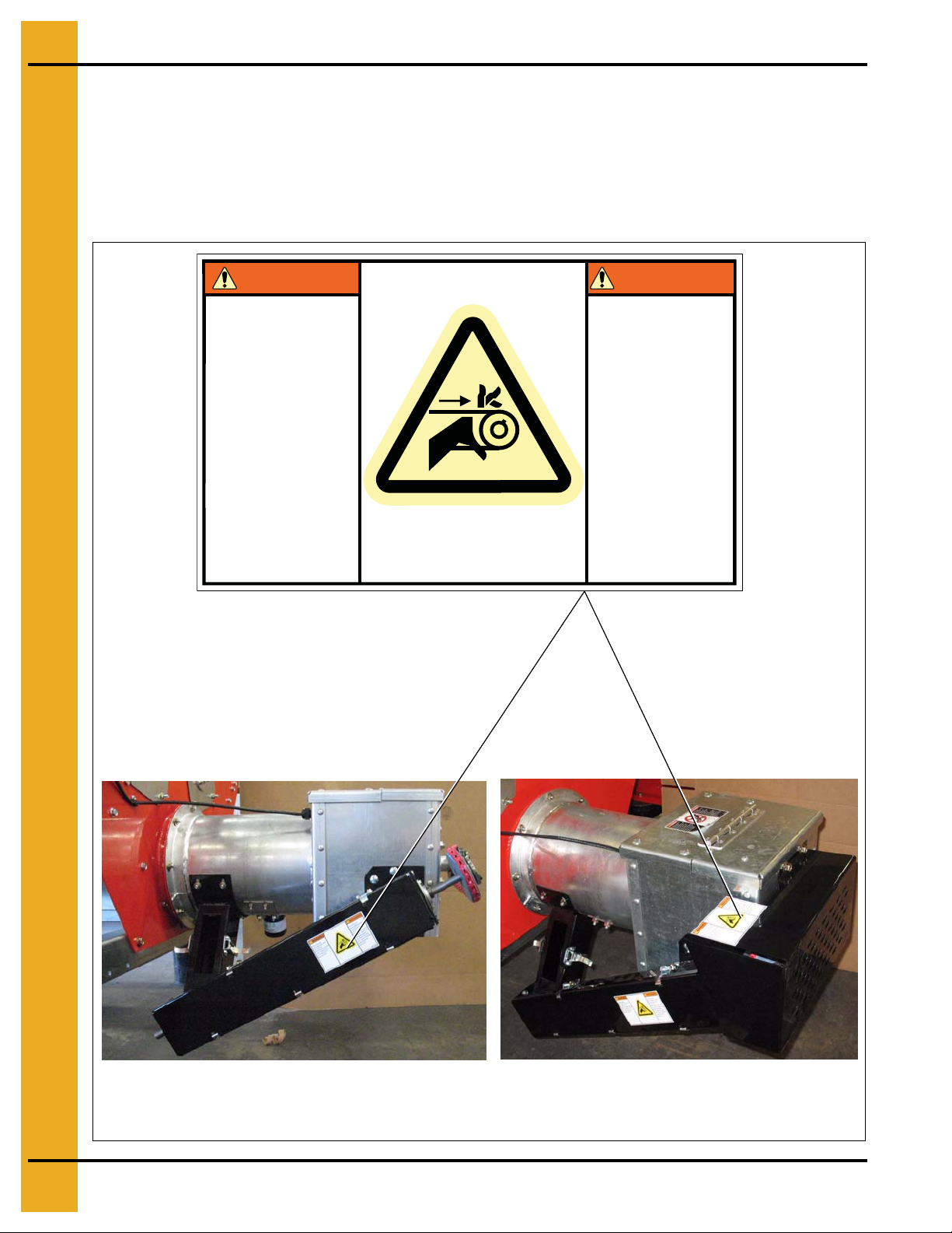
WARNING
Automatically controlled
belt drive can start at
anytime. Keep hands
clear. Failure to do so
could result in serious
injury.
Decal DC-1944
Decal DC-1944 is located on the bottom auger belt guard
and the front bearing plate (which is visible when the bottom
auger belt guard is removed). An alternate location would be
at the rear of the dryer for portable dryers equipped with the
Front Discharge Option.
AVERTISSEMENT
La conduite
automatiquement
contrôlée de la courroie
peut démarrer à tout
moment. Gardez les
mains éloignées.
L’omission de faire ceci
pourra résulter à de
sérieuses blessures.
DC-1944
6 PNEG-1283 Moisture Sampler
Page 7
Installation Instructions for Dryers Made before September 2002
4. Installation
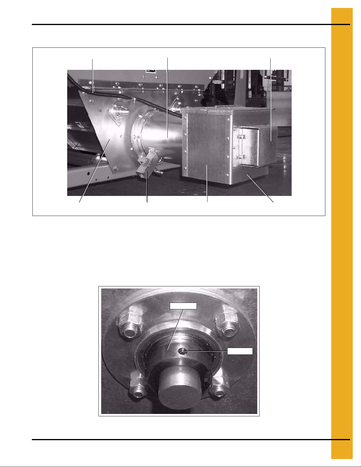
Discharge switch conduit
Unload auger bearing plate
Auger tube
Standard grain sampler
Figure 4A
Discharge side panel
Auger bearing shield
Discharge box bearing plate
1. Remove the auger bearing shield. (See Figure 4A.)
2. Remove the lock collar from the auger shaft. (See Figure 4B.) To remove the lock collar loosen the
set screw and then locate the dimpled hole on the side of the lock collar. Using a hammer and
punch, set the punch in the dimpled hole and hit it in a clockwise direction until the lock collar is
freed from the bearing.
Lock collar
Set screw
Figure 4B
PNEG-1283 Moisture Sampler 7
Page 8

4. Installation
3. Disconnect the tilt switch and remove conduit from the discharge box. (See Figure 4C.)
Tilt switch
Figure 4C
4. Remove the discharge box assembly from the dryer by removing eight (8) 5/16" bolts, then sliding
the discharge box off the discharge auger.
5. Remove the standard grain sampler from the discharge box assembly auger tube.
6. Hold the Moisture Sampler assembly up to the side of the discharge box assembly. Square the
drive end of the Moisture Sampler with the overlapping edge of the discharge bearing plate and
the bottom edge of the discharge side panel. (See Figure 4D.) Mark the location of the three (3)
bolt holes.
Discharge bearing plate
Discharge side panel
Square up here
Figure 4D
7. On the discharge side plate at the drive end of the Moisture Sampler drill three (3) 3/8" holes at the
marks made in Step 6.
8. Using a sheet of paper make a template of the back side of the mounting plate on the drive end of
the Moisture Sampler. Use this template to mark the square hole in the discharge side panel.
Including the three (3) bolt holes in the template will help to ensure correct hole alignment.
9. Cut out the square hole marked out in Step 8.
8 PNEG-1283 Moisture Sampler
Page 9

4. Installation
10. Now put the Moisture Sampler assembly up to the discharge box again and put in the 5/16" bolts
and nuts and tighten just enough to firmly hold Moisture Sampler in place. Use a marker and mark
the four (4) holes at the sensor end of the assembly as shown in Figure 4E. Also mark the square
hole inside the sample tube as shown in Figure 4E.
Mark and cut square hole
Mark and drill holes with a
5/16" drill bit
Figure 4E
11. Remove the Moisture Sampler again and drill the four (4) bolt holes at the sensor end with a 3/8"
drill bit and cut out the square hole marked out in Step 10.
PNEG-1283 Moisture Sampler 9
Page 10

4. Installation
12. Install Moisture Sampler discharge cover (D01-2305-8) in top two (2) holes drilled in the box end
using 5/16" bolt (S-6606). (See Figure 4F.)
Moisture sampler discharge cover
Figure 4F
13. Now install the Moisture Sampler over the two (2) bolts used to install the Moisture Sampler
discharge cover in Step 12 and install remaining 5/16" bolt (S-6606) and n uts (S-3611) in the bottom
hole (do not tighten hardware yet). Attach the sensor end using 5/16" bolts (S-8135) and nuts
(S-3611) making sure that the heads of the bolts are on the inside of the discharge box tube. Now
tighten all seven (7) bolts attaching the Moisture Sampler.
14. Remove the four (4) bolts and lock nuts that hold the auger bearing and flangette the discharge box
bearing plate. Flip the auger bearing so that the outside is now the inside, then re-install bearing
flangette and hardware.
15. Before re-installing the discharge box slide the bearing lock collar onto the auger shaft with the
locking side of the collar facing the rear end of the auger shaft.
16. Now slide the discharge box/Moisture Sampler assembly over the auger and re-attach to the
discharge bearing plate on the dryer.
17. Engage the lock collar with the auger bearing and with a hammer and punch strike it in a clockwise
direction to set it with the bearing, then tighten set screw.
10 PNEG-1283 Moisture Sampler
Page 11

Flangette
4. Installation
Auger shaft
Lock collar
Bearing
Discharge box
bearing plate
Figure 4G
18. Install sheave (018-1047-2) and bushing (D32-0016) on the bottom auger shaft that extends
through the discharge box. The key that comes with the bushing is not needed fo r this installation.
Slide bushing into the sheave (leave loose, do not force the bushing in). Slide sheave and bushing
onto the auger shaft. Insert bushing bolts through the non-threaded holes of the bushing (thread ed
holes are for bushing removal) and thread into the holes of the sheave. Tighten bolts evenly until
bushing is snug against the auger shaft but still loose enough to slide on auger shaft so that its
position can be adjusted in a later step.
Figure 4H
PNEG-1283 Moisture Sampler 11
Page 12

4. Installation
19. To install the Moisture Sampler drive belt, loop the belt over one of the sheaves and the stretch it
over the other one. Belt direction is marked with an arrow on belt. If necessary remove any belt
links. After the belt is installed the sheave on the auger shaft can be adjusted forward or back for
proper belt alignment. The slot in the end plate can be used t o tension the belt. When eve rything is
aligned tighten the auger shaft sheave and any other hardware left loose.
Figure 4I
20. Install the belt guard using four (4) 3/8" bolts (S-7927) and nuts (S-968).
Bolt locations for belt guard
4 ea. 3/8"-16 x 1" bolt (S-7927)
4 ea. 3/8"-16 nut (S-968)
Figure 4J
12 PNEG-1283 Moisture Sampler
Page 13

4. Installation
Installation Instructions for Dryers with New Discharge Box Assembly
Moisture sampler
cover plate (D01-1885)
Standard grain sampler
Moisture sampler tube
cover plate (D01-1886)
Figure 4K
1. Remove the Moisture Sampler tube cover plate (D01-1886). (See Figure 4K.)
2. Remove the Moisture Sampler cover plate (D01-1885). (See Figure 4K.)
3. Install the Moisture Sampler using three (3) 5/16" bolts (S-8135) and nuts (S-3611) on the drive end
and four (4) 5/16" bolts (S-8135) nuts (S-3611) on the sensor end making sure the heads of the
bolts are on the inside of the auger tube.
PNEG-1283 Moisture Sampler 13
Page 14

4. Installation
Sensor end
4 ea. 5/16"-18 x 1-1/4" bolt (S-8135)
4 ea. 5/16"-18 nut (S-3611)
Figure 4L
4. Complete Steps 18-20 starting on Page 11.
Drive end
3 ea. 5/16"-18 x 1-1/4" bolt (S-8135)
3 ea. 5/16"-18 nut (S-3611)
14 PNEG-1283 Moisture Sampler
Page 15

NOTES
PNEG-1283 Moisture Sampler 15
Page 16

5. Parts List
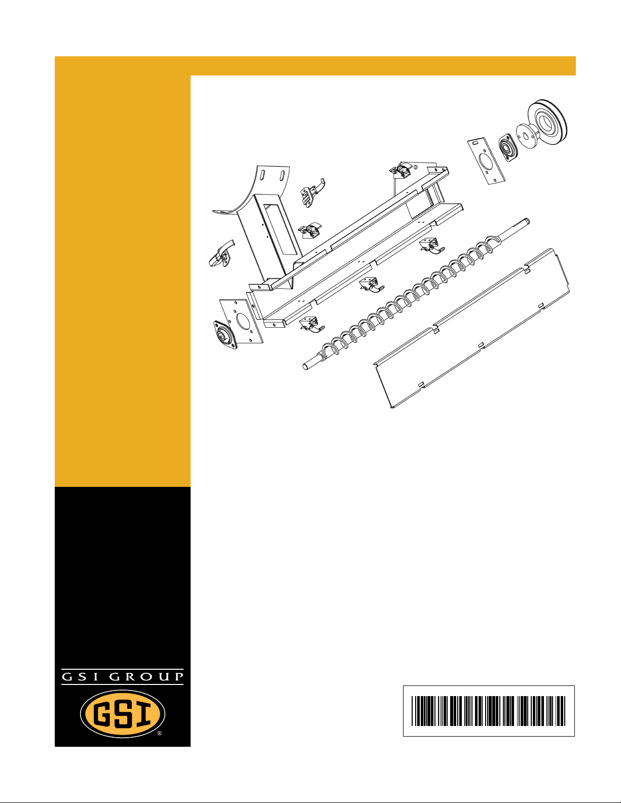
Moisture Sampler
11
13
9
12
4
16 PNEG-1283 Moisture Sampler
Page 17

5. Parts List
Moisture Sampler Parts List
Ref # Part # Description Qty
1 017-1451-8 Sheave, AK46H 4.2 PD 1
2 D03-0845 Bearing, Spherical Flange Mounted 5/8" 2
3 D04-0530 Moisture Sampling Auger Assembly 1
4 D01-1888 Moisture Sampler Belt Guard 1
5 D01-1944-8 Moisture Sampler Weldment IV 1
6 D01-1871 Moisture Sampler End Plate Three (3) Hole 1
7 D01-2337 Moisture Sampler Lid III 1
8 D01-2338 Moisture Sampler III End Plate Two (2) Hole 1
9 FH-4429-1 Latch, Control Box 5
10 FH-5536 Bushing, 5/8" Bore Browning H 019-1040-5 1
11 018-1047-2 Sheave, AK32H 1
12 D01-2305-8 Moisture Sampler Discharge Cover 2008 1
13 D32-0016 Busing, H 1-1/2" Split Taper 1
14 S-2041 Split Lock Washer, 1/4" ZN 9
15 S-1101 Bolt, HHCS 1/4"-20 x 1/2" ZN Grade 2 5
16 S-1102 Hex Nut 1/4"-20 ZN Grade 2 9
17 S-1429 Bolt, HHCS 1/4"-20 x 3/4" ZN Grade 2 4
18 S-8426 Square Key, 3/16" x 1" Long 1
19 S-8472 Screw, TCSF #8-32 x 3/8" HWHS ZN 14
20 S-3611 Flanges Nut 5/16"-18 YDP Grade 2 5
21 S-4276 Bolt, HHCS 5/16"-18 x 1-1/4" ZN Grade 5 5
22 3FH1201 Latch, Tension, Reg. Base. Zinc 2
N/A DC-1944 Decal, Belt Drive Warning, CE, CSA Harm 2
N/A D03-0861 V-Belt, 4L 280 3'
N/A PNEG-1283 Moisture Sampler Installation Manual 1
PNEG-1283 Moisture Sampler 17
Page 18

6. Assembly Instructions
Moisture Sampler Assembly (D04-0550)
See Page 19 for additional details.
Ref # Part # Description Qty
1 D01-1944-8 Moisture Sampler Weldment IV 1
2 FH-4429-1 Latch, Control Box 5
3 D01-2337 Moisture Sample Lid III 1
4 D01-2338 Moisture Sampler III End Plate Two (2) Hole 1
5 D01-1871 Moisture Sampler End Plate Three (3) Hole 1
6 D04-0530 Moisture Sampling Auger Assembly 1
7 D03-0845 Self-Aligning Bearing, 5/8" I.D. 2
8 FH-5536 Bushing, 5/8" Bore Browning H 019-1040-5 1
9 3FH1201 Latch-Tension, Reg. Base. Zinc 2
10 017-1451-8 Sheave, AK46H 4.2 PD 1
2. D01-1888 Belt guard to be included but not shown.
3. HDW-1945-8 Moisture Sampler hardware to be included but not shown.
4. S-8426 to be placed in slot between shaft on D04-0530 and FH-5536.
5. S-8472 (14) to fasten FH-4429-1 and 3FH1201 latches to D01-1944-8.
6. Place S-4276 (5) and S-3611 (5) in FH-4429-1 latches.
7. S-1101 (5), S-2041 (5) and S-1102 (5) to fasten D01-2338 and D01-1871 to D01-1944-8.
8. S-1429 (4), S-2041 (4) and S-1102 (4) to fasten D03-0845 bearings to D01-2338 and D01-1871.
NOTE: 1. DC-1944 to be placed on top of D01-1944-8.
18 PNEG-1283 Moisture Sampler
Page 19

6. Assembly Instructions
Moisture Sampler Assembly (D04-0550) (Continued)
Ref # Part # Description Qty
1 D01-1944-8 Moisture Sampler Weldment IV 1
2 FH-4429-1 Latch, Control Box 5
3 D01-2337 Moisture Sample Lid III 1
4 D01-2338 Moisture Sampler III End Plate Two (2) Hole 1
5 D01-1871 Moisture Sampler End Plate Three (3) Hole 1
6 D04-0530 Moisture Sampling Auger Assembly 1
7 D03-0845 Self-Aligning Bearing, 5/8" I.D. 2
8 FH-5536 Bushing, 5/8" Bore Browning H 019-1040-5 1
9 3FH1201 Latch-Tension, Reg. Base. Zinc 2
10 017-1451-8 Sheave, AK46H 4.2 PD 1
PNEG-1283 Moisture Sampler 19
Page 20

6. Assembly Instructions
Moisture Sampler Update Kit (D04-0532) Assembly Instructions
To replace parts used on the D01-1945-8 Moisture Sampler assembly - Sold from 1/1/07 to 7/1/09
1. Begin by removing the belt guard, belt, Moisture Sampler lid, end plates, bearings, sampler auger,
and sheave, along with any associated hardware.
2. Assemble the bearings (D03-0845) to the end plates (D01-1871 and D01-2338) with the 1/4" bolts,
lock washers and nuts.
3. Mount the three (3) hole end plate (D01-1871) to the bottom of the Moisture Sampler body with the
1/4" bolts, lock washers, and nuts.
4. Insert the sampling auger (D04-0530) into the bearing on the three (3) hole end plate.
5. Insert the shaft at the top of the auger into the bearing on the two (2) hole plate (D01-2338) and
mount the plate to the Moisture Sampler body. Ensure that the slot in the two (2) hole plate is
closest to the discharge box.
6. Insert the shaft at the top of the auger into the split taper bushing (FH-5536) and place the square
key in the slot for both parts. Attach the sheave (017-1451-8) to the bushing with the bushing bolts.
Tightening these bolts will position the bushing and sheave on the auger shaft. Position such that
the sheave center is aligned with the unload auger pulley.
7. The belt is installed on the unload auger pulley and rolled onto the sheave. This belt can be
tensioned by tightening the bolt in the slot on the two (2) hole plate in the desired position. Ensure
that the belt is stretched tight.
8. Latch the lid (D01-2337) onto the Moisture Sampler body.
9. Drill two (2) 3/8" holes at a position 1" below the bottom g uard holes in the discharge box. Assemble
the belt guard (D01-1888) to the discharge box using the current top holes and the newly drilled
bottom holes.
20 PNEG-1283 Moisture Sampler
Page 21

7. Warranty
GSI Group, LLC Limited Warranty
The GSI Group, LLC (“GSI”) warrants products which it manufactures to be free of defects in materials and workmanship
under normal usage and conditions for a period of 12 months after sale to the original end-user or if a foreign sale,
14 months from arrival at port of discharge, whichever is earlier. The end-user’s sole remedy (and GSI’s only obligation)
is to repair or replace, at GSI’s option and expense, products that in GSI’s judgment, contain a material defect in materials
or workmanship. Expenses incurred by or on behalf of the end-user without prior written authorization from the GSI
Warranty Group shall be the sole responsibility of the end-user.
Warranty Extensions:
The Limited Warranty period is extended for the following products:
Product Warranty Period
Performer Series Direct Drive Fan Motor 3 Years
AP Fans and Flooring
Cumberland
Feeding/Watering
Systems
Grain Systems Grain Bin Structural Design 5 Years
Grain Systems
Farm Fans
Zimmerman
All Fiberglass Housings Lifetime
All Fiberglass Propellers Lifetime
Feeder System Pan Assemblies 5 Years **
Feed Tubes (1-3/4" and 2.00") 10 Years *
Centerless Augers 10 Years *
Watering Nipples 10 Years *
Portable and Tower Dryers 2 Years
Portable and Tower Dryer Frames and
Internal Infrastructure †
5 Years
* Warranty prorated from list price:
0 to 3 years - no cost to end-user
3 to 5 years - end-user pays 25%
5 to 7 years - end-user pays 50%
7 to 10 years - end-user pays 75%
** Warranty prorated from list price:
0 to 3 years - no cost to end-user
3 to 5 years - end-user pays 50%
† Motors, burner components
and moving parts not included.
Portable dryer screens included.
Tower dryer screens not included.
GSI further warrants that the portable and tower dryer frame and basket, excluding all auger and auger drive
components, shall be free from defects in materials for a period of time beginning on the twelfth (12
the date of purchase and continuing until the sixtieth (60
th
) month from the date of purchase (extended warranty period).
th
) month from
During the extended warranty period, GSI will replace the frame or basket components that prove to be defective
under normal conditions of use without charge, excluding the labor, transportation, and/or shipping costs incurred in
the performance of this extended warranty.
Conditions and Limitations:
THERE ARE NO WARRANTIES THAT EXTEND BEYOND THE LIMITED WARRANTY DESCRIPTION SET FORTH
ABOVE. SPECIFICALLY, GSI MAKES NO FURTHER WARRANTY OF ANY KIND, EXPRESS OR IMPLIED,
INCLUDING, WITHOUT LIMITATION, WARRANTIES OF MERCHANTABILITY OR FITNESS FOR A PARTICULAR
PURPOSE OR USE IN CONNECTION WITH: (I) PRODUCT MANUFACTURED OR SOLD BY GSI OR (II) ANY
ADVICE, INSTRUCTION, RECOMMENDATION OR SUGGESTION PROVIDED BY AN AGENT, REPRESENTATIVE
OR EMPLOYEE OF GSI REGARDING OR RELATED TO THE CONFIGURATION, INSTALLATION, LAYOUT,
SUITABILITY FOR A PARTICULAR PURPOSE, OR DESIGN OF SUCH PRODUCTS.
GSI shall not be liable for any direct, indirect, incidental or consequential damages, including, without limitation, loss of
anticipated profits or benefits. The sole and exclusive remedy is set forth in the Limited Warranty, which shall not exceed
the amount paid for the product purchased. This warranty is not transferable and applies only to the original end-user.
GSI shall have no obligation or responsibility for any representations or warranties made by or on behalf of any dealer,
agent or distributor.
GSI assumes no responsibility for claims resulting from construction defects or unauthorized modifications to products
which it manufactured. Modifications to products not specifically delineated in the manual accompanying the equipment
at initial sale will void the Limited Warranty.
This Limited Warranty shall not extend to products or parts which have been damaged by negligent use, misuse, alteration,
accident or which have been improperly/inadequately maintained. This Limited Warranty extends solely to products
manufactured by GSI.
Prior to installation, the end-user has the responsibility to comply with federal, state and local codes which apply to the location
and installation of products manufactured or sold by GSI.
9101239_1_CR_rev7.DOC (revised July 2009)
PNEG-1283 Moisture Sampler 21
Page 22

This equipment shall be installed in accordance with
the current installation codes and applicable
regulations which should be carefully followed in all
cases. Authorities having jurisdiction should be
consulted before installations are made.
Copyright © 2009 by GSI Group
Printed in the USA
GSI Group
1004 E. Illinois St.
Assumption, IL 62510-0020
Phone: 1-217-226-4421
Fax: 1-217-226-4420
www.gsiag.com
 Loading...