

Page 1
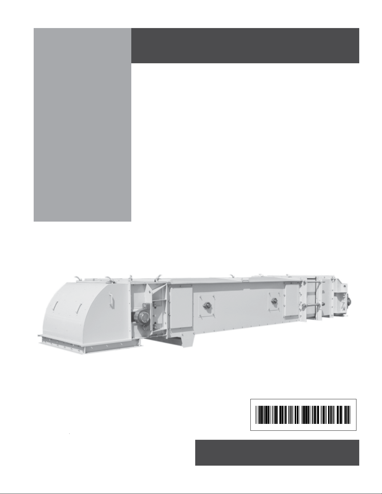
Enclosed Belt
Conveyor
Installation and Operation Manual
PNEG-1204
DATE: 10-16-06
PNEG-1204
Page 2

Introduction
READ THIS MANUAL carefully to learn how to
properly use and install equipment. Failure to do
so could result in personal injury or equipment
damage. This manual and safety signs on your
equipment may be available in other languages.
(Consult with your dealer to see what is available)
INSPECT the shipment immediately upon arrival.
The Customer is responsible for ensuring that all
quantities are correct. Report any damage or
shortages by recording a detailed description on
the Bill of Lading to justify the Customer’s claim
from the Transport Firm. Our responsibility for
damage to the equipment ends with acceptance
by the delivering carrier. Save all paperwork and
documentation furnished with any of the enclosed
belt conveyor components.
THIS MANUAL SHOULD BE CONSIDERED a
permanent part of your equipment and should be
easily accessible when needed.
WARRANTY is provided as part of the company’s
support program for customers who use and
maintain their equipment as described in the
manual. The warranty is explained on the warranty page located on the inside back cover of
this manual.
This warranty provides you the assurance that the
company will back its products where defects
appear within the warranty period. In some circumstances, the company also provides field
improvements, often without charge to the customer, even if the product is out of warranty.
Should the equipment be abused, or modified to
change its performance beyond the factory specifications, the warranty will become void and field
improvements may be denied.
i
Page 3

Use of the Equipment Information page will help you identify your equipment in the case that you need to
call your dealer or installer. This information should be filled out and kept on record.
Equipment Information
Model Number:__________________________
Serial Number:___________________________
Material Handling
1004 East Illinois Street
Assumption, Illinois 62510 USA
Phone: (217) 226-4421
FAX: (888) 741-3004
e-mail: gsi@grainsystems.com
Date Purchased:____________________
Dealer/Distributor Name and Phone Number:
ii
Page 4

Table of Contents
Introduction.....................................................................................i
Equipment Information ...................................................................ii
Safety Guidelines...........................................................................1
Safety ............................................................................................2
Safety Decal Locations. .................................................................5
Overview ........................................................................................9
Intermediate Section Installation .....................................................10
Cover Installation............................................................................12
Loader Installation ..........................................................................13
Motor & T orque Arm II Reducer Installation......................................14
Reducer ....................................................................................15
T orque Arm................................................................................16
T orque Arm Bracket...................................................................1 6
Motor Mount Brackets ...............................................................17
Motor Mount Adjustment Plate ...................................................17
Rear Guard ...............................................................................17
Sheaves and Belts ....................................................................18
V-Belt Adjustment ......................................................................18
Front Guard ...............................................................................19
Reducer Lubrication ..................................................................19
Finding Belt Center Line.................................................................19
Squaring the Belt End ....................................................................20
Check Belt Squareness .................................................................20
Installation of Belt ...........................................................................21
Splicing Belt...................................................................................22
Belt T ension ...................................................................................26
Belt Tracking..................................................................................27
Spouting.........................................................................................30
Spouting Location ..........................................................................31
Belt Conveyor Loading...................................................................32
Motion Sensor Option ....................................................................33
Pressure Plug Switch Option..........................................................34
Starting Conveyor...........................................................................35
Care & Maintenance ......................................................................36
Troubleshooting..............................................................................37
T orque Arm II Appendix...................................................................38
Imperial Bearings Appendix ...........................................................49
All information, illustrations, photos, and specifications in this manual
are based on the latest information available at the time of publication.
The right is reserved to make changes at any time without notice.
iii
Page 5

NOTES
iv
Page 6

Safety
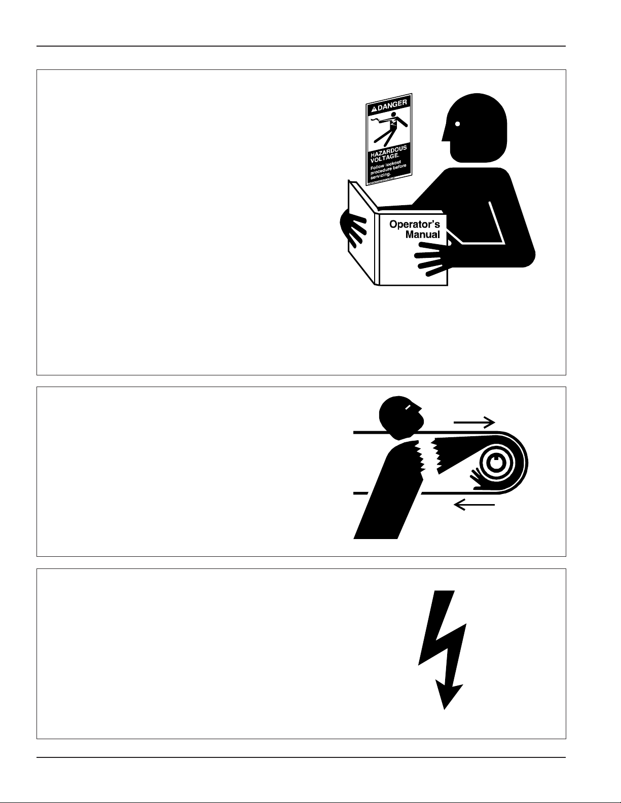
SAFETY GUIDELINES
This manual contains information that is important for you, the owner/operator , to know and
understand. This information relates to protecting personal safety and preventing equipment
problems. It is the responsibility of the owner/operator to inform anyone operating or working in
the area of this equipment of these safety guidelines. To help you recognize this information, we
use the symbols that are defined below. Please read the manual and p ay attention to these
sections. Failure to read this manual and it’s safety instructions is a misuse of the equipment and
may lead to serious injury or death.
This is the safety alert symbol. It is used to alert you
to potential personal injury hazards. Obey all
safety messages that follow this symbol to avoid
possible injury or death.
DANGER indicates an imminently hazardous situation
which, if not avoided, will result in death or serious injury .
W ARNING indicates a potentially hazardous situation
which, if not avoided, could result in death or serious injury .
CAUTION indicates a potentially hazardous situation which,
if not avoided, may result in minor or moderate injury .
CAUTION used without the safety alert symbol indicates
a potentially hazardous situation which, if not avoided,
may result in property damage.
NOTE indicates information about the equipment that
you should pay special attention to.
1PNEG-1204 Enclosed Belt Conveyors
Page 7
Safety
FOLLOW SAFETY INSTRUCTIONS
Carefully read all safety messages in this manual
and on your machine safety signs. Keep signs in
good condition. Replace missing or damaged
safety signs. Be sure new equipment components and repair parts include the current safety
signs. Replacement safety signs are available
from the manufacturer.
Learn how to operate the machine and how to
use controls properly . Do not let anyone operate
without instruction.
Keep your machinery in proper working condition. Unauthorized modifications to the machine
may impair the function and/or safety and affect
machine life.
If you do not understand any part of this manual
and need assistance, contact your dealer.
STAY CLEAR OF ROTATING IDLER
Entanglement in rotating idlers can cause serious injury or death.
Keep all shields and covers in place at all times.
Wear close fitting clothing. S top and lock out
power source before making adjustments,
cleaning, or maintaining equipment.
OPERATE MOTOR PROPERLY
Do not operate electric motor equipped units
until motors are properly grounded.
Disconnect power on electrical driven units
before resetting motor overloads.
Do not repetitively stop and start the drive in
order to free a plugged condition. Jogging the
drive in this type of condition can damage the
conveyor and/or drive components.
2
PNEG-1204 Enclosed Belt Conveyors
Page 8
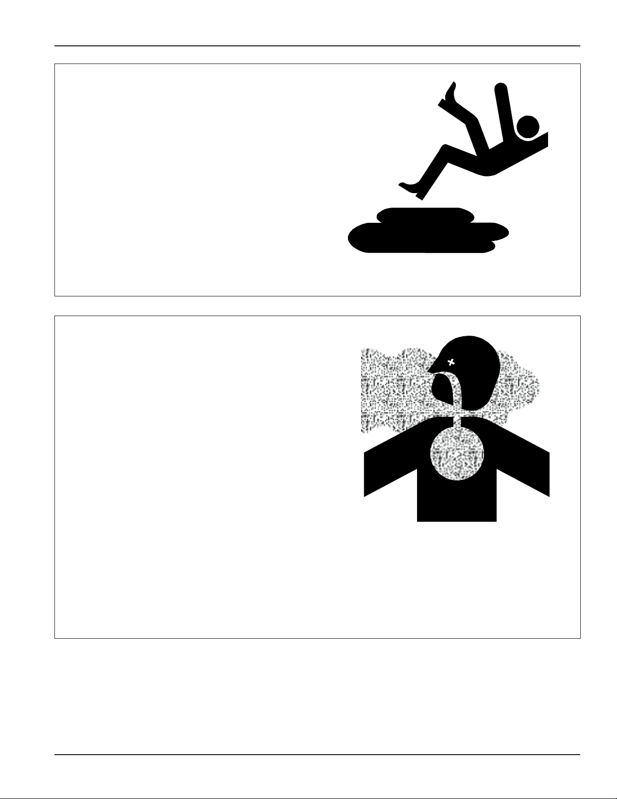
PRACTICE SAFE MAINTENANCE
Understand service procedures before doing
work. Keep area clean and dry .
Never lubricate, service, or adjust machine while
it is in operation. Keep hands, feet, and clothing
from rotating belt and idlers.
Keep all parts in good condition and properly
installed. Fix damage immediately . Replace
worn or broken parts. Remove any build up
grease, oil, or debris.
Safety
REMOVE PAINT BEFORE WELDING OR
HEATING
Avoid potentially toxic fumes and dust.
Hazardous fumes can be generated when paint
is heated by welding, soldering, or using a torch.
Do all work outside or in a well ventilated area.
Dispose of paint and solvent properly.
Remove paint before welding or heating:
• If you sand or grind paint, avoid breathing the
dust. Wear an approved respirator .
• If you use solvent or paint stripper , remove
stripper with soap and water before welding.
Remove solvent or stripper containers and
other flammable material from area. Allow
fumes to disperse at least 15 minutes before
welding or heating.
3PNEG-1204 Enclosed Belt Conveyors
Page 9
Safety
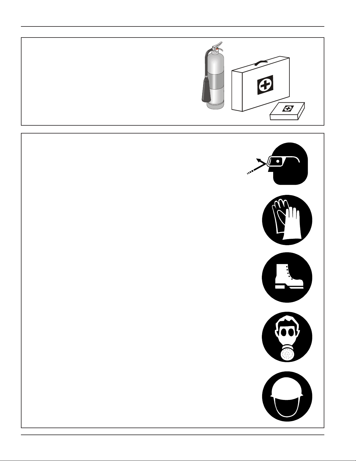
PREPARE FOR EMERGENCIES
Be prepared if fire starts.
Keep a first aid kit and fire extinguisher handy .
Keep emergency numbers for doctors, ambu-
lance service, hospital, and fire department near
your telephone.
WEAR PROTECTIVE CLOTHING
Wear close fitting clothing and safety equipment
appropriate to the job.
Safety glasses should be worn at all times to
protect eyes from debris.
Wear gloves to protect your hands from sharp
edges on plastic or steel parts.
A respirator may be needed to help prevent
breathing potentially toxic fumes and dust.
Wear hard hat and steel toe boots to help
protect your head and toes from falling debris.
Eye Protection
Gloves
Steel Toe
Boots
Respirator
Hard Hat
4
PNEG-1204 Enclosed Belt Conveyors
Page 10

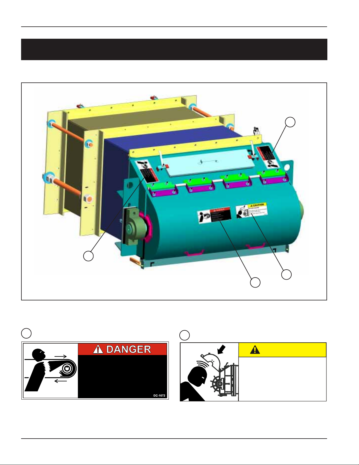
HEAD SECTION DECAL LOCATIONS
Decals
1
1
1
STANDARD HEAD SECTION
1
1
1
1
DC-1672
SNUB HEAD SECTION
ROTATING BELT AND PULLEY WILL
CUT OR ENTANGLE.
KEEP HANDS CLEAR
Disconnect and lockout power before
adjusting or servicing.
Failure to heed will result in
personal injury or death.
5PNEG-1204 Enclosed Belt Conveyors
Page 11
Decals
TAIL SECTION DECAL LOCATIONS
1
1
DC-1672
1
BELT CONVEYOR TAIL SECTION
ROTATING BELT AND PULLEY WILL
CUT OR ENTANGLE.
KEEP HANDS CLEAR
Disconnect and lockout power before
adjusting or servicing.
Failure to heed will result in
personal injury or death.
2
DC-1690
2
1
CAUTION
FALLING HAZARD
Open shroud may fall if unrestrained
and cause bodily injury.
Secure open shroud with chain.
DC-1690
6
PNEG-1204 Enclosed Belt Conveyors
Page 12
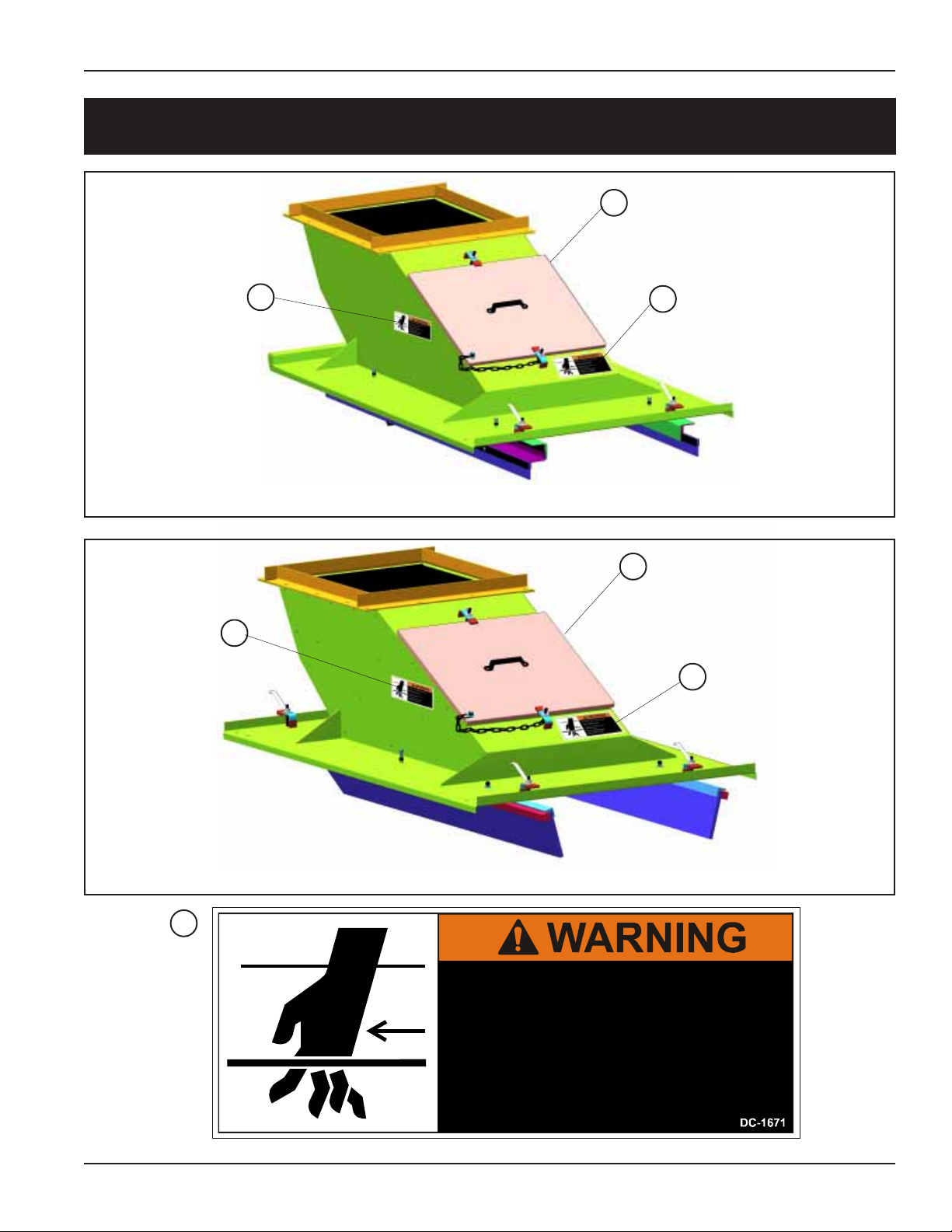
LOADER SECTION DECAL LOCATIONS
Decal On Right Side In
2
Same Location as
Decal on Left Side.
Decals
2
FIXED SKIRT LOADER
2
Decal On Right Side In
2
Same Location as
Decal on Left Side.
2
2
2
DC-1671
SWING-UP SKIRT LOADER
MOVING BELT CAN CUT OR ENTANGLE.
KEEP HANDS CLEAR
Disconnect and lockout power before
adjusting or servicing.
Failure to heed can result in
perso n a l injury or death .
7PNEG-1204 Enclosed Belt Conveyors
Page 13
Decals
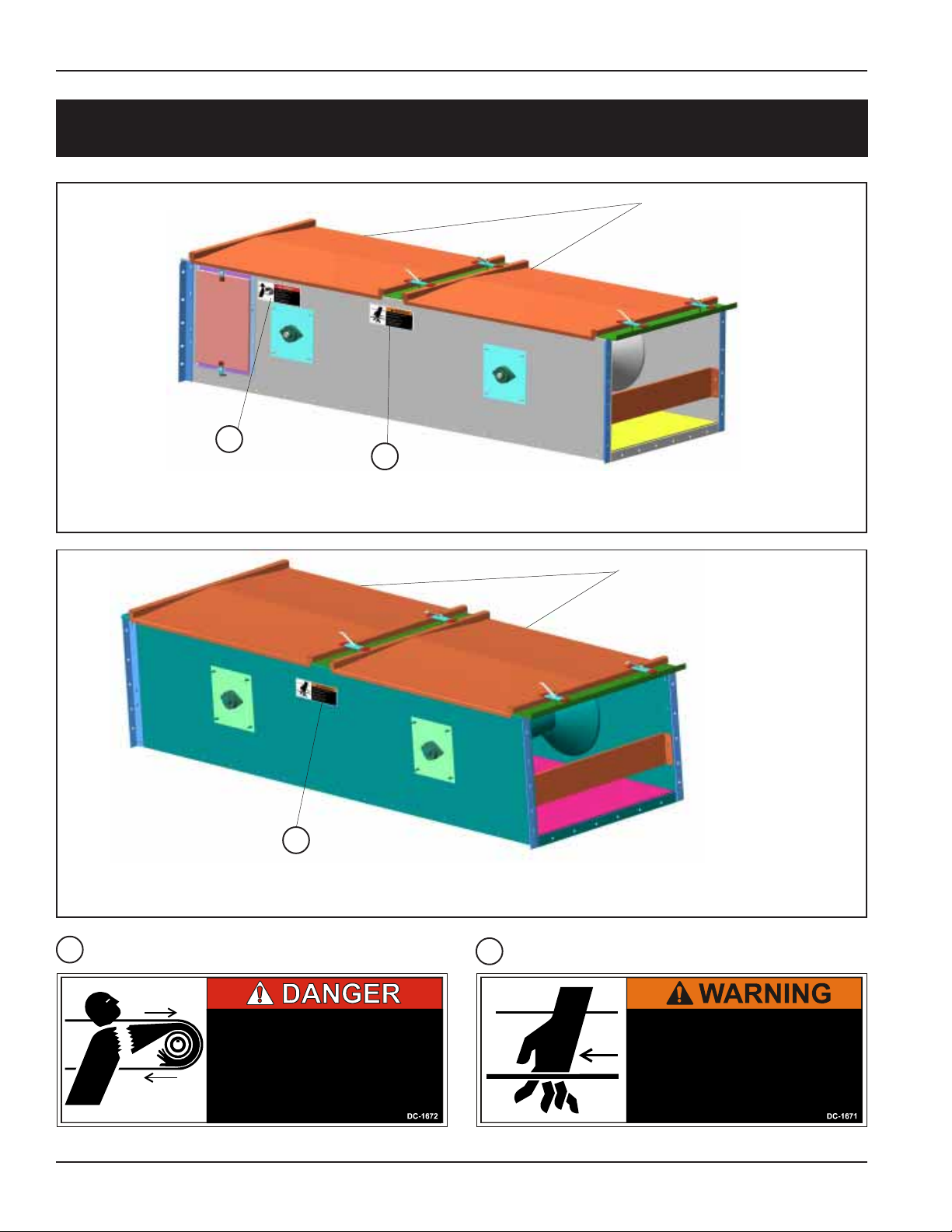
INTERMEDIATE SECTION DECAL LOCATIONS
Decals On Right Side
In Same Location as
Decals on Left Side.
1
2
1
DC-1672
INTERMEDIATE INSPECTION SECTION
2
STANDARD INTERMEDIATE SECTION
2
DC-1671
Decal On Right Side In
Same Location as
Decal on Left Side.
ROTATING BELT AND PULLEY WILL
CUT OR ENTANGLE.
KEEP HANDS CLEAR
Disconnect and lockout power before
adjusting or servicing.
Failure to heed will result in
personal injury or death.
8
PNEG-1204 Enclosed Belt Conveyors
MOVING BELT CAN CUT OR ENTANGLE.
KEEP HANDS CLEAR
Disconnect and lockout power before
adjusting or servicing.
Failure to heed can result in
personal injury or death.
Page 14

Conveyor Assembly
CONVEYOR ASSEMBLY
OVERVIEW
1. Remove any banding and crating material.
Arrange all the conveyor components in such
a fashion that all are easily accessible.
2. Locate sturdy items to serve as blocking (i.e.
wood blocks, saw horses, etc.). Blocking is
used to support the conveyor sections above
the ground to help in assembly . Locate and
place the conveyor sections on the blocking
in order , starting with the head section and
concluding with the tail section.
3. A clearance of at least the width of the
conveyor is recommended on all sides of the
unit. Less clearance may be acceptable
however, serious consideration must be
given to methods of maintenance, removal
and replacement of the conveyor and/or its
parts.
4. The standard conveyor is constructed with
one discharge located at the drive end. If
tripper discharge sections are to be used,
the location(s) must be determined before
continuing with the conveyor assembly . It
may be necessary to position a shorter
intermediate section to serve as a spacer in
order to accommodate the placement of the
tripper discharge(s) where required.
5. Always consult with the approval prints for
exact conveyor layout. Maintain adequate
clearance for tail extension.
6. During installation of the conveyor , string a
chalk line along the conveyor sides to assure
that the conveyor is being assembled in a
straight line. All hardware should be included
with your conveyor. It is recommended that all
flanges be caulked to seal the conveyor to
keep the dust in and the weather out.
7. After all sections are caulked and bolted, the
loader(s) is/are ready to be installed.
Loaders must be installed with the grain
stream moving in the same direction and
same speed as the conveyor belt. (See page
30 for recommended spout loading).
8. After location of the loader(s) (as to spouts,
gates, and valves) has been established, the
loader(s) are bolted to the conveyor . Do not
weld loader(s) to the conveyor . (See page 13
for loader installation).
9. Belt may now be hand fed through the
conveyor. Make sure when splicing belt that
each cut is clean, square and straight.
Detailed belt assembly instructions are listed
on pages 20 - 29. These instructions should
be followed closely and read thoroughly
before starting this step.
10.Check drive belts for tension. Also check the
oil level in the speed reducer. Reducers are
shipped without oil. Refer to page 41 for
the type and quantity of oil. (DO NOT overfill
reducer.)
9PNEG-1204 Enclosed Belt Conveyors
Page 15
Conveyor Assembly
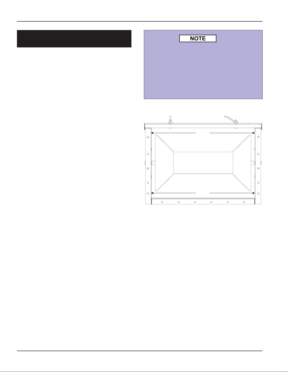
INTERMEDIATE SECTION
INSTALLATION
MAKE SURE TO READ ASSEMBLY
OVERVIEW ON PAGE 9 FIRST.
1. Intermediate sections are supplied in standard ten foot (10') lengths. Depending on
your application and individual specifications
however, shorter sections may be required to
accommodate a desired overall length.
2. After making sure the flanges are aligned,
tighten all hardware on the trough section.
(It is recommended that the flanges are
caulked to insure sealing from dust and
outside moisture.)
It is critical for straitness of the conveyor
that the sides and bottom flanges are
aligned flush. Also, it is important that the
inside dimensions of the box measure
equidistant from side-to-side both top and
bottom of the intermediate section
(Dimension A = Dimension B). See diagram
below.
A
3. During assembly of the intermediate sections, carefully inspect each flange joint to
ensure that the inside bottom and side surfaces of the intermediates are flush. A chalk
line is helpful during this phase of the assembly to ensure the proper alignment of the
intermediate section surfaces. The maximum run-out in any direction should be
+/- 1/4". Make sure the conveyor is level in
horizontal applications.
4. Proceed by attaching the head and tail
assemblies using the same alignment procedures and precautions noted in the preceding
paragraph.
B
End View of Intermediate Section
(Liners not shown for clarity)
10
PNEG-1204 Enclosed Belt Conveyors
Page 16
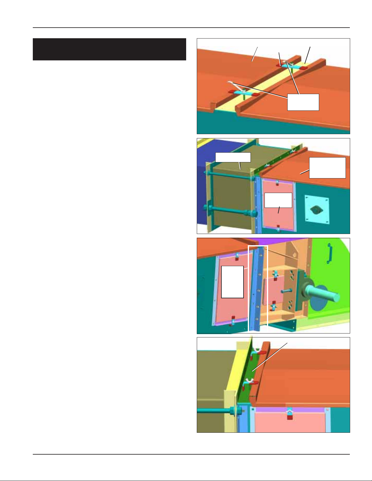
Conveyor Assembly
INTERMEDIATE SECTION
INSTALLATION (CONT.)
1. Intermediate Sections bolt together along the
side and bottom flanges. The covers are
fastened to the cover channels by flat clips
and easy grip handles.
2. St andard intermediate sections do not have
a direction in which they bolt to other
intermediate sections. The cover channels
connect intermediate sections on both ends.
3. T wo inspection intermediate sections are
included on each installation. They should be
assembled at the head and tail. The
inspection holes should be oriented closest
to the head or tail.
4. The inspection door end of each
intermediate section has adapter angles
with slotted holes for bolting to head or
tail sections.
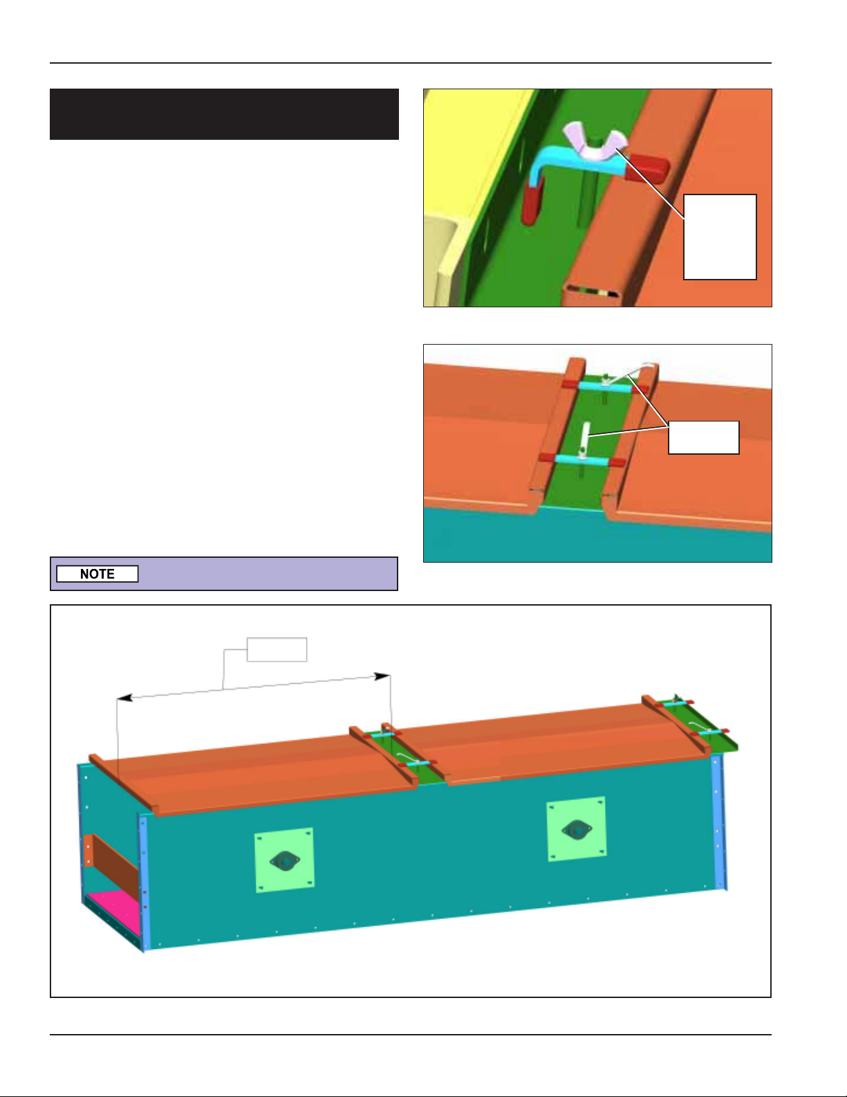
Tail Section
Cover
Flat
Clips
Inspection
Door
Cover Channel
Easy Grip
Handles
Intermediate
Inspection
Section
5. A special cover channel is provided with the
tail as shown at right.
Adapter
Angle
with
Slotted
Holes
Tail Cover Channel
11PNEG-1204 Enclosed Belt Conveyors
Page 17
Conveyor Assembly
COVER INSTALLATION
1. Fasten covers to the belt conveyor with the
3/8" easy grip handles provided. Adequately
tighten the 3/8" handles so that the covers
are in tight contact with conveyor cross
channels.
2. When a loader is on the conveyor, the cover
section may have to be cut accordingly to
accommodate the loader . For installation of
a loader, see Loader Inst allation on page 13.
3. Conveyor covers are made to fit over the
entire width and half the length of a conveyor
intermediate section. Standard covers measure approximately 4' 7" in length. When a
loader is ordered, the cover may be measured and cut to take up the displacement of
the loader housing. This depends on the
position of the loader.
3/8" Wing
Nut on Tail
Section to
Secure
Cover.
Easy Grip
Handles
DO NOT Walk on Conveyor Covers!
4' 7"
12
Standard Cover Length
PNEG-1204 Enclosed Belt Conveyors
Page 18
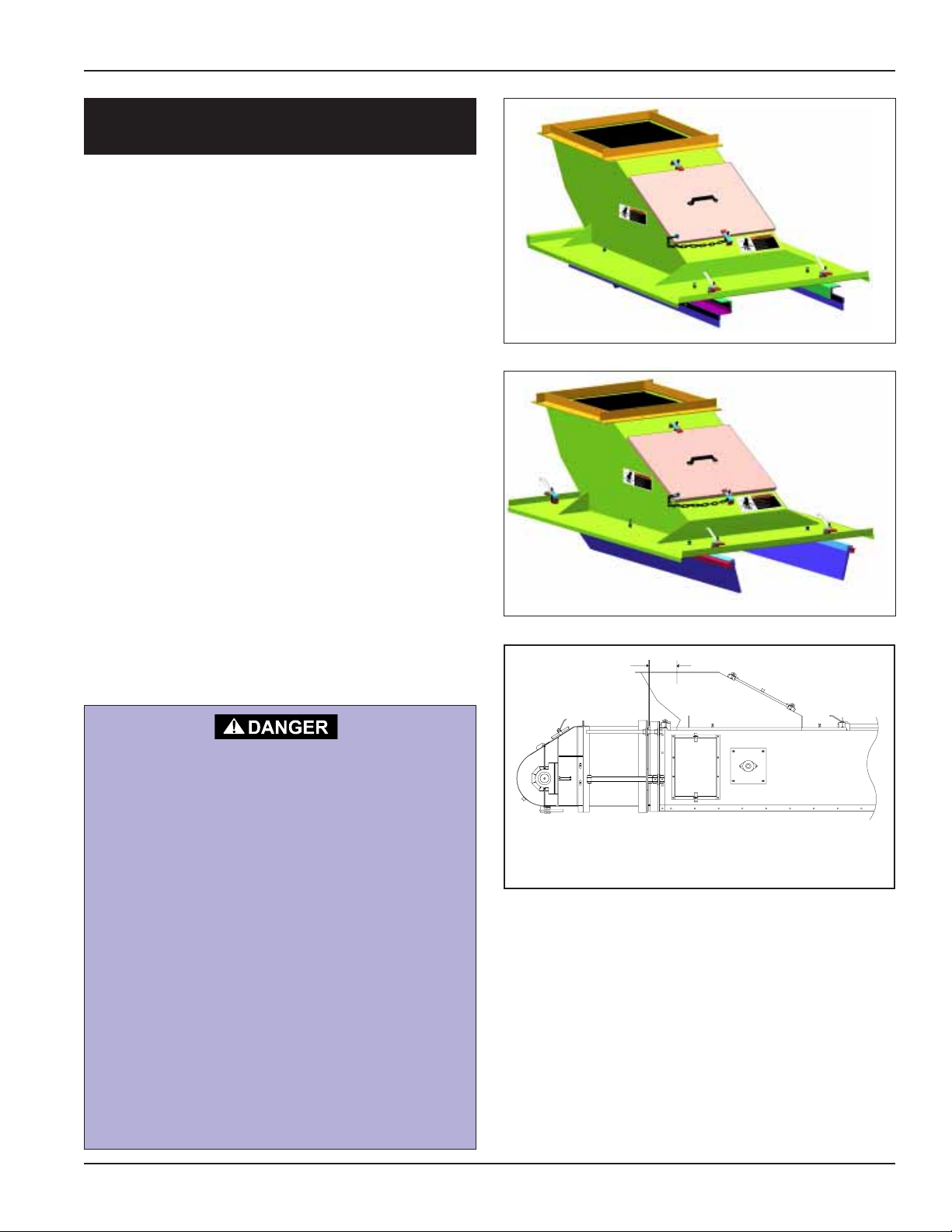
LOADER INSTALLATION
Fixed Skirt Loader
1. The fixed skirt loader always attaches at the
tail end so no cover modifications should be
necessary . The soft rubber skirts are adjustable and can be set to lightly touch the conveyor belt.
Swing-Up Skirt Loader
1. If the loader doesn’t line up exactly with an
intermediate cover, the intermediate covers
will need to be cut to fit. If this is necessary ,
properly position loader and cut a section
from the covers so they will fit between the
cover channel bolted to next section and the
loader flange. Weld cover back together to
achieve required length. Repaint welded
area to prevent rusting.
2. The UHMW swing-up skirts should not touch
the conveyor belt as they can cause wear to
the belt. Use the adjustable set screws to
locate the position of the skirts.
Conveyor Assembly
Fixed Loader
Swing Up Skirt Loader
6"
REMOVE PAINT BEFORE
WELDING OR CUTTING
Avoid hazardous fumes that can be generated
when paint is heated by welding or torching.
Do all work outside or in a well ventilated
area. Dispose of paint and solvent properly.
Remove paint before welding or heating:
• If you sand or grind paint, avoid breathing
the dust. Wear an approved respirator.
• If you use solvent or paint stripper,
remove stripper with soap and water
before welding. Remove solvent or strip
per containers and other flammable
material from area. Allow fumes to
disperse at least 15 minutes before
welding or heating.
GSI’s recommendation for loader installation includes
a minimum distance of no less than 6" between the
center of loader inlet and the tail assembly .
13PNEG-1204 Enclosed Belt Conveyors
Page 19

Motor Assembly
MOTOR AND SHAFT TORQUE ARM II INSTALLATION
Motor
Drive
Pulley
V-Belt
Belt
Guard
Bracket
Belt
Guard
Driven
Pulley
Keep as close
as possible
Hex Nut
Motor Adjustment Plate
Jackscrew
Motor Mount Base Plate
Allow sufficient distance between bushing and
bearing to remove bushing assembly bolts.
Head
Section
Intermediate
Inspection
Section
Torque Arm
Bracket
NOTE: Belt Guards Not
Shown for Clarity .
Head Section
Motor
Torque Arm
Turnbuckle Assembly
Driven
Pulley
Drive Pulley
V-Belt
Hood
Reducer
Drive
14
PNEG-1204 Enclosed Belt Conveyors
Page 20

Motor Assembly
MOTOR AND TORQUE ARM II
REDUCER INSTALLATION
Reducer
1. T o aid in the installation of the reducer onto
the shaft, remove any protective coating film
from the shaft.
2. Place key in the keyway on the drive shaft.
3. Attach inside bushing to the reducer drive.
4. Line up the keyway on reducer with key on
shaft and slide the reducer drive onto the
drive shaft.
5. Slide outside bushing onto shaft and attach
to reducer drive. Once reducer drive is in
place, fully tighten both bushings.
(See page 38 for more details.)
Bushing
Key
Conveyor
Drive
Shaft
Shaft
Mount
Reducer
Conveyor
Drive Shaft
Bushing
Shaft
Mount
Reducer
BELT GUARD
COVER
DC-995
DC-994
DC-994
DC-995
SHEAR POINT
Keep hands clear of moving
parts. Do not operate with
guard removed. Disconnect
and lockout power before
servicing.
WARNING
Shear point. Keep hands
clear of moving parts. Do
not operate with guard
removed. Disconnect
and lockout power before
servicing.
DC-995
DC-994
15PNEG-1204 Enclosed Belt Conveyors
Page 21

Motor Assembly
MOTOR AND TORQUE ARM II
REDUCER INSTALLATION
T orque Arm Turnbuckle Assembly
6. Install the torque arm between the 2 plates
that are located on the bottom of the reducer
drive. Secure using bolt with washer and lock
nuts. Attach the other end to the torque arm
bracket on the conveyor using two bolts,
washers, and locknuts. T ighten the torque arm
by turning the turnbuckle. Adjust the position
of the reducer. The reducer should be in a
vertical position as shown on page 14.
T orque Arm Bracket
(CONT.)
Plates on
Reducer Drive
T orque Arm
7. The torque arm bracket is mounted under the
first intermediate section. Locate bracket by
matching an existing set of holes in the
intermediate side that allows the turnbuckle
assembly to be as short as possible with the
reducer in a vertical position.
The holes in the intermediate side must
be drilled out to 9/16" Diameter. Att ach
with provided hardware.
Torque
Arm
Bracket
Torque
Arm
Bracket
T orque Arm
Assembly
Turnbuckle
T orque Arm
Plates
on
Reducer
Drive
16
Turnbuckle
PNEG-1204 Enclosed Belt Conveyors
Page 22

Motor Assembly
MOTOR AND TORQUE ARM II
REDUCER INSTALLATION
Motor Mount Brackets
8. Remove three bolts from each side of the
reducer housing. Use a set of holes in the
motor mount upright brackets that allows the
motor plate to be as close as possible to the
top of the conveyor. Check this location by
temporarily positioning the belt guard on the
reducer with the hole in the guard centered
over the reducer input shaft. This will show
the correct motor position for the lengths of
v-belts provided. Attach by replacing bolts
through brackets and housing. T ighten bolts
securely.
Motor Mount Adjustment Plates
(CONT.)
Motor
Mount
Bracket
Attached to
Reducer
Nuts
Jackscrews
Motor Mount
Adjustment
Plate
9. Thread nuts onto jackscrews. Place bolt
through motor mount bracket and base plate.
Thread another nut onto jackscrews to
secure. Repeat for 3 remaining jackscrews.
10.Thread another nut onto all four jackscrews.
Place adjustment plate onto jackscrews.
Thread another nut onto each jackscrew to
secure adjustment plate. Use these nuts to
adjust the motor height.
1 1.Attach the motor to the adjustment plate
using bolts and locknuts.
Drive Guard Rear Panel
12.Install the rear panel of the drive guard before
mounting the sheaves. The rear panel has
two (2) mounting brackets with slotted holes.
Attach these left-hand and right-hand belt
guard mounting brackets to the motor mount
frame. Then fasten rear panel of belt guard to
the belt guard brackets. After the rear panel
is in place, install sheaves onto motor and
reducer.
Base
Plate
17PNEG-1204 Enclosed Belt Conveyors
Page 23

Motor Assembly
Sheaves and Belts
13.Assemble the V-belt driven sheave to the
input shaft of the shaft mount reducer . Insert
the bushing into sheave hub. Match holes in
bushing and hub (not threads). Put screws
into holes that are farthest apart. Slip entire
unit with key onto shaft. Align the driver and
driven sheaves and tighten the retaining
screws. During tightening, it is possible for
the sheave to move out of alignment or
become out of square. For maximum V -Belt
life, the driven sheave should remain both
perpendicular to the drive shaft and aligned
with the drive sheave. Slip the V -belts over
both the driver and driven sheaves.
V-Belt Adjustment
Too much tension shortens belt life.
Check belt tension frequently during
the first 24-48 hours of operation.
14.Adjustment of V-belt tension is achieved by
tightening the hex nuts located on the four (4)
jackscrews of the motor base. Adjust motor
base equally at all four jackscrews to
maintain shaft alignment. Belts are
designed to fit loose upon installation. When
the V -belt tension is correct, tighten the top
nut on the jackscrews to lock the motor base
in position. Proper tension is 1/64" of
deflection per one (1") inch of sheave centers
on one side of belt, centered between
sheaves. (See diagram below.)
Sample Deflection Problem:
3-1/2' Span = 21/32" of Deflection (Approximately 11/16")
1. 3-1/2' = 42"
2. 1/64" = .015625"
3. 42" x .015625" = .65625"
4. .65625" = 21/32" of Deflection
18
PNEG-1204 Enclosed Belt Conveyors
Page 24

Front Guard Panel
Belt Width
15.Install the front drive guard panel over the four
corner mounting studs. Secure with washers
and nuts provided.
Belting Assembly
Lubricate Reducer Drive
16.Fill the shaft mount reducer with the
manufacturer’s recommended oil.
(See Page 41.)
Lubricate Bearings
17. Grease bearings on head, tail and idlers.
Lubricate bearings according to bearing
manufacturer’s recommendations.
(See Page 52.)
Grease
Bearing
Housing
Grease Idler
Bearings
FINDING BELT CENTER LINE
1. T o find the belt center line, measure the belt
width at five points. S tarting near the end of
the belt, measure the belt width in 10" intervals, marking them as you measure. Each
measurement shall then be divided in two
and marked. Using a straight edge, draw a
center line using the points as a guide. (See
diagram at right)
Centerline
10” 10” 10” 10”
Center Point of Width Measurements
Belt End
19PNEG-1204 Enclosed Belt Conveyors
Page 25

Belting Assembly
SQUARING THE BELT END
1. A double arc method is used on establishing
a cut line on the belt. After a center line has
been drawn, pick a point on the center line
about two times the belt width. From this
point, strike an arc across the width of the
belt end. A nail may be used as a pivot point
with twine used as the arm of the arc. Tie a
marking tool (chalk, for example) to the end
of the twine.
Pivot Point of
1st Arc
Belt Width
2. A second set of arcs is struck with the pivot
point of the arc on center line and close to
the belt end. Where the two arcs intersect
each other are points on which a cut line is
drawn.
The second arc should be slightly less than
half of the width of the belt.
Intersection
Point
Pivot Point of
2nd Arc
Cut Line
Centerline
CHECK THE SQUARENESS OF
THE BELT CUT
1. T o check for the accuracy of the cut made,
measure lengthwise 50 inches from each
edge of the belt. Using a straight edge, draw
a line diagonally across the belt. This should
be done from the 50 inch point to the end
corner on the opposite side of the belt. Do
the same procedure in reverse to form an “x”.
The intersection point of the two lines of the
“x” should be in line with the center line of the
belt.
Belt
Centerline
Intersection
Point
Diagonal Line
Cut
Edge
of Belt
Intersection
Point
20
PNEG-1204 Enclosed Belt Conveyors
Page 26

Belting Assembly
INSTALLATION OF BELT
1. Hand thread the belt through the conveyor
with the tail section in a retracted position.
Attach a tightening device to each end of the
belt to prevent damage to the belt. Place a
2" x 12" piece of wood width wise on top of
an intermediate section where the belt ends
are to be brought together. Bring the belt
seam together over the 2" x 12" piece of
wood for a working surface to be used for
splicing. (See diagram below.) The belt
splice can now be installed following step-bystep directions on the following four pages.
TAIL
END
2" x 12" Block of Wood
Field cut, square, and
punch holes in field
this end of belt.
Conveyor
Belt Ends
DIRECTION OF BELT TRAVEL
Factory Supplied Splice
Protector (Flipper)
Install Flippers on end belt
that has been pre-punched
and cut by factory.
HEAD
END
Intermediate Section with Covers Removed
Detail installation of belting into conveyor.
Install belting into tail end.
IMPORTANT: Note the direction of the flippers on belt.
Flippers are installed to aid in cleanout of tail shroud.
21PNEG-1204 Enclosed Belt Conveyors
Page 27

Belting Assembly
SPLICING THE BELT
1. Support belt ends with wood plank. Nail
Flexco T emplate in position with belt ends
tight against lugs.
2. Spray template holes with Flexco Silicone
Lubricant. Punch or bore bolt holes. Remove
template.
Splice protector design may vary due to type of
conveyor. I.E. - Reversible conveyors and
conveyors with low-profile head discharges do
not have splice protectors with tails (flippers).
1
2
2
22
PNEG-1204 Enclosed Belt Conveyors
Page 28

Belting Assembly
SPLICING THE BELT
3. T o assemble bottom plate insert 2 bolt s and
attach clip.
4. Fold one belt end back and insert bolts in
one row of holes.
5. Align bolts with template teeth and place the
other belt end over bolts. Remove template.
6. Place top plates over bolts using bolt horn.
(Cont.)
3
4
5
6
23PNEG-1204 Enclosed Belt Conveyors
Page 29

Belting Assembly
SPLICING THE BELT
7. Start nut s on bolts by hand.
8. Cut Flexco-Lok T ape 3-1/2 times the belt
width and feed tape under top plates, under
the bottom plates, then back under top
plates.
9. Pull tape tight and hold in position by tightening a fastener at each end. Then tighten all
other plates.
10.Tighten all nuts uniformly . NOTE: A flexco
Power Wrench used with an impact tool will
speed this step considerably .
(Cont.)
7
8
9
24
10
PNEG-1204 Enclosed Belt Conveyors
Page 30

Belting Assembly
SPLICING THE BELT
1 1.Hammer plates in belt with wood block.
Retighten nuts.
12. Break off excess bolt ends using two bolt
breakers. Peen or grind bolts to finish.
13. Place flippers on belt. The flipper should be
located so the tail of the flipper covers the
splice. Note direction of belt travel. The
flippers are evenly spaced across the belt
with a 1/4" gap between them. There will be a
larger gap between the outside flipper and
the edge of the belt.
14. Punch or bore holes. Att ach flippers using
same connectors as splice. Repeat steps
10-12.
(Cont.)
11
15. Finished splice.
12
13
Direction of
Rotation
25PNEG-1204 Enclosed Belt Conveyors
Page 31

Belting Assembly
BELT TENSION
1. IMPORTANT: The belt tension should be
checked every day of use for the first few
days. Conveyor belts stretch when new and
must be checked at regular intervals. After
approximately two weeks of usage, checks of
belt tension may be done at less frequent
intervals.
2. After splice has been installed and 2" x 12"
piece of wood is removed, belt is ready to be
tightened.
3. The belt is tightened by turning the take-up
rods located on the tail section. Make sure
that they are adjusted equally to prevent
misalignment. The conveyor belt should be
tightened enough to prevent the belt from
slipping on the drive pulley . When done
adjusting take-up rods, tighten nuts against
flanges to lock in place.
After an hour of running, the belt should be
retightened and thereafter checked at
regular intervals. Take-Up Rods are for
tightening belt only. They are not to be
used to adjust belt tracking.
Leveling Rod
Do Not over tighten belt. Over
tightening can cause premature
wear of bearings and shafts.
To tighten
belt tension,
adjust tail
section in this
direction.
Leveling Rod
T ake-Up Rod
Take-Up Rod
Nuts
26
Flanges
TAIL SECTION
PNEG-1204 Enclosed Belt Conveyors
Page 32

BELT TRACKING
Squareness of the Conveyor
1. Before tracking procedure is begun, each
section should be square and straight so
there is no unequal weight distribution. Check
conveyor intermediate sections for any
extensive damage such as cave-in sides,
etc. Idlers should be checked for looseness. If
idlers are loose, re-center and tighten set
screws on bearing lock collar .
2. After intermediate sections are bolted
together , a chalk line should be strung along
the sides of the conveyor, making sure that it
is in a straight line. Loosening bolts on the
intermediate frames will permit slight
adjustment of the intermediate sections.
Belting Assembly
3. After conveyor has been installed, check to
see if the unit is level (width wise). The
conveyor must be level for proper belt
tracking.
Shims
Bearing
Bearing
Adjustment
Bolts
Shims
Bearing
TAIL SECTION HEAD SECTION
27PNEG-1204 Enclosed Belt Conveyors
Page 33

Belting Assembly
Tracking Adjustment
4. Belt tracking adjustment is initiated by moving the bearing adjustment bolts. These are
located on both sides of the head and tail
sections. Belt tracking adjustments are made
by adding or removing shims under bearing
as necessary . DO NOT use take-up rods to
correct belt tracking.
5. Adjustment of the idlers is done by loosening
eight bolts. These bolts hold the bearings in
place and are located on both sides of the
conveyor sections (four on each side). Af ter
loosening these bolts, the end of the idler can
shift either forward or backward.
Bearing
Adjustment
Bolts
Bearing
Adjustment
Bolts
28
Loosen these
four nuts on
both sides for
adjustment.
PNEG-1204 Enclosed Belt Conveyors
Page 34

General Tracking/Training Procedures
Belting Assembly
6. Tracking the belt is a process of adjusting
idlers, pulleys, and loading conditions in a
manner that will correct any tendencies of the
belt to run other than true.
7. A normal sequence of training is to start with
the top pulleys in the direction of belt travel.
St art with the belt empty . After tracking is
completed, run the belt with a full load and
recheck tracking.
8. Tracking adjustment is done while the belt is
running and should be spread over some
length of the conveyor preceding the region
of trouble. The adjustment may not be immediately apparent, so permit the belt to run for
several minutes and at least three full belt
revolutions after each idler adjustment to
determine if additional “tracking” is required.
9. After adjustment, if the belt has overcor-
rected, it should be restored by moving back
the same idler, and not by shif ting additional
idlers or rollers.
13.The basic and primary rule which must be
kept in mind when tracking a conveyor belt is
simple, “THE BELT MOVES TOWARD
THAT END OF THE ROLL/IDLER IT CONTACTS FIRST.”
14.The reader can demonstrate this for himself
very simply by laying a small dowel rod or
round pencil on a flat surface in a skewed
orientation. If a book is now laid across the
dowel rod and gently pushed by one’s finger
in a line directly away from the experimenter,
the book will tend to shift to the left or right
depending upon which end of that dowel rod
the moving book contacts first.
10.If the belt runs to one side at a particular point
or points on the conveyor structure, the cause
will probably be due to the alignment, or
leveling of the structure, or to the idlers and
pulleys immediately preceding that particular
area, or a combination of these factors.
1 1.If a section or sections of the belt run off at all
points along the conveyor , the cause is
possibly in the belt itself, in the belt not being
joined squarely , or in the loading of the belt.
With regard to the belt, this will be due to
camber. It s condition should improve after it
is operated under full load tension. It is a rare
occasion when a cambered belt (less than
1/2%) needs to be replaced.
12.When replacing a used belt, go through the
system and square and level all rollers, idlers,
pulleys and bed before training a new belt.
29PNEG-1204 Enclosed Belt Conveyors
Page 35

Loading
SPOUTING
1. Below are the recommended and incorrect
ways to attach spouting to load the conveyor .
Contact the GSI Material Handling Department if there are any questions about loading
conditions.
RECOMMENDED
Grain Flow
Belt Direction
AVOID
INCORRECT
Grain stream centered on the belt. Grain moving in the
same direction and at the same speed as the belt.
Grain Flow
Belt Direction
This causes excessive wear of belting and off center
loading on belt which causes spillage. This method of
loading results in grain tumbling on belt.
Grain Flow
30
Belt Direction
Grain should be loaded in the same direction
of belt travel and at the same speed.
PNEG-1204 Enclosed Belt Conveyors
Page 36

SPOUTING LOCATION
1. Grain should come out from storage and
make a 90° turn by use of baffles and load
straight into the conveyor at approximately a
45° angle.
Belt Direction
Pit
or
Bin
Loading
Pit or Bin
Belt Direction
SIDE VIEWTOP VIEW
END VIEW
31PNEG-1204 Enclosed Belt Conveyors
Page 37

Loading
BELT CONVEYOR LOADING
1. St art with a light load and gradually work up
to the load that the conveyor was designed to
handle. Check chutes to see that the material
is being directed onto the center of the belt.
Off-center load will affect belt alignment in
that the belt will run off center . A central load
will maintain belt alignment.
2. The loading point of a belt conveyor is the
critical point. Here the conveyor receives its
major abrasion and practically all of its impact. The ideal condition is to have the
material flow onto the belt at the same speed
and direction of travel as the belt, with a
minimum amount of impact, and to load the
belt on center.
CORRECT - Evenly Loaded
3. Adjust the skirts to prevent side spillage of
material and to keep the load central on the
belt. The maximum distance between
skirtboards customarily is two thirds the width
of a trough belt.
4. The skirt lengths are designed to stop side
spillage. The material should also be at rest
on the belt before it reaches the end of the
skirt. If the material is still tumbling as it
passes the skirt end, the skirts should be
lengthened.
INCORRECT - Loaded to One Side
Belt Shift
Spill
EFFECT OF IMPROPER LOADING
32
PNEG-1204 Enclosed Belt Conveyors
Page 38

MOTION SENSOR OPTION
WHIRLIGIG - WG1-4B
Installation Instructions
ALWAYS OBSERVE LOCKOUT AND TAGOUT PROCEDURES BEFORE, DURING
AND AFTER INSTALLA TION.
DO NOT REMOVE THE WHIRLIGIG
COVER. THE ROTATING COMPONENTS
UNDER THE COVER COULD CAUSE
SERIOUS INJURY.
1. Shaft ends are predrilled and tapped from
the factory .
2. Thread the WHIRLIGIG onto the machine
shaft using 5/8" open ended wrench and
suitable thread locking adhesive (Loctite or
similar).
Options
3. Install the sensor to the WHIRLIGIG baseplate. T wo sets of predrilled holes are provided for M800 sensor. Fit the sensor to
leave an approximate 2mm gap between
sensor face and cover.
A universal bracket (WGB18/30) is supplied
for fitting 18mm or 30mm sensors.
4. Connect the sensor in accordance with
manufacturer’s instructions and observe all
relevant electrical & OSHA regulations.
5. Fix the flexible strap securely to the static
structure. (If required).
TIP: The M800 speedswitch and system
function can be tested by placing a thin
metal plate between the sensor and the
cover of the WHIRLIGIG. When installing
other industry standard sensors, leave a
small gap between the sensor & the
WHIRLIGIG cover for this purpose.
M800 Sensor
Cylindrical Sensor
18/30mm Bracket
(Supplied)
10mm Screws (4)
(Supplied)
50mm Screws (4)
(Supplied)
Flexible Conduit
T ap Shaft for 1/2" UNC Centered
Cover
The Whirligig
Monitored Shaft
Flexible Strap
33PNEG-1204 Enclosed Belt Conveyors
Page 39

Options
PRESSURE PLUG
SWITCH OPTION
Monitor MODEL GX, Part No.7-8150 - Neoprene
diaphragm, standard switch
ELECTRICAL INSTALLATION
1. Hazardous Location Precautions
Observe the regulations listed in the National
Electrical Code regarding equipment in
hazardous locations. In particular , insure
power is disconnected whenever the cover is
removed, insure the cover and case mating
surfaces are not damaged, and upon
completion, ensure cover screws are secure
and that no gaskets or sealer has been used
between the cover and case surfaces.
2. Output Contacts
Route wires through the 1/2" NPT conduit
entrance. No power is required to operate
the diaphragm bin monitors. All electrical
installation is done directly to the terminals of
the output switch. The switch terminals are
designated with “3” (COM-common),
“2” (N.C.-normally closed), and “1” (N.O.normally open). When the diaphragm is not
sensing material, the switch is in the normal
condition (i.e. N.C. contact is closed to COM,
and N.O. contact is open to COM). However ,
when the diaphragm senses material, the
switch is opposite from normal condition
(i.e.N.C. contact is open to COM, and N.O.
contact is closed to COM). Be sure to comply
with all electrical specifications listed within
this bulletin.
34
PNEG-1204 Enclosed Belt Conveyors
Page 40

STARTING CONVEYOR
1. Check for and remove any tools or debris
that may have been left in the conveyor
during installation.
2. Tighten the take-up rods on the t ail section
equally . The belt should be tightened sufficiently to prevent slippage between the drive
pulley and belt and to conform to the crown
on the crowned head pulley .
3. Install covers after belt has been trained.
SECURE SHROUD DURING MAINTENANCE
Start-Up
Slot
Shroud
Chain
While accessing the tail pulley, the tail shroud
may either be removed or pivoted in an upright
position. If pivoted upright, then secure the
shroud by placing the chain in the slot as shown.
35PNEG-1204 Enclosed Belt Conveyors
Page 41

Maintenance
CARE & MAINTENANCE
Before any maintenance is performed
to the conveyor, power must be shut
off and locked out to prevent
accidental start up!
Welding
Welding on or to the conveyor may cause damage to both the conveyor and its electrical system. If welding is necessary, precautions should
be taken to protect the conveyor . Should it be
necessary to fasten anything to the conveyor
permanently , careful consideration should be
given to methods of maintenance, removal and
replacement of the conveyor and/or its parts.
Motor
The care and maintenance section is provided with
the intention of helping to extend the useful life of the
unit. Like all equipment, the useful life of the conveyor is greatly reduced if not used wisely and well
maintained.
Please follow the next few simple steps to insure
the safety and longevity of your equipment.
• Check all bearings and moving parts daily
during use.
• Lubricate bearings according to bearing
manufacturer’s recommendations.
(See page 52.)
• Follow manufacturer’s recommendations for
gear reducer lubrication and maintenance.
(See page 41.)
• Inspect the V-belt s periodically for proper
tension and wear. V-belts should be
replaced as necessary. If replacement or
tension adjustment is required, please refer to
the Shaft Mount Reducer Assembly Section
on page 15.
• The belting and belt idlers should be
checked periodically for wear and damage.
Should replacement of these components be
required, contact the manufacturer.
Bearings
Connect the conveyor motor to a power source
according to the motor manufacturer’s instructions and recommendations. To avoid injury it is
recommended that a certified electrician perform
the motor wiring. A shut off switch should be
placed near the motor so that the system may
easily be shut down to help prevent accidents
during maintenance. It is important to check
proper motor shaft rotation before installing drive
belts
Support
Include adequate support for the conveyor assembly to be installed at intervals no greater than
10 feet. It is recommended that supports be
installed at vertical portions of flanges leaving
bottoms of intermediate sections clear. By
attaching supports in this manner, the removable
bottoms are unobstructed for ease of replacement. Support legs are available as an option.
STORAGE
If the unit is to be inactive for an extended period,
the following procedures are recommended.
• Thoroughly clean the unit.
• Loosen the V-belt tension. Doing so
relieves the stress placed on the bearings
and shafts of the drive and tail sections.
Lubricate bearings at regular intervals. If one
bearing is re-lubricated, all other bearings should
also be lubricated. Do not over lubricate as this will
destroy bearing seals.
36
• Lubricate shafts and drive chain
components with a good grade of light
machine oil.
PNEG-1204 Enclosed Belt Conveyors
Page 42

Troubleshooting
TROUBLESHOOTING
SYMPTOM PROBLEM SOLUTION PAGE
Conveying belt drifts
sideways.
Material buildup on
idler pulley , drive pulley
or between sections
and belt.
Belt not properly tracked.
Belt splice not square.
Material not placed on
center of belt.
Machine is not straight.
Machine not level.
Material buildup on
pulleys.
Material getting under
belt.
Track belt over pulleys.
Check splice squareness, re-splice.
Direct material through loader and
spouting.
Check machine alignment with chalk
line or string.
Check and level sections.
Clean pulleys, retrack belt.
Remove buildup from pulleys and
sections.
Track conveying belt.
Check machine alignment and
levelness.
27, 28, 29
21
30, 31, 32
9, 10, 27
27
--
--
27,28, 29
9, 10, 27
Lack of capacity .
Loader not being used.
Conveying belt slippage.
Eliminate point(s) where material may
be entering under belt.
Use loader to position material on
center of belt. All material must be
directed through hopper.
Tighten so belt conforms to crowned
pulleys.
--
--
35
37PNEG-1204 Enclosed Belt Conveyors
Page 43

TORQUE ARM II REDUCER
INSTALLATION
1. Use lifting bracket to lift reducer.
2. Determine the running positions of the reducer. (See Fig. 1)
Note that the reducer is supplied with 6 plugs; 4 around the
sides for horizontal installations and 1 on each face for vertical
installations. These plugs must be arranged relative to the
running positions as follows:
Mounting
Position
Position A Plug Level Drain Vent Plug Plug
Position B Drain Vent Plug Level Plug Plug
Position C Level Plug Vent Drain Plug Plug
Position D Vent Drain Level Plug Plug Plug
Position E Level Plug Plug Drain Vent Plug
Position F Plug Drain Level Plug Plug Vent
Below 15 RPM output speed, oil level must be adjusted to reach the highest
oil level plug. If reducer position is to vary from those shown in Figure 1, either
more or less oil may be required. Consult Dodge.
Output Speeds 15 RPM and Below
123456
Vent and Plug Locations
Horizontal Installations - Install the magnetic drain plug in the
hole closest to the bottom of the reducer. Throw away the tape
that covers the filter/ventilation plug in shipment and install plug
in topmost hole. Of the 2 remaining plugs on the sides of the
reducer, the lowest one is the minimum oil level plug.
Vertical Installations - Install the filter/ventilation plug in the
hole provided in the upper face of the reducer housing as
installed. If space is restricted on the upper face, install the vent
in the highest hole on the side of the reducer per Figure 1.
Install a plug in the hole in the bottom face of the reducer. Do
not use this hole for the magnetic drain plug. Of the remaining
holes on the sides of the reducer, use the plug in the upper
housing half for the minimum oil level plug.
Figure 1 – Mounting Positions
HORIZONTAL MOUNTING
POSITION A
5 (NEAR)
6 (FAR)
POSITION C POSITION D
2
4 (NEAR)
3 (FAR)
4
1
3
3
1
4
2
5 (NEAR)
6 (FAR)
VERTICAL MOUNTING
5
6
2
1
POSITION B
5 (NEAR)
6 (FAR)
3
POSITION FPOSITION E
1
2
4
1
4
2
6
5
3
1
5 (NEAR)
6 (FAR)
4 (NEAR)
3 (FAR)
2
The running position of the reducer in a horizontal application is
not limited to the four positions shown in Fig. 1. However, if
running position is over 20° in position "B" & "D" or 5° in position
"A" & "C", either way from sketches, the oil level plug cannot be
used safely to check the oil level, unless during the checking,
the torque arm is disconnected and the reducer is swung to
within 20° for position "A" & "C" or 5° for position "B" & "D" of
the positions shown in Fig. 1. Because of the many possible
positions of the reducer, it may be necessary or desirable to
make special adaptations using the lubrication filling holes
furnished along with other standard pipe fittings, stand pipes
and oil level gauges as required.
3. Mount reducer on driven shaft as follows:
WARNING: To ensure that drive is not unexpectedly started,
turn off and lock out or tag power source before proceeding.
Remove all external loads from drive before removing or
servicing drive or accessories. Failure to observe these
precautions could result in bodily injury.
For Taper Bushed Reducer: Mount reducer on driven shaft
per instruction in Torque-Arm II Bushing Installation section of
this manual.
4. Install sheave on input shaft as close to reducer as practical.
(See Fig. 2)
5. If not using a Dodge Torque-Arm II motor mount, install
motor and V-belt drive so belt will approximately be at right
angles to the centerline between driven and input shaft. (See
Fig. 3) This will permit tightening the V-belt with the torque arm.
6. Install torque arm and adapter plates reusing the reducer
bolts. The adapter plates will fit in any position around the input
end reducer.
Mounting
Position
Position A Level Plug Drain Vent Plug Plug
Position B Drain Vent Level Plug Plug Plug
Position C Plug Level Vent Drain Plug Plug
Position D Vent Drain Level Plug Plug Plug
Position E Level Plug Plug Drain Vent Plug
Position F Plug Drain Level Plug Plug Vent
Output Speeds Above 15 RPM
123456
Vent and Plug Locations
38
7. Install torque arm fulcrum on a flat and rigid support so that
the torque arm will be approximately at right angles to the
centerline through the driven shaft and the torque arm anchor
screw. (See Fig. 4) Make sure that there is sufficient take-up in
the turnbuckle for belt tension adjustment when using V-belt
drive.
PNEG-1204 Enclosed Belt Conveyors
Page 44

CAUTION: Unit is shipped without oil. Add proper amount of
recommended lubricant before operating. Failure to observe
this precaution could result in damage to or destruction of the
equipment
8. Fill gear reducer with recommended lubricant. See Table 2.
KEEP
CLOSE
INPUT
SHAFT
DRIVEN
SHAFT
KEEP
CLOSE
Figure 2 – Reducer and Sheave Installation
RIGHT ANGLE OR
MAY VARY 30°
V-BELT
DRIVE
V-BELT
DRIVE MAY
BE LOCATED
TO THE
RIGHT IF
DESIRED
Standard Taper Bushings:
1. One bushing assembly is required to mount the reducer on
the driven shaft. An assembly consists of two tapered bushings,
bushing screws and washers, two bushing backup plates and
retaining rings, and necessary shaft key or keys. The driven
shaft must extend through the full length of the reducer. If the
driven shaft does not extend through the reducer do not use the
standard tapered bushings; instead use the short shaft bushings
as described in the Short Shaft Bushings section that follows.
The minimum shaft length, as measured from the end of the
shaft to the outer edge of the bushing flange (see Figure 5), is
given in Table 1.
2. Install one bushing backup plate on the end of the hub and
secure with the supplied retaining ring. Repeat procedure for
other side.
3. Place one bushing, flange end first, onto the driven shaft and
position per dimension “A”, as shown in Table 1. This will allow
the bolts to be threaded into the bushing for future bushing and
reducer removal.
4. Insert the output key in the shaft and bushing. For easy of
installation, rotate the driven shaft so that the shaft keyseat is at
the top position.
Figure 3 – Angle of V-Drive
RIGHT ANGLE OR
MAY VARY 20° IN
TENSION OR
COMPRESSION
TORQUE-ARM
AND BELT
TAKE-UP
TORQUE
ARM MAY
BE LOCATED
TO THE
RIGHT IF
DESIRED
Figure 4 – Angle of Torque-Arm
TORQUE-ARM II BUSHING
INSTALLATION
WARNING: To ensure that drive is not unexpectedly started,
turn off and lock out or tag power source before proceeding.
Remove all external loads from drive before removing or
servicing drive or accessories. Failure to observe these
precautions could result in bodily injury.
5. Mount the reducer on the driven shaft and align the shaft key
with the reducer hub keyway. Maintain the recommended
minimum distance “A” from the shaft bearing.
6. Insert the screws, with washers installed, in the unthreaded
holes in the bushing flange and align with the threaded holes in
the bushing backup plate. If necessary, rotate the bushing
backup plate to align with the bushing screws. Tighten the
screws lightly. If the reducer must be positioned closer than
dimension “A”, place the screws with washers installed, in the
unthreaded holes in the bushing before positioning reducer
making sure to maintain at least 1/8” between the screw heads
and the bearing.
7. Place the second tapered bushing in position on the shaft
and align the bushing keyway with the shaft key. Align the
unthreaded holes in the bushing with the threaded holes in the
bushing backup plate. If necessary, rotate the bushing backup
plate to align with the bushing holes. Insert bushing screws, with
washers installed in the unthreaded holes in the bushing.
Tighten screws lightly.
8. Alternately and evenly tighten the screws in the bushing
nearest the equipment to the recommended torque given in
Table 1. Repeat procedure on outer bushing.
The Dodge Torque-Arm II Reducer is designed to fit both
standard and short length driven shafts. The Standard Taper
Bushings series is designed where shaft length is not a concern.
The Short Shaft Bushing series is to be used where the driven
shaft does not extend through the reducer.
Short Shaft Bushings:
1. One bushing assembly is required to mount the reducer on
the driven shaft. An assembly consists of one long tapered
bushing, one short tapered bushing, one tapered bushing
wedge, bushing screws and washers, two bushing backup
39PNEG-1204 Enclosed Belt Conveyors
Page 45

plates and retaining rings, and necessary shaft key or keys.
The driven shaft does not need to extend through the reducer
for the short shaft bushing to operate properly. The minimum
shaft length, as measured from the end of the shaft to the outer
edge of the bushing flange (see Figure 5), is given in Table 1.
MINIMUM SHAFT LENGTH
A
hub, install the flange end first so that the thin taper is pointing
outwards towards the long bushing as shown in Figure 6. The
wedge is properly installed when it snaps into place in the
reducer hub.
Figure 6 – Short Shaft Bushing and Output Hub Assembly
Figure 5 – Minimum Recommended Dimensions
Table 1 – Minimum Mounting Dimensions and Bolt Torques
Minimum Required Shaft Length
Reducer Size Standard Taper Bushing Short Shaft Bushing
TA0107L 6.83 4.32
TA1107H 6.95 4.43
TA2115H 7.80 4.80
TA3203H 8.55 5.46
TA4207H 8.94 5.66
TA5215H 10.33 6.35
TA6307H 10.82 6.72
TA7315H 11.87 7.62
TA8407H 12.82 8.10
TA9415H 13.74 8.56
TA10507H 15.46 9.67
TA12608H 18.32 11.60
Bushing Screw Information and Minimum Clearance for Removal
Reducer Size Fastener Size Torque in Ft.-Lbs. A
TA0107L 5/16-18 20 – 17 1.08
TA1107H 5/16-18 20 – 17 1.20
TA2115H 3/8-16 20 – 17 1.20
TA3203H 3/8-16 20 – 17 1.20
TA4207H 3/8-16 26 – 23 1.48
TA5215H 1/2-13 77 – 67 1.81
TA6307H 1/2-13 77 – 67 1.81
TA7315H 1/2-13 77 – 67 2.06
TA8407H 1/2-13 77 – 67 2.06
TA9415H 5/8-11 86 – 75 2.39
TA10507H 5/8-11 86 – 75 2.39
TA12608H 5/8-11 86 – 75 2.39
2. The long bushing is designed to be installed from the side of
the reducer opposite the driven equipment as shown in Figure 6.
The long bushing when properly installed is designed to capture
the end of the customer shaft that does not extend through the
reducer. Normally the reducer would be mounted such that the
input shaft extends from the side of the reducer opposite the
driven equipment however the reducer design allows installation
of the reducer to be mounted in the opposite direction.
3. Install the tapered bushing wedge into the hollow bore of the
reducer from the same side as the long bushing will be installed.
When installing the tapered bushing wedge into the reducer
4. Align the tapered bushing wedge keyway with the reducer
hub keyway. The keyway in the wedge is slightly wider than the
keyway in the reducer hub allowing for easier installation.
5. Install one bushing backup plate on the end of the hub and
secure with the supplied retaining ring. Repeat procedure for
other side.
6. Install the short bushing; flange first, on the driven shaft and
position per dimension “A”, as shown in Table 1. This will allow
the bolts to be threaded into the bushing for future bushing and
reducer removal.
7. Insert the output key in the shaft and bushing. For easy of
installation, rotate the driven shaft so that the shaft keyseat is at
the top position.
8. Mount the reducer on the driven shaft and align the shaft key
with the reducer hub keyway. Maintain the recommended
minimum distance “A” from the shaft bearing.
9. Insert the screws, with washers installed, in the unthreaded
holes in the bushing flange and align with the threaded holes in
the bushing backup plate. If necessary, rotate the bushing
backup plate to align with the bushing screws. Tighten the
screws lightly. If the reducer must be positioned closer than
dimension “A”, place the screws with washers installed, in the
unthreaded holes in the bushing before positioning reducer
making sure to maintain at least 1/8” between the screw heads
and the bearing.
10. Place the long bushing in position on the shaft and align the
bushing keyway with the shaft key. Use care to locate the long
bushing with the tapered bushing wedge installed earlier. Align
the unthreaded holes in the bushing with the threaded holes in
the bushing backup plate. If necessary, rotate the bushing
backup plate to align with the bushing holes. Insert bushing
screws, with washers installed in the unthreaded holes in the
bushing. Tighten screws lightly.
11. Alternately and evenly tighten the screws in the bushing
nearest the equipment to the recommended torque given in
Table 1. Repeat procedure on outer bushing.
40
PNEG-1204 Enclosed Belt Conveyors
Page 46

Bushing Removal for Standard Taper or Short Shaft
Bushings:
1. Remove bushing screws.
2. Place the screws in the threaded holes provided in the
bushing flanges. Tighten the screws alternately and evenly until
the bushings are free on the shaft. For ease of tightening
screws make sure screw threads and threaded holes in the
bushing flanges are clean. If the reducer was positioned closer
than the recommended minimum distance “A” as shown in
Table 1, loosen the inboard bushing screws until they are clear
of the bushing flange by 1/8”. Locate two (2) wedges at 180
degrees between the bushing flange and the bushing backup
plate. Drive the wedges alternately and evenly until the bushing
is free on the shaft.
LUBRICATION
IMPORTANT: Because reducer is shipped without oil, it is
necessary to add the proper amount of oil before operating
reducer. Use a high-grade petroleum base rust and oxidation
inhibited (R&O) gear oil - see tables. Follow instructions on
reducer warning tags, and in the installation manual.
Under average industrial operating conditions, the lubricant
should be changed every 2500 hours of operation or every 6
months, whichever occurs first. Drain reducer and flush with
kerosene, clean magnetic drain plug and refill to proper level
with new lubricant.
CAUTION: Too much oil will cause overheating and too little
will result in gear failure. Check oil level regularly. Failure to
observe this precaution could result in bodily injury.
3. Remove the outside bushing, the reducer, and then the
inboard bushing.
Under extreme operating conditions, such as rapid rise and fall
of temperature, dust, dirt, chemical particles, chemical fumes, or
oil sump temperatures above 200°F, the oil should be changed
every 1 to 3 months, depending on severity of conditions.
Table 2 – Oil Volumes
Reducer † Position A † Position B † Position C † Position D † Position E † Position F
TA0107L
TA1107H
TA2115H
TA3203H
TA4207H
TA5215H
TA6307H
TA7315H
TA8407H
TA9415H
TA10507H
TA12608H
Size
Single 0.7 0.6 0.5 0.5 0.7 0.6 1.4 1.3 1.3 1.2 1.5 1.4
Double 0.7 0.6 0.5 0.5 0.6 0.6 1.3 1.3 1.2 1.2 1.4 1.3
Single 1.3 1.3 0.7 0.7 0.7 0.6 1.7 1.6 1.5 1.4 1.9 1.8
Double 1.3 1.3 0.7 0.7 0.6 0.6 1.7 1.6 1.5 1.4 1.9 1.8
Single 2.1 2.0 1.2 1.2 1.1 1.0 2.7 2.5 2.3 2.2 3.1 2.8
Double 2.1 2.0 1.1 1.1 1.0 1.0 2.6 2.5 2.4 2.3 3.0 2.9
Single 2.8 2.7 1.6 1.6 1.8 1.7 4.1 3.9 3.3 3.1 4.4 4.2
Double 2.8 2.7 1.5 1.4 1.7 1.6 4.0 3.8 3.4 3.3 4.2 4.0
Single 4.4 4.2 2.6 2.5 2.9 2.8 7.4 7.0 6.3 6.0 7.8 7.3
Double 4.4 4.2 2.5 2.4 2.8 2.6 7.3 6.9 6.4 6.0 7.5 7.1
Single 7.4 7.0 4.9 4.7 5.8 5.5 13.2 12.5 11.6 11.0 13.1 12.4
Double 7.4 7.0 4.7 4.4 5.5 5.2 12.9 12.2 11.4 10.8 12.6 11.9
Single 8.8 8.4 5.8 5.5 6.6 6.2 16.1 15.3 13.2 12.5 16.1 15.3
Double 8.8 8.4 5.5 5.2 6.2 5.9 15.8 15.0 13.9 13.1 15.3 14.5
Single 8.4 8.0 11.8 11.1 13.9 13.2 22.5 21.3 22.1 20.9 25.1 23.7
Double 8.4 8.0 10.8 10.3 13.2 12.5 22.0 20.9 22.4 21.2 23.1 21.8
Single N/A N/A N/A N/A N/A N/A N/A N/A N/A N/A N/A N/A
Double 7.7 7.3 11.7 11.1 13.7 12.9 25.1 23.8 24.0 22.7 25.8 24.4
Single N/A N/A N/A N/A N/A N/A N/A N/A N/A N/A N/A N/A
Double 17.0 16.1 16.8 15.9 18.1 17.1 33.2 31.4 33.2 31.4 38.6 36.5
Single N/A N/A N/A N/A N/A N/A N/A N/A N/A N/A N/A N/A
Double 38.0 36.0 27.6 26.1 25.8 24.4 53.5 50.6 53.8 50.9 56.1 53.0
Single N/A N/A N/A N/A N/A N/A N/A N/A N/A N/A N/A N/A
Double 53.0 50.2 41.5 39.3 37.1 35.1 70.7 66.9 72.2 68.3 80.4 76.1
▲Qt L ▲Qt L ▲Qt L ▲Qt L ▲Qt L ▲Qt L
Approximate Volume of Oil to Fill Reducer to Oil Level Plug
Oil quantity is approximate. Service with lubricant until oil runs out of oil level hole.
† Refer to Figure 1 for mounting positions.
▲ US measure: 1 quart = 32 fluid ounces = .94646 liters.
Below 15 RPM output speed, oil level must be adjusted to reach the highest oil level plug. If reducer position is to vary from those shown in Figure 1, either more or less
oil may be required. Consult Dodge.
41PNEG-1204 Enclosed Belt Conveyors
Page 47

Table 3 – Oil Recommendations
ISO Grades For Ambient Temperatures of 50˚F to 125˚F
Output
RPM
301 – 400 320 320 320 220 220 220 220 220 220 220 220 220
201 – 300 320 320 320 220 220 220 220 220 220 220 220 220
151 – 200 320 320 320 220 220 220 220 220 220 220 220 220
126 – 150 320 320 320 220 220 220 220 220 220 220 220 220
101 – 125 320 320 320 320 220 220 220 220 220 220 220 220
81 – 100 320 320 320 320 320 220 220 220 220 220 220 220
41 – 80 320 320 320 320 320 220 220 220 220 220 220 220
11 – 40 320 320 320 320 320 320 320 320 320 320 220 220
1 – 10 320 320 320 320 320 320 320 320 320 320 320 320
TA0107L TA1107H TA2115H TA3203H TA4207H TA5215H TA6307H TA7315H TA8407H TA9415H TA10507H TA12608H
Torque-Arm II Reducer Size
ISO Grades For Ambient Temperatures of 15˚F to 60˚F
Output
RPM
301 – 400 220 220 220 150 150 150 150 150 150 150 150 150
201 – 300 220 220 220 150 150 150 150 150 150 150 150 150
151 – 200 220 220 220 150 150 150 150 150 150 150 150 150
126 – 150 220 220 220 150 150 150 150 150 150 150 150 150
101 – 125 220 220 220 220 150 150 150 150 150 150 150 150
81 – 100 220 220 220 220 220 150 150 150 150 150 150 150
41 – 80 220 220 220 220 220 150 150 150 150 150 150 150
11 – 40 220 220 220 220 220 220 220 220 220 220 150 150
1 – 10 220 220 220 220 220 220 220 220 220 220 220 220
Notes:
1. Assumes auxiliary cooling where recommended in the catalog.
2. Pour point of lubricant selected should be at least 10°F lower than expected minimum ambient starting temperature.
3. Extreme pressure (EP) lubricants are not necessary for average operating conditions. When properly selected for specific applications, TORQUE-ARM II backstops are
suitable for use with EP lubricants.
4. Special lubricants may be required for food and drug industry applications where contact with the product being manufactured may occur. Consult a lubrication
manufacturer’s representative for his recommendations.
5. For reducers operating in ambient temperatures between -22°F (-30°C) and 20°F (–6.6°C) use a synthetic hydrocarbon lubricant, 100 ISO grade or AGMA 3 grade (for
example, Mobil SHC627). Above 125°F (51°C), consult DODGE Gear Application Engineering (864) 288-9050 for lubrication recommendation.
6. Mobil SHC630 Series oil is recommended for high ambient temperatures.
TA0107L TA1107H TA2115H TA3203H TA4207H TA5215H TA6307H TA7315H TA8407H TA9415H TA10507H TA12608H
Torque-Arm II Reducer Size
42
PNEG-1204 Enclosed Belt Conveyors
Page 48

GUIDELINES FOR TORQUE-ARM II
When placing the reducer into service:
REDUCER LONG-TERM STORAGE
During periods of long storage, or when waiting for delivery or
installation of other equipment, special care should be taken to
protect a gear reducer to have it ready to be in the best
condition when placed into service.
By taking special precautions, problems such as seal leakage
and reducer failure due to lack of lubrication, improper
lubrication quantity, or contamination can be avoided. The
following precautions will protect gear reducers during periods of
extended storage:
Preparation:
1. Drain oil from the unit. Add a vapor phase corrosion
inhibiting oil (VCI-105 oil by Daubert Chemical Co.) in
accordance with Table 4.
2. Seal the unit airtight. Replace the vent plug with a standard
pipe plug and wire the vent to the unit.
3. Cover all unpainted exterior parts with a waxy rust
preventative compound that will keep oxygen away from the
bare metal. (Non-Rust X-110 by Daubert Chemical Co. or
equivalent)
1. Fill the unit to the proper oil level using a recommended
lubricant. The VCI oil will not affect the new lubricant.
2. Clean the shaft extensions with petroleum solvents.
3. Assemble the vent plug into the proper hole.
Follow the installation instructions provided in this manual.
Table 4 – Quantities of VCI #105 Oil
Reducer Size Quantity (Ounces / Milliliter)
TA0107L 1 / 30
TA1107H 1 / 30
TA2115H 1 / 30
TA3203H 1 / 30
TA4207H 1 / 30
TA5215H 2 / 59
TA6307H 2 / 59
TA7315H 3 / 89
TA8407H 3 / 89
TA9415H 4 / 118
TA10507H 6 / 177
TA12608H 8 / 237
VCI #105 and #10 are interchangeable.
VCI #105 is more readily available.
4. The instruction manuals and lubrication tags are paper and
must be kept dry. Either remove these documents and store
them inside, or cover the unit with a durable waterproof cover
which can keep moisture away.
5. Protect reducer from dust, moisture, and other contaminants
by storing the unit in a dry area.
6. In damp environments, the reducer should be packed inside
a moisture-proof container or an envelope of polyethylene
containing a desiccant material. If the reducer is to be stored
outdoors, cover the entire exterior with a rust preventative.
43PNEG-1204 Enclosed Belt Conveyors
Page 49

OIL VISCOSITY EQUIVALENCY CHART
KINEMATIC
VISCOSITIES
cSt/
40°C 100°C
2000
1000
800
600
500
400
300
200
100
80
60
50
40
30
cSt/ ISO
70
60
50
40
30
20
10
9
8
7
6
5
VG
1500
1000
680
460
320
220
150
100
68
46
32
AGMA
GRADES
8A
8
7
6
5
4
3
2
1
SAE
GRADES
GEAR OILS
250
140
90
85W
80W
75W
SAYBOLT
VISCOSITIES
SUS/
100°F
10,000
8000
6000
5000
4000
3000
2000
1500
1000
800
600
500
400
300
200
150
SUS/
210°F
300
200
100
90
80
70
60
55
50
45
20
10
8
6
5
4
3
2
4
22
15
10
7
5
3
2
VISCOSITIES CAN BE
RELATED HORIZONTALLY
ONLY.
VISCOSITIES BASED ON
96 VI SINGLE GRADE
OILS.
ISO ARE SPECIFIED AT
40°C.
AGMA ARE SPECIFIED AT
40°C.
SAE 75W, 80W, AND 85W
SPECIFIED AT LOW
TEMPERATURE. EQUIVALENT
VISCOSITIES FOR 100°F
AND 200°F ARE SHOWN.
SAE 90 TO 250 SPECIFIED
AT 100°C.
44
100
80
70
60
50
40
35
32
40
PNEG-1204 Enclosed Belt Conveyors
Page 50

COOLING FAN INSTALLATION
WARNING: To ensure that drive is not unexpectedly started,
turn off and lock out or tag power source before proceeding.
Remove all external loads from drive before removing or
servicing drive or accessories. Failure to observe these
precautions could result in bodily injury.
Unpack all components and inspect for shipping damage. Do
not use any component that has been damaged or modified.
Make sure all components are clean and free of any foreign
material prior to assembly. Cooling fan assembly is designed to
fit onto the input shaft before placement of sheeves or belt
guard assembly.
Installation for TA4207CF and TA5215CF:
4. Verify fan blade rotates freely and does not interfere with fan
guard back plate (1) or fan guard cover (3). Adjust fan blade if
necessary.
Table 1 - Dimensions and Bolt Torque
Reducer Size Dim.”A” mm Torque (Ft.-Lbs.)
TA4207H 3-3/4 ----TA5215H 4-5/8 ----TA6307H 4-1/4 33 - 30
TA7315H 4-3/8 33 - 30
TA8407H 5-1/16 33 - 30
TA9415H 6-1/4 33 - 30
TA10507H 6-7/16 33 - 30
TA12608H 6-7/16 33 - 30
1. Referring to Figure 2, install tapered bushing (9) into bore of
fan blade assembly (2) and loosely install the three set screws
provided with fan. Snug set screws but do not tighten at this
time.
2. Slide fan assembly onto input shaft and install input shaft
key. Note: Key is supplied with the TAII reducer. Locate fan
blade edge distance “A” (Figure 1) from end of shaft per Table
1. Make sure fan assembly rotates without interference when
input shaft is rotated.
3. Alternately tighten the set screws until fan assembly is
securely installed on the input shaft.
4. Recheck fan assembly for proper location and clearance.
Loosen set screws and repeat steps 2 and 3 above if not
properly located.
Installation for TA6307CF through TA12608CF:
1. Referring to Figure 2, install fan guard back plate assembly
(1) using the four bolts (4) provided. Note that the screen is
mounted towards the reducer. Tighten to recommended torque
in Table 1.
Figure 1 - Fan Blade Placement
A
TYPICAL FOR REDUCER SIZES 4 AND 5
A
CAUTION: Fan guard screen has sharp edges. Use caution
when installing to avoid lacerations.
2. Slide fan blade assembly (2) onto input shaft and install key
and set screws (5). Note: Key is supplied with the TAII reducer.
Position fan blade edge distance “A” (Figure 1) from end of shaft
per Table 1. Make sure fan assembly rotates without
interference when input shaft is rotated. Tighten the two fan
blade set screws (5) securely.
3. Install fan guard cover (3) with four bolts (6), lockwashers (7),
and hex nuts (8). Tighten securely.
TYPICAL FOR REDUCER SIZES 6 THRU 12
45PNEG-1204 Enclosed Belt Conveyors
Page 51

Figure 2 – Parts Identification
1
5
3
8
9
TYPICAL COOLING FAN ASSEMBLY
FOR REDUCER SIZES 4 AND 5
Table 2 – Cooling Fan Part Numbers
Description
Cooling Fan Assembly
Fan Guard Plate Assy.
Fan Blade
Fan Guard Cover
Mounting Bolt
Fan Set Screw
Cover Bolt
Lockwasher
Hex Nut
Taper Bushing Assy.
Assembly includes parts listed below marked
Set screws are included with taper bushing assembly.
Ref.
Number
Quantity TA4207 TA5215 TA6307 TA7315 TA8407 TA9415 TA10507 TA12608
----- 1 904106 905106 906106 907106 907106 909106 910106 912106
1 1 ----- ----- 906519 906519 906519 909519 909519 912519
2 1 904517 905517 906517 907517 907517 909517 910517 910517
3 1 ----- ----- 906521 906521 906521 909521 909521 909521
4 4 ----- ----- 411294 411294 411294 411294 411294 411294
5 2 ----- ----- 400086 400086 400086 400086 400086 400086
6 4 ----- ----- 411390 411390 411390 411390 411390 411390
7 4 ----- ----- 419010 419010 419010 419010 419010 419010
8 4 ----- ----- 407085 407085 407085 407085 407085 407085
9 1 117162 117092 ----- ----- ----- ----- ----- -----
2
7
4
6
2
TYPICAL COOLING FAN ASSEMBLY
FOR REDUCER SIZES 6 THROUGH 12
46
PNEG-1204 Enclosed Belt Conveyors
Page 52

BACKSTOPS
WARNING: To ensure that drive is not unexpectedly started,
turn off and lock out or tag power source before proceeding.
Remove all external loads from drive before removing or
servicing drive or accessories. Failure to observe these
precautions could result in bodily injury.
1. Remove backstop shaft cover and gasket, shown in Figure 7.
These parts will not be reused. This cover is directly opposite
the extended end of the input shaft.
2. Clean the face of the gearbox to remove any gasket material
or contamination from the cover mounting surface. It is
important that contamination not get into the gearbox or the
backstop during the backstop installation/servicing process.
3. Face reducer looking at the side from which the cover was
removed. Determine carefully the desired direction of free
rotation. It is important that the direction be correctly
determined because to reverse the direction after the backstop
is installed, it is necessary to remove the backstop, turn it endfor-end and then reinstall it.
4. Match the arrow on the backstop inner race to the direction
of free rotation for the desired shaft. Note that reversing the
backstop end-for end changes the direction of the arrow. The
shaft will rotate in the same direction as the arrow on the
backstop.
5. If the backstop kit has a spacer ring included, install it onto
the shaft first, adjacent to the bearing inner ring.
6. Install the backstop inner race and sprag cage assembly
onto the shaft. DO NOT remove the cage from the inner race or
the shipping strap from the sprag set at this time. Insert the key
into the inner race and mating shaft keyway. These parts
should slip onto the shaft easily, a light coating of oil may assist
in assembly. Do not use a hammer to force the installation,
damage can occur to the shaft and/or the backstop. Slide the
race against the spacer or the shaft shoulder and install the
retaining ring into the groove in the shaft. Only use the supplied
key, as it is specifically designed for each backstop.
7. Apply a thin coating of RTV silicone onto the gearbox mating
surface for the outer race (same as the cover area). It is
important to apply the sealant around the fastener holes to
prevent leakage. Do not allow excessive amounts of silicone to
enter the gearbox or to be applied to other parts.
8. Install the outer race by gently rotating it opposite the shaft
rotation while pressing lightly inwards. Do not force the outer
race into position as backstop damage may occur. Once the
outer race is well piloted onto the sprag set, remove the
shipping strap from the sprag set by cutting it, being careful not
to let the outer race back off the sprags. The outer race should
slide easily into position with a slight turning motion. A light
coating of oil on the race inner diameter may ease installation.
9. Align the fastener holes in the outer race with the mating
holes in the gearbox. Use the supplied grade 5 fasteners and
lock washers only. Torque the fasteners in an alternating
pattern per Table 5.
Table 5 – Backstop Fastener Torque Values
Reducer Size Fastener Size Torque in Ft.-Lbs.
TA0107L 1/4-20 8 – 7
TA1107H 1/4-20 8 – 7
TA2115H 1/4-20 8 – 7
TA3203H 1/4-20 8 – 7
TA4207H 1/4-20 8 – 7
TA5215H 5/16-18 17 – 15
TA6307H 5/16-18 17 – 15
TA7315H 3/8-16 30 – 27
TA8407H 5/16-18 17 – 15
TA9415H 3/8-16 30 – 27
TA10507H 3/8-16 30 – 27
TA12608H 3/8-16 30 – 27
47PNEG-1204 Enclosed Belt Conveyors
Page 53

BACKSTOP SHAFT
COVER GASKET
BACKSTOP
SHAFT COVER
SPACER (IF APPLICABLE)
OUTER RACE
INNER RACE
BACKSTOP
KEY
RETAINING
RING
REDUCER WITHOUT
BACKSTOP INSTALLED
Figure 7 – Backstop Assembly
ARROW ON HUB OF INSTALLED
BACKSTOP MUST MATCH
DIRECTION OF DESIRED
SHAFT ROTATION
BACKSTOP
FASTENERS
REDUCER WITH
BACKSTOP INSTALLED
48
PNEG-1204 Enclosed Belt Conveyors
Page 54

Instruction Manual
For
IMPERIAL®Adapter Mounted DODGE®ISAF
Pillow Blocks and IP Unitized Spherical
Roller Bearing Pillow Blocks, Flanges,
Piloted Flanges & Take-Ups
GENERAL INFORMATION
DODGE ISAF and IP Spherical Roller Bearing mounted
units incorporate a unique way of mounting and dismounting
the units to and from the shaft. The patented IMPERIAL
system (Pat. #5,489,156) pulls the bearing on the adapter
based upon a predetermined clockwise rotation of the
locknut. Dismounting is accomplished via counterclockwise
rotation of the locknut. Keep in mind that the thread on
the locknut as well as on the adapter is a left-hand thread.
WARNING
To ensure that drive is not unexpectedly started,
turn-off and lock out or tag power source before
proceeding. Failure to observe these precautions
could result in bodily injury.
INSPECTION
Inspect shaft. Ensure that the shaft is smooth, straight,
clean, and within commercial tolerance. Inspect unit. Do
not allow unit to be exposed to any dirt or moisture.
MOUNTING
2. Before mounting bearing to shaft, remove lockplate
from bearing and turn locknut counterclockwise one to
two turns to allow adapter to expand fully. The unit is
now shaft ready. Slide the bearing to the desired position on the shaft.
Keep weight off bearing during mounting via a
sling or jacks.
Install the non-expansion unit first.
1. Apply a coating of light oil or other rust inhibitor to the
adapter area of the shaft.
WARNING: Because of the possible danger to persons(s) or property from accidents which may result from the improper use of products, it is
important that correct procedures be followed. Products must be used in accordance with the engineering information specified in the catalog.
Proper installation, maintenance and operation procedures must be observed. The instructions in the instruction manuals must be followed.
Inspections should be made as necessary to assure safe operation under prevailing conditions. Proper guards and other suitable safety devices
or procedures as may be desirable or as may be specified in safety codes should be provided, and are neither provided by Rockwell Automation
nor are the responsibility of Rockwell Automation. This unit and its associated equipment must be installed, adjusted and maintained by qualified
personnel who are familiar with the construction and operation of all equipment in the system and the potential hazards involved. When risk to
persons or property may be involved, a holding device must be an integral part of the driven equipment beyond the speed reducer output shaft.
3. Proper locking of this unit to the shaft is based on
turning the locknut clockwise a predetermined number of degrees shown for each bore size on Table 1.
Picture 1
49PNEG-1204 Enclosed Belt Conveyors
Page 55

The turning of the locknut must start from a “zero
reference point.” This “zero reference point” is
defined as the point when the clearance between
adapter sleeve, shaft and bearing bore has been
removed, and all surfaces are in metal to metal contact. To reach the “zero reference point,” rotate locknut clockwise, using both hands, as tight as possible.
From this point use a spanner or drift and hammer
and rotate the locknut an additional
1
/8of a turn. This
is your “zero reference point.” This all needs to be
done with weight off bearing.
4. Once “zero reference point” is reached, scribe a line
through both locknut face and adapter face
(Picture 2).
Proper mounting has been achieved when the
scribed line on the locknut has rotated from the
scribed line on the adapter face by the angle shown
on Table 1. To reach the full rotation of the locknut,
the use of hammer blows onto spanner or drift may
be needed for proper mounting. In high vibration or
impact loading applications, maximum nut rotation is
required.
Table 1
Locknut Angle of Rotation From
“Zero Reference Point”
SHAFT BASIC LOCKNUT ROTATION
SIZE BRG. NO. DEGREES TURNS
11/
11/222208K 235 +/– 255/8to 3/4 turns
8 -
15/
13/422209K 285 +/– 253/4to 7/8 turns
8 -
17/
2 22210K 285 +/– 253/4to 7/8 turns
8 -
23/
21/422211K 360 +/– 407/8to 11/8 turns
16 -
23/
21/222213K 360 +/– 407/8to 11/8 turns
8 -
211/
3 22215K 360 +/– 407/8to 11/8 turns
16 -
33/
31/222218K 450 +/– 40 11/8to 13/8 turns
16 -
311/
4 22220K 450 +/– 40 11/8to 13/8 turns
16 -
47/
41/222222K 405 +/– 40 1 to 11/4 turns
16 -
415/
5 22226K 495 +/– 40 11/4to 11/2 turns
16 -
57/
51/222228K 495 +/– 40 11/4to 11/2 turns
16 -
515/
6 22232K 360 +/– 407/8to 11/8 turns
16 -
67/
7 22236K 405 +/– 40 1 to 11/4 turns
16 -
Picture 2
Then continue to tighten the locknut (Picture 3) by
turning it clockwise using hammer and drift or spanner by the appropriate rotation angle shown on
Table 1.
5. a) Slide lockplate over shaft and align tang of lockplate with slot in adapter sleeve.
b) Find a locknut hole that aligns with a lockplate
hole. If the closest locknut hole is beyond a lockplate hole, then tighten, not loosen, the locknut
to meet a lockplate hole.
c) Insert lockwasher and tighten button head screws
to lock assembly. (Ref. Picture 4)
6. Bolt down pillow block or flange unit to the structure.
7. Repeat steps 1 through 6 for the expansion bearing
except immediately after Step 2 do the following:
Picture 3
50
PNEG-1204 Enclosed Belt Conveyors
Page 56

EXPANSION
Pillow Blocks (Locknut facing outboard)
Align pillow block housing mounting holes with substructure mounting holes. Push insert as far as possible in the
direction of the fixed bearing. If bearing locknut is facing
toward fixed bearing, position float bearing insert in center of housing. (NOTE: This is necessary because in the
process of mounting, bearing is being drawn toward
locknut. Also remember to keep weight off of bearing.)
(NOTE: When pillow block is subjected to heavy cap
loads, use hardened washers and properly torqued bolts
to obtain sufficient clamp force between the bearing
block and the mounting structure.)
ISAF:
For 2-Bolt and 4-Bolt Pillow Blocks: 1) Remove bearing
cap; 2) Remove stabilizing ring; 3) Re-assemble cap on
base; 4) Torque cap bolts to recommended torque values. (Table 3)
DISMOUNTING
1. Remove weight off bearing via a sling or jacks.
2. Remove mounting bolts from bearing.
3. Remove button head screws and lockplate from the
adapter nut.
4. Using a spanner wrench turn the locknut counter-
clockwise until the bearing unit is pushed off the
adapter sleeve sufficiently to permit the release of the
adapter sleeve from the shaft.
Picture 4
Flange and Piloted Flange Units (Locknut facing outboard)
Slide flange unit against mounting plate. Snug mounting
bolts. With a sling or by other means keep weight off
bearing. Push insert as far as possible in the direction of
the fixed bearing. If bearing locknut is facing toward fixed
bearing, position float bearing insert in center of housing.
(NOTE: This is necessary because in the process of
mounting, bearing is being drawn toward locknut. Also
remember to keep weight off bearing.)
FIELD CONVERSION (RE-OP) OF A NON-EXPANSION BEARING INTO AN EXPANSION BEARING.
All non-expansion bearing sizes can be re-oped to
become expansion bearings. To re-op a non-expansion
to an expansion bearing follow these steps:
IP:
To re-op a non-expansion to an expansion bearing (1)
Move the snap ring, opposite from the collar side of
bearing, to the outermost snap ring groove. (2) Install
bearing per Expansion Bearing instructions. Note:
Bearing nameplate has a non-expansion Part Number.
When bearing is re-oped the bearing should be marked
as expansion for future reference.
51PNEG-1204 Enclosed Belt Conveyors
Page 57

MAINTENANCE
OPERATION TEMPERATURES
Abnormal bearing temperatures may indicate insufficient
WARNING
To ensure that drive is not unexpectedly started,
turn off and lock-out or tag power source before
proceeding. Failure to observe these precautions
could result in bodily injury.
lubrication. If the housing is too hot to touch for more
than a few seconds, check the temperature by applying
a thermometer at the top of the pillow block with the thermometer top surrounded by putty.
Because the thermometer reading will be approximately
10°F lower than the actual bearing temperature, add ten
degrees to the reading and compare to the temperature
GREASE LUBRICATION
DODGE IP and ISAF Unitized Spherical roller bearings
are prepacked with a NLGI #2 lithium 12-Hydroxystearate grease
. For relubrication select a grease that is
compatible with #2 lithium 12-Hydroxystearate.
rating of your grease. If the bearing temperature reading
is consistent and operating within the recommended limits of your grease, the bearing is operating satisfactorily.
The recommended maximum operating temperature for
No. 2 lithium base grease is 200°F.
Relubricate in accordance with the recommendation of
Table 2.
Table 2
Regreasing Intervals (Months) (Based on 12 hours per day, 150 degrees F. Max)
SHAFT RPM
SIZE 250 500 750 1000 1250 1500 2000 2500 >3000
17/
111/
16
16
4 3 2 2 1 0.5 0.25 0.25 0.25
4 3 2 2 1 0.5 0.25 0.25 0.25
115/16, 2 SM 4 3 2 2 1 0.5 0.25 0.25 0.25
2 LG, 23/
23/8, 27/
16
16
211/16, 23/4, 215/
37/
16
315/
16
47/
16
415/
16
57/
51/
16 -
2
515/
7 1 0.5 0.5 0.25 — — — — —
16 -
16
3.5 2.5 1.5 1 0.5 0.5 0.25 0.25 0.25
3 2 1.5 1 0.5 0.25 0.25 0.25 —
3 2 1.5 1 0.5 0.25 0.25 0.25 —
2.5 1.5 1 0.5 0.25 0.25 0.25 — —
2 1.5 1 0.5 0.25 0.25 — — —
21.510.50.25————
1.5 1 0.5 0.25 — — — — —
1.5 1 0.5 0.25 — — — — —
STORAGE OR SPECIAL SHUT DOWN
If equipment will be idle for some time, before shutting
down, add compatible grease to the bearing until grease
purges from the seals. This will ensure protection of the
bearing, particularly when exposed to severe environmental conditions. After storage or idle period, add fresh
grease to the bearing before starting.
EXPANSION BEARING
Total Expansion (in.)
Bore Size IP ISAF
11/8 - 11/
15/8 - 17/
115/
- 2
16
213/
16
21/4 - 27/
21/2 - 33/
31/4 - 31/
311/
- 4
16
47/
- 5
16
57/
- 7 N/A
16
3
2
8
16
16
2
/
16
1
/
4
1
/
4
1
/
4
1
/
4
1
/
4
1
/
4
5
/
16
3
/
8
7
/
32
7
/
32
17
/
64
7
/
32
5
/
16
15
/
64
3
/
8
3
/
8
3
/
8
3
/
8
52
TABLE 3 – Cap Bolt Torque for ISAF Pillow Blocks
(Non-Expansion & Expansion) (Grade 5 Bolts)
2 Bolt Base 4 Bolt Base
Torque
Bore Bolt Torque Bolt
Size (In.) Size Ft.-Lbs. Size Ft.-Lbs.
17/16-111/
115/16-23/
27/16-21/
211/16-3
37/16-31/
315/16-4 – –
47/16-41/
3
/8-16 24-30 – –
16
7
/16-14 40-50 – –
16
1
/2-13 60-75
2
5
/8-11 120-150
3
/4-10 208-260
2
2
––7/8-9 344-430
1
5
3
3
/2-13 60-75
/8-11 120-150
/4-10 208-260
/4-10 208-260
415/16-5 – – 1-8 512-640
57/16-51/
2
– – 1-8 512-640
515/16-6 – – 1-8 512-640
67/16-61/
2
– – 1-8 512-640
615/16-7 – – 1-8 512-640
PNEG-1204 Enclosed Belt Conveyors
Page 58

The GSI Group, Inc. Warranty
THE GSI GROUP, INC. (“GSI”) WARRANTS ALL PRODUCTS WHICH IT MANUFACTURES TO
BE FREE OF DEFECTS IN MATERIAL AND WORKMANSHIP UNDER NORMAL USAGE AND
CONDITIONS FOR A PERIOD OF 12 MONTHS AFTER RETAIL SALE TO THE ORIGINAL END
USER. THE PURCHASER’S SOLE REMEDY AND GSI’S ONLY OBLIGATION SHALL BE TO
REPAIR OR REPLACE, AT GSI’S OPTION AND EXPENSE, PRODUCTS THAT, IN GSI’S SOLE
JUDGMENT, CONTAIN A MATERIAL DEFECT DUE TO MATERIALS OR WORKMANSHIP.
ALL DELIVERY AND SHIPMENT CHARGES TO AND FROM GSI’S FACTORY WILL BE
PURCHASER’S RESPONSIBILITY. EXPENSES INCURRED BY OR ON BEHALF OF THE
PURCHASER WITHOUT PRIOR WRITTEN AUTHORIZATION FROM AN AUTHORIZED
EMPLOYEE OF GSI SHALL BE THE SOLE RESPONSIBILITY OF THE PURCHASER.
EXCEPT FOR THE LIMITED WARRANTY EXPRESSED ABOVE, GSI MAKES NO FURTHER
WARRANTY OF ANY KIND, EXPRESS OR IMPLIED, INCLUDING, WITHOUT LIMITATION,
WARRANTIES OF MERCHANTABILITY OR FITNESS FOR A PARTICULAR PURPOSE OR
USE IN CONNECTION WITH (I) PRODUCT MANUFACTURED OR SOLD BY GSI OR (ii) ANY
ADVICE, INSTRUCTION, RECOMMENDATION OR SUGGESTION PROVIDED BY AN AGENT,
REPRESENTATIVE OR EMPLOYEE OF GSI REGARDING OR RELATED TO THE
CONFIGURATION, INSTALLATION, LAYOUT, SUITABILITY FOR A PARTICULAR PURPOSE,
OR DESIGN OF SUCH PRODUCTS.
GSI SHALL NOT BE LIABLE FOR ANY DIRECT, INDIRECT, INCIDENTAL OR
CONSEQUENTIAL DAMAGES, INCLUDING, WITHOUT LIMITATION, LOSS OF ANTICIPATED
PROFITS OR BENEFITS. PURCHASER’S SOLE AND EXCLUSIVE REMEDY IS AS SET FORTH
IN THE LIMITED WARRANTY EXPRESSED ABOVE, WHICH SHALL NOT EXCEED THE
AMOUNT PAID FOR THE PRODUCT PURCHASED. THIS WARRANTY IS NOT
TRANSFERABLE AND APPLIES ONLY TO THE ORIGINAL PURCHASER. GSI SHALL HAVE
NO OBLIGATION OR RESPONSIBILITY FOR ANY REPRESENTATIONS OR WARRANTIES
MADE BY OR ON BEHALF OF ANY DEALER, AGENT OR DISTRIBUTOR OF GSI.
GSI ASSUMES NO RESPONSIBILITY FOR CLAIMS RESULTING FROM ERECTION DEFECTS
OR UNAUTHORIZED MODIFICATIONS TO PRODUCTS WHICH IT MANUFACTURED.
MODIFICATIONS TO PRODUCTS NOT SPECIFICALLY DELINEATED IN THE MANUAL
ACCOMPANYING THE EQUIPMENT AT INITIAL SALE WILL NULLIFY THE PRODUCT
WARRANTY THAT MIGHT HAVE BEEN OTHERWISE AVAILABLE.
THE FOREGOING WARRANTY SHALL NOT EXTEND TO PRODUCTS OR PARTS WHICH
HAVE BEEN DAMAGED BY NEGLIGENT USE, MISUSE, ALTERATION OR ACCIDENT. THIS
WARRANTY EXTENDS SOLELY TO ONLY PRODUCTS MANUFACTURED BY GSI. THIS
WARRANTY IS EXCLUSIVE AND IN LIEU OF ALL OTHER WARRANTIES EXPRESS OR
IMPLIED. GSI RESERVES THE RIGHT TO MAKE DESIGN OR SPECIFICATION CHANGES AT
ANY TIME.
PRIOR TO INSTALLATION, PURCHASER HAS THE RESPONSIBILITY TO COMPLY WITH
ALL FEDERAL, STATE AND LOCAL CODES WHICH MAY APPLY TO THE LOCATION AND
INSTALLATION OF PRODUCTS MANUFACTURED OR SOLD BY GSI.
PHLEGAL: #1832020 v1 (139LG01!.DOC) (revised December 2005)
Page 59

This Equipment shall be installed in accor dance
with the current installation codes and applicable
regulations which should be carefully followed in
all cases. Authorities having jurisdiction should be
consulted before installation occurs.
1004 East Illinois Street
Assumption, IL 62510
217-226-4421 Phone
 Loading...