

Page 1
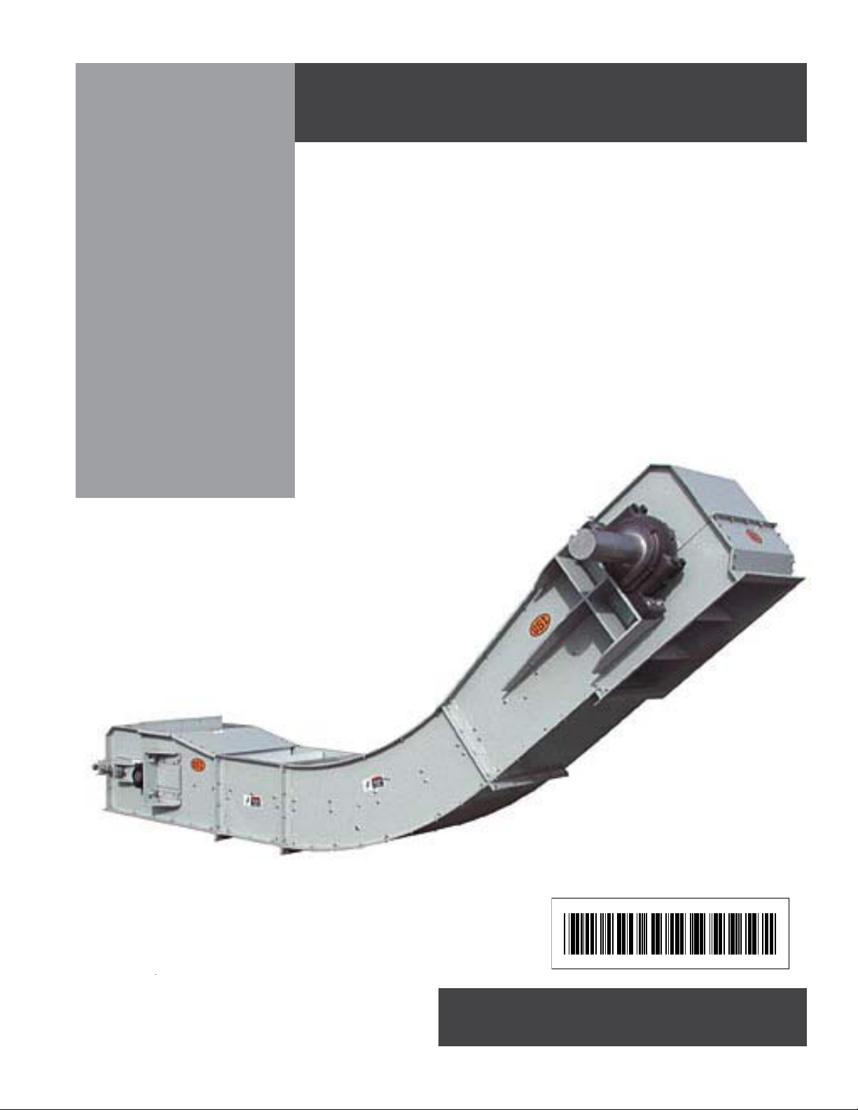
SERIES 2
Incline Chain
Conveyor
Installation and Operation Manual
PNEG-1187
PNEG-1187
Page 2

Introduction
READ THIS MANUAL carefully to learn how to
properly use and install equipment. Failure to do
so could result in personal injury or equipment
damage.
INSPECT THE SHIPMENT immediately upon
arrival. The Customer is responsible for ensuring
that all quantities are correct. Report any damage
or shortages by recording a detailed description
on the Bill of Lading to justify the Customer’s claim
from the Transport Firm. Our responsibility for
damage to the equipment ends with acceptance
by the delivering carrier. Save all paperwork and
documentation furnished with any of the incline
conveyor components.
THIS MANUAL SHOULD BE CONSIDERED a
permanent part of your equipment and should be
easily accessible when needed.
WARRANTY is provided as part of the company’s
support program for customers who use and
maintain their equipment as described in the
manual. The warranty is explained on the warranty page located on the inside back cover of
this manual.
This warranty provides you the assurance that the
company will back its products where defects
appear within the warranty period. In some circumstances, the company also provides field
improvements, often without charge to the customer, even if the product is out of warranty.
Should the equipment be abused, or modified to
change its performance beyond the factory specifications, the warranty will become void and field
improvements may be denied.
i
Page 3

Use of the Equipment Information page will help you identify your equipment in the case that you need to
call your dealer or installer. This information should be filled out and kept on record.
Equipment Information
Model Number:__________________________
Serial Number:___________________________
Material Handling
1004 East Illinois Street
Assumption, Illinois 62510 USA
Phone: (217) 226-4421
FAX: (888) 741-3004
e-mail: gsi@grainsystems.com
Date Purchased:____________________
Dealer/Distributor Name and Phone Number:
ii
Page 4

Table of Contents
Introduction ...................................................................................i
Equipment Information ..................................................................ii
Safety Guidelines ..........................................................................1
Safety ............................................................................................2
Safety Decal Locations. ................................................................6
Installation .....................................................................................11
Care & Maintenance .....................................................................17
Option............................................................................................18
Troubleshooting ............................................................................19
All information, illustrations, photos, and specifications in this manual
are based on the latest information available at the time of publication.
The right is reserved to make changes at any time without notice.
iii
Page 5

NOTES
iv
Page 6

1
Series 2 Incline Chain Conveyors
Safety
SAFETY GUIDELINES
This manual contains information that is important for you, the owner/operator, to know and
understand. This information relates to protecting personal safety and preventing
equipment problems. It is the responsibility of the owner/operator to inform anyone
operating or working in the area of this equipment of these safety guidelines. To help you
recognize this information, we use the symbols that are defined below.
Please read the manual and pay attention to these sections. Failure to read this manual
and it’s safety instructions is a misuse of the equipment and may lead to serious injury or death.
This is the safety alert symbol. It is used to alert you
to potential personal injury hazards. Obey all
safety messages that follow this symbol to avoid
possible injury or death.
DANGER indicates an imminently hazardous situation
which, if not avoided, will result in death or serious injury.
WARNING indicates a potentially hazardous situation
which, if not avoided, could result in death or serious injury.
CAUTION indicates a potentially hazardous situation which,
if not avoided, may result in minor or moderate injury.
CAUTION used without the safety alert symbol indicates a
potentially hazardous situation which, if not avoided, may
result in property damage.
NOTE indicates information about the equipment that you
should pay special attention to.
PNEG-1187
Page 7

2
Safety
GENERAL SAFETY GUIDELINES
1. DO NOT make any alterations to the equipment. Such alterations may produce a very
dangerous situation, where SERIOUS INJURY or DEATH may occur.
2. This equipment shall be installed in accordance with any regulations or installation codes
that are required by law. Authorities having jurisdiction should be consulted before installations are made.
3. Untrained operators subject themselves and others to SERIOUS INJURY or DEATH.
NEVER allow untrained personnel to operate this equipment.
4. Keep children and other unqualified personnel out of the working area at ALL times.
5. NEVER start equipment until ALL persons are clear of the work area.
6. DO NOT operate electric motor equipped units until motors are properly grounded.
Series 2 Incline Chain Conveyors
7. Keep hair, loose clothing, and shoestrings away from rotating and moving parts.
8. NEVER allow any person intoxicated or under the influence of alcohol or drugs to operate
the equipment.
9. Disconnect power on electrical driven units before resetting motor overloads.
10. Make sure someone is nearby who is aware of the proper shutdown sequence in the event
of an accident or emergency.
11. NEVER work alone.
12. ALWAYS think before acting. NEVER act impulsively around the equipment.
13. Do not repetitively stop and start the drive in order to free a plugged condition. Jogging the
drive like this can damage the conveyor and/or drive components.
14. Keep off the equipment at all times.
15. NEVER attempt to assist machinery operation or to remove trash from equipment while in
operation.
PNEG-1187
Page 8
3
Series 2 Incline Chain Conveyors
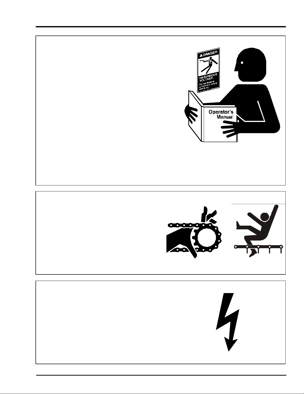
FOLLOW SAFETY INSTRUCTIONS
Carefully read all safety messages in this manual
and on your machine safety signs. Keep signs in
good condition. Replace missing or damaged
safety signs. Be sure new equipment components and repair parts include the current safety
signs. Replacement safety signs are available
from the manufacturer.
Learn how to operate the machine and how to
use controls properly. Do not let anyone operate
without instruction.
Keep your machinery in proper working condition. Unauthorized modifications to the machine
may impair the function and/or safety and affect
machine life.
Safety
If you do not understand any part of this manual
and need assistance, contact your dealer.
STAY CLEAR OF MOVING PARTS
Entanglement in rotating sprockets, chains, and
wiper flights can cause serious injury or death.
Keep all shields and covers in place at all times.
Wear close fitting clothing. Stop and lock out
power source before making adjustments,
cleaning, or maintaining equipment.
OPERATE MOTOR PROPERLY
Do not operate electric motor equipped units
until motors are properly grounded.
Disconnect power on electrical driven units
before resetting motor overloads.
Do not repetitively stop and start the drive in
order to free a plugged condition. Jogging the
drive in this type of condition can damage the
conveyor and/or drive components.
PNEG-1187
Page 9
4
Safety
PRACTICE SAFE MAINTENANCE
Understand service procedures before doing
work. Keep area clean and dry.
Never lubricate, service, or adjust machine while
it is in operation. Keep hands, feet, and clothing
from rotating parts.
Keep all parts in good condition and properly
installed. Fix damage immediately. Replace
worn or broken parts. Remove any build up
grease, oil, or debris.
Series 2 Incline Chain Conveyors
REMOVE PAINT BEFORE WELDING OR
HEATING
Avoid potentially toxic fumes and dust.
Hazardous fumes can be generated when paint
is heated by welding, soldering, or using a torch.
Do all work outside or in a well ventilated area.
Dispose of paint and solvent properly.
Remove paint before welding or heating:
• If you sand or grind paint, avoid breathing the
dust. Wear an approved respirator.
• If you use solvent or paint stripper, remove
stripper with soap and water before welding.
Remove solvent or stripper containers and
other flammable material from area. Allow
fumes to disperse at least 15 minutes before
welding or heating.
PNEG-1187
Page 10

5
Series 2 Incline Chain Conveyors
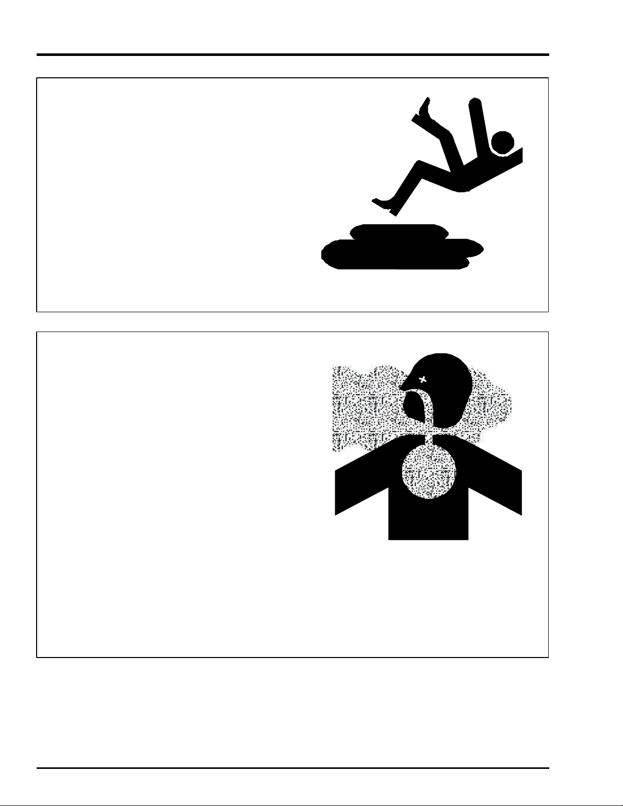
PREPARE FOR EMERGENCIES
Be prepared if fire starts.
Keep a first aid kit and fire extinguisher handy.
Keep emergency numbers for doctors, ambulance service, hospital, and fire department near
your telephone.
WEAR PROTECTIVE CLOTHING
Safety
Wear close fitting clothing and safety equipment
appropriate to the job.
Safety glasses should be worn at all times to
protect eyes from debris.
Wear gloves to protect your hands from sharp
edges on plastic or steel parts.
A respirator may be needed to help prevent
breathing potentially toxic fumes and dust.
Wear hard hat and steel toe boots to help
protect your head and toes from falling debris.
Eye Protection
Gloves
Steel Toe
Boots
Respirator
Hard Hat
PNEG-1187
Page 11
6
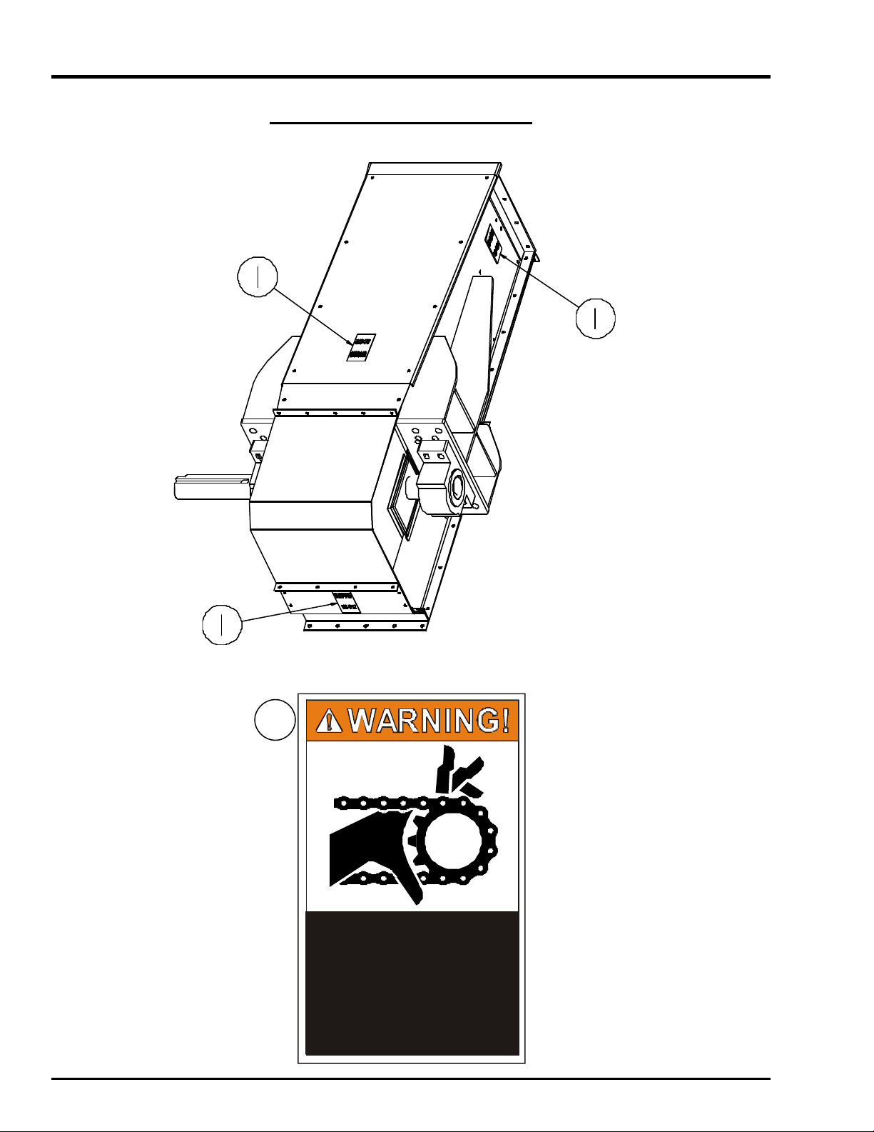
Decals
Moving parts can crush
without guards in place.
result in serious injury.
Series 2 Incline Chain Conveyors
Head Section Decal Locations
1
and cut. Keep hands
clear. Do not operate
Failure to do so could
DC-972
PNEG-1187
Page 12

7
Series 2 Incline Chain Conveyors
Moving parts can crush
without guards in place.
result in serious injury.
Tail Section Decal Locations
Decals
PNEG-1187
1
and cut. Keep hands
clear. Do not operate
Failure to do so could
DC-972
Page 13

8
Decals
2
Series 2 Incline Chain Conveyors
Trough Section Decal Location
2
Exposed conveyors
and moving parts can
cause serious injury.
Lockout power
before removing covers
or inspection door.
DC-1230
o
b
r
e
in
Lo
fo
sp
c
c
r
e
a
a
ko
e
c
E
nd
us
u
re
tio
xp
e
t
m
n
o
m
se
p
o
d
se
o
ri
o
w
v
o
D
C
d
v
i
o
e
in
o
-1
ng
us
r
g
r.
2
c
o
p
i
n
c
3
0
n
a
ju
o
v
v
r
r
e
ey
ts
y
.
rs
o
c
rs
an
2
Exposed conveyors
and moving parts can
cause serious injury.
Lockout power
before removing covers
or inspection door.
DC-1230
PNEG-1187
Page 14

9
Series 2 Incline Chain Conveyors
Bend Section Decal Location
2
Decals
2
2
Exposed conveyors
and moving parts can
cause serious injury.
Lockout power
before removing covers
or inspection door.
DC-1230
PNEG-1187
Page 15

10
Decals
Series 2 Incline Chain Conveyors
Bypass Inlet Decal Location
2
2
2
Exposed conveyors
and moving parts can
cause serious injury.
Lockout power
before removing covers
or inspection door.
DC-1230
PNEG-1187
Page 16

11
Series 2 Incline Chain Conveyors
The head, tail, and intermediate sections of the chain conveyor are shipped
pre-assembled direct from the factory.
Installation
FIG. 1
Head Assembly
FIG. 3
Intermediate Trough Assembly
with Center Pan
FIG. 2
Tail Assembly
FIG. 4
Intermediate Trough Assembly
with Slide Rails
PNEG-1187
Page 17

12
Installation
Series 2 Incline Chain Conveyors
Intermediate Trough Section Assembly
Before assembling conveyor trough sections together
remove covers. It is recommended that you store your
covers in a protected area in order to minimize any possible damage. Remember to retain factory shipped hardware for conveyor cover installation.
Intermediate trough sections are supplied in standard
ten foot (10') lengths. Depending on your application
and individual specifications however, shorter sections
may be required to accommodate a given overall length.
Intermediate sections are supplied with slide rails or a
center pan. The sections with slide rails are generally
used on the horizontal portion of the conveyor. The
sections with the center pans are generally used on the
inclined portion of conveyor.
Note: It is critical for straitness of the conveyor
that the sides and bottom flanges are aligned flush.
Also, it is important that the inside dimensions of
the box measure equidistant from side-to-side both
top and bottom of the trough box (Dimension A =
Dimension B). See Fig. 5.
During assembly of each trough section to the next section, carefully inspect each flange joint to ensure that the
inside bottom and center pan/slide rail side surfaces of
the trough are flush. A chalk line is helpful during this
phase of the assembly to ensure the proper alignment of
the trough surfaces. The maximum run-out in any direction should be +/- 1/4". This proper alignment will minimize wear on flights and other potential damage to the
conveyor. Make sure that the conveyor is level in horizontal applications.
Proceed by attaching the head and tail assemblies using
the same alignment procedures and precautions noted in
the preceding paragraph.
Center Pan
Bottom Plate
FIG. 5
Center Pan Trough Section Shown
PNEG-1187
Page 18

13
Series 2 Incline Chain Conveyors
Installation
Cover Assembly Installation
Before installing the covers, an adhesive back foam
strip may be applied to provide a seal against the
elements. Starting at the tail assembly, place the Tail
Section Cover on top of the Tail Section assembly.
Apply the adhesive back foam strip to the top surface
of the protruding lip before installing the next cover
(See Fig. 7). This recommended installation sequence should ensure that water will shed away from
cover seam connections.
When an inlet is on the conveyor, a cover section
may have to be cut accordingly to accommodate
the inlet. For installation of an inlet, see Inlet
Assembly and Installation.
Inlet Assembly and Installation
One inlet is typically provided per conveyor. Inlets
mounted too close to the tail chain sprocket will allow
grain to come in contact with the sprocket and chain
pinch. This may cause excessive damage to any grain
being conveyed. The minimum distance from tail splice
joint to the nearest edge of the inlet assembly should
be 6".
If the conveyor is control fed and has a center pan,
another opening in the center pan should start at the
edge of the inlet and extend a distance of twice the inlet
opening, towards the tail. The width of the opening
should be determined by starting the opening a distance of 1-1/4" from the inside edge of the conveyor.
(See Fig. 6)
The inlet can be attached with continuous weld seams.
If intermittently welded, it is important to use caulking
or sealing around the inlet area in order to seal the unit.
(Inlet Opening)
Similarly, it is recommended that if inlets are welded
onto the conveyor, this procedure should occur prior
to installation of motor and/or other electrical devices.
By not following this precaution, owner assumes all risks
associated with this type of installation.
Foam Strip
PNEG-1187
FIG. 6
Inlet Assembly
FIG. 7
Foam Strip Placement
Page 19

14
Installation
Series 2 Incline Chain Conveyors
Drag Chain Assembly Installation
All chain now supplied with new conveyors will be installed in a like manner, regardless of type. Correct
total chain length has been determined for your installation by the manufacturer. The conveyor drag chain is
shipped in approximate 10 foot lengths with an additional pre-cut short section, if necessary (refer to packing list). The chain may be installed at any time during
conveyor assembly.
It is recommended however, that you position the
chain over the center pan or slide rail return assemblies and the sprockets in the head and tail assemblies. The UHMW wear pads should be in front of
the welded chain flights in the direction of chain travel
(see diagram below). Connect chain lengths together
with connecting links and/or pins.
Tighten the drag chain assembly using the take-up
screws located on each side of the tail section or on
the take-up head. After the chain is tight, check that
the head and tail shafts are square to the box sides. If
the shafts are not square, loosen the tighter of the two
adjuster screws until the shafts are square. Lock the
adjuster screws by tightening the hex nuts against the
cross-ways “C” channel.
Rotate the chain, now on the sprockets, at least one
complete revolution. Check to see that the chain and
its wear pads are not catching on flanges or rubbing on
the trough sides due to the sprockets not being centered within the box. Ensure a “break-in” period
whereby the chain is allowed to run and seat itself. After running it for an adequate period of time stop the
machine, disconnect and lockout the power source. Retighten as necessary and remove any excess chain portions. Repeat this process as necessary.
FIG. 8
81X Chain Assembly
FIG. 9
4" Pitch Roller Chain Assembly
Direction of Chain Travel
Bottom Run
PNEG-1187
Page 20
15
Series 2 Incline Chain Conveyors
Installing Shaft Mount Reducers
Installation
Assemble torque arm bracket to conveyor per installation instructions found on page 18.
To aid in the installation of the reducer onto the shaft,
remove any protective coating film from shaft. Slide
the reducer onto the drive shaft extending from the side
of the conveyor head section. Using the instructions
and hardware supplied with the reducer, assemble it to
the conveyor drive shaft.
Assemble motor mount to the reducer. Refer to installation instructions provided with motor mount.
Install the rear panel of the drive guard before mounting
the sheaves. The rear panel has four (4) mounting brackets with slotted holes. Attach the lower brackets to the
matching reducer assembly bolts. Attach the upper
brackets to the matching holes in the front motor mount
support.
Assemble the V-belt driven sheave to the input shaft of
the shaft mount reducer. Slide the sheave hub onto the
shaft and insert the square key. Attach the hub sheave
using the supplied retaining screws. The retaining screws
pass through the non-threaded holes of the hub and
into the sheave. Align the driver and driven sheaves
and tighten the retaining screws. During tightening, it is
possible for the sheave to move out of alignment or become out of square. For maximum V-Belt life, the driven
sheave should remain both perpendicular to the drive
shaft and aligned with the drive sheave. Slip the V-belts
over both the driver and driven sheaves.
Adjustment of V-belt tension is achieved by tightening the hex nuts located on the four (4) jackscrews
of the motor base. Adjust motor base equally at all
four bolts to maintain shaft alignment. Belts are
designed to fit loose upon installation. When the
V-belt tension is correct, tighten the top nut on the
jackscrews to lock the motor base in position.
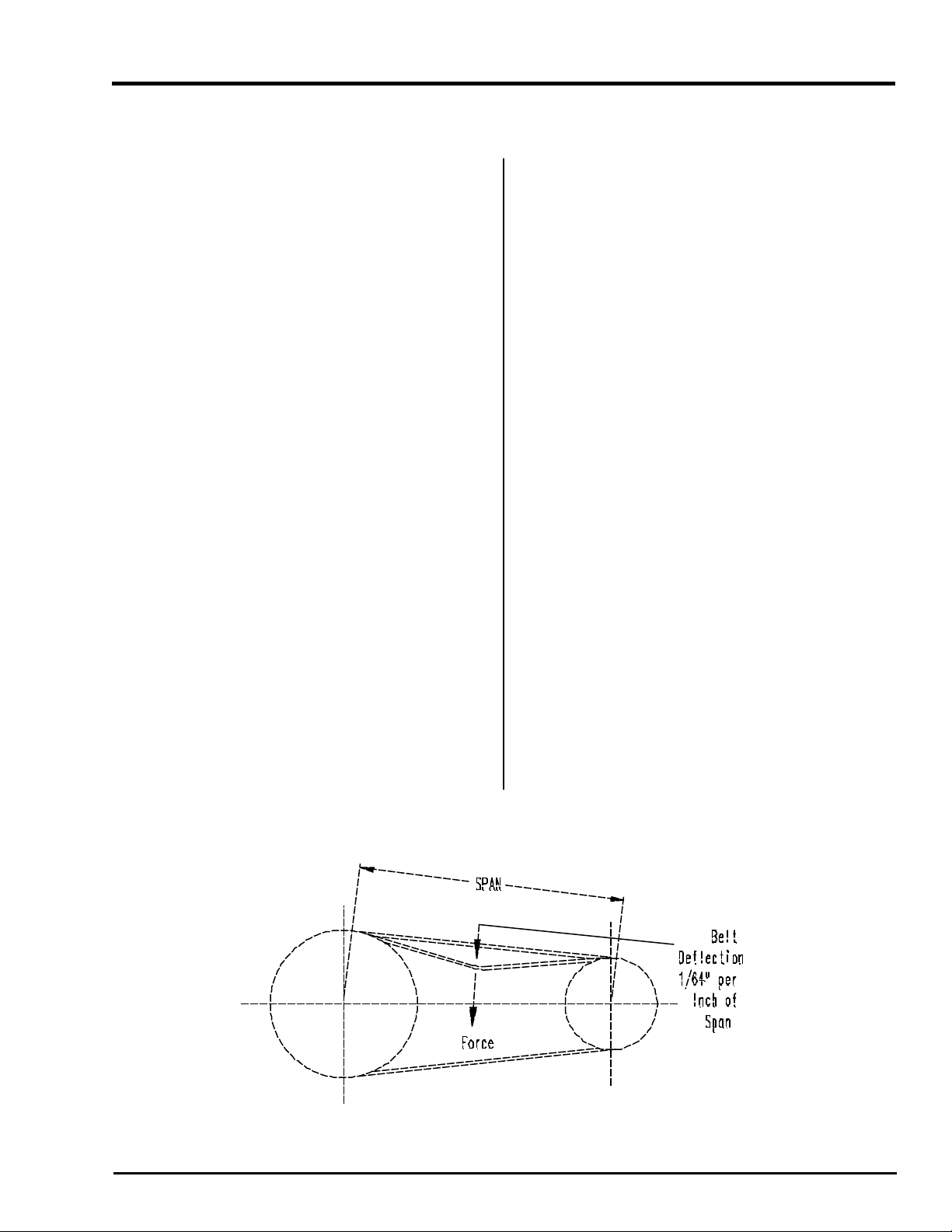
Proper tension is 1/64" of deflection per one (1") inch
of sheave centers on one side of belt, centered between sheaves.
Note: Too much tension shortens belt life. Check
belt tension frequently during the first 24-48 hours
of operation.
Install the front drive guard panel over the four
corner mounting studs. Secure with washers and
nuts provided.
Fill the shaft mount reducer with the manufacturer’s
recommended oil. A list of recommended oil can be
found in the gear reducer instructions.
FIG. 10
Belt Deflection
PNEG-1187
Page 21

16
Installation
Series 2 Incline Chain Conveyors
Welding
Welding on or to the conveyor may cause damage to
both the conveyor and its electrical system. If welding
is necessary, measures should be taken to protect the
conveyor. Should it be necessary to fasten anything to
the conveyor permanently, careful consideration should
be given to methods of maintenance, removal and replacement of the conveyor and/or its parts. (Please
refer to Inlet Installation on pg.13 for the recommended
guidelines).
Motor
Connect the conveyor motor to a power source according to the motor manufacturer’s instructions and
recommendations. To avoid injury it is recommended
that a certified electrician perform the motor wiring. A
shut off switch should be placed near the motor so that
the system may easily be shut down to help prevent
accidents during maintenance. It is important to check
proper motor shaft rotation before installing drive belts
Support
The recommended general guidelines in this area include adequate support for the conveyor assembly to
be installed at intervals no greater than 10 feet. It is
recommended that supports be installed at vertical portions of flanges leaving bottoms of trough sections clear.
By attaching supports in this manner, the removable bottoms are unobstructed for ease of replacement. Support legs are available as an option.
Clearance
A clearance of at least the width of the conveyor is recommended on all sides of the unit. Less clearance may
be acceptable however, serious consideration must be
given to methods of maintenance, removal and replacement of the conveyor and/or its parts.
PNEG-1187
Page 22

17
Series 2 Incline Chain Conveyors
Maintenance
Care and Maintenance
Before any maintenance is performed to
the conveyor, power must be shut off and
locked out to prevent accidental start up!
The care and maintenance section is provided with the
intention of helping to extend the useful life of the unit.
Like all equipment, the useful life of the conveyor is
greatly reduced if not used wisely and well maintained.
Please follow the next few simple steps to ensure
the safety and longevity of your equipment.
w Check all bearings and moving parts daily
during use.
Storage
If the unit is to be inactive for an extended period,
the following procedures are recommended.
w Thoroughly clean the unit.
w Loosen the drag chain tension. Doing so
relieves the stress placed on the bearings
and shafts of the drive and tail sections.
w Lubricate drag chains, shafts and drive
components with a good grade of light
machine oil.
w Lubricate bearings according to bearing
manufacturer’s recommendations.
w Follow manufacturer’s recommendations for
gear reducer lubrication and maintenance.
w Inspect the V-belts periodically for proper
tension and wear. V-belts should be
replaced as necessary. If replacement or
tension adjustment is required, please refer to
the Shaft Mount Reducer Assembly Section
on page 15.
w The Drag Chain and Sprockets should be
checked periodically for wear, damage and
proper adjustment. Any broken or bent
paddles should be replaced or straightened.
Should adjustment or replacement of the
drag chain be required, refer to the
Assembly Section on page 14.
PNEG-1187
Page 23

18
Options
Torque Arm Bracket
Series 2 Incline Chain Conveyors
Installation
When a drive package is ordered with the conveyor
system, a torque arm bracket is provided.
The torque arm bracket is pre-punched for ease of installation to the unit. Begin installation of this option by
first determining the location of the torque arm bracket
relative to the range of extension allowed by the shaft
mount reducer’s torque arm. The bracket will extend
on the same side of the conveyor as the head shaft.
Remove the four bolts necessary from the bottom of
the conveyor plate.
Drill the four holes in the conveyor’s bottom to accommodate the 5/8" hardware provided. Attach the torque
arm bracket to the conveyor using four 5/8” hardware.
Under any circumstances, do not use the 3/8" bolts
previously removed from the conveyor bottom to
attach the torque arm to the conveyor.
Standard Bypass Inlets
The Bypass Inlets come pre-assembled from the
factory. The inlets are available in 3' and 10'
sections. The hogback is stationary in bypass
inlets. Bypass inlets must be mounted horizontally.
If not mounted horizontally, capacity will be reduced.
Install shaft mount reducer to head shaft per instructions on page 14.
Next, match the size of the hardware to the reducer
manufacturer’s torque arm. Use this hardware to attach the torque arm to the bracket. Adequately tighten
all hardware.
When installing torque arm bracket keep angle
(A) of torque arm and reducer between -15°
and +15° of 90° per manufacturer’s recommendations. This angle is shown in Fig. 11.
Torque Arm
Fig. 11
PNEG-1187
Page 24

19
Series 2 Incline Chain Conveyors
Troubleshooting
Trouble Shooting Guide
Problem Cause Solution
Low capacity Improper chain speed Check the shaft RPM
Improper feed Check the grain level at inlet
Plugging Check the discharges
Noisy operation Loose UHMW Paddles Check all bolts on chain and
Bottom and /or Center Pan/ Intermediate Sections
Slide Rails Not Aligned Check Intermediate Trough Section
joints and make flush
Misalignment at Flange Check Intermediate Trough Section
Connections joints and make flush
Worn Drive Components Check oil level and shaft seals
belt misalignment; loose belts
Worn Sprocket Replace
Uneven UHMW Conveyor Misalignment Check the conveyor alignment
paddle wear Sprocket Slipped Check set screws on sprockets
Uneven sprocket wear Worn chain Replace chain (see pg. 14)
Improper alignment Check the sprocket alignment
Consult your contractor for added assistance.
PNEG-1187
Page 25

20
NOTES
Series 2 Chain Conveyors
Page 26

The GSI Group, Inc. Warranty
THE GSI GROUP, INC. (“GSI”) WARRANTS ALL PRODUCTS WHICH IT MANUFACTURES TO
BE FREE OF DEFECTS IN MATERIAL AND WORKMANSHIP UNDER NORMAL USAGE AND
CONDITIONS FOR A PERIOD OF 12 MONTHS AFTER RETAIL SALE TO THE ORIGINAL END
USER. THE PURCHASER’S SOLE REMEDY AND GSI’S ONLY OBLIGATION SHALL BE TO
REPAIR OR REPLACE, AT GSI’S OPTION AND EXPENSE, PRODUCTS THAT, IN GSI’S SOLE
JUDGMENT, CONTAIN A MATERIAL DEFECT DUE TO MATERIALS OR WORKMANSHIP.
ALL DELIVERY AND SHIPMENT CHARGES TO AND FROM GSI’S FACTORY WILL BE
PURCHASER’S RESPONSIBILITY. EXPENSES INCURRED BY OR ON BEHALF OF THE
PURCHASER WITHOUT PRIOR WRITTEN AUTHORIZATION FROM AN AUTHORIZED
EMPLOYEE OF GSI SHALL BE THE SOLE RESPONSIBILITY OF THE PURCHASER.
EXCEPT FOR THE LIMITED WARRANTY EXPRESSED ABOVE, GSI MAKES NO FURTHER
WARRANTY OF ANY KIND, EXPRESS OR IMPLIED, INCLUDING, WITHOUT LIMITATION,
WARRANTIES OF MERCHANTABILITY OR FITNESS FOR A PARTICULAR PURPOSE OR USE
IN CONNECTION WITH (I) PRODUCT MANUFACTURED OR SOLD BY GSI OR (ii) ANY
ADVICE, INSTRUCTION, RECOMMENDATION OR SUGGESTION PROVIDED BY AN AGENT,
REPRESENTATIVE OR EMPLOYEE OF GSI REGARDING OR RELATED TO THE
CONFIGURATION, INSTALLATION, LAYOUT, SUITABILITY FOR A PARTICULAR PURPOSE,
OR DESIGN OF SUCH PRODUCTS.
GSI SHALL NOT BE LIABLE FOR ANY DIRECT, INDIRECT, INCIDENTAL OR
CONSEQUENTIAL DAMAGES, INCLUDING, WITHOUT LIMITATION, LOSS OF ANTICIPATED
PROFITS OR BENEFITS. PURCHASER’S SOLE AND EXCLUSIVE REMEDY IS AS SET FORTH
IN THE LIMITED WARRANTY EXPRESSED ABOVE, WHICH SHALL NOT EXCEED THE
AMOUNT PAID FOR THE PRODUCT PURCHASED. THIS WARRANTY IS NOT
TRANSFERABLE AND APPLIES ONLY TO THE ORIGINAL PURCHASER. GSI SHALL HAVE
NO OBLIGATION OR RESPONSIBILITY FOR ANY REPRESENTATIONS OR WARRANTIES
MADE BY OR ON BEHALF OF ANY DEALER, AGENT OR DISTRIBUTOR OF GSI.
GSI ASSUMES NO RESPONSIBILITY FOR CLAIMS RESULTING FROM ERECTION DEFECTS
OR UNAUTHORIZED MODIFICATIONS TO PRODUCTS WHICH IT MANUFACTURED.
MODIFICATIONS TO PRODUCTS NOT SPECIFICALLY DELINEATED IN THE MANUAL
ACCOMPANYING THE EQUIPMENT AT INITIAL SALE WILL NULLIFY THE PRODUCT
WARRANTY THAT MIGHT HAVE BEEN OTHERWISE AVAILABLE.
THE FOREGOING WARRANTY SHALL NOT EXTEND TO PRODUCTS OR PARTS WHICH
HAVE BEEN DAMAGED BY NEGLIGENT USE, MISUSE, ALTERATION OR ACCIDENT. THIS
WARRANTY EXTENDS SOLELY TO ONLY PRODUCTS MANUFACTURED BY GSI. THIS
WARRANTY IS EXCLUSIVE AND IN LIEU OF ALL OTHER WARRANTIES EXPRESS OR
IMPLIED. GSI RESERVES THE RIGHT TO MAKE DESIGN OR SPECIFICATION CHANGES AT
ANY TIME.
PRIOR TO INSTALLATION, PURCHASER HAS THE RESPONSIBILITY TO COMPLY WITH ALL
FEDERAL, STATE AND LOCAL CODES WHICH MAY APPLY TO THE LOCATION AND
INSTALLATION OF PRODUCTS MANUFACTURED OR SOLD BY GSI.
PHLEGAL: #1832020 v1 (139LG01!.DOC) (revised December 2005)
Page 27

This Equipment shall be installed in accor dance
with the current installation codes and applicable
regulations which should be carefully followed in
all cases. Authorities having jurisdiction should be
consulted before installation occurs.
Rev: 10-16-2006
1004 East Illinois Street
Assumption, IL 62510
217-226-4421 Phone
 Loading...