

Page 1
GSI Network Portable
Dryer Models
Troubleshooting and Reference Manual
PNEG-1181
Date: 09-18-07
PNEG-1181
Page 2

2 PNEG-1181 Portable Dryer Troubleshooting
Page 3

Table of Contents
Contents
Chapter 1 Safety .................................................................................................................................................. 5
Safety Guidelines ............................................................................................................................... 5
Dryer Safety Instructions and Information .......................................................................................... 6
Safety Precautions ........................................................... ... ... .... ... ... ... ... ............................................ 7
Chapter 2 Decals .................................................................................................................................................9
Chapter 3 Operation Tips ................................................................................................................................. 11
Network Dryer Operation Tips .......... .......................................... ... ... ... ... .... ...................................... 11
Chapter 4 Setup Screens ................................................................................................................................. 13
Special Network Dryer Setup Screens ............................................................................................. 13
Chapter 5 Dryer Operation ............................................................................................................................... 14
Network Dryer Options Explanation ................................................................................................. 14
Chapter 6 Programming ................................................................................................................................... 16
Programming Instructions Using Palm Pilot ..................................................................................... 16
Programming Network Dryer Using Palm Pilot ............. ... ... .......................................... ... ... ............. 17
Programming Instructions Using Flash Programmer ....................................................................... 18
Programming Network Dryer Using Flash Programmer ................................................................... 19
Chapter 7 Board Hook Up ................................................................................................................................ 20
Programmer Hook Up Diagram ........................................................................................................ 20
Network Display Board ..................................................................................................................... 21
Input/Output Board ........................................................................................................................... 22
Chapter 8 Troubleshooting Tips ...................................................................................................................... 23
Possible Safety Circuit Shut Down Messages ................................................................................. 23
Input/Output Errors ........................................................................................................................... 27
Master Display Generated Errors ..................................................................................................... 29
PNEG-1181 Portable Dryer Troubleshooting 3
Page 4

Table of Contents
Chapter 9 Wiring Reference ............................................................................................................................. 31
2 Fan Network Dryer Internal Wiring ................................................................................................ 31
2 Fan Network Dryer Internal Jumper Wiring ................................................................................... 32
Upper Control Back Panel Wiring .................................................................................................... 33
Network Upper Control Panel Wiring (220 Volt 3PH) ........................ ... ....... ...... ....... ...... ....... ...... ..... 34
Network Upper Control Panel Wiring (380, 460 and 575 Volt 3PH) ................................................. 35
2 Fan Network Power Circuit Diagram (220 Volt 1PH) (1 of 2) ........................................................ 36
Network Power Circuit Diagram (220 Volt 1PH) (2 of 2) .................................................................. 37
2 Fan Network Power Circuit (220 Volt 3PH) (1 of 2) ...................................................................... 38
Network Power Circuit (220 Volt 3PH) (2 of 2) ................................................................................. 39
2 Fan Network Power Circuit Diagram (440 Volt 3PH) (1 of 2) ........................................................ 40
Network Power Circuit Diagram (440 Volt 3PH) (2 of 2) .................................................................. 41
Network Control Circuit (Main Display Board) (1 of 4) ..................................................................... 42
Network Control Circuit (Input/Output Board) (2 of 4) ................. ..................................................... 43
Network Control Circuit (Meter Roll Sensor-SCR Board) (3 of 4) .................................................... 44
Network Control Circuit (Fan/Heater Board) (4 of 4) ........................................................................ 45
Upper Terminal Strip ........................................................................................................................ 46
Network Upper Terminal Strip (With Moisture Manager Hookup/Relay) .......................................... 47
Moisture Manager Hookup (Network or Competitor) ....................................................................... 48
Input/Output Board Voltage Testing (Located in Upper Control Box) .............................................. 49
Lower Control Box Back Panel Wiring ............................................................................................. 50
Network Fan/Heater Interface (Located in Heater Control Box) .................... ... .... ... ... ..................... 51
Network Fan/Heater Computer Pinouts ........................................................................................... 52
Fan/Can Control Box Wiring (Example: Single Phase Power) ....................... .......... ......... .......... ..... 53
Lower Junction Box Wire Routing .................................................................................................... 54
Upper Junction Box (Wiring) ............................................................................................................ 55
Network Dryer Meter Roll Sensor Rearview (Wiring) ....................................................................... 56
Testing Procedures and Location of Grain Temperature Sensors .................................................. 57
Procedure for Locating, Testing and Replacing a Defective Grain Temperature Sensor ................ 58
Sensor Chart .................................................................................................................................... 60
Procedure for Locating, Testing and Replacing a Defective Plenum Temperature Sensor ............. 61
Procedures for Replacing Network SCR Board .................................................... ... ........................ 63
Chapter 10 Dryer Parts ..................................................................................................................................... 64
Dryer Front Panel (Part Locations) ................................................................................................ 64
Dryer Fan/Can Side View (Part Locations) .................................................................................... 65
Plenum and Grain High Limit Locations ......................................................................................... 66
Chapter 11 Air Switch Tip ................................................................................................................................ 67
Network Series Air Switch Adjustment ........................................................................................... 67
Chapter 12 SCR Board Setup .......................................................................................................................... 69
SCR Board Terminals and Min./Max. Adjustment Locations ......................................................... 69
Setting SCR Board Maximum Voltage ........................................................................................... 70
Setting SCR Board Minimum Voltage ............................................................................................ 71
Chapter 13 Cross Reference ............................................................................................................................ 72
Overload Cross Reference Chart ................................. ... ... .... ... ... .......................................... ........ 72
Motor Cross Reference Chart ........................................................................................................ 74
Chapter 14 Warranty ......................................................................................................................................... 75
4 PNEG-1181 Portable Dryer Troubleshooting
Page 5
1. Safety
Safety Guidelines
This manual contains information that is important for you, the owner/operator, to know and understand.
This information relates to protecting personal safety and preventing equipment problems. It is the
responsibility of the owner/operator to inform anyone operating or working in the area of this equipment
of these safety guidelines. To help you recognize this information, we use the symbols that are defined
below. Please read the manual and pay attention to these sections. Failure to read this manual and its
safety instructions is a misuse of the equipment and may lead to serious injury or death.
This is the safety alert symbol. It is used to alert you to
potential personal injury hazards. Obey all safety
messages that follow this symbol to avoid possible
injury or death.
DANGER indicates an imminently hazardous situation
which, if not avoided, will result in death or serious injury.
WARNING indicates a potentially hazardous situation
which, if not avoided, could result in death or serious injury.
CAUTION indicates a potentially hazardous situation which,
if not avoided, may result in minor or moderate injury.
CAUTION used without the safety alert symbol indicates a
potentially hazardous situation which, if not avoided, may
result in property damage.
NOTE indicates information about the equipment that you
should pay special attention.
WARNING! BE ALERT!
Personnel operating, working or servicing portable dryers should read this manual.
Failure to read this manual and its safety instructions is a misuse of the equipment.
PNEG-1181 Portable Dryer Troubleshooting 5
Page 6
1. Safety
Dryer Safety Instructions and Information
Thank you for choosing a GSI Network Portable Grain Dryer. It is designed to provide excellent
performance and service for many years.
This manual refers to the troubleshooting of the Network Dryer models. Different models are available
for liquid propane or natural gas fuel supply, with either single phase 230 volt, or three phase 230, 460,
575 volt electrical power. (Also 380 volt 50 Hz).
The GSI Group recommends contacting the local power company and having a representative survey
the installation so that wiring is compatible with the system and adequate power is supplied.
Our foremost concern is your safety and the safety of others associated with this equipment. We want
to keep you as a customer. This manual is to help you understand safe operating procedures and some
problems which may be encountered by the operator and other personnel.
As owner and/or operator, it is your responsibility to know what requ irements, hazards and p recautions
exist, and to inform all personnel associated with the equipment or in the area . Safety precautions may
be required from the personnel. Avoid any alterations to the equipment. Such alterations may produce
a very dangerous situation, where SERIOUS INJURY or DEATH may occur.
This equipment shall be installed in accordance with the current installation codes and applicable
regulations which should be carefully followed in all cases. Authorities having jurisdiction should be
consulted before installations are made.
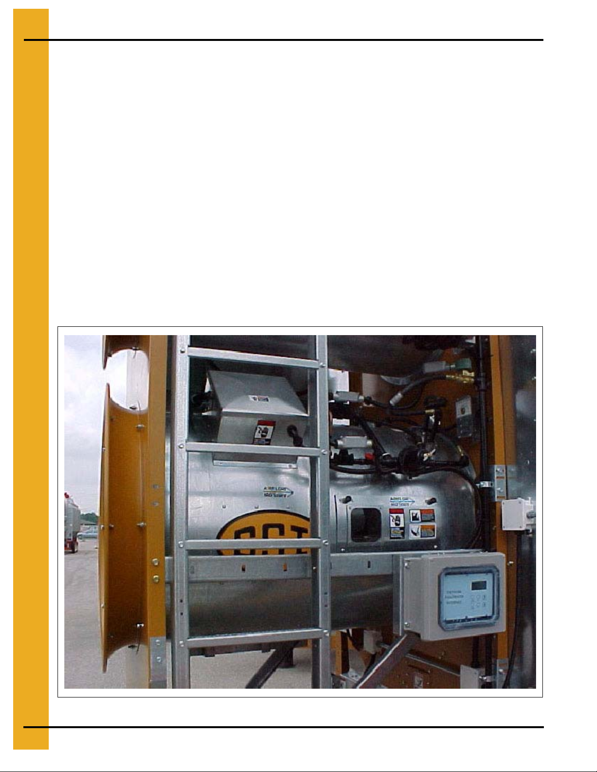
Figure 1A
6 PNEG-1181 Portable Dr yer Troubleshooting
Page 7

1. Safety
Safety Precautions
READ THESE INSTRUCTIONS BEFORE OPERATION AND SERVICE
SAVE FOR FUTURE REFERENCE
1. Read and understand the operating manual before attempting to operate the dryer.
2. Power supply should be OFF for service of electrical components. Use CAUTION in checking
voltage or other procedures requiring the power to be ON.
3. Check for gas leaks at all gas pipe connections. If any leaks are detected, DO NOT operate the
dryer. Shut down and repair before further operation.
4.
NEVER
5. Set pressure regulator to avoid excessive gas pressure applied to the burner during ignition and
when the burner is in operation. DO NOT exceed maximum recommended drying temperature.
6. Keep the dryer clean. DO NOT allow fine material to accumulate in the plenum or drying chamber.
Clean grain is easier to dry. Fine material increases resistance to airflow and requires removal of
extra moisture.
7. Use CAUTION in working around high speed fans, gas burners, augers and auxiliary conveyors
which START AUTOMATICALLY.
attempt to operate the dryer by jumping or otherwise bypassing any safety devices on the unit.
8. DO NOT operate in any area where combustible material will be drawn into the fan.
9. BEFORE attempting to remove or reinstall any propeller, make sure to read the recommended
procedure listed within the servicing chapter of the fan manual.
This product is intended for the use of grain handling only. Any other use is considered a misuse
of the product.
Some edges of the product components can be sharp. Inspect each component to determine
what specific safety considerations to be taken. Any and all necessary personal protective
equipment should be worn at all times when handling, assembling, installing and operating the
product and/or components.
NOTE:
Throughout this manual, guards are removed for illustration purposes only. All guards must be
in place before and during operation.
PNEG-1181 Portable Dryer Troubleshooting 7
Page 8
1. Safety
Use Caution in the Operation of this Equipment
The design and manufacture of this dryer is targeted to maximize operator safety. However, grain
dryers have inherently hazardous components: a gas burner, high voltage electrical equipment, high
speed rotating parts, etc. It is not possible to fully safeguard against all hazards without impeding
efficient operation and reasonable access to components. Therefore, a careful and knowledgeable
owner/operator is the best insurance against an accident.
Use extreme caution when working around high speed fans, gas-fired heaters, augers and auxiliary
conveyors, which may start without warning when the dryer is operating on automatic control.
Keep the dryer clean. Not allow fine material to accumulate in the plenum chamber or surrounding the outside of the dryer.
Continued safe, dependable operation of automatic equipment depends, to a great degree, upon the
owner. For a safe and dependable drying system, follow the recommendations within the Owner’s
Manual, and make it a practice to regularly inspect the operation of the unit for any developing problems
or unsafe conditions.
Take special note of all safety precautions before attempting to operate the dryer.
8 PNEG-1181 Portable Dr yer Troubleshooting
Page 9
2. Decals
ROTATING AUGER
KEEP HANDS, FEET, HAIR AND
CLOTHING AWAY FROM INTAKE.
DO NOT REMOVE OR MODIFY
ANY GUARDS.
KEEP CHILDREN AWAY.
FAILURE TO DO SO WILL
RESULT IN SERIOUS
INJURY OR DEATH.
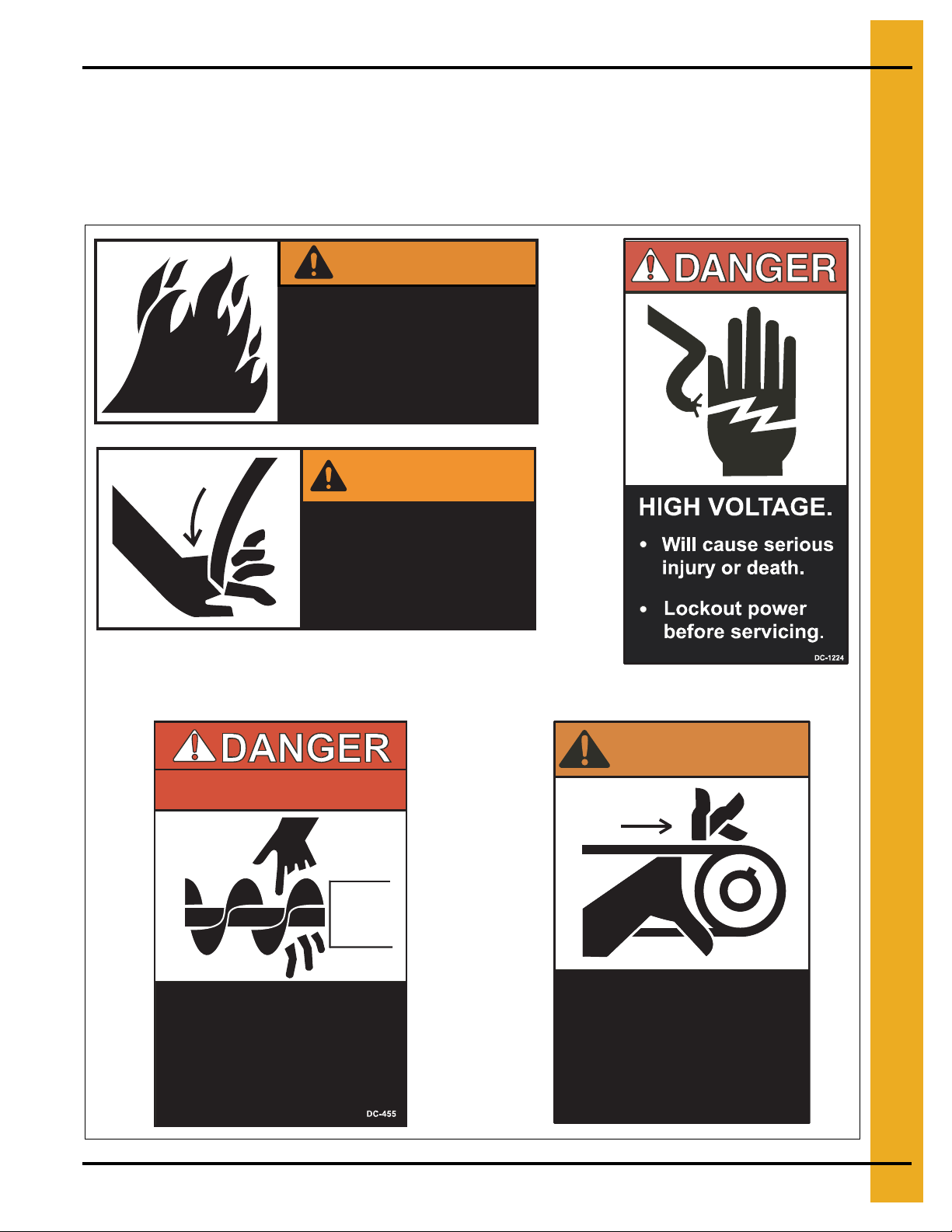
Safety decals should be read and understood by all people in and around the dryer area. If the following safety
decals are not displayed on your dryer, or if they are damaged, contact GSI for replac eme nt.
GSI Decals
1004 E. Illinois St.
Assumption, IL. 62510
Phone: 217-226-4421
WARNING
Flame and pressure beyond
door can cause serious
injury. Do not operate with
service door removed. Keep
head and hands clear.
DC-1227
WARNING
ROTATING AUGER
Stay clear of rotating
blade. Blade could start
automatically. Can cause
serious injury. Disconnect
power before servicing.
DC-1225
WARNING!
FAILURE TO DO SO WILL
PNEG-1181 Portable Dryer Troubleshooting 9
RESULT IN SERIOUS
INJURY OR DEATH.
KEEP HANDS, FEET, HAIR AND
CLOTHING AWAY FROM INTAKE.
DO NOT REMOVE OR MODIFY
ANY GUARDS.
KEEP CHILDREN AWAY.
High speed belt drive
operating overhead.
Can cause serious injury.
Keep head and hands
clear. Do not enter when
dryer is running.
DC-1064
Page 10
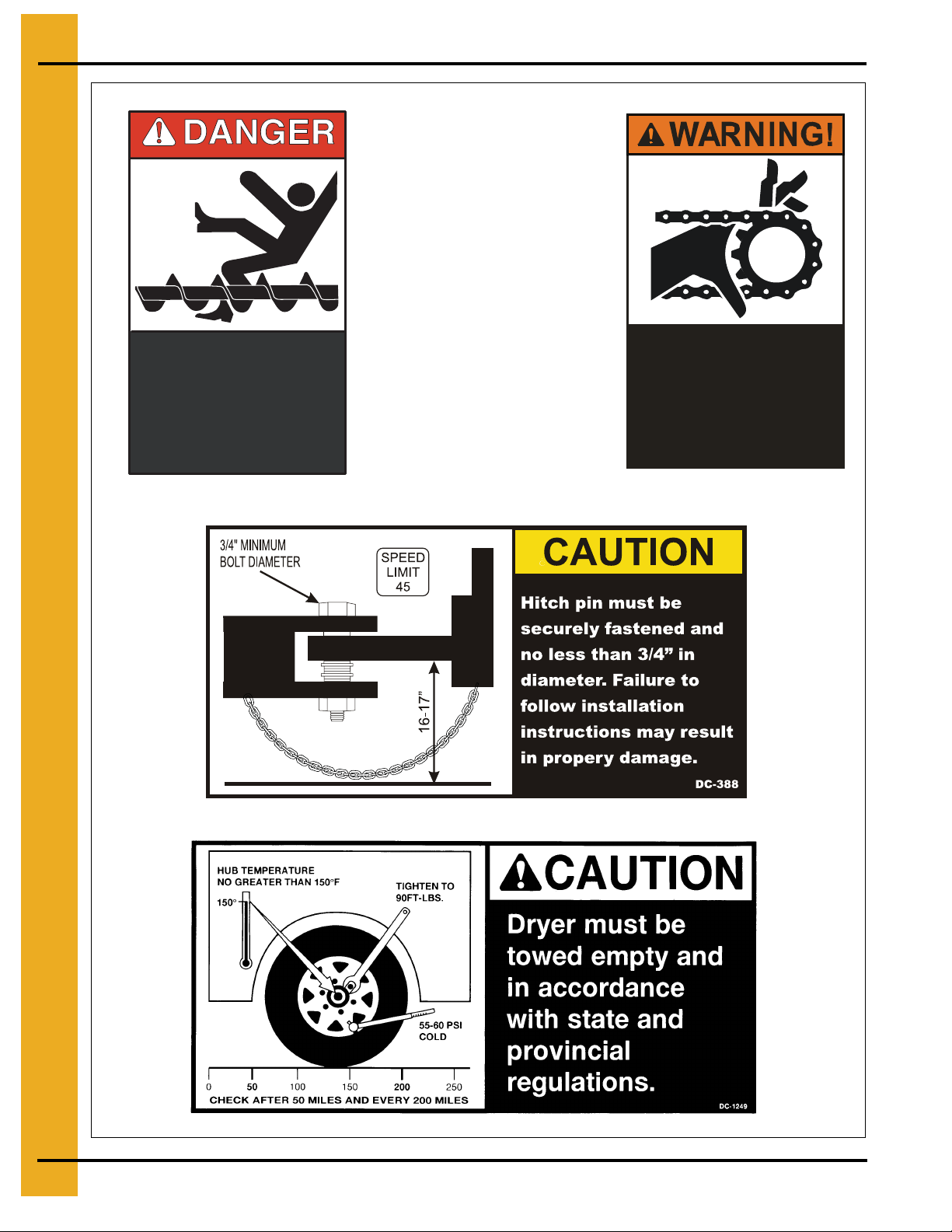
2. Decals
Rotating auger will crush
and cut. Auto equipment
can start at anytime. Do not
enter until electric power is
locked in off position. Failure
to do so will result in serious
injury or death.
DC-974
Moving parts can crush
and cut. Keep hands
clear. Do not operate
without guards in place.
Failure to do so could
result in serious injury.
DC-972
10 PNEG-1181 Portable Dryer Troubleshooting
Page 11

3. Operation Tips
Network Dryer Operation Tips
Important Software and Troubleshooting Tips (Software Version 1.08 and Up).
Present Software Version Numbers: Display 1.19 Heater 1.19 Input/Output 1.18
1. Stuck register value. After installing a new display board and “flashing” the software in, an error
message with “garbage” characters or a negative number for the temperature may appear. To
correct this, hard reboot the system by holding down the reset key and turning the power ON.
Always perform a hard boot after installing a new Display board.
2. If after a hard rebot the screen is still blank, the contrast may need to be adjusted. See tip #6 under
General Tips and Suggestions to adjust the contrast.
3. When flashing new software to the Input/Output board, turn OFF the leveling auger breaker. Due
to design, the leveling auger will run whenever the Input/Output board is being flashed.
4. If only the load and unload augers will not run check to make sure the 110 volt breaker on the Input/
Output board is turned ON.
5. The newest display boards (5/01/02) can now be used on either a Top Dry or Portable Dryer.
In the past a dryer display board had to have wires soldered in place for the meter roll speed
potentiometer. The newest boards have a six pin connector that connects to the meter roll
speed potentiometer.
6. The metering roll speed potentiometer connection at the potentiometer is correct when the visible
copper on the connector is in the bottom.
7. As dryers age, the contacts in the safeties start reducing the amount of DC voltage passed through
and may need to be replaced. Check the voltage if repeated error warnings are received from what
appears to be a good safety.
General Tips and Suggestions
1. In software version 1.19, the moisture control differential was reduced from 4° to 2°. As a result, the
dryer will cycle quicker and control moisture better.
2. In software version 1.18, the ability to calibrate bushels readings was added.
3. In software version 1.17 and greater, holding down the UP and DOWN arrow keys while changing
the timer or delay setting will start changing the setting at a much faster rate.
4. In version 1.17 and greater, pressing reset while changing a timer or delay setting will return the
setting to its default setting.
5. To enter the switch and keypad test function for diagnostic purposes, press and hold the HELP
button in. Turn ON the control power and release the HELP button. Turn any of the switches or
press any of the keypad buttons, and the one that you activated will be displayed on the screen.
6. To enter the screen adjustment mode, press the SCREENS button while turning the control power
on. Use the UP and DOWN arrow keys to adjust the current level of contrast. NOTE: Continued
depression of the arrow keys (UP or DOWN) will not adjust the contrast. Instead, each press and
release of the arrow keys (UP or DOWN) will adjust the contrast slightly. Because of this, adjusting
the contrast from a dark or blank screen to a visible screen will require many (100 or more) repeated
presses of the arrow keys.
PNEG-1181 Portable Dryer Troubleshooting 11
Page 12

3. Operation Tips
Network Dryer Operation Tips (Continued)
7. To return all options and settings to the factory defaults, press and hold the RESET button. Turn
the control power ON and release the RESET button. NOTE: ALL settings will be erased and all
options will return to the factory defaults.
8. To disable the air pressure switches, press and hold both the GRAIN and PLENUM buttons. Turn
ON the control power and release the buttons.
9. To erase all shut downs in the computer history, press and hold both the DRY and COOL buttons
and turn ON the control power. Release the buttons.
10. To view the shut down history of the dryer, press the UP and DOWN arrow buttons at the same
time, prior to pressing the START switch on the dryer. 256 dryer shut downs are stored in memory.
Performing this keystroke sequence while changing a timer or a delay setting, will change the
setting to 0.01.
11. Press the SCREENS button while the dryer is running to access the following data:
A. Out of Grain - View “Out of Grain” Timer
Set “Out of Grain” Timer
Check “Last Load” Time
B. View Grain Temps
C. User Hour Meter (Hour meter can be reset here also).
D. Meter Roll Speed Average. (Monitors the percentage of time the meter rolls spend on both high
and low speed.)
12. Press the
A. Enter the BPH factor (software version 1.18)
B. Reset batch counter
C. Clear total bushels
D. Change user message
13. Press DELAYS button before pressing start on the dryer in order to access the following Delays:
A. Load Delay
B. Out of Grain
C. Fan Delay
D. Unload Clean Out Delay
SETUP
button, before pressing start on the dryer in order to change the following settin gs:
12 PNEG-1181 Portable Dryer Troubleshooting
Page 13
4. Setup Screens
Special Network Dryer Setup Screens
There are certain dryer features that rarely need to be changed a nd which should be carefully considered
before adjusting. To access these advanced features, with the power OFF, press and hold the
button and then turn ON the control power for the dryer. Release the
MODIFY
button and the advanced
feature screens will be available.
Pressing ENTER after releasing the Modify button will allow you to view and/or change the special setup
screens in the following sequential order:
Option Select
1. Turn Meter Rolls OFF No——Yes
2. Air Switch Testing Yes——No
3. Meter Roll Reverse No——Yes
A. Reverse Time 5 Minutes, but is adjustable
B. Forward Time 55 Minutes, but is adjustable
4. Select Unload Method 2 Speed——3 Speed
5. Select Dryer Address 01——for use with the Watchdog program only
6. Attempt to Refill No——Yes
7. Enter Model Number Dryer Model Number NOTE: Dryer Model Number mu st
be exact in order for the dryer to operate properly.
8. Temperature Scale Fahrenheit——Celsius
9. Change Burner Setup Enter to Change——Reset to Bypass
A. High/Low Fire or ON/OFF Fire High/Low Fire——ON/OFF Fire
B. Active or Inactive Active——Inactive
10. Set Time and Date Time and Date
1 1. Load System End Fill——Center Fill——Dual Fill
12. Unit of Measure Bushels——Metric Tons
13. Change Burner Differential Enter to Change——Reset to Bypass
A. Set Burner Differential in Degrees Default is 3 Deg rees in High/Low and 1° in ON/OFF Fire
This default is not effecti ve unt i l software version 1.16
MODIFY
Selections in bold are the default settings
Series 2000 Fan and Heater Dip Switch Settings:
NOTE: These are set at the factory but will need to be reset when changing out a board.
Fan 1 #1 OFF / All Others ON
Fan 2 #2 OFF / All Others ON
Fan 3 #1 and #2 OFF / All Others ON
Fan 4 #3 OFF / All Others ON
Fan 5 #1 and #3 OFF / All Others ON
Fan 6 #2 and #3 OFF / All Others ON
PNEG-1181 Portable Dryer Troubleshooting 13
Page 14

5. Dryer Operation
Network Dryer Options Explanation
Turn Meter Rolls OFF
This option does not actually turn off the metering rolls. Changing this setting to YES removes the
sensor board from the circuit and allows the dryer to operate normally, but without any meter roll
information displayed on the screen. This is useful in the event of a sensor board failure. The sensors
on the rear of the dryer and the computer monitor whether or not the metering rolls are turning when the
UNLOAD is running. They also calculate the RPM, total bushels and Bushels Per Hour (BPH) of the
grain flowing across the meter rolls. If the meter rolls do not show movement in a two-minu te period, the
computer will shut down the dryer with a Meter Roll Drive System Failure. If, upon restarting the dryer
the meter rolls work properly, the drive system itself is okay and the problem is the sensor board itself.
Run the dryer normally by switching this setting to YES. Replace the board as soon as possible and
return this setting to ON when possible.
Air Switch Testing
Setting this option to NO allows the dryer to run without proving airflow. When a fan starts, it has
20 seconds to develop air pressure in the plenum of the dryer. If pressure develops, the dryer operates
normally. If no pressure develops, the dryer will shut down with a Loss of Airflow Shut Down error
message. Changing this setting to NO allows the user to run the fan on the dryer if a switch becomes
defective. It also allows the user to run the fan on the dryer without grain inside of it. This option resets
every time there is a dryer power loss of the dryer control power is shut OFF. Therefore, when restarted,
the setting will default back to YES and require proof of airflow again. Change this option to NO to run the
fan on the dryer without grain or with a defective switch until it is replaced.
Meter Roll Reverse
When set to YES, the meter rolls will run in the normal direction but, will occasionally slow to a stop and
then run in the reverse direction for a short period of time. The amount of time the meter rolls run in
forward and in reverse is adjustable and programmable. This option will not be used regularly but is
useful when grain conditions are very poor.
Select Unload Method
The Select Unload Method is set to a default of 2 Speed. In this setting, meter rolls will speed up and
slow down as needed to maintain constant grain moisture at the discharge of the dryer. While a
3 Speed option is under development, it is not available on this software and this setting should, remain
on 2 Speed.
Select Dryer Address
Most owners will not use this setting as it requires the use of the GSI Watchdog software program to
operate. This option allows the user to assign an address for each dryer on the network to be monitored
by the Watchdog program. The system can monitor up to 10 dryers and log dryer functions whenever
any of the dryers are running.
Attempt to Refill
Setting this option to YES enables the dryer to monitor the Out of Grain Timer. When the dryer runs low
and the Out of Grain Timer runs down, the dryer will go into a “hold” mode instead of shutting down. In
the “hold” mode, the unload auger shuts down, the burner turns off and the fan and the load auger
continue to run. If the dryer fills back up with grain, the burner will turn on again and the unload auger
will start up as well.
14 PNEG-1181 Portable Dryer Troubleshooting
Page 15

5. Dryer Operation
Dyer Model Number
This setting is critical to proper function of the dryer. The actual model number of the dryer is located
here and that number contains a great deal of valuable information about the dryer, including: number
of fans, number of modules, and the length of the dryer. This data is used by the computer to operate
the dryer properly. If any of this information is incorrect, the dryer will not operate properly and may not
operate at all. Use tremendous caution when changing this setting.
Temperature Scale
This option allows the user to toggle the temperature scale between Fahrenheit to Celsius.
Change Burner Set-Up
This setting controls the operation of each fan/heater unit on the dryer. Users can run any burner, or any
combination of burners, on either High/Low Fire or On/OFF Fire. This setting also allows users to render
a problem fan/heater inactive, thereby removing it from the programming of the dryer and allowing the
remainder of the dryer to continue running until the problem fan/heater can be repaired or replaced.
Set Time and Date
Use this setting to enter, store and adjust the time and date information.
Select Load System
While most dryers use the end fill option, GSI dryers also have the ability to run center fill and dual fill
modes if needed.
Unit of Measure
This setting allows the dryer to perform calculations in metric tons instead of bushels. This option is
useful for applications in foreign countries.
Change Burner Differential
The burner differential is the number of degrees that a fan/heaters temperature must drop before it will
cycle. Proper burner cycling means three (3) to four (4) times a minute the fan/heater should cycle from
high to low pressure. For this to happen, the burner must first reach the set point. The set point is the
desired running temperature for the plenum, usually around 220 degrees. When this temperature is
reached, the burner will shut off one solenoid and divert all of the gas through the low pressure ball
valve and the low pressure solenoid. Turn down the low pressure ball valve far enough to allow the
temperature to start to fall. When the temperature falls the number of degrees set by the differential, the
burner will cycle back to high. Keep in mind the burner should cycle three (3) to four (4) times a minute.
PNEG-1181 Portable Dryer Troubleshooting 15
Page 16
6. Programming
Programming Instructions Using Palm Pilot
There are three (3) boards to program on the Network Dryer: Display Board (lower control box),
Input/Output Board (upper control box), and Heater Interface Board (by Fan/Can housing).
1. Turn the control power on the dryer to the OFF position.
2. Locate the programming jack on each individual board:
• Display Board (lower control panel) - (DB-9) located at bottom of board.
• Input/Output Board (upper panel) - (DB-9) located at bottom of board.
• Heater Interface Board (by fan/can housing) - (J2 connector) located on back of board.
NOTE: Refer to See Figure 6A on Page 17.
3. If programming the Input/Output Board or Display Board, connect the DB-9 connector from the
Palm Pilot to the board.
4. If programming the Heater Interface Board, connect the J2 connector on the series 2000 cable to
the J2 connector on the back of the board.
5. Unplug the network connection (yellow and blue wires) to the board being programmed.
6. On the Palm Pilot, select the program for that particular board and select it by “tapping” on it.
7. Turn the dryer control power back ON.
8. The programming process begins by erasing the present program and starting the new program.
9. The screen will display a confirmation screen when the transfer of the software is complete.
10. Turn the dryer control power OFF and remove the connector from the board. Plug the network wires
back into the board being programmed.
11. Turn ON the dryer and the opening screens on the dryer will indicat e the latest version of software.
There are two Palm Pilot kits available from GSI for order:
Ref # Part # Description
D03-0692 (Palm Flash Program Kit Deluxe)
1 D01-1771 Series 2000 Programming Cable
2 D03-0688 Palm Pilot IIIC (color)
3 D03-0694 Palm Pilot Hot Sync Cable
4 D03-0695 Palm Flash 9 Pin M-M Adapter
5 D03-0709 Disk, CD-ROM Palm Flash Software
D03-0693 (Palm Flash Program Kit Economy)
6 D01-1771 Series 2000 Programming Cable
7 D03-0689 Palm Pilot M100 (black & white)
8 D03-0695 Palm Flash 9 Pin M-M Adapter
9 D03-0709 Disk, CD-ROM Palm Flash Software
16 PNEG-1181 Portable Dryer Troubleshooting
Page 17
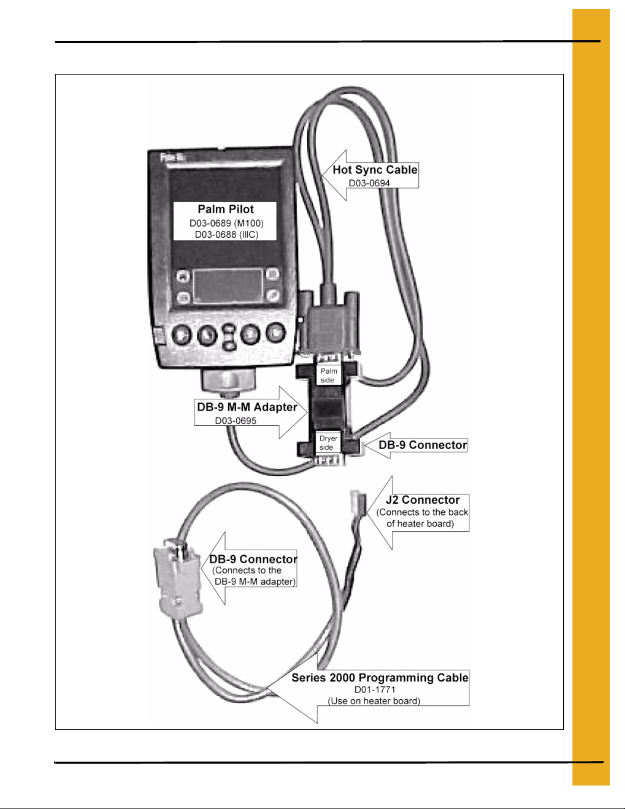
Programming Network Dryer Using Palm Pilot
6. Programming
Figure 6A
PNEG-1181 Portable Dryer Troubleshooting 17
Page 18

6. Programming
Programming Instructions Using Flash Programmer
There are three (3) boards on the Network Dryer to program: Display Board (lower control box),
Input/Output Board (upper control box), and the Heater Interface Board (Fan/Can housing).
1. Turn the control power on the dryer to the OFF position.
2. Locate the programming jack on each individual board:
• Display Board (lower control panel) - (DB-9) located at bottom of board.
• Input/Output Board (upper panel) - (DB-9) located at bottom of board.
• Heater Interface Board (by fan/can housing) - (J2 connector) located on back of board.
NOTE: Refer to See Figure 6B on Page 19.
3. If programming the Input/Output Board or Display Board, connect the DB-9 connector from the
Flash Programmer to the board.
4. If programming the Heater Interface Board, connect the J2 connector on the series 2000 cable to
the J2 connector on the back of the board.
5. Unplug the network connection (yellow and blue wires) to the board being programmed.
6. Make sure the rotary switch on the programmer is set to position 8.
7. Turn the dryer control power back ON.
8. The four lights on the programmer will come ON, then three will go out leaving only the power light
still illuminated.
9. Push the Start button on the programmer to start the transfer of software.
10. The Busy light will flash until the transfer process is complete.
11. When completed, the Pass light will illuminate, indicating a successful transfer.
12. After a successful transfer, turn control power OFF, remove connector from the board and plug the
network wires back into the board being programming.
13. If the Fail light flashes, check the connection and repeat the above process.
14. Turn ON the dryer and the opening screens of the dryer should indicate the latest version of software.
18 PNEG-1181 Portable Dryer Troubleshooting
Page 19
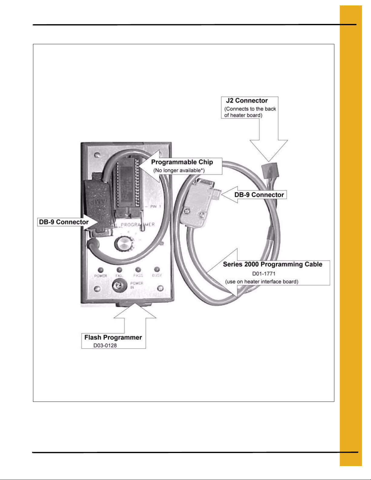
Programming Network Dryer Using Flash Programmer
6. Programming
Figure 6B
*The Flash Programmer can still be used to program the dryer but the programmable chip for it is no
longer available. Therefore, GSI recommends using a Palm Pilot for programming.
PNEG-1181 Portable Dryer Troubleshooting 19
Page 20
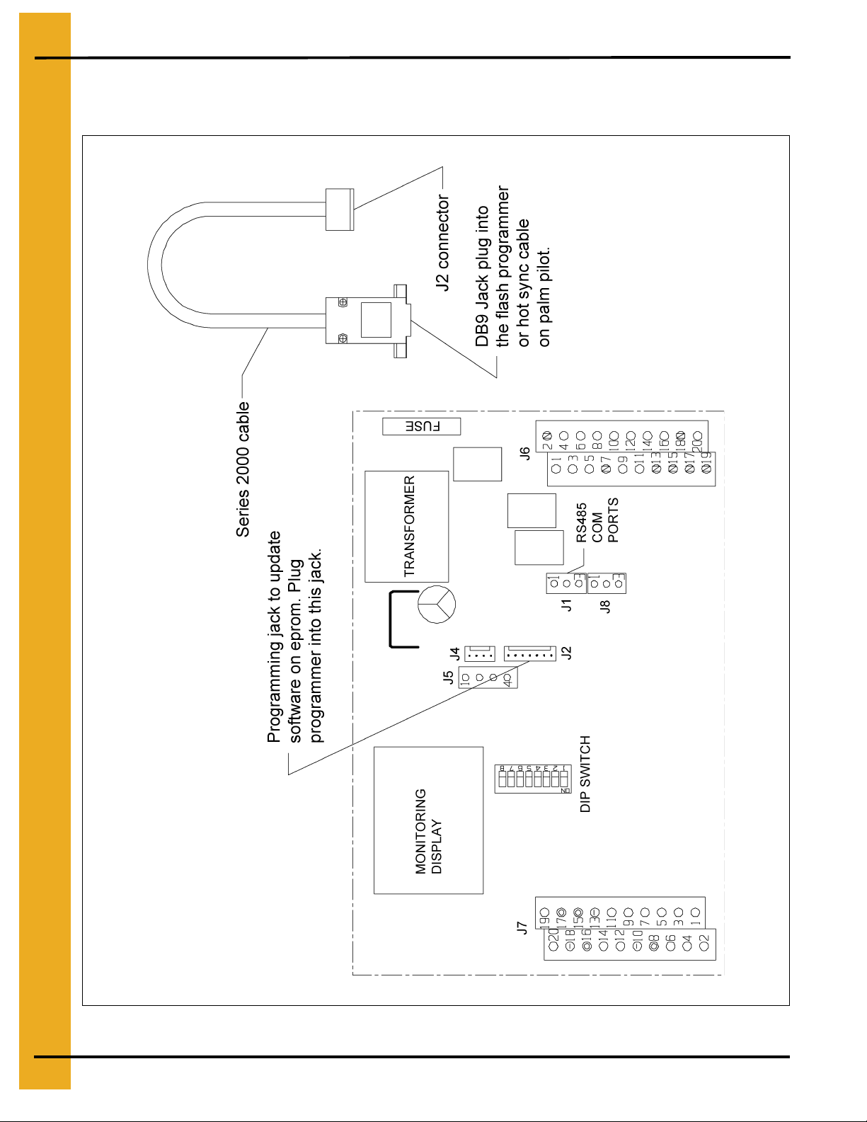
7. Board Hook Up
Programmer Hook Up Diagram
(Located in Heater Control Box) (Back of Heater Board)
Figure 7A
20 PNEG-1181 Portable Dryer Troubleshooting
Page 21
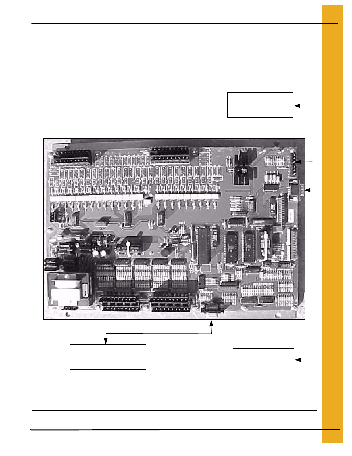
Network Display Board
(Located in the lower control panel) (Back of Board)
7. Board Hook Up
Network
Terminal connections
(blue and yellow wires)
DB-9 Connector
This is used for
programming the board.
Figure 7B
PNEG-1181 Portable Dryer Troubleshooting 21
DB-9 Connector
This is used for
Watchdog Program
.
Page 22
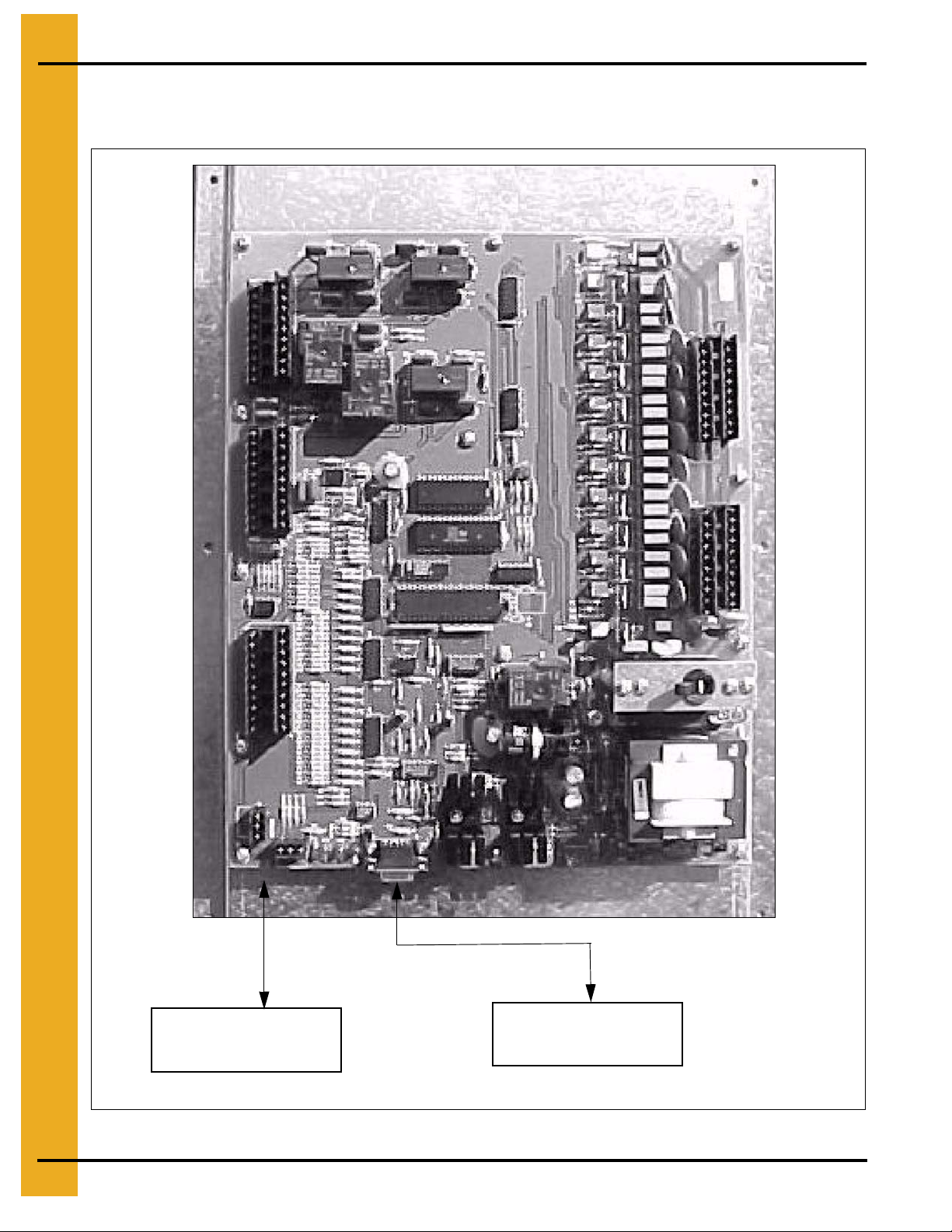
7. Board Hook Up
Input/Output Board
(Located in Upper Control Panel)
Network
Terminal connections
(blue and yellow wires)
Figure 7C
22 PNEG-1181 Portable Dryer Troubleshooting
DB-9 Connector
This is used for
programming the board.
Page 23

8. Troubleshooting Tips
Possible Safety Circuit Shut Down Messages
Viewing the Shut Down History
The shut down history can store up to 200 shut down warnings. When the dryer exceeds this amount,
the oldest shut down will be erased and replaced with the current shut down warning.
To view the shut down history (Warnings):
• Turn the Control Power to ON.
• Wait until the time and date screen appears and then press the START button.
• Press the increase and decrease buttons at the same time while the dryer is stopped. Then,
scroll through the history by pressing either the increase or decrease buttons. Press enter
to exit this screen or press stop to clear the shut down warning.
Shut Down Message Listing
The following is a list of all possible shut down messages for the network dryer. They are broken down
with their associated controller where the error originated. The message on the screen will show
WARNING at the top followed by the error, time, date and in which fan/heater the error occurred.
FAN X LOSS OF AIRFLOW
Fan 1 Loss of Airflow: The contacts in the air switch have opened due to insufficient air pressure in
the plenum. The message will identify which plenum caused the shut down.
Hints
Verify that the fan is running and that the dryer is completely full of grain. If the air pressure switch is
sensing air pressure, the blue light in the fan switch will come on after the fan has reached half speed. If
it does not, adjust the air switch using a straight blade screw driver to turn the adjusting screw on the air
switch counter-clockwise.This will make it more sensitive to air pressure. If this does not solve the problem,
inspect the wiring circuit of the air pressure switch. Each air pressure switch is wired to the Network
fan/heater Interface located on each individual fan/can box. Use a voltmeter on the following terminals:
Black Probe (J7-10) DC Negative
Red Probe (J7-09) 0 VDC Fan Running Red Probe (J7-09) 5 VDC Fan Stopped
Red Probe (J7-11) 5 VDC Fan Running Red Probe (J7-11) 0 VDC Fan Stopped
If operating correctly, the voltmeter should display the reading listed above.
Any other reading may indicate a bad switch, computer board, air pressure
switch or wiring.
If all this fails to work, remove the wires from the air pressure switch and remove the switch from the
dryer. Blow into the air tube to simulate air pressure in the plenum. The switch should have an open
circuit. Blow into the switch to close it. If it fails to close try adjusting it or replacing it.
Remember
1. Dryer must be full of grain. (Make sure fill is keeping up with unload.)
2. Check to see if light comes ON when fan is running.
3. Make sure the bulb is good. It is a 110 VAC.
PNEG-1181 Portable Dryer Troubleshooting 23
Page 24

8. T roubleshooting Tips
Possible Safety Circuit Shut Down Messages (Continued)
4. Make adjustments on air pressure switch one quarter turn at a time.
5. Clean air pressure switch tube to make sure it is not plugged.
6. More on how to adjust air switch on Page 57.
AIR SWITCH X STUCK
Air Switch 1 Stuck: Air pressure switch contacts have closed prior to the fan starting, indicating a
freewheeling blade or improper adjustment of the air switch. The error message will show on which fan
the error occurred.
HOUSING X HIGH LIMIT
Housing 1 High Limit: This occurs when there is an overheat in the fan housing of 200°F and a
thermo disc has opened. It is located directly on top of the individual fan housing and must be manually
reset. The high limit is wired directly to the fan/heater interface mounted to that particular fan. If it does
not clear after resetting and pushing the stop button, check the fan/heater interface. The error message
shows on which fan/heater the error occurred.
Use a voltmeter on the following terminals:
Black probe (J7-10) DC negative
Red probe (J7-16) 12 VDC output
Red probe (J7-02) 12 VDC when closed
GRAIN X OVERHEAT
Grain 1 Overheat: This occurs when the grain temperature in one of the columns has reached
210°F. The fixed temperature thermo disc has opened. This will automatically reset when it cools down.
Check each grain column and make sure the grain is moving down the column screen. If it does not clear
after pushing the stop button, check the fan/heater interface.
Use a voltmeter on the following terminals:
Black probe (J7-10) DC negative
Red probe (J7-08) 12 VDC output
Red probe (J7-05) 12 VDC when closed
PLENUM X OVERHEAT
Plenum 1 Overheat:
300°F. The fixed temperature thermo disc has opened. This will automatically reset when it co ols down. If
it does not clear after pushing the stop button, check the fa n/heater interface.
Use a voltmeter on the following terminals:
Black probe (J7-10) DC negative
Red probe (J7-15) 12 VDC output
Red probe (J7-03) 12 VDC when closed
This occurs when the plenum temperature inside the p lenum has reached
24 PNEG-1181 Portable Dryer Troubleshooting
Page 25

8. Troubleshooting Tips
Possible Safety Circuit Shut Down Messages (Continued)
VAPOR X HIGH LIMIT
Vapor 1 High Limit:
the vaporizer, has opened indicating that the vaporizer is ru nnin g too hot and must be adju ste d. This senso r
is set at 200°F and will automatically reset itself when cool. Adjust the vaporizer coil away from the burner
flame. Make sure the LP tank has fuel in it. Also, try switching to ON/OFF cycle rather than High/Low,
especially on warmer days. If the error still does not clear after pushing the stop button, check the fan/heater
interface. The error message shows on which heater this condition occurred.
Use a voltmeter on the following terminals:
Black probe (J7-10) DC negative
Red probe (J7-16) 12 VDC output
Red probe (J7-01) 12 VDC when closed
The LP gas vapor temperature sensor, located in the ga s pipe train downstream from
GRAIN TEMP OPEN X
Grain Temp Open 1: This error indicates there is a open condition with one of the grain temperature
sensors located inside the left or right grain columns. This could be a open sensor or the sensor wires
could be disconnected. These sensors are wired to a fan/heater interface, which one depends on the
model of dryer. Refer to the Dryer Front Panel Parts Location Wiring for location of the actual sensors.
The terminals they are wired to are as follows:
Grain Temp Sensor Ground - (J7-18)
Grain Temp Sensor - (J7-14)
When testing these sensors to see if they are bad refer Temperature Chart (Series 2000 Temp Sensors)
on Page 60 and also Grain Sensor Testing on Page 57.
GRAIN TEMP SHORT X
Grain Temp Short 1: This error indicates a shorted condition with one of the grain temperature
sensors located inside the left or right grain columns. This could be a shorted sensor or the sensor wires
could be shorted together. The sensors are wired to a fan/heater interface. Refer to the Dryer Front
Panel Parts Location Wiring more complete information.
The terminals they are wired to are as follows:
Grain Temp Sensor Ground - (J7-18)
Grain Temp Sensor - (J7-14)
When testing these sensors to see if they are bad, refer to the Temperature Chart (Series 2000 Temp
Sensors) on Page 60 and also Grain Sensor Testing on Page 57.
PLENUM TEMP OPEN X
Plenum Temp Open 1: This error indicates an open condition with the plenum temperature sensor
located inside the plenum chamber. This could be an open sensor or the sensor wires could be
disconnected. These sensors are wired to a fan/heater interface, which one depends on number of
plenums. The error message will show in which plenum the opening occurred. Refer to the Dryer Front
Panel Parts Location Wiring for location of the actual sensors. The terminals they are wired to are as
follows:
Plenum Temp Sensor Ground - (J7-13)
Plenum Temp Sensor - (J7-12)
PNEG-1181 Portable Dryer Troubleshooting 25
Page 26

8. T roubleshooting Tips
Possible Safety Circuit Shut Down Messages (Continued)
PLENUM TEMP SHORT X
Plenum Temp Short 1: This error indicates a shorted condition with the plenum temperature sensor
located inside the plenum chamber. This could be a short in the sensor or the sensor wires. These
sensors are wired to a fan/heater interface, which sensor contains the short depends on number of
plenums. The error message will show in which plenum the short occurred. Refer Dryer Front Panel
Parts Location Wiring for location of the actual sensors.
The terminals they are wired to are as follows:
Plenum Temp Sensor Ground - (J7-13)
Plenum Temp Sensor - (J7-12)
FLAME LOSS X
Flame Loss 1:
been established. This may be caused by the flame probe no t being directly in the flame path, loss of fuel, or
a problem with the burner circuit. Sometimes, the loss of flam e occurs when the burner cycles to Low Fire. To
correct this error, adjust the gas pressure or adjust the flame probe to where it is in the flame path at all times.
Remove the access door on the side of the fan/heater housing to allow access to the flame probe.
Another way to see if the burner is sensing flame correctly is to watch the light in the burner switch. If it
starts to flicker, an adjustment may need to be made on the flame probe. The flame probe wire and
ground wire are connected to the fan/heater interface. The error messag e will show in which heater the
flame loss has occurred.
The terminals they are wired to are as follows:
Flame Probe Ground - (J7-20)
Flame Probe Wire - (J7-19)
This error indicates that the flame probe has failed to detect a burner flame that had already
Make sure power is OFF while adjusting the gas pressure or flame probe to
correct the Flame Loss error.
IGNITION FAILURE X
Ignition Failure 1: This happens when the burner fails to light. Make sure the fuel source has been
turned ON, all valves are ON, especially the Maxon valve. The Maxon valve has to be reset every time
an error occurs or there is a loss of power. Check the wiring, igniter gap (which needs to be about 1/8")
and make sure there is a spark. The igniter is located inside the fan/heater housing and the wiring
from it goes directly to the ignition transformer, which is located in the fan/can box on the outside of the
fan/heater housing. Access the igniter by removing the access door on the side of the fan/heater housing
or entering through the rear door of the dryer.
Make sure power is OFF while adjusting the igniter.
Power to the ignition transformer is received from the fan/heater interface. The error message will show
in which heater the ignition failure has occurred.
The terminals the ignition transformer are wired to are as follows:
Transformer Ground - (J6-02) AC Neutral
Transformer Power - (J6-06) AC Power 120 VAC
26 PNEG-1181 Portable Dryer Troubleshooting
Page 27

8. Troubleshooting Tips
Possible Safety Circuit Shut Down Messages (Continued)
ILLEGAL FLAME X
Illegal Flame 1:
when the burner is supposed to be OFF. Example, after being shut down , the dryer and the heater
continue to burn due to a solenoid stuck open. Th e error m essage will s how in which he ater the ille gal flame
has occurred.
This message is displayed when the flame detection circuit of the heater senses flame
MOTOR OVERLOAD X
Motor Overload 1: This indicates that one of the fan motor thermal overloads has opened. This
overload is located in the fan/can box on the side of the fan/heater housing. The overload must be
manually reset by pushing the red button. The message will display in which fan the overload has
occurred. If the error does not clear after resetting the overload and pushing the stop button. You might
have to check in the fan/heater interface located nearest that same fan/can. The overload is connected
to the fan/heater interface. This is the only overload that is located here, the rest are located in the upper
main panel. Refer to the Motor Overload below for more motor overload information.
Use a voltmeter on the following terminals:
Black Probe (J7-10) DC negative
Red Probe (J7-15) 12 VDC output
Red Probe (J7-04) 12 VDC when closed
Input/Output Errors
The following is a list of errors that are generated with the Input/Output board. This board is located in
the upper control box of your Network Dryer.
Motor Overload
The following are messages that may show up under this sh ut down. These overloads are located in the
upper panel. This means that the thermal overload has opened on the motor indicated on the display.
The overload has to be manually reset by pushing the red button on the overload. This indicates that
this motor might be operating under an abnormal work load. This condition causes the motor to pull more
current (ampere) over its rated full load ampere. It may be necessary to have an electrician to che ck the
motors operating amperage. The name tag on the motor will indicate the full load ampere (FLA) in
relationship with the incoming voltage. The overload has a normally closed set of contacts. To these
contacts from the Input/Output board is sent 12 VDC, when the overload opens so do these contacts.
Below will indicate which terminals to check for that particular overload shut down. When checking DC
voltage you must have a DC negative. The DC negative is located on the Input/Output board where the
network connections are terminated. It is a three terminal block connection, use the unused terminal for
the DC negative. Refer Input/Output Board Voltage Testing Wiring.
LOAD MOTOR OVERLOAD
Use a voltmeter on the following terminals:
Black probe-unused terminal where the network connections are terminated (Input/Output Board)
Red probe (J3-09) 12 VDC output
Red probe (J2-11) 12 VDC when closed
PNEG-1181 Portable Dryer Troubleshooting 27
Page 28

8. T roubleshooting Tips
Possible Safety Circuit Shut Down Messages (Continued)
AUX LOAD OVERLOAD
Use a voltmeter on the following terminals:
Black probe - unused terminal where the network connections are terminated (Input/Output Board)
Red probe (J3-09) 12 VDC output
Red probe (J2-10) 12 VDC when closed
UNLOAD MOTOR OVERLOAD
Use a voltmeter on the following terminals:
Black probe - unused terminal where the network connections are terminated (Input/Output Board)
Red probe (J3-09) 12 VDC output
Red probe (J2-09) 12 VDC when closed
AUX UNLOAD MOTOR OVERLOAD
Use a voltmeter on the following terminals:
Black probe - unused terminal where the network connections are terminated (Input/Output Board)
Red probe (J3-09) 12 VDC output
Red probe (J2-12) 12 VDC when closed
REAR DISCHARGE
This indicates that the lid on the grain discharge box has opened. This could be caused by the grain not
being taken away fast enough or not at all. Checking the grain take away system will usually fix this
problem. There is 12 VDC sent out from the Input/Output board to the mercury switch loca ted under the
discharge box lid and must return to the board or this error will appear.
Use a voltmeter on the following terminals:
Black probe - unused terminal where the network connections are terminated (Input/Output Board)
Red probe (J3-07) 12 VDC output
Red probe (J2-05) 12 VDC when closed
USER SAFETY
A shut down has occurred due to a user installed safety switch that has opened. The connections to this
are on the terminal strip located in the upper panel. There is 12 VDC sent out and must return or this
error will appear. This input is normally jumpered when it leaves the factory on the terminal strip. If in use
this has normally been installed by an electrician.
Use a voltmeter on the following terminals:
Black probe - unused terminal where the network connections are terminated (Input/Output Board)
Red probe (J3-07) 12 VDC output
Red probe (J2-01) 12 VDC when closed
28 PNEG-1181 Portable Dryer Troubleshooting
Page 29

8. Troubleshooting Tips
Possible Safety Circuit Shut Down Messages (Continued)
METER ROLLS FAILED
This is usually caused by either a defective meter roll sensor or the meter rolls not turning beca use of a
broken drive chain, jammed meter roll, bad motor or gear case. The meter roll sensor is located in a
white plastic box on the rear of the dryer. The box is mounted on the end of the meter roll drive shaft.
12 VDC is sent out to the meter roll sensor, which in turn sends a pulse signal back to the terminal strip
in the upper panel. (The meter rolls must be turning in order for the pulse signal t o return). After checking
to make sure the meter rolls are turning, the following may need to be checked.
Refer to the Network Dryer Meter Roll Sensor Rearview Wiring in the manual.
Use a voltmeter on the following terminals:
Black probe - (J3-04) 12 VDC negative
Red probe (J3-07) 12 VDC output
Red probe (J3-03) meter roll return (If you are not able to read a pulse signal with your meter. Set your
meter to read DC voltage and you should be able to read a varying DC voltage. Some where between
0 VDC and 12 VDC).
OUT OF GRAIN
The Out of Grain Timer has timed out. A mercury switch located on top of the dryer in a white plastic box
resets the timer. It is connected to a paddle that is moved by grain as the dryer fills. Shut down usually
occurs when the loading equipment has difficulty keeping up with the dryer output or when the wet
supply has run out of grain. The length of time set for the timer can be increased, however, the top
hopper of the dryer should always have grain in it. If the side screens open up at anytime, the dryer is
losing heat as well as efficiency. Therefore, the fill equipment must be big enou gh to handle the capacity
of the dryer. Also, keep in mind that the Out of Grain Timer is only in op eration when the loa d switch is
in the AUTO position.
Black probe - unused terminal where the network connections are terminated (Input/Output Board)
Red probe (J3-07) 12 VDC output
Red probe (J2-01) 12 VDC when the dryer is calling for grain
Red probe (J2-01) 0 VDC when the dryer is full
Master Display Generated Errors
The following is a list of errors that come from the Master Display Board located in the lower control box.
CONT-BATCH MODE CHNG
This error occurs when switching the dryer mode switch from the Continuous Flow to the Staged Batch
mode while the dryer is running. To avoid this shut down, stop the dryer before switching modes. Press
the stop button to clear.
NETWORK FAILED: FH1
This error is generated when a fan/heater board (near the fa n/can housing) loses its communication link
with the Input/Output board (on the upper control panel) and the Master Display Board (on the lower
control panel). Check the blue and yellow wires marked N1-01 and N1-02 on a three (3) terminal plug
to make sure they are plugged in tightly. Also check and make sure the blue and yellow wires have
continuity between each other (blue to blue and yellow to yellow). The error message displayed will show
which fan/heater has lost communication. Example FH1-FH2-FH3 etc. Press STOP to clear.
PNEG-1181 Portable Dryer Troubleshooting 29
Page 30

8. T roubleshooting Tips
Possible Safety Circuit Shut Down Messages (Continued)
NETWORK F AILED: Input/Output
This error occurs when the Input/Output Board (upper control panel) has lost its communications link
with the Master Display Board (lower control panel) and the fan/heater Boards. Check the blue and
yellow wires marked N1-01 and N1-02 on a three (3) terminal plug to make sure they are plugged in
tightly. Check and make sure the blue and yellow wires have continuity between each other (blue to blue
and yellow to yellow). There are three (3) LED lights next to the three (3) terminal plug, one is for power
and the others indicate data being transmitted between the boards. The two labeled RXD and TXD
should be flashing randomly back and forth, this indicates network activity. Press stop to clear.
NETWORK FAILED: MAST
This error occurs when the Master Display Board (lower control panel) has lost its communications
link with the Input/Output Board (upper control panel) and the fan/heater Boards. Check the blue and
yellow wires marked N1-01 and N1-02 on a three (3) terminal plug to make sure they are plugged in
tightly. Also check and make sure the blue and yellow wires have continuity between each other
(blue to blue and yellow to yellow). Press stop to clear.
30 PNEG-1181 Portable Dryer Troubleshooting
Page 31

2 Fan Network Dryer Internal Wiring
(Back of Control Panel Switches to Display Board)
9. Wiring Reference
PNEG-1181 Portable Dryer Troubleshooting 31
Page 32

9. Wiring Reference
2 Fan Network Dryer Internal Jumper Wiring
32 PNEG-1181 Portable Dryer Troubleshooting
Page 33

Upper Control Back Panel Wiring
9. Wiring Reference
PNEG-1181 Portable Dryer Troubleshooting 33
Page 34

9. Wiring Reference
Network Upper Control Panel Wiring (220 Volt 3PH)
34 PNEG-1181 Portable Dryer Troubleshooting
Page 35

9. Wiring Reference
Network Upper Control Panel Wiring (380, 460 and 575 Volt 3PH)
PNEG-1181 Portable Dryer Troubleshooting 35
Page 36

9. Wiring Reference
2 Fan Network Power Circuit Diagram (220 Volt 1PH) (1 of 2)
36 PNEG-1181 Portable Dryer Troubleshooting
Page 37

9. Wiring Reference
Network Power Circuit Diagram (220 Volt 1PH) (2 of 2)
PNEG-1181 Portable Dryer Troubleshooting 37
Page 38

9. Wiring Reference
2 Fan Network Power Circuit (220 Volt 3PH) (1 of 2)
38 PNEG-1181 Portable Dryer Troubleshooting
Page 39

Network Power Circuit (220 Volt 3PH) (2 of 2)
9. Wiring Reference
PNEG-1181 Portable Dryer Troubleshooting 39
Page 40

9. Wiring Reference
2 Fan Network Power Circuit Diagram (440 Volt 3PH) (1 of 2)
40 PNEG-1181 Portable Dryer Troubleshooting
Page 41

9. Wiring Reference
Network Power Circuit Diagram (440 Volt 3PH) (2 of 2)
PNEG-1181 Portable Dryer Troubleshooting 41
Page 42

9. Wiring Reference
Network Control Circuit (Main Display Board) (1 of 4)
42 PNEG-1181 Portable Dryer Troubleshooting
Page 43

9. Wiring Reference
Network Control Circuit (Input/Output Board) (2 of 4)
PNEG-1181 Portable Dryer Troubleshooting 43
Page 44

9. Wiring Reference
Network Control Circuit (Meter Roll Sensor-SCR Board) (3 of 4)
44 PNEG-1181 Portable Dryer Troubleshooting
Page 45

Network Control Circuit (Fan/Heater Board) (4 of 4)
9. Wiring Reference
PNEG-1181 Portable Dryer Troubleshooting 45
Page 46

9. Wiring Reference
Upper Terminal Strip
46 PNEG-1181 Portable Dryer Troubleshooting
Page 47

9. Wiring Reference
Network Upper Terminal Strip (With Moisture Manager Hookup/Relay)
PNEG-1181 Portable Dryer Troubleshooting 47
Page 48

9. Wiring Reference
Moisture Manager Hookup (Network or Competitor)
48 PNEG-1181 Portable Dryer Troubleshooting
Page 49

9. Wiring Reference
Input/Output Board Voltage Testing (Located in Upper Control Box)
PNEG-1181 Portable Dryer Troubleshooting 49
Page 50

9. Wiring Reference
Lower Control Box Back Panel Wiring
50 PNEG-1181 Portable Dryer Troubleshooting
Page 51

9. Wiring Reference
Network Fan/Heater Interface (Located in Heater Control Box)
PNEG-1181 Portable Dryer Troubleshooting 51
Page 52

9. Wiring Reference
Network Fan/Heater Computer Pinouts
52 PNEG-1181 Portable Dryer Troubleshooting
Page 53

9. Wiring Reference
Fan/Can Control Box Wiring (Example: Single Phase Power)
PNEG-1181 Portable Dryer Troubleshooting 53
Page 54

9. Wiring Reference
Lower Junction Box Wire Routing
54 PNEG-1181 Portable Dryer Troubleshooting
Page 55

Upper Junction Box (Wiring)
9. Wiring Reference
PNEG-1181 Portable Dryer Troubleshooting 55
Page 56

9. Wiring Reference
Network Dryer Meter Roll Sensor Rearview (Wiring)
56 PNEG-1181 Portable Dryer Troubleshooting
Page 57

9. Wiring Reference
Testing Procedures and Location of Grain Temperature Sensors
The grain sensors terminate at the Heater Board located by the fan/can housing. Single module with two
fans, grain sensors are wired to bottom heater board. On a stack dryer with multiple fan/heaters, the
sensors will be terminated on the bottom Heater Board of the second module. It does not matter if the
second module has one fan/heater or two fan/heaters. If a bad sensor is suspected, always check the
heater board first. There are two white wires connected to J7-18 and two black wires connected to
J7-14. Check the resistance of the (thermistor) senso r according to the temperature in t he grain column.
Disconnect the two sets of wires and with the meter set to ohms scale, place one meter probe on the
black set of wires and the other probe on the white set. It should read somewhere close to the Chart on
Page 60. Example: Temperature 70°F should read about 11K on the meter. If this does not = 11K go
back to the white junction boxes as indicated above. (See Page 58.)
PNEG-1181 Portable Dryer Troubleshooting 57
Page 58

9. Wiring Reference
Procedure for Locating, Testing and Replacing a Defective Grain
Temperature Sensor
Symptoms of a bad sensor may include:
• Temperature readings that are not consistent with the ambient outside temperature or with any
known or verified grain temperatures entering the dryer.
• Grain temperature open or grain temperature short on network dryers.
• Display readings of 255°F or -127°C.
Figure 9A Grain Thermistor Sensor
T roubleshooting:
1. Locate the left and right grain sensor electrical boxes on the dryer. (See Figure 9B.)
2. Open each box by removing the lid, which is held in place by four (4) phillips head bolts and nuts.
3. Determine which wires to test by identifying the wire routing.
Grain thermal
overheat wires
Sensor wires
(small white
26 Ga.)
Grain thermal
overheat wires
Mounting screws
Grain thermal
overheat switch
Sensor wires (small
white 26 Ga.)
Figure 9B
4. The grain sensor wires are small white wires (26 Ga.) and are connected to a 18 Ga. white and a
18 Ga. black wire with two (2) of the smaller (26 Ga.) grain sensor wires butt connected together.
5. The grain thermal overheat switch is a black disk mounted on a silver bracket with two (2) black
18 Ga. wires connected to two (2) colored wires.
6. Disconnect the white and black 18 Ga. wires from the smaller white grain sensor wires.
58 PNEG-1181 Portable Dryer Troubleshooting
Page 59

9. Wiring Reference
Procedure for Locating, Testing and Replacing a Defective Grain
Temperature Sensor (Continued)
7. Strip back about 1/4 inch from the end of each 26 Ga. sensor wire.
8. With an ohm meter, set the scale to 20k (if it is not an autorange model).
9. Place the black lead into the butt connected wire connection with the 2-26 Ga. wires.
10. Connect the red lead to either of the disconnected 26 Ga. wires and note the reading.
11. Move the red lead to the other disconnected 26 Ga. wire and note this reading.
12. Repeat Step 6 through Step 11 on the other side of the dryer.
13. Notice that three (3) readings will be very close to each other, but one reading will be different. The
different reading identifies the defective sensor. (Compare readings to Resistance/Temperature
Chart on Page 60.)
14. If a replacement sensor is not immediately available, jump to How to Bypass the Grain
Temperature Sensor.
Sensor Replacement:
15. The grain sensors are mounted to the grain overheat capillary and need to be removed together.
16. To remove the overheat switch, disconnect the grain thermal overheat wires.
17. Remove the two (2) self-tapping screws and slide the bracket, overheat switch and sensors out of
the conduit.
18. Remove the tape surrounding the defective grain sensor and then remove the sensor.
19. Place the new sensor upon the capillary and apply tape to secure it.
20. Slide the overheat switch and sensors back into the conduit until the bracket for the overheat switch
is in the same mounting position as before.
21. Replace both mounting screws into the overheat switch mounting bracket.
22. Butt connect together one wire from each of the grain sensors.
23. Connect one of the remaining grain sensor wires to the black 18 Ga. wire.
24. Connect the other remaining grain sensor to the white 18 Ga. wire.
25. Connect one of the grain overheat switch wire to each one of the colored wires.
26. Reconnect the other side of the dryer following steps 22 through 24.
27. Double check the wire connections and replace the covers on the boxes.
How to Bypass the Grain Temperature Sensor
If an extra grain sensor is not immediately available to replace the defective one, it is possible to rewire
the sensors so that only one (1) sensor monitors the grain temperature rather than four (4) sensors. The
dryer will continue to operate normally with only one sensor, however, it will only monitor a small section
of the grain columns.
1. On the side of the dryer in which sensor is defective, leave this sensor and the joining sensor
disconnected from the white and black 18 Ga. wires. Be sure to cap these 18 Ga. wires OFF.
2. On the other side of the dryer, take one of the small white grain sensor wires and connect it to the
white 18 Ga. wire.
3. From the same sensor connected to the white 18 Ga. wire, connect the other small white grain
sensor wire to the black 18 Ga. wire.
4. Double check the wire connections then replace the covers on the boxes.
PNEG-1181 Portable Dryer Troubleshooting 59
Page 60

9. Wiring Reference
Sensor Chart
Resistance and Temperature Chart
°F Ohms °F Ohms °F Ohms °F Ohms °F Ohms °F Ohms °F Ohms
28 36,601 62 14,546 96 6,382 130 3,047 164 1,565 198 855.7 232 494.3
29 35,565 63 14,179 97 6,238 131 2,985 165 1,536 199 841.4 233 86.8
30 34,562 64 13,822 98 6,097 132 2,925 166 1,508 200 827.3 234 479.4
31 33,591 65 13,475 99 5,960 133 2,865 167 1,480 201 813.6 235 472.1
32 32,650 66 13,139 100 5,826 134 2,807 168 1,453 202 800.1 236 464.9
33 31,739 67 12,811 101 5,696 135 2,751 169 1,427 203 786.8 237 457.9
34 30,856 68 12,493 102 5,569 136 2,696 170 1,401 204 773.8 238 451
35 30,000 69 12,184 103 5,446 137 2,642 171 1,375 205 761.1 239 444.2
36 29,171 70 11,884 104 5,325 138 2,589 172 1,350 206 748.6 240 437.6
37 28,368 71 11,591 105 5,208 139 2,537 173 1,326 207 736.3 241 431
38 27,590 72 11,307 106 5,093 140 2,487 174 1,302 208 724.3 242 424.6
39 26,835 73 11,031 107 4,981 141 2,438 175 1,279 209 712.5 243 418.3
40 26,104 74 10,762 108 4,872 142 2,390 176 1,256 210 700.9 244 412.1
41 25,394 75 10,501 109 4,766 143 2,343 177 1,234 211 689.6 245 406
42 24,707 76 10,247 110 4,663 144 2,297 178 1,212 212 678.4 246 400
43 24,040 77 10,000 1 11 4,562 145 2,252 179 1,190 213 667.5 247 394.1
44 23,394 78 9,760 112 4,463 146 2,208 180 1,169 214 656.8 248 388.3
45 22,767 79 9,526 113 4,367 147 2,165 181 1,149 215 646.2 249 382.7
46 22,159 80 9,298 114 4,273 148 2,123 182 1,129 216 635.9 250 377.1
47 21,569 81 9,077 115 4,182 149 2,082 183 1,109 217 625.8
48 20,997 82 8,862 116 4,093 150 2,042 184 1,089 218 615.8
49 20,442 83 8,652 117 4,006 151 2,003 185 1,070 219 606.1
50 19,903 84 8,448 118 3,921 152 1,965 186 1,052 220 596.5
51 19,380 85 8,249 119 3,838 153 1,927 187 1,034 221 587.1
52 18,873 86 8,056 120 3,757 154 1,890 188 1,016 222 577.9
53 18,380 87 7,868 121 3,678 155 1,855 189 998.3 223 568.8
54 17,902 88 7,685 122 3,601 156 1,820 190 981.2 224 559.9
55 17,438 89 7,506 123 3,526 157 1,785 191 964.4 225 551.2
56 16,988 90 7,333 124 3,453 158 1,752 192 947.9 226 542.6
57 16,551 91 7,164 125 3,381 159 1,719 193 931.8 227 534.2
58 16,126 92 6,999 126 3,311 160 1,687 194 915.9 228 525.9
59 15,714 93 6,839 127 3,243 161 1,655 195 900.4 229 517.8
60 15,313 94 6,682 128 3,176 162 1,624 196 885.2 230 509.8
61 14,924 95 6,530 129 3,111 163 1,594 197 870.3 231 502
60 PNEG-1181 Portable Dryer Troubleshooting
Page 61

9. Wiring Reference
Procedure for Locating, Testing and Replacing a Defective
Plenum Temperature Sensor
Symptoms of a bad sensor may include:
• Temperature readings that are not consistent with the ambient outside temperature or with a verified
plenum temperature that has been taken with a thermometer.
• Erratic plenum display readings.
• Plenum temp open or plenum temp short.
T roubleshooting:
1. There is only one sensor to check for each plenum. The process of checking the sensor is similar
to checking the grain sensors.
2. The actual plenum sensor is located in the plenum just inside the rear access door to the left.
(Facing the rear of the dryer) (See Figure 9D on Page 62.)
3. Start at the heater board that is associated with the plenum sensor to be checked.
(Each plenum has its own plenum sensor.)
4. The wires from the sensor (which are butt connected at the sensor) go through a conduit in the
plenum section of the dryer. This conduit terminates at a white plastic 4" x 4" junction box. This box
is located on the front of the dryer to the right of the fan/heater. (Facing the front of the dryer.) From
that point to the heater board.
5. The wires are connected to terminals J7-12 (white wire) and J7-13 (black wire) on the back of th e
heater board. (See Figure 9C of heater board.)
Figure 9C Heater Board (Part No. HF-7276N)
6. Unhook these wires.
7. Check for resistance in relationship to a known temperature. (See Resistance/Temperature Chart
on Page 60.)
PNEG-1181 Portable Dryer Troubleshooting 61
Page 62

9. Wiring Reference
Procedure for Locating, T esting and Replacing a Defective Plenum
Temperature Sensor (Continued)
8. With an ohm meter, set the scale to 20k (if it is not an autorange model).
9. Place one probe of the meter on one wire g oing out to the sensor and the other pro be to the other wire.
10. The meter should read close to the Resistance/Temperature Chart on Page 60.
11. If the wiring from the heater board to the sensor is okay but the resistance is not close to what is
on the chart, a bad plenum bolt sensor is likely.
The picture below is of the plenum bolt sensor in the plenum of dryer. See the previous Page on 61 for
more information.
Figure 9D Plenum Bolt Sensor (Part No. HF-7236)
The picture below is of the 4" x 4" plastic junction box wiring. Which is located to the right of the
fan/heater facing the dryer. It contains the plenum thermal overheat and a junction point where the wires
from the plenum sensor are butt connected together.
Plenum 300 Degree Overheat (10' Length) (Part No. D03-0004)
Plenum 300 Degree Overheat (24' Length) (Part No. D03-0377)
Figure 9E
62 PNEG-1181 Portable Dryer Troubleshooting
Page 63

9. Wiring Reference
Procedures for Replacing Network SCR Board
The following three pages will explain how to calibrate the SCR board on a Network Dryer. Remember
when replacing a SCR board on a Network Dryer that it takes a special top board. Not replacing it with
the proper board could cause damage to the Dryer’s Input/Output board.
The necessary part numbers are listed below:
1. D03-0679-SCR Drive Board (complete top and bottom board without resistor) (Network Only)
2. D03-0592-SCR Drive Board Top Unit (Network Only)
3. D03-0711-SCR Drive Board Bottom Unit (Used On all Dryers)
4. D03-0039-1/3HP Resistor
5. D33-0001-3/4HP Resistor
Before starting the replacement procedure, set the dryer up as follows:
1. All fan and heater switches to the OFF position and the load switch to the OFF position.
2. Control power to the ON position.
3. Push the dryer power switch (make sure that the switch button illuminates).
4. Moisture control switch to the OFF position.
5. Dryer mode switch to Continuous Flow position.
6. Unload switch to 2 Speed position.
Moisture
control switch
Unload switch
Drying mode switch
Meter roll speed
control potentiometer
Figure 9F Control Panel Switch Locations
PNEG-1181 Portable Dryer Troubleshooting 63
Page 64

10. Dryer Parts
Dryer Front Panel (Part Locations)
64 PNEG-1181 Portable Dryer Troubleshooting
Page 65

Dryer Fan/Can Side View (Part Locations)
10. Dryer Parts
1
2
4
3
5
6
1. Fan/can Box: Fan motor contactor and overload - ignition transformer - igniter and flame probe
wire connections.
2. LP Pipe Train.
3. Air Switch.
4. Access Door: Flame probe - igniter.
5. 4" x 4" White Plastic Junction Box: Plenum (bolt) sensor wire connection - Plenum high limit.
6. Fan Heater Control Box: Heater interface board.
PNEG-1181 Portable Dryer Troubleshooting 65
Page 66

10. Dryer Parts
Plenum and Grain High Limit Locations
66 PNEG-1181 Portable Dryer Troubleshooting
Page 67

1 1 . Air Swit ch Tip
Network Series Air Switch Adjustment
1. With the Load Auger, Fan, Heater, and Unload switches in the OFF position, turn ON the Control
power then push the Dryer Power Start switch.
2. With power applied to the dryer, flip one of the fan switches to the ON position and watch for the
light to illuminate the fan switch knob. If the light illuminates when the fan reaches half its full speed,
then no adjustment is required. However, if the light does not illuminate until the fan is running at
full speed or the light does not illuminate at all and the dryer shuts down, then the air switch is
adjusted too high (skip to step 3a). If the light illuminates before the fan reaches half its full speed
the air switch is adjusted too low (skip to step 3b).
3a. If the light illuminates after the fan reaches full speed or did not illuminate at all and the dryer shut
down then the air switch needs to be made more sensitive. Turn adjustment screw counter
clockwise (more sensitive). Make this adjustment on the air switch 1/4 turn at a time and each time
restart the fan and watch to see when the light illuminates.
3b. If the light illuminates before the fan reaches half its full speed then the air switch needs to be less
sensitive. Turn adjustment screw clockwise (less sensitive). Make this adjustment on the air switch
1/4 turn at a time and each time restart the fan and watch to see when the light illuminates.
4. Flip the fan switch to the OFF position and watch the light. It should go out when the fan is about
half its full speed. Adjust the air switch if necessary. Remember that less sensitive (clockwise
adjustment) will require a higher fan speed to close the air switch, and more sensitive (counter
clockwise adjustment), the switch can close at a slower fan speed.
Air switch locations
Upper air switch
Lower air switch
Figure 11A
IMPORTANT: To adjust the air switch, the grain columns need to be full of grain so that the plenum can
build up air pressure and close the air switch.
PNEG-1181 Portable Dryer Troubleshooting 67
Page 68

11. Air Switch Tip
Network Series Air Switch Adjustment (Continued)
Fan switches
Figure 11B
68 PNEG-1181 Portable Dryer Troubleshooting
Page 69

12. SCR Board Setup
SCR Board Terminals and Min./Max. Adjustment Locations
MIN
Resistor
MAX
+12
SIG COM
Figure 12A
L1
L2
A+
A-
* The SCR board is located in the upper control box.
* Terminals L1 and L2 are the input terminals. When the unload system is turned on, there should be
220 volts AC across these terminals.
* Terminals A+ and A- are the output terminals. The voltage across these terminals is DC and will vary
depending on where the speed control potentiometer is set.
* The item circled at the top of the SCR board in Figure 12A is the minimum set potentiometer. This will
be used in the SCR board set up to set minimum DC voltage.
* The item circled at the bottom of the SCR board in Figure 12A is the maximum set potentiometer. This
will be used in the SCR board set up to set maximum DC voltage.
IMPORTANT: After the new board has been installed be sure to remove the resistor (shown in the Figure
12A) from the old board and install it in the new board. Simply pull the resistor from the two
pin socket and install in the same socket on the new board.
Resistor for 1/3HP meter
roll motors used on 12 Ft.
dryers and shorter.
(Part # D03-0039)
Resistor for 3/4HP meter
roll motors used on 14 Ft.
dryers and longer.
(Part # D33-001)
Figure 12B
PNEG-1181 Portable Dryer Troubleshooting 69
Page 70

12. SCR Board Setup
Setting SCR Board Maximum Voltage
1. At the METER ROLL SETTINGS screen on the display set the High to 1000 and the Low to 50.
(NOTE: Pressing the meter roll speed control knob toggles between High and Low settings, and
turning the knob will adjust the settings.)
2. Switch the Moisture Control Switch to the OFF position. This will put the meter roll rotation speed
at the high setting.
3. Use a voltmeter set at the 200 volt DC range and probe terminal A+ with the red voltmeter probe
and A- with the black voltmeter probe. If the voltmeter re ads 180 VDC, no maximu m adjustment is
needed. If the voltmeter does not read 180 VDC, then use a small screw driver and adjust the max
set potentiometer until the voltage is 180 VDC.
MAX
A+ Red meter probe
Figure 12C
70 PNEG-1181 Portable Dryer Troubleshooting
A- Black meter probe
Page 71

12. SCR Board Setup
Setting SCR Board Minimum Voltage
1. Switch the Moisture Control Switch back to the ON position. This will put the meter roll rotation
speed at the low setting.
2. Use a voltmeter set at the 20 VDC range and probe terminal A+ with the red voltmeter probe and
A- with the black voltmeter probe. Use a small screw driver and adjust the minimum setting for the
potentiometer until the voltage is 9 VDC.
The SCR board is now set and the dryer is ready for normal operation at desired settings.
MIN
A+ Red meter probe
Figure 12D
PNEG-1181 Portable Dryer Troubleshooting 71
A- Black meter probe
Page 72

13. Cross Reference
Overload Cross Reference Chart
CR124 STANDARD AND AMBIENT COMPENSATED BLOCK OVERLOADS
1 PHASE
FOR CR124C 27 AMP OVERLOAD FOR CR124D 45 AMP OVERLOAD
Motor FLA GE # GSI # New GE # Motor FLA GE # GSI # New GE #
.30-.33 C036A RT12C 5.90-6.63 C695A RT12M
.34-.37 C039A RT12C 6.64-7.59 C778A D03-0008 RT12M
.38-.41 C043A RT12C 7.60-8.39 C867A D33-0011 RT12M
.42-.46 C048A RT12D 8.40-9.20 C955A FH-5436 RT12N
.47-.52 C054A RT12D 9.21-9.93 C104B FH-5735 RT12N
.53-.57 C060A RT12D 9.94-11.2 C113B RT12N
.58-.61 C066A RT12D 11.3-12.5 C125B FH-5438 RT12P
.62-.67 C071A RT12F 12.6-14.1 C137B D63-0003 RT12P
.68-.75 C078A RT12F 14.2-15.5 C151B FH-5439 RT12P
.76-.84 C087A RT12F 15.6-17.4 C163B FH-5440 RT12S
.85-.94 C097A RT12F 17.5-19.8 C180B FH-5441 RT12T
.95-1.03 C109A RT12F 19.9-21.2 C198B FH-5442 RT12T
1.04-1.14 C118A RT12G 21.3-22.7 C214B FH-5443 RT12U
1.15-1.30 C131A RT12G 22.8-24.9 C228B FH-2444 RT12U
1.31-1.42 C148A RT12G 25.0-27.3 C250B FH-5445 RT12V
1.43-1.61 C163A RT12H 27.4-29.7 C273B FH-5446 RT12V
1.62-1.72 C184A RT12H 29.8-33.2 C303B FH-5447 RT12W
1.73-1.93 C196A RT12H 33.3-39.0 C330B FH-5456 RT12W
1.94-2.10 C220A RT12J 39.1-45.0 C366B FH-5448 RT22E
2.11-2.34 C239A D03-0145 RT12J FOR CR124E 90 AMP OVERLOAD
2.35-2.64 C268A D13-0003 RT12J 16.4-17.2 F181B RT22B
2.65-2.86 C301A FH-7036 RT12K 17.3-19.0 F199B RT22B
2.87-3.13 C326A D03-0079 RT12K 19.1-21.0 F218B RT22C
3.14-3.32 C345A D55-0002 RT12K 21.1-22.9 F233B RT22C
3.33-3.68 C379A D03-0080 RT12K 23.0-24.8 F243B RT22C
3.69-4.08 C419A FH-6969 RT12K 24.9-27.2 F270B RT22D
4.09-4.61 C466A D13-0002 RT12L 27.3-30.0 F300B RT22D
4.62-5.21 C526A FH-5736 RT12L 30.1-33.0 F327B RT22E
5.22-5.62 C592A D03-0015 RT12L 33.1-36.2 F357B RT22E
5.63-6.12 C630A D13-0001 RT12L 36.3-40.0 F395B FH-5449 RT22E
6.13-6.83 C695A RT12M 40.1-44.0 F430B RT22E
6.84-7.70 C778A D03-0008 RT12M 44.1-48.4 F487B FH-5450 RT22G
7.71-8.48 C867A D33-0011 RT12M 48.5-53.3 F567B FH-5451 RT22G
8.49-9.19 C955A FH-5436 RT12N 53.4-58.6 F614B FH-5452 RT22H
9.20-9.92 C104B FH-5735 RT12N 58.7-64.4 F658B FH-5453 RT22H
9.93-11.1 C113B RT12N 64.5-71.3 F719B RT22J
11.2-12.2 C125B FH-5438 RT12P 71.4-78.0 F772B FH-5454 RT22J
12.3-13.5 C137B D63-0003 RT12P 78.1-86.0 F848B FH-5455 RT22L
13.6-14.6 C151B FH-5439 RT12P 86.1-90.0 F914B FH-5738 RT22L
14.7-16.1 C163B FH-5440 RT12S
16.2-17.9 C180B FH-5441 RT12S
18.0-19.3 C198B FH-5442 RT12T
19.4-20.6 C214B FH-5443 RT12T
20.7-22.6 C228B FH-2444 RT12U
22.7-24.8 C250B FH-5445 RT12U
24.9-27.0 C273B FH-5446 RT12V
72 PNEG-1181 Portable Dryer Troubleshooting
Page 73

13. Cross Reference
Overload Cross Reference Chart (Continued)
CR324 STANDARD AND AMBIENT COMPENSATED BLOCK OVERLOADS
3 PHASE
FOR CR324C 27 AMP OVERLOAD FOR CR324D 45 AMP OVERLOAD
Motor FLA GE # GSI # New GE # Motor FLA GE # GSI # New GE #
.35-.39 C054A RT12C 4.78-5.14 C630A D13-0001 RT12L
.40-.42 C060A RT12C 5.15-5.63 C695A RT12L
.43-.45 C066A RT12D 5.64-6.26 C778A D03-0008 RT12M
.46-.51 C071A RT12D 6.27-7.15 C867A D33-0011 RT12M
.52-.56 C078A RT12D 7.16-7.58 C955A FH-5436 RT12M
.57-.65 C087A RT12D 7.59-8.39 C104B FH-5735 RT12M
.66-.73 C097A RT12E 8.40-9.11 C113B RT12N
.74-.81 C109A RT12E 9.12-9.67 C125B FH-5438 RT12N
.82-.90 C118A RT12E 9.68-11.0 C137B D63-0003 RT12N
.91-1.00 C131A RT12E 11.1-12.0 C151B FH-5439 RT12P
1.01-1.10 C148A RT12E 12.1-14.4 C163B FH-5440 RT12P
1.11-1.21 C163A RT12G 14.5-16.3 C180B FH-5441 RT12S
1.22-1.35 C184A RT12G 16.4-17.3 C198B FH-5442 RT12S
1.36-1.50 C196A RT12H 17.4-19.3 C214B FH-5443 RT12T
1.51-1.64 C220A RT12H 19.4-20.9 C228B FH-2444 TR12T
1.65-1.78 C239A D03-0145 RT12H 21.0-22.9 C250B FH-5445 RT12U
1.79-1.98 C268A D13-0003 RT12H 23.0-24.7 C273B FH-5446 RT12U
1.99-2.15 C301A FH-7036 RT12J 24.8-28.0 C303B FH-5447 RT12V
2.16-2.42 C326A D03-0079 RT12J 28.1-32.1 C330B FH-5456 RT12V
2.43-2.88 C356A D55-0002 RT12K 32.2-35.9 C366B FH-5448 RT12W
2.89-3.22 C379A D03-0080 RT12K 36.0-41.5 C400B FH-5739 RT22E
3.23-3.53 C419A FH-6969 RT12K 41.6-43.4 C440B D05-0013 RT22G
3.54-3.89 C466A D13-0002 RT12K 43.5-45.0 C460B FH-6892 RT22G
3.90-4.30 C526A FH-5736 RT12L FOR CR324E 90 AMP OVERLOAD
4.31-4.77 C592A D03-0015 RT12L 16.0-18.0 F233B RT22B
4.78-5.14 C630A D13-0001 RT12L 18.1-20.5 F243B RT22C
5.15-5.63 C695A RT12L 20.6-21.7 F270B RT22C
5.64-6.26 C778A D03-0008 RT12M 21.8-25.1 F300B RT22D
6.27-7.15 C867A D33-0011 RT12M 25.2-27.0 F327B RT22D
7.16-7.58 C955A FH-5436 RT12M 27.1-30.5 F357B RT22D
7.59-8.39 C104B FH-5735 RT12M 30.6-32.5 F395B FH-5449 RT22E
8.40-9.11 C113B RT12N 32.6-33.9 F430B RT22E
9.12-9.67 C125B FH-5438 RT12N 34.0-38.9 F487B FH-5450 RT22E
9.68-11.0 C137B D63-0003 RT12N 39.0-44.4 F567B FH-5451 RT22G
11.1-11.9 C151B FH-5439 RT12P 44.5-48.4 F614B FH-5452 RT22G
12.0-14.3 C163B FH-5440 RT12P 48.5-52.4 F658B FH-5453 RT22G
14.4-16.1 C180B FH-5441 RT12S 52.5-57.0 F719B RT22H
16.2-17.2 C198B FH-5442 RT12S 57.1-64.5 F772B FH-5454 RT22H
17.3-19.2 C214B FH-5443 RT12T 64.6-68.8 F848B FH-5455 RT22J
19.3-20.6 C228B FH-2444 RT12T 68.9-75.7 F914B FH-5738 RT22J
20.7-21.8 C250B FH-5445 RT12T 75.8-86.2 F104C FH-6469 RT22L
21.9-23.4 C273B FH-5446 RT12U 86.3-90.0 F114C RT22L
23.5-26.1 C303B FH-5447 RT12V FOR CR324F 135 AMP OVERLOAD
26.2-27.0 C330B FH-5456 RT12V 86.7-94.7 F848B FH-5455 RT22L
94.8-103 F914B FH-5738 RT22M
104-115 F104C FH-6469 RT32D
116-130 F114C RT32E
131-135 F118C FH-5740 RT32E
PNEG-1181 Portable Dryer Troubleshooting 73
Page 74

13. Cross Reference
Motor Cross Reference Chart
GSI # HP RPM PHASE VOLTS FLA HZ FRAME STYLE BRAND MFG. #
100-1 1 1750 1 230 6.5 60 56 TEFC Baldor FDL3510M
D03-0309 1.5 1750 1 230 9 60 145T TEFC Baldor FDL3514TM
200-1 2 1750 1 230 14 60 184 TEFC Baldor FDL3611M
300-1 3 1750 1 230 15.5 60 184 TEFC Baldor FDL3610TM
500-1 5 1750 1 230 23 60 184T TEFC Baldor FDL3612TM
712-1 7.5 1750 1 230 31 60 215 TEFC Baldor FDL3732M
1000-1 10 1750 1 230 40 60 215T TEFC Baldor FDL3737TM
CD-0110 10-12 1750 1 230 48 60 215TZ DPOA Magnetek SPECIAL
CD-0571 15 1750 1 230 62 60 256T TEAO Baldor SPECIAL
GSI # HP RPM PHASE VOLTS FLA HZ FRAME STYLE BRAND MFG. #
100-3 1 1750 3 230/460 3/1.5 60 143T TEFC Baldor M3546T
112-3 1.5 1750 3 230/460 4/2 60 145T TEFC Baldor M3554T
200-3 2 1750 3 230/460 6/3 60 145T TEFC Baldor M3558T
300-3 3 1750 3 230/460 8/4 60 182T TEFC Baldor M3611T
500-3 5 1750 3 230/460 13/7 60 184T TEFC Baldor M3615T
712-3 7.5 1750 3 230/460 20/10 60 213T TEFC Baldor M3710T
1000-3 10 1750 3 230/460 28/14 60 215TZ TEFC Baldor M3714T
CH-1049 10F 1750 3 230/460 28/14 60 215TZ ODP Baldor GDM3313T
CD-0239 10-12 1750 3 230/460 33/17 60 215TZ OAO Baldor Special
CH-1050 15 1750 3 230/460 40/20 60 254TZ ODP Baldor GDM2513T
CH-1051 20 1750 3 230/460 50-25 60 254TZ ODP Baldor GDM2515T
C-2049 25 1750 3 230/460 62/31 60 284TZ ODP Baldor GDM2531T
TFC-2011 30 1750 3 230/460 72/36 60 284TZ ODP Baldor GDM2535T
CH-6848 40 1750 3 230/460 98/49 60 324TZ ODP Baldor M2539T
GSI # HP RPM PHASE VOLTS FLA HZ FRAME STYLE BRAND MFG. #
1 1750 3 575 1.4 60 143T TEFC Baldor M3546T-5
1.5 1750 3 575 2 60 145T TEFC Baldor M3554T-5
200-5 2 1750 3 575 2.5 60 145T TEFC Baldor M3558T-5
300-3-5 3 1750 3 575 3.3 60 182T TEFC Baldor M3611T-5
500-5 5 1750 3 575 5.3 60 184T TEFC Baldor M3615T-5
CH-6914 7.5 1750 3 575 8 60 213T TEFC Baldor M3710T-5
C-7227 10 1750 3 575 11.4 60 213T TEFC Baldor M3714T-5
CH-6819 10F 1750 3 575 11 60 215T ODP Baldor M3313T-5
CH-6820 15 1750 3 575 16 60 254T ODP Baldor M2513T-5
CH-6915 20 1750 3 575 19.1 60 256T TEFC Baldor M2334T-5
CH-6692 25 1750 3 575 23.8 60 284T ODP Baldor M2531T-5
CH-6917 30 1750 3 575 30 60 286T TEFC Baldor M4110T-5
CH-6918 40 1750 3 575 40 60 324T TEFC Baldor M4110T-5
GSI # HP RPM PHASE VOLTS FLA HZ FRAME STYLE BRAND MFG. #
100-3-50 1 1425 3 380 2 50 143T TEFC Baldor M3546T-50
112-3-50 1.5 1425 3 380 2.5 50 145T TEFC Baldor M3554T-50
200-3-50 2 1425 3 380 3.5 50 145T TEFC Baldor M3558T-50
300-3-50 3 1425 3 380 4.4 50 182T TEFC Baldor M3611T-50
500-3-50 5 1425 3 380 8.1 50 184T TEFC Baldor M3615T-50
712-3-50 7.5 1425 3 380 12.7 50 213T TEFC Baldor M3710T-50
1000-3-50 10 1425 3 380 15.5 50 215T TEFC Baldor M3714T-50
CH-6874 10F 1425 3 380 15.5 50 215T ODP Baldor M3313T-50
CH-6868 15 1425 3 380 25 50 254T ODP Baldor M2513T-50
CH-6869 20 1425 3 380 32 50 256T ODP Baldor M2515T-50
CH-6434 25 1425 3 380 39 50 284T ODP Baldor M4103T-50
CH-6883 30 1425 3 380 46 50 286T ODP Baldor M4104T-50
CH-6888 40 1425 3 380 58 50 324T ODP Baldor M4110T-50
74 PNEG-1181 Portable Dryer Troubleshooting
Page 75

14. Warranty
The GSI Group Warranty
THE GSI GROUP (GSI) WARRANTS ALL PRODUCTS WHICH IT MANUFACTURES TO BE FREE OF
DEFECTS IN MATERIAL AND WORKMANSHIP UNDER NORMAL USAGE AND CONDITIONS FOR
A PERIOD OF 12 MONTHS AFTER RETAIL SALE TO THE ORIGINAL END USER. THE
PURCHASER’S SOLE REMEDY AND GSI’S ONLY OBLIGATION SHALL BE TO REPAIR OR
REPLACE, AT GSI’S OPTION AND EXPENSE, PRODUCTS THAT, IN GSI’S SOLE JUDGMENT,
CONTAIN A MATERIAL DEFECT DUE TO MATERIALS OR WORKMANSHIP. ALL DELIVERY AND
SHIPMENT CHARGES TO AND FROM GSI’S FACTORY WILL BE PURCHASER’S RESPONSIBILITY.
EXPENSES INCURRED BY OR ON BEHALF OF THE PURCHASER WITHOUT PRIOR WRITTEN
AUTHORIZATION FROM AN AUTHORIZED EMPLOYEE OF GSI SHALL BE THE SOLE
RESPONSIBILITY OF THE PURCHASER.
EXCEPT FOR THE LIMITED WARRANTY EXPRESSED ABOVE, GSI MAKES NO FURTHER
WARRANTY OF ANY KIND, EXPRESS OR IMPLIED, INCLUDING, WITHOUT LIMITATION,
WARRANTIES OF MERCHANTABILITY OR FITNESS FOR A PARTICULAR PURPOSE OR USE IN
CONNECTION WITH (I) PRODUCT MANUFACTURED OR SOLD BY GSI OR (II) ANY ADVICE,
INSTRUCTION, RECOMMENDATION OR SUGGESTION PROVIDED BY AN AGENT,
REPRESENTATIVE OR EMPLOYEE OF GSI REGARDING OR RELATED TO THE CONFIGURATION,
INSTALLATION, LAYOUT, SUITABILITY FOR A PARTICULAR PURPOSE, OR DESIGN OF SUCH
PRODUCTS.
GSI SHALL NOT BE LIABLE FOR ANY DIRECT, INDIRECT, INCIDENTAL OR CONSEQUENTIAL
DAMAGES, INCLUDING, WITHOUT LIMITATION, LOSS OF ANTICIPATED PROFITS OR BENEFITS.
PURCHASER’S SOLE AND EXCLUSIVE REMEDY IS AS SET FORTH IN THE LIMITED WARRANTY
EXPRESSED ABOVE, WHICH SHALL NOT EXCEED THE AMOUNT PAID FOR THE PRODUCT
PURCHASED. THIS WARRANTY IS NOT TRANSFERABLE AND APPLIES ONLY TO THE ORIGINAL
PURCHASER. GSI SHALL HAVE NO OBLIGATION OR RESPONSIBILITY FOR ANY
REPRESENTATIONS OR WARRANTIES MADE BY OR ON BEHALF OF ANY DEALER, AGENT OR
DISTRIBUTOR OF GSI.
GSI ASSUMES NO RESPONSIBILITY FOR CLAIMS RESULTING FROM ERECTION DEFECTS OR
UNAUTHORIZED MODIFICATIONS TO PRODUCTS WHICH IT MANUFACTURED. MODIFICATIONS
TO PRODUCTS NOT SPECIFICALLY DELINEATED IN THE MANUAL ACCOMPANYING THE
EQUIPMENT AT INITIAL SALE WILL NULLIFY THE PRODUCT WARRANTY THAT MIGHT HAVE
BEEN OTHERWISE AVAILABLE.
THE FOREGOING WARRANTY SHALL NOT EXTEND TO PRODUCTS OR PARTS WHICH HAVE
BEEN DAMAGED BY NEGLIGENT USE, MISUSE, ALTERATION OR ACCIDENT. THIS WARRANTY
EXTENDS SOLELY TO ONLY PRODUCTS MANUFACTURED BY GSI. THIS WARRANTY IS
EXCLUSIVE AND IN LIEU OF ALL OTHER WARRANTIES EXPRESS OR IMPLIED. GSI RESERVES
THE RIGHT TO MAKE DESIGN OR SPECIFICATION CHANGES AT ANY TIME.
PRIOR TO INSTALLATION, PURCHASER HAS THE RESPONSIBILITY TO COMPLY WITH ALL
FEDERAL, STATE AND LOCAL CODES WHICH MAY APPLY TO THE LOCATION AND
INSTALLATION OF PRODUCTS MANUFACTURED OR SOLD BY GSI.
PHLEGAL: #1832020 v1 (139LG01!.DOC) (revised December 2 005)
PNEG-1181 Portable Dryer Troubleshooting 75
Page 76

This equipment shall be installed in accordance with
the current installation codes and applicable
regulations which should be carefully followed in all
cases. Authorities having jurisdiction should be
consulted before installations are made.
Copyright © 2007 by GSI Group
Printed in the USA
GSI Group
1004 E. Illinois St.
Assumption, IL 62510-0020
Phone: 1-217-226-4421
Fax: 1-217-226-4420
www.grainsystems.com
 Loading...