

Page 1
PNEG-11 2 8
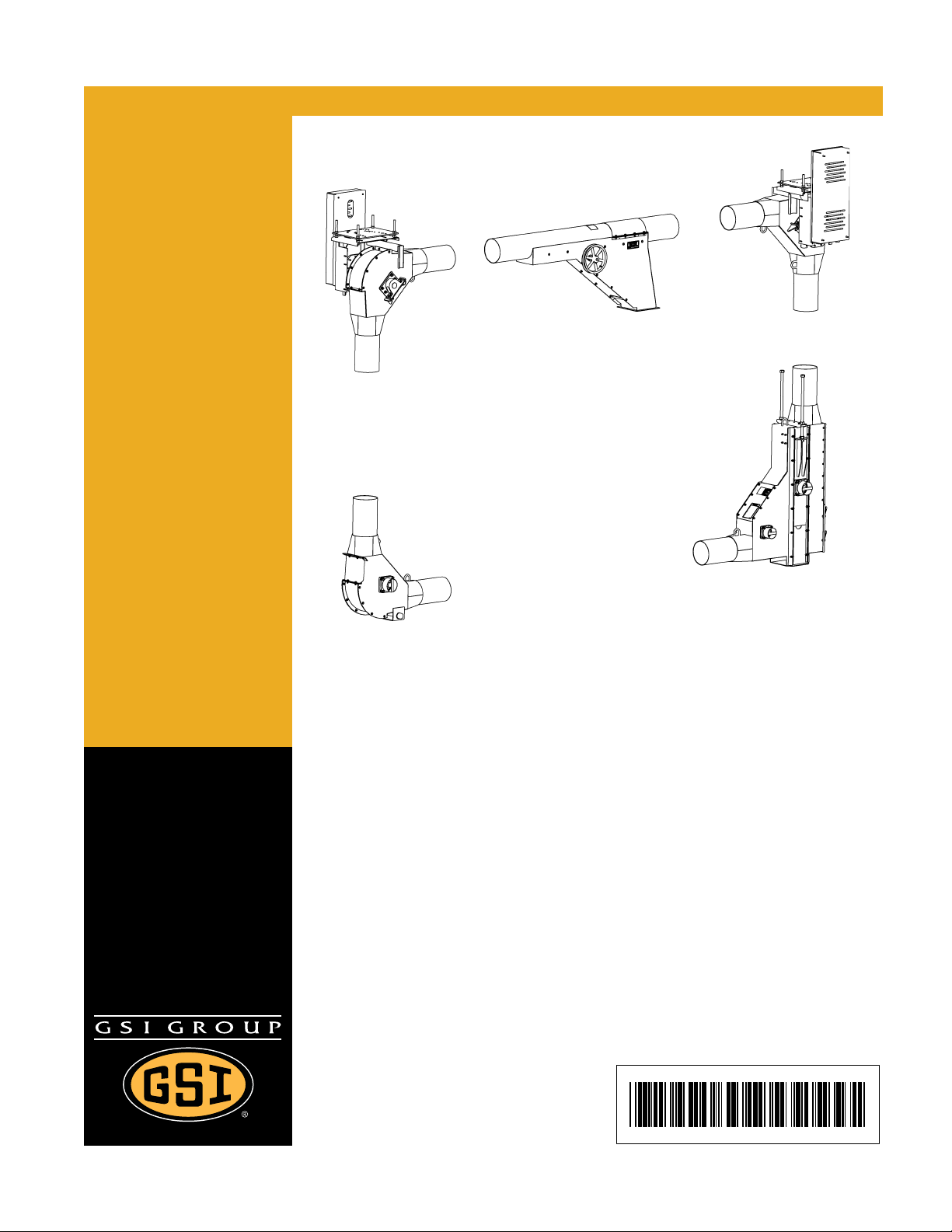
Chain Loop System
without Controls
Owner ’s Manual
PNEG-1128
Date: 07-26-13
Page 2

2 PNEG-1128 Chain Loop System without Controls
Page 3

Table of Contents
Contents
Chapter 1 Safety ..................................................................................................................................................... 5
Safety Guidelines .................................................................................................................................. 5
Safety Instructions ..................... ... .... .......................................... ... ........................................................ 6
Grain Bin Safety ............................... ... ... ... ... ......................................................................................... 9
Chapter 2 Decals .................................................................................................................................................. 10
Decal Placement ........................................................................................................................... ...... 11
Chapter 3 Information .......................................................................................................................................... 13
Chain Loop System Information .......................................................................................................... 13
Final Inspection Check List ................................................................................................................. 14
Chapter 4 Operation ............................................................................................................................................ 15
Operating the Chain Loop System ... ... ... ... ... .... ... .......................................... ... ... .... ... ... ... ... .... ... ......... 15
Chapter 5 Management and Maintenance ......................................................................................................... 17
Maintenance ..................................... ............ ............. ................. ............ ............. ....................... ... ... ... 17
Chain and Paddles .............................................................................................................................. 18
Chapter 6 Installation .......................................................................................................................................... 19
Tube and Corner Assembly ............................................................................................................. ... 21
Drive Assembly ................................................................................................................................... 22
Chain Loop Torque Arm Repair Kit ..................................................................................................... 23
Drive Box Assembly Instructions ......................................................................................................... 26
Discharge with Gate Assembly ........................................................................................................... 27
Unload Well Installation ....................................................................................................................... 28
Chain and Paddles .............................................................................................................................. 29
Inspection Corner ................................................................................................................................ 31
Ground Control Kit for Discharge Gates ............................................................................................. 32
Inlet Dump Hopper Assembly ............................................................................................................. 36
Chapter 7 Troubleshooting ................................................................................................................................. 38
Chapter 8 Component Dimensions .................................................................................................................... 39
8", 10" and 12" Component Dimensions ............................................................................................. 39
8", 10" and 12" Bin Well and Dump Hopper Dimensions .................................................................... 41
PNEG-1128 Chain Lo op System without Controls 3
Page 4

Table of Contents
Chapter 9 Parts List ............................................................................................................................................. 44
8" and 10" Chain and Paddles ............................................................................................................ 46
12" Chain and Paddles (8120141) ...................................................................................................... 47
8" and 10" Discharge Gate .................................................................................................................. 48
12" - (7 Gauge) Discharge Gate (8120194) ................... ... ... ... .... ... ... ... ... .... ... ... ... .... ... ... ... ... .... ... ... ... .. 49
12" - (10 Gauge) Discharge Gate (8120090) ...................................................................................... 50
Chain Loop Drive Components ........................................................................................................... 52
8" (15 HP) Drive Components (8081365) ........................................................................................... 55
8" (20 HP) Drive Components (8081363) ........................................................................................... 56
8" (15 HP-20 HP) Drive Components (8081362) ................................................................................ 57
10" (20 HP) Drive Components (8101526) ......................................................................................... 58
10" (15 HP-20 HP) Drive Components (8101525) .............................................................................. 59
8" (25 HP-30 HP) Drive Components (8081360) ................................................................................ 60
8" (25 HP-30 HP) Drive Components (8081359) ................................................................................ 61
10" (25 HP-30 HP) Drive Components (8101517) .............................................................................. 62
10" (25 HP-30 HP) Drive Components (8101516) .............................................................................. 63
10" (40 HP) Drive Components (8101513) ......................................................................................... 64
10" (50 HP) Drive Components (8101514) ......................................................................................... 65
10" (40 HP-50 HP) Drive Components (8101511) .............................................................................. 66
8" (15 HP) Drive Components (8081271) ........................................................................................... 67
8" (20 HP) Drive Components (8081285) ........................................................................................... 68
8"-10" (25 HP-30 HP) Drive Components (8081296) .......................................................................... 69
10" (40 HP) Drive Components (8101303) ......................................................................................... 70
10" (50 HP) Drive Components (8101331) ......................................................................................... 71
Belt Guard Assembly TA3 (8120217) ................................................................................................. 72
Belt Guard Assembly TA4 (8120211) ................................................................................................. 74
Belt Guard Assembly TA5 (8120214) ................................................................................................. 75
12" 7 Gauge (30 HP) Drive Components (8120000) ........................................................................... 76
12" 7 Gauge (40 HP-50 HP) Drive Components (8120144) ............................................................... 78
12" 7 Gauge (60 HP) Drive Components (8120163) ........................................................................... 80
12" 10 Gauge (30 HP) Drive Components (8120175) ......................................................................... 82
12" 10 Gauge (40 HP-50 HP) Drive Components (8120179) .................................. ... ... ... ... .... ... ... ... .. 84
12" 10 Gauge (60 HP) Drive Components (8120180) ......................................................................... 86
8" and 10" Inlet Dump Hoppers ........................................................................................................... 88
12" (7 Gauge) 42-1/2" Inlet Dump Hoppers (8120121) ....................................................................... 89
12" (7 Gauge) 102-1/2" Inlet Dump Hoppers (8120127) ......... .... ... ... ... ... .... ... ... ... .... ... ... ... ... .... ... ... ..... 90
12" (7 Gauge) 122-1/2" Inlet Dump Hoppers (8120134) ......... .... ... ... ... ... .... ... ... ... .... ... ... ... ... .... ... ... ..... 91
12" (10 Gauge) 42-1/2" Inlet Dump Hoppers (8120185) ......... .... ... ... .......................................... ... ... .. 92
12" (10 Gauge) 102-1/2" Inlet Dump Hoppers (8120186) ................................................................... 94
12" (10 Gauge) 122-1/2" Inlet Dump Hoppers (8120187) ................................................................... 95
8" and 10" Standard Corner ................................................................................................................ 96
12" (7 Gauge) Standard Corner (8120031) ......................................................................................... 98
12" (10 Gauge) Standard Corner (8120176) ........................ ............................................. ................ 100
8" and 10" Inspection Corner ............................................................................................................ 102
12" (7 Gauge) Inspection Corner (8120051) .................................. ... ... ... .... ...................................... 104
12" (10 Gauge) Inspection Corner (8120177) ................................................................................... 106
Chain Loop Torque Plate Assembly .................................................................................................. 108
Chapter 10 Warranty .......................................................................................................................................... 109
4 PNEG-1128 Chain Loop System without Controls
Page 5
1. Safety
DANGER
WARNING
CAUTION
NOTICE
This is the safety alert symbol. It is used to alert you
to potential personal injury hazards. Obey all safety
messages that follow this symbol to avoid possible
injury or death.
WARNING indicates a hazardous situation which, if not
avoided, could result in death or serious injury.
CAUTION, used with the safety alert symbol, indicates a
hazardous situation which, if not avoided, could result in
minor or moderate injury.
NOTICE is used to address practices not related to
personal injury.
DANGER indicates a hazardous situation which, if not
avoided, will result in death or serious injury.
Safety Guidelines
This manual contains information that is important for you, the owner/operator, to know and understand.
This information relates to protecting personal safety and preventing equipment problems. It is the
responsibility of the owner/operator to inform anyone operating or working in the area of this equipment
of these safety guidelines. To help you recognize this information, we use the symbols that are defined
below. Please read the manual and pay attention to these sections. Failure to read this manual and its
safety instructions is a misuse of the equipment and may lead to serious injury or death.
PNEG-1128 Chain Loop System without Controls 5
Page 6
1. Safety
Follow Safety Instructions
Carefully read all safety messages in this manual and
safety signs on your machine. Keep signs in good
condition. Replace missing or damaged safety signs. Be
sure new equipment components and repair parts include
the current safety signs. Replacement safety signs are
available from the manufacturer.
Learn how to operate the machine and how to use controls
properly. Do not let anyone operate without instruction.
Keep your machinery in proper working condition.
Unauthorized modifications to the machine may impair
the function and/or safety and affect machine life.
If you do not understand any part of this manual or need
assistance, contact your dealer.
Read and Understand Manual
Operate Motor Properly
In an emergency, shut down the power source.
Turn OFF and lock out all power sources before performing
any maintenance.
Do not operate electric motor equipped units until motors are
properly grounded.
Disconnect power on electrical driven units before resetting
motor overloads.
Do not repetitively stop and start the drive in order to free a
plugged condition. Jogging the drive in this manner can damage
the equipment and/or drive components.
Electric Shock Hazard
Safety Instructions
Our foremost concern is your safety and the safety of others associated with this equipment. We want to
keep you as a customer. This manual is to help you understand safe operating procedures and some
problems which may be encountered by the operator and other personnel.
As owner and/or operator, it is your responsibility to know what requirements, hazards and precautions
exist, and to inform all personnel associated with the equipment or in the area. Safety precautions may be
required from the personnel. Avoid any alterations to the equipment. Such alterations may p roduce a very
dangerous situation where SERIOUS INJURY or DEATH may occur.
This equipment shall be installed in accordance with the current installation codes and applicable
regulations which should be carefully followed in all cases. Authorities having jurisdiction should be
consulted before installations are made.
6 PNEG-1128 Chain Loop System without Controls
Page 7
1. Safety
Stay Clear of Moving Parts
Entanglement in rotating impeller arms will cause serious injury
or death.
Keep all shields and covers in place at all times.
Wear close fitting clothing. S top and lock out power source before
making adjustments, cleaning, or maintaining equipment.
Entanglement Hazard
Practice Safe Maintenance
Understand service procedures before doing work. Keep area
clean and dry.
Never lubricate, service, or adjust machine while it is in operation.
Keep hands, feet and clothing away from rotating parts.
Keep all parts in good condition and properly installed. Fix
damage immediately . Replace worn or broken p arts. Remove any
built up grease oil and debris.
Maintain Equipment
and Work Area
Prepare for Emergencies
Be prepared if fire starts.
Keep a first aid kit and fire extinguisher handy.
Keep emergency numbers for doctors, ambulance service,
hospital and fire department near your telephone.
Keep Emergency Equipment
Quickly Accessible
PNEG-1128 Chain Loop System without Controls 7
Page 8
1. Safety
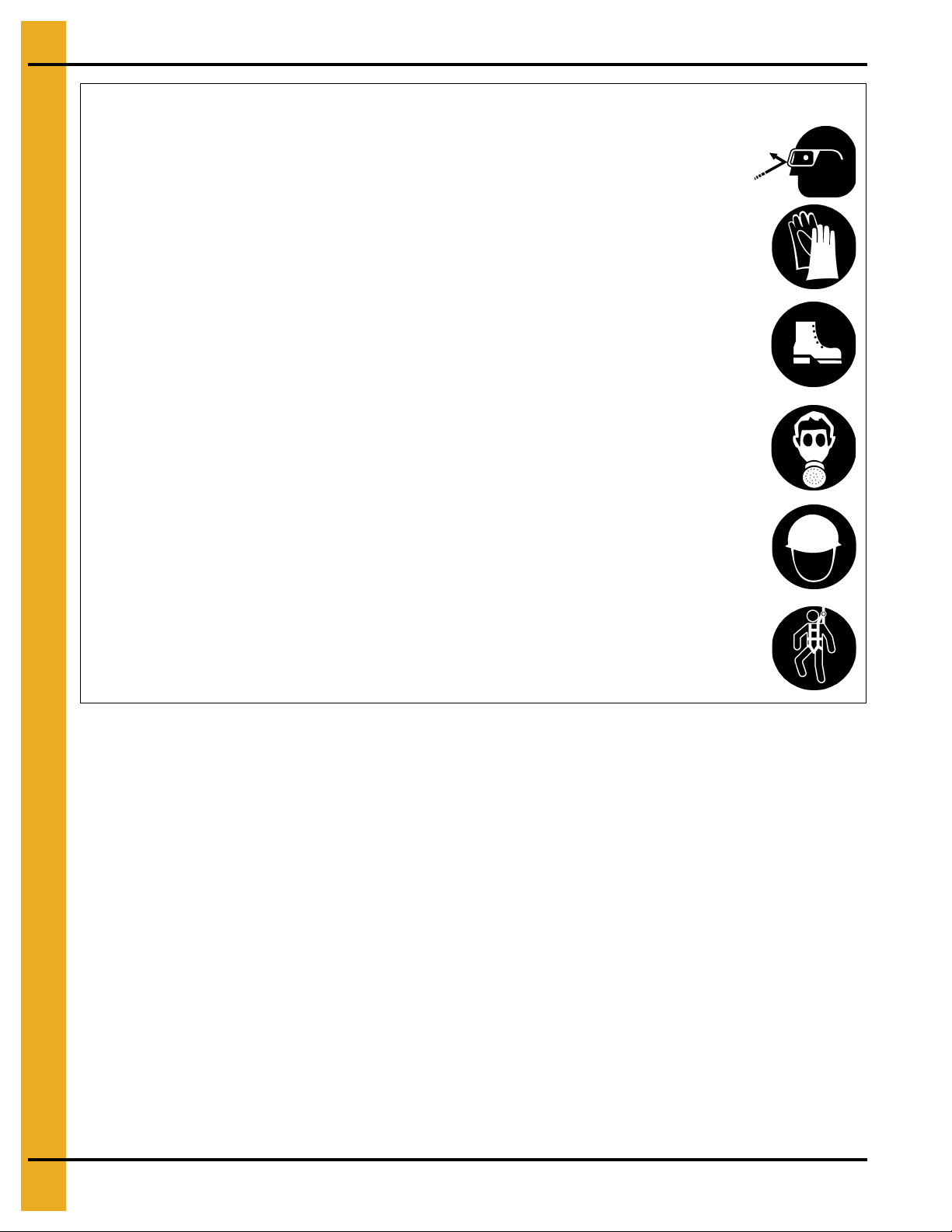
Wear Protective Clothing
Wear close-fitting clothing and safety equipment appropriate
to the job.
Remove all jewelry.
Tie long hair up and back.
Wear safety glasses at all times to protect eyes from debris.
Wear gloves to protect your hands from sharp edges on
plastic or steel parts.
Wear steel-toed boots to help protect your feet from falling
debris. Tuck in any loose or dangling shoestrings.
A respirator may be needed to prevent breathing potentially
toxic fumes and dust.
Wear a hard hat to help protect your head.
Wear appropriate fall protection equipment when working at
elevations greater than six feet (6').
Eye Protection
Gloves
Steel-Toed Boots
Respirator
Hard Hat
Fall Protection
8 PNEG-1128 Chain Loop System without Controls
Page 9
1. Safety
DANGER
DANGERDANGER
DANGERDANGER
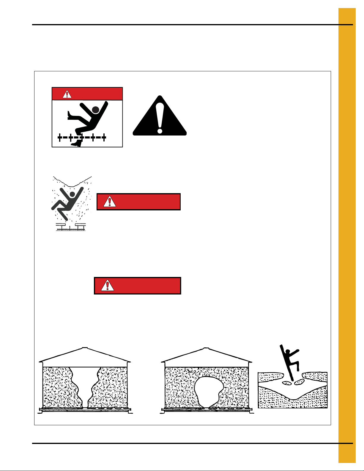
DO NOT ENTER A GRAIN BIN UNLESS POWER
IS LOCKED OUT TO ALL BIN EQUIPMENT.
DO NOT ENTER A GRAIN BIN IF THE GRAIN HAS
BRIDGED OR STOPPED FLOWING NORMALLY. THE
GRAIN CAN COLLAPSE WITHOUT WARNING AND
CAN TRAP, BURY AND CAUSE SUFFOCATION.
DO NOT ENTER A GRAIN BIN WHILE GRAIN IS
BEING REMOVED. FLOWING GRAIN CAN
TRAP, BURY AND CAUSE SUFFOCATION.
Grain Bin Safety
The Chain Loop System is generally used to move grain into or from grain bins. Be aware of the dangers
inherit in grain bins.
DANGER
PNEG-1128 Chain Loop System without Controls 9
Page 10
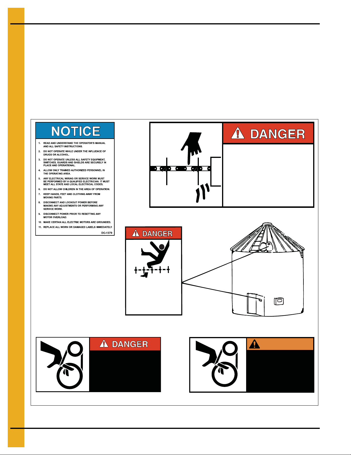
2. Decals
8107006
MOVING CHAINS AND PADDLES!
THIS BIN IS EQUIPPED WITH A CHAIN LOOP SYSTEM
WHICH CAN KILL OR DISMEMBER.
KEEP CLEAR OF ALL CHAIN AND PADDLES AND
NEVER ENTER THIS BIN UNLESS ALL POWER IS
DISCONNECTED AND LOCKED OUT.
FAILURE TO DO SO WILL RESULT IN SERIOUS INJURY
OR DEATH!
SHEAR POINT
Keep hands clear of moving
parts. Do not operate with
guard removed. Disconnect
and lockout power before
servicing.
DC-994
SHEAR POINT
Keep hands clear of moving
parts. Do not operate with
guard removed. Disconnect
and lockout power before
servicing.
DC-995
WARNING
This decal is provided in
the Owner’s Manual
Packet. Place on the bin
during Installation.
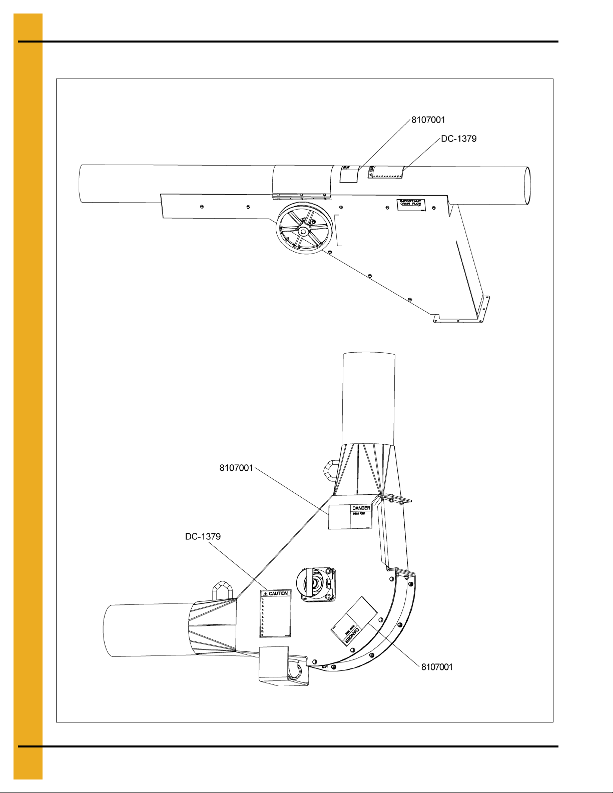
8107001
DC-1379
DC-994
DC-995
8107006
THE DECALS SHOWN ON THIS PAGE MUST BE DISPLAYED AS SHOWN
Replacements are available upon request. Write to the following address:
GSI Decals
1004 E. Illinois St.
Assumption, IL. 62510
Phone: 1-217-226-4421
NOTE: 1. The decals on this page are not actual size.
2. Keep all decals wiped clean at all times.
3. All decals must be replaced if they are destroyed, missing, painted over or can no longer
be read.
SHEAR POINT
Do not operate with cover open.
Keep clear of moving chain and
paddles.
Do not remove or modify guards.
Disconnect and lockout power
before servicing.
Failure to do so will result in
Serious INJURY or DEATH.
8107001
10 PNEG-1128 Chain Loop System without Controls
Page 11
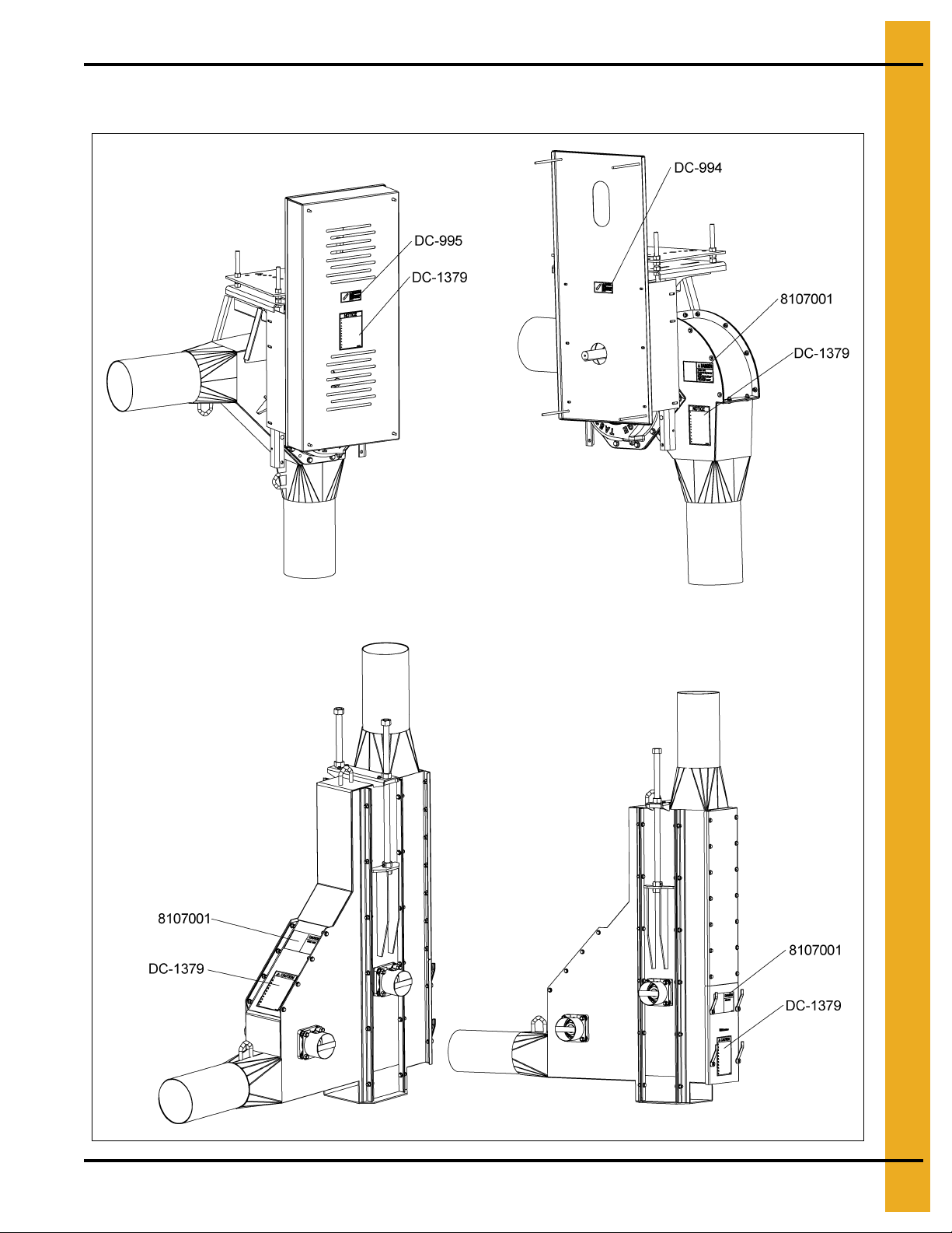
Decal Placement
NOTE: Cover and sheaves removed
for clarity.
2. Decals
PNEG-1128 Chain Loop System without Controls 11
Page 12
2. Decals
Decal Placement
12 PNEG-1128 Chain Loop System without Controls
Page 13
3. Information
Chain Loop System Information
A Chain Loop System is a chain and paddle conveyor moving through a round housing. A loop system
allows you to do total loading and unloading with a single drive. Chain Loop Systems will handle a wide
range of free flowing materials. They are primarily intended for grain and grain products. They will move
material into and out of grain storage structures, vehicles, dryers and other facilities with ease and
gentleness. The Chain Loop System is well suited for blending materials while being transferred from one
storage unit to another.
The height and length of the system is limited by the combined horsepower required to move the grain.
The vertical Chain Loop System requires greater horsepower per foot, so the taller units will be more
limited in the overall horizontal length. System lengths of several hundred feet are common. However,
relatively small systems to accomplish more specific tasks are also available.
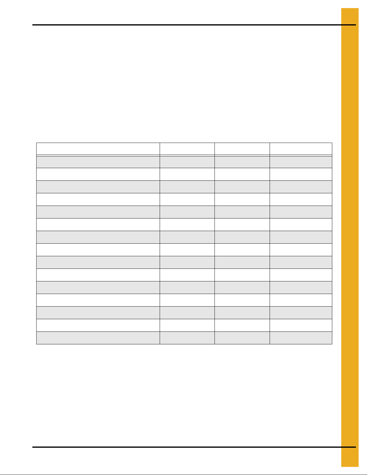
Chain Loop System Specifications
8" 10" 12"
*Maximum capacity in BPH (Tons/Hr) 4000 (100) 6000 (150) 1000 (250)
Chain travel in FPM (Meters, Min) 325 (99) 325 (99) 400 (122)
Head shaft RPM 94 94 83
Corner housing thickness, galvanized (mm) 7 Ga. (4.8) 5 Ga. (4.8) 3/16" (4.8)
Galvanized tubing wall thickness (mm) 12 Ga. (2.7) 12 Ga. (2.7) 10 Ga. (3.47) 7 Ga. (5)
Paddle thickness (UHMW) (mm) 3/8" (9.5) 1/2" (12.7) 1/2" (12.7)
Corner shaft diameter (mm) 2" (50.8) 3" (76.2) 3-7/16" (87.3)
Conveyor chain 81XHH 81XHH 81XHH
Conveyor sprocket 16 Tooth 16 Tooth 22 Tooth
*Power requirements
Per foot vertical (KW/M) 0.35 (0.86) 0.5 (1.22) 0.75 (1.84)
Per foot horizontal (KW/M) 0.08 (0.19) 0.11 (0.27) 0.18 (0.44)
Weight per foot lbs (KG/M)
Empty 12 (17.9) 15 (22.3) 24 (35.8) 30 (44.7)
Full of 56 lb. per bu. material 28 (41.7) 40 (59.5) 59 (88) 65 (97)
* Clean dry grain
PNEG-1128 Chain Loop System without Controls 13
Page 14
3. Information
Final Inspection Check List
The Chain Loop System requires an inspection before start-up after the assembly is complete and before
each use. The following are critical areas to be inspected.
1. Make sure that the main power isolator is locked in the “OFF” position and that the
WARNING
only key is in the possession before removing any shields and inspection covers.
2. Check all safety decals and replace any that are worn, missing or illegib le.
part numbers and location.
3. Check for proper chain tension and adjust if necessary. See Page 29 for full instructions.
4. Check that the discharge gates open and close completely. Remove the inspection cover from the
top of the discharge gate and make sure that the gate is clean inside.
5. Check the lubricant level in the gear reducer at the drive corner. See Page 17 for
lubrication specifications.
NOTE: The gear reducer is shipped dry and needs to be filled to the proper level before use.
6. Check the condition of the drive belts and make sure that they are aligned and tensioned properly.
7. Check that the corner sprockets are centered in the housings. Realign the sprockets and tight en the
set screws if necessary.
8. Check overall structural integrity of the Chain Loop System and make sure that all supports and
components are secure.
9. Check to make sure that the chain moves freely (this is particularly important if the temperature is
below freezing). Use a pipe wrench on the end of each of the corner shafts to manually move
the chain.
10. Make sure all shields and safety guards are in place before restoring power.
See Pages 10-12
for decal
WARNING
14 PNEG-1128 Chain Loop System without Controls
Page 15
4. Operation
Lock out the main power source before removing any inspection covers or
shields necessary to empty the system.
CAUTION
Operating the Chain Loop System
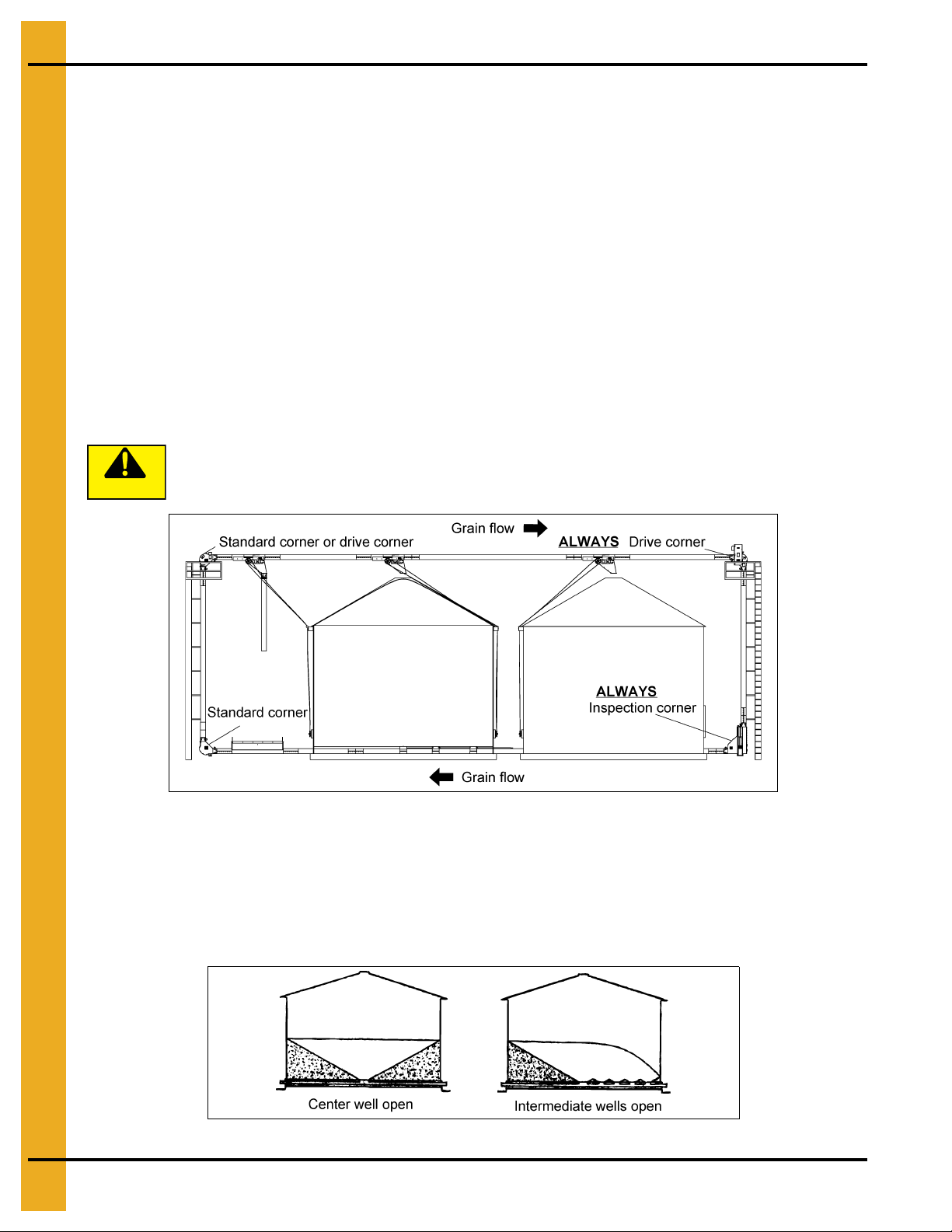
The Chain Loop is generally used to transfer grain to or from storage bins. Grain can be fed into the system
through an inlet dump hopper or through center or intermediate grain wells in the storage b ins. Wells from
more than one bin can be opened at the same time to blend the contents of different bins. The system is
usually oriented vertically (with the tube running under the storage bins), or at an angle with the bottom
tube running along the sides and the top tube running over the fill holes of the storage bins. Horizontal
installations are also possible - check with your dealer for special gear reducer lubrication requirements
for horizontal installations.
The Chain Loop System should always be run under partial load for a period of time to polish the tube
walls before attempting to run at full load. This is especially true when breaking in a new system but equally
important after being idle for a length of time. Observe the amp meter on the drive motor while running
with a partial load until the amperage starts to decline. This is an indication that the tube walls have been
polished enough to handle a larger load.
It is very important to avoid stopping the chain under a loaded condition. Never attempt to restart until the
Loop System has been emptied of as much grain as possible.
CAUTION
Observe the following basic sequence for using the Chain Loop System to fill storage bins.
1. Open the discharge gate above the destination bin.
2. If available, open the discharge gate above a bin downstream from the destin ation bin to be used as
an overflow.
3. Start the Chain Loop drive motor. Station an individual at the control box to observe the amp gauge
of the drive motor.
4. Let grain flow into the inlet dump hopper. Open the flow control by adjusting the chains on the hopper
a small amount at a time to make sure that the amperage does not exceed the capability of the drive
motor. NOTE: Some materials and grains such as soybeans flow very easily, so it is important to
make sure that the center shield in the inlet hopper is adjusted low enough to prevent overloading
the system.
5. Let the Chain Loop run until the system is empty.
6. Close the discharge gates and the dump hopper flow control when through filling.
7. Shut down the drive motor.
8. Make sure to lock out the power source before leaving the work area.
PNEG-1128 Chain Loop System without Controls 15
Page 16
4. Operation
Operating the Chain Loop System (Continued)
Observe the following basic sequence for using the Chain Loop System to transfer grain from
storage bins.
1. Open the discharge gate above the withdrawal bin.
2. Open the discharge gate above the destination bin or truck-loading spout.
3. Start the Chain Loop drive motor. Station an individual at the control bo x to ob serve the amp g auge
of the drive motor.
4. Open the slide gate under the withdrawal bin a little at a time to make sure that the amperage does
not exceed the capability of the drive motor.
5. Close the discharge gate above the destination bin or truck when full. DO NOT SHUT DOWN THE
CHAIN LOOP DRIVE MOTOR AT THIS TIME.
6. Close the slide gate under the withdrawal bin.
7. Run the Loop System until all remaining grain in the tube has been returned to the withdrawal bin.
8. Shut down the drive motor.
CAUTION
A sweep auger may be placed in the bin after all the grain has been removed that will gravity-flow
through the center well. Shut down and lock out all power to the Chain Loop System b efore installing the
sweep auger.
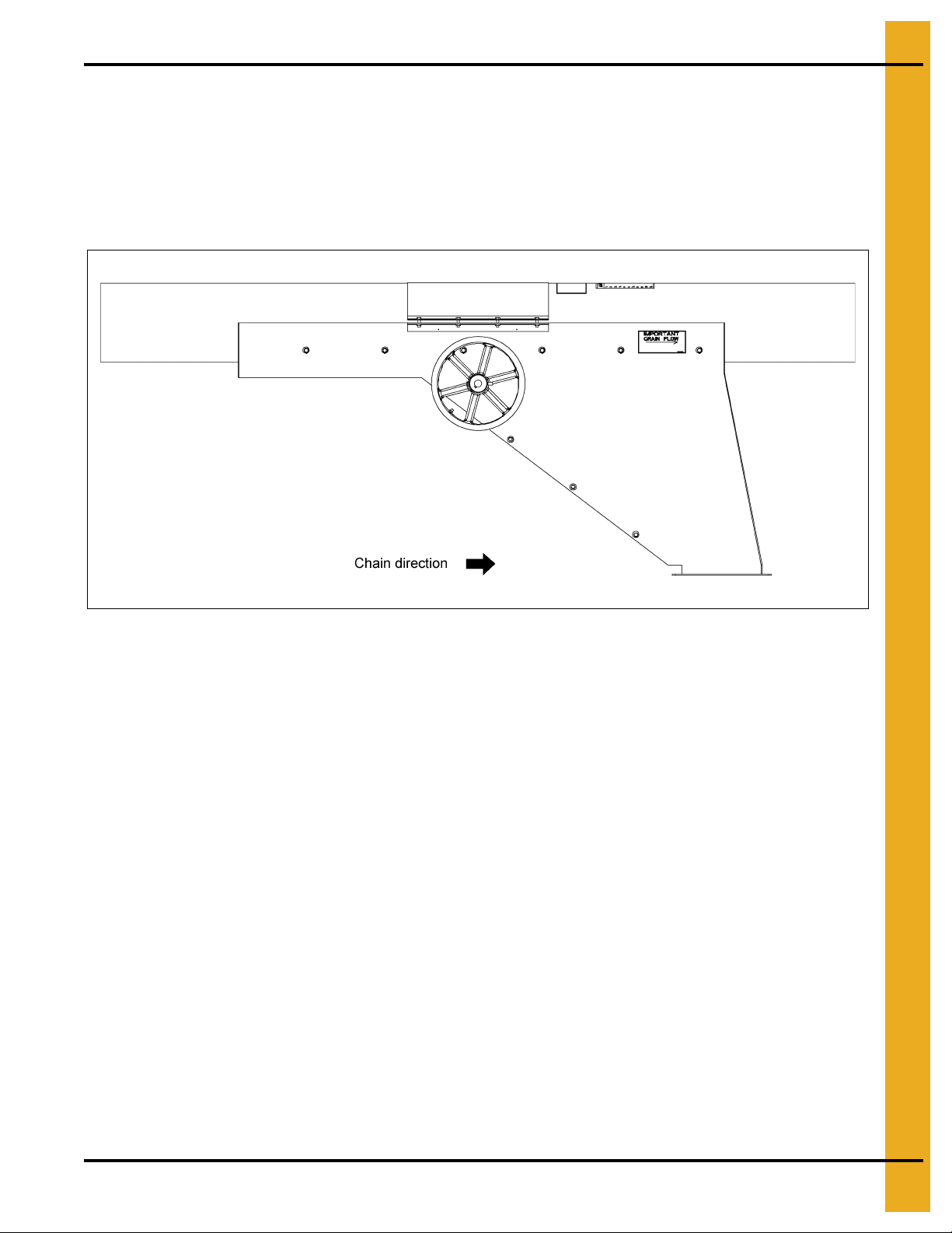
If intermediate bin wells are being used, they should be opened after grain has stopped flowing into the
center well and before the sweep auger is placed in the bin. (See Figure 4B.) Shut down and lock out the
Chain Loop System before installing the sweep auger.
9. Make sure to lock out the power source before leaving the work area.
Figure 4A
Figure 4B
16 PNEG-1128 Chain Loop System without Controls
Page 17
5. Management and Maintenance
CAUTION
Lock out the main power source before performing any maintenance or
service inspections.
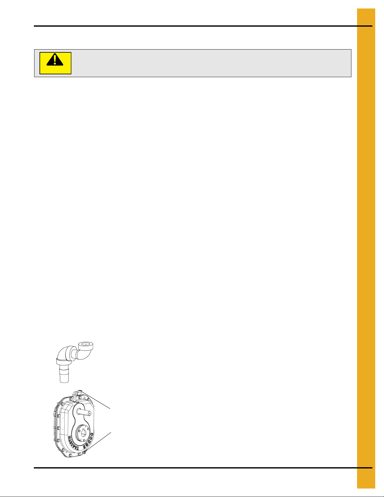
8101333 - 1/2" Vent elbow assembly
(Used on TA 4, TA5 and TA6 reducers in “D” position)
8101335 - 3/8" Vent elbow assembly
(Used on TA3 reducers in “D” position)
To install vent elbow assembly:
(Reducer is shown in “D” position - Input shaft at the top)
• Remove magnetic drain plug from the top of the reducer and replace
with the proper vent elbow assembly.
• Remove vent plug from the bottom of the reducer and replace with
the magnetic drain plug from the top.
• Install the vent plug in the top of the vent elbow assembly.
Maintenance
Dodge Gear Reducer
Use the information that is on the gear reducer nameplate, the warning tags and the Dodge instruction
manual that is included with the Chain Loop manual to determine specific maintenan ce instructions for the
gear reducer used on the system. When referring to the dodge manual, n ote that the reducer is mou nted
in the “D” position on the Chain Loop.
NOTE: The gear reducer is shipped dry and must be filled to the proper level before use.
Use a high-grade petroleum base rust and oxidation inhibited SAE 90 weight gear oil for ambient
temperatures from 15°F to 125°F (-10°C to 52°C). Oils with an “EP” additive are not recommended for
average conditions (see the lubrication section of the dodge manual). Use the check oil plug for
determining the correct amount of oil; too much oil will cause overheating and too little will cause bearing
and gear failure. The approximate quantity of oil for each reducer size is:
Model TA3203H 4.0 qt (3.80L) - for 15-20 HP motors
T A4207H 7.3 qt (6.90L) - for 25-30 HP motors
TA5215H 12.9 qt (12.2L) - for 40 HP motors
TA6307H 15.8 qt (15.0L) - for 60 HP motors
The oil should be changed at the beginning of every harvesting season if the Chain Loop is used for
seasonal grain handling. It should be changed after 2500 hours of operation or every 6 months if used
under average industrial conditions. The oil should be changed more frequently if used under extreme
operating conditions such as large changes in ambient temperatures, dust, dirt, chemical particles,
chemical fumes or oil sump temperatures above 200°F.
Drain the reducer, clean the magnetic plug and flush with kerosene before refilling with new oil.
Drive Belts
Check to make sure that drive belts are tensioned and aligned properly. Use a straight edge to check the
alignment with the motor and reducer sheaves. Adjust all the motor tensioning rods equally to keep the
motor shaft parallel to the reducer shaft.
Vent Elbow Installation Instructions
PNEG-1128 Chain Loop System without Controls 17
Page 18

5. Management and Maintenance
Chain and Paddles
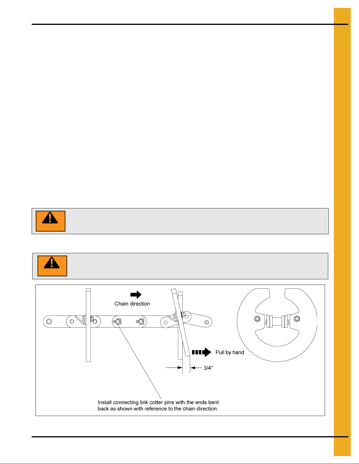
Check for proper chain tension. Open the inspection door at the inspection corner and check chain tension
by pulling the bottom edge of a paddle by hand. The paddle tip sho uld not move more than 3/4" when the
chain is properly tensioned. (See Page 29.)
The Chain Loop chain has connecting links spaced every 10'. Check these links to make sure that they
are securely fastened and that the cotter pins are bent back correctly. (See Figure 6M on Page 30.)
Check the lock nuts used to fasten the paddles to the chain brackets. They should be tightened to a torque
specification of 20 ft. lbs. (2.8 KG-M or 26 N-M).
Adjust the chain tension by loosening the locking jam nuts on the adjusting screw and turning the screw
to move the inspection corner sprocket. Turning the adjusting screw clockwise will tighten the chain and
turning it counterclockwise will loosen the chain. Remove chain links if there is not enough travel in the
adjusting screw to tighten the chain. Adjust each side equally to keep the sprocket shaft square with the
corner housing. (See Figure 6N on Page 31.)
Spray a light coating of oil on the chain after a season of use.
Corner Shaft Bearings
The bearings for the corner sprockets are sealed bearings and require only a small amount of
multi-purpose grease every 50 hours. Check bearings for wear and that the locking collars are secure.
Corner Sprockets
Inspect the condition of corner sprockets for teeth wear and that they are centrally aligned in each of the
corner housings.
18 PNEG-1128 Chain Loop System without Controls
Page 19
6. Installation
It is expected that an experienced millwright or contrac tor will provide the supporting structure and
do the installation of a Chain Loop System including the electrical wiring and the control box.
All electrical wiring and controls should be in accordance with local regulations (BS767: 1992 or the
National Electric Code).
NOTE: It is recommended that an amp meter for the drive motor be installed close to the inlet hopper so
an operator can easily monitor and avoid overloading the system.
The supporting structure needs to comply with local wind loads and soil supporting requirements as well
as support the weight of the Chain Loop System. Component weights full of grain are:
System Size Tube (Full) Discharge Gate Standard Corner Drive Corner
8" 29 lbs/ft (43.1 KG/M) 411 lbs. (187 KG) 342 lbs. (155 KG) 1 103 lbs. (502 KG)
10" 40 lbs/ft (59.5 KG/M) 533 lbs. (242 KG) 489 lbs. (222 KG) 1394 lbs. (634 KG)
12" 10 Gauge 59 lbs/ft (88 KG/M) 1024 lbs. (466 KG) 919 lbs. (418 KG) 2406 lbs. (1094 KG)
12" 7
Gauge 65 lbs/ft (97 KG/M) 1084 lbs. (493 KG) 933 lbs. (424 KG) 2420 lbs. (1101 KG)
NOTE: Each calculation includes the respective chain.
A layout should be drawn to show the exact location of grain bins, inlets, outlets, the control box, outlet
control kits, the power source and the supporting structure. The layout should consider future expansion,
the ability to mix grains from several locations, the grain direction, the operation of slide gates, the use of
other conveyors to fill or unload bins and whether the Chain Loop tube is under the center of or beside the
grain bins. Chain Loop Systems are provided with one (1) or two (2) drive corners depending on the power
requirements of each system. Drive corners are always located at the upper corners, and the drive corner
for single drive systems must be located at the far end of the top chain run. This will allow the drive corner
to pull grain up from the loading hopper and across the top to the storage bins. The inspection corner is
always located on the ground furthest from the loading hopper. This allows proper chain
tensioning throughout the system. (See Figure 4A on Page 16.)
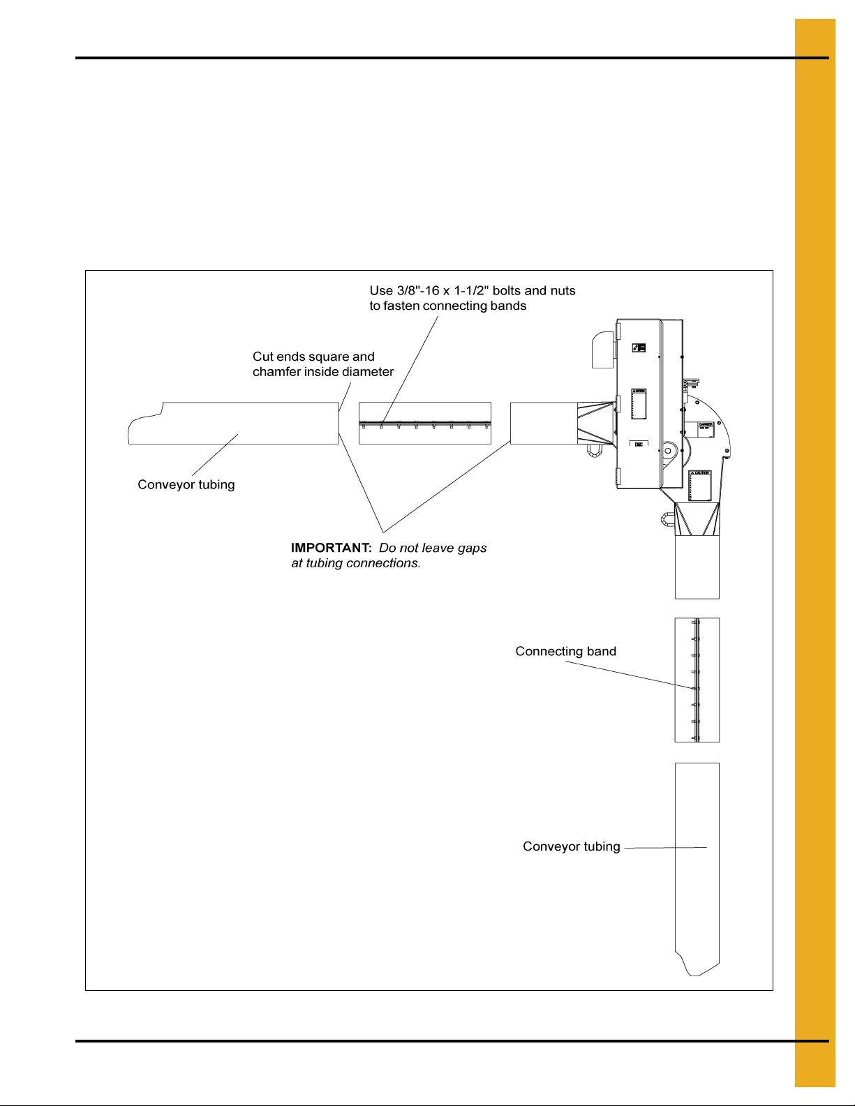
It is important to slide components together tightly and to have the clamping band centered on the joint
before tightening the bands. All cuts should be made square and the inside diameter chamfered to ensure
that the ends butt together tightly during assembly. Even small gaps left in the tubing system during
assembly will gradually close during operation of the Chain Loop causing the chain to require frequent
inspection and tightening. (See Page 21.)
General guidelines to consider are:
1. The Chain Loop will move grain in one direction only; it is not reversible.
2. Provide room for service and maintenance at each of the corners and discharge gates.
3. Avoid having any part of the system under grade to eliminate water accumulation problems.
4. Provide adequate footings for solid supporting structures.
5. Minimize the loaded distance by placing the inlet hopper as close to the vertical tube as possible.
6. There can be no twist in the chain/paddles. The opening should be oriented so that the open side of
the paddle will pass across the sprockets.
PNEG-1128 Chain Loop System without Controls 19
Page 20
6. Installation
System Size Vertical Factor Horizontal Factor
8" 0.35 HP/loaded foot (0.86 Kw/M) 0.08 HP/loaded foot (0.19 Kw/M)
10" 0.50 HP/loaded foot (1.22 Kw/M) 0.11 HP/loaded foot (0.27 Kw/M)
12" 0.75 HP/loaded foot (1.84 Kw/M) 0.18 HP/loaded foot (0.44 Kw/M)
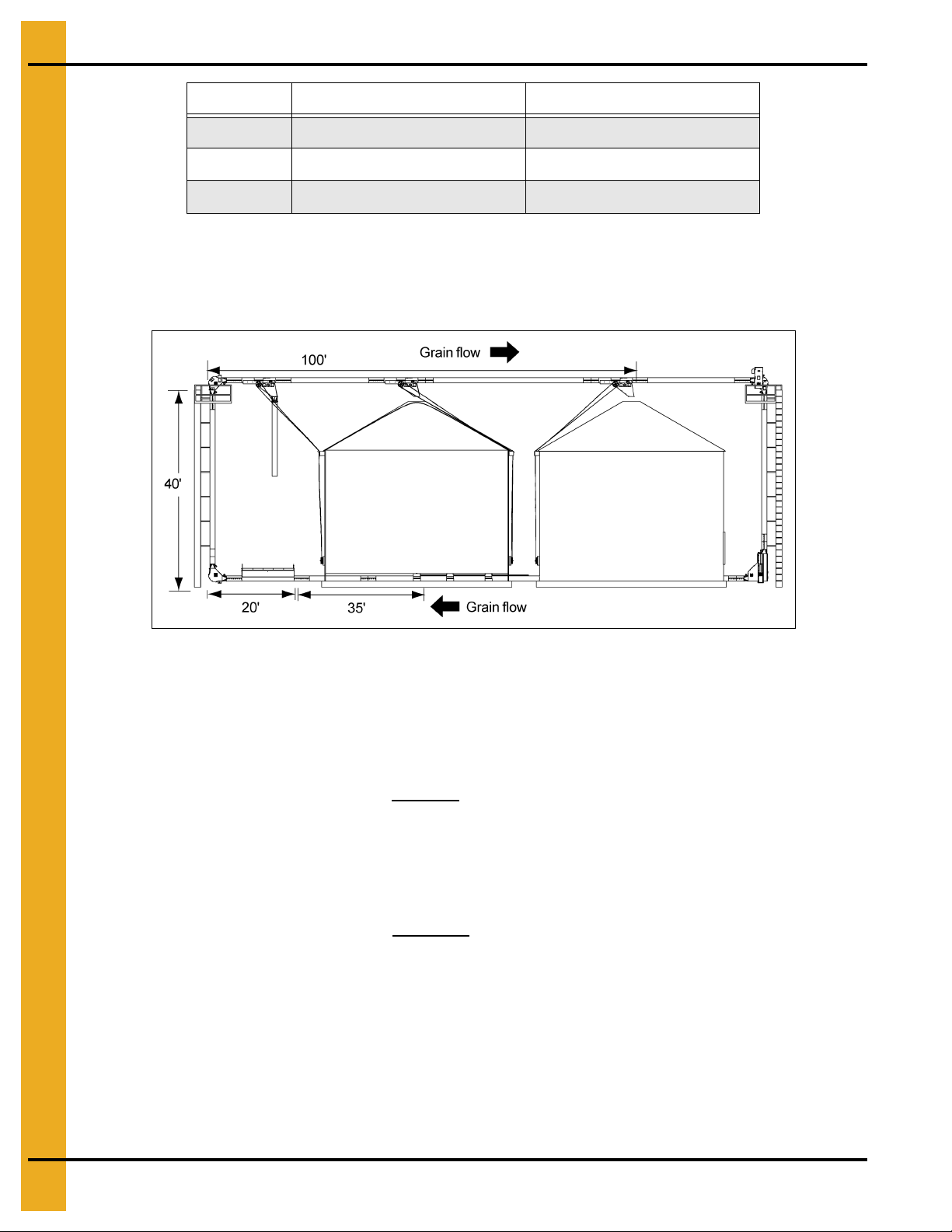
The system should be designed to minimize the distance grain must be moved. The example shows the
dump hopper located next to the vertical tube. If it were located on the other side of the grain bins
then the system would have to move grain that much farther before taking it up and over to the
discharge gates.
Figure 6A
This example illustrates a system and the power requirements for different functions of a Chain
Loop System.
If the main requirement is maximum filling rate, then the motor size for this 8" system would be:
0.35 HP/ft x 40 vertical ft. = 14 HP plus
0.08 HP/ft x (20 + 100 horizontal ft.) = 9.6 HP
= 23.6 (Use a 25 HP motor)
If the requirement is maximum flow rate while moving grain from bin to bin as well as a maximum filling
rate, then the motor size would be:
0.35 HP/ft x 40 vertical ft. = 14 HP plus
0.08 HP/ft x (35 + 20 + 100 horizontal ft.) = 12.4 HP
= 26.4 (Use a 30 HP motor)
20 PNEG-1128 Chain Loop System without Controls
Page 21
6. Installation
Tube and Corner Assembly
Lay the sections out in order so as to determine what portions to assemble prior to actual placement in
the system.
When cutting tubes to exact length, the ends must be cut square and any burrs on the ends must be
removed by chamfering the inside diameter. Join tube and corner components together with connecting
bands. Slide the tube sections tight together and space the connecting band in equal amounts on both
parts of the connection. Tighten the bolts in the band.
Fasten the discharge in place within the tube with connecting bands.
Figure 6B
PNEG-1128 Chain Loop System without Controls 21
Page 22
6. Installation
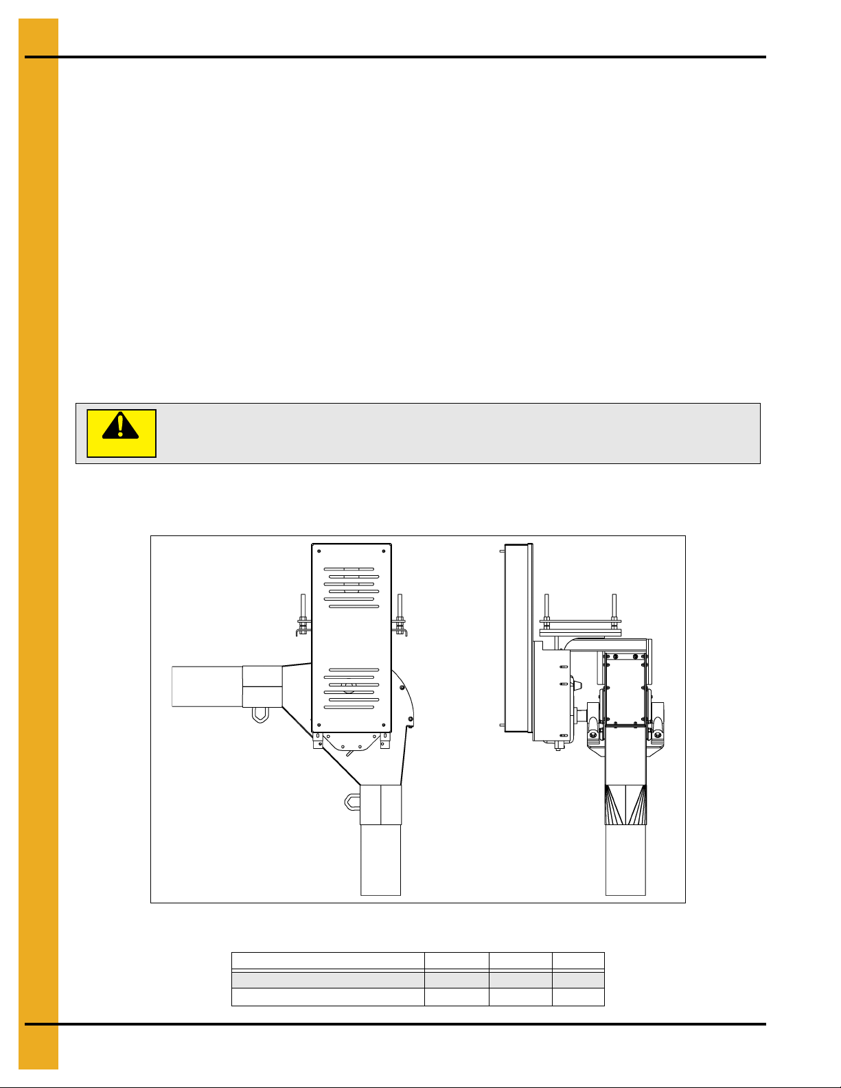
CAUTION
Keep all safety shields and devices in place.
Drive Assembly
The Chain Loop System is powered by an electric 1750 RPM motor.
IMPORTANT: Use the proper size motor to ensure satisfactory operation. Too small of a motor will not
supply the horsepower required to achieve capacity and damage to the motor may occur.
Too large of a motor may cause high stress on components resulting in shorter life.
See Page 13 for motor size specifications.
IMPORTANT: Use the motor sheave furnished. If other size sheaves are used or substituted, improper
chain speed and unsatisfactory operation will result.
Mount the sheaves as close to the belt guard back as possible. Align sheaves by using a straight edge,
placed across the outer faces of both sheaves. Secure in place using taper lock bushing. Be sure drive
keys are properly installed. Check sheave alignment again after sheaves are secured to shafts.
Install the belts onto the sheaves and set belt tension. To tighten belts, turn the 3/4" nuts on the motor
mount rods to raise the motor mount assembly. Raise all the rods the same distance so the motor mount
assembly is parallel with the top.
Check that all fasteners are tightly secured. Close and fasten belt guard.
The gear reducer is shipped without oil. It is necessary to add the proper amount of oil before running. Use
a high grade petroleum base, rust and oxidation inhibited R and O gear oil. Follow the instructions on the
reducer name plate, warning tags and in the installation manual attached to the reducer.
Figure 6C Sample Drive Assembly
Unit Size 8" 10" 12"
Recommended Chain Speed 325 325 400
Corner Shaft RPM 93 93 83
22 PNEG-1128 Chain Loop System without Controls
Page 23
6. Installation
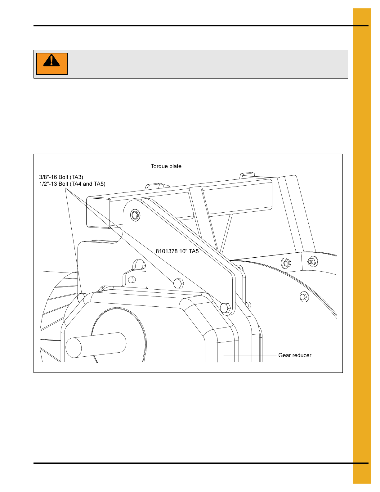
WARNING
Secure the motor mount from both sides to prevent the drive unit from pivoting
either direction on the shaft.
Chain Loop Torque Arm Repair Kit
NOTE: Motor mount and belt guard removed for clarity.
Attach both torque plate assemblies to each side of the gear reducer using the bolts pr ovided. Re-use the
lock washer and hex nut provided with the gear reducer. (See Figure 6D.)
NOTE: Leave the hardware loose to allow for ease of assembly.
TA3 - 3/8"-16 Bolt
TA4 and TA5 - 1/2"-13 Bolt
Figure 6D
PNEG-1128 Chain Loop System without Controls 23
Page 24
6. Installation
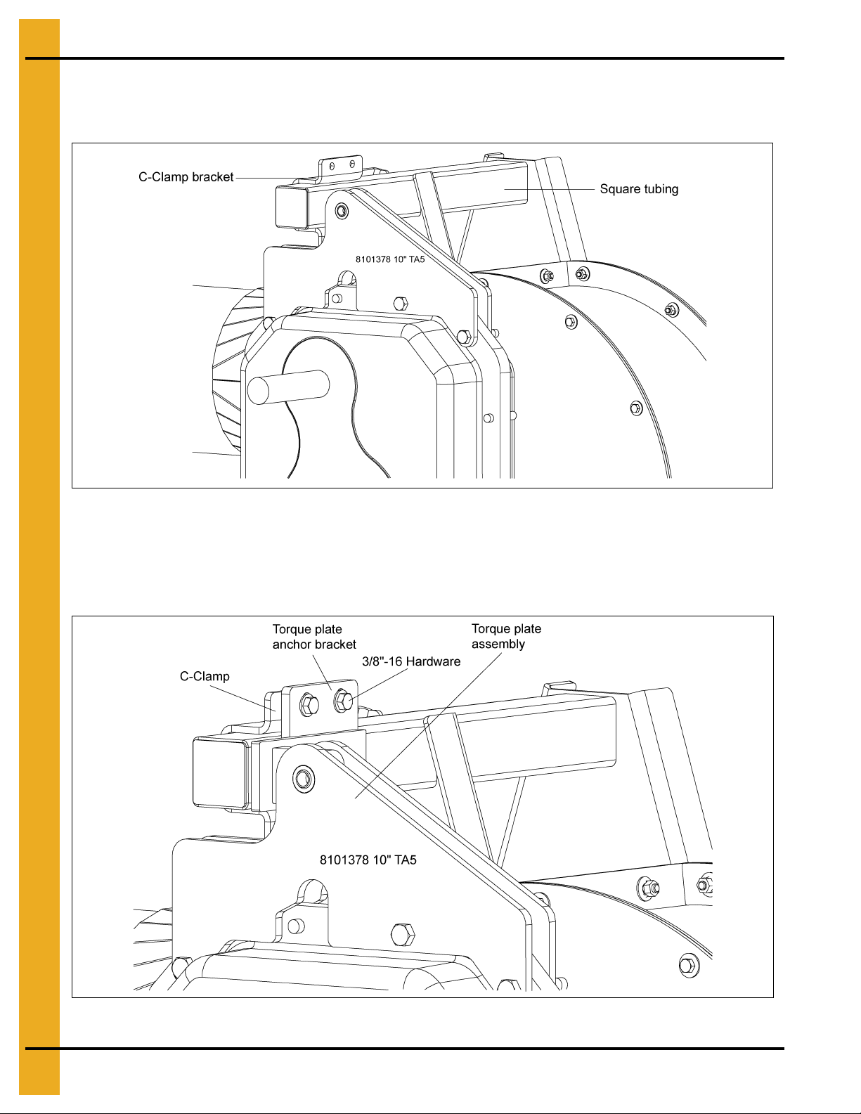
Chain Loop Torque Arm Repair Kit (Continued)
Place the C-clamp bracket to the back side of the square tubing. (See Figure 6E.)
Figure 6E
Place the torque plate anchor bracket between the torque plate assemblies and attach it to the C-clamp
using the 3/8"-16 hardware. (See Figure 6F.)
NOTE: Leave the hardware loose to allow for ease of assembly.
Figure 6F
24 PNEG-1128 Chain Loop System without Controls
Page 25

6. Installation
Chain Loop Torque Arm Repair Kit (Continued)
Attach the torque plate anchor bracket to the torque plates using the two (2) 1/2" flat washers, shoulder
bolt and 3/8"-16 nylock nut.
Tighten the hardware attaching the torque plate assemblies to the gear reducer after tightening the
shoulder bolt hardware. (See Figure 6G.)
Figure 6G
Move the torque plate anchor bracket on the square tube so the torque plate assemblies are aligned
vertical. Once aligned, the 3/8"-16 hardware attaching the torque plate anchor bracket to the C-clamp can
be tightened. (See Figure 6H.)
NOTE: Washers must be on the outside of each torque plate assembly.
Figure 6H
PNEG-1128 Chain Loop System without Controls 25
Page 26

6. Installation
Drive Box Assembly Instructions
Figure 6I
26 PNEG-1128 Chain Loop System without Controls
Page 27
6. Installation
Discharge with Gate Assembly
The discharge unit includes an 8' long section (12' long in 12" system). Locate the outlet of the discharge
in the desired location. It may be necessary to cut exact lengths of other tube conveyor sections to locate
the discharge unit in its proper place. The discharge with gate is designed for chain travel in only one
direction. Make sure it is oriented properly by comparing the appearance to the diagram or referring to the
decal on the discharge unit. Operation in the wrong direction can cause paddle damage.
Figure 6J
When cutting tubes to exact length, the ends must be cut square and any burrs on the ends must be
removed by chamfering the inside diameter. Join tube and discharge gate together with connecting bands.
Slide the tube sections tightly together and space the connecting band in equal amounts on both parts of
the connection.
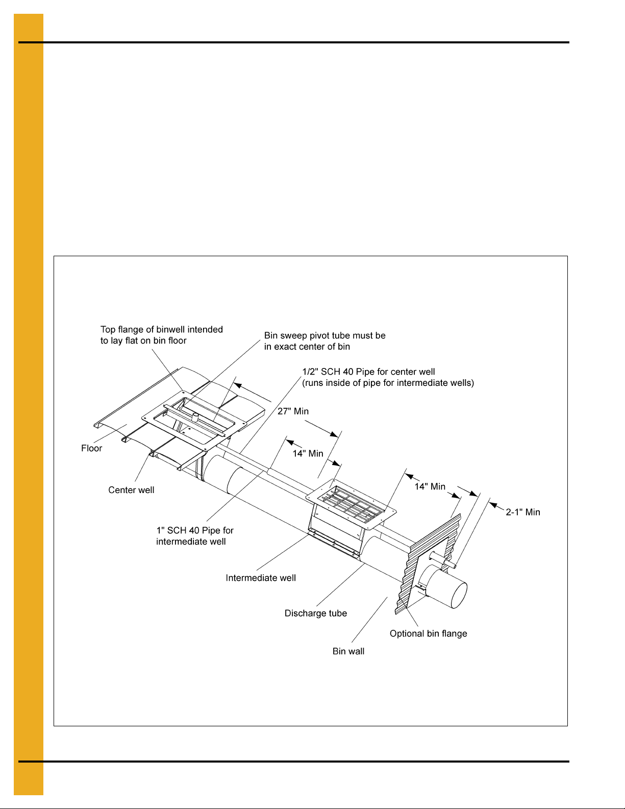
Bin well installation for Chain Loop Systems installed under a row of grain bins.
Position the center bin well so that the bin sweep pivot is at the center of the bin and on top of the Chain
Loop tube. Intermediate wells may be placed on the tube between the center and bin wall if desired.
Use Figure 6K on Page 28 for minimum spacing requirements and as a guide to mark and cut the openings
for the wells in the tube.
NOTE: Do not cut the opening with the chain and paddles inside the tube or they may be damaged.
The control pipe for the center well (1/2" pipe) should fit inside the pipe used for the intermediate wells (1"
pipe). With the center and intermediate wells closed, drill a hole through both control pipes so that a bolt
can be used to lock both pipes together. This will allow both slide gates to be operated together.
Open the slide gate in the center well and withdraw grain until no more flows. Close the center well
slide-gate and place the bolt in the hole drilled through both control rods. The intermediate well
slide-gates can now be operated with the center well.
PNEG-1128 Chain Loop System without Controls 27
Page 28
6. Installation
Unload Well Installation
General Information
Observe the minimum spacings shown in the illustration below. (See Figure 6K.) Wells should be
positioned on the tube so that the gates will open when control pipes are pulled out and away from the
center of the bin.
A control pipe kit may be ordered from your dealer. For the center well, use 1/2" SCH. 40 pipe
(-7/8" O.D.). For the intermediate well(s) use 1" SCH. 40 pipe (-1 3/8" O.D.). It may be necessary to
support the unload well(s) and/or discharge tube from below with blocks or other material.
Consult the manufacturer of the bin floor for information on cutting openings in the floor for unload wells,
for sealing around unload wells and for proper support of the floor around the unload wells and
discharge tube.
Figure 6K
28 PNEG-1128 Chain Loop System without Controls
Page 29
6. Installation
WARNING
Make sure all shields and safety guards are in place before restoring power.
WARNING
Turn OFF and lock out the main power source BEFORE removing any
inspection covers or shields.
Chain and Paddles
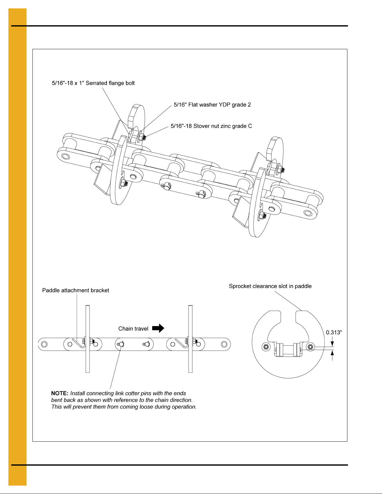
The paddles are attached to the chain with 5/16" x 1" serrated flange bolts, flat washers and locking nuts.
Make sure that the slots in the chain paddle brackets are oriented as shown in Figure 6M on Page 30.
The head of the bolt should be inside the “V” shaped chain paddle bracket and the washer and nut
should be against the face of the plastic paddle. Make sure all hardware is tightened properly to a
torque of 20 ft. lbs.
The chain is shipped in 10' lengths and needs to be spliced as shown in Figure 6M on Page 30. Make sure
to bend the ends of the cotter pins as shown to prevent them from working loose and causing the chain
to break.
Use an electrical fish tape or wire to pull the chain through the tube assembly. It is possible for the chain
to twist a full 360° during this process. Visually check the chain through open inspection covers at the
discharge gates and openings for wells to make sure that this has not happened.
Adjust the tightening screws in the inspection corner all the way up and connect the final chain link through
the access door in the inspection corner after removing as much chain slack as possible. Tighten the chain
by turning the adjusting screws clockwise; adjust each side equally to keep the sprocket shaft square with
the housing. Remove chain links if there is not enough travel in the adjusting screw to tighten the chain.
Make sure that the sprocket shaft is square to the housing by measuring the shaft position on both sides
of the housing. (See Figure 6N on Page 31.)
The chain should be tightened until the paddles are nearly rigid on the chain. The tips of the paddles
should only move 3/4" when grabbed and pulled by hand.
Check and re-tension the chain after the system has been trial run while empty.
Figure 6L
PNEG-1128 Chain Loop System without Controls 29
Page 30
6. Installation
Chain and Paddles (Continued)
Figure 6M Chain and Paddles
30 PNEG-1128 Chain Loop System without Controls
Page 31

Inspection Corner
6. Installation
Figure 6N
PNEG-1128 Chain Loop System without Controls 31
Page 32

6. Installation
Ground Control Kit for Discharge Gates
Determine the best location for each ground control kit. Note that each kit comes with 100' of cable, which
should be adequate for individual bin installations.
The cable idler pulley bracket is usually mounted at the top of the bin wall, just under the roof eave, in line
with the control wheel on the discharge gate. The ground control wheel-mounting bracket should be
mounted to the bin wall directly under the idler pulley bracket at a convenient operating height. It is
important to keep the cable in line with the control wheels on both the discharge gate and at the ground
to avoid having the cable “walk off” either wheel.
The ground control wheel can be mounted to the same bin as the discharge gate, or to an adjacent bin
(See Figure 6O and Figure 6P.)
Figure 6O
Figure 6P
32 PNEG-1128 Chain Loop System without Controls
Page 33

6. Installation
Ground Control Kit for Discharge Gates (Continued)
Each control system should be marked to identify which discharge gate is being controlled.
Each control system should be marked after installation to clearly identify whether the discharge gate is
open or closed.
Set screws in the ground control wheel can be used to lock the wheel in position to prevent accidental
opening or closing of the discharge gate.
Assemble the idler pulleys to the mounting bracket on the inside surface if the cable is going to a discharge
gate on the same bin. Assemble them on the outside if the cable is going to an adjacent bin. Attach the
idler pulley bracket to the bin wall just under the eave to ensure that the cable will clear the bin roof.
Attach the ground control wheel bracket to the bin wall directly below the idler bracket. Assemble the
wheel-mounting bracket loosely to the wall bracket and slide it up as far as possible. Assemble the control
wheel to the shaft and secure with cotter pins. (See Page 35.)
Figure 6Q
PNEG-1128 Chain Loop System without Controls 33
Page 34

6. Installation
Ground Control Kit for Discharge Gates (Continued)
Make sure that the discharge gate is half open and wrap the cable 3-1/2 times around the discharge
gate control wheel. Note that turning the wheel clockwise will close the gate.
Secure the cable to the wheel with the cable clamp by attaching it to the approximate middle of the
3-1/2 wraps of cable. This will ensure that the gate will fully open and close without restriction from the
cable clamped to the wheel.
Make sure that the discharge gate is still half open.
Route the cable back through the right idler pulley and down to the ground control wheel.
At the ground control wheel, turn the wheel until the cable clamp is up and wrap the cable 3-1/2 times
around it.
Secure the cable clamp to the middle wrap.
Splice the ends of the cable with a cable clamp. With the discharge gate half open, the splice should be
at least 5' away from the pulleys and control wheels.
Slide the ground wheel bracket down to take up any slack in the cable and tighten in place.
Check the installation by turning the ground wheel clockwise to fully close the discharge gate and
counterclockwise to fully open the gate without any restrictions from the cable splice or the clamps on the
control wheels.
If the rotation is wrong, then reverse the direction of the 3-1/2 wraps on the ground control wheel.
34 PNEG-1128 Chain Loop System without Controls
Page 35

Ground Control Kit for Discharge Gates (Continued)
6. Installation
Figure 6R Ground Control Kit Parts
Ground Control Kit Parts List
Ref # Part # Description Qty
1 Bolt-Car, Standard Third-Grade 2 3/8"-16 UNC x 0.75, Plated 2
2 8101157 Bracket-Bin Wall Mount Ground Control Kit 1
3 8101158 Bracket-Control Wheel, Weldment Zinc Plated 8101159 1
4 8101156 Bracket-Pulley Mount, Ground Control Kit 1
5 8101153 Control Wheel - w/ Clamp 90° Discharge w/ Gate 1
6 Lock Nut, Flange, 1/4"-20 UNC (Whiz Lock) Plated 8
7 Lock Nut, Flange, 3/8"-16 UNC (Whiz Lock) Plated 2
8 Cotter Pin, Standard 3/16" x 1-3/4" Long 2
9 Pulley-Hot House, (Nolin Milling No #) 2
10 Screw-MF Flange Whiz Lock 1/4"-20 UNC x 3/4", Plated 8
11 Screw - s/ Drill, WH Hex Head 1/4"-14 x 1", (Tek 3) Plated 12
12 Flat Washer, Standard 3/8", Plated 2
13 Flat Washer, Standard 1", Plated 2
PNEG-1128 Chain Loop System without Controls 35
Page 36

6. Installation
See Page 37 for
further detail
Inlet Dump Hopper Assembly
The dump hopper will include a length of tubular conveyor from 6' to 11' depending on the length of d ump
hopper selected. It will also include a top safety screen or drive over grating. Th ere is a grain flow control
inside the hopper that is adjustable using chains mounted at each end. A dump hopper is to receive grain
into the Chain Loop System and should be located at a point along the bottom conveyor portion. Usually
dump hoppers are located near the standard corner where the chain and paddles turn to carry grain up.
For drive over systems, the grate must be supported by a concrete structure. (See Figure 6S.)
Figure 6S
A hopper with top safety screen may be used in non-drive over situations. The top safety screen will not
support vehicles. Make sure either the top safety screen or drive-over grating is in place on the hopper.
Fasten the inlet dump hopper assembly in place within the tubular conveyor with connecting bands.
Figure 6T
NOTE: When the system is not in use, it is a good practice to cover the hopper with a rubber mat to help
keep water, animals and debris out.
36 PNEG-1128 Chain Loop System without Controls
Page 37

6. Installation
Figure 6U
PNEG-1128 Chain Loop System without Controls 37
Page 38

7. Troubleshooting
1. Chain is slipping on the drive sprocket
a. Check the chain tension and tighten at the inspection corner if necessary.
b. Check for obstructions in the system. The paddles may be catching at joints in the tubing.
c. Check to make sure that the sprockets are centered in the corner housings.
d. Avoid starting the system under load. Let the system run until empty before shutting down. If shut
down does occur while the system is loaded, remove as much grain as possible and turn the
corner sprockets by hand with a pipe wrench to loosen the chain before turning the power
back ON.
2. Grain recycling back to the fill point
a. Check to make sure that the discharge gate is open.
b. Check and clean out the slide gate in the discharge gate.
c. Chain speed may be too fast. The drive corner shaft speed should be 94 RPM.
3. Drive belts are slipping
a. Check the drive motor amperage and make sure that the motor is not overloaded.
b. Tighten belts if slippage occurs when the drive motor is not fully loaded.
4. System is not delivering full capacity
a. Make sure that grain is not over running the discharge gate and returning to the fill-point.
b. Chain speed may be too slow. The drive corner shaft speed should be 94 RPM.
c. High moisture grain will move at a lower capacity than dry grain.
d. Check for obstructions in the inlet hopper.
e. Check to make sure that the chain has not been installed with a twist. (See Page 29.)
5. Paddles breaking
a. Check to make sure that the sprockets are centered in the corner housings.
b. Avoid starting the system under load. Let the system run until empty before shutting down.
If shut down does occur while the system is loaded, remove as much grain as possible and
turn the corner sprockets by hand with a pipe wrench to loosen the chain before turning the power
back ON.
c. Check to make sure that the paddles are fastened securely to the chain brackets.
d. Let the system “break-in” and the tubing become polished before loading to full capacity.
e. If you hear paddles “clicking” at a joint, check for gaps in the tubing. This will require loosening the
bolts in the connecting band to be able to see the tube joint.
6. Chain failure
a. Check to make sure that the master connecting links have been installed correctly.
(See Figure 6M on Page 30.)
b. Check for obstructions in the system.
c. Avoid starting the system under load. Let the system run until empty before shutting down.
38 PNEG-1128 Chain Loop System without Controls
Page 39

8", 10" and 12" Component Dimensions
Figure 8A
Drive Corners
Horse Power 8" System 10" System 12" 10 Gauge 12" 7 Gauge
15 8081365
20 8081363 8101526
25-30 8081360 8101517 8120181 8120009
40 8101513 8120182 8120143
50 8101514 8120183 8120171
60 8120184 8120162
8. Component Dimensions
Dimension
“A” 42-1/16" (1069) 42-1/2" (1080) 55-11/16" (1415) 55-11/16" (1415)
“B” 29-7/16" (748) 34" (864) 33" (838) 33" (838)
“C” 48-3/4" (1239) 50-1/4" (1277) 63-5/16" (1609) 63-5/16" (1609)
“D” 70-7/8" (1801) 81-7/8" (2081) 101-15/16" (2574) 101-15/16" (2574)
“E” 33-1/8" (842) 37-9/16" (955) 45-1/2" (1156) 45-1/2" (1156)
8" System
inches (mm)
10" System
inches (mm)
12" 10 Gauge System
inches (mm)
12" 7 Gauge System
inches (mm)
Figure 8B
Standard Corners
Dimension
“A” 50-7/32" (1275) 51-21/32" (1312) 65-25/32" (1670) 65-25/32" (1670)
“B” 48-3/4" (1238) 50-1/16" (1271) 63-9/32" (1607) 63-9/32" (1607)
“C” 42-1/16" (1068) 42-1/2" (1080) 55-11/16" (1415) 55-11/16" (1415)
Assembly P.N. 8081021 P.N. 8101021 P.N. 8120176 P.N. 8120031
8" System
inches (mm)
10" System
inches (mm)
12" 10 Gauge System
inches (mm))
12" 7 Gauge System
inches (mm)
PNEG-1128 Chain Loop System without Controls 39
Page 40

8. Component Dimensions
8", 10" and 12" Component Dimensions (Continued)
Figure 8C
Discharge Gates
Dimension
“A” 30-1/16" (764) 32-1/16" (814) 54-11/16" (1388) 54-11/16" (1388)
“B” 96" (2438) 96" (2438) 144" (3657) 144" (3657)
“C” 79" (2007) 79" (2007) 123-63/64" (3148) 123-63/64" (3148)
Assembly 8081206 8101206 8120090 8120194
8" System
inches (mm)
10" System
inches (mm)
12" 10
inches (mm)
Gauge System
12" 7 Gauge System
inches (mm)
Figure 8D
Inspection Corners
Dimension
“A” 53-5/8" (1362) 54-5/8" (1387) 67-19/32" (1717) 67-19/32" (1717)
“B” 70-7/16" (1789) 71-1/2" (1816) 86-3/32" (2187) 86-3/32" (2187)
“C” 78-19/32" (1996) 80-21/32" (2049) 96-3/16" (2443) 96-3/16" (2443)
“D” 58-15/16" (1497) 61-1/8" (1553) 75-7/32" (1911) 75-7/32" (1911)
“E” 8-3/8" (213) 10-3/8" (264) 12-3/16" (309) 12-3/16" (309)
“F” 13-7/8" (1492) 15-7/8" (403) 25-5/16" (643) 25-5/16" (643)
Assembly 8081048 8101048 8120177 8120051
8" System
inches (mm)
40 PNEG-1128 Chain Loop System without Controls
10" System
inches (mm)
12" 10 Gauge System
inches (mm)
12" 7 Gauge System
inches (mm)
Page 41

8. Component Dimensions
8", 10" and 12" Bin Well and Dump Hopper Dimensions
Figure 8E
Inlet Hopper Part Numbers and Dimensions
Assembly Description
(Hopper Width)
42-1/2" w/ Drive-over Grates 8089025 8109035 8129021 8129024 72" (1829)
42-1/2" Hopper Assembly Only 8081106 8101106 8120185 8120121 72" (1829)
62-1/2" w/ Drive-over Grates 8089027 8109027 92" (2337)
62-1/2" Hopper Assembly Only 8081107 8101107 92" (2337)
102-1/2" w/ Drive-over Grates 8089029 8109039 8129022 8129025 132" (3353)
102-1/2" Hopper Assembly Only 8081108 8101108 8120186 8120127 132" (3353)
122-1/2" w/ Drive-over Grates 8129023 8129026 152" (3861)
122-1/2" Hopper Assembly Only 8120187 8120134 152" (3861)
125" w/ Drive-over Grates 8089031 8101166L 155" (3937)
125" Hopper Assembly Only 8081166 8101166 155" (3937)
144-1/2" w/ Drive-over Grates 8089033 8109043 168" (4267)
144-1/2" Hopper Assembly Only 8081109 8101109 168" (4267)
Dimension
“A” (Top of Drive-over Grate) 22-1/2" (572) 24-3/8" (619) 24-13/32" (620) 24-13/32" (620)
“B” (Top of Hopper Flange) 18-3/4" (476) 20-3/4" (527) 21-3/8" (543) 21-3/8" (543)
8" System 10" System
8" System
inches (mm)
10" System
inches (mm)
Part #
12" 10 Gauge
System
12" 10 Gauge
System inches (mm)
12" 7 Gauge
System
12" 7 Gauge System
inches (mm)
Dimension
“C”
inches (mm)
Figure 8F
Rack and Pinion Controls
Dimension
Length 15-1/2" (394) 15-1/2" (619) 15-1/2" (619)
Top Width 7-1/4" (476) 7-1/4" (476) 7-1/4" (476)
Height*
*(ctr. of tube to top)
Assembly GK1768 GK1772 GK1787
8" System
inches (mm)
9-1/2" (241) 10-1/2" (267) 11-1/2" (292)
PNEG-1128 Chain Loop System without Controls 41
10" System
inches (mm)
12" System
inches (mm)
Page 42

8. Component Dimensions
8", 10" and 12" Bin Well and Dump Hopper Dimensions (Continued)
Figure 8G
Center Wells
8" System 10" System
Dimension
“A” 17-1/8" (435) 17-1/8" (435) 17-1/8" (435) 17-9/32" (439)
“B” 13" (330) 13" (330) 13" (330) 13" (330)
“C” 16" (406) 16" (406) 18" (457) 18" (457)
“D” 12" (305) 12" (305) 13-3/4" (349) 13-3/4" (349)
“E” 7-3/4" (197) 7-3/4" (197) 9-1/2" (241) 9-1/2" (241)
“F” 3-1/8" (79) 3-1/8" (79) 3-3/8" (86) 3-3/8" (86)
“G” 11-3/4" (298) 11-3/4" (298) 14-1/2" (368) 14-1/2" (368)
Assembly GK2785 8081192 GK1943 8101192
w/o Rollers
inches (mm)
with Roller
inches (mm)
w/o Rollers
inches (mm)
with Roller
inches (mm)
Figure 8H
Large Center Wells
Dimension
“A” 13" (330) 13" (330) 13" (330)
“B” 21-27/32" (555) 23-3/4" (603) 23-3/4" (603)
“C” 25-31/32" (659) 28" (711) 28" (711)
“D” 17-5/32" (436) 17-9/32" (439) 17-9/32" (439)
“E” 3-9/32" (83) 4-1/16" (103) 4-1/16" (103)
“F” 7-23/32" (196) 9-13/32" (239) 10-3/8" (263)
“G” 11-25/32" (299) 14-1/2" (368) 16-1/2" (419)
Assembly 8081238 8101254 8120101
8" System inches with Roller
inches (mm)
42 PNEG-1128 Chain Loop System without Controls
10" System inches with Roller
inches (mm)
12" System inches with Roller
inches (mm)
Page 43

8. Component Dimensions
8", 10" and 12" Bin Well and Dump Hopper Dimensions (Continued)
Figure 8I
Intermediate Wells
8" System 10" System
Dimension
“A” 11-5/8" (295) 13-1/8" (333) 17-1/8" (435) 17-1/8" (435) 17-1/8" (435) 22-1/4" (565)
“B” 7-1/2" (191) 7-5/16" (186) 13" (330) 13" (330) 13" (330) 14-1/4" (362)
“C” 16-1/2" (419) 19-1/4" (489) 18" (457) 18" (457) 22" (559) 34-1/2" (876)
“D” 13-1/2" (343) 13-1/2" (343) 13-7/8" (352) 13-7/8" (352) 17-7/8" (454) 13-1/8" (333)
“E” 7" (178) 7-5/8" (194) 9-1/2" (241) 9-1/2" (241) 9-1/2" (241) 10" (254)
“F” 2-3/4" (70) 1-15/16" (49) 2-1/8" (54) 2-1/8" (54) 2-1/8" (54)
“G” 11" (279) 11-5/8" (295) 14-1/2" (368) 14-1/2" (368) 14-1/2" (368) 16" (406)
Assembly GK2779 GK5182 GK1942 8101193 8101194 *GK2927
w/o Rollers
inches (mm)
with Rollers
inches (mm)
w/o Rollers
inches (mm)
with Rollers
inches (mm)
* 12" Commercial intermediate well drawing below. (See Figure 8J.)
w/o Slide Gate
inches (mm)
*12" System
with Rollers
inches (mm)
Figure 8J
12" Well (Intermediate)
Product # Description Weight
GCBW1250 12" Intermediate 54 lbs.
PNEG-1128 Chain Loop System without Controls 43
Page 44

9. Parts List
1. 8" and 10" Chain and Paddles - (See Page 46.)
2. 12" Chain and Paddles (8120141) - (See Page 47.)
3. 8" and 10" Discharge Gate - (See Page 48.)
4. 12" - (7 Gauge) Discharge Gate (8120194) - (See Page 49.)
5. 12" - (10 Gauge) Discharge Gate (8120090) - (See Page 50-51.)
6. Chain Loop Drive Components - (See Page 52-54.)
7. 8" (15 HP) Drive Components (8081365) - (See Page 55.)
8. 8" (20 HP) Drive Components (8081363) - (See Page 56.)
9. 8" (15 HP-20 HP) Drive Components (8081362) - (See Page 57.)
10. 10" (20 HP) Drive Components (8101526) - (See Page 58.)
11. 10" (15 HP-20 HP) Drive Components (8101525) - (See Page 59.)
12. 8" (25 HP-30 HP) Drive Components (8081360) - (See Page 60.)
13. 8" (25 HP-30 HP) Drive Components (8081359) - (See Page 61.)
14. 10" (25 HP-30 HP) Drive Components (8101517) - (See Page 62.)
15. 10" (25 HP-30 HP) Drive Components (8101516) - (See Page 63.)
16. 10" (40 HP) Drive Components (8101513) - (See Page 64.)
17. 10" (50 HP) Drive Components (8101514) - (See Page 65.)
18. 10" (40 HP-50 HP) Drive Components (8101511) - (See Page 66.)
19. 8" (15 HP) Drive Components (8081271) - (See Page 67.)
20. 8" (20 HP) Drive Components (8081285) - (See Page 68.)
21. 8"-10" (25 HP-30 HP) Drive Components (8081296) - (See Page 69.)
22. 10" (40 HP) Drive Components (8101303) - (See Page 70.)
23. 10" (50 HP) Drive Components (8101331) - (See Page 71.)
44 PNEG-1128 Chain Loop System without Controls
Page 45

9. Parts List
24. Belt Guard Assembly TA3 (8120217) - (See Page 72.)
25. Belt Guard Assembly TA4 (8120211) - (See Page 74.)
26. Belt Guard Assembly TA5 (8120214) - (See Page 75.)
27. 12" 7 Gauge (30 HP) Drive Components (8120000) - (See Page 76-77.)
28. 12" 7 Gauge (40 HP-50 HP) Drive Components (8120144) - (See Page 78-79.)
29. 12" 7 Gauge (60 HP) Drive Components (8120163) - (See Page 80-81.)
30. 12" 10 Gauge (30 HP) Drive Components (8120175) - (See Page 82-83.)
31. 12" 10 Gauge (40 HP-50 HP) Drive Components (8120179) - (See Page 84-85.)
32. 12" 10 Gauge (60 HP) Drive Components (8120180) - (See Page 86-87.)
33. 8" and 10" Inlet Dump Hoppers - (See Page 88.)
34. 12" (7 Gauge) 42-1/2" Inlet Dump Hoppers (8120121) - (See Page 89.)
35. 12" (7 Gauge) 102-1/2" Inlet Dump Hoppers (8120127) - (See Page 90.)
36. 12" (7 Gauge) 122-1/2" Inlet Dump Hoppers (8120134) - (See Page 91.)
37. 12" (10 Gauge) 42-1/2" Inlet Dump Hoppers (8120185) - (See Page 92.)
38. 12" (10 Gauge) 102-1/2" Inlet Dump Hoppers (8120186) - (See Page 94.)
39. 12" (10 Gauge) 122-1/2" Inlet Dump Hoppers (8120187) - (See Page 95.)
40. 8" and 10" Standard Corner - (See Page 96-97.)
41. 12" (7 Gauge) Standard Corner (8120031) - (See Page 98-99.)
42. 12" (10 Gauge) Standard Corner (8120176) - (See Page 100-101.)
43. 8" and 10" Inspection Corner - (See Page 102-103.)
44. 12" (7 Gauge) Inspection Corner (8120051) -
45. 12" (10 Gauge) Inspection Corner (8120177) - (See Page 106-107.)
46. Chain Loop Torque Plate Assembly - (See Page 108.)
PNEG-1128 Chain Loop System without Controls 45
(See Page 104-105.)
Page 46

9. Parts List
8" and 10" Chain and Paddles
8" and 10" Chain and Paddles Parts List
Ref # Part # Description
1 8101145 Paddle 10", UHMW 10" Chain Loop System
1 8081145 Paddle 8", UHMW 8" Chain Loop System
2 S-8324 5/16"-18 Stover Nut Zinc Grade C
3 S-845 Flat Washer 5/16" USS SAE YDP Grade 2
4 S-7470 5/16"-18 x 1" Serrated Flange Bolt Zinc Grade 5
5 S-9159 1/8" x 3/4" Cotter Pin Zinc
6 CE-00764 Link Connecting, #81 x with Side Plate and Cotter Pin
6 CE-00766 Link Connecting, #81 x HH with Side Plate and Cotter Pin
7 8101162 - 8" Chain Standard, 81 x with Brackets and Connecting Link
7 8101163 - 10" Chain Heavy Duty, 81 x HH with Brackets and Connecting Link
46 PNEG-1128 Chain Loop System without Controls
Page 47

12" Chain and Paddles (8120141)
9. Parts List
12" Chain and Paddles (8120141) Parts List
Ref # Part # Description Qty
1 8120140 Chain with Bracket 12' 81 x HH with Conlk 1
2 8120139 Paddle, 12" Chain Loop UHMW 9
3 S-8135 Flange Bolt 5/16"-18 x 1-1/4" ZN Grade 5 18
4 S-845 Flat Washer 5/16" USS SAE YDP Grade 2 18
5 S-7382 Nylock Nut 5/16"-18 ZN Grade 5 18
PNEG-1128 Chain Loop System without Controls 47
Page 48

9. Parts List
8" and 10" Discharge Gate
Ref # Part # Description Qty
1 8081093 Access Panel-Weldment 8" 90° Discharge with Gate 1
1
8101093 Access Panel-Weldment 10" 90° Discharge with Gate
2 8081096 Access Door-Assembly 8" 90° Discharge with Gate 1
2
8101096 Access Door-Assembly 10" 90° Discharge with Gate
3 8081097 Slide Gate-Weldment 8" 90° Discharge with Gate 1
3
8101097 Slide Gate-Weldment 10" 90° Discharge with Gate
4 8081351 Chain Loop 8" Discharge Gate Rail 2
4 8101501 Chain Loop 10" Discharge Gate Rail 2
5 8081103 Shaft-1" O.D. x 16-1/4" Zinc Plated 8081104 1
8101103 Shaft-1" O.D. x 17-3/4" Zinc Plated 8101104
5
6 8101153 Control Wheel - w/ Clamp 90° Discharge w/ Gate 1
7 8081203 Discharge w/ Gate-90, 8" Zinc Plated 8081182 1
7
8101203 Discharge w/ Gate-90, 10" Zinc Plated 8101182
8 Lock Nut, 5/16"-18 UNC Nylon Lock, Plated Grade 2 9
9 Lock Nut, Flange, 5/16"-18 UNC (Whiz Lock) Plated 8
10 Lock Nut, Flange, 3/8"-16 UNC (Whiz Lock) Plated 4
11 Hex Bolt, Standard Third-Grade 2 5/16"-18 UNC x 1", Plated 8
12 Hex Bolt, Standard Third-Grade 2 5/16"-18 UNC x 3", Plated 1
13 Screw-Flange Whiz Lock 3/8"-16 UNC x 1/2", Plated 4
14 Screw-Flange Whiz Lock 5/16"-18 UNC x 3/4", Plated 20
15 Key-Square 1/4" x 2" 1
16 PT0134 Bearing-w/ Housing, 1" Bronze Insert, 2 Hole 2
17 PT1088 Sprocket-(Hub Type) 19 Tooth, 1" I.D., #50 1
1
1
1
1
1
48 PNEG-1128 Chain Loop System without Controls
Page 49

12" - (7 Gauge) Discharge Gate (8120194)
9. Parts List
12" - (7 Gauge) Discharge Gate (8120194) Parts List
Ref # Part # Description Qty
1 8120195 Discharge Gate Weld 7 Gauge 1
2 MHC01377 Bearing, Light Duty 1-1/8" 2
3 8120091 Shaft - Discharge Gate 1
4 MHC00999 Gear, Spur 8 DP 26T 1-1/8" Bore 1
5 8120088 Slide Gate Weld - Discharge Gate 1
6 8120086 Bottom Cover Weldment 1
7 8120093 UHMW Slide Bar - Discharge Gate 2
8 S-845 Flat Washer 5/16" USS SAE YDP Grade 2 64
9 S-7721 Bolt, HHCS 5/16"-18 x 1-1/4" ZN Grade 2 30
10 S-7382 Nylock Nut 5/16"-18 ZN Grade 5 43
11 8120169 12" x 22" Half Band 1
12 S-7409 Flat Washer 3/8" SAE ZN Grade 2 8
13 S-7515 Bolt, HHCS 3/8"-16 x 1-1/2" Grade 5 4
14 S-7383 Nylock Nut 3/8"-16 ZN Grade 5 4
15 S-1196 Bolt, HHCS 5/16"-18 x 1" ZN Grade 5 12
16 3FH0887 Spring Pin 1/4" x 3" Plated 1
17 8120089 Control Wheel - Discharge Gate 1
18 S-7601 Bolt, HHCS 5/16"-18 x 3" ZN Grade 2 1
19 S-8762 Clamp, 3/16" Cable Zinc Plated 1
PNEG-1128 Chain Loop System without Controls 49
Page 50

9. Parts List
12" - (10 Gauge) Discharge Gate (8120090)
50 PNEG-1128 Chain Loop System without Controls
Page 51

9. Parts List
12" - (10 Gauge) Discharge Gate (8120090) Parts List
Ref # Part # Description Qty
1 8120080 Discharge Gate Weld 10 Gauge 1
2 MHC01377 Bearing , Light Duty 1-1/8" Bore 2
3 8120091 Shaft - Discharge Gate 1
4 MHC00999 Gear, Spur 8 DP 26T 1-1/8" Bore 1
5 8120088 Slide Gate Weld - Discharge Gate 1
6 8120086 Bottom Cover Weldment 1
7 8120093 UHMW Slide Bar - Discharge Gate 2
8 S-845 Flat Washer 5/16" USS SAE YDP Grade 2 64
9 S-7721 Bolt, HHCS 5/16"-18 x 1-1/4" ZN Grade 2 30
10 S-7382 Nylock Nut 5/16"-18 ZN Grade 5 43
11 8120169 12" x 22" Half Band 1
12 S-7409 Flat Washer 3/8" SAE ZN Grade 2 8
13 S-7515 Bolt, HHCS 3/8"-16 x 1-1/2" Grade 5 4
14 S-7383 Nylock Nut 3/8"-16 ZN Grade 5 4
15 S-1196 Bolt, HHCS 5/16"-18 x 1" ZN Grade 5 12
16 3FH0887 Spring Pin 1/4" x 3" Plated 1
17 8120089 Control Wheel - Discharge Gate 1
18 S-7601 Bolt, HHCS 5/16"-18 x 3" ZN Grade 2 1
19 S-8762 Clamp, 3/16" Cable Zinc Plated 1
PNEG-1128 Chain Loop System without Controls 51
Page 52

9. Parts List
Chain Loop Drive Components
50 Hz - International Chain Loop Motors - 50 Hz
Hz Part # Size Voltage Shaft Diameter (Lbs) (Kgs)
50 1500-3-50 15 HP 220/380/440 3 PH 1-5/8" 264.0 119.7
50 2000-3-50 20 HP 220/380/440 3 PH 1-5/8" 277.0 125.6
50 2500-3-50 25 HP 220/380/440 3 PH 1-7/8" 480.0 217.7
50 3000-3-50 30 HP 220/380/440 3 PH 1-7/8" 380.0 172.4
50 4000-3-50 40 HP 220/380/440 3 PH 2-1/8" 571.0 259.0
8" Motor Pulleys, Bushings and Drive Belts - 50 Hz
HP Part Part # Description Qty (Lbs) (Kg)
Motor Pulley PT0703 4 Grade B6.0 SD 1 11.73 5.3
Motor Pulley Bushing GC06516 SD x 1-5/8" Bore 1 1.6 0.7
15 HP
20 HP
25-30 HP
Reducer Pulley GC09690 4 Grade B6.2 SD 1 25 11.3
Reducer Bushing CE-00614 SD x 1-3/8" Bore 1 3.8 1.7
Drive Belts 020-1035-3 BX59 3 0.9 0.4
Motor Pulley KD-PDS0028 2 Grade 5V 9.0 SK 1 23 10.4
Motor Pulley Bushing GC03810 SK x 1-5/8" Bore 1 5 2.3
Reducer Pulley KD-PDS0018 2 Grade 5V 9.25 SK 1 38 17.2
Reducer Bushing PT0778 SK x 1-3/8" Bore 1 9 4.1
Drive Belts KD-PDV0017 5VX710 4 1.1 0.5
Motor Pulley MHC01668 3 Grade 5V 9.0 SF 1 36 16.3
Motor Pulley Bushing MHC01162 SF x 1-7/8" Bore 1 9 4.1
Reducer Pulley MHC01160 3 Grade 5V 9.25 SF 1 44 19.9
Reducer Bushing GC07551 SF x 1-7 / 16 " Bo re 1 9 4.1
Drive Belts MHC00604 5VX800 3 1.1 0.5
10" Motor Pulleys, Bushings and Drive Belts - 50 Hz
HP Part Part # Description Qty (Lbs) (Kg)
Motor Pulley KD-PDS0028 2 Grade 5V 9.0 SK 1 23 10.4
Motor Pulley Bushing GC03810 SK x 1-5/8" Bore 1 5 2.3
20 HP
25-30 HP
40 HP
50 HP
Reducer Pulley KD-PDS0018 2 Grade 5V 9.25 SK 1 38 17.2
Reducer Bushing PT0778 SK x 1-3/8" 1 9 4.1
Drive Belts KD-PDV0017 5VX710 4 1.1 0.5
Motor Pulley MHC01668 3 Grade 5V 9.0 SF 1 36 16.3
Motor Pulley Bushing MHC01162 SF x 1-7/8" Bore 1 9 4.1
Reducer Pulley MHC01160 3 Grade 5V 9.25 SF 1 44 19.9
Reducer Bushing GC07551 SF x 1-7 / 16 " Bo re 1 9 4.1
Drive Belts MHC00604 5VX800 3 1.1 0.5
Motor Pulley MHC01717 4 Grade 5V 8.5 E 1 36 16.3
Motor Pulley Bushing MHC01540 E x 2-1/8" Bore 1 9 4.1
Reducer Pulley KD-PDS0016 4 Grade 5V 9.0 E 1 44 19.9
Reducer Bushing MHC01537 E x 1-5/8" Bore 1 9 4.1
Drive Belts MHC00604 5VX800 3 1.2 0.5
Motor Pulley KD-PDS0021 4 Grade 5V 10.3 E 1 36 16.3
Motor Pulley Bushing MHC01540 E x 2-1/8" Bore 1 9 4.1
Reducer Pulley KD-PDS0029 4 Grade 5V 10.9 E 1 44 19.9
Reducer Bushing MHC01537 E x 1-5/8" Bore 1 9 4.1
Drive Belts CE-00562 5VX900 4 1.2 0.5
52 PNEG-1128 Chain Loop System without Controls
Page 53

Chain Loop Drive Components (Continued)
USA and Countries with 60 Hz Power
Chain Loop Motors - 60 Hz
Hz Part # Size Voltage Shaft Diameter (Lbs) (Kgs)
60 3EL5069 15 HP 230, 1 PH 1-5/8" 314.0 142.4
60 MTR-0022 15 HP 230/460 3 PH 1-5/8" 234.0 106.1
60 MTR-0025 20 HP 230/460 3 PH 1-5/8" 264.0 119.7
60 MTR-0054 25 HP 230/460 3 PH 1-7/8" 396.0 179.6
60 MTR-0056 30 HP 230/460 3 PH 1-7/8" 433.0 196.4
60 MTR-0063 40 HP 230/460 3 PH 2-1/8" 514.0 233.1
60 MTR-0067 50 HP 230/460 3 PH 2-1/8" 579.0 263.0
60 MTR-0069 60 HP 230/460 3 PH 2-3/8" 747.0 339.0
8" Motor Pulleys, Bushings and Drive Belts - 60 Hz
9. Parts List
HP Part Part # Description Qty (Lbs) (Kg)
Motor Pulley CE-00582 3 Grade B6.4 SD 1 11.73 5.3
Motor Pulley Bushing GC06516 SD x 1-5/8" Bore 1 1.6 0.7
15 HP
20 HP
25-30 HP
Reducer Pulley GC07874 3 Grade B8.0 SK 1 25 11.3
Reducer Bushing PT0778 SK x 1-3/8" Bore 1 3.8 1.7
Drive Belts MHC00823 BX61 3 0.9 0.4
Motor Pulley 3311A1 4 Grade B6.4 SD 1 23 10.4
Motor Pulley Bushing GC06516 SD x 1-5/8" Bore 1 5 2.3
Reducer Pulley GC06676 4 Grade B8.0 SK 1 38 17.2
Reducer Bushing PT0778 SK x 1-3/8" 1 9 4.1
Drive Belts MHC00823 BX61 4 1.1 0.5
Motor Pulley MHC01566 3 Grade B11.0 SK 1 36 16.3
Motor Pulley Bushing CE-00617 SK x 1-7/8" Bore 1 9 4.1
Reducer Pulley MHC01567 3 Grade B13.6 SK 1 44 19.9
Reducer Bushing GC06687 SK x 1-7/16" Bore 1 9 4.1
Drive Belts D02-0067 BX85 3 1.1 0.5
PNEG-1128 Chain Loop System without Controls 53
Page 54

9. Parts List
Chain Loop Drive Components (Continued)
10" Motor Pulleys, Bushings and Drive Belts - 60 Hz
HP Part Part # Description Qty (Lbs) (Kg)
Motor Pulley 3311A1 4 Grade B6.4 SD 1 23 10.4
Motor Pulley Bushing GC06516 SD x 1-5/8" Bore 1 5 2.3
20 HP
25-30 HP
40 HP
50 HP
Reducer Pulley GC06676 4 Grade B8.0 SK 1 38 17.2
Reducer Bushing PT0778 SK x 1-3/8" 1 9 4.1
Drive Belts MHC00823 BX61 4 1.1 0.5
Motor Pulley MHC01566 3 Grade B11.0 SK 1 36 16.3
Motor Pulley Bushing CE-00617 SK x 1-7/8" Bore 1 9 4.1
Reducer Pulley MHC01567 3 Grade B13.6 SK 1 44 19.9
Reducer Bushing GC06687 SK x 1-7/16" Bore 1 9 4.1
Drive Belts D02-0067 BX85 3 1.1 0.5
Motor Pulley MHC01668 3 Grade 5V 9.0 SF 1 36 16.3
Motor Pulley Bushing GT3-0068 SF x 2-1/8" Bore 1 9 4.1
Reducer Pulley MHC01531 3 Grade 5V 11.3 SF 1 44 19.9
Reducer Bushing MHC01669 SF x 1-5/8" Bore 1 9 4.1
Drive Belts MHC00039 5VX850 3 1.2 0.5
Motor Pulley KD-PDS0016 4 Grade 5V 9.0 E 1 36 16.3
Motor Pulley Bushing MHC01540 E x 2-1/8" Bore 1 9 4.1
Reducer Pulley MHC01699 4 Grade 5V 11.3 E 1 44 19.9
Reducer Bushing MHC01537 E x 1-5/8" Bore 1 9 4.1
Drive Belts MHC00039 5VX850 4 1.2 0.5
12" Motor Pulleys, Bushings and Drive Belts - 60 Hz
HP Part Part # Description Qty (Lbs) (Kg)
Motor Pulley MHC01530 3 Grade 5V 8.0 SF 1 19 8.6
Motor Pulley Bushing MHC01162 SF x 1-7/8" Bore 1 3.8 1.7
30 HP
40 HP
50 HP
60 HP
Reducer Pulley MHC01531 3 Grade 5V 11.3 SF 1 25 11.3
Reducer Bushing GC07551 SF x 1-7/16" Bore 1 3.8 1.7
Drive Belts MHC00604 SVX800 3 0.9 0.4
Motor Pulley MHC01160 3 Grade 5V 9.25 SF 1 23 10.4
Motor Pulley Bushing GT3-0068 SF x 2-1/8" Bore 1 5 2.3
Reducer Pulley MHC01536 3 Grade 5V 13.2 E 1 38 17.2
Reducer Bushing MHC01537 E x 1-5/8V 1 9 4.1
Drive Belts MHC00475 5VX1000 3 1.1 0.5
Motor Pulley MHC01538 4 Grade 5V 9.25 E 1 36 16.3
Motor Pulley Bushing MHC01540 E x 2-1/8" Bore 1 9 4.1
Reducer Pulley MHC01539 4 Grade 5V 13.2 E 1 44 19.9
Reducer Bushing MHC01537 E x 1-5/8" Bore 1 9 4.1
Drive Belts MHC00475 5VX1000 4 1.1 0.5
Motor Pulley KD-PDS0014 4 Grade 5V 9.75 E 1 36 16.3
Motor Pulley Bushing 017-1371-8 E x 2-3/8" Bore 1 9 4.1
Reducer Pulley MHC01539 4 Grade 5V 13.2 E 1 44 19.9
Reducer Bushing MHC01541 E x 2-3/16" Bore 1 9 4.1
Drive Belts MHC00477 5VX1060 4 1.2 0.5
54 PNEG-1128 Chain Loop System without Controls
Page 55

8" (15 HP) Drive Components (8081365)
9. Parts List
8" (15 HP) Drive Components (8081365) Parts List
Ref # Part # Description Qty
1 8081362 Chain Loop: 15, 20 HP TA3 Drive Corner Assembly - 8" 207 “E” Bearing 1
2 8081271 Drive Box TA3, 15 HP, 8" and 10" Chain Loop 1
3 8120217 Belt Guard Assembly Chain Loop, TA3 1
PNEG-1128 Chain Loop System without Controls 55
Page 56

9. Parts List
8" (20 HP) Drive Components (8081363)
8" (20 HP) Drive Components (8081363) Parts List
Ref # Part # Description Qty
1 8081362 Chain Loop: 15, 20 HP TA3 Drive Corner Assembly - 8" 207 “E” Bearing 1
2 8081285 Drive Box TA3, 20 HP, 8" and 10" Chain Loop 1
3 8120217 Belt Guard Assembly Chain Loop, TA3 1
56 PNEG-1128 Chain Loop System without Controls
Page 57

8" (15 HP-20 HP) Drive Components (8081362)
9. Parts List
8" (15 HP-20 HP) Drive Components (8081362) Parts List
Ref # Part # Description Qty
1 8081361 Chain Loop: TA3 Drive Corner Weld - 8" 207 “E” Bearing 1
2 8101510 Bearing, Taper Dodge #P2BE207R 2
3 8081364 Chain Loop: TA3 Drive Shaft - 8" 207 “E” Bearing 1
4 8081269 Corner Seal UHMW, 8" and 10" Chain Loop 2
5 8081270 Cover Plate for UHMW Bearing Seal 2
6 PT1086 Sprocket, (Hub Type) 3" I.D. 1
7 8081009 Weld, 8" Drive/Stand Corner Inspection Door 1
8 S-9177 Square Key 3/4" x 3-7/16" 1
9 S-8562 Flat Washer 1/2" GV 16
10 S-8760 Bolt, HHCS 1/2"-13 x 1-1/2" ZN Grade 5 8
11 S-8260 Nylock Nut 1/2"-13 ZN Grade 5 8
12 S-858 Flat Washer 5/8" USS ZN Grade 2 8
13 S-3208 Split Lock Washe r 5/8" Med ZN Zinc 4
14 S-7011 Bolt, HHCS 5/8"-11 x 3-1/2" ZN Grade 8 Zinc 4
15 S-4110 Hex Nut 5/8"-11 YDP Grade 5 4
16 S-845 Flat Washer 5/16" USS SAE YDP Grade 2 24
17 S-1196 Bolt, HHCS 5/16"-18 x 1" ZN Grade 5 12
18 S-3611 Flange Nut 5/16"-18 YDP Grade 2 12
19 DC-1474 Decal, Logo GSI 5" x 9" 2
20 DC-1379 Decal, Notice 5-1/8" x 7-3/8" 1
21 8107001 Decal, Danger 1
PNEG-1128 Chain Loop System without Controls 57
Page 58

9. Parts List
10" (20 HP) Drive Components (8101526)
10" (20 HP) Drive Components (8101526) Parts List
Ref # Part # Description Qty
1 8101525 Chain Loop: 15, 20 HP TA3 Drive Corner Assembly - 10" 207 “E” Bearing 1
2 8081285 Drive Box TA3, 20 HP, 8" and 10" Chain Loop 1
3 8120217 Belt Guard Assembly Chain Loop, TA3 1
58 PNEG-1128 Chain Loop System without Controls
Page 59

10" (15 HP-20 HP) Drive Components (8101525)
9. Parts List
10" (15 HP-20 HP) Drive Components (8101525) Parts List
Ref # Part # Description Qty
1 8101524 Chain Loop: TA3 Drive Corner Weld - 10" 207 “E” Bearing 1
2 8101510 Bearing, Taper Dodge #P2BE207R 2
3 8101527 Chain Loop: TA3 Drive Shaft - 10" 207 “E” Bearing 1
4 8081269 Corner Seal UHMW, 8" and 10" Chain Loop 2
5 8081270 Cover Plate for UHMW Bearing Seal 2
6 PT1086 Sprocket, (Hub Type) 3" I.D. 1
7 8101009 Door-Inspection, Weldment 1
8 S-9177 Square Key 3/4" x 3-7/16" 1
9 S-8562 Flat Washer 1/2" GV 16
10 S-8760 Bolt, HHCS 1/2"-13 x 1-1/2" ZN Grade 5 8
11 S-8260 Nylock Nut 1/2"-13 ZN Grade 5 8
12 S-858 Flat Washer 5/8" USS ZN Grade 2 8
13 S-3208 Split Lock Washe r 5/8" Med ZN 4
14 S-7011 Bolt, HHCS 5/8"-11 x 3-1/2" ZN Grade 8 Zinc 4
15 S-4110 Hex Nut 5/8"-11 YDP Grade 5 4
16 S-845 Flat Washer 5/16" USS SAE YDP Grade 2 24
17 S-1196 Bolt, HHCS 5/16"-18 x 1" ZN Grade 5 12
18 S-3611 Flange Nut 5/16"-18 YDP Grade 2 12
19 DC-1474 Decal, Logo GSI 5" x 9" 2
20 DC-1379 Decal, Notice 5-1/8" x 7-3/8" 1
21 8107001 Decal, Danger 1
PNEG-1128 Chain Loop System without Controls 59
Page 60

9. Parts List
8" (25 HP-30 HP) Drive Components (8081360)
8" (25 HP-30 HP) Drive Components (8081360) Parts List
Ref # Part # Description Qty
1 8081359 Chain Loop: 25, 30 HP TA4 Drive Corner Assembly - 8" 207 “E” Bearing 1
2 8081296 Drive Box TA4, 25 and 30 HP, 8" and 10" Chain Loop 1
3 8120211 Belt Guard Assembly Chain Loop, TA4 1
60 PNEG-1128 Chain Loop System without Controls
Page 61

8" (25 HP-30 HP) Drive Components (8081359)
9. Parts List
8" (25 HP-30 HP) Drive Components (8081359) Parts List
Ref # Part # Description Qty
1 8081358 Chain Loop: TA4 Drive Corner Weld - 8" 207 “E” Bearing 1
2 8101510 Bearing, Taper Dodge #P2BE207R 2
3 8081355 Chain Loop: TA4 Drive Shaft - 8" 207 “E” Bearing 1
4 8081269 Corner Seal UHMW, 8" and 10" Chain Loop 2
5 8081270 Cover Plate for UHMW Bearing Seal 2
6 PT1086 Sprocket, (Hub Type) 3" I.D. 1
7 8081009 Weld, 8" Drive/Stand Corner Inspection Door 1
8 S-9177 Square Key 3/4" x 3-7/16" 1
9 S-8562 Flat Washer 1/2" GV 16
10 S-8760 Bolt, HHCS 1/2"-13 x 1-1/2" ZN Grade 5 8
11 S-8260 Nylock Nut 1/2"-13 ZN Grade 5 8
12 S-858 Flat Washer 5/8" USS ZN Grade 2 8
13 S-3208 Split Lock Washe r 5/8" Med ZN 4
14 S-7011 Bolt, HHCS 5/8"-11 x 3-1/2" ZN Grade 8 Zinc 4
15 S-4110 Hex Nut 5/8"-11 YDP Grade 5 4
16 S-845 Flat Washer 5/16" USS SAE YDP Grade 2 24
17 S-1196 Bolt, HHCS 5/16"-18 x 1" ZN Grade 5 12
18 S-3611 Flange Nut 5/16"-18 YDP Grade 2 12
19 DC-1474 Decal, Logo GSI 5" x 9" 2
20 DC-1379 Decal, Notice 5-1/8" x 7-3/8" 1
21 8107001 Decal, Danger 1
PNEG-1128 Chain Loop System without Controls 61
Page 62

9. Parts List
10" (25 HP-30 HP) Drive Components (8101517)
10" (25 HP-30 HP) Drive Components (8101517) Parts List
Ref # Part # Description Qty
1 8101516 Chain Loop: 25, 30 HP TA4 Drive Corner Assembly - 10" 207 “E” Bearing 1
2 8081296 Drive Box TA4, 25 and 30 HP, 8" and 10" Chain Loop 1
3 8120211 Belt Guard Assembly Chain Loop, TA4 1
62 PNEG-1128 Chain Loop System without Controls
Page 63

10" (25 HP-30 HP) Drive Components (8101516)
9. Parts List
10" (25 HP-30 HP) Drive Components (8101516) Parts List
Ref # Part # Description Qty
1 8101515 Chain Loop: TA4 Drive Corner Weld - 10" 207 “E” Bearing 1
2 8101510 Bearing, Taper Dodge #P2BE207R 2
3 8101518 Chain Loop: TA4 Drive Shaft - 10" 207 “E” Bearing 1
4 8081269 Corner Seal UHMW, 8" and 10" Chain Loop 2
5 8081270 Cover Plate for UHMW Bearing Seal 2
6 PT1086 Sprocket, (Hub Type) 3" I.D. 1
7 8101009 Door-Inspection, Weldment 1
8 S-9177 Square Key 3/4" x 3-7/16" 1
9 S-8562 Flat Washer 1/2" GV 16
10 S-8760 Bolt, HHCS 1/2"-13 x 1-1/2" ZN Grade 5 8
11 S-8260 Nylock Nut 1/2"-13 ZN Grade 5 8
12 S-858 Flat Washer 5/8" USS ZN Grade 2 8
13 S-3208 Split Lock Washe r 5/8" Med ZN 4
14 S-7011 Bolt, HHCS 5/8"-11 x 3-1/2" ZN Grade 8 Zinc 4
15 S-4110 Hex Nut 5/8"-11 YDP Grade 5 4
16 S-845 Flat Washer 5/16" USS SAE YDP Grade 2 24
17 S-1196 Bolt, HHCS 5/16"-18 x 1" ZN Grade 5 12
18 S-3611 Flange Nut 5/16"-18 YDP Grade 2 12
19 DC-1474 Decal, Logo GSI 5" x 9" 2
20 DC-1379 Decal, Notice 5-1/8" x 7-3/8" 1
21 8107001 Decal, Danger 1
PNEG-1128 Chain Loop System without Controls 63
Page 64

9. Parts List
10" (40 HP) Drive Components (8101513)
10" (40 HP) Drive Components (8101513) Parts List
Ref # Part # Description Qty
1 8101511 Chain Loop: 40, 50 HP TA5 Drive Corner Assembly - 10" 207 “E” Bearing 1
2 8 101303 Drive Box TA5, 40 HP, 10" Chain Loop 1
3 8120214 Belt Guard Assembly Chain Loop, TA5 1
64 PNEG-1128 Chain Loop System without Controls
Page 65

10" (50 HP) Drive Components (8101514)
9. Parts List
10" (50 HP) Drive Components (8101514) Parts List
Ref # Part # Description Qty
1 8101511 Chain Loop: 40, 50 HP TA5 Drive Corner Assembly - 10" 207 “E” Bearing 1
2 8101331 Drive Box TA5, 50 HP, 10" Chain Loop 1
3 8120214 Belt Guard Assembly Chain Loop, TA5 1
PNEG-1128 Chain Loop System without Controls 65
Page 66

9. Parts List
10" (40 HP-50 HP) Drive Components (8101511)
10" (40 HP-50 HP) Drive Components (8101511) Parts List
Ref # Part # Description Qty
1 8101509 Chain Loop: TA5 Drive Corner Weld - 10" 207 “E” Bearing 1
2 8101510 Bearing, Taper Dodge #P2BE207R 2
3 8101512 Chain Loop: TA5 Drive Shaft-10" 207 “E” Bearing 1
4 8081269 Corner Seal UHMW, 8" and 10" Chain Loop 2
5 8081270 Cover Plate for UHMW Bearing Seal 2
6 PT1086 Sprocket, (Hub Type) 3" I.D. 1
7 8101009 Door-Inspection, Weldment 1
8 S-9177 Square Key 3/4" x 3-7/16" 1
9 S-8562 Flat Washer 1/2" GV 16
10 S-8760 Bolt, HHCS 1/2"-13 x 1-1/2" ZN Grade 5 8
11 S-8260 Nylock Nut 1/2"-13 ZN Grade 5 8
12 S-858 Flat Washer 5/8" USS ZN Grade 2 8
13 S-3208 Split Lock Washer 5/8" Med ZN 4
14 S-7011 Bolt, HHCS 5/8"-11 x 3-1/2" ZN Grade 8 Zinc 4
15 S-4110 Hex Nut 5/8"-11 YDP Grade 5 4
16 S-845 Flat Washer 5/16" USS SAE YDP Grade 2 24
17 S-1196 Bolt, HHCS 5/16"-18 x 1" ZN Grade 5 12
18 S-3611 Flange Nut 5/16"-18 YDP Grade 2 12
19 DC-1474 Decal, Logo GSI 5" x 9" 2
20 DC-1379 Decal, Notice 5-1/8" x 7-3/8" 1
21 8107001 Decal, Danger 1
66 PNEG-1128 Chain Loop System without Controls
Page 67

8" (15 HP) Drive Components (8081271)
9. Parts List
8" (15 HP) Drive Components (8081271) Parts List
Ref # Part # Description Qty
1 TA3CLMM Motor Mount, Chain Loop TA3 1
2 BG-0167 Belt Guard Bracket, R.H., TA3 1
3 BG-0168 Belt Guard Bracket, L.H., TA3 1
4 MHC01074 Shaft, Reducer Dodge #TA3203H15 1
5 8081324 TA3 Torque Plate Kit 8", 10" Loop 1
N/S CE-00582 Sheave, 3 Grade, A6.0-B6.4 - SD, 6-3/4'' O.D. 1
N/S GC06516 Bushing, SD x 1-5/8" Bore 1
N/S GC07874 Sheave, 3 Grade, A7.6-B8.0 - SK, 8.35'' O.D. 1
N/S MHC00823 Belt, V BX61 3
N/S MHC01094 Bushing, Taper, TA3203TB x 2-3/16 Dodge # 903022 1
N/S PT0778 Bushing, SK 1-3/8" Bore QD Style 1
N/S TA3HDW Hardware, Belt Guard TA3 1
N/S 8101336 Vent Elbow Kit 3/8" with Instructions 1
PNEG-1128 Chain Loop System without Controls 67
Page 68

9. Parts List
8" (20 HP) Drive Components (8081285)
8" (20 HP) Drive Components (8081285) Parts List
Ref # Part # Description Qty
1 MHC01074 Shaft, Reducer Dodge #TA3203H15 1
2 TA3CLMM Motor Mount, Chain Loop TA3 1
3 BG-0167 Belt Guard Bracket, R.H., TA3 1
4 BG-0168 Belt Guard Bracket, L.H., TA3 1
5 8081324 TA3 Torque Plate Kit 8", 10" Loop 1
N/S 3311A1 Sheave, 4 Grade, A6.0-B6.4 -SD, 6-3/4" O.D. 1
N/S GC06516 Bushing, SD x 1-5/8" Bore 1
N/S GC06676 Sheave, 4 Grade, A7.6-B8.0 - SK, 8.35'' O.D. 1
N/S MHC00823 Belt, V BX61 4
N/S MHC01094 Bushing, Taper, TA3203TB x 2-3/16 Dodge # 903022 1
N/S PT0778 Bushing, SK 1-3/8" Bore QD Style 1
N/S TA3HDW Hardware, Belt Guard TA3 1
N/S 8101336 Vent Elbow Kit 3/8" with Instructions 1
68 PNEG-1128 Chain Loop System without Controls
Page 69

8"-10" (25 HP-30 HP) Drive Components (8081296)
9. Parts List
8"-10" (25 HP-30 HP) Drive Components (8081296) Parts List
Ref # Part # Description Qty
1 TA4CLMM Motor Mount, Chain Loop TA4 1
2 BG-0181 Belt Guard Bracket, R.H., TA4 1
3 BG-0182 Belt Guard Bracket, L.H., TA4 1
4 MHC01075 Shaft, Reducer Dodge #TA4207H15 1
5 8101424 TA4 Torque Plate Kit 8", 10" Loop 1
N/S CE-00617 Bushing, SK 1-7/8" Bore 1
N/S D02-0067 Belt, V BX85 Replaces 717-1346-5 3
N/S GC06687 Bushing, SK x 1-7/16" Bore 1
N/S MHC01096 Bushing, Tape r, TA4207TB x 2-7/16 1
N/S MHC01566 Sheave, 3 Garde, A10.6-B11.0 - SK, 11.35'' O.D. 1
N/S MHC01567 Sheave, 3 Grade, A13.2-B13.6 - SK, 13.95'' O.D. 1
N/S TA4HDW Hardware, Belt Guard TA4 1
N/S 8101334 Vent Elbow Kit 1/2" 1
PNEG-1128 Chain Loop System without Controls 69
Page 70

9. Parts List
10" (40 HP) Drive Components (8101303)
10" (40 HP) Drive Components (8101303) Parts List
Ref # Part # Description Qty
1 TA5CLMM Motor Mount, Chain Loop TA5 1
2 BG-0196 Belt Guard Bracket, R.H., TA5 1
3 BG-0197 Belt Guard Bracket, L.H., TA5 1
4 MHC01076 Shaft, Reducer Dodge #TA4207H15 1
5 8101425 TA5 Torque Plate Kit 8", 10" Loop 1
N/S GT3-0068 Bushing, SF 2-1/8" Bore 1
N/S MHC00039 Belt, V 5VX-850 3
N/S MHC01097 Bushing, Taper, TA5215TB x 2-7/16 1
N/S MHC01531 Sheave, 3 Grade 5V 11.3-SF QD 1
N/S MHC01668 Sheave, 3 Grade 5V 9.0SF QD 1
N/S MHC01669 Bushing, SF x 1-5/8" Bore QD 1
N/S TA5HDW Hardware, Belt Guard TA5 1
N/S 8101334 Vent Elbow Kit 1/2" 1
70 PNEG-1128 Chain Loop System without Controls
Page 71

10" (50 HP) Drive Components (8101331)
9. Parts List
10" (50 HP) Drive Components (8101331) Parts List
Ref # Part # Description Qty
1 TA5CLMM Motor Mount, Chain Loop TA5 1
2 BG-0196 Belt Guard Bracket, R.H., TA5 1
3 BG-0197 Belt Guard Bracket, L.H., TA5 1
4 MHC01076 Shaft, Reducer Dodge #TA4207H15 1
5 8101425 TA5 Torque Plate Kit 8", 10" Loop 1
N/S MHC01540 Bushing, E x 2-1/8" Bore QD 1
N/S MHC00039 Belt, V 5VX-850 4
N/S MHC01097 Bushing, Taper, TA5215TB x 2-7/16 1
N/S MHC01699 Sheave, 4 Grade 5V 11.3" QD “E” 1
N/S KD-PDS0016 Sheave, 4 Grade 5V 9.0" QD “E” 1
N/S MHC01537 Bushing, E x 1-5/8" Bore QD 1
N/S TA5HDW Hardware, Belt Guard TA5 1
N/S 8101334 Vent Elbow Kit 1/2" 1
PNEG-1128 Chain Loop System without Controls 71
Page 72

9. Parts List
Belt Guard Assembly TA3 (8120217)
Belt Guard Assembly TA3 (8120217) Parts List
Ref # Part # Description Qty
1 8120216 Belt Guard Back Weld Chain Loop, TA3 1
2 8120222 Belt Guard Cover Weld Chain Loop, TA3 1
N/S S-1054 Split Lock Washer 3/8" ZN 4
N/S S-248 Flat Washer 3/8" 7/16" I.D. 1" O.D. YDP 4
N/S S-456 Hex Nut 3/8"-16 YDP Grade 5 4
N/S DC-994 Decal, Danger Shear Point 1
N/S DC-995 Decal, Warning Shear Point 1
N/S DC-1379 Decal, Notice 5-1/8" x 7-3/8" 1
72 PNEG-1128 Chain Loop System without Controls
Page 73

NOTES
PNEG-1128 Chain Loop System without Controls 73
Page 74

9. Parts List
Belt Guard Assembly TA4 (8120211)
Belt Guard Assembly TA4 (8120211) Parts List
Ref # Part # Description Qty
1 8120210 Belt Guard Back Weld Chain Loop, TA4 1
2 8120220 Belt Guard Cover Weld Chain Loop, TA4 1
N/S S-1054 Split Lock Washer 3/8" ZN 4
N/S S-248 Flat Washer 3/8" 7/16" I.D. 1" O.D. YDP 4
N/S S-456 Hex Nut 3/8"-16 YDP Grade 5 4
N/S DC-994 Decal, Danger Shear Point 1
N/S DC-995 Decal, Warning Shear Point 1
N/S DC-1379 Decal, Notice 5-1/8" x 7-3/8" 1
74 PNEG-1128 Chain Loop System without Controls
Page 75

Belt Guard Assembly TA5 (8120214)
9. Parts List
Belt Guard Assembly TA 5 (8120214) Parts List
Ref # Part # Description Qty
1 8120213 Belt Guard Back Weld Chain Loop, TA5 1
2 8120218 Belt Guard Cover Weld Chain Loop, TA5 1
N/S S-1054 Split Lo ck Washer 3/8" ZN 4
N/S S-248 Flat Washer 3/8" 7/16" I.D. 1" O.D. YDP 4
N/S S-456 Hex Nut 3/8"-16 YDP Grade 5 4
N/S DC-994 Decal, Danger Shear Point 1
N/S DC-995 Decal, Warning Shear Point 1
N/S DC-1379 Decal, Notice 5-1/8" x 7-3/8" 1
PNEG-1128 Chain Loop System without Controls 75
Page 76

9. Parts List
12" 7 Gauge (30 HP) Drive Components (8120000)
76 PNEG-1128 Chain Loop System without Controls
Page 77

9. Parts List
12" 7 Gauge (30 HP) Drive Components (8120000) Parts List
Ref # Part # Description Qty
1 8120027 TA4 Drive Corner Weld - 12" Chain Loop 1
2 8120010 Corner Seal UHMW, 12" Chain Loop 2
3 S-8760 Bolt, HHCS 1/2"-13 x 1-1/2" ZN Grade 5 8
4 S-8562 Flat Washer 1/2" GV 8
5 S-8260 Nylock Nut 1/2"-13 ZN Grade 5 8
6 MHC01277 Bearing, Dodge# P4B-S2-307R 2
7 S-866 Flat Washer 3/4" USS ZN Flat Grade 2 16
8 S-233 Split Lock Washer 3/4" MED ZN Grade 2 Zinc 8
9 S-7884 Bolt, HHCS 3/4"-10 x 4 Grade 8 8
10 S-234 Hex Nut 3/4"-10 ZN Grade 5, Zinc Plated 8
11 8120011 Drive Shaft TA4, 12" Chain Loop 1
12 8120022 Corner Cover Weldment 1
13 S-845 Flat Washer 5/16" USS SAE YDP Grade 2 40
14 S-1196 Bolt, HHCS 5/16"-18 x 1" ZN Grade 5 20
15 S-1147 Split Lock Wa she r 5/ 16" ZN 20
16 S-396 Hex Nut 5/16"-18 YDP Grade 2 20
17 8120004 Square/Round Weldment - 7 Gauge 2
18 S-248 Flat Washer 3/8" 7/16" I.D. 1" O.D. YDP 48
19 S-2071 Bolt, HHCS 3/8"-16 x 1-1/4" ZN Grade 5 24
20 S-1054 Split Lock Washer 3/8" ZN 24
21 S-456 Hex Nut 3/8"-16 YDP Grade 5 24
22 8120170 Cover, Plate for UHMW Bearing Seal 2
N/S PT1529 Sprocket, 22 Tooth, 3-7/16" B, 81 x HH C-Hub 1
N/S CE-00972 Key, 7/8" x 7/8" x 6" 1
PNEG-1128 Chain Loop System without Controls 77
Page 78

9. Parts List
12" 7 Gauge (40 HP-50 HP) Drive Components (8120144)
78 PNEG-1128 Chain Loop System without Controls
Page 79

9. Parts List
12" 7 Gauge (40 HP-50 HP) Drive Components (8120144) Parts List
Ref # Part # Description Qty
1 8120154 TA5 Drive Corner Weld - 12" Chain Loop 1
2 8120010 Corner Seal UHMW, 12" Chain Loop 2
3 S-8760 Bolt, HHCS 1/2"-13 x 1-1/2" ZN Grade 5 8
4 S-8562 Flat Washer 1/2" GV 8
5 S-8260 Nylock Nut 1/2"-13 ZN Grade 5 8
6 MHC01277 Bearing, Dodge# P4B-S2-307R 2
7 S-866 Flat Washer 3/4" USS ZN Flat Grade 2 16
8 S-233 Split Lock Washer 3/4" MED ZN Grade 2 Zinc 8
9 S-7884 Bolt, HHCS 3/4"-10 x 4 Grade 8 8
10 S-234 Hex Nut 3/4"-10 ZN Grade 5, Zinc Plated 8
11 8120148 Drive Shaft TA4, 12" Chain Loop 1
12 8120022 Corner Cover Weldment 1
13 S-845 Flat Washer 5/16" USS SAE YDP Grade 2 40
14 S-1196 Bolt, HHCS 5/16"-18 x 1" ZN Grade 5 20
15 S-1147 Split Lock Wa she r 5/ 16" ZN 20
16 S-396 Hex Nut 5/16"-18 YDP Grade 2 20
17 8120004 Square/Round Weldment - 7 Gauge 2
18 S-248 Flat Washer 3/8" 7/16" I.D. 1" O.D. YDP 48
19 S-1054 Split Lock Washe r 3/8" ZN 24
20 S-2071 Bolt, HHCS 3/8"-16 x 1-1/4" ZN Grade 5 24
21 S-456 Hex Nut 3/8"-16 YDP Grade 5 24
22 8120170 Cover, Plate for UHMW Bearing Seal 2
N/S PT1529 Sprocket, 22 Tooth, 3-7/16" B, 81 x HH C-Hub 1
N/S CE-00972 Key, 7/8" x 7/8" x 6" 1
PNEG-1128 Chain Loop System without Controls 79
Page 80

9. Parts List
12" 7 Gauge (60 HP) Drive Components (8120163)
80 PNEG-1128 Chain Loop System without Controls
Page 81

9. Parts List
12" 7 Gauge (60 HP) Drive Components (8120163) Parts List
Ref # Part # Description Qty
1 8120164 TA6 Drive Corner Weld - 12" Chain Loop 1
2 8120010 Corner Seal UHMW, 12" Chain Loop 2
3 S-8760 Bolt, HHCS 1/2"-13 x 1-1/2" ZN Grade 5 8
4 S-8562 Flat Washer 1/2" GV 8
5 S-8260 Nylock Nut 1/2"-13 ZN Grade 5 8
6 MHC01277 Bearing, Dodge# P4B-S2-307R 2
7 S-866 Flat Washer 3/4" USS ZN Flat Grade 2 16
8 S-233 Split Lock Washer 3/4" MED ZN Grade 2 Zinc 8
9 S-7884 Bolt, HHCS 3/4"-10 x 4 Grade 8 8
10 S-234 Hex Nut 3/4"-10 ZN Grade 5, Zinc Plated 8
11 8120165 Drive Shaft TA6, 12" Chain Loop 1
12 8120022 Corner Cover Weldment 1
13 S-845 Flat Washer 5/16" USS SAE YDP Grade 2 40
14 S-1196 Bolt, HHCS 5/16"-18 x 1" ZN Grade 5 20
15 S-1147 Split Lock Wa she r 5/ 16" ZN 20
16 S-396 Hex Nut 5/16"-18 YDP Grade 2 20
17 8120004 Square/Round Weldment - 7 Gauge 2
18 S-248 Flat Washer 3/8" 7/16" I.D. 1" O.D. YDP 48
19 S-1054 Split Lock Washe r 3/8" ZN 24
20 S-2071 Bolt, HHCS 3/8"-16 x 1-1/4" ZN Grade 5 24
21 S-456 Hex Nut 3/8"-16 YDP Grade 5 24
22 8120170 Cover, Plate for UHMW Bearing Seal 2
N/S PT1529 Sprocket, 22 Tooth, 3-7/16" B, 81 x HH C-Hub 1
N/S CE-00972 Key, 7/8" x 7/8" x 6" 1
PNEG-1128 Chain Loop System without Controls 81
Page 82

9. Parts List
10 Gauge square/round
12" 10 Gauge (30 HP) Drive Components (8120175)
82 PNEG-1128 Chain Loop System without Controls
Page 83

9. Parts List
12" 10 Gauge (30 HP) Drive Components (8120175) Parts List
Ref # Part # Description Qty
1 8120027 TA4 Drive Corner Weld - 12" Chain Loop 1
2 8120010 Corner Seal UHMW, 12" Chain Loop 2
3 S-8760 Bolt, HHCS 1/2"-13 x 1-1/2" ZN Grade 5 8
4 S-8562 Flat Washer 1/2" GV 8
5 S-8260 Nylock Nut 1/2"-13 ZN Grade 5 8
6 MHC01277 Bearing, Dodge# P4B-S2-307R 2
7 S-866 Flat Washer 3/4" USS ZN Flat Grade 2 16
8 S-233 Split Lock Washer 3/4" MED ZN Grade 2 Zinc 8
9 S-7884 Bolt, HHCS 3/4"-10 x 4 Grade 8 8
10 S-234 Hex Nut 3/4"-10 ZN Grade 5, Zinc Plated 8
11 8120011 Drive Shaft TA5, 12" Chain Loop 1
12 8120022 Corner Cover Weldment 1
13 S-845 Flat Washer 5/16" USS SAE YDP Grade 2 40
14 S-1196 Bolt, HHCS 5/16"-18 x 1" ZN Grade 5 20
15 S-1147 Split Lock Wa she r 5/ 16" ZN 20
16 S-396 Hex Nut 5/16"-18 YDP Grade 2 20
17 8120173 Square/Round Weldment - 10 Gauge 2
18 S-248 Flat Washer 3/8" 7/16" I.D. 1" O.D. YDP 48
19 S-2071 Bolt, HHCS 3/8"-16 x 1-1/4" ZN Grade 5 24
20 S-1054 Split Lock Washer 3/8" ZN 24
21 S-456 Hex Nut 3/8"-16 YDP Grade 5 24
22 8120170 Cover, Plate for UHMW Bearing Seal 2
N/S PT1529 Sprocket, 22 Tooth, 3-7/16" B, 81 x HH C-Hub 1
N/S CE-00972 Key, 7/8" x 7/8" x 6" 1
PNEG-1128 Chain Loop System without Controls 83
Page 84

9. Parts List
10 Gauge square/round
12" 10 Gauge (40 HP-50 HP) Drive Components (8120179)
84 PNEG-1128 Chain Loop System without Controls
Page 85

9. Parts List
12" 10 Gauge (40 HP-50 HP) Drive Components (8120179) Parts List
Ref # Part # Description Qty
1 8120154 TA5 Drive Corner Weld - 12" Chain Loop 1
2 8120010 Corner Seal UHMW, 12" Chain Loop 2
3 S-8760 Bolt, HHCS 1/2"-13 x 1-1/2" ZN Grade 5 8
4 S-8562 Flat Washer 1/2" GV 8
5 S-8260 Nylock Nut 1/2"-13 ZN Grade 5 8
6 MHC01277 Bearing, Dodge# P4B-S2-307R 2
7 S-866 Flat Washer 3/4" USS ZN Flat Grade 2 16
8 S-233 Split Lock Washer 3/4" MED ZN Grade 2 Zinc 8
9 S-7884 Bolt, HHCS 3/4"-10 x 4 Grade 8 8
10 S-234 Hex Nut 3/4"-10 ZN Grade 5, Zinc Plated 8
11 8120148 Drive Shaft TA5, 12" Chain Loop 1
12 8120022 Corner Cover Weldment 1
13 S-845 Flat Washer 5/16" USS SAE YDP Grade 2 40
14 S-1196 Bolt, HHCS 5/16"-18 x 1" ZN Grade 5 20
15 S-1147 Split Lock Wa she r 5/ 16" ZN 20
16 S-396 Hex Nut 5/16"-18 YDP Grade 2 20
17 8120173 Square/Round Weldment - 10 Gauge 2
18 S-248 Flat Washer 3/8" 7/16" I.D. 1" O.D. YDP 48
19 S-1054 Split Lock Washe r 3/8" ZN 24
20 S-2071 Bolt, HHCS 3/8"-16 x 1-1/4" ZN Grade 5 24
21 S-456 Hex Nut 3/8"-16 YDP Grade 5 24
22 8120170 Cover, Plate for UHMW Bearing Seal 2
N/S PT1529 Sprocket, 22 Tooth, 3-7/16" B, 81 x HH C-Hub 1
N/S CE-00972 Key, 7/8" x 7/8" x 6" 1
PNEG-1128 Chain Loop System without Controls 85
Page 86

9. Parts List
10 Gauge square/round
12" 10 Gauge (60 HP) Drive Components (8120180)
86 PNEG-1128 Chain Loop System without Controls
Page 87

9. Parts List
12" 10 Gauge (60 HP) Drive Components (8120180) Parts List
Ref # Part # Description Qty
1 8120164 TA6 Drive Corner Weld - 12" Chain Loop 1
2 8120010 Corner Seal UHMW, 12" Chain Loop 2
3 S-8760 Bolt, HHCS 1/2"-13 x 1-1/2" ZN Grade 5 8
4 S-8562 Flat Washer 1/2" GV 8
5 S-8260 Nylock Nut 1/2"-13 ZN Grade 5 8
6 MHC01277 Bearing, Dodge# P4B-S2-307R 2
7 S-866 Flat Washer 3/4" USS ZN Flat Grade 2 16
8 S-233 Split Lock Washer 3/4" MED ZN Grade 2 Zinc 8
9 S-7884 Bolt, HHCS 3/4"-10 x 4 Grade 8 8
10 S-234 Hex Nut 3/4"-10 ZN Grade 5, Zinc Plated 8
11 8120165 Drive Shaft TA6, 12" Chain Loop 1
12 8120022 Corner Cover Weldment 1
13 S-845 Flat Washer 5/16" USS SAE YDP Grade 2 40
14 S-1196 Bolt, HHCS 5/16"-18 x 1" ZN Grade 5 20
15 S-1147 Split Lock Wa she r 5/ 16" ZN 20
16 S-396 Hex Nut 5/16"-18 YDP Grade 2 20
17 8120173 Square/Round Weldment - 10 Gauge 2
18 S-248 Flat Washer 3/8" 7/16" I.D. 1" O.D. YDP 48
19 S-1054 Split Lock Washe r 3/8" ZN 24
20 S-2071 Bolt, HHCS 3/8"-16 x 1-1/4" ZN Grade 5 24
21 S-456 Hex Nut 3/8"-16 YDP Grade 5 24
22 8120170 Cover, Plate for UHMW Bearing Seal 2
N/S PT1529 Sprocket, 22 Tooth, 3-7/16" B, 81 x HH C-Hub 1
N/S CE-00972 Key, 7/8" x 7/8" x 6" 1
PNEG-1128 Chain Loop System without Controls 87
Page 88

9. Parts List
8" and 10" Inlet Dump Hoppers
8" and 10" Inlet Dump Hoppers Parts List
Ref # Part # Description Qty
1 8081110 8" Inlet Dump Hopper Weldment (42-1/2" Long) 1
1 8081111 8" Inlet Dump Hopper Weldment (62-1/2" Long) 1
1 8081112 8" Inlet Dump Hopper Weldment (102-1/2" Long) 1
1 8081113 8" Inlet Dump Hopper Weldment (144-1/2 " Long) 1
1 8081167 8" Inlet Dump Hopper Weldment (125" Long) 1
1 8101110 10" Inlet Dump Hopper Weldment (42-1/2" Long) 1
1 8101111 10" Inlet Dump Hopper Weldment (62-1/2" Long) 1
1 8101112 10" Inlet Dump Hopper Weldment (102-1/2" Long) 1
1 8101113 10" Inlet Dump Hopper Weldment (144-1/2" Long) 1
2 8081127 Shield-Center, 42" Long 8" Inlet Dump Hopper Weldment 1
2
8081128 Shield-Center, 62" Long 8" Inlet Dump Hopper Weldment 1
2A
2A 8081129 Shield-Center, 81-1/2" Long 8" Inlet Dump Hopper Weldment 1
2 8081130 Shield-Center, 102" Long 8" Inlet Dump Hopper Weldment 1
2 8101127 Shield-Center, 42" Long 10" Inlet Dump Hopper Weldment 1
2 8101128 Shield-Center, 62" Long 10" Inlet Dump Hopper Weldment 1
2A 8101129 Shield-Center, 81-1/2" Long 10" Inlet Dump Hopper Weldment 1
2 8101130 Shield-Center, 102" Long 10" Inlet Dump Hopper Weldment 1
3 8101137 Bracket, Chain Support Inlet Dump Hopper 2
4 8101138 Weldment, Center Shield Chain 2
5 S-7383 Nylock Nut 3/8"-16 ZN Grade 5 2
6 S-396 Hex Nut 5/16"-18 YDP Grade 2 4
7 S-1196 Bolt, HHCS 5/16"-18 x 1" ZN Grade 5 4
8 S-1147 Split Lock Washer 5/16" ZN 4
9 S-1937 Flat Washer 5/16" ZN SAE Grade 2 4
10 S-7409 Flat Washer 3/8" SAE ZN Grade 2 4
88 PNEG-1128 Chain Loop System without Controls
Page 89

12" (7 Gauge) 42-1/2" Inlet Dump Hoppers (8120121)
9. Parts List
12" (7 Gauge) 42-1/2" Inlet Dump Hoppers (8120121) Parts List
Ref # Part # Description Qty
1 8120112 Dump Hopper Weldment 7 Gauge 42-1/2" 1
2 8120119 Center Shield Weldment 42-1/2" 1
3 8101137 Bracket, Chain Support 2
4 S-1196 Bolt, HHCS 5/16"-18 x 1" ZN Grade 5 4
5 S-1937 Flat Washer 5/16" ZN SAE Grade 2 4
6 S-1147 Split Lock Washer 5/16" ZN 4
7 S-396 Hex Nut 5/16"-18 YDP Grade 2 4
8 8101138 Weldment, Center Shield Chain 2
9 S-7409 Flat Washer 3/8" SAE ZN Grade 2 4
10 S-7383 Nylock Nut 3/8"-16 ZN Grade 5 2
PNEG-1128 Chain Loop System without Controls 89
Page 90

9. Parts List
12" (7 Gauge) 102-1/2" Inlet Dump Hoppers (8120127)
12" (7 Gauge) 102-1/2" Inlet Dump Hoppers (8120127) Parts List
Ref # Part # Description Qty
1 8120125 Dump Hopper Weldment 7 Gauge 102-1/2" 1
2 8120122 Center Shield Weldment 102-1/2" 1
3 8101137 Bracket, Chain Support 2
4 S-1196 Bolt, HHCS 5/16"-18 x 1" ZN Grade 5 6
5 S-1937 Flat Washer 5/16" ZN SAE Grade 2 6
6 S-1147 Split Lock Washer 5/16" ZN 6
7 S-396 Hex Nut 5/16"-18 YDP Grade 2 6
8 8101138 Weldment, Center Shield Chain 2
9 S-7409 Flat Washer 3/8" SAE ZN Grade 2 4
10 S-7383 Nylock Nut 3/8"-16 ZN Grade 5 2
11 8120128 Brace, 12" Dump Hopper Center 1
90 PNEG-1128 Chain Loop System without Controls
Page 91

12" (7 Gauge) 122-1/2" Inlet Dump Hoppers (8120134)
9. Parts List
12" (7 Gauge) 122-1/2" Inlet Dump Hoppers (8120134) Parts List
Ref # Part # Description Qty
1 8120132 Dump Hopper Weldment 7 Gauge 122-1/2" 1
2 8120129 Center Shield Weldment 122-1/2" 2
3 8101137 Bracket, Chain Support 4
4 S-1196 Bolt, HHCS 5/16"-18 x 1" ZN Grade 5 6
5 S-1937 Flat Washer 5/16" ZN SAE Grade 2 6
6 S-1147 Split Lock Washer 5/16" ZN 6
7 S-396 Hex Nut 5/16"-18 YDP Grade 2 6
8 8101138 Weldment, Center Shield Chain 4
9 S-7409 Flat Washer 3/8" SAE ZN Grade 2 8
10 S-7383 Nylock Nut 3/8"-16 ZN Grade 5 4
PNEG-1128 Chain Loop System without Controls 91
Page 92

9. Parts List
12" (10 Gauge) 42-1/2" Inlet Dump Hoppers (8120185)
12" (10 Gauge) 42-1/2" Inlet Dump Hoppers (8120185) Parts List
Ref # Part # Description Qty
1 8120188 Dump Hopper Weldment 10 Gauge 42-1/2" 1
2 8120119 Center Shield Weldment 42-1/2" 1
3 8101137 Bracket, Chain Support 2
4 S-1196 Bolt, HHCS 5/16"-18 x 1" ZN Grade 5 4
5 S-1937 Flat Washer 5/16" ZN SAE Grade 2 4
6 S-1147 Split Lock Washer 5/16" ZN 4
7 S-396 Hex Nut 5/16"-18 YDP Grade 2 4
8 8101138 Weldment, Center Shield Chain 2
9 S-7409 Flat Washer 3/8" SAE ZN Grade 2 4
10 S-7383 Nylock Nut 3/8"-16 ZN Grade 5 2
92 PNEG-1128 Chain Loop System without Controls
Page 93

NOTES
PNEG-1128 Chain Loop System without Controls 93
Page 94

9. Parts List
12" (10 Gauge) 102-1/2" Inlet Dump Hoppers (8120186)
12" (10 Gauge) 102-1/2" Inlet Dump Hoppers (8120186) Parts List
Ref # Part # Description Qty
1 8120189 Dump Hopper Weldment 10 Gauge 102-1/2" 1
2 8120122 Center Shield Weldment 102-1/2" 1
3 8101137 Bracket, Chain Support 2
4 S-1196 Bolt, HHCS 5/16"-18 x 1" ZN Grade 5 6
5 S-1937 Flat Washer 5/16" ZN SAE Grade 2 6
6 S-1147 Split Lock Washer 5/16" ZN 6
7 S-396 Hex Nut 5/16"-18 YDP Grade 2 6
8 8101138 Weldment, Center Shield Chain 2
9 S-7409 Flat Washer 3/8" SAE ZN Grade 2 4
10 S-7383 Nylock Nut 3/8"-16 ZN Grade 5 2
11 8120128 Brace, 12" Dump Hopper Center 1
94 PNEG-1128 Chain Loop System without Controls
Page 95

12" (10 Gauge) 122-1/2" Inlet Dump Hoppers (8120187)
9. Parts List
12" (10 Gauge) 122-1/2" Inlet Dump Hoppers (8120187) Parts List
Ref # Part # Description Qty
1 8120190 Dump Hopper Weldment 10 Gauge 122-1/2" 1
2 8120129 Center Shield Weldment 122-1/2" 2
3 8101137 Bracket, Chain Support 4
4 S-1196 Bolt, HHCS 5/16"-18 x 1" ZN Grade 5 6
5 S-1937 Flat Washer 5/16" ZN SAE Grade 2 6
6 S-1147 Split Lock Washer 5/16" ZN 6
7 S-396 Hex Nut 5/16"-18 YDP Grade 2 6
8 8101138 Weldment, Center Shield Chain 4
9 S-7409 Flat Washer 3/8" SAE ZN Grade 2 8
10 S-7383 Nylock Nut 3/8"-16 ZN Grade 5 4
PNEG-1128 Chain Loop System without Controls 95
Page 96

9. Parts List
8" and 10" Standard Corner
96 PNEG-1128 Chain Loop System without Controls
Page 97

9. Parts List
8" and 10" Standard Corner Parts List
Ref # Part # Description Qty
1 8081009 Weld, 8" Drive/Stand Corner Inspection Door 1
1 8101009 Door-Inspection, Weldment 1
2 8081022 8" Corner-Standard, 8" Weldment Hot Dipped 8081023 1
2 8101022 10" Corner-Standard, 10" Weldment Hot Dipped 8101023 1
3 8081029 8" Shaft-Corner, 8" Standard/Inspection Corner 1
3 8101029 10" Shaft-Corner, 10" Standard/Inspection Corner 1
4 8081032 Access Door, 8" Standard Corner 1
4 8101032 Access Door, 10" Standard Corner 1
5 8081196 8" Cover-Bearing Shield Z inc Plated 8081197 2
5 8101196 10" Cover-Bearing Shield Zinc Plated 8101197 2
6 Hex Nut, 5/16"-18 UNC Finished, Plated, Grade 2 14
7 Hex Nut, 1/2"-13 UNC Finished, Plated, Grade 2 16
8 Hex Bolt, Standard Third-Grade 5 5/16"-18 UNC x 1", Plated 12
9 Hex Bolt, Standard Third-Grade 5 5/16"-18 UNC x 1-1/4", Plated 2
10 Hex Bolt, Standard Third-Grade 5 1/2"-13 UNC x 2, Plated 8
1 1 Lock Washer, Regular 5/16", Plated 14
12 Lock Washer, Regular 1/2", Plated 8
13 Flat Washer, SAE 5/16 ", Plated 28
14 Key-Square, 1/2" x 2-1/2" 1
15 Fit-Cap, Pipe 1-1/2", (SCH 40) 1
16 PT0145 8" Bearing with Housing, 1-1/2" ECC LK, Wide, RL, CYL, 4H 2
16 PT0144 10" Bearing with Housing, 2" ECC LK, Wide, RL, CYL, 4H 2
17 PT1093 8" Sprocket (Hub Type) 16 Tooth, 2" I.D., 81XH 1
17 PT1086 Sprocket, (Hub Type) 3" I.D. 1
PNEG-1128 Chain Loop System without Controls 97
Page 98

9. Parts List
12" (7 Gauge) Standard Corner (8120031)
98 PNEG-1128 Chain Loop System without Controls
Page 99

9. Parts List
12" (7 Gauge) Standard Corner (8120031) Parts List
Ref # Part # Description Qty
1 8120030 Standard Corner Weldment 1
2 8120022 Corner Cover Weldment 1
3 8120004 Square/Round Weldment - 7 Gauge 2
4 MHC01277 Bearing, Dodge# P4B-S2-307R 2
5 8120032 Shaft, Standard Corner 1
6 8120010 Corner Seal UHMW, 12" Chain Loop 2
7 S-8760 Bolt, HHCS 1/2"-13 x 1-1/2" ZN Grade 5 8
8 S-8 562 Flat Washer 1/2 GV 8
9 S-8260 Nylock Nut 1/2"-13 ZN Grade 5 8
10 S-866 Flat Washer 3/4" USS ZN Flat Grade 2 16
11 S-7884 Bolt, HHCS 3/4"-10 x 4 Grade 8 8
12 S-233 Split Lock Washer 3/4" Med ZN Grade 2 8
13 S-234 Hex Nut 3/4"-10 ZN Grade 5, Zinc Plated 8
14 S-845 Flat Washer 5/16" USS SAE YDP Grade 2 52
15 S-1147 Split Lock Washer 5/16" ZN 26
16 S-1196 Bolt, HHCS 5/16"-18 x 1" ZN Grade 5 26
17 S-396 Hex Nut 5/16"-18 YDP Grade 2 26
18 S-248 Flat Washer 3/8" 7/16" I.D. 1" O.D. YDP 48
19 S-2071 Bolt, HHCS 3/8"-16 x 1-1/4" ZN Grade 5 24
20 S-1054 Split Lock Washer 3/8" ZN 24
21 S-456 Hex Nut 3/8"-16 YDP Grade 5 24
22 8120099 Door, Standard Corner Inspection 1
23 8120170 Cover, Plate for UHMW Bearing Seal 2
N/S PT1529 Sprocket, 22 Tooth, 3-7/16" B, 81 x HH C-Hub 1
N/S CE-00972 Key, 7/8" x 7/8" x 6" 1
N/S S-2052 Strip, Foam 1/8" Thick x 1/2" Wide 4.083'
PNEG-1128 Chain Loop System without Controls 99
Page 100

9. Parts List
10 Gauge square/round
12" (10 Gauge) Standard Corner (8120176)
100 PNEG-1128 Chain Loop System without Controls
 Loading...