

Page 1

PNEG-1112
Sidewall Bin Stair Assembly
Assembly Manual
PNEG-1112
Date: 03-12-10
Page 2

2 PNEG-1112 Sidewall Bin Stair Assembly
Page 3

Table of Contents
Contents
Chapter 1 Safety .................................................................................................................................................. 4
Safety Guidelines .......................................................................................................................... ... .. 4
General Safety Statement .................................................................................................................. 5
Safety Instructions ..................... ... .... .......................................... ... ............................................. ... ... .. 6
Chapter 2 Installation ......................................................................................................................................... 8
Platform Wall Brackets, Stair Wall Brackets and Knee Braces ............................... ... ... ... ... .... ... ... ... .. 8
Platform Assembly and Installation .................................................................................................. 16
Assemble Steps to Siderails ............................................................................................................ 22
Installation of the First Stair Section to the Platform Assembly ........................................................ 25
Attachment of Consecutive Stair Sections ....................................................................................... 30
Installation of Bottom Brace and Bracket ......................................................................................... 35
Handrail Installation ................... .......................................... ... .......................................................... 38
Chapter 3 Parts List .......................................................................................................................................... 42
Optional Platform Packages ................... ... ... .................................................................................... 42
Sidewall Stair Platform Components (STR1003) ............................................................................. 46
Stair Section Components (STR1000) ............................................................................................. 47
Stair Section Components (STR1001) ............................................................................................. 48
Stair Section Components (STR1002) ............................................................................................. 49
Chapter 4 Warranty ........................................................................................................................................... 51
PNEG-1112 Sidewall Bin Stair Assembly 3
Page 4
1. Safety
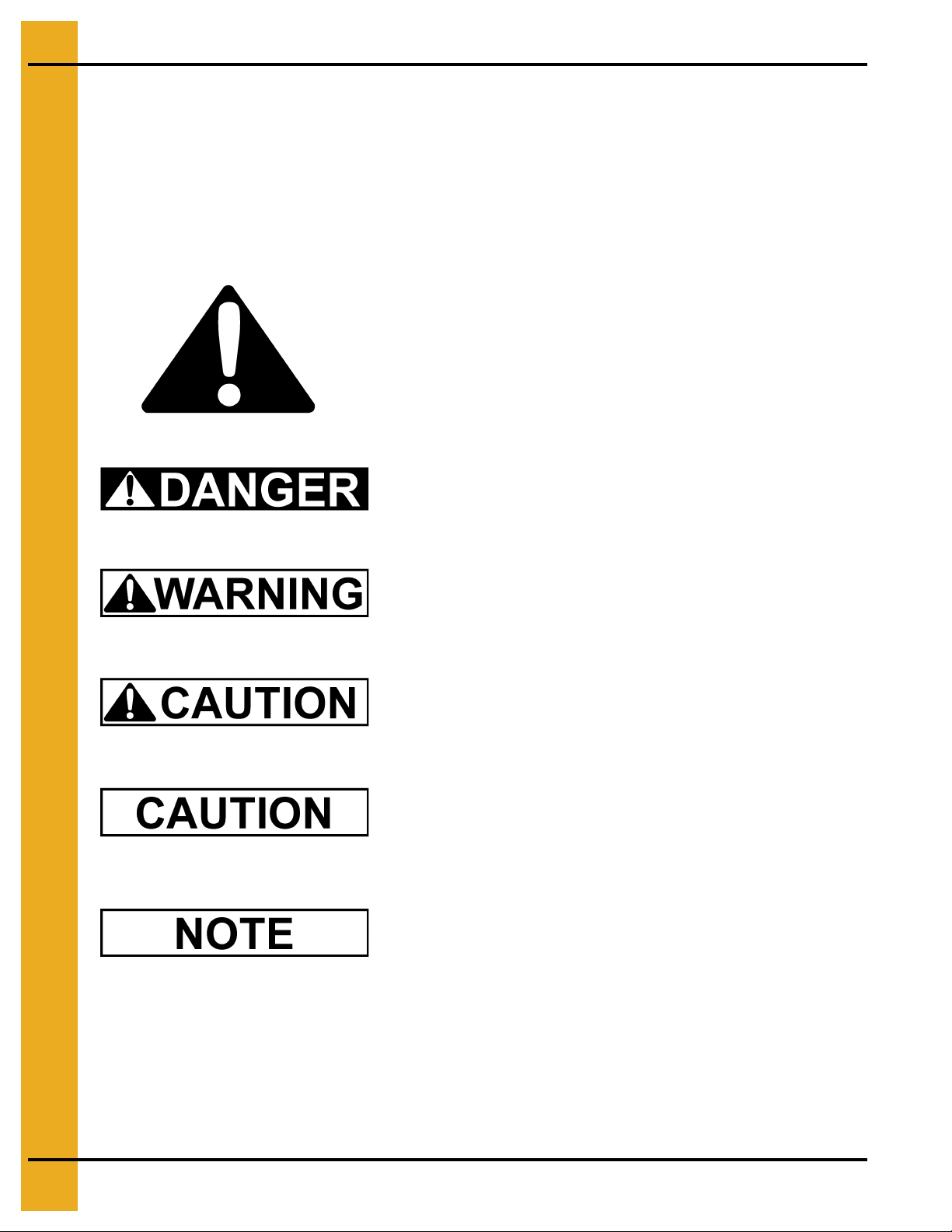
This is the safety alert symbol. It is used to alert you to
potential personal injury hazards. Obey all safety
messages that follow this symbol to avoid possible
injury or death.
WARNING indicates a potentially hazardous situation
which, if not avoided, could result in death or serious injury.
CAUTION indicates a potentially hazardous situation which,
if not avoided, may result in minor or moderate injury.
CAUTION used without the safety alert symbol indicates a
potentially hazardous situation which, if not avoided, may
result in property damage.
NOTE indicates information about the equipment that you
should pay special attention.
DANGER indicates an imminently hazardous situation
which, if not avoided, will result in death or serious injury.
Safety Guidelines
This manual contains information that is important for you, the owner/operator, to know and understand.
This information relates to protecting personal safety and preventing equipment problems. It is the
responsibility of the owner/operator to inform anyone operating or working in the area of this equipment
of these safety guidelines. To help you recognize this information, we use the symbols that are defined
below. Please read the manual and pay attention to these sections. Failure to read this manual and its
safety instructions is a misuse of the equipment and may lead to serious injury or death.
4 PNEG-1112 Sidewall Bin Stair Assembly
Page 5
1. Safety
This product has sharp edges, which may cause serious injury. To avoid injury, handle
sharp edges with caution and always use proper protective clothing and equipment.
General Safety Statement
Our foremost concern is your safety and the safety of others associated with grain handling equipment.
This manual is to help you understand safe operating procedures and some problems which may be
encountered by the operator and other personnel.
As owner and/or operator, you are responsible to know what requirements, hazards and precautions
exist and inform all personnel associated with the equipment or in the area. Safety precautions may be
required from the personnel. Avoid any alterations to the equipment, which may produce a very
dangerous situation, where SERIOUS INJURY or DEATH may occur.
You should consider the location of the bin site relative to power line locations or electrical tra nsmission
equipment. Contact your local power company to review your installation plan or for information
concerning required equipment clearance. Clearance of portable equipment that may be taken to the bin
site should also be reviewed and considered. Any electrical control equipment in contact with the bin
should be properly grounded and installed in accordance with National Electric Code provisions and
other local or national codes.
This product is intended for the use of grain storage only. Any other use is a misuse of the product.
Sidewall bundles or sheets must be stored in a safe manner. The safest method of storing sidewall
bundles is laying horizontally with the arch of the sheet upward, like a dome. Sidewall sheets stored o n
edge must be secured so that they cannot fall over and cause injury. Use care when handling and
moving sidewall bundles.
Personnel operating or working around equipment should read this manual. This manual must be
delivered with equipment to its owner. Failure to read this manual and its safety instructions is a misuse
of the equipment.
PNEG-1112 Sidewall Bin Stair Assembly 5
Page 6
1. Safety
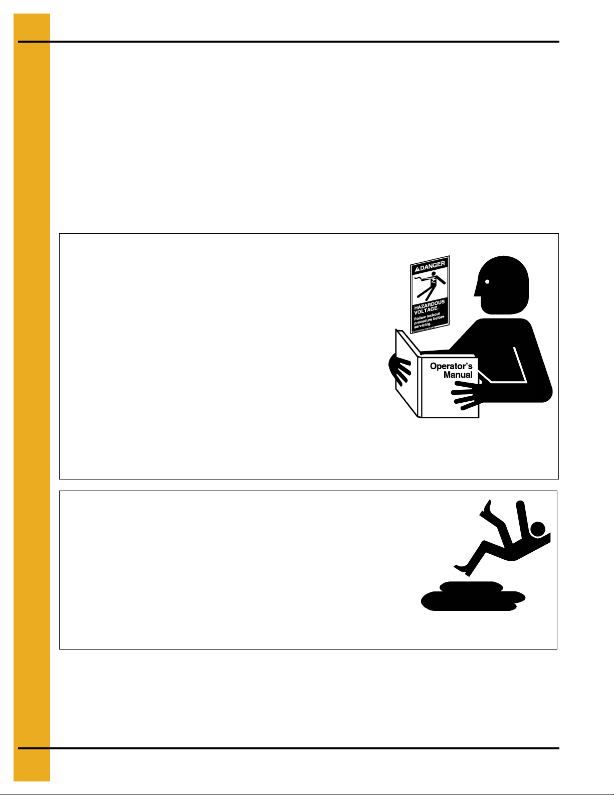
Follow Safety Instructions
Carefully read all safety messages in this manual and
safety signs on your machine. Keep signs in good
condition. Replace missing or damaged safety signs. Be
sure new equipment components and repair parts include
the current safety signs. Replacement safety signs are
available from the manufacturer.
Learn how to operate the machine and how to use controls
properly. Do not let anyone operate without instruction.
Keep your machinery in proper working condition.
Unauthorized modifications to the machine may impair
the function and/or safety and affect machine life.
If you do not understand any part of this manual or need
assistance, contact your dealer.
Read and Understand Manual
Practice Safe Maintenance
Understand service procedures before doing work. Keep area
clean and dry.
Never lubricate, service, or adjust machine while it is in operation.
Keep hands, feet and clothing away from rotating parts.
Keep all parts in good condition and properly installed. Fix
damage immediately . Replace worn or broken p arts. Remove any
built up grease oil and debris.
Maintain Equipment
and Work Area
Safety Instructions
Our foremost concern is your safety and the safety of others associated with this equipment. We want
to keep you as a customer. This manual is to help you understand safe op erating procedures and some
problems which may be encountered by the operator and other personnel.
As owner and/or operator, it is your responsibility to know what requirements, hazards and precautions
exist, and to inform all personnel associated with the equipment or in the area. Safety precautions may
be required from the personnel. Avoid any alterations to the equipment. Such alterations may produce
a very dangerous situation where SERIOUS INJURY or DEATH may occur.
This equipment shall be installed in accordance with the current installation codes and applicable
regulations which should be carefully followed in all cases. Authorities having jurisdiction should be
consulted before installations are made.
6 PNEG-1112 Sidewall Bin Stair Assembly
Page 7
1. Safety
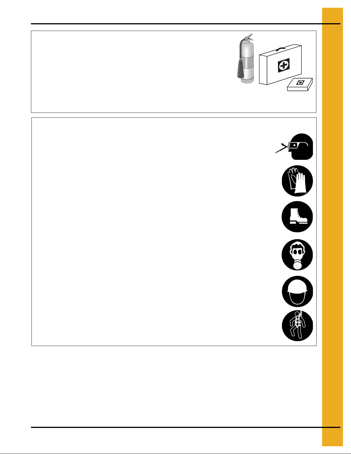
Prepare for Emergencies
Be prepared if fire starts.
Keep a first aid kit and fire extinguisher handy.
Keep emergency numbers for doctors, ambulance service,
hospital and fire department near your telephone.
Keep Emergency Equipment
Quickly Accessible
Wear Protective Clothing
Wear close fitting clothing and safety equipment appropriate
to the job.
Remove all jewelry.
Long hair should be tied up and back.
Safety glasses should be worn at all times to protect eyes
from debris.
Wear gloves to protect your hands from sharp edges on
plastic or steel parts.
Wear steel toe boots to help protect your feet from falling
debris. Tuck in any loose or dangling shoe strings.
A respirator may be needed to prevent breathing potentially
toxic fumes and dust.
Wear hard hat to help protect your head.
Wear appropriate fall protection equipment when working at
elevations greater than six feet (6').
Eye Protection
Gloves
Steel Toe Boots
Respirator
Hard Hat
Fall Protection
PNEG-1112 Sidewall Bin Stair Assembly 7
Page 8
2. Installation
Read and follow these directions carefully before an attempt is made at
installation. The GSI Group is not responsible for damage or accidents ca used by
improper installation or installation procedures. Our stairs are designed to
support the weight of one (1) person, and the weight that they can carry.
NOTE: The sidewall bin stair assembly can be installed ascending or descending, clockwise or
counterclockwise, when looking at a top down view of the bin. Also, they can be installed while
the bin is being assembled/erected, or after the bin is installed. The following assembly
instructions will show a descending clockwise installation after the bin has been installed.
NOTE: Care needs to be taken to ensure that nothing will obstruct the construction path of the stairs,
such as doors, conduit, heaters, fans, unloading equipment, etc.
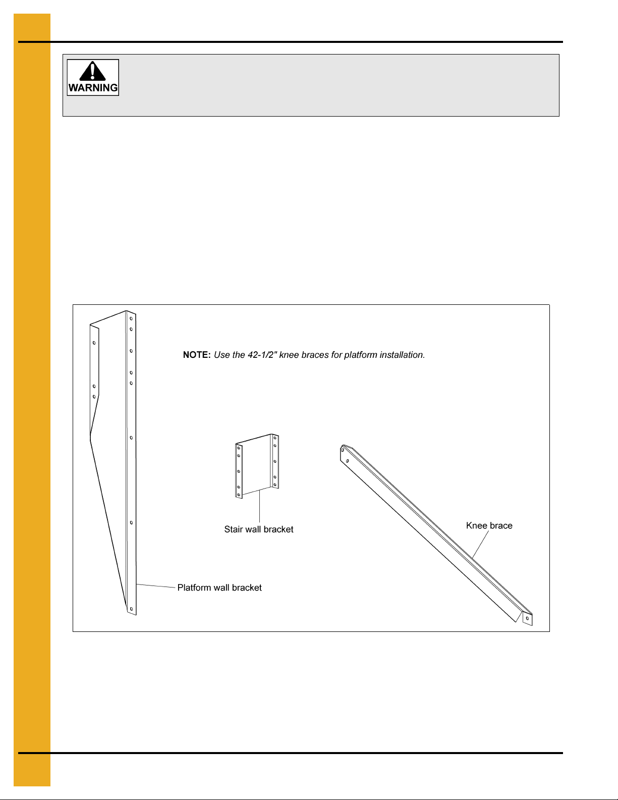
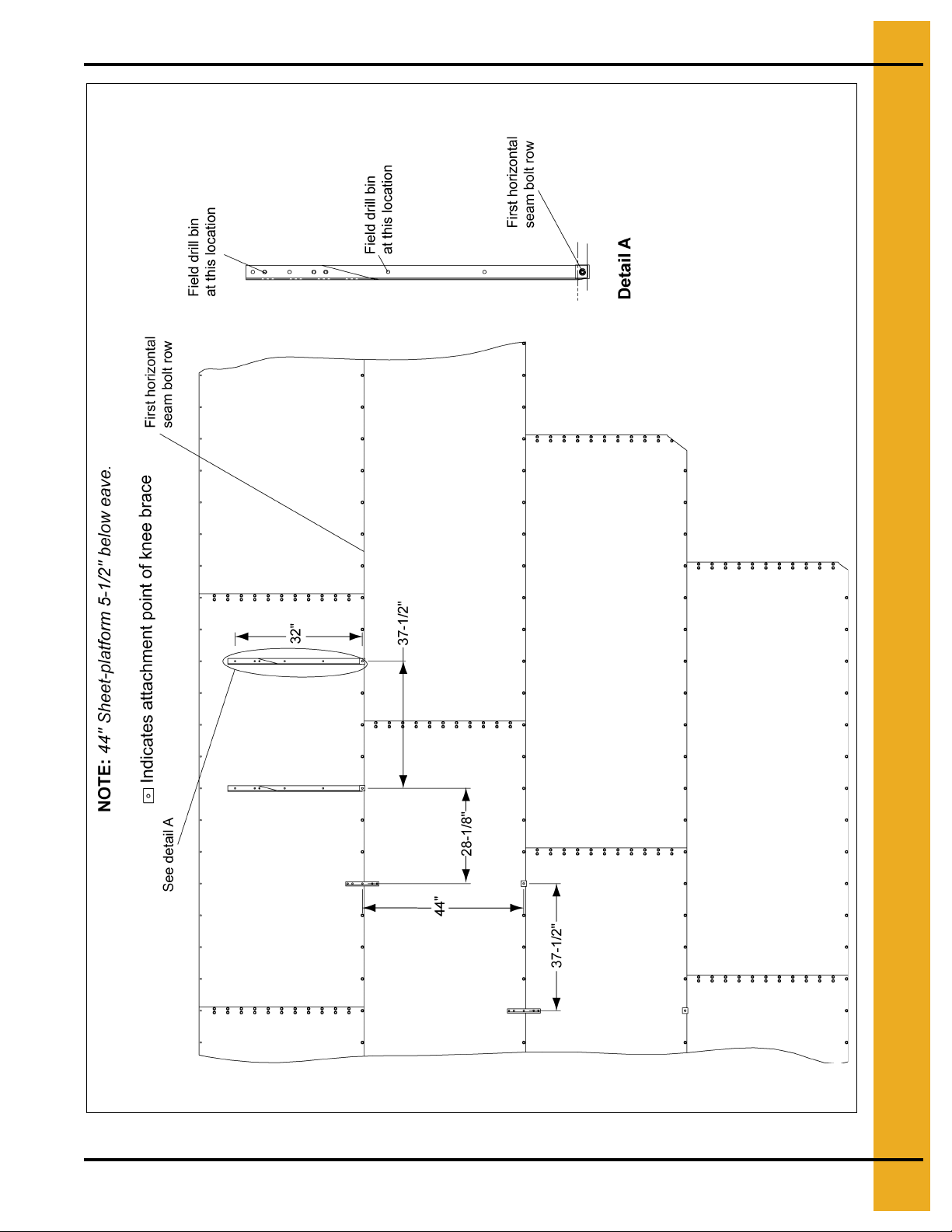
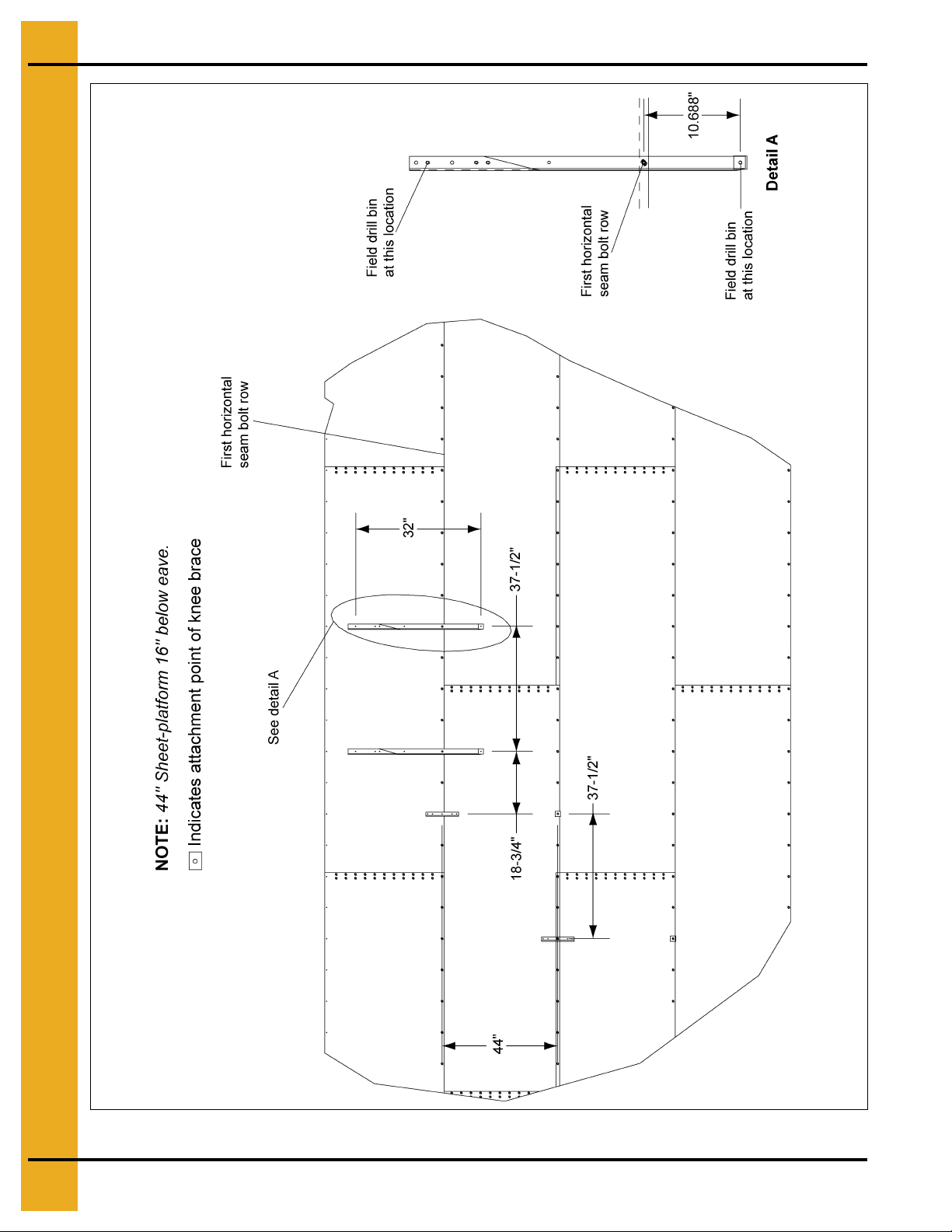
NOTE: All platforms are 39'' long, and extend 26'' from the bin wall.
Platform Wall Brackets, Stair Wall Brackets and Knee Braces
Determining and Marking Layout
Figure 2A
1. The attachment locations of the platform wall brackets to the first horizontal seam bolt row are
determined by the sheet size of the bin, and the distance below the eave, the platform will
be installed.
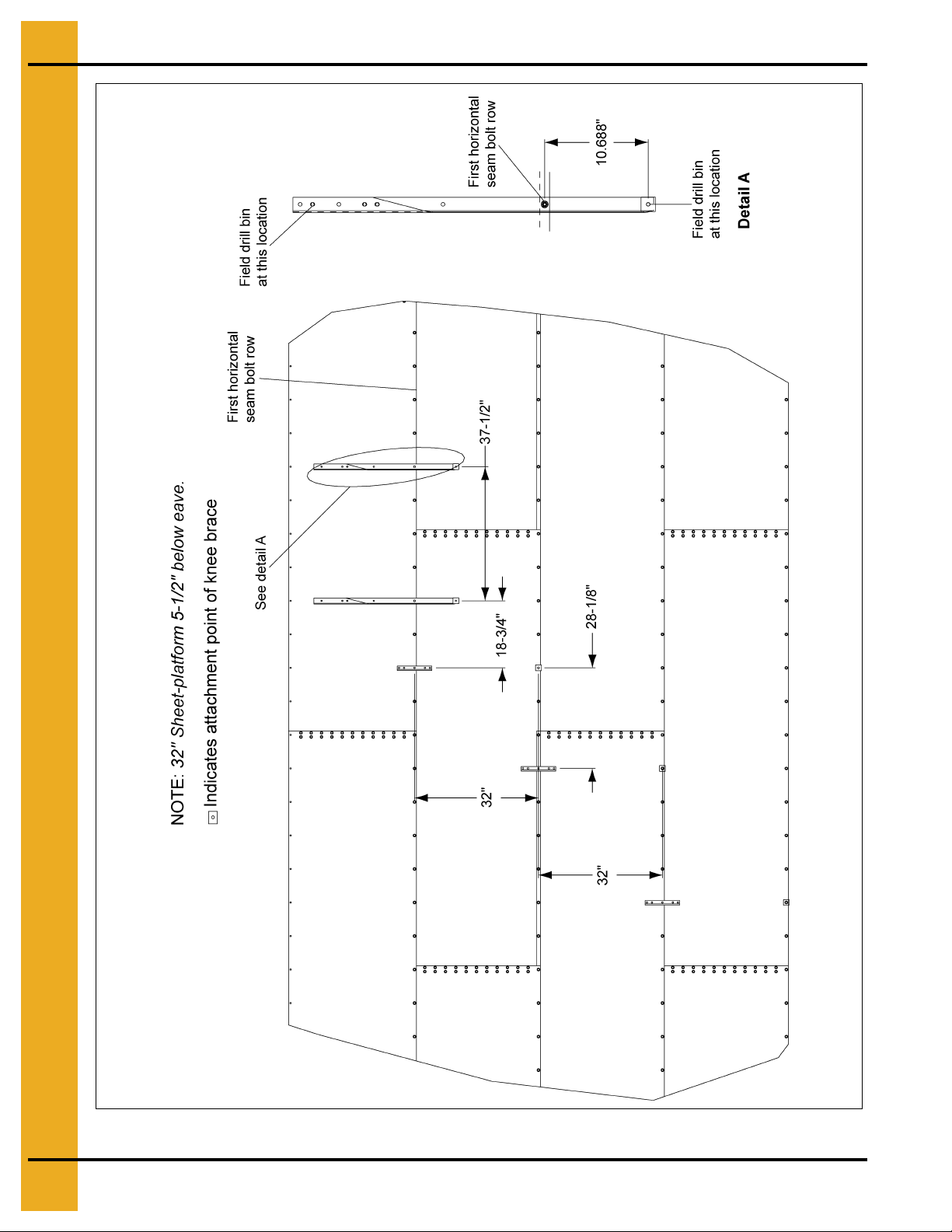
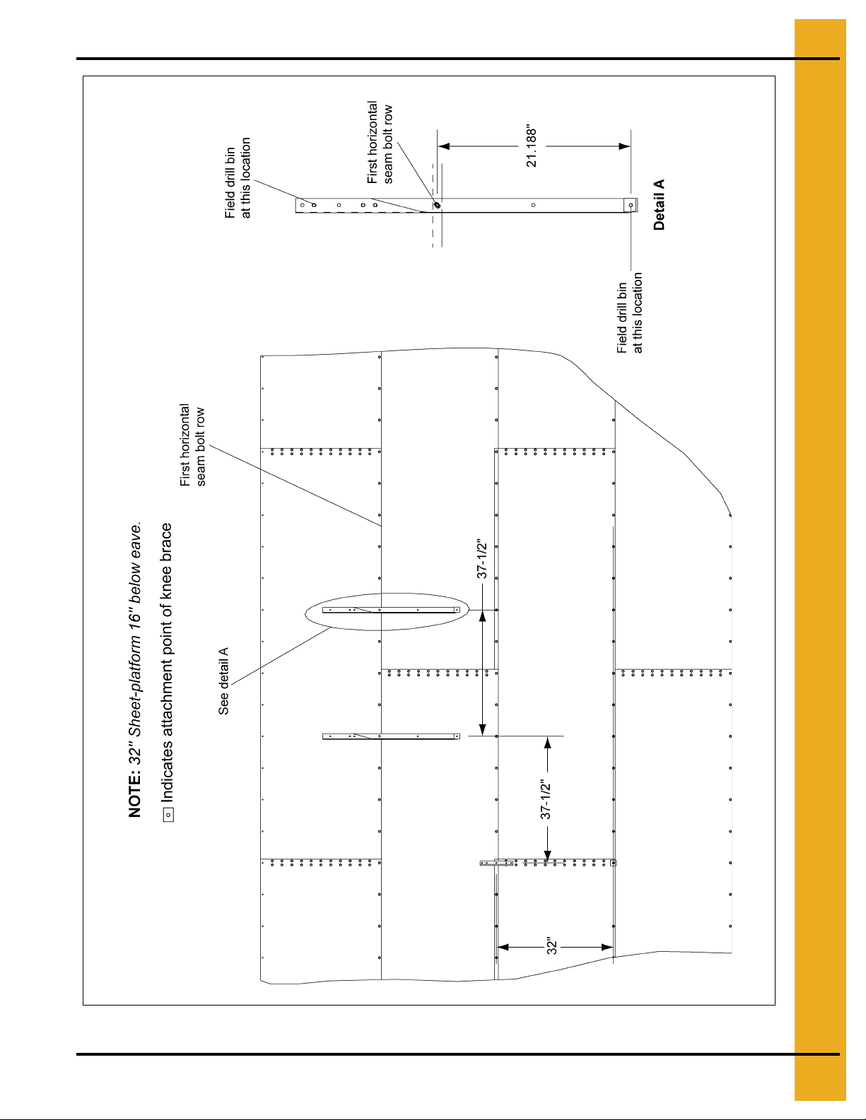
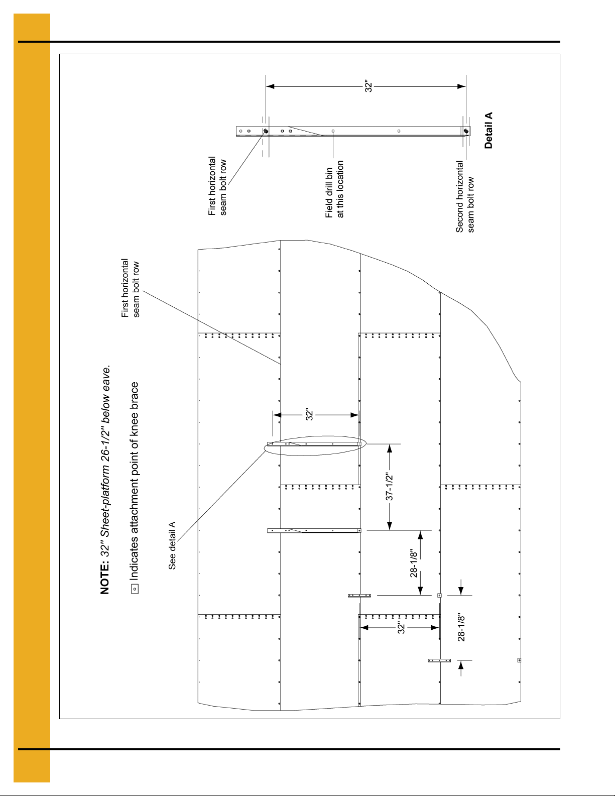
2. For 32'' and 44'' bin sheet size, the platform can be installed at a distance of 5-1/2'', 16'', or
26-1/2'' below the eave.
8 PNEG-1112 Sidewall Bin Stair Assembly
Page 9

2. Installation
3. Consult Figure 2B on Page 10 through Figure 2G on Page 15 for the layout of the attachment
points, and where you will have to field drill.
4. Line up the correct hole in the platform wall bracket with the first horizontal seam bolt row. The
correct hole is indicated in the detail view of the corresponding layout figure. Knee braces should
be installed at the same time as the platform wall brackets.
5. Mark the location of the holes to be field drilled for the platform wall brackets, stair wall brackets
and knee braces, as shown by the corresponding layout figure.
NOTE: All stair wall brackets should line up with a hole in the horizontal seam bolt rows, except for a
platform being installed 26-1/2'' below the eave on a 44'' bin sheet. Using the center hole on the
stair wall bracket, place it approximately two (2) bolts over and one (1) hole down from the
platform wall bracket attachment point to the first horizontal seam bolt row.
Drilling and Installation
1. Using the marked holes from the previous Steps, field drill the mounting locations as indicated in
the corresponding layout figure. Use an 11/32'' steel drill bit to make the holes.
2. Mount the platform wall brackets, stair wall brackets, and the knee braces with the provided
5/16'' x 1-1/4'' bin bolts and serrated flange nuts. The highest two (2) knee braces need to be the
42-1/2'' knee braces, instead of 34-3/4'' knee braces that may be part of the package.
3. At the bottom of the bin, the final wall bracket and knee brace will be installed with the final
stair section.
4. One (1) bolt spacing is the distance between the bolts on the horizontal seams, which is
equal to 9-3/8".
5. For 32" bin sheets: Each stair wall bracket after the first bracket will be lo cated three (3) bolt spaces
over (28-1/2") and one (1) horizontal seam down.
6. For 44" bin sheets: Each stair wall bracket after the first bracket (second bracket for 26-1/2" below
eave) will be located four (4) bolt spaces over (28-1/2") and one (1) horizontal seam down.
PNEG-1112 Sidewall Bin Stair Assembly 9
Page 10
2. Installation
Figure 2B
10 PNEG-1112 Sidewall Bin Stair Assembly
Page 11
2. Installation
Figure 2C
PNEG-1112 Sidewall Bin Stair Assembly 11
Page 12
2. Installation
Figure 2D
12 PNEG-1112 Sidewall Bin Stair Assembly
Page 13
2. Installation
Figure 2E
PNEG-1112 Sidewall Bin Stair Assembly 13
Page 14
2. Installation
Figure 2F
14 PNEG-1112 Sidewall Bin Stair Assembly
Page 15

2. Installation
Figure 2G
PNEG-1112 Sidewall Bin Stair Assembly 15
Page 16
2. Installation
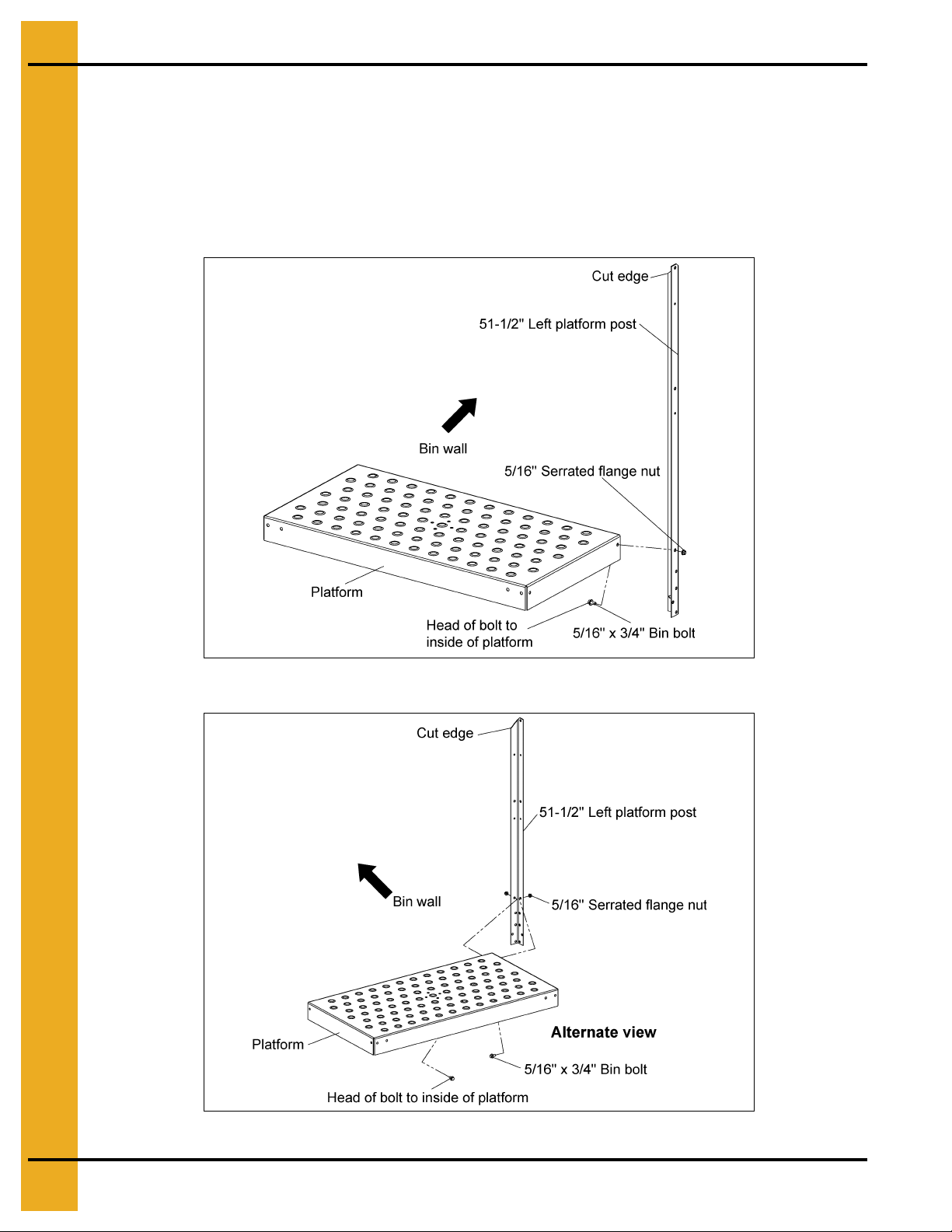
Platform Assembly and Installation
Assembling the Platform at Ground Level
1. Attach the 51-1/2'' left platform post to the platform using two (2) 5/16'' x 3/4 '' bin bolts and serrated
flange nuts. The head of the bin bolts should be on the inside of the platform. The cut edge of the
platform post should be located on the side of where the platform will attach to the platform wall
bracket. See Figure 2H and for an alternate view, see Figure 2I.
Figure 2H
Figure 2I
16 PNEG-1112 Sidewall Bin Stair Assembly
Page 17

2. Installation
2. Attach the corner platform post to the closest corner (opposite the platform wall bracket side of the
platform), using two (2) 5/16'' x 3/4'' bin bolts and serrated flange nuts. The head of the bin bolts
should be on the inside of the platform.
Figure 2J
3. Next, attach the 51-1/2" right platform post in between the platform and the outside siderail
extension using three (3) 5/16" x 3/4'' bin bolts and serrated flange nuts. The cut edge of the
platform post should be located so that it is perpendicular to where the bin wall will be. The outside
siderail extension has three (3) slots at its base which differs from the inside siderail extension
that has two (2) slots. The head of the bin bolts should be on the inside of the platform.
Figure 2K
PNEG-1112 Sidewall Bin Stair Assembly 17
Page 18

2. Installation
Figure 2L
4. Install one (1) 5/16'' x 3/4'' bin bolt and serrated flange nut to join the outsid e siderail extension and
the 51-1/2'' right platform post.
Figure 2M
18 PNEG-1112 Sidewall Bin Stair Assembly
Page 19

2. Installation
5. Attach the 9-1/2" sidewall post in between the platform and the inside siderail extension on the final
corner of the platform using three (3) 5/16'' x 3/4'' bin bolts and serrated flange nuts. The post
should point down from the top of the platform. The head of the bin bolts should be on the inside of
the platform.
Figure 2N
6. Bolt the two (2) 20'' sidewall stair handrails to the outside of the 51-1/2'' left platform post and the
outside of the corner post using four (4) 5/16'' x 1-1/2'' carriage bolts and serrated flange nuts. Make
sure that the handrails are fully seated on the posts.
Figure 2O
PNEG-1112 Sidewall Bin Stair Assembly 19
Page 20

2. Installation
7. Bolt the two (2) 39'' sidewall stair handrails to the outside of the 51-1/2'' right platform post and the
outside of the corner post using four (4) 5/16'' x 1-1/2'' carriage bolts and serrated flange nuts. Make
sure that the handrails are fully seated on the posts.
Figure 2P
Attach the Platform Assembly to the Platform Wall Brackets and Knee Braces
1. Loosely attach the 51-1/2'' left platform post to the platform wall bracket using two (2) 5/16'' x 3/4''
bin bolts and serrated flange nuts, in the bottom and third from the bottom holes of the post, and
the top two (2) holes in the platform wall bracket. (See Figure 2Q on Page 21.)
2. Loosely attach the inside siderail extension and the 9-1/2'' sidewall post to the other platform wall
bracket using one (1) 5/16'' x 3/4'' bin bolt and serrated flange nut, in the top hole of the platform
wall bracket, and the matching hole in the inside siderail extension and the 9-1/2'' sidewall post.
3. Loosely attach the corner platform post to the right 42-1/2'' knee brace using two (2) 5/16'' x 3/4''
bin bolts and serrated flange nuts. The head of one (1) bin bolt should be on the corner platform
post and the head of the other bin bolt should be on the knee brace.
4. And finally, loosely attach the 51-1/2'' right platform post to the left 42-1/2'' knee brace using
two (2) 5/16'' x 3/4'' bin bolts and serrated flange nuts. The head of the one (1) bin b olt should be on
the 51-1/2'' right platform post and the head of the other bin bolt should be on the knee brace.
5. Tighten all bin bolts and serrated flange nuts, adjusting as necessary so the posts are as vertical
as possible.
20 PNEG-1112 Sidewall Bin Stair Assembly
Page 21

2. Installation
Figure 2Q
PNEG-1112 Sidewall Bin Stair Assembly 21
Page 22

2. Installation
Assemble Steps to Siderails
Stair Section Assembly
The 2 step, 3 step, and 4 step stair sections are all assembled in the same fashion. The following
instructions are for assembling a 3 step stair section.
The inside stair siderail is different from the outside stair siderail in the same way as the inside and
outside siderail extensions. The outside stair siderail has three (3) slots at its ends, while the inside stair
siderail has two (2) slots. The painted edge should be at the top of the stair section.
Figure 2R
Assemble the steps.
1. To the inside stair siderail, loosely attach a 9'' x 20'' step using two (2) 5/16'' x 3/4'' bin bolts and
serrated flange nuts. The heads of the bin bolts should on the outside of the inside stair siderail and
not to the inside of the step.
Figure 2S
22 PNEG-1112 Sidewall Bin Stair Assembly
Page 23

2. Repeat Step 1 on Page 22 for the quantity of steps in the package.
2. Installation
Figure 2T
3. Loosely attach the outside stair siderail to the 9'' x 20'' steps using two (2) 5/16'' x 3/4'' bin bolts
and serrated flange nuts for each step. The heads of the bin bolts should be on the outside of the
outside stair siderail and not to the inside of the step.
Figure 2U
NOTE: 4 Step sections have slots for the top and bottom step attachment to the outside stair rail.
The step should be fitted in the slot to a position that allows the rail to curve around the bin.
PNEG-1112 Sidewall Bin Stair Assembly 23
Page 24

2. Installation
4. Loosely bolt the handrail baluster to the outside stair siderail using one (1) 5/16" x 3/4" bin bolt and
serrated flange nut. The bin bolt and serrated flange nut should be preliminarily installed to the
inside end of the rear slot for bins greater than 30' in diameter, and to the hole outside of the slots
for bins less than or equal to 30' in diameter.
Figure 2V
Figure 2W
5. The loosely assembled stair section is now ready to be installed on the bin. After the stairs are
put into place and adjusted appropriately, the bin bolts and serrated flange nuts can be tightened.
24 PNEG-1112 Sidewall Bin Stair Assembly
Page 25

2. Installation
Installation of the First Stair Section to the Platform Assembly
Figure 2X
PNEG-1112 Sidewall Bin Stair Assembly 25
Page 26

2. Installation
Inside Stair Siderail Attachment
Lift the assembled stair section close to the installed platform assembly.
1. Sandwich the inside stair siderail from the assembled stair section between the inside of the inside
siderail extension, and the outside of the 9-1/2'' sidewall post.
Figure 2Y
Figure 2Z
26 PNEG-1112 Sidewall Bin Stair Assembly
Page 27

2. Installation
2. Insert two (2) 5/16'' x 3/4" bin bolts into the two (2) mating slots on the inside of the inside stair
siderail, and one (1) 5/16'' x 3/4'' bin bolt to the bottom hole on the 9-1/2'' sidewall post. Loo sely join
the bin bolts to two (2) serrated flange nuts on the outside of the inside siderail extension, and
one (1) serrated flange nut on the inside of the platform wall bracket. These bin bolts and serrated
flange nuts will be adjusted and tightened after the assembled stair section is in place.
Figure 2AA
Outside Stair Siderail Attachment
1. Place the outside stair siderail to the outside of the outside siderail extension.
Figure 2AB
2. For installation on bins greater than 30' in diameter, align the first and second slot on the outside
stair siderail to the second and third slot on the outside siderail extension. For bins with a diameter
of 30' or less, align the first single hole and the third slot in the outside stair siderail with the first slot
and last single hole in the outside siderail extension.
PNEG-1112 Sidewall Bin Stair Assembly 27
Page 28

2. Installation
3. Insert two (2) 5/16'' x 3/4'' bin bolts into the two (2) mating slots on the inside of the outside siderail
extension. Loosely join the bin bolts to two (2) serrated flange nuts on the outside of the outside
stair siderail. These bin bolts and serrated flange nuts will be adjusted and tightened after the
assembled stair section is in place.
Figure 2AC
Inside Stair Siderail Attachment to Wall Bracket
1. Bring the bottom end of the inside stair siderail close to the nearest installed wall bracket by curving
the inside stair siderail.
2. Loosely attach the inside stair siderail to the wall bracket with one (1) 5/16'' x 3/4'' bin bolt and
serrated flange nut. Use the top hole in the wall bracket and the upper slot at the bottom of the
inside stair siderail.
Figure 2AD
28 PNEG-1112 Sidewall Bin Stair Assembly
Page 29

2. Installation
Attach Handrail Baluster to Knee Brace
1. Bring the bottom of the handrail baluster to the top of the nearest installed knee brace.
2. Loosely attach the handrail baluster to the knee brace using two (2) 5/16'' x 3/4'' bin bolts and
serrated flange nuts. The head of the one (1) bin bolt should be on the handrail baluster and the
head of the other bin bolt should be on the knee brace.
3. Attach handrail baluster to the outside stair siderail using a 5/16" x 3/4" bin bolt and serrated
flange nut.
Figure 2AE
Final Adjustments of First S tair Section
1. Adjust the steps to fit the curve of the bin. Use a level to ensure the steps are level in all directions.
2. Tighten all bin bolts and serrated flange nuts that assemble the stair section.
3. Tighten the bin bolts and serrated flange nuts that attach the stair section to the platform, wall
brackets, and knee braces.
PNEG-1112 Sidewall Bin Stair Assembly 29
Page 30

2. Installation
Attachment of Consecutive Stair Sections
NOTE: Depending on the size of the bin, and the bent edges of the stair siderails, the inside stair
siderails can overlap the next inside stair siderail in both directions. (Figure 2AG and Figure 2AH
on Page 31.) The outside stair siderails have the same possibilities. It is important to assemble
the stair sections consistently, therefore keep the overlap the same for each consecutive section.
Figure 2AF
30 PNEG-1112 Sidewall Bin Stair Assembly
Page 31

2. Installation
Figure 2AG
Figure 2AH
PNEG-1112 Sidewall Bin Stair Assembly 31
Page 32

2. Installation
Attaching the Inside Siderail
Bring the next assembled stair section to the previously installed stair section.
1. Place the outside surface of the inside stair siderail to the inside of the already installed inside
stair siderail.
2. Using Figure 2AI and Figure 2AJ, loosely bolt the two (2) inside stair siderails together with
two (2) 5/16'' x 3/4'' bin bolts and serrated flange nuts, and the inside stair siderail to the wall bracket
with one (1) 5/16'' x 3/4'' bin bolt and serrated flange nut. Note the four (4) total attachment points
on the figures.
Figure 2AI
Figure 2AJ
32 PNEG-1112 Sidewall Bin Stair Assembly
Page 33

2. Installation
Attaching the Outside Siderail
1. Place the inside surface of the outside stair siderail to the outside surface of the already installed
outside stair siderail.
2. Using Figure 2AK and Figure 2AM, loosely bolt the two (2) outside stair siderails together with
two (2) 5/16'' x 3/4'' bin bolts and serrated flange nuts, and the outside stair siderail to the handrail
baluster with one (1) 5/16'' x 3/4'' bin bolt and serrated flange nut. Note the four (4) total attachment
points on the figures.
Figure 2AK
3. Figure 2AL shows a detail of the overlapping outside rails of a 4 step section. The figure is to be
used for 42'-60' diameter bins. The chart associated with the figure gives an approximate relation
between the two (2) outside rails. This chart is a guideline only. Overlap distances may vary in order
to keep the stairs level. Use a level to ensure the stairs are level in all directions.
Figure 2AL
PNEG-1112 Sidewall Bin Stair Assembly 33
Page 34

2. Installation
Figure 2AM
4. Figure 2AN shows a detail of the overlapping outside rails of a 4 step section. The figure is to be
used for 21' to 36' diameter bins. The chart associated with the figure gives an approximate relation
between the two (2) outside rails. This chart is a guideline only. Overlap distances may vary in order
to keep the stairs level. Use a level to ensure the stairs are level in all directions.
Figure 2AN
Inside Stair Siderail
Refer to instruction
Refer to instructions
34 PNEG-1112 Sidewall Bin Stair Assembly
on Page 28
on Page 30
“Inside stair siderail attachment to wall bracket” for subsequent stair section.
“Attachment of consecutive stair sections” for subsequent stair sections.
Page 35

2. Installation
Installation of Bottom Brace and Bracket
Bottom Brace Bracket
1. For the last stair section, attach the wall bracket to the bin wall, using the bottom hole in the wall
bracket, with one (1) 5/16'' x 1-1/4'' bin bolt and serrated flange nut.
2. The bottom brace bracket installs to the outside stair siderail and th e handrail baluster on one end,
and the wall bracket and inside stair siderail on the other end.
3. Attach the inside stair siderail to the wall bracket and the bottom brace bracket using two (2)
5/16'' x 3/4'' bin bolts and serrated flange nuts.
Figure 2AO
PNEG-1112 Sidewall Bin Stair Assembly 35
Page 36

2. Installation
4. Attach the bottom brace bracket to the outside stair siderail and the handrail baluster using
two (2) 5/16'' x 3/4'' bin bolts and serrated flange nuts.
Figure 2AP
Field cut the handrail baluster below the bottom brace bracket so that it does not interfere with the bin
pad or ground.
Figure 2AQ
36 PNEG-1112 Sidewall Bin Stair Assembly
Page 37

2. Installation
Lower Support of the Stairs
1. In some cases the foundation is not as wide as the outside of the stair section. In this case, the
outside of the stair section needs to be supported to keep the stairs level. This should be done by
field fabrication of an angle back to the concrete foundation or supporting the outside rail with
blocks or a concrete pad. Use a level to check the stairs in all directions and shim the outside rail
when necessary.
Bottom Knee Brace
1. Attach the final knee brace to the bottom brace bracket using one (1) 5/16'' x 3/4'' bin bolt and
serrated flange nut. For clarity, the outside stair siderail is hidden.
Figure 2AR
2. Bring the knee brace close to the bin wall, and mark the hole where it attaches. Field drill the hole
with an 11/32'' steel bit, and bolt the knee brace to the bin wall using one (1) 5/16'' x 1-1/4'' bin bolt
and serrated flange nut.
Figure 2AS
PNEG-1112 Sidewall Bin Stair Assembly 37
Page 38

2. Installation
Handrail Installation
After all the stair sections have been assembled and installed, the upper and lower handrails can be
installed. The handrails can be installed top down, or bottom up.
The handrails have a smaller diameter at their upper ends, and have a pre-drilled hole at the lower end
to aid installation.
NOTE: The lengths of handrails that are provided correspond to the differing stair section lengths.
Assemble the correct handrails to the appropriate stair sections.
Figure 2AT
Lower Handrail Installation
1. Using the appropriate length of handrail, use one (1) 1/4'' x 1'' self drilling screw to attach the lower
end of the handrail to the inside surface of the lowest handrail baluster. The head of the screw
should be on the outside surface of the handrail baluster.
Figure 2AU
38 PNEG-1112 Sidewall Bin Stair Assembly
Page 39

2. Installation
NOTE: The handrails are not shipped pre-curved. As the lower and upper handrails are installed, they
must be curved/bent to match the curve of the bin, and in order to attach to the handrail balusters
at the appropriate attachment points.
2. With the next appropriate length handrail, overlap the to-be-installed handrail to the previously
installed handrail. The two (2) handrails should overlap by at least 2''.
Figure 2AV
3. Where the installed handrail(s) meet up with the next higher handrail baluster, use one (1)
1/4'' x 1'' self drilling screw to attach the handrail to the inside surface of the handrail baluster.
The head of the screw should be on the outside surface of the handrail baluster.
Figure 2AW
4. Repeat Previous Steps until the handrail reaches the 51-1/2'' right platform post.
PNEG-1112 Sidewall Bin Stair Assembly 39
Page 40

2. Installation
5. Where the assembled lower handrail meets the 51-1/2'' right platform post, use one (1)
1/4'' x 1'' self drilling screw to attach it to the outside surface of the post. The head of the screw
should be on the inside surface of the 51-1/2'' right platform post.
Figure 2AX
Upper Handrail Installation
1. Using the matching length of handrail to the installed lower handrail, use one (1) 1/4'' x 1''
self drilling screw to attach the lower end of the handrail to the outside surface of the lowest
handrail baluster. The head of the screw should be on the inside surface of the handrail baluster.
Figure 2AY
40 PNEG-1112 Sidewall Bin Stair Assembly
Page 41

2. Installation
NOTE: In the same way that the lower handrails had to be curved/bent to match t he curve of the bin, the
upper handrails have to be adjusted to match.
2. With the next appropriate length handrail, overlap the to-be-installed handrail to the previously
installed handrail. The two (2) handrails should overlap by at least 2''.
3. Where the installed handrail(s) meet up with the next higher handrail baluster, use one (1)
1/4'' x 1'' self drilling screw to attach the handrail to the outside surface of the handrail baluster. The
head of the screw should be on the inside surface of the handrail baluster.
Figure 2AZ
4. Repeat Previous Steps until the handrail reaches the 51-1/2'' right platform post.
5. Where the assembled lower handrail meets the 51-1/2'' right platform post, use one (1) 1/4'' x 1''
self drilling screw to attach it to the outside surface of the post. The head of the screw should be
on the inside surface of the 51-1/2'' right platform post.
Figure 2BA
PNEG-1112 Sidewall Bin Stair Assembly 41
Page 42

3. Parts List
Optional Platform Packages
42 PNEG-1112 Sidewall Bin Stair Assembly
Page 43

Package Charts for the Top Two Rings
32'' Tall Bin Sidewall Sheet 44'' Tall Bin Sidewall Sheet
STR1003 Platform STR1003 Platform
Platform 5-1/2"
Below Eave
Platform 16"
Below Eave
Platform 26-1/2"
Below Eave
Intermediate
Platform
STR1000 21'' Section STR1001 32'' Section
STR1001 32'' Section STR1002 44'' Section
STR1003 Platform STR1003 Platform
STR1002 44'' Section STR1000 21'' Section
STR1002 44'' Section
STR1003 Platform STR1003 Platform
STR1009 Booster Setup STR1009 Booster Setup
STR1001 32'' Section STR1000 21'' Section
STR1001 32'' Section
STR1005 Intermediate Platform STR1005 Intermediate Platform
STR1001 32'' Section STR1001 32'' Section
Listed in Order to be Placed on Bin from First to Last for Each Scenario
3. Parts List
Example: Eight (8) 32'' bin rings with a platform 16'' below eave uses one (1) STR1003 platform,
one (1) STR1002 stair section, and six (6) STR1001 stair sections.
Stair and Platform Packages (Hardware is included with each packages)
21'' Stair Section (STR1000)
Part # Description Qty
STR0008 Wall Bracket 6'' x 1'' x 9'' Channel 1
STR0012 Baluster Post 54'' 1
STR0013 Knee Brace 32'' Section 34-3/4'' 1
STR0010 Siderail Outside 21'' Section 38'' 1
STR0009 Siderail Inside 21'' Section 35'' 1
STR0011 Step 9'' x 20'' 2
STR0014 Handrail 21'' Section 34'' 2
32'' Stair Section (STR1001)
Part # Description Qty
STR0008 Wall Bracket 6'' x 1'' x 9'' Channel 1
STR0012 Baluster Post 54'' 1
STR0013 Knee Brace 32'' Section 34-3/4'' 1
STR0022 Siderail Outside 32'' Section 53'' 1
STR0023 Siderail Inside 32'' Section 50'' 1
STR0011 Step 9'' x 20'' 3
STR0043 Handrail 32'' Section 51'' 2
PNEG-1112 Sidewall Bin Stair Assembly 43
Page 44

3. Parts List
44'' Stair Section (STR1002)
Part # Description Qty
STR0008 Wall Bracket 6'' x 1'' x 9'' Channel 1
STR0012 Baluster Post 54'' 1
STR0046 Knee Brace 44'' Section 42-1/2'' 1
STR0024 Siderail Outside 44'' Section 70-1/4'' 1
STR0025 Siderail Inside 44'' Section 65'' 1
STR0011 Step 9'' x 20'' 4
STR0045 Handrail 44'' Section 67-1/2'' 2
Platform (STR1003)
Part # Description Qty
STR0046 Knee Brace 44'' Section 42-1/2'' 2
STR0054 Bottom Knee Brace Bracket 1
STR0049 Post 9-1/2'' 1
STR0050 Platform Post Right 51-1/2'' 1
STR0051 Platform Post Left 51-1/2'' 1
STR0052 Platform Corner Post Right 51-1/2'' 1
STR0053 Platform Wall Bracket 37'' 2
STR0027 Outside Siderail Extension 1
STR0026 Inside Siderail Extension 1
STR0048 Platform 1
STR0055 Platform Handrail 20'' 2
STR0056 Platform Side Handrail 39'' 2
Intermediate Platform (STR1005)
Part # Description Qty
STR0008 Wall Bracket 6'' x 1'' x 9'' Channel 1
STR0046 Knee Brace 44'' Section 42-1/2'' 2
STR0049 Post 9-1/2'' 2
STR0050 Platform Post Right 51-1/2'' 1
STR0051 Platform Post Left 51-1/2'' 1
STR0027 Outside Siderail Extension 2
STR0026 Inside Siderail Extension 2
STR0056 Platform Side Handrail 39'' 2
44 PNEG-1112 Sidewall Bin Stair Assembly
Page 45

Twin Platform (STR1006)
Part # Description Qty
STR0046 Knee Brace 44'' Section 42-1/2'' 2
STR0050 Platform Post Right 51-1/2'' 2
STR0051 Platform Post Left 51-1/2'' 2
STR0053 Platform Wall Bracket 37'' 2
STR0048 Platform 1
STR0055 Platform Handrail 20'' 4
Ladder Platform (STR1007)
Part # Description Qty
STR0046 Knee Brace 44'' Section 42-1/2'' 2
STR0049 Post 9-1/2'' 1
STR0050 Platform Post Right 51-1/2'' 1
3. Parts List
STR0051 Platform Post Left 51-1/2'' 1
STR0052 Platform Corner Post Right 51-1/2'' 1
STR0053 Platform Wall Bracket 37'' 2
STR0048 Platform 1
STR0055 Platform Handrail 20'' 2
STR0056 Platform Side Handrail 39'' 2
Booster Handrail (STR1009)
Part # Description Qty
STR0058 Booster Step 7'' x 20'' 1
STR0059 Right Booster Rail 1
STR0060 Left Booster Handrail 1
PNEG-1112 Sidewall Bin Stair Assembly 45
Page 46

3. Parts List
Sidewall Stair Platform Components (STR1003)
Sidewall Stair Platform Components (STR1003) Parts List
Ref # Part # Description
1 STR0048 Sidewall Stair Platform
2 STR0051 51-1/2'' Left Platform Post
3 S-275 5/16"-18 x 3/4'' HH Bin Zinc Grade 5 w/ Washer
4 S-3611 5/16"-18 Serrated Flange Nut Zinc Grade 2
5 STR0052 Corner Platform Post
6 STR0050 51-1/2'' Right Platform Post
7 STR0027 Outside Siderail Extension
8 STR0049 9-1/2" Sidewall Post
9 STR0026 Inside Siderail Extension
10 STR0055 20" Sidewall Stair Handrail
11 S-6996 5/16"-18 x 1-1/2" Carriage Bolt Zinc Grade 5
12 STR0056 39" Sidewall Stair Handrail
13 STR0053 Platform Wall Bracket
14 S-277 5/16"-18 x 1-1/4'' HH Bin Zinc Grade 5 w/ Washer
15 STR0046 1-1/2'' x 42-1/2'' Knee Brace
16 STR0054 Bottom Brace Bracket
17 S-7229 1/4'' x 1'' SDS Zinc
46 PNEG-1112 Sidewall Bin Stair Assembly
Page 47

Stair Section Components (STR1000)
3. Parts List
Stair Section Components (STR1000) Parts List
Ref # Part # Description
1 STR0009 10" x 35-1/2" Inside Stair Siderail
2 S-275 5/16"-18 x 3/4" HH Bin Zinc Grade 5 w/ Washer
3 S-3611 5/16"-18 Serrated Flange Nut Zinc Grade 2
4 STR0011 9" x 20" Step
5 STR0010 10" x 38" Outside Stair Siderail
6 STR0012 Handrail Baluster
7 STR0008 Stair Wall Bracket
8 S-277 5/16"-18 x 1-1/4" HH Bin Zinc Grade 5 w/ Washer
9 STR0013 1-1/2" x 34-3/4" Knee Brace
10 STR0014 1" I.D. x 39" Handrail
11 S-7229 1/4" x 1" SDS Zinc
PNEG-1112 Sidewall Bin Stair Assembly 47
Page 48

3. Parts List
Stair Section Components (STR1001)
Stair Section Components (STR1001) Parts List
Ref # Part # Description
1 STR0023 10" x 50" Inside Stair Siderail
2 S-275 5/16"-18 x 3/4" HH Bin Zinc Grade 5 w/ Washer
3 S-3611 5/16"-18 Serrated Flange Nut Zinc Grade 2
4 STR0011 9" x 20" Step
5 STR0022 10" x 53" Outside Stair Siderail
6 STR0012 Handrail Baluster
7 STR0008 Stair Wall Bracket
8 S-277 5/16"-18 x 1-1/4" HH Bin Zinc Grade 5 w/ Washer
9 STR0013 1-1/2" x 34-3/4" Knee Brace
10 STR0043 1" I.D. x 51" Handrail
11 S-7229 1/4" x 1" SDS Zinc
48 PNEG-1112 Sidewall Bin Stair Assembly
Page 49

Stair Section Components (STR1002)
3. Parts List
Stair Section Components (STR1002) Parts List
Ref # Part # Description
1 STR0025 10" x 65" Inside Stair Siderail
2 S-275 5/16"-18 x 3/4" HH Bin Zinc Grade 5 w/ Washer
3 S-3611 5/16"-18 Serrated Flange Nut Zinc Grade 2
4 STR0011 9" x 20" Step
5 STR0024 10" x 70-1/4" Outside Stair Siderail
6 STR0012 Handrail Baluster
7 STR0008 Stair Wall Bracket
8 S-277 5/16"-18 x 1-1/4" HH Bin Zinc Grade 5 w/ Washer
9 STR0046 1-1/2" x 42-1/2" Knee Brace
10 STR0045 1" I.D. x 68" Handrail
11 S-7229 1/4" x 1" SDS Zinc
PNEG-1112 Sidewall Bin Stair Assembly 49
Page 50

NOTES
50 PNEG-1112 Sidewall Bin Stair Assembly
Page 51

4. Warranty
9101239_1_CR_rev7.DOC (revised July 2009)
GSI Group, LLC Limited Warranty
The GSI Group, LLC (“GSI”) warrants products which it manufactures to be free of defects in materials and workmanship
under normal usage and conditions for a period of 12 months after sale to the original end-user or if a foreign sale,
14 months from arrival at port of discharge, whichever is earlier. The end-user’s sole remedy (and GSI’s only obligation)
is to repair or replace, at GSI’s option and expense, products that in GSI’s judgment, contain a material defect in materials
or workmanship. Expenses incurred by or on behalf of the end-user without prior written authorization from the GSI
Warranty Group shall be the sole responsibility of the end-user.
Warranty Extensions:
The Limited Warranty period is extended for the following products:
Product Warranty Period
Performer Series Direct Drive Fan Motor 3 Years
AP Fans and Flooring
Cumberland
Feeding/Watering
Systems
Grain Systems Grain Bin Structural Design 5 Years
Grain Systems
Farm Fans
Zimmerman
All Fiberglass Housings Lifetime
All Fiberglass Propellers Lifetime
Feeder System Pan Assemblies 5 Years **
Feed Tubes (1-3/4" and 2.00") 10 Years *
Centerless Augers 10 Years *
Watering Nipples 10 Years *
Portable and Tower Dryers 2 Years
Portable and Tower Dryer Frames and
Internal Infrastructure †
5 Years
* Warranty prorated from list price:
0 to 3 years - no cost to end-user
3 to 5 years - end-user pays 25%
5 to 7 years - end-user pays 50%
7 to 10 years - end-user pays 75%
** Warranty prorated from list price:
0 to 3 years - no cost to end-user
3 to 5 years - end-user pays 50%
† Motors, burner components
and moving parts not included.
Portable dryer screens included.
Tower dryer screens not included.
GSI further warrants that the portable and tower dryer frame and basket, excluding all auger and auger drive
components, shall be free from defects in materials for a period of time beginning on the twelfth (12
the date of purchase and continuing until the sixtieth (60
th
) month from the date of purchase (extended warranty period).
th
) month from
During the extended warranty period, GSI will replace the frame or basket components that prove to be defective
under normal conditions of use without charge, excluding the labor, transportation, and/or shipping costs incurred in
the performance of this extended warranty.
Conditions and Limitations:
THERE ARE NO WARRANTIES THAT EXTEND BEYOND THE LIMITED WARRANTY DESCRIPTION SET FORTH
ABOVE. SPECIFICALLY, GSI MAKES NO FURTHER WARRANTY OF ANY KIND, EXPRESS OR IMPLIED,
INCLUDING, WITHOUT LIMITATION, WARRANTIES OF MERCHANTABILITY OR FITNESS FOR A PARTICULAR
PURPOSE OR USE IN CONNECTION WITH: (I) PRODUCT MANUFACTURED OR SOLD BY GSI OR (II) ANY
ADVICE, INSTRUCTION, RECOMMENDATION OR SUGGESTION PROVIDED BY AN AGENT, REPRESENTATIVE
OR EMPLOYEE OF GSI REGARDING OR RELATED TO THE CONFIGURATION, INSTALLATION, LAYOUT,
SUITABILITY FOR A PARTICULAR PURPOSE, OR DESIGN OF SUCH PRODUCTS.
GSI shall not be liable for any direct, indirect, incidental or consequential damages, including, without limitation, loss of
anticipated profits or benefits. The sole and exclusive remedy is set forth in the Limited Warranty, which shall not exceed
the amount paid for the product purchased. This warranty is not transferable and applies only to the original end-user.
GSI shall have no obligation or responsibility for any representations or warranties made by or on behalf of any dealer,
agent or distributor.
GSI assumes no responsibility for claims resulting from construction defects or unauthorized modifications to products
which it manufactured. Modifications to products not specifically delineated in the manual accompanying the equipment
at initial sale will void the Limited Warranty.
This Limited Warranty shall not extend to products or parts which have been damaged by negligent use, misuse, alteration,
accident or which have been improperly/inadequately maintained. This Limited Warranty extends solely to products
manufactured by GSI.
Prior to installation, the end-user has the responsibility to comply with federal, state and local codes which apply to the
location and installation of products manufactured or sold by GSI.
PNEG-1112 Sidewall Bin Stair Assembly 51
Page 52

This equipment shall be installed in accordance with
the current installation codes and applicable
regulations which should be carefully followed in all
cases. Authorities having jurisdiction should be
consulted before installations are made.
Copyright © 2010 by GSI Group
Printed in the USA
GSI Group
1004 E. Illinois St.
Assumption, IL 62510-0020
Phone: 1-217-226-4421
Fax: 1-217-226-4420
www.gsiag.com
 Loading...