

Page 1
ASSEMBLY MANUAL FOR
PNEG-1096
LADDERS,
SAFETY CAGES,
& PLATFORMS
Owner's Manual
Manual# PNEG-1096
PRINTED: 2/2004
2.66" INSIDE STIFFENED FLAT BOTTOM TANKS
2.66" OUTSIDE STIFFENED FLAT BOTTOM TANKS
4.00" INSIDE STIFFENED FLAT BOTTOM TANKS
4.00" OUTSIDE STIFFENED FLAT BOTTOM TANKS
2.66" COMMERCIAL HOPPER TANKS
4.00" FARM-COM HOPPER TANKS
Page 2

Page 3
TABLE OF CONTENTS
2.66" INSIDE STIFF. LADDER SAFETY CAGE & PLATFORM INSTR.
LADDER PLACEMENT/PLATFORM SUPPORT ASSEMBLY
EXTENSION RAILS/EAVE ADJUSTABLE BRACES
PLATFORM & HANDRAIL ASSEMBLY/EAVE SAFETY CAGE
2.66" INSIDE STIFFENED TANK LAYOUT
2.66" LADDER OFFSET CHART
SAFETY CAGE BELL SECTIONS
REST PLATFORM OFFSET LOCATION
INSIDE LADDER PLACEMENT AND SUPPORTS
2.66" OUTSIDE STIFF. LADDER SAFETY CAGE & PLATFORM INSTR.
LADDER PLACEMENT/PLATFORM SUPPORT FOR 2-POST/3-PANEL
LADDER PLACEMENT/PLATFORM SUPPORT FOR 3-POST/3 & 4-PANEL
EXTENSION RAILS/EAVE ADJUSTABLE BRACES
PLATFORM & HANDRAIL ASSEMBLY/EAVE SAFETY CAGE AND EXTENSION
2.66" OUTSIDE STIFFENED TANK LAYOUT
2.66" LADDER OFFSET CHART
SAFETY CAGE BELL SECTIONS
INSIDE LADDER PLACEMENT AND SUPPORTS
4.00" INSIDE STIFF. LADDER SAFETY CAGE & PLATFORM INSTR.
LADDER PLACEMENT/PLATFORM SUPPORT ASSEMBLY
EXTENSION RAILS/EAVE ADJUSTABLE BRACES
PLATFORM & HANDRAIL ASSEMBLY/EAVE SAFETY CAGE AND EXTENSION
4.00" INSIDE STIFFENED TANK LAYOUT
4.00" LADDER OFFSET CHART
SAFETY CAGE BELL SECTIONS
REST PLATFORM OFFSET LOCATION
INSIDE LADDER PLACEMENT AND SUPPORTS
4.00" OUTSIDE STIFF. LADDER SAFETY CAGE & PLATFORM INSTR.
LADDER PLACEMENT/PLATFORM SUPPORT ASSEMBLY FOR TANKS 4 - 9 RINGS
EXTENSION RAILS/EAVE ADJUSTABLE BRACES
PLATFORM & HANDRAIL ASSEMBLY/EAVE SAFETY CAGE AND EXTENSIONS
INSIDE LADDER PLACEMENT AND SUPPORTS
LADDER PLACEMENT/PLATFORM SUPPORT ASSEMBLY FOR TANKS 10 - 14 RINGS
EXTENSION RAILS/EAVE ADJUSTABLE BRACES
PLATFORM & HANDRAIL ASSEMBLY
4.00" OUTSIDE STIFFENED TANK LAYOUT AND LADDER OFFSET CHART
EAVE SAFETY CAGE & BELL SECTIONS
REST PLATFORM OFFSET LOCATION
INSIDE LADDER PLACEMENT AND SUPPORTS
2.66" COMM. HOPPER TANKS (NCHT)
2.66" (NCHT) TANK LAYOUT AND LADDER OFFSET CHART
LADDER SUPPORTS
ACCESS TO SIDEWALL DOOR AND CONNECTED TO HOPPER COLUMNS
400" FARM-COM HOPPER TANKS (FCHT)
4.00" (FCHT) TANK LAYOUT AND LADDER OFFSET CHART
LADDER PLACEMENT
ACCESS TO SIDEWALL DOOR AND CONNECTED TO HOPPER COLUMNS
2.66" OUTSIDE STIFF. OPTIONAL EXTENTED PLATFORM
LADDER PLACEMENT
PLATFORM PACKAGE LS-6683
PLATFORM PACKAGE LS-6683 CONNECTED TO HOPPER COLUMNS
PNEG-1096 Ladder , Safety Cage, & Platforms
10-12
13
14-15
16
17
18
19
20-21
22-23
24-25
26
27-29
30
31
32
33-34
35-37
38
39-40
41
42
43
44
45-46
47-49
50
51-52
53-54
55-56
57
58
59
60-61
62
63-64
65-66
67
68
69-70
71
72
73-74
75
76
3
Page 4
Safety
SAFETY GUIDELINES
This manual contains information that is important for you, the owner/operator , to know and under-
stand. This information relates to protecting personal safety and preventing
equipment problems. It is the responsibility of the owner/operator to inform anyone
operating or working in the area of this equipment of these safety guidelines. T o help you
recognize this information, we use the symbols that are defined below.
Please read the manual and pay attention to these sections. Failure to read this manual
and it’s safety instructions is a misuse of the equipment and may lead to serious injury or death.
This is the safety alert symbol. It is used to alert you
to potential personal injury hazards. Obey all
safety messages that follow this symbol to avoid
possible injury or death.
DANGER indicates an imminently hazardous situation
which, if not avoided, will result in death or serious injury .
WARNING indicates a potentially hazardous situation
which, if not avoided, could result in death or serious injury .
CAUTION indicates a potentially hazardous situation
which, if not avoided, may result in minor or moderate injury .
CAUTION used without the safety alert symbol indicates a
potentially hazardous situation which, if not avoided, may
result in property damage.
NOTE indicates information about the equipment that you
should pay special attention to.
4
PNEG-1096 Ladder , Safety Cage, & Platforms
Page 5
FOLLOW SAFETY INSTRUCTIONS
Carefully read all safety messages in this
manual and safety signs on your equipment.
Keep signs in good condition. Replace missing
or damaged safety signs. Be sure new equipment components and repair parts include the
current safety signs. Replacement safety signs
are available from the manufacturer.
Never work alone.
If you do not understand any part of this manual
and need assistance, contact your dealer.
INSTALL EQUIPMENT PROPERLY
Safety
Read ALL Safety Information.
This equipment shall be installed in accordance
with the current installation codes and
applicable regulations which should be carefully
followed in all cases. Authorities having
jurisdiction should be consulted before
installations are made.
STAY CLEAR OF HOISTED EQUIPMENT
Always use proper lifting/hoisting
equipment when assembling or
disassembling equipment.
Do not walk or stand under hoisted equipment.
Always use sturdy and stable supports when
needed for installation.
Follow
Building
Codes.
Crush
Hazard.
PNEG-1096 Ladder , Safety Cage, & Platforms
5
Page 6
Safety
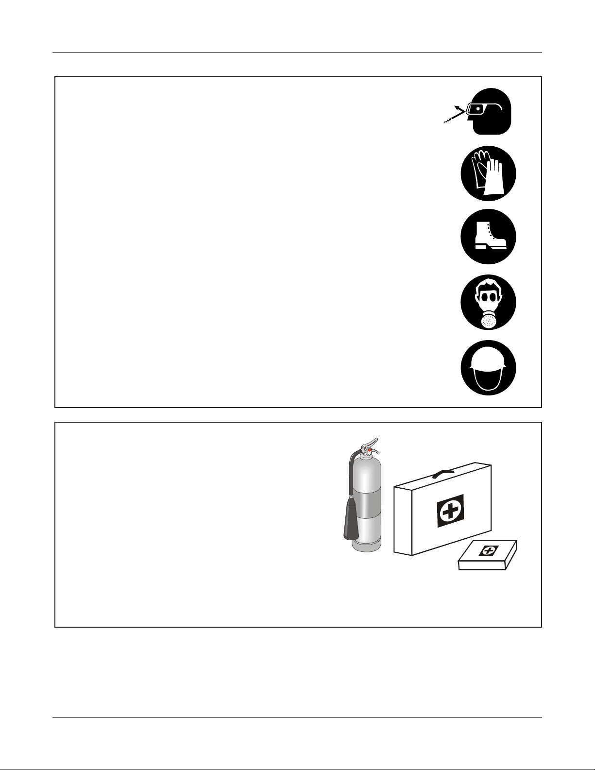
WEAR PROTECTIVE CLOTHING
Wear close fitting clothing and safety equipment
appropriate to the job. Keep hair, loose clothing, &
shoestrings away from rotating & moving parts.
Safety glasses should be worn at all times to
protect eyes from debris.
Wear gloves to protect your hands from sharp
edges on plastic or steel parts.
A respirator may be needed to prevent breathing
potentially toxic fumes and dust.
Wear hard hat and steel toe boots to help protect
your head and toes from falling debris.
Eye Protection
Gloves
Steel Toe
Boots
Respirator
Hard Hat
PREPARE FOR EMERGENCIES
Make sure someone is nearby who is aware of
the proper emergency procedures in the event of
an accident or emergency.
Be prepared if fire starts.
Keep a first aid kit and fire extinguisher handy .
Keep emergency numbers for doctors, ambu-
lance service, hospital, and fire department near
your telephone.
Have Emergency
Equipment Ready.
6
PNEG-1096 Ladder , Safety Cage, & Platforms
Page 7
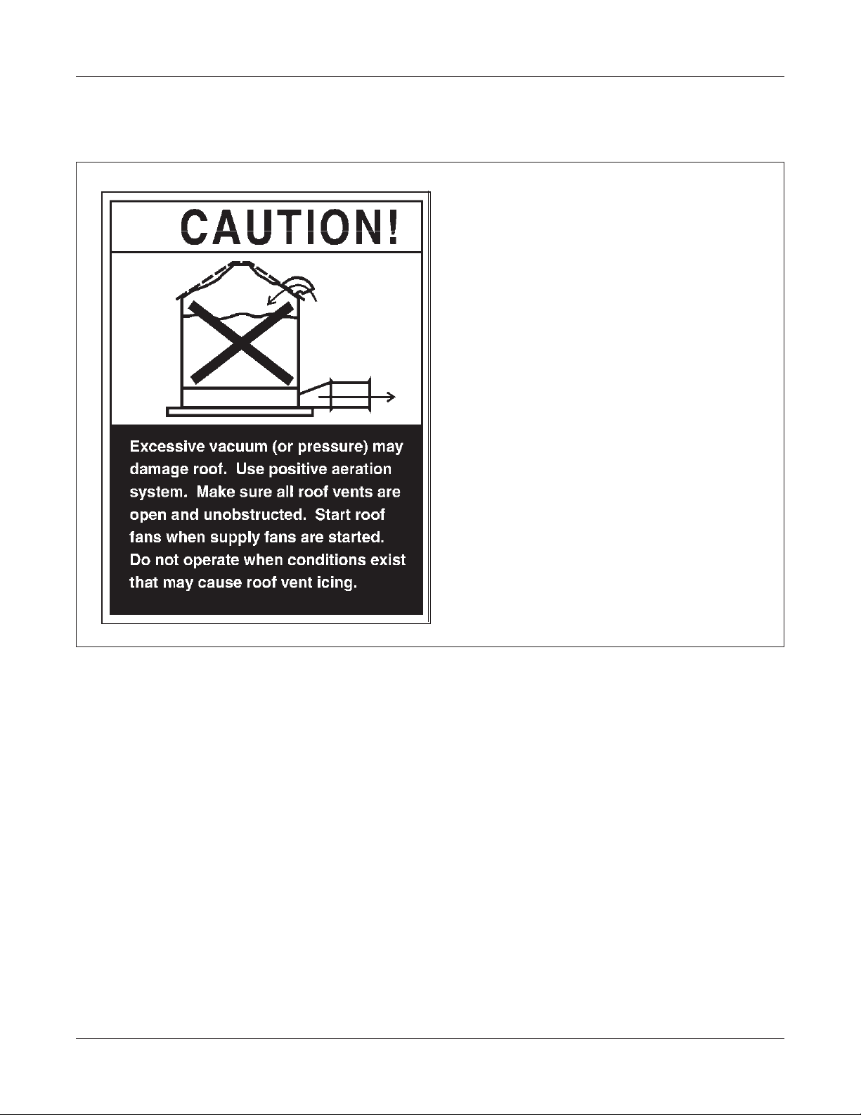
Roof Disclaimer
Roof Damage Warning and Disclaimer
THE MANUFACTURER DOES NOT
WARRANT ANY ROOF DAMAGE
CAUSED BY EXCESSIVE VACUUM
OR INTERNAL PRESSURE FROM
FANS OR OTHER AIR MOVING
SYSTEMS. ADEQUA TE VENTILA TION
AND/OR "MAKEUP AIR" DEVICES
SHOULD BE PROVIDED FOR ALL
POWERED AIR HANDLING SYSTEMS.
THE MANUFACTURER DOES NOT
RECOMMEND THE USE OF
DOWNWARD FLOW SYSTEMS
(SUCTION). SEVERE ROOF DAMAGE
CAN RESULT FROM ANY BLOCKAGE
OF AIR PASSAGES. RUNNING FANS
DURING HIGH HUMIDITY/COLD
WEATHER CONDITIONS CAN CAUSE
AIR EXHAUST OR INTAKE PORTS TO
FREEZE.
PNEG-1096 Ladder , Safety Cage, & Platforms
7
Page 8
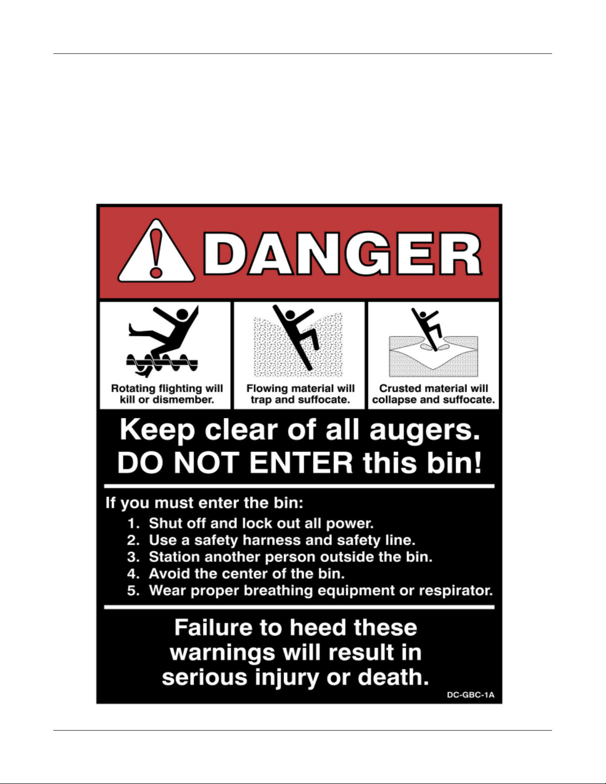
Safety Decal
ATTENTION: The decal shown below should be present on the inside of the two ring door cover , 24"
porthole door cover and the roof manway cover. If a decal has been damaged or is missing in any of these
locations contact the manufacturer for a free replacement decal.
DECALS
P.O. BOX 20
ASSUMPTION, IL. 62510-0020
(217) 226-4421
8
PNEG-1096 Ladder , Safety Cage, & Platforms
Page 9
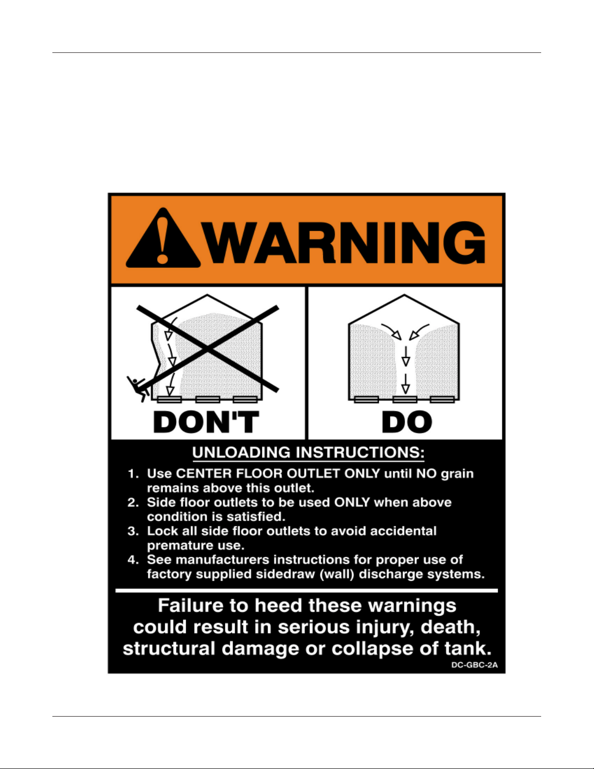
Safety Decal
ATTENTION: The decal shown below should be present on the outside of the two ring door cover, 24”
porthole door cover and roof manway cover. If a decal has been damaged or is missing in any of these
locations contact the manufacturer for a free replacement decal.
DECALS
P .O. BOX 20
ASSUMPTION, IL. 62510-00020
(217)-226-4421
PNEG-1096 Ladder , Safety Cage, & Platforms
9
Page 10

2.66 INSIDE STIFFENED
THIS SECTION
CORRUGATED
FOR 2.66"
GRAIN BINS
INSIDE STIFFENED
10
PNEG-1096 Ladder , Safety Cage, & Platforms
Page 11
2.66 INSIDE STIFFENED
LADDER SAFETY CAGE, AND PLATFORM INSTRUCTIONS
All packages have been structured with the correct components for each ring height grain
bin from 6 rings to 37 rings. Be sure and follow the complete instruction sheets for correct
placement of parts. Failure to do so may result in improper fit of parts or shortage of parts. Read
through the complete set of instructions before proceeding with erection of grain bin.
Considerable thought must be given as to location of ladders and platforms in relation to other
equipment and structures.
STARTING LOCATION OF LADDERS
Ladder placement is very critical as to assure proper fit of all parts later on as safety cage is
bolted in place. Locate the proper place for the roof ladder and manway this will establish the
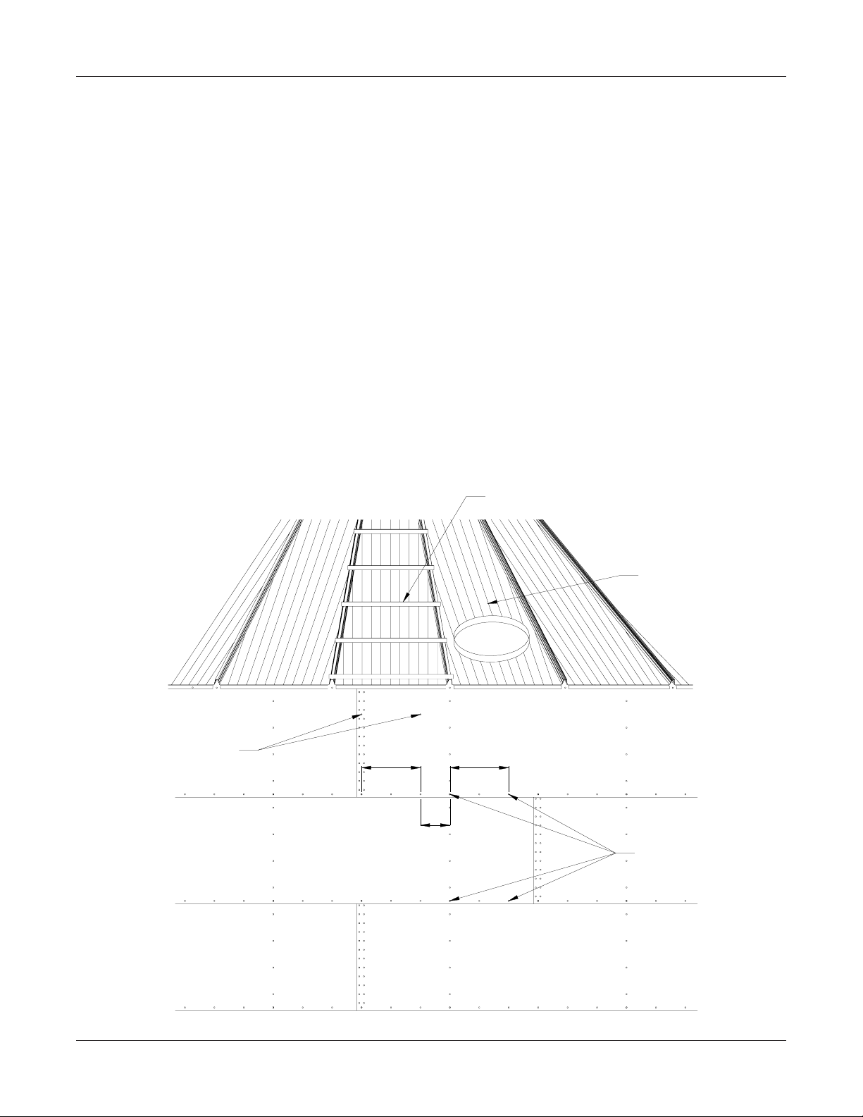
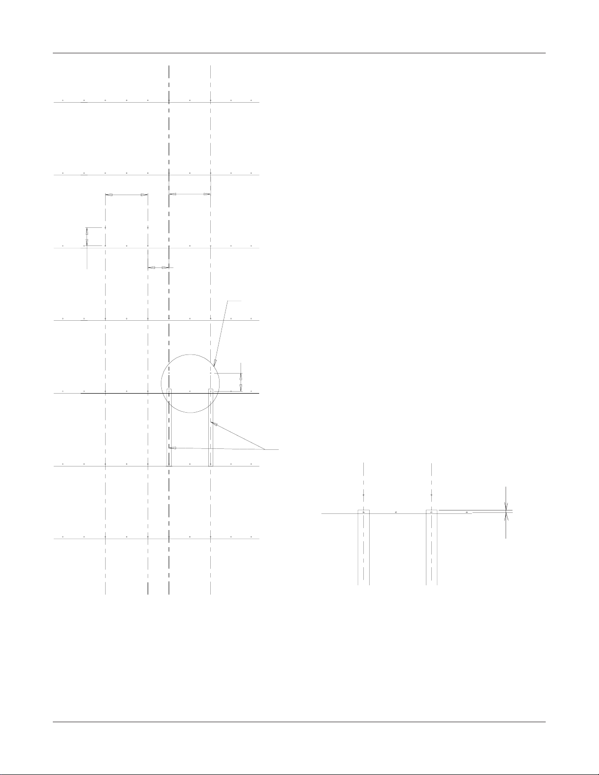
location of the ladder . Ladder must be centered directly below the roof ladder. Refer to the diagram below for proper location of field drilled holes (3/8"). Holes must be 18 3/4" apart and 8"
below the top horizontal row of holes directly in line with the holes to be used for the platform
mounting angle. Platform must be located 9 3/8" to the right of the ladder holes. All of these
dimensions are very critical to assure proper fit of all parts!
FIELD DRILL
3/8" HOLES (2)
ROOF LADDER
MANWAY PANEL
18 3/4"18 3/4"
9 3/8"
HOLES FOR PLATFORM
REV . 9/12/-00
PNEG-1096 Ladder , Safety Cage, & Platforms
11
Page 12
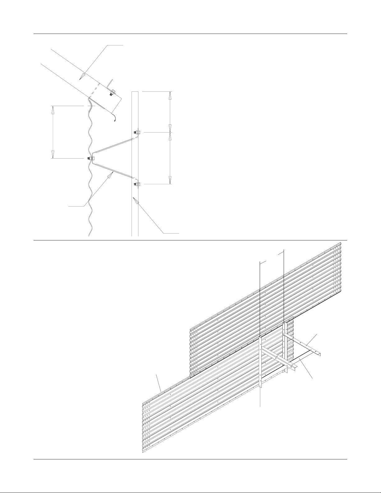
2.66 INSIDE STIFFENED
Roof Sheet
8"
Outside
Standoff
LS-121
6.1/4"
8"
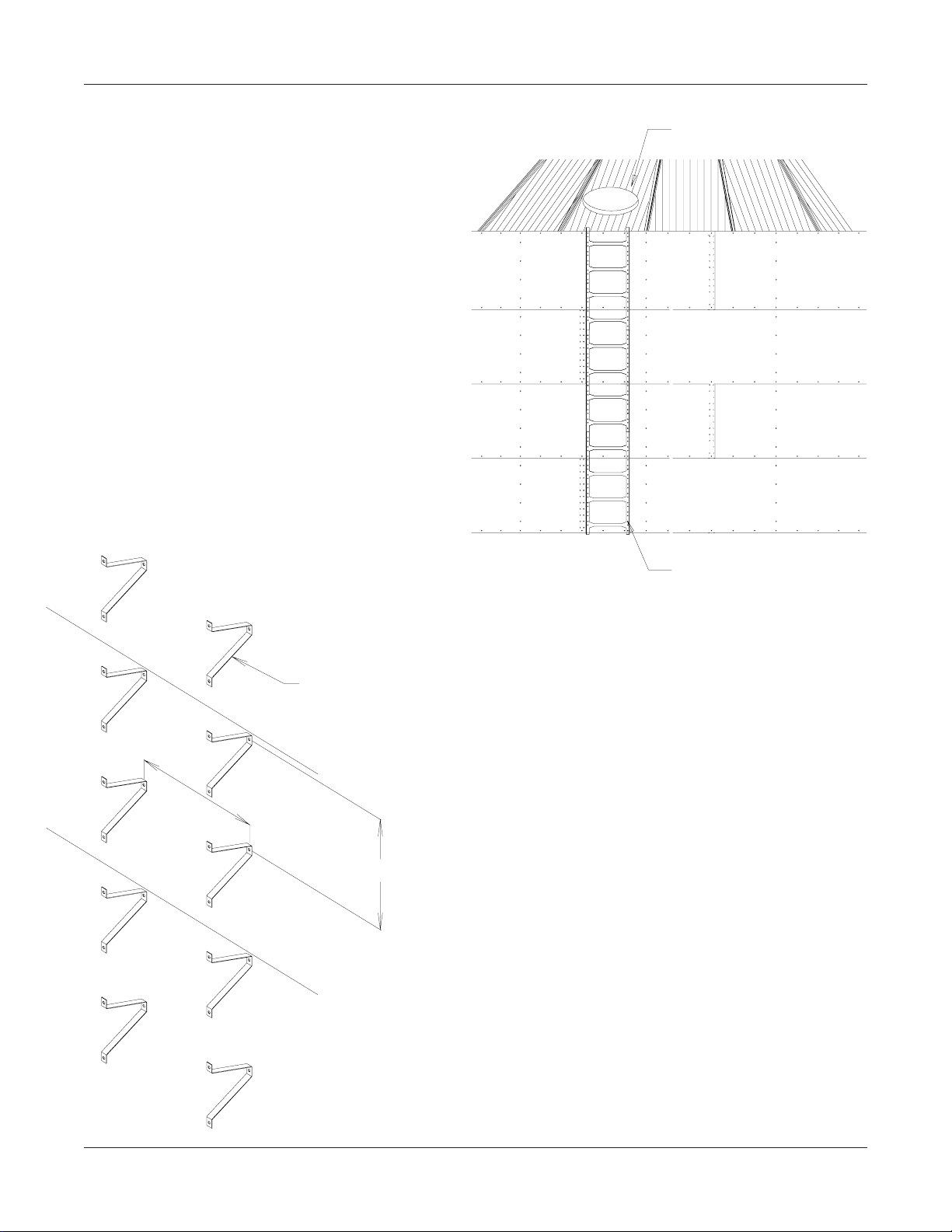
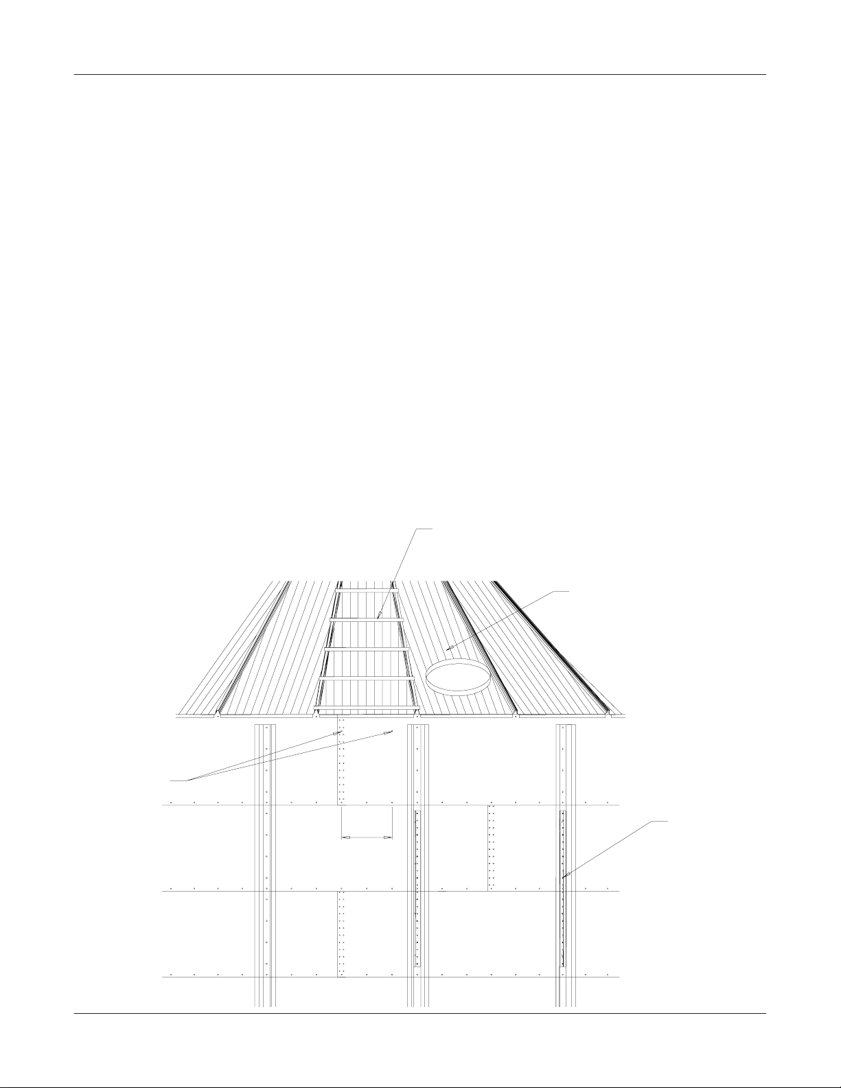
LADDER PLACEMENT
Ladder placement on the grain bin is very
important at this time. Refer to the diagram
at the left and follow the correct dimensions as
shown. Ladder standoff must be located
8" below the horizontal seam. Check your
ladder to make sure the ladder rung dimples
are to the top surface. Attach ladder to the
standoffs using the holes located 6 1/4"
from the end of ladder section. Use 5/16" x
3/4" bin bolts for these connections. Now all
standoffs must be located in horizontal seam
holes (repeating every 32") until reaching
the first rest platform. Refer to the section
in these instructions that references the location of intermediate rest platforms for further
hole locations.
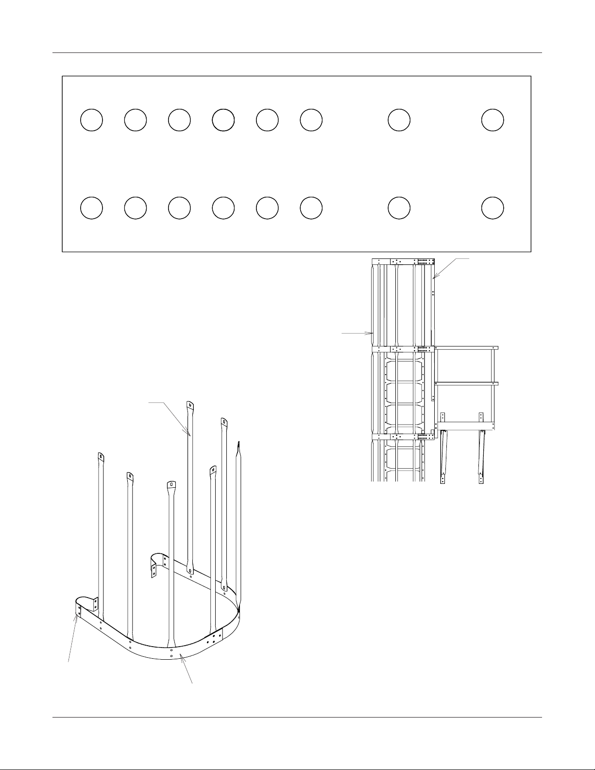
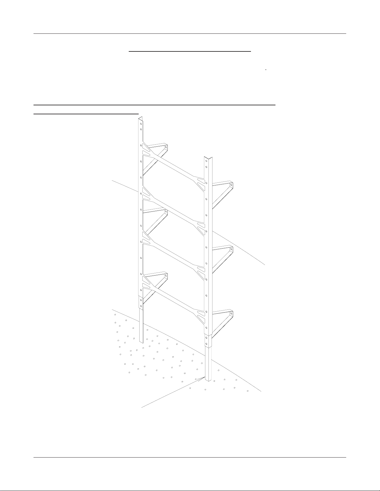
PLATFORM SUPPORT ASSEMBLY
When starting the platform support, you
must attach the mounting angle to the
sidewall of the grain bin. Refer back to the
first page for the correct holes to be used
by the platform. Attach the angle using
5/16" x 3/4" bolts and nuts, tighten at this
time. Next, bolt the support angle to the
mounting angle again using the proper
holes. Attach the brace angle to the
mounting angle as shown in the diagram
at left. Use 5/16" x 3/4" bolts and nuts for
all connections.
Horizontal Seam
Ladder Section
LDR-4002
18 3/4''
LS-370
Support Angle
LS-369
Brace Angle
30 3/4"
12
LS-6705
Mounting Angle 34"
REV. 10/9/01
PNEG-1096 Ladder , Safety Cage, & Platforms
Page 13
2.66 INSIDE STIFFENED
FIELD DRILL 5/16'' HOLES
(4) PER BRACE
3
4
5
1
2
6
REF. NO. DESCRIPTION PART NO.
Note: Reference previous page for the
first ladder standoff starting location.
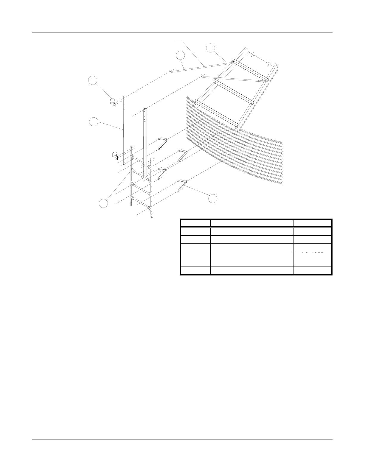
EXTENSION RAILS
1 END TUBE LS-6616
2 CENTER TUBE LS-6615
3 SAFETY CAGE BRACKET LS-4349
4 SAFETY CAGE EXT. RAIL LS-4355
5 LADDER SECTION LDR-4002
6 OUTSIDE STANDOFF LS-121
LS-6696
Extension rails are provided to extend the side rails of the ladder above the eave of the
roof and to support the safety cage at that point. T wo rails have been provided, one for each
side of the ladder . Refer to diagram above for proper location and assembly of the extension
rails in relation to the ladder . Use 5/16" x 3/4" bolts and nuts to attach the ladder. Tighten the
bolts at this time.
EAVE ADJUSTABLE BRACES
After extension rails are firmly attached, the adjustable braces must be attached at this
time. A larger diameter tube and two smaller diameter tubes are used to make up one
adjustable brace. Slip the smaller tubes inside the larger tube and attach one smaller tube to
the top of the extension rail. Adjust the other smaller tube so the bottom of the flattened tube
reaches the roof rib. Field drill four 5/16" holes through both large and small adjustable tubes
and bolt together using 1/4" x 1.1/2" bolts and nuts. This will keep the adjustable brace from
slipping.
Attach the safety cage brackets to the extension rail and ladder as shown in the
diagram. Brackets must be placed every 44". This will occur at every ladder joint. Use 5/16" x
3/4" bolts and nuts.
REV. 9/11/01
PNEG-1096 Ladder , Safety Cage, & Platforms
13
Page 14
2.66 INSIDE STIFFENED
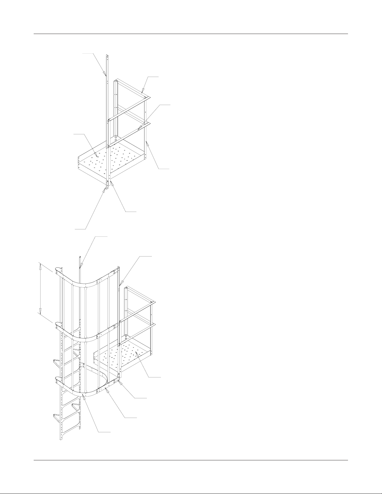
LS-6697
Safety Cage Platform
Extension Angles
(Flours. Green)
LS-373
Platform
LS-5283
SafetyCage Hoop
Adapter Angle
41" (T yp.)
LS-294
End Handrail
24.3/8" (White)
LS-295
Front Handrail
31.7/8" (Black)
LS-371
Platform Vertical
Angle 42" (Yellow)
LS-372
Vert. Entrance Angle
46" (Orange)
Extension Rails or Ladder
(Ladder to be used on
Intermediate Platform)
Extension Angle
Platform
LS-5285 Safety
Cage Hoop
Adjuster Plate
LS-5284 Safety Cage
Adapter Hoop
LS-4351 Safety Cage
Hoof Half
EXTENSION ANGLE DETAIL
PLATFORM AND HANDRAIL
ASSEMBLY
Start by attaching the platform itself to
the platform support using 5/16" x 3/4"
bolts and nuts. Place all the vertical
angles in place, making sure to place
the vertical entrance angle to the left
front corner of the platform. After all vertical angles are in place attach front and
side handrails as shown in the diagram.
Use 5/16" x 3/4" bolts and nuts in all
connections.
EAVE SAFETY CAGE &
INTERMEDIATE REST PLA TFORM
Before attaching any pieces to the ladder or platform some preassembly will
be required. Take the safety cage hoop
adjuster plate and the safety cage
adapter hoop and bolt together using the
proper holes, (as shown on following
page.) Be sure the proper holes are used
depending on the diameter of the grain
bin. Be sure to use the 5/16" x 3/4" bolt
with the head of the bolt to the inside of
the safety cage. Using the improper
holes will make the safety cage more difficult to assemble. Y ou may now bolt this
assembly to the safety cage hoop half,
tighten bolts as you go. One of the assemblies will take 2 hoop halves and be
positioned just below the platform as
shown in the diagram. Take the assembly and attach to the safety cage bracket
and to the platform extension angle or
the hoop adapter angle. Refer to the diagram for more information. If holes don't
align properly go back and make sure
the ladder and platform are correctly positioned on grain bin in relationship to one
another . Make any corrections necessary
to complete the assembly as shown.
14
REV. 9/13/01
PNEG-1096 Ladder , Safety Cage, & Platforms
Page 15
2.66 INSIDE STIFFENED
WHEN ATTACHING SAFETY CAGE TO PLATFORM, THE HOOP ADJUSTER PLATE MUST BE USED
TO COMPENSATE FOR THE DIFFERENT BIN CURVATURES. NOTE: (THIS PLATE IS NOT NEEDED
FOR 90' & 105' DIAMETER BINS.) BOLT THE PROPER END TO THE EXTENSION ANGLE OR ADAPTER
HOLE. NOW LOCATE PROPER HOLES IN HOOP ADJUSTER PLATE AND BOLT TO THE SAFETY CAGE
ADAPTER HOOP.
12'-15'
21'-24'
18'
30'-33'
27'
36'-42'
48'
60'
75'-78'
72'
EAVE SAFETY CAGE
After all three hoop assemblies are in
place you may attach the 44" vertical
supports from hoop to hoop. This will
require 10 supports, 5 between each
set of hoops. Again use the truss
head bolts with bolt head to the inside
of safety cage.
LS-4353 Safety Cage
44" Vertical Support
LS-4353 Safety Cage
44" Vertical Support
BOLT TO
EXTENSION
ANGLE OR
ADAPTER
ANGLE
LS-6697 Safety
Cage Platform
Extension Angle
LS-4349 Safety Cage
Standard Bracket
REV. 9/14/01
PNEG-1096 Ladder , Safety Cage, & Platforms
LS-4351
Safety Cage
Hoop Half
SAFETY CAGE EXTENSION
The safety cage extension package is designed to be
added on to the bottom of the existing safety cage above
it. Attach the vertical support pieces to the existing hoop
halves above using the 5/16" x 3/4" bolt and nuts. Fasten
the package to the safety cage brackets and attach the
bottom of the vertical supports to the hoop halves and
tighen bolts. Continue to use the extension packages as
the usage chart reflect on the following page.
Whereas you formerly had all extension packages bundled
and listed under the LS-4365LB part number you will now
have a combination of LS-4366LB (A package of two (2)
extension kits) and LS-4365LB (The original single extension kit).
15
Page 16
16
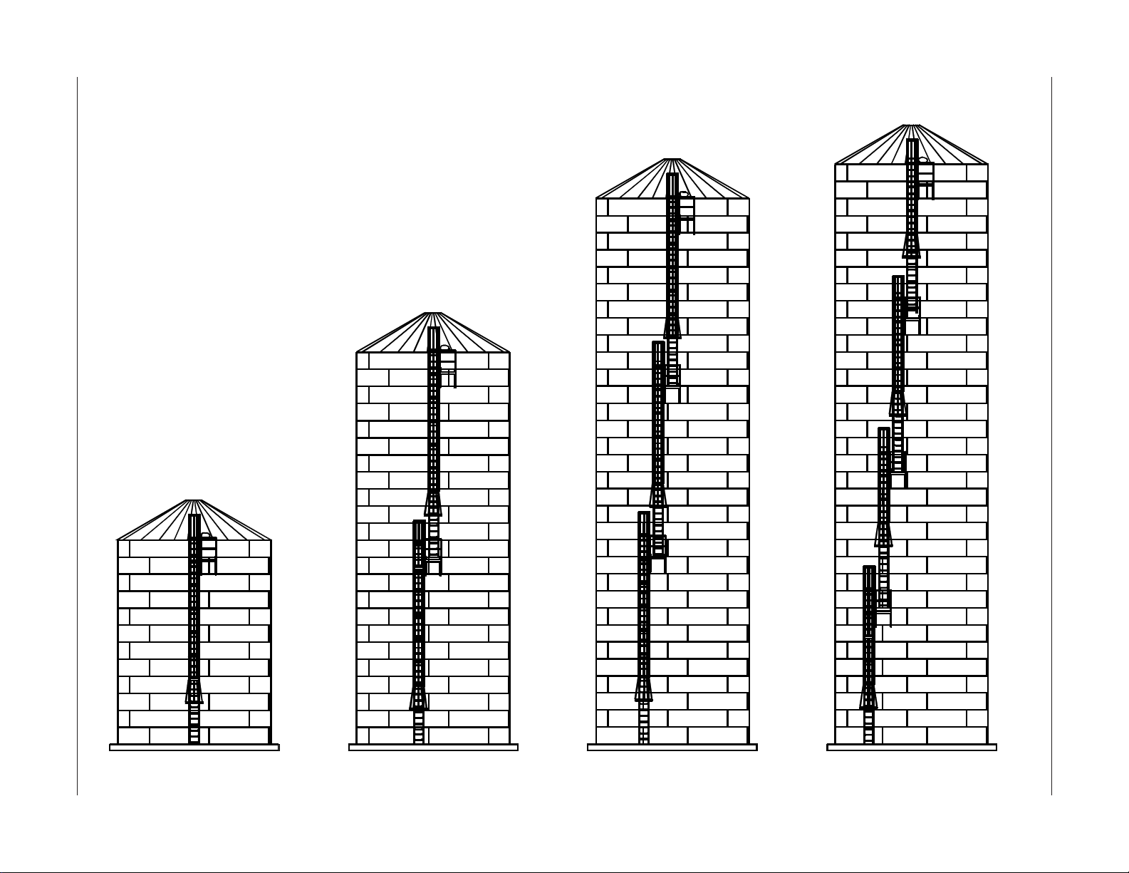
2.66 INSIDE STIFFENED
2.66" INSIDE STIFFENED LADDER
OFFSET AND PLATFORM LAYOUT
PNEG-1096 Ladder , Safety Cage, & Platforms
A
2nd
A
B
2nd
13th
A
B
C
2nd
12th
22nd
A
B
C
2nd
10th
19th
D
12 RINGS 23 RINGS 32 RINGS 34 RINGS
27th
Page 17
PNEG-1096 Ladder, Safety Cage, & Platforms
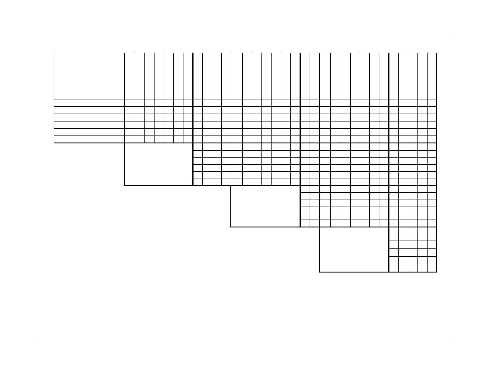
ITEM
Platform Located in Ring22222222222 2222222222 22222222222
Ladder Section (LDR-4002)55677896666 688889966669999977777
Bell Safety Cage (LS-4364LB)111111111111111111111 11111111111
Safety Cage Extension- 1233452222 244445522224444433333
Platform Package 11111111111 1111111111 11111111111
Eave Safey Cage (LS-5289)111111111111 11111111 1 11111111111
LS-5293 6 Rings
LS-5294 7 Rings
LS-5295 8 Rings
LS-5296 9 Rings
LS-5297 10 Rings
LS-5298 11 Rings
LS-5299 12 Rings
B
Platform Located in Ring 9 9 9 9 9 11 11 11 11 13 13 9 9 9 9 12 12 12 12 12 10 10 10 10 10
Ladder Section (LDR-4002)6678 98991091099 9 98899988888
Bell Safety Cage (LS-4364LB)1111 1 11111111 111111111111
Safety Cage Extension11234 34454544 4 43344433333
Platform Package 11111111111111 11111111111
Eave Safey Cage (LS-5289)1111 1 11111111 111111111111
2.66" INSIDE STIFFENED
LADDER OFFSET CHART
LS-5300 13 Rings
LS-5301 14 Rings
LS-5302 15 Rings
LS-5303 16 Rings
LS-5304 17 Rings
LS-5305 18 Rings
LS-5306 19 Rings
LS-5307 20 Rings
LS-5308 21 Rings
LS-5309 22 Rings
LS-5310 23 Rings
LS-5311 24 Rings
LS-5312 25 Rings
LS-5313 26 Rings
LS-5314 27 Rings
LS-5315 28 Rings
LS-5316 29 Rings
LS-5317 30 Rings
LS-5318 31 Rings
LS-5319 32 Rings
LS-6693 33 Rings
LS-6694 34 Rings
C
Platform Located in Ring 18 18 18 18 20 20 22 22 22 19 19 19 19 19
Ladder Section (LDR-4002)78 9 999891088888
Bell Safety Cage (LS-4364LB)11 1 11111111111
Safety Cage Extension233 43434533333
Platform Package 11 111111111111
Eave Safey Cage (LS-5289)11111111111111
D
Platform Located in Ring 27 27 27 27 27
Ladder Section (LDR-4002)789910
Bell Safety Cage (LS-4364LB)11111
Safety Cage Extension23445
Platform Package 11111
Eave Safey Cage (LS-5289)11111
LS-6707 35 Rings
LS-6708 36 Rings
LS-6709 37 Rings
2.66 INSIDE STIFFENED
17
LADDER, SAFETY CAGE, AND PLATFORM USAGE LOCATION CHART
THE CHART ABOVE SHOULD BE IN CONJUNCTION WITH THE DIAGRAMS ON THE PREVIOUS PAGE. FOLLOW THE PROPER LETTER
DESIGNATION FROM THE DIAGRAM TO THE CHART FINDING THE PROPER RING GRAIN BIN AND USE THE AMOUNTS OF LADDERS
AND SAFETY CAGES SHOWN IN CHART BELOW. FOR SAFETY CAGE BELL SECTION SIZE (22" OR 44") SEE CHART ON FOLLOWING
PAGE.
Page 18
2.66 INSIDE STIFFENED
LS-4353 Safety Cage
LS-4354 Safety Cage
44" Vertical Support
22" Vertical Support
LS-4352 Safety Cage
Bell Hoop Half (Red)
LS-4352 Safety Cage
Bell Hoop Half (Red)
SAFETY CAGE BELL SECTIONS (22" or 44")
The safety cage bell section is to be used at the point of termination of the safety cage just
above the rest platforms or the concrete. Refer to the usage chart at the bottom of the page to
determine the correct bell section, attach the vertical supports to the existing hoop halves. Now ,
fasten the bell safety cage brackets (red) to the ladder (some field drilling may be necessary at
this point.) Attach the special bell safety cage hoop halves to the bell brackets and attach the
vertical supports to the bell hoop halves. The vertical supports will have to be bent at the flat
area to allow for the angle of the bell section.
BELL SAFETY CAGE LOCATION CHART
THE BELL SAFETY CAGE PACKAGE GOES ON THE BOTTOM OF A RUN OF SAFETY CAGE AND TERMINATES
JUST ABOVE THE CONCRETE OR PLATFORM. THE CHART GIVES THE SIZE OF BELL SECTION (22" or 44")
TO BE USED WITH THE RUN OF SAFETY CAGE STARTING AT THE TOP RING OF GRAIN BIN COMING DOWN
AND ENDING JUST ABOVE THE PLATFORMS AND/OR CONCRETE. FOLLOW THE DIAGRAMS AND THE
PROPER LETTER DESIGNATION AND REFERENCE THE CHART BELOW FOR PROPER SAFETY CAGE PLACEMENT.
ITEM
LS-5293 6 Rings
LS-5294 7 Rings
LS-5295 8 Rings
LS-5296 9 Rings
LS-5297 10 Rings
LS-5298 11 Rings
LS-5299 12 Rings
LS-5300 13 Rings
LS-5301 14 Rings
LS-5302 15 Rings
LS-5303 16 Rings
LS-5304 17 Rings
LS-5305 18 Rings
LS-5306 19 Rings
LS-5307 20 Rings
LS-5308 21 Rings
LS-5309 22 Rings
LS-5310 23 Rings
LS-5311 24 Rings
LS-5312 25 Rings
LS-5313 26 Rings
LS-5314 27 Rings
LS-5315 28 Rings
LS-5316 29 Rings
LS-5317 30 Rings
LS-5318 31 Rings
LS-5319 32 Rings
LS-6693 33 Rings
LS-6694 34 Rings
LS-6707 35 Rings
Safety Cage Bel l S i ze 44 44 22 22 44 44 22 44 44 44 44 44 22 22 22 22 22 44 44 44 44 44 44 44 44 44 44 44 44 44 44 44
Safety Cage Bell Size 22 44 22 22 22 22 44 44 44 44 22 22 22 22 22 22 22 44 44 44 22 22 22 22 22
Safety Cage Bell Size 22 22 22 44 44 44 44 44 22 22 22 22 22 22
Safety Cage Bell Size 44 44 44 44 44
LS-6708 36 Rings
22" P ACKAGE P ART NUMBER IS LS-4363LB
44" P ACKAGE P ART NUMBER IS LS-4364LB
REV. 9/13/00
18
PNEG-1096 Ladder , Safety Cage, & Platforms
LS-6709 37 Rings
Page 19
8"
18.3/4"
18.3/4"
9.3/8"
2.66 INSIDE STIFFENED
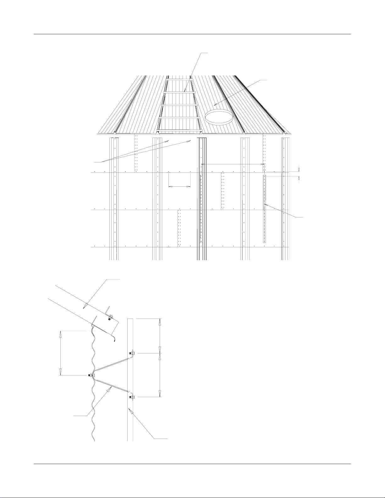
REST PLATFORM OFFSET LOCATION
Follow the diagram at the left of the page very
carefully to insure proper transition of ladder to
platform to ladder offset. Some field drilling will
be necessary at this point to locate the standoffs
correctly . P ay special attention to the dimensions
given. (Holes to be 3/8" dia.) For platform support
assembly reference the platform support
assembly detail.
DETAIL "A"
8"
INTERMEDIATE SAFETY CAGE
PLATFORM MOUNTING ANGLES
1.000"
DETAIL "A"
Follow the instructions refering to the eave safety cage package for this assembly. The only
difference will be the extension rails in the eave safety cage package. This package will have
the ladder instead.
REV. 2-15-95
PNEG-1096 Ladder , Safety Cage, & Platforms
19
Page 20
2.66 INSIDE STIFFENED
INSIDE LADDER PLACEMENT
The inside ladder package includes
the ladders and double the amount
of standoffs. Begin by positioning the
ladder directly under the manhole roof
panel and place the standoffs every 16"
vertically on the sidewall sheets using
the horizontal seam holes for every other
hole location. Us 5/16" x 3/4" bin bolts
to attach the standoffs to the sidewall of
the grain bin. Refer to the diagram on
the right.
Manway Sheet
18.3/4"
LS-121 LADDER
STANDOFFS
16" TYP.
Inside Ladder
INSIDE OF GRAIN BIN
INSIDE LADDER STANDOFFS
REQUIREMENTS
Field drilling will be necessary for the standoffs
located in the middle of the sidewall sheet. Drill
2 holes 3/8" diameter directly in line with the
horizontal seam holes 18 3/4" apart. Continue
down the sidewall with standoffs at every 16"
spacing. Refer to the diagrams at the left.
20
REV. 5-25-95
PNEG-1096 Ladder , Safety Cage, & Platforms
Page 21
2.66 INSIDE STIFFENED
INSIDE LADDER SUPPORTS
After completing the inside ladder it will be necessary to support the bottom of the ladder
to the concrete. Depending on the actual installation, the amount of support may vary . The
supports are not supplied by the manufacturer . Usually the supports can be made of 1" x 1" x 1/
8" angle iron bolted directly to the ladder using 2 bolts 5/16" x 1". If a bin sweep is to be used in
the grain bin, other considerations may be necessary to assure there is no
interference with the equipment.
SUPPORTS ARE NOT SUPPLIED BY GSI
SUPPORTS ARE NOT SUPPLIED
BY GRAIN SYSTEMS, INC.
PNEG-1096 Ladder , Safety Cage, & Platforms
21
Page 22

2.66 OUTSIDE STIFFENED
THIS SECTION
FOR 2.66"
CORRUGATED
GRAIN BINS
OUTSIDE STIFFENED
22
PNEG-1096 Ladder , Safety Cage, & Platforms
Page 23
2.66 OUTSIDE STIFFENED
LADDER SAFETY CAGE, AND PLATFORM INSTRUCTIONS
All packages have been structured with the correct components for each ring height
grain bin from 25'-6" Eave to 98'-7" Eave. Be sure and follow the complete instruction sheets
for correct placement of parts. Failure to do so may result in improper fit of parts or shortage
of parts. Read through the complete set of instructions before proceeding with erection of grain
bin. Considerable thought must be given as to location of ladders and platforms in relation to
other equipment and structures.
STARTING LOCATION OF LADDERS
Ladder placement is very critical as to assure proper fit of all parts later on as safety cage is
bolted in place. Locate the proper place of roof ladder and manway this will establish the
location of the ladder . Ladder must be centered directly below the roof ladder. Refer to the
diagram below for proper location of field drilled holes (3/8"). Holes must be 18 3/4" apart and
8" below the top horizontal row of holes directly in line with the holes pre-punched in the
horizontal seam for the first 2 ladder standoff brackets. The diagrams also show that the
platform uses stiffener holes. Both platform vertical support angles must be located in the
stiffener holes on 2-post tanks and 1 vertical support angles in stiffener holes on 3-post tanks,
as shown in details. These dimensions and locations are very critical to assure proper fit of all
parts.
2-POST
ROOF LADDER
FIELD DRILL
3/8" HOLES (2)
18.3/4"
MANWAY PANEL
TDP-5008N
FLOURS.
GREEN/BLACK
REV. 9/20/00
PNEG-1096 Ladder , Safety Cage, & Platforms
23
Page 24
2.66 OUTSIDE STIFFENED
ROOF LADDER
MANWAY SHEET
FIELD DRILL
3/8" HOLES
8"
Outside Standoff
LS-121
Roof Sheet
6.1/4"
8"
18.3/4"
56.1/4"
4"
FIELD DRILL
3/8" HOLES
LADDER PLACEMENT
Ladder placement on the grain bin is very important at this time. Refer to the diagram at the
left and follow the correct dimensions as shown.
Ladder standoff must be located 8" below the
horizontal seam. Check your ladder to make sure
the ladder rung dimples are to the top surface.
Attach ladder to the standoffs using the holes
located 6 1/4" from the end of ladder section.
Use 5/16" x 3/4" bin bolts for these connections.
Now all standoffs must be located in horizontal
seam holes (repeating every 32") until reaching
the first rest platform. Refer to the section in these
instructions that references the location of intermediate rest platforms for further hole locations.
24
Ladder Section
LDR-4002
PNEG-1096 Ladder , Safety Cage, & Platforms
Page 25

2.66 OUTSIDE STIFFENED
3 - POST / 4 -PANEL PER SIDEWALL SHEET
Roof Sheet
8"
Outside Standoff
LS-121
PNEG-1096 Ladder , Safety Cage, & Platforms
LADDER PLACEMENT
Ladder placement on the grain bin is very important at this time. Refer to the diagram at the
left and follow the correct dimensions as shown.
Ladder standoff must be located 8" below the
horizontal seam. Check your ladder to make sure
6.1/4"
the ladder rung dimples are to the top surface.
Attach ladder to the standoffs using the holes
located 6 1/4" from the end of ladder section.
Use 5/16" x 3/4" bin bolts for these connections.
8"
Now all standoffs must be located in horizontal
seam holes (repeating every 32") until reaching
the first rest platform. Refer to the section in these
instructions that references the location of intermediate rest platforms for further hole locations.
Ladder Section
LDR-4002
25
Page 26

2.66 OUTSIDE STIFFENED
FIELD DRILL 5/16'' HOLES
(4) PER BRACE
1
2
3
4
5
REF. NO. DESCRIPTION PART NO.
Note: Reference previous page for the
first ladder standoff starting location.
6
1 END TUBE LS-6616
2 CENTER TUBE LS-6615
3 SAFETY CAGE BRACKET LS-4349
4 SAFETY CAGE EXT. RAIL LS-4355
5 LADDER SECTION LDR-4002
6 OUTSIDE STANDOFF LS-121
LS-6696
EXTENSION RAILS
Extension rails are provided to extend the side rails of the ladder above the eave of
the roof and to support the safety cage at that point. T wo rails have been provided, one for each
side of the ladder . Refer to diagram above for proper location and assembly of the extension
rails in relation to the ladder . Use 5/16" x 3/4" bolts and nuts to attach the ladder. Tighten the
bolts at this time.
EAVE ADJUSTABLE BRACES
After extension rails are firmly attached, the adjustable braces must be attached at this
time. A larger diameter tube and two smaller diameter tubes are used to make up one adjustable brace. Slip the smaller tubes inside the larger tube and attach one smaller tube to the top
of the extension rail. Adjust the other smaller tube so the bottom of the flattened tube reaches
the roof rib. Field drill four 5/16" holes through both large and small adjustable tubes and bolt
together using 1/4" x 1.1/2" bolts and nuts. This will keep the adjustable brace from slipping.
Attach the safety cage brackets to the extension rail and ladder as shown in the diagram.
Brackets must be placed every 44". This will occur at every ladder joint. Use 5/16" x 3/4" bolts
and nuts.
REV. 9/21/01
26
PNEG-1096 Ladder , Safety Cage, & Platforms
Page 27

PLATFORM ASSEMBLY
2.66 OUTSIDE STIFFENED
NOTE: THE PLATFORM SUPPORTS SHOULD BE
MOUNTED ON THE BIN FIRST . THE PLA TFORM FLOOR
SHOULD THEN BE ASSEMBLED ONTO THE SUPPORT
FRAME. LEAVE PLATFORM SUPPORT TO FL OOR
BRACE BOL TS LOOSE UNTIL FLOOR AND TOEPLA TES
ARE SECURE.
LS-6621 (PINK) VERTICAL
ENTRANCE ANGLE (46'')
LS-6702 (RED)
HANDRAIL (58'')
TDP-5011 PLATFORM
TOE PLATE
TDP-5002 (PINK/BLACK)
HANDRAIL (30'')
Assemble the platform support frame
using 5/16" x 3/4" truss head bolts
and nuts. When attaching vertical
supports to stiffeners or sidewall,
locate the vertical supports according
to the instructions on previous pages.
Now, proceed to the platform floor and
handrails. Align holes on platform
floor with the holes on platform supports and bolt together using 5/16" x
3/4" truss head bolts and nuts. Be
sure and attach platform toe plates at
the same time you attach the platform
floor. Vertical entrance angle will bolt
to platform floor , toeplate and platform
support. Handrail post bolts to platform floor and toeplate as shown.
NOTE: On 18' and smaller 3 post
tanks, move platform support angles
and diagonal support angles away
from wall and field drill vertical
support angle to allow stiffener
clearance.
LS-6703
PLATFORM FLOOR
LS-6698
PLATFORM SUPPORT
LS-6699 (BROWN) LEFT HAND
DIAGONAL SUPPORT ANGLE
TDP-5008N(FL.GREEN/BLACK)
VERTICAL SUPPORT ANGLE
TDP-5011 PLATFORM
TOE PLATE
LS-371 (YELLOW)
HANDRAIL POST (2)
USE UPPER HOLE IN DIAGONAL BRACE WHEN
CONNECTING TO PLATFORM SUPPORT
LS-6700 (BLUE) RIGHT HAND
DIAGONAL SUPPORT ANGLE
(SEE DETAIL)
LS-6701 (ORANGE)
FLOOR BRACE
UPPER HOLE
BRACE DETAIL
REV. 10/3/01
PNEG-1096 Ladder , Safety Cage, & Platforms
27
Page 28

2.66 OUTSIDE STIFFENED
EAVE SAFETY CAGE
Before attaching any pieces to the ladder or platform, some preassembly will be required. Take the safety cage hoop adjuster plates and bolt them onto the extension angle as
shown. Bolt the safety cage adapter hoops and safety cage hoop halves together using the
proper holes, as shown. Be sure to use the 5/16" x 3/4" bolt with the head of the bolt to the
inside of the safety cage. Y ou may now bolt these assemblies to the safety cage brackets and
hoop adjuster plates, tighten bolts as you go. One of the assemblies will take 2 hoop halves
and be positioned just below the platform as shown in the diagram.
44'' TYP.
BOTTOM TO BOTTOM
LS-6696 (GREEN)
EXTENSION RAIL
LS-4351 SAFETY CAGE
HOOP HALF
LS-5284 SAFETY CAGE
HOOP ADAPTERS
LS-5285 SAFETY CAGE
HOOP ADJUSTER PLATE
LS-6697 (FL. GREEN)
EXTENSION ANGLES
LS-6622 SAFETY CAGE
HOOP ADJUSTER ANGLE
28
PLATFORM ASSEMBLY
PNEG-1096 Ladder , Safety Cage, & Platforms
Page 29

VERTICAL SUPPORTS
2.66 OUTSIDE STIFFENED
LS-5286 (FL. GREEN)
LS-6697
SAFETY CAGE PLATFORM
EXTENSION ANGLE
After all three hoop assemblies are in place you
may attach the 44" vertical supports from hoop
assembly to hoop assembly , as shown. This will
require 14 supports, 7 between each set of hoops.
Bolts should have the head of the bolt to the inside
of the safety cage.
SAFETY CAGE
Attach the vertical support pieces to the existing
hoop halves above using the 5/16" x 3/4" bolts
and nuts (with the heads on the inside of the cage).
Fasten two hoop halves together and to the safety
cage brackets. Bolt the safety cage brackets to the
ladder , the supports to the hoop halves and tighten
bolts. Continue in the same manner .
LS-4353 SAFETY CAGE
44" VERTICAL SUPPORT
LS-4349 SAFETY CAGE
STANDARD BRACKET
LS-4353 SAFETY CAGE
44" VERTICAL SUPPORT
Whereas you formerly had all extension packages
bundled and listed under the LS-4365LB part number
you will now have a combination of LS-4366LB
(A package of two (2) extension kits) and LS-4365LB
(The original single extension kit).
44" SAFETY CAGE BELL SECTION
The safety cage bell section is to be used at the
point of termination of the safety cage just above
the concrete or platform (generally 7 to 8 feet).
Attach the vertical supports to the existing hoop
halves. Attach the special bell safety cage hoop
halves to the brackets and attach to the vertical
supports. Fasten the safety cage brackets to the
ladder (some field drilling may be required).
Tighten all bolts at this time. The vertical supports
will have to be bent at the flat area to allow for the
angle of bell section.
REV. 9/25/01
PNEG-1096 Ladder , Safety Cage, & Platforms
LS-4351 SAFETY CAGE
HOOP HALF
LS-4353 SAFETY CAGE
44" VERTICAL SUPPORT
LS-4352 SAFETY CAGE
BELL HOOP HALF
29
Page 30

30
2.66" OUTSIDE STIFFENED LADDER
2.66 OUTSIDE STIFFENED
OFFSET AND PLATFORM LAYOUT
PNEG-1096 Ladder , Safety Cage, & Platforms
A
2nd
A
B
2nd
13th
A
B
C
2nd
12th
22nd
A
B
C
2nd
10th
19th
D
12 RINGS 23 RINGS 32 RINGS 34 RINGS
27th
Page 31

PNEG-1096 Ladder, Safety Cage, & Platforms
ITEM
LSO-25-06
25'-6" EAVE
LSO-29-02
29'-2" EAVE
LSO-32-10
12 RINGS
32'-10" EAVE
LSO-36-06
13 RINGS
36'-6" EAVE
LSO-40-02
15 RINGS
40'-2" EAVE
LSO-43-10
16 RINGS
43'-10" EAVE
LSO-47-06
47'-6" EAVE
LSO-51-02
19 RINGS
51'-2" EAVE
LSO-54-10
20 RINGS
54'-10" EAVE
LSO-58-06
22 RINGS
58'-6" EAVE
LSO-62-02
23 RINGS
62'-2" EAVE
LSO-65-10
Ladder Section
(LDR-4002) 7855667788 9 6777787777
Bell Safety Cage
(LS-4364LB) 1111111111 1 1111111111
Safety Cage
A
Extension 34112233445 233334333 3
Platf orm Pkg.
(LS-6618) 1111111111 1 1111111111
Eave Sfty. Cage
(LS-6619) 1111111111 1 1111111111
Ladder Section
(LDR-4002) 56677889107778888888
Bell Safety Cage
(LS-4364LB) 11111111 1 1111111111
Safety Cage
B
Extension 12233445 5 3334443333
Pl a tf or m Pkg.
(LS-6618) 11111111 1 1111111111
In t. Sfty. Cage
(LS-6620) 11111111 1 1111111111
Ladder Section
(LDR-4002) 778899888 8
Bell Safety Cage
C
(LS-4364LB) 1111111111
Safety Cage
Extension 334455333 3
Platf orm Pkg.
(LS-6618) 1111111111
Int. Sft y. Cage
(LS-6620) 1111111111
24 RINGS
2.66" OUTSIDE STIFFENED
LADDER OFFSET CHART
LADDER, SAFETY CAGE, AND PLATFORM USAGE LOCATION CHART
THE CHART ABOVE SHOULD BE IN CONJUNCTION WITH THE DIAGRAMS ON THE PREVIOUS PAGE. FOLLOW THE PROPER LETTER
DESIGNATION FROM THE DIAGRAM TO THE CHART FINDING THE PROPER RING GRAIN BIN AND USE THE AMOUNTS OF LADDERS
31
AND SAFETY CAGES SHOWN IN CHART BELOW. FOR 44" SAFETY CAGE BELL SECTION SEE FOLLOWING PAGE.
65'-10" EAVE
LSO-69-06
26 RINGS
D
69'-6" EAVE
LSO-73-02
27 RINGS
73'-2" EAVE
LSO-76-10
29 RINGS
76'-10" EAVE
LSO-80-06
30 RINGS
80'-6" EAVE
LSO-84-02
32 RINGS
84'-2" EAVE
LSO-87-10
33 RINGS
87'-10" EAVE
Ladder Section
(LDR-4002) 7 8 9 10
Bell Safety Cage
(LS-4364LB) 1 1 1 1
Safety Cage
Extens ion 2 3 4 5
Platfor m Pkg.
(LS-6618) 1 1 1 1
In t. Sfty. Cage
(LS-6620) 1 1 1 1
LSO-91-03
34 RINGS
91'-3" EAVE
LSO-94-11
35 RINGS
94'-11" EAVE
LSO-98-07
36 RINGS
98'-7" EAVE
2.66 OUTSIDE STIFFENED
Page 32

2.66 OUTSIDE STIFFENED
SAFETY CAGE BELL SECTIONS
The safety cage bell section is to be used at the point of termination of the safety cage just
above the rest platforms or the concrete. Fasten the bell safety cage brackets (red) to the ladder
(some field drilling may be necessary at this point.) Attach the special bell safety cage hoop
halves to the bell brackets and attach the vertical supports to the bell hoop halves. The vertical
supports will have to be bent at the flat area to allow for the angle of the bell section.
LS-4353 Safety Cage
44" Vertical Support
LS-4352 Safety Cage
Bell Hoop Half (Red)
THE BELL SAFETY CAGE PACKAGE GOES ON THE BOTTOM OF A RUN OF SAFETY CAGE AND TERMINATES
JUST ABOVE THE CONCRETE OR PLATFORM.
REV. 3/25/01
32
PNEG-1096 Ladder , Safety Cage, & Platforms
Page 33

INSIDE LADDER
2.66 OUTSIDE STIFFENED
MANWAY SHEET
INSIDE LADDER PLACEMENT
The inside ladder package includes the ladder
and double the amount of standoffs as the
outside ladder package. Begin by positioning
the ladder directly under the manhole roof
panel and place the standoffs every 16" vertically on the sidewall sheets using the horizontal seam holes for every other hole location.
Use 5/16" x 3/4" bin bolts to attach the standoffs
to the sidewall of the grain bin. Refer to the
diagrams to the left and below .
INSIDE OF GRAIN BIN
INSIDE LADDER STANDOFF
REQUIREMENTS
Field drilling will be necessary for the
standoffs located in the middle of the
sidewall sheet. Drill 2 holes 3/8" diameter
directly in line with the horizontal seam
holes 18.3/4" apart. Continue down the
sidewall with standoffs at every 16"
spacing. Refer to the diagram.
LS-121 LADDER
STANDOFFS
18.3/4"
16" TYP.
(See note concerning
Commercial Hopper T anks)
REV. 9/20/00
PNEG-1096 Ladder , Safety Cage, & Platforms
33
Page 34

2.66 OUTSIDE STIFFENED
INSIDE LADDER SUPPORTS
After completing the inside ladder it will be necessary to support the bottom of the ladder
to the concrete. Depending on the actual installation, the amount of support may vary . The
supports are not supplied by the manufacturer . Usually the supports can be made of 1" x 1" x 1/
8" angle iron bolted directly to the ladder using 2 bolts 5/16" x 1". If a bin sweep is to be used in
the grain bin, other considerations may be necessary to assure there is no interference with the
equipment.
34
SUPPORTS ARE NOT SUPPLIED BY GSI
SUPPORTS ARE NOT SUPPLIED
BY GRAIN SYSTEMS, INC.
PNEG-1096 Ladder , Safety Cage, & Platforms
Page 35

4.00 INSIDE STIFFENED
THIS SECTION
FOR 4.00"
CORRUGATED
GRAIN BINS
INSIDE STIFFENED
PNEG-1096 Ladder , Safety Cage, & Platforms
35
Page 36

4.00 INSIDE STIFFENED
LADDER SAFETY CAGE, AND PLATFORM INSTRUCTIONS
All packages have been structured with the correct components for each ring height
grain bin from 4 rings to 24 rings. Be sure and follow the complete instruction sheets for
correct placement of parts. Failure to do so may result in improper fit of parts or shortage of
parts. Read through the complete set of instructions before proceeding with erection of grain
bin. Considerable thought must be given as to location of ladders and platforms in relation to
other equipment and structures.
STARTING LOCATION OF LADDERS
Ladder placement is very critical as to assure proper fit of all parts later on as safety
cage is bolted in place. Locate the proper place for the roof ladder and manway this will
establish the location of the ladder . Ladder must be centered directly below the roof ladder .
Refer to the diagram below for proper location of field drilled holes (3/8"). Holes must be
18 3/4" apart and 8" below the top horizontal row of holes directly in line with the holes to be
used for the platform mounting angle. Platform must be located 9 3/8" to the right of the ladder
holes. All of these dimensions are very critical to assure proper fit of all parts!
FIELD DRILL
3/8" HOLES (2)
18.3/4"
12"
ROOF LADDER
18.3/4"
9.3/8"
MANWAY PANEL
HOLES FOR PLATFORM
36
REV. 9/18/00
PNEG-1096 Ladder , Safety Cage, & Platforms
Page 37

4.00 INSIDE STIFFENED
8"
Outside
Standoffs
LS-121
Roof Sheet
18 3/4''
6.1/4"
8"
Ladder Section
LDR-4002
LADDER PLACEMENT
Ladder placement on the grain bin is very
important at this time. Refer to the diagram at
the left and follow the correct dimensions as
shown. Ladder standoff must be located 8"
below the horizontal seam. Check your ladder
to make sure the ladder rung dimples are to
the top surface. Attach ladder to the standoffs
using the holes located 6 1/4" from the end of
ladder section. Use 5/16" x 3/4" bin bolts for
these connections. Now all standoffs must be
located in horizontal seam holes (repeating
every 44") until reaching the first rest platform.
Refer to the section in these instructions that
references the location of intermediate rest
platforms for further hole locations.
PLATFORM SUPPORT ASSEMBLY
LS-6705
Mounting
Horizontal Seam
PNEG-1096 Ladder , Safety Cage, & Platforms
Angle 35"
When starting the platform support, you
must attach the mounting angle to the
sidewall of the grain bin. Refer back to the
first page for the correct holes to be used
by the platform. Attach the angle using
5/16" x 3/4" bolts and nuts, tighten at this
time. Next, bolt the support angle to the
mounting angle again using the proper
holes. Attach the brace angle to the
mounting angle as shown in the diagram
at left. Use 5/16" x 3/4" bolts and nuts for
all connections.
LS-369
Brace Angle
30-3/4"
LS-370
Support Angle
30.3/4"
REV.10/9/01
37
Page 38

4.00 INSIDE STIFFENED
FIELD DRILL 5/16'' HOLES
(4) PER BRACE
3
4
5
1
2
6
REF. NO. DESCRIPTION PART NO.
1 END TUBE LS-6616
Note: Reference previous page for the
first ladder standoff starting location.
2 CENTER TUBE LS-6615
3 SAFETY CAGE BRACKET LS-4349
4 SAFETY CAGE EXT. RAIL LS-4355
5 LADDER SECTION LDR-4002
6 OUTSIDE STANDOFF LS-121
LS-6696
EXTENSION RAILS
Extension rails are provided to extend the side rails of the ladder above the eave of
the roof and to support the safety cage at that point. T wo rails have been provided, one for each
side of the ladder . Refer to diagram above for proper location and assembly of the extension
rails in relation to the ladder . Use 5/16" x 3/4" bolts and nuts to attach the ladder. Tighten the
bolts at this time.
EAVE ADJUSTABLE BRACES
After extension rails are firmly attached, the adjustable braces must be attached at this
time. A larger diameter tube and two smaller diameter tubes are used to make up one
adjustable brace. Slip the smaller tubes inside the larger tube and attach one smaller tube to
the top of the extension rail. Adjust the other smaller tube so the bottom of the flattened tube
reaches the roof rib. Field drill four 5/16" holes through both large and small adjustable tubes
and bolt together using 1/4" x 1.1/2" bolts and nuts. This will keep the adjustable brace from
slipping.
Attach the safety cage brackets to the extension rail and ladder as shown in the
diagram. Brackets must be placed every 44". This will occur at every ladder joint. Use 5/16" x
3/4" bolts and nuts.
REV. 9/25/01
38
PNEG-1096 Ladder , Safety Cage, & Platforms
Page 39

LS-6697
Safety Cage Platform
Extension Angles
(Flours. Green)
LS-373
Platform
LS-5283
SafetyCage Hoop
Adapter Angle
41" (T yp.)
REV.9/25/01
PNEG-1096 Ladder , Safety Cage, & Platforms
Extension Rails or Ladder
(Ladder to be used on
Intermediate Platform)
LS-5284 Safety Cage
Adapter Hoop
LS-4351 Safety Cage
Hoof Half
LS-294
Front Handrail
24.3/8" (White)
LS-295
Front Handrail
31.7/8" (Black)
LS-371
Platform Vertical
Angle 42" (Y ellow)
LS-372
Vert. Entrance Angle
46" (Orange)
Extension Angle
Platform
LS-5285 Safety
Cage Hoop
Adjuster Plate
4.00 INSIDE STIFFENED
EXTENSION ANGLE DETAIL
PLATFORM AND HANDRAIL
ASSEMBLY
Start by attaching the platform itself to the
platform support using 5/16" x 3/4" bolts and
nuts. Place all the vertical angles in place,
making sure to place the vertical entrance
angle to the left front corner of the platform.
After all vertical angles are in place attach
front and side handrails as shown in the diagram. Use 5/16" x 3/4" bolts and nuts in all
connections.
Safety cage platform extension angles and
safety cage hoop adapter angle will be with
the eave safety cage package. These can
now be attached to the vertical entrance
angle. Refer to the diagram at the left.
EAVE SAFETY CAGE &
INTERMEDIATE REST PLATFORM
Before attaching any pieces to the ladder or
platform some preassembly will be required.
T ake the safety cage hoop adjuster plate and
the safety cage adapter hoop and bolt together using the proper holes, (as shown on
following page.) Be sure the proper holes are
used depending on the diameter of the grain
bin. Be sure to use the 5/16" x 3/4" bolt with
the head of the bolt to the inside of the safety
cage. Using the improper holes will make the
safety cage more difficult to assemble. You
may now bolt this assembly to the safety
cage hoop half, tighten bolts as you go. One
of the assemblies will take 2 hoop halves and
be positioned just below the platform as
shown in the diagram. T ake the assembly and
attach to the safety cage bracket and to the
platform extension angle or the hoop adapter
angle. Refer to the diagram for more information. If holes don't align properly go back
and make sure the ladder and platform are
correctly positioned on grain bin in relationship to one another. Make any corrections
necessary to complete the assembly as
shown.
39
Page 40

4.00 INSIDE STIFFENED
WHEN ATTACHING SAFETY CAGE TO PLATFORM, THE HOOP ADJUSTER PLATE MUST BE USED
TO COMPENSATE FOR THE DIFFERENT BIN CURVATURES. NOTE: (THIS PLATE IS NOT NEEDED
FOR 90' & 105' DIAMETER BINS.) BOLT THE PROPER END TO THE EXTENSION ANGLE OR ADAPTER
HOLE. NOW LOCATE PROPER HOLES IN HOOP ADJUSTER PLATE AND BOLT TO THE SAFETY CAGE
ADAPTER HOOP.
30'-33'
27'
36'-42'
48'
60'
75'-78'
72'
EAVE SAFETY CAGE
After all three hoop assemblies are in place
you may attach the 44" vertical supports from
hoop to hoop. This will require 10 supports, 5
between each set of hoops. Again use the truss
head bolts with bolt head to the inside of safety
cage.
LS-4353 Safety Cage
44" Vertical Support
LS-4353 Safety Cage
44" Vertical Support
BOLT TO
EXTENSION
ANGLE OR
ADAPTER
ANGLE
LS-6697 Safety
Cage Platform
Extension Angle
LS-4349
Safety Cage Standard
Bracket
40
LS-4351
Safety Cage
Hoop Half
SAFETY CAGE EXTENSION
The safety cage extension package is designed to be
added on to the bottom of the existing safety cage above
it. Attach the vertical support pieces to the existing hoop
halves above using the 5/16" x 3/4" bolt and nuts. Fasten the package to the safety cage brackets and attach
the bottom of the vertical supports to the hoop halves
and tighen bolts. Continue to use the extension packages as the usage chart reflect on the following page.
Whereas you formerly had all extension packages
bundled and listed under the LS-4365LB part number you
will now have a combination of LS-4366LB (A package
of two (2) extension kits) and LS-4365LB (The original
single extension kit).
REV. 9/25/01
PNEG-1096 Ladder , Safety Cage, & Platforms
Page 41

PNEG-1096 Ladder , Safety Cage, & Platforms
4.00" INSIDE STIFFENED LADDER
OFFSET AND PLATFORM LAYOUT
A
2nd
A
2nd
10th
A
B
C
2nd
9th
17thB
4.00 INSIDE STIFFENED
41
9 RINGS 17 RINGS
24 RINGS
Page 42

42
PNEG-1096 Ladder , Safety Cage, & Platforms
ITEM
LDR-4019 4 RINGS
Platform Located in Ring
Ladder Section
A
(LDR-4002)
Bell Safety Cage
(LS-4364LB)
Safety Cage Extension
Platform Package
Eave Safety Cage
(LS-5289)
B
LDR-4020 5 RINGS
1-2 1-2 1-2 1-2 1-2 1-2 1-2 1-2 1-2 1-2 1-2 1-2 1-2 1-2 1-2 1-2 1-2 1-2 1-2 1-2 1-2
456789667788996778899
111111111111111111111
-12345223344552334455
111111111111111111111
111111111111111111111
Platform Located in Ring
Ladder Section
(LDR-4002)
Bell Safety Cage
(LS-4364LB)
Safety Cage Extension
Platform Package
Int. Safety Cage
(LS-5290)
4.00" INSIDE STIFFENED
LADDER OFFSET CHART
LDR-4021 6 RINGS
LDR-4022 7 RINGS
LDR-4023 8 RINGS
LDR-4024 9 RINGS
6-7 6-7 7-8 7-8 8-9 8-9 9-10 9-10 6-7 7-8 7-8 8-9 8-9 9-10 9-10
LDR-4025 10 RINGS
LDR-4026 11 RINGS
LDR-4027 12 RINGS
LDR-4028 13 RINGS
LDR-4029 14 RINGS
LDR-4030 15 RINGS
LDR-4031 16 RINGS
LDR-4032 17 RINGS
LDR-4033 18 RINGS
LDR-4034 19 RINGS
LDR-4035 20 RINGS
LDR-4036 21 RINGS
LDR-4037 22 RINGS
LDR-4038 23 RINGS
LDR-4039 24 RINGS
6778899 10889999 10
111111111111111
-12345223344552
111111111111111
111111111111111
Platform Located in Ring
Ladder Section
(LDR-4002)
Bell Safety Cage
(LS-4364LB)
C
Safety Cage Extension
Platform Package
Int. Safety Cage
(LS-5290)
12-13 13-1414-1515-16 15-16 16-17 17-18
8888999
1111111
3333444
1111111
1111111
4.00 INSIDE STIFFENED
LADDER, SAFETY CAGE, AND PLATFORM USAGE LOCATION CHART
THE CHART ABOVE SHOULD BE IN CONJUNCTION WITH THE DIAGRAMS ON THE PREVIOUS PAGE. FOLLOW THE PROPER
LETTER DESIGNATION FROM THE DIAGRAM TO THE CHART FINDING THE PROPER RING GRAIN BIN AND USE THE AMOUNTS
OF LADDERS AND SAFETY CAGES SHOWN IN CHART.
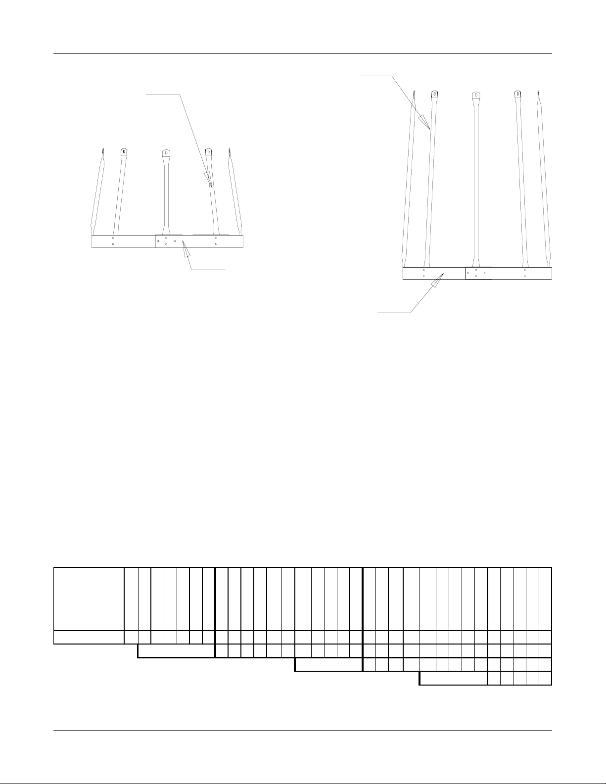
Page 43

SAFETY CAGE BELL SECTIONS
LS-4353 Safety Cage
44" Vertical Support
4.00 INSIDE STIFFENED
LS-4352 Safety Cage Bell Hoop Half (Red)
SAFETY CAGE BELL SECTIONS
The safety cage bell section is to be used at the point of termination of the safety cage just
above the rest platforms or the concrete. Attach the vertical supports to the existing hoop
halves. Now , fasten the bell safety cage brackets (red) to the ladder (some field drilling may be
necessary at this point.) Attach the special bell safety cage hoop halves to the bell brackets
and attach the vertical supports to the bell hoop halves. The vertical supports will have to be
bent at the flat area to allow for the angle of the bell section.
REV. 10-16-95
PNEG-1096 Ladder , Safety Cage, & Platforms
43
Page 44

4.00 INSIDE STIFFENED
REST PLATFORM OFFSET LOCATION
12"
18.3/4"
18.3/4"
9.3/8"
Follow the diagram at the left of the page very
carefully to insure proper transition of ladder to
platform to ladder offset. Some field drilling will
be necessary at this point to locate the standoffs
correctly . P ay special attention to the dimensions
given. (Holes to be 3/8" dia.)
DETAIL "B"
12"
PLATFORM MOUNTING ANGLES
13.000"
12.000"
DETAIL "B"
INTERMEDIATE SAFETY CAGE
Follow the instructions refering to the eave safety cage package for this assembly. The only
difference will be the extension rails in the eave safety cage package. This package will have
the ladder instead.
REV. 11-15-94
44
PNEG-1096 Ladder , Safety Cage, & Platforms
Page 45

INSIDE LADDER PLACEMENT
The inside ladder package includes the ladders and double the amount of standoffs.
Begin by positioning the ladder directly under the manhole roof panel and place the
standoffs every 22" vertically on the sidewall
sheets using the horizontal seam holes for
every other hole location. Us 5/16" x 3/4" bin
bolts to attach the standoffs to the sidewall
of the grain bin. Refer to the diagram on the
right.
4.00 INSIDE STIFFENED
Manway Sheet
18.3/4"
Inside Ladder
INSIDE OF GRAIN BIN
LS-121 LADDER
STANDOFFS
22" TYP.
INSIDE LADDER STANDOFFS REQUIREMENTS
Field drilling will be necessary for the standoffs located in
the middle of the sidewall sheet. Drill 2 holes 3/8" diameter
directly in line with the horizontal seam holes 18 3/4" apart.
Continue down the sidewall with standoffs at every 22"
spacing. Refer to the diagrams at the left.
REV. 5-25-95
PNEG-1096 Ladder , Safety Cage, & Platforms
45
Page 46

4.00 INSIDE STIFFENED
INSIDE LADDER SUPPORTS
After completing the inside ladder it will be necessary to support the bottom of the ladder
to the concrete. Depending on the actual installation, the amount of support may vary . The
supports are not supplied by the manufacturer . Usually the supports can be made of 1" x 1" x 1/
8" angle iron bolted directly to the ladder using 2 bolts 5/16" x 1". If a bin sweep is to be used in
the grain bin, other considerations may be necessary to assure there is no
interference with the equipment.
SUPPORTS ARE NOT SUPPLIED BY GSI
SUPPORTS ARE NOT SUPPLIED
BY GRAIN SYSTEMS, INC.
46
PNEG-1096 Ladder , Safety Cage, & Platforms
Page 47

4.00 OUTSIDE STIFFENED
THIS SECTION
FOR 4.00"
CORRUGATED
GRAIN BINS
OUTSIDE STIFFENED
PNEG-1096 Ladder , Safety Cage, & Platforms
47
Page 48

4.00 OUTSIDE STIFFENED
LADDER SAFETY CAGE, AND PLATFORM INSTRUCTIONS
4 - 9 RINGS ONLY
All packages have been structured with the correct components for each ring height
grain bin from 4 ring to 9 ring. Be sure and follow the complete instruction sheets
for correct placement of parts. Failure to do so may result in improper fit of parts or shortage
of parts. Read through the complete set of instructions before proceeding with erection of grain
bin. Considerable thought must be given as to location of ladders and platforms in relation to
other equipment and structures.
STARTING LOCATION OF LADDERS
Ladder placement is very critical as to assure proper fit of all parts later on as safety cage is
bolted in place. Locate the proper place of roof ladder and manway this will establish the
location of the ladder . Ladder must be centered directly below the roof ladder. Refer to the
diagram below for proper location of field drilled holes (3/8"). Holes must be 18 3/4" apart and
8" below the top horizontal row of holes directly in line with the holes pre-punched in the
horizontal seam for the first 2 ladder standoff brackets. The diagrams also show that the
platform uses stiffener holes. Both platform vertical support angles must be located in the
stiffener holes on 2-post tanks and 1 vertical support angles in stiffener holes on 3-post tanks,
as shown in details. These dimensions and locations are very critical to assure proper fit of all
parts.
2-POST
FIELD DRILL
3/8" HOLES (2)
ROOF LADDER
18.3/4"
MANWAY PANEL
12.00"
LS-6705
48
REV. 10/9/01
PNEG-1096 Ladder , Safety Cage, & Platforms
Page 49

4.00 OUTSIDE STIFFENED
8"
Outside
Standoffs
LS-121
Roof Sheet
6.1/4"
8"
Ladder Section
LDR-4002
LADDER PLACEMENT
Ladder placement on the grain bin is very
important at this time. Refer to the diagram at
the left and follow the correct dimensions as
shown. Ladder standoff must be located 8"
below the horizontal seam. Check your ladder
to make sure the ladder rung dimples are to
the top surface. Attach ladder to the standoffs
using the holes located 6 1/4" from the end of
ladder section. Use 5/16" x 3/4" bin bolts for
these connections. Now all standoffs must be
located in horizontal seam holes (repeating
every 44") until reaching the first rest platform.
Refer to the section in these instructions that
references the location of intermediate rest
platforms for further hole locations.
PLATFORM SUPPORT ASSEMBLY
LS-6705
Mounting
Angle 34''
Horizontal Seam
PNEG-1096 Ladder , Safety Cage, & Platforms
When starting the platform support, you
must attach the mounting angle to the
sidewall of the grain bin. Refer back to the
first page for the correct holes to be used
by the platform. Attach the angle using
5/16" x 3/4" bolts and nuts, tighten at this
time. Next, bolt the support angle to the
mounting angle again using the proper
holes. Attach the brace angle to the
mounting angle as shown in the diagram
at left. Use 5/16" x 3/4" bolts and nuts for
all connections.
LS-370
Support Angle
30.3/4"
LS-369
Brace Angle
30-3/4"
REV.10/10/01
49
Page 50

4.00 OUTSIDE STIFFENED
FIELD DRILL 5/16'' HOLES
(4) PER BRACE
3
4
5
1
2
6
REF. NO. DESCRIPTION PART NO.
1 END TUBE LS-6616
Note: Reference previous page for the
first ladder standoff starting location.
2 CENTER TUBE LS-6615
3 SAFETY CAGE BRACKET LS-4349
4 SAFETY CAGE EXT. RAIL LS-4355
5 LADDER SECTION LDR-4002
6 OUTSIDE STANDOFF LS-121
LS-6696
EXTENSION RAILS
Extension rails are provided to extend the side rails of the ladder above the eave of
the roof and to support the safety cage at that point. T wo rails have been provided, one for each
side of the ladder . Refer to diagram above for proper location and assembly of the extension
rails in relation to the ladder . Use 5/16" x 3/4" bolts and nuts to attach the ladder. Tighten the
bolts at this time.
EAVE ADJUSTABLE BRACES
After extension rails are firmly attached, the adjustable braces must be attached at this
time. A larger diameter tube and two smaller diameter tubes are used to make up one
adjustable brace. Slip the smaller tubes inside the larger tube and attach one smaller tube to
the top of the extension rail. Adjust the other smaller tube so the bottom of the flattened tube
reaches the roof rib. Field drill four 5/16" holes through both large and small adjustable tubes
and bolt together using 1/4" x 1.1/2" bolts and nuts. This will keep the adjustable brace from
slipping.
Attach the safety cage brackets to the extension rail and ladder as shown in the
diagram. Brackets must be placed every 44". This will occur at every ladder joint. Use 5/16" x
3/4" bolts and nuts.
REV. 9/25/01
50
PNEG-1096 Ladder , Safety Cage, & Platforms
Page 51

LS-6697
Safety Cage Platform
Extension Angles
(Flours. Green)
LS-373
Platform
LS-5283
SafetyCage Hoop
Adapter Angle
41" (T yp.)
REV.9/25/01
PNEG-1096 Ladder , Safety Cage, & Platforms
Extension Rails or Ladder
(Ladder to be used on
Intermediate Platform)
LS-5284 Safety Cage
Adapter Hoop
LS-4351 Safety Cage
Hoof Half
LS-295
Front Handrail
31.7/8" (Black)
LS-371
Platform Vertical
Angle 42" (Y ellow)
LS-372
Vert. Entrance Angle
46" (Orange)
Extension Angle
Platform
LS-5285 Safety
Cage Hoop
Adjuster Plate
4.00 OUTSIDE STIFFENED
EXTENSION ANGLE DETAIL
PLATFORM AND HANDRAIL
ASSEMBLY
Start by attaching the platform itself to the
platform support using 5/16" x 3/4" bolts and
nuts. Place all the vertical angles in place,
making sure to place the vertical entrance
angle to the left front corner of the platform.
After all vertical angles are in place attach
front and side handrails as shown in the diagram. Use 5/16" x 3/4" bolts and nuts in all
connections.
Safety cage platform extension angles and
safety cage hoop adapter angle will be with
the eave safety cage package. These can
now be attached to the vertical entrance
angle. Refer to the diagram at the left.
EAVE SAFETY CAGE &
INTERMEDIATE REST PLATFORM
Before attaching any pieces to the ladder or
platform some preassembly will be required.
T ake the safety cage hoop adjuster plate and
the safety cage adapter hoop and bolt together using the proper holes, (as shown on
following page.) Be sure the proper holes are
used depending on the diameter of the grain
bin. Be sure to use the 5/16" x 3/4" bolt with
the head of the bolt to the inside of the safety
cage. Using the improper holes will make the
safety cage more difficult to assemble. You
may now bolt this assembly to the safety
cage hoop half, tighten bolts as you go. One
of the assemblies will take 2 hoop halves and
be positioned just below the platform as
shown in the diagram. T ake the assembly and
attach to the safety cage bracket and to the
platform extension angle or the hoop adapter
angle. Refer to the diagram for more information. If holes don't align properly go back
and make sure the ladder and platform are
correctly positioned on grain bin in relationship to one another. Make any corrections
necessary to complete the assembly as
shown.
51
Page 52

4.00 OUTSIDE STIFFENED
WHEN ATTACHING SAFETY CAGE TO PLATFORM, THE HOOP ADJUSTER PLATE MUST BE USED
TO COMPENSATE FOR THE DIFFERENT BIN CURVATURES. NOTE: (THIS PLATE IS NOT NEEDED
FOR 90' & 105' DIAMETER BINS.) BOLT THE PROPER END TO THE EXTENSION ANGLE OR ADAPTER
HOLE. NOW LOCATE PROPER HOLES IN HOOP ADJUSTER PLATE AND BOLT TO THE SAFETY CAGE
ADAPTER HOOP.
30'-33'
27'
36'-42'
48'
60'
EAVE SAFETY CAGE
After all three hoop assemblies are in place
you may attach the 44" vertical supports from
hoop to hoop. This will require 10 supports, 5
between each set of hoops. Again use the truss
head bolts with bolt head to the inside of safety
cage.
LS-4353 Safety Cage
44" Vertical Support
LS-4353 Safety Cage
44" Vertical Support
BOLT TO
EXTENSION
ANGLE OR
ADAPTER
ANGLE
75'-78'
72'
LS-6697 Safety
Cage Platform
Extension Angle
LS-4349
Safety Cage Standard
Bracket
52
LS-4351
Safety Cage
Hoop Half
SAFETY CAGE EXTENSION
The safety cage extension package is designed to be
added on to the bottom of the existing safety cage above
it. Attach the vertical support pieces to the existing hoop
halves above using the 5/16" x 3/4" bolt and nuts. Fasten the package to the safety cage brackets and attach
the bottom of the vertical supports to the hoop halves
and tighen bolts. Continue to use the extension packages as the usage chart reflect on the following page.
Whereas you formerly had all extension packages
bundled and listed under the LS-4365LB part number you
will now have a combination of LS-4366LB (A package
of two (2) extension kits) and LS-4365LB (The original
single extension kit).
REV. 9/25/01
PNEG-1096 Ladder , Safety Cage, & Platforms
Page 53

INSIDE LADDER
4.00 OUTSIDE STIFFENED
MANWAY SHEET
INSIDE LADDER PLACEMENT
The inside ladder package includes the
ladder
and double the amount of standoffs as the
outside ladder package. Begin by positioning
the ladder directly under the manhole roof
panel and place the standoffs every 22" vertically on the sidewall sheets using the horizontal seam holes for every other hole location.
Use 5/16" x 3/4" bin bolts to attach the standoffs
to the sidewall of the grain bin. Refer to the
diagrams to the left and below .
INSIDE OF GRAIN BIN
INSIDE LADDER STANDOFF
REQUIREMENTS
Field drilling will be necessary for the
standoffs located in the middle of the
sidewall sheet. Drill 2 holes 3/8" diameter
directly in line with the horizontal seam
holes 18.3/4" apart. Continue down the
sidewall with standoffs at every 22"
spacing. Refer to the diagram.
LS-121 LADDER
STANDOFFS
18.3/4"
22" TYP.
NOTE: In Commercial Hopper Tanks with
inside ladders install brackets at 8"
spacing in the bottom two rings.
REV. 9/20/00
PNEG-1096 Ladder , Safety Cage, & Platforms
53
Page 54

4.00 OUTSIDE STIFFENED
INSIDE LADDER SUPPORTS
After completing the inside ladder it will be necessary to support the bottom of the ladder
to the concrete. Depending on the actual installation, the amount of support may vary . The
supports are not supplied by the manufacturer . Usually the supports can be made of 1" x 1" x 1/
8" angle iron bolted directly to the ladder using 2 bolts 5/16" x 1". If a bin sweep is to be used in
the grain bin, other considerations may be necessary to assure there is no interference with the
equipment.
54
SUPPORTS ARE NOT SUPPLIED BY GSI
SUPPORTS ARE NOT SUPPLIED
BY GRAIN SYSTEMS, INC.
PNEG-1096 Ladder , Safety Cage, & Platforms
Page 55

4.00 OUTSIDE STIFFENED
LADDER SAFETY CAGE, AND PLATFORM INSTRUCTIONS
10 - 14 RINGS ONLY
All packages have been structured with the correct components for each ring height
grain bin from 10 ring to 14 ring. Be sure and follow the complete instruction sheets
for correct placement of parts. Failure to do so may result in improper fit of parts or shortage
of parts. Read through the complete set of instructions before proceeding with erection of grain
bin. Considerable thought must be given as to location of ladders and platforms in relation to
other equipment and structures.
STARTING LOCATION OF LADDERS
Ladder placement is very critical as to assure proper fit of all parts later on as safety cage is
bolted in place. Locate the proper place of roof ladder and manway this will establish the
location of the ladder . Ladder must be centered directly below the roof ladder. Refer to the
diagram below for proper location of field drilled holes (3/8"). Holes must be 18 3/4" apart and
8" below the top horizontal row of holes directly in line with the holes pre-punched in the
horizontal seam for the first 2 ladder standoff brackets. The diagrams also show that the
platform uses stiffener holes. Both platform vertical support angles must be located in the
stiffener holes on 2-post tanks and 1 vertical support angles in stiffener holes on 3-post tanks,
as shown in details. These dimensions and locations are very critical to assure proper fit of all
parts.
FIELD DRILL
3/8" HOLES (2)
ROOF LADDER
18.3/4"
2-POST
MANWAY PANEL
8"
TDP-5008N
FLO. GREEN/
BLACK
PNEG-1096 Ladder , Safety Cage, & Platforms
REV. 9/25/01
55
Page 56

4.00 OUTSIDE STIFFENED
8"
Roof Sheet
6.1/4"
8"
Outside
Standoffs
LS-121
Ladder Section
LDR-4002
LADDER PLACEMENT
Ladder placement on the grain bin is very important at this time. Refer to the diagram at the
left and follow the correct dimensions as shown.
Ladder standoff must be located 8" below the
horizontal seam. Check your ladder to make
sure the ladder rung dimples are to the top surface. Attach ladder to the standoffs using the
holes located 6 1/4" from the end of ladder section. Use 5/16" x 3/4" bin bolts for these connections. Now all standoffs must be located in horizontal seam holes (repeating every 44") until
reaching the first rest platform. Refer to the section in these instructions that references the location of intermediate rest platforms for further
hole locations.
56
REV. 4/19/01
PNEG-1096 Ladder , Safety Cage, & Platforms
Page 57

4.00 OUTSIDE STIFFENED
FIELD DRILL 5/16'' HOLES
(4) PER BRACE
3
4
5
1
2
6
REF. NO. DESCRIPTION PART NO.
1 END TUBE LS-6616
Note: Reference previous page for the
first ladder standoff starting location.
2 CENTER TUBE LS-6615
3 SAFETY CAGE BRACKET LS-4349
4 SAFETY CAGE EXT. RAIL LS-4355
5 LADDER SECTION LDR-4002
6 OUTSIDE STANDOFF LS-121
LS-6696
EXTENSION RAILS
Extension rails are provided to extend the side rails of the ladder above the eave of
the roof and to support the safety cage at that point. T wo rails have been provided, one for each
side of the ladder . Refer to diagram above for proper location and assembly of the extension
rails in relation to the ladder . Use 5/16" x 3/4" bolts and nuts to attach the ladder. Tighten the
bolts at this time.
EAVE ADJUSTABLE BRACES
After extension rails are firmly attached, the adjustable braces must be attached at this
time. A larger diameter tube and two smaller diameter tubes are used to make up one
adjustable brace. Slip the smaller tubes inside the larger tube and attach one smaller tube to
the top of the extension rail. Adjust the other smaller tube so the bottom of the flattened tube
reaches the roof rib. Field drill four 5/16" holes through both large and small adjustable tubes
and bolt together using 1/4" x 1.1/2" bolts and nuts. This will keep the adjustable brace from
slipping.
Attach the safety cage brackets to the extension rail and ladder as shown in the
diagram. Brackets must be placed every 44". This will occur at every ladder joint. Use 5/16" x
3/4" bolts and nuts.
REV. 9/25/01
PNEG-1096 Ladder , Safety Cage, & Platforms
57
Page 58

4.00 OUTSIDE STIFFENED
PLATFORM ASSEMBLY
NOTE: THE PLATFORM SUPPORTS SHOULD BE
MOUNTED ON THE BIN FIRST . THE PLA TFORM FLOOR
SHOULD THEN BE ASSEMBLED ONTO THE SUPPORT
FRAME. LEAVE PLATFORM SUPPORT TO FL OOR
BRACE BOLTS L OOSE UNTIL FLOOR AND TOEPLA TES
ARE SECURE.
LS-6621 (PINK) VERTICAL
ENTRANCE ANGLE (46'')
LS-6702 (RED)
HANDRAIL (58'')
TDP-5011 PLATFORM
TOE PLATE
TDP-5002 (PINK/BLACK)
HANDRAIL (30'')
Assemble the platform support frame
using 5/16" x 3/4" truss head bolts
and nuts. When attaching vertical
supports to stiffeners or sidewall,
locate the vertical supports according
to the instructions on previous pages.
Now , proceed to the platform floor and
handrails. Align holes on platform
floor with the holes on platform supports and bolt together using 5/16" x
3/4" truss head bolts and nuts. Be
sure and attach platform toe plates at
the same time you attach the platform
floor. Vertical entrance angle will bolt
to platform floor , toeplate and platform
support. Handrail post bolts to platform floor and toeplate as shown.
NOTE: On 18' and smaller 3 post
tanks, move platform support angles
and diagonal support angles away
from wall and field drill vertical
support angle to allow stiffener
clearance.
LS-6703
PLATFORM FLOOR
PLATFORM SUPPORT
LS-6699 (BROWN) LEFT HAND
DIAGONAL SUPPORT ANGLE
TDP-5008N(FL.GREEN/BLACK)
VERTICAL SUPPORT ANGLE
58
LS-6698
TDP-5011 PLATFORM
TOE PLATE
LS-371 (YELLOW)
HANDRAIL POST (2)
USE UPPER HOLE IN DIAGONAL BRACE WHEN
CONNECTING TO PLATFORM SUPPORT
LS-6700 (BLUE) RIGHT HAND
DIAGONAL SUPPORT ANGLE
(SEE DETAIL)
LS-6701 (ORANGE)
FLOOR BRACE
UPPER HOLE
BRACE DETAIL
REV. 9/24/01
PNEG-1096 Ladder , Safety Cage, & Platforms
Page 59

PNEG-1096 Ladder , Safety Cage, & Platforms
REV. 9/26/01
ITEM
4.00" OUTSIDE STIFFENED LADDER
OFFSET AND PLATFORM LAYOUT
Platform Located in Ring
A
Ladder Section
(LDR-4002)
Bell Safety Cage
(LS-4364LB)
Safety Cage Extension
Platform Package
Eave Safety Cage
(LS-5289)
B
LDR-4019 4 RINGS
LDR-4020 5 RINGS
LDR-4021 6 RINGS
LDR-4022 7 RINGS
LDR-4023 8 RINGS
LDR-4024 9 RINGS
LSO-36-06 10 RINGS
LSO-40-02 11 RINGS
222222222 2 2
556775 566 7 7
111111111 1 1
-12345123 3 3
111111111 1 1
111111111 1 1
Platform Located in Ring
Ladder Section
(LDR-4002)
Bell Safety Cage
(LS-4364LB)
Safety Cage Extension
Platform Package
Eave Safety Cage
(LS-6620)
9 9 9 9 9
6 6 7 7 7
1 1 1 1 1
2 2 3 3 4
1 1 1 1 1
1 1 1 1 1
LSO-47-06 13 RINGS
LSO-43-10 12 RINGS
LSO-51-02 14 RINGS
A
9 RINGS
LADDER, SAFETY CAGE, AND PLATFORM USAGE LOCATION CHART
THE CHART ABOVE SHOULD BE IN CONJUNCTION WITH THE DIAGRAMS ON THiS PAGE. FOLLOW THE PROPER LET TER
DESIGNATION FROM THE DIAGRAM TO THE CHART FINDING THE PROPER RING GRAIN BIN AND USE THE AMOUNTS OF
59
LADDERS AND SAFETY CAGES SHOWN IN CHART.
2nd
A
B
2nd
9th
4.00 OUTSIDE STIFFENED
14 RINGS
Page 60

4.00 OUTSIDE STIFFENED
EAVE SAFETY CAGE
Before attaching any pieces to the ladder or platform, some preassembly will be required. Take the safety cage hoop adjuster plates and bolt them onto the extension angle as
shown. Bolt the safety cage adapter hoops and safety cage hoop halves together using the
proper holes, as shown. Be sure to use the 5/16" x 3/4" bolt with the head of the bolt to the
inside of the safety cage. Y ou may now bolt these assemblies to the safety cage brackets and
hoop adjuster plates, tighten bolts as you go. One of the assemblies will take 2 hoop halves
and be positioned just below the platform as shown in the diagram.
44'' TYP.
BOTTOM TO BOTTOM
LS-6698 (GREEN)
EXTENSION RAIL
LS-4351 SAFETY CAGE
HOOP HALF
LS-5284 SAFETY CAGE
HOOP ADAPTERS
LS-5285 SAFETY CAGE
HOOP ADJUSTER PLATE
LS-6697 (FL. GREEN)
EXTENSION ANGLES
LS-6622 SAFETY CAGE
HOOP ADJUSTER ANGLE
60
PLATFORM ASSEMBLY
PNEG-1096 Ladder , Safety Cage, & Platforms
Page 61

VERTICAL SUPPORTS
4.00 OUTSIDE STIFFENED
LS-6697
LS-5286 (FL. GREEN)
SAFETY CAGE PLATFORM
EXTENSION ANGLE
After all three hoop assemblies are in place you
may attach the 44" vertical supports from hoop
assembly to hoop assembly , as shown. This will
require 14 supports, 7 between each set of hoops.
Bolts should have the head of the bolt to the inside
of the safety cage.
SAFETY CAGE
Attach the vertical support pieces to the existing
hoop halves above using the 5/16" x 3/4" bolts
and nuts (with the heads on the inside of the cage).
Fasten two hoop halves together and to the safety
cage brackets. Bolt the safety cage brackets to the
ladder , the supports to the hoop halves and tighten
bolts. Continue in the same manner .
LS-4353 SAFETY CAGE
44" VERTICAL SUPPORT
LS-4349 SAFETY CAGE
STANDARD BRACKET
LS-4353 SAFETY CAGE
44" VERTICAL SUPPORT
Whereas you formerly had all extension packages
bundled and listed under the LS-4365LB part number
you will now have a combination of LS-4366LB
(A package of two (2) extension kits) and LS-4365LB
(The original single extension kit).
44" SAFETY CAGE BELL SECTION
The safety cage bell section is to be used at the
point of termination of the safety cage just above
the concrete or platform (generally 7 to 8 feet).
Attach the vertical supports to the existing hoop
halves. Attach the special bell safety cage hoop
halves to the brackets and attach to the vertical
supports. Fasten the safety cage brackets to the
ladder (some field drilling may be required).
Tighten all bolts at this time. The vertical supports
will have to be bent at the flat area to allow for tne
angle of bell section.
REV. 926/01
PNEG-1096 Ladder , Safety Cage, & Platforms
LS-4351 SAFETY CAGE
HOOP HALF
LS-4353 SAFETY CAGE
44" VERTICAL SUPPORT
LS-4352 SAFETY CAGE
BELL HOOP HALF
61
Page 62

4.00 OUTSIDE STIFFENED
9.3/8"
18.3/4"
9.3/8''
UPPER
LADDER
18.3/4"
8.00''
LOWER
LADDER
REST PLATFORM OFFSET LOCATION
Follow the diagram above, very carefully to
insure proper transition of ladder to platform to
ladder offset. Some field drilling will be necessary
at this point to locate the standoffs correctly . Pay
special attention to the dimensions given. (Holes
to be 3/8" dia.)
INTERMEDIATE SAFETY CAGE
Follow the instructions refering to the eave safety
cage package for this assembly . The only difference
will be the extension rails in the eave safety cage
package. This package will have the ladder instead.
62
PLATFORM MOUNTING ANGLES
8.00''
REV . 10/10/01
PNEG-1096 Ladder , Safety Cage, & Platforms
Page 63

INSIDE LADDER
4.00 OUTSIDE STIFFENED
MANWAY SHEET
INSIDE LADDER PLACEMENT
The inside ladder package includes the ladder
and double the amount of standoffs as the
outside ladder package. Begin by positioning
the ladder directly under the manhole roof
panel and place the standoffs every 22" vertically on the sidewall sheets using the horizontal seam holes for every other hole location.
Use 5/16" x 3/4" bin bolts to attach the standoffs
to the sidewall of the grain bin. Refer to the
diagrams to the left and below .
INSIDE OF GRAIN BIN
INSIDE LADDER STANDOFF
REQUIREMENTS
Field drilling will be necessary for the
standoffs located in the middle of the
sidewall sheet. Drill 2 holes 3/8" diameter
directly in line with the horizontal seam
holes 18.3/4" apart. Continue down the
sidewall with standoffs at every 22"
spacing. Refer to the diagram.
LS-121 LADDER
STANDOFFS
18.3/4"
22" TYP.
(See note concerning
Commercial Hopper T anks)
NOTE: In Commercial Hopper Tanks with
inside ladders install brackets at 8"
spacing in the bottom two rings.
REV. 9/20/00
PNEG-1096 Ladder , Safety Cage, & Platforms
63
Page 64

4.00 OUTSIDE STIFFENED
INSIDE LADDER SUPPORTS
After completing the inside ladder it will be necessary to support the bottom of the ladder
to the concrete. Depending on the actual installation, the amount of support may vary . The
supports are not supplied by the manufacturer . Usually the supports can be made of 1" x 1" x 1/
8" angle iron bolted directly to the ladder using 2 bolts 5/16" x 1". If a bin sweep is to be used in
the grain bin, other considerations may be necessary to assure there is no interference with the
equipment.
64
SUPPORTS ARE NOT SUPPLIED BY GSI
SUPPORTS ARE NOT SUPPLIED
BY GRAIN SYSTEMS, INC.
PNEG-1096 Ladder , Safety Cage, & Platforms
Page 65

2.66 COMMERCIAL HOPPER TANKS (NCHT)
THIS SECTION
FOR 2.66" CORRUGATED
COMMERCIAL HOPPER
(NCHT) GRAIN BINS
PNEG-1096 Ladder , Safety Cage, & Platforms
65
Page 66

2.66 COMMERCIAL HOPPER TANKS (NCHT)
2
6
SO
29
02
SO
32
10
32
10
SO
36
06
SO
0
02
0
2
SO
3
10
SO
06
6
SO
1
02
SO
10
10
SO
8
06
SO
62
02
62
2
SO
6
10
6
10
SO
69
06
69
6
SO
3
02
3
2
SO
6
10
6
10
SO
80
06
80
6
SO
8
02
8
2
A
A
-
" EAVE
-
ITEM
S
E
C
T A
I
O
N
Ladder Section
(LDR-4002) 7855667788 9 677778
Bell Safety Cage
(LS-4364LB) 1111111111 1 111111
Safety Cage
Extension 3411223344 5 233334
Platform Pkg.
(LS-6618) 1111111111 1 111111
Eave Sfty. Cage
(LS-6619) 1111111111 1 111111
Ladder Section
(LDR-4002) 5667788910777888
Bell Safety Cage
S
(LS-4364LB) 11111111 1 111111
E
Safety Cag e
C
Extension 12233445 5 333444
T B
Platform Pkg.
I
(LS-6618) 11111111 1 111111
O
Int. Sfty. Cage
N
(LS-6620) 11111111 1 111111
NOTE:
FIRST PLATFORM IS LOCATED IN
THE SECOND RING FROM THE TOP.
SEE 2.66" OUTSIDE STIFFENED
SECTION FOR GENERAL ASSEMBLY.
5'-
LSO-25-06
L
-
" EAVE
-7
'-
L
7
B
C
-
" EAVE
-
'7
L
4-
" EAVE
-
'-
L
" EAVE
4'-
A
B
-
-
-
" EAVE
-
-
'-
29'-2" EAVE
L
36'-6" EAVE
L
-
" EAVE
-4
-4
'-
L
L
4
43'-10" EAVE
S
E
C
T C
I
O
N
-47L
-
" EAVE
-5
L
47'-
51'-2" EAVE
-
" EAVE
-54L
54'-
Ladder Section
(LDR-4002) 778899
Bell Safe ty Cage
(LS-4364LB) 111111
Safe ty Cage
Extension 334455
Platform Pkg.
(LS-6618) 111111
Int. Sfty. Cage
(LS-6620) 111111
-
-5
L
" EAVE
'-
58'-6" EAVE
L
5-
L
-
" EAVE
-
5'-
L
-
" EAVE
-7
'-
L
66
PNEG-1096 Ladder , Safety Cage, & Platforms
Page 67

2.66 COMMERCIAL HOPPER TANKS (NCHT)
LADDER
44"
TYPICAL
SUPPORT
COLUMN
Bin
Diameter
Hopper
Slope
No. of Support
Channels
Hopper Ladder
Brackets
15'-21' 45 3 6
15'-18' 60 5 10
21' 60 6 12
24' 45 4 8
27'-30' 40 4 8
27'-30' 45 5 10
36' 40 5 10
36' 45 6 12
SUPPORT
CHANNEL
FIELD DRILL HOLE
5/16" X 1.1/4" HDW.
OR WELD TO
COLUMN
LADDER
STANDOFF
LADDER SUPPORT DETAIL
LADDER
BRACKET
5/16" X 3/4" HDW.
REV. 9/20/00
PNEG-1096 Ladder , Safety Cage, & Platforms
67
Page 68

2.66 COMMERCIAL HOPPER TANKS (NCHT)
ACCESS TO SIDEWALL DOOR ON COMMERCIAL HOPPER TANK
THE METHOD OF ACCESSING THE SIDEWALL DOOR WILL DEPEND ON HOW THE
SYSTEM WAS ORDERED.
1. IF A SEPARATE ACCESS PACKAGE FOR THE SIDEWALL DOOR (ONE OF THE
LSCHT PACKAGES) YOU WILL SIMPLY INSTALL THE SEPARATE RUN OF LADDER,
HOPPER LADDER SUPPORTS AND PLATFORM AS SHOWN IN PREVIOUS DETAILS,
WITHOUT REGARD TO THE STANDARD ROOF MANWAY LADDER PACKAGE.
2. IF THEY ARE USING THE LSO-ACESPLTF PACKAGE TO ACCESS YOUR
SIDEWALL DOOR YOU MUST PRECISELY LAYOUT THE ROOF MANWAY AND SIDEWALL
MANWAY LOCATIONS SO THAT THE SIDEWALL DOOR MAY BE ACCES SED FROM THE
LADDER PATH OF ASCENT.
3. DOOR ACCESS PLATFORMS WILL BE MOUNTED DIRECTLY TO THE HOPPER
TANK COLUMNS. (AS SHOWN BELOW).
LS-6699
(BROWN) LEFT HAND
DIAGONAL SUPPOR T ANGL
TDP-5008N (FL. GREEN/BLACK
VERTICAL SUPPORT ANGLE
REV . 10/3/01
LS-6698
PLA TFORM SUPPOR T
LS-6701
(ORANGE)
FLOOR BRACE
LS-6700
(BLUE) RIGHT HAND
DIAGONAL SUPPOR T ANGLE
3-1/2''
MINIMUM
1/8
1/8
FIELD WELD BOTH ANGLES
(TDP-5008N) (3 PLCS, 6''
LONG @ 24'' C/C EA. SIDE)
WHEN ATTACHING THE
SIDEW ALL ACCESS DOOR
PLATFORM ONLY. PAINT
ALL FEILD WELDS
6''-24''
6''-24''
68
PNEG-1096 Ladder , Safety Cage, & Platforms
Page 69

4.00 FARM-COM. HOPPER TANK
THIS SECTION
FOR 4.00" CORRUGATED
FARM-COM HOPPER
(FCHT) GRAIN BINS
PNEG-1096 Ladder , Safety Cage, & Platforms
69
Page 70

4.00 FARM-COM. HOPPER TANK
A
A
B
70
S
E
C
T A
I
O
N
ITEM
LSO-25-06
25'-6" EAVE
LSO-29-02
29'-2" EAVE
LSO-32-10
32'-10" EAVE
LSO-36-06
36'-6" EAVE
LSO-40-02
40'-2" EAVE
LSO-43-10
43'-10" EAVE
Ladder Section
(LDR-4002) 7 8 5 5 6 6 7
Bell Safety Cage
(LS-4364LB) 1 1 1 1 1 1 1
Safety Cage
Extension 3411223
Platform Pkg.
(LS-6618) 1111111
Eave Sfty. Cage
(LS-6619) 1111111
Ladder Section
(LDR-4002) 5 6 6 7 7
Bell Safety Cage
S
E
C
T B
I
O
N
(LS-4364LB) 1 1 1 1 1
Safety Cage
Extension 12233
Platform Pkg.
(LS-6618) 1 1 1 1 1
Int. Sfty. C age
(LS-6620) 1 1 1 1 1
LSO-47-06
NOTE: REFERENCE 4.00"
OUTSIDE STIFFENED
SECTION FOR GENERAL
ASSEMBLY.
PNEG-1096 Ladder , Safety Cage, & Platforms
47'-6" EAVE
Page 71

4.00 FARM-COM. HOPPER TANK
LADDER
44"
TYPICAL
SUPPORT
COLUMN
Bin
Diameter
Hopper
Slope
No. of Support
Channels
Hopper Ladder
Brackets
15'-21' 45 3 6
15'-18' 60 5 10
21' 60 6 12
24' 45 4 8
SUPPORT
CHANNEL
FIELD DRILL HOLE
5/16" X 1.1/4" HDW.
OR WELD TO
COLUMN
LADDER
STANDOFF
LADDER SUPPORT DETAIL
LADDER
BRACKET
5/16" X 3/4" HDW.
REV . 9/26/01
PNEG-1096 Ladder , Safety Cage, & Platforms
71
Page 72

4.00 FARM-COM. HOPPER TANK
ACCESS TO SIDEWALL DOOR ON COMMERCIAL HOPPER TANK
THE METHOD OF ACCESSING THE SIDEWALL DOOR WILL DEPEND ON HOW THE
SYSTEM WAS ORDERED.
1. IF A SEPARATE ACCESS PACKAGE FOR THE SIDEWALL DOOR (ONE OF THE
LSCHT PACKAGES) YOU WILL SIMPLY INSTALL THE SEPARATE RUN OF LADDER,
HOPPER LADDER SUPPORTS AND PLATFORM AS SHOWN IN PREVIOUS DETAILS,
WITHOUT REGARD TO THE STANDARD ROOF MANWAY LADDER PACKAGE.
2. IF THEY ARE USING THE LS0-ACESPLTF PACKAGE TO ACCESS YOUR SIDEWALL
DOOR YOU MUST PRECISELY LAYOUT THE ROOF MANWAY AND SIDEWALL MANWAY
LOCATIONS SO THAT THE SIDEWALL DOOR MAY BE ACCES SED FROM THE LADDER
PATH OF ASCENT.
3. DOOR ACCESS PLATFORMS WILL BE MOUNTED DIRECTLY TO THE HOPPER
TANK COLUMNS. (AS SHOWN BELOW).
LS-6699
(BROWN) LEFT HAND
DIAGONAL SUPPOR T ANGL
TDP-5008N (FL. GREEN/BLACK
VERTICAL SUPPORT ANGLE
REV . 10/3/01
LS-6698
PLA TFORM SUPPOR T
LS-6701
(ORANGE)
FLOOR BRACE
LS-6700
(BLUE) RIGHT HAND
DIAGONAL SUPPOR T ANGLE
3-1/2''
MINIMUM
1/8
1/8
FIELD WELD BOTH ANGLES
(TDP-5008N) (3 PLCS, 6''
LONG @ 24'' C/C EA. SIDE)
WHEN ATTACHING THE
SIDEW ALL ACCESS DOOR
PLATFORM ONLY. PAINT
ALL FEILD WELDS
6''-24''
6''-24''
72
PNEG-1096 Ladder , Safety Cage, & Platforms
Page 73

2.66 (OPTIONAL)
THIS SECTION FOR 2.66"
CORRUGATED GRAIN BINS
OPTIONAL - EXTENDED
OUTSIDE STIFFENED
LADDER AND PLATFORM
INSTRUCTIONS FOR
COMMERCIAL TANKS AND
COMMERCIAL HOPPER
TANKS
THE FOLLOWING PAGES SHOW AN OPTIONAL LADDER AND
PLATFORM INSTRUCTIONS.
IF YOU HAVE ANYTHING DIFFERENT FROM WHAT IS TALKED
ABOUT IN THIS MANUAL PLEASE CALL THE MANUFACTURER
PNEG-1096 Ladder , Safety Cage, & Platforms
73
Page 74

2.66 (OPTIONAL)
LADDER EXTENSION
BRACKET BRACE
LS-6704
LADDER
EXTENSION BRACKET
LS-6676
OUTSIDE
STAND-OFF
LS-121
LADDER
SECTION
LDR-4002
LADDER PLACEMENT
Ladder placement on the grain bin is very important at this time. Refer to the diagrams above and
follow the correct dimensions as shown. Ladder extension must be located 8" below the horizontal seam. Check your ladder to make sure the ladder rung dimples are to the top surface. Attach
extension bracket (LS-6676) to sidewall. Extension bracket brace and ladder standoff will attach
to upper hole in extension bracket, refer to diagrams for orientation. Attach ladder to the standoffs
using the holes located 6 1/4" from the end of ladder section. Use 5/16" x 3/4" bin bolts for these
connections. Now all extension brackets must be located in horizontal seam holes (repeating
every 32") until reaching the first rest platform. Extension bracket braces (LS-6704) attach at
every other horizontal seam. Refer to the section in these instructions that references the location
of intermediate rest platforms for further hole locations.
74
PNEG-1096 Ladder , Safety Cage, & Platforms
REV. 10/9/01
Page 75

PLATFORM PACKAGE LS - 6683
2.66 (OPTIONAL)
ENTRANCE ANGLE (1)
LS-6621
FLOOR BRACE (4)
LS-6701
58 in. HANDRAIL (2)
LS-6702
38 in. HANDRAIL (2)
LS-6677
TOE PLATE (2)
LS-6682
SUPPORT ANGLE (2)
LS-6679
RIGHT HAND DIAGONAL
SUPPORT ANGLE LS-6700
SIDEWALL SUPPORT (2)
TDP-5008N
When starting the platform support, you must attach the mounting angle to the
sidewall of the grain bin. Refer back to the first page for the correct holes to be
used by the platform. Attach the angle using 5/16" x 3/4" bolts and nuts, tighten
at this time. Next, bolt the support angle to the mounting angle again using the
proper holes. Attach the brace angle to the mounting angle as shown in the
diagram at left. Use 5/16" x 3/4" bolts and nuts for all connections.
PNEG-1096 Ladder , Safety Cage, & Platforms
75
Page 76

2.66 (OPTIONAL)
PLATFORM PACKAGE LS - 6683 CONNECTION TO A HOPPER TANK
SUPPORT ANGLE (2)
LS-6679
LEFT HAND DIAGONAL
SUPPORT ANGLE LS-6699
3. 1/2 in. MINIMUM
FLOOR BRACE (4)
LS-6701
RIGHT HAND DIAGONAL
SUPPORT ANGLE LS-6700
HOPPER COLUMN
SIDEWALL SUPPORT (2)
TDP-5008N
76
PNEG-1096 Ladder , Safety Cage, & Platforms
Page 77

THE GSI GROUP, INC. WARRANTY
THE GSI GROUP, INC. (“GSI”) WARRANTS ALL PRODUCTS WHICH IT MANUF ACTURES TO BE
FREE OF DEFECTS IN MA TERIAL AND WORKMANSHIP UNDER NORMAL USAGE AND
CONDITIONS FOR A PERIOD OF 12 MONTHS AFTER RETAIL SALE TO THE ORIGINAL END
USER. THE PURCHASER’S SOLE REMEDY AND GSI’S ONLY OBLIGA TION SHALL BE T O
REPAIR OR REPLACE, A T GSI’S OPTION AND EXPENSE, PRODUCTS THA T, IN GSI’S SOLE
JUDGMENT , CONT AIN A MA TERIAL DEFECT DUE TO MA TERIALS OR WORKMANSHIP. ALL
DELIVERY AND SHIPMENT CHARGES T O AND FROM GSI’S F ACTOR Y WILL BE
PURCHASER’S RESPONSIBILITY. EXPENSES INCURRED BY OR ON BEHALF OF THE
PURCHASER WITHOUT PRIOR WRITTEN AUTHORIZATION FROM AN AUTHORIZED
EMPLOYEE OF GSI SHALL BE THE SOLE RESPONSIBILITY OF THE PURCHASER.
EXCEPT FOR THE LIMITED W ARRANTY EXPRESSED ABOVE, GSI MAKES NO FURTHER
WARRANTY OF ANY KIND, EXPRESS OR IMPLIED, INCLUDING, WITHOUT LIMITA TION,
WARRANTIES OF MERCHANT ABILITY OR FITNESS FOR A PARTICULAR PURPOSE OR USE IN
CONNECTION WITH (I) PRODUCT MANUF ACTURED OR SOLD BY GSI OR (II) ANY ADVICE,
INSTRUCTION, RECOMMENDA TION OR SUGGESTION PROVIDED BY AN AGENT,
REPRESENTATIVE OR EMPLOYEE OF GSI REGARDING OR RELA TED TO THE CONFIGURATION,
INST ALLA TION, LAYOUT, SUITABILITY FOR A P AR TICULAR PURPOSE, OR DESIGN OF SUCH
PRODUCTS.
GSI SHALL NOT BE LIABLE FOR ANY DIRECT , INDIRECT, INCIDENTAL OR
CONSEQUENTIAL DAMAGES, INCLUDING, WITHOUT LIMITA TION, LOSS OF ANTICIP A TED PROFITS
OR BENEFITS. PURCHASER’S SOLE AND EXCLUSIVE REMEDY IS AS SET FORTH IN THE LIMITED
WARRANTY EXPRESSED ABOVE, WHICH SHALL NOT EXCEED THE AMOUNT PAID FOR THE
PRODUCT PURCHASED. THIS WARRANTY IS NOT TRANSFERABLE AND APPLIES ONLY TO THE
ORIGINAL PURCHASER. GSI SHALL HA VE NO OBLIGA TION OR RESPONSIBILITY FOR ANY
REPRESENTATIONS OR WARRANTIES MADE BY OR ON BEHALF OF ANY DEALER, AGENT O R
DISTRIBUTOR OF GSI.
GSI ASSUMES NO RESPONSIBILITY FOR CLAIMS RESUL TING FROM ERECTION
DEFECTS OR UNAUTHORIZED MODIFICA TIONS T O PRODUCTS WHICH IT MANUF ACTURED.
MODIFICA TIONS TO PRODUCTS NOT SPECIFICALL Y DELINEA TED IN THE MANUAL
ACCOMP ANYING THE EQUIPMENT A T INITIAL SALE WILL NULLIFY THE PRODUCT WARRANTY
THA T MIGHT HA VE BEEN OTHERWISE A V AILABLE.
THE FOREGOING WARRANTY SHALL NOT EXTEND TO PRODUCTS OR PARTS
WHICH HA VE BEEN DAMAGED BY NEGLIGENT USE, MISUSE, AL TERA TION OR ACCIDENT . THIS
WARRANTY EXTENDS SOLELY TO ONLY PRODUCTS MANUFACTURED BY GSI. THIS W ARRANTY
IS EXCLUSIVE AND IN LIEU OF ALL OTHER W ARRANTIES EXPRESS OR IMPLIED. GSI RESERVES
THE RIGHT TO MAKE DESIGN OR SPECIFICA TION CHANGES A T ANY TIME.
PRIOR TO INST ALLA TION, PURCHASER HAS THE RESPONSIBILITY TO COMPL Y
WITH ALL FEDERAL, STA TE AND LOCAL CODES WHICH MAY APPLY TO THE LOCA TION AND
INST ALLA TION OF PRODUCTS MANUF ACTURED OR SOLD BY GSI.
PHLEGAL: #1832020 v1 (139LG01!.DOC) (revised December 2005)
Page 78

P.O. Box 20
Assumption, Il. 62510-0020
PHONE: (217)226-4421
F AX: (217)226-4420
 Loading...