

Page 1

PNEG-1 09 5
FCDL
4.00" Corrugation Externally Stiffened
Grain Bin
Owner ’s Manual
PNEG-1095
Date: 10-09-12
Page 2

2 PNEG-1095 FCDL 4.00" Corrugation Externally Stiffened Grain Bin
Page 3

Table of Contents
Contents
Chapter 1 Introduction ..........................................................................................................................................4
Chapter 2 Safety .....................................................................................................................................................5
Safety Guidelines .................................................................................................................................. 5
General Safety Statement ..................................................................................................................... 6
Safety Instructions ..................... ... .... .......................................... ... ... ..................................................... 7
Safety Sign-Off Sheet ........................................................................................................................... 9
Proper Storage of Grain Bin/Silo Materials Prior to Construction ....................................................... 10
Chapter 3 Decals ..................................................................................................................................................11
Chapter 4 Storage and Drying Bins ...................................................................................................................14
FCDL Bins ........................................................................................................................................... 14
Bins with Stirring Devices .................................................................................................................... 15
Chapter 5 Foundations ........................................................................................................................................16
Foundation Recommendations ........ ... ... .......................................... ... ... .... ... ... ... .... ... ... ...................... 16
Foundation Forms ..................................... ... .... ... .......................................... ... ... .... ............................ 17
Placement of the Fan Pad: Transitions, Fans and Heaters Only ........................................................ 19
Anchor Bolt Placement ........................................................................................................................ 21
Floating Monolithic Foundation Pad for Bins with up to 5 Rings ......................................................... 24
Frost Free Pad Recommendations ........ ... ... .... ... ... ... .... ... ... ... .......................................... ... .... ... ... ...... 25
Frost Free Pads ..................................................... ... .... ... ... ... ............................................................. 26
Inverted “T” Foundation (3000 PSF Soil Bearing Capacity) ................................................................ 28
Inverted “T” Foundations ..................................................................................................................... 29
Hardware ...................................... ................ ................. ................ ................ ...................................... 31
Bolting Requirements ................................ ... .... ... ... ... .... ... .......................................... ... ... ................... 32
Stiffener and Sidewall Seam Bolts ...................................................................................................... 33
Bolt Usage ........................................................................................................................................... 34
Location of Accessories ...................................................................................................................... 37
Chapter 6 Installation ..........................................................................................................................................38
Sidewall Construction ................... .... ... ... ... ... .... ... ... ... .......................................... .... ... ... ... ................... 38
Caulking and Bolting Sidewall Sheets ................................................................................................. 40
Lifting Jack Usage .................................. ... ... .... ... ... ... .......................................... .... ... ... ...................... 41
FCDL Stiffener and Sidewall Gauges ................................................................................................. 42
Top Stiffener Starting Location ............................................................................................................ 48
42' Through 60' Commercial Roof Stiffener Detail .............................................................................. 49
FCDL Stiffeners ................................................................................................................................... 50
Stiffener Splicing Details ..... .......................................... ... ... ... .... ... ... ................................................... 52
Door Placement .................................................................................................................................. 54
2 Ring Door Installation ....................................................................................................................... 55
Options for 2 Ring Door ...................................................................................................................... 60
Access Door Weldment Assembly Hardware Package (PLS-41985) ..................... ... ... ... ... .... ... ... ... ... 62
Base Angle and Stiffener Shim Installation ......................................................................................... 63
Sidedraw Systems ................................................. ... .... ... ... ... .......................................... ................... 64
Transition Assembly (TR-6919) ....................................................... ... ... .... ... ... ... .... ... ......................... 69
Transition Installation (TR-7048) ............................ ... .... ... ... ... .... ... ... ................................................... 72
Chapter 7 Warranty ..............................................................................................................................................75
PNEG-1095 FCDL 4.00" Corrugation Externally St iffened Grain Bin 3
Page 4

1. Introduction
READ THIS MANUAL carefully to learn how to properly use and install equipment. Failure to do so could
result in personal injury or equipment damage.
INSPECT the shipment immediately upon arrival. The customer is responsible for ensuring that all
quantities are correct. The customer should report and note any damage or shortage on the bill of lading
to justify their claim to the transport company.
THIS MANUAL SHOULD BE CONSIDERED a permanent part of your equipment and should be easily
accessible when needed.
This warranty provides you the assurance that the company will back its products when defects appear
within the warranty period. In some circumstances, the company also provides field improvements, often
without charge to the customer, even if the product is out of warranty. Should the equipment be abused,
or modified to change its performance beyond the factory specifications, the warranty will become void
and field improvements may be denied.
4 PNEG-1095 FCDL 4.00" Corrugation Externally Stiffened Grain Bin
Page 5
2. Safety
DANGER
WARNING
CAUTION
NOTICE
This is the safety alert symbol. It is used to alert you
to potential personal injury hazards. Obey all safety
messages that follow this symbol to avoid possible
injury or death.
WARNING indicates a hazardous situation which, if not
avoided, could result in death or serious injury.
CAUTION, used with the safety alert symbol, indicates a
hazardous situation which, if not avoided, could result in
minor or moderate injury.
NOTICE is used to address practices not related to
personal injury.
DANGER indicates a hazardous situation which, if not
avoided, will result in death or serious injury.
Safety Guidelines
This manual contains information that is important for you, the owner/operator, to know and understand.
This information relates to protecting personal safety and preventing equipment problems. It is the
responsibility of the owner/operator to inform anyone operating or working in the area of this equipment
of these safety guidelines. To help you recognize this information, we use the symbols that are defined
below. Please read the manual and pay attention to these sections. Failure to read this manual and its
safety instructions is a misuse of the equipment and may lead to serious injury or death.
PNEG-1095 FCDL 4.00" Corrugation Externally S tiffened Grain Bin 5
Page 6
2. Safety
This product has sharp edges, which may cause serious injury. To avoid injury, handle
sharp edges with caution and always use proper protective clothing and equipment.
General Safety Statement
Our foremost concern is your safety and the safety of others associated with grain handling equipment.
This manual is to help you understand safe operating procedures and some problems that may be
encountered by the operator and other personnel.
As owner and/or operator, you are responsible to know what requirements, hazards, and precau tions exist
and inform all personnel associated with the equipment or in the area. Safety precautions may be required
from the personnel. Avoid any alterations to the equipment, which may produce a very dangerous
situation, where SERIOUS INJURY or DEATH may occur.
You should consider the location of the bin site relative to power line locations or electrical transmission
equipment. Contact your local power company to review your installation plan or for information
concerning required equipment clearance. Clearance of portable equipment that may be taken to the bin
site should also be reviewed and considered. Any electrical control equipment in contact with the bin
should be properly grounded and installed in accordance with National Electric Code provisions and other
local or national codes.
This product is intended for the use of grain storage only. Any other use is a misuse of the product.
Sidewall bundles or sheets must be stored in a safe manner. The safest method of storing sidewall
bundles is laying horizontally with the arch of the sheet upward, like a dome. Sidewall sheets stored on
edge must be secured so that they cannot fall over and cause injury. Use care when handling and moving
sidewall bundles.
Personnel operating or working around equipment should read this manual. This manual must be
delivered with equipment to its owner. Failure to read this manual and its safety instructions is a misuse
of the equipment.
6 PNEG-1095 FCDL 4.00" Corrugation Externally Stiffened Grain Bin
Page 7
2. Safety
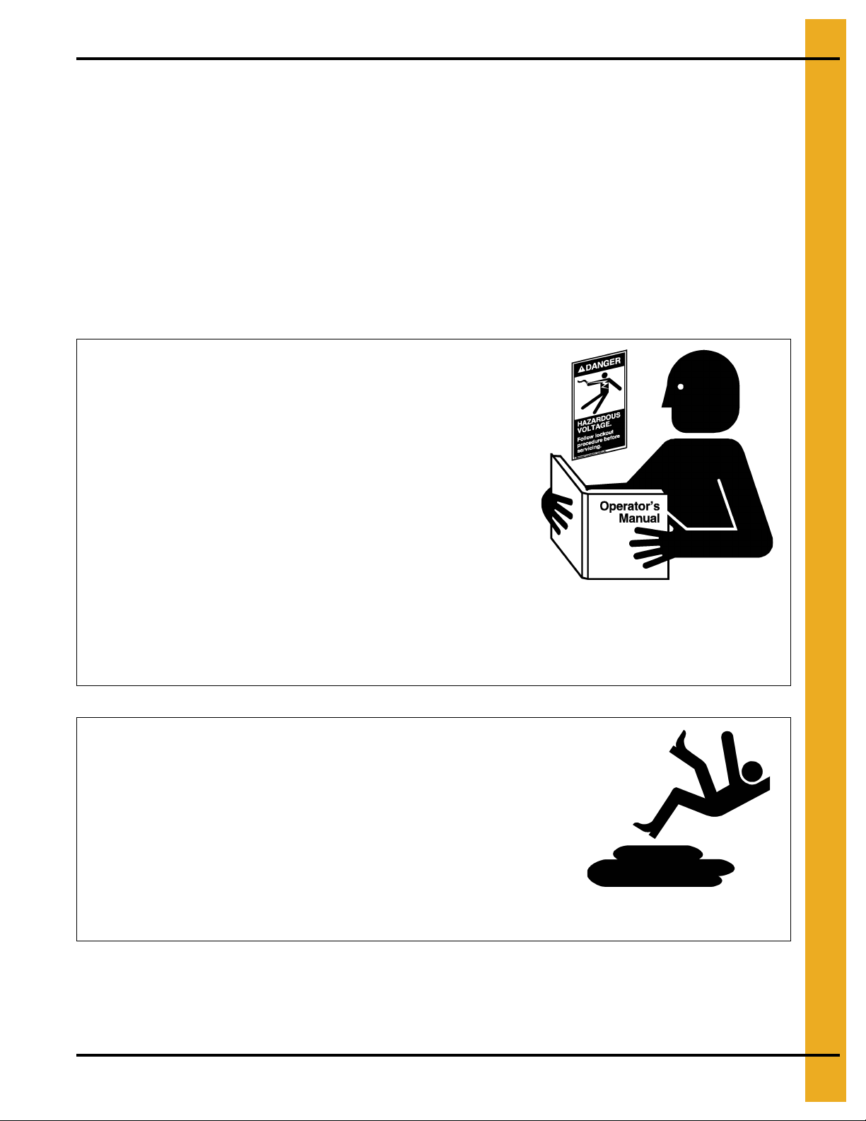
Follow Safety Instructions
Carefully read all safety messages in this manual and
safety signs on your machine. Keep signs in good
condition. Replace missing or damaged safety signs. Be
sure new equipment components and repair parts include
the current safety signs. Replacement safety signs are
available from the manufacturer.
Learn how to operate the machine and how to use controls
properly. Do not let anyone operate without instruction.
Keep your machinery in proper working condition.
Unauthorized modifications to the machine may impair
the function and/or safety and affect machine life.
If you do not understand any part of this manual or need
assistance, contact your dealer.
Read and Understand Manual
Practice Safe Maintenance
Understand service procedures before doing work. Keep area
clean and dry.
Never lubricate, service, or adjust machine while it is in operation.
Keep hands, feet, and clothing away from rotating parts.
Keep all parts in good condition and properly installed. Fix
damage immediately . Replace worn or broken p arts. Remove any
built-up grease, oil, and debris.
Maintain Equipment
and Work Area
Safety Instructions
Our foremost concern is your safety and the safety of others associated with this equipment. We want to
keep you as a customer. This manual is to help you understand safe operating procedures and some
problems that may be encountered by the operator and other personnel.
As owner and/or operator, it is your responsibility to know what requirements, hazards, and precautions
exist, and to inform all personnel associated with the equipment or in the area. Safety precautions may be
required from the personnel. Avoid any alterations to the equipment. Such alterations may produce a very
dangerous situation where SERIOUS INJURY or DEATH may occur.
This equipment shall be installed in accordance with the current installation codes and applicable
regulations, which should be carefully followed in all cases. Authorities having jurisdiction should be
consulted before installations are made.
PNEG-1095 FCDL 4.00" Corrugation Externally S tiffened Grain Bin 7
Page 8
2. Safety
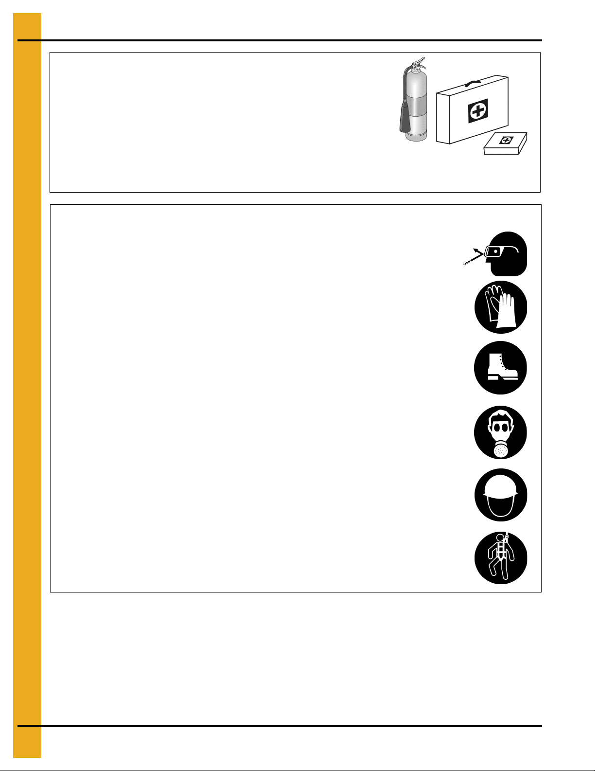
Prepare for Emergencies
Be prepared if fire starts.
Keep a first aid kit and fire extinguisher handy.
Keep emergency numbers for doctors, ambulance service,
hospital, and fire department near your telephone.
Keep Emergency Equipment
Quickly Accessible
Wear Protective Clothing
Wear close-fitting clothing and safety equipment appropriate
to the job.
Remove all jewelry.
Tie long hair up and back.
Wear safety glasses at all times to protect eyes from debris.
Wear gloves to protect your hands from sharp edges on plastic
or steel parts.
Wear steel-toed boots to help protect your feet from falling
debris. Tuck in any loose or dangling shoestrings.
A respirator may be needed to prevent breathing potentially
toxic fumes and dust.
Wear a hard hat to help protect your head.
Wear appropriate fall protection equipment when working at
elevations greater than six feet (6').
Eye Protection
Gloves
Steel-Toed Boots
Respirator
Hard Hat
Fall Protection
8 PNEG-1095 FCDL 4.00" Corrugation Externally Stiffened Grain Bin
Page 9
2. Safety
Safety Sign-Off Sheet
As a requirement of O.S.H.A., it is necessary for the employer to train the employee in the safe operating
and safety procedures for this auger. This sign-off sheet is provided for your convenience and personal
record keeping. All unqualified persons are to stay out of the work area at all times. It is strongly
recommended that another qualified person who knows the shut down procedure be in the area in the
event of an emergency.
Date Employee Name Supervisor Name
PNEG-1095 FCDL 4.00" Corrugation Externally S tiffened Grain Bin 9
Page 10

2. Safety
Proper Storage of Grain Bin/Silo Materials Prior to Construction
Wet storage stain (rust) will develop when closely packed bundles of galvanized material, such as sidewall
and roof sheets, have moisture present. Inspect roof and sidewall bundles on arrival for any moisture. If
moisture is present, it must not be allowed to remain between the she ets. Separate the sheets or panels
immediately and wipe them down. Spray with a light oil or diesel fuel.
If possible, sidewall bundles, roof sheets and other closely packed galvanized materials should be stored
in a dry, climate controlled building. If outdoor storage is unavoidable, the materials should be stored so
that they are raised above the ground and vegetation. Any stacking an d spacing mat erials sho uld not be
corrosive or wet. Be sure to protect materials from the weather, but permit air movement around the
bundles if possible.
Storing roof bundles and sidewall sheets at a slight incline can also help minimize the presence of
moisture. Storing the bundles with the center of the dome up (like an arch) is one option for minimizing
moisture during storage. Sidewall bundles can also be stored on edge but must be secured so that they
do not fall over and cause injury.
If “white rust” or “wet storage stain” occurs, contact the manufacturer imme diately about ways to minimize
the adverse effect upon the galvanized coating.
10 PNEG-1095 FCDL 4.00" Corrugation Externally Stiffened Grain Bin
Page 11
3. Decals
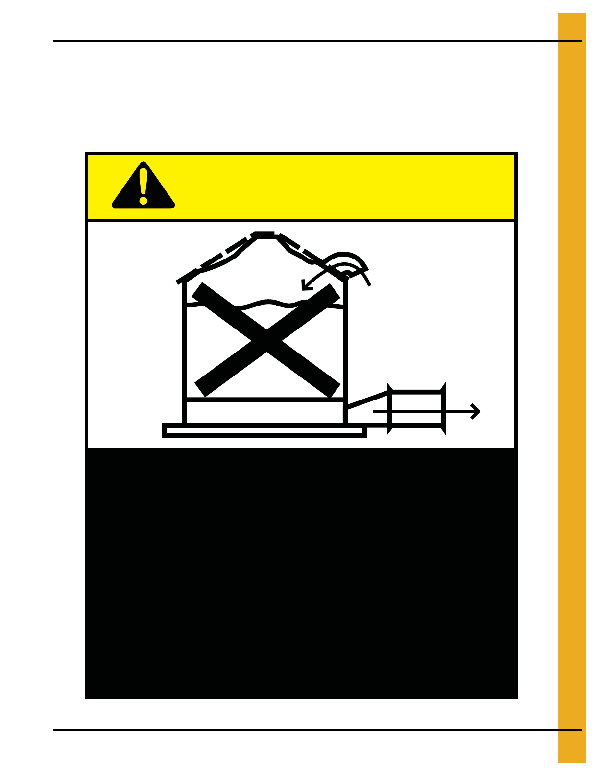
Excessive vacuum (or pressure) may
damage roof. Use positive aeration
system. Make sure all roof vents are
open and unobstructed. Start roof
fans when supply fans are started.
Do not operate when conditions exist
that may cause roof vent icing.
DC-969
CAUTION!
The manufacturer does not warrant any roof damage caused by excessive vacuum or internal
pressure from fans or other air moving systems. Adequate ventilation and/or “makeup air” devices
should be provided for all powered air handling systems. The manufacturer does n ot recommend
the use of downward flow systems (suction). Severe roof damage can result fro m any blockage of
air passages. Running fans during high humidity/cold weather conditions can cause air exhaust
or intake ports to freeze.
PNEG-1095 FCDL 4.00" Corrugation Externally S tiffened Grain Bin 11
Page 12
3. Decals
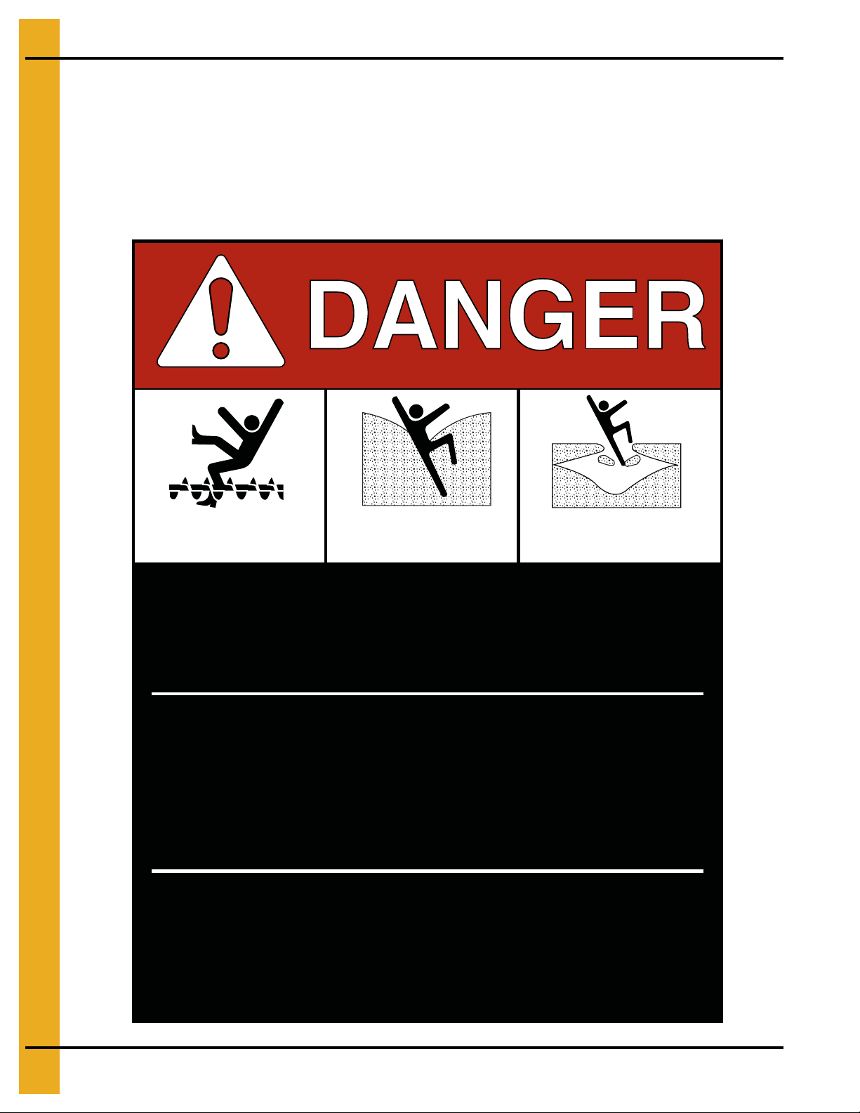
Rotating flighting will
kill or dismember.
Flowing material will
trap and suffocate.
Crusted material will
collapse and suffocate.
Keep clear of all augers.
DO NOT ENTER this bin!
Failure to heed these
warnings will result in
serious injury or death.
If you must enter the bin:
1. Shut off and lock out all power.
2. Use a safety harness and safety line.
3. Station another person outside the bin.
4. Avoid the center of the bin.
5. Wear proper breathing equipment or respirator.
DC-GBC-1A
ATTENTION: The decal shown below should be present on the outside of the door cover of the 2 ring,
24" porthole door cover and roof manway cover. If a decal has been damaged or is missing in any of these
locations, contact the manufacturer for a free replacement decal.
GSI Decals
1004 E. Illinois St.
Assumption, IL. 62510
Phone: 1-217-226-4421
12 PNEG-1095 FCDL 4.00" Corrugation Externally Stiffened Grain Bin
Page 13
3. Decals
ATTENTION: The decal shown below should be present on the outside of the door cover of the 2 ring,
24" porthole door cover and roof manway cover. If a decal has been damaged or is missing in any of these
locations, contact the manufacturer for a free replacement decal.
GSI Decals
1004 E. Illinois St.
Assumption, IL. 62510
Phone: 1-217-226-4421
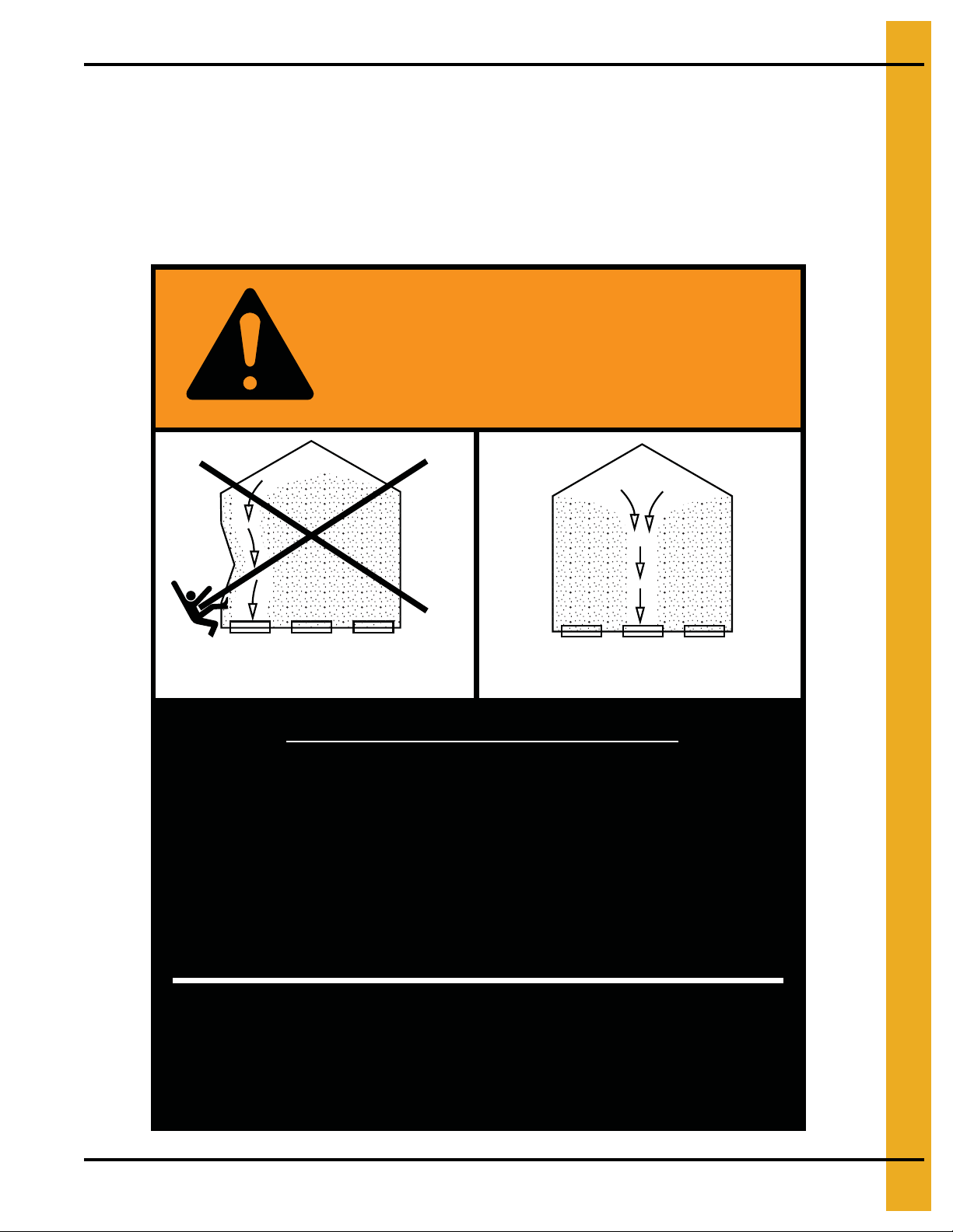
WARNING
DON’T
DO
UNLOADING INSTRUCTIONS:
1. Use CENTER FLOOR OUTLET ONLY until NO grain
remains above this outlet.
2. Side floor outlets to be used ONLY when above
condition is satisfied.
3. Lock all side floor outlets to avoid accidental
premature use.
4. See manufacturers instructions for proper use of
factory supplied sidedraw (wall) discharge systems.
Failure to heed these warnings
could result in serious injury, death,
structural damage or collapse of tank.
DC-GBC-2A
PNEG-1095 FCDL 4.00" Corrugation Externally S tiffened Grain Bin 13
Page 14
4. Storage and Drying Bins
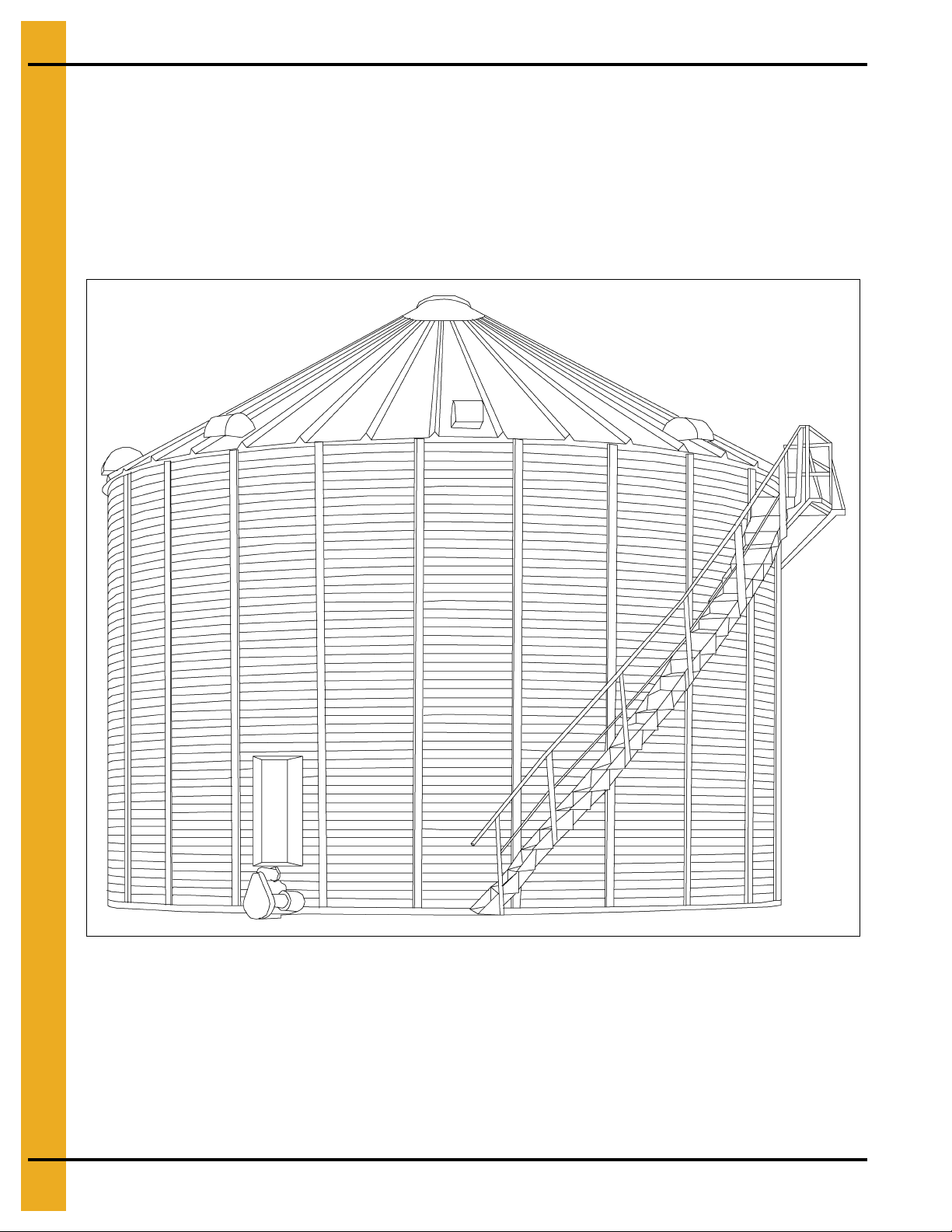
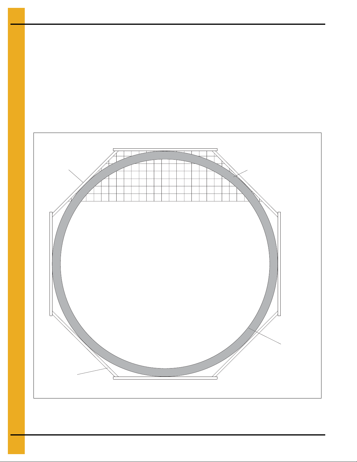
FCDL Bins
Drying bins up to 7 rings are designed for general drying and storage of small grains. Bins 8 rings and
taller are warranted for storage/aeration only - not drying. FCDL drying bins may be used with drying
equipment and most multi-screw stirring devices. In FCDL Bins with a standard walk-through door, the
door will be located in the second ring and top half of the bottom ring. FCDL bins are st andardly punched
for 12" plenum and stiffened to the eave. FCDL drying bins include the following: base angle, sidewall
sheets, door decal sheet, outside stiffeners, sidewall hardware with caulk, 30° roof, roof steps and one
manhole. For larger stirring devices or re-circulation units, consult with the engineering department.
Figure 4A
14 PNEG-1095 FCDL 4.00" Corrugation Externally Stiffened Grain Bin
Page 15
4. Storage and Drying Bins
WARNING
Stirring devices may create additional loads on grain bin sidewalls, roofs and
floors. If high-moisture grain is loaded too deep and too fast, bin walls can
become overloaded. Observe the following installation and operation procedures
if the bin is to be equipped with a stirring device.
Bins with Stirring Devices
Selecting the Appropriate “Series” Grain Bin
Grain storage tanks are offered in more than one structural series for specific uses. To maintain the
warranty, the appropriate “series” grain bin must be used. Consult the sales catalog or contact the
engineering department for current recommendations. Note that the use of any stirring device with
three (3) or more vertical screws may require a heavier than “standard” series bin. Any re-circulating
device or systems should be used in the “re-circulating” series bins. Re-circulating devices include
products such as the grain flow, foreway, shivers units or similar devices.
General Instructions for Stirring Devices
Bins are offered in more than one structural series for specific uses. In order to maintain warranty, the
appropriate “series” grain bin must be used. Consult the sales catalog or contact the engineering
department for current recommendations. Especially note that use of any stirring device with three (3) or
more vertical screws may require a heavier than “standard” series bin. Any re-circulating device or system
should be used in the “re-circulating” series bins.
NOTE: Additional loads on grain bin sidewalls, roofs and floors can be created by stirring devices. If
high-moisture grain is loaded too deep and too fast, any unstiffened bin wall can be overloaded.
Observe the following installation and operation procedures if the bin is to be equipped with the
stirring device.
1. Read the Owner’s manual for the stirring device and follow all instructions set forth by
the manufacture r.
IMPORTANT: Install the switch for t he stirring device near the roof manway opening so that the unit
can be observed while stirring.
2. Make sure there are no obstructions, such as protruding ladders.
3. After loading approximately three feet (3') of grain, run the unit for one complete revolution to
determine if it is working properly.
4. If the unit is functioning properly, operate the stirring device continuously while filling and drying to
avoid compacted grain around the vertical screws.
5. If it becomes necessary to stop the stirring device using laterally moving screws, try to stop it with the
vertical screws nearest to the center of the bin, away from the sidewall. Should a device stop or stall
for any reason and remain inoperable for any length of time, the auger carriage should be supported
to the grain surface before restarting. The vertical auger should be turned by hand, with a pipe
wrench, before the power is applied.
6. For best results, fill the bin to one-half of the final intended depth. Dry grain to 16% and continue
filling. Use filling rates specified by stirring device manufacturer. If necessary to fill to the top without
stopping, reduce the filling rate and drying air temperature so that the stirring rate can kee p up with
the drying rate.
7. Do not overfill bin. Filling should be stopped at the bottom of the top ring or 30" below the track.
8. The preceding steps are only general instructions which apply to the majority of stirring devices.
Since there are different manufacturers of these devices, it is important to read the Operator’s
manual thoroughly for specific instructions applicable to the machine.
PNEG-1095 FCDL 4.00" Corrugation Externally S tiffened Grain Bin 15
Page 16
5. Foundations
Foundation Recommendations
These are general foundation recommendations. Site conditions, system requirements and other factors
may create foundation construction requirements not covered by this manual.
Selecting the Proper Site Location
1. The selected site should be level, firm and free from underlying debris. The soil bearing capacity
should be equal to or greater than required by the footing specifications.
2. The concrete foundation surface must be level. If fill is required, it should be watered and tamped
thoroughly to prevent uneven settling from the weight of the bin.
3. The site should allow easy access for easy loading and unloading, as well as provide additional space
for future units.
4. When selecting a bin site, also consider the positioning of handling equipment, availability of
electricity and the placement of fans, heaters and gas tanks.
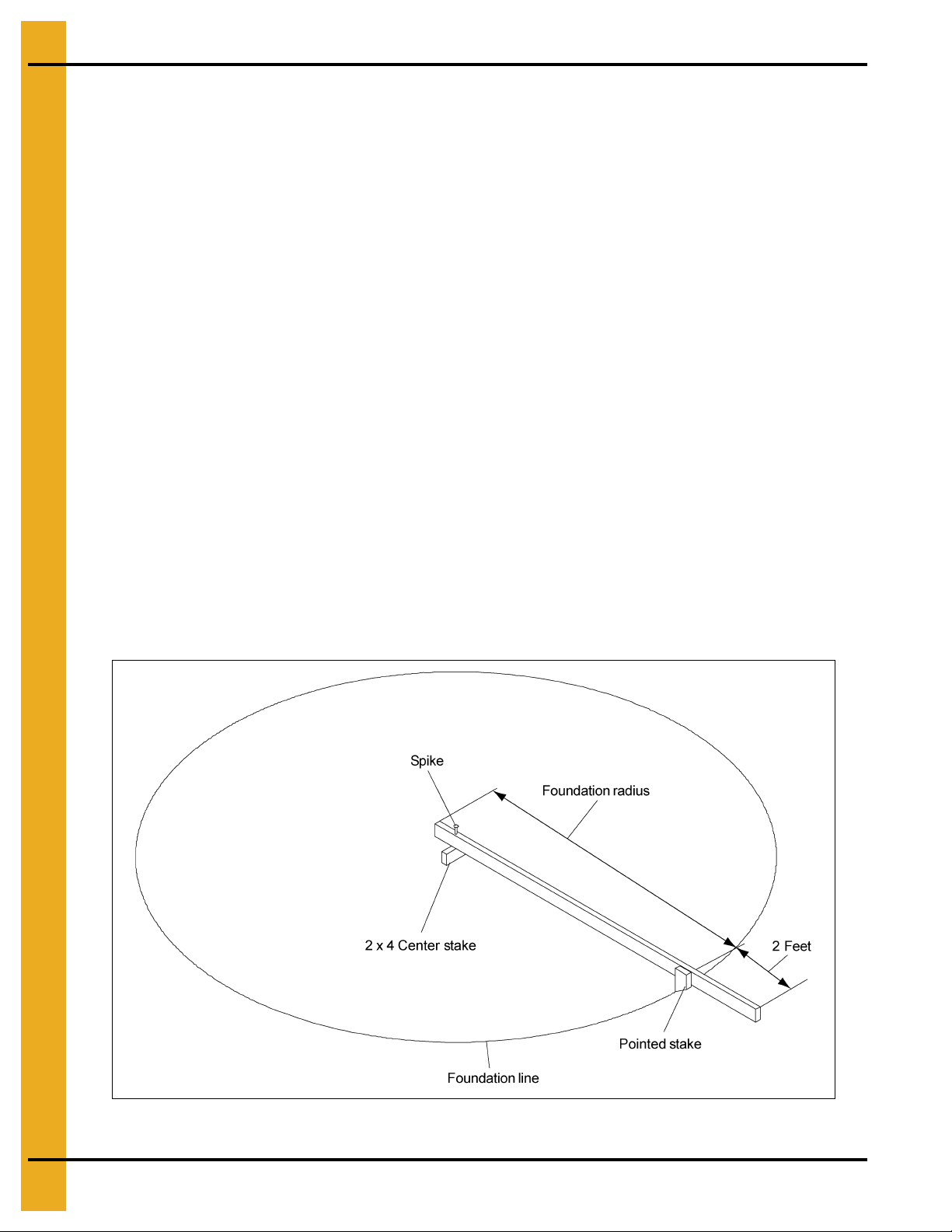
Scribe the Diameter
1. Determine the center of the foundation site and drive a small 2 x 4 in the ground to mark it. Drive
stake into the ground so that it is the same height as the finished foundation will be.
2. Using one large spike, nail a straight 2 x 4 to the top of the center spike. This 2 x 4 should be
approximately two feet (2') longer than the radius of the bin. The swiveling 2 x 4 will act as a compass,
enabling you to scribe the correct diameter of the foundation and later locate the anchor and stiffener
bolt locations.
NOTE: Making the 2 x 4 two feet (2') longer than the radius, allow the 2 x 4 to also be use d as a leveling
device and for pulling concrete.
Figure 5A Scribe the Diameter
16 PNEG-1095 FCDL 4.00" Corrugation Externally Stiffened Grain Bin
Page 17
5. Foundations
Foundation Forms
Foundation Form Options
Two (2) styles of foundation forms are commonly used for unstiffened farm bins. The first is the
Circular Form. (See Figure 5B.) The second style of foundation is the Octagon Form, made of
2" x 8" boards set into a square with blocked corners to form an octagon. This eight (8) sided form will
approximate a circle and is easy to construct. (See Figure 5C on Page 18.)
Figure 5B Circular Form
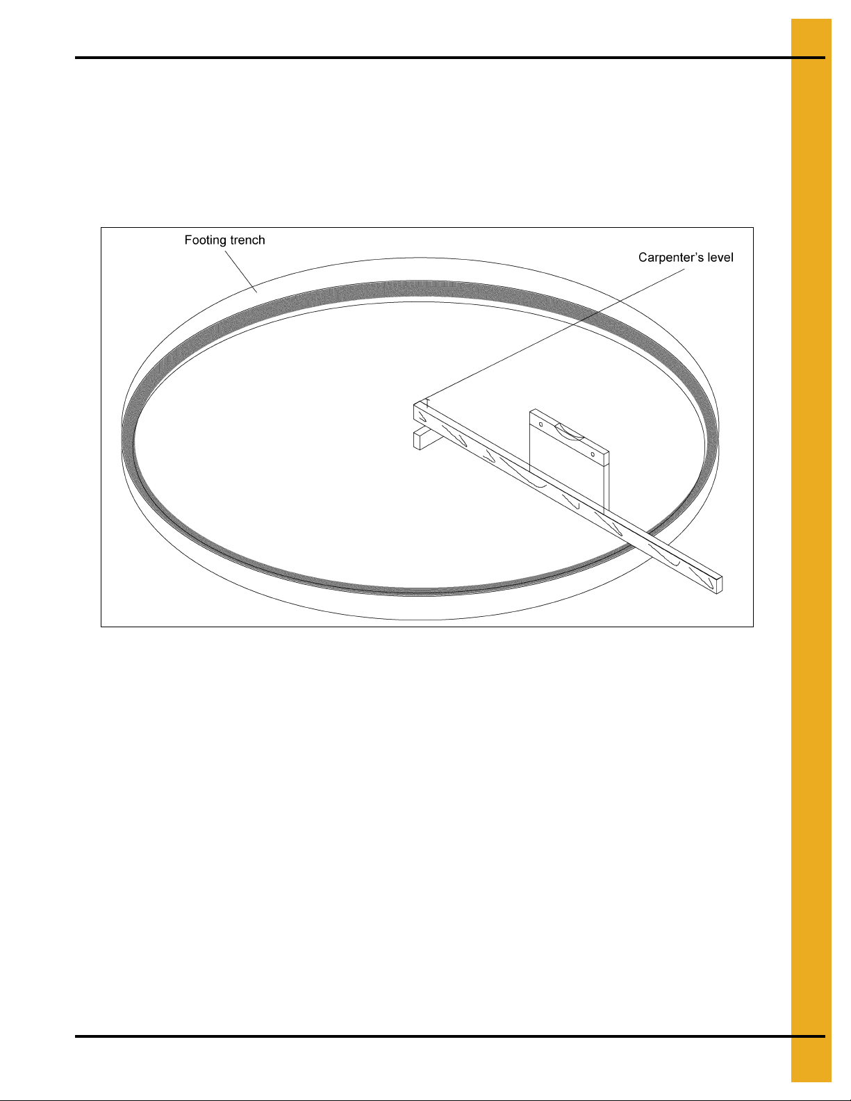
Preparing the Foundation Forms
1. Having scribed the diameter of the foundation, proceed by digging the foundation’s footing,
which consists of a large circular trench inside the foundation line. (Refer to foundation charts
on Pages 19-27.)
2. Once the footing has been dug, you are ready to build the forms. The forms must be rigid enough to
hold their shape against the poured concrete.
3. The foundation must be flat. Sloped floors cannot be used in drying bins. A carpenter’s level placed
on top of the compass 2 x 4 constructed earlier will enable you to set the top of the forms to match
the top of the center stake.
4. Check the form work with a transit to ensure a uniform elevation for the entire foundation. The
foundation should be level within 1/8" on non-stiffened tanks and within 1/4" on stiffened tanks at bin
wall perimeter. Stiffened tanks must be shimmed level. Provisions for unloading system trenches, air
ducts, etc., should be made as required by the particular grain system used.
NOTE: All foundation specifications shall be construed as recommendations only. Because of the many
variable conditions in actual installation, manufacturer assumes no liability for results arising from
the use of such recommendations.
PNEG-1095 FCDL 4.00" Corrugation Externally S tiffened Grain Bin 17
Page 18
5. Foundations
* All concrete to have a minimum
compressive strength of
3000 PSI at 28 days.
2" x 8" Forms
6" x 6" Wire mesh
Footing trench
Foundation line
Placing the Reinforcement
1. Once the forms and trench have been prepared, begin placing the reinforcement rods and mesh in
the foundation’s footing. (See the appropriate charts and drawings for the bin to determine
requirements and positions of the reinforcement on Pages 21-27.) Be sure reinforcement rods are
properly lapped by wiring.
2. Place at least 2" of compacted sand on the inside section of the foundation to provide a good base
for the concrete and to protect against rodents.
3. Cover the sand with 4 mil polyethylene plastic, which will act as a moisture barrier.
4. Add two (2) layers of 6" x 6" wire mesh to the entire area of the foundation slab or the entire
foundation for monolithic systems to complete the preparation of the bin’s foundation.
Figure 5C Octagon Form
18 PNEG-1095 FCDL 4.00" Corrugation Externally Stiffened Grain Bin
Page 19
5. Foundations
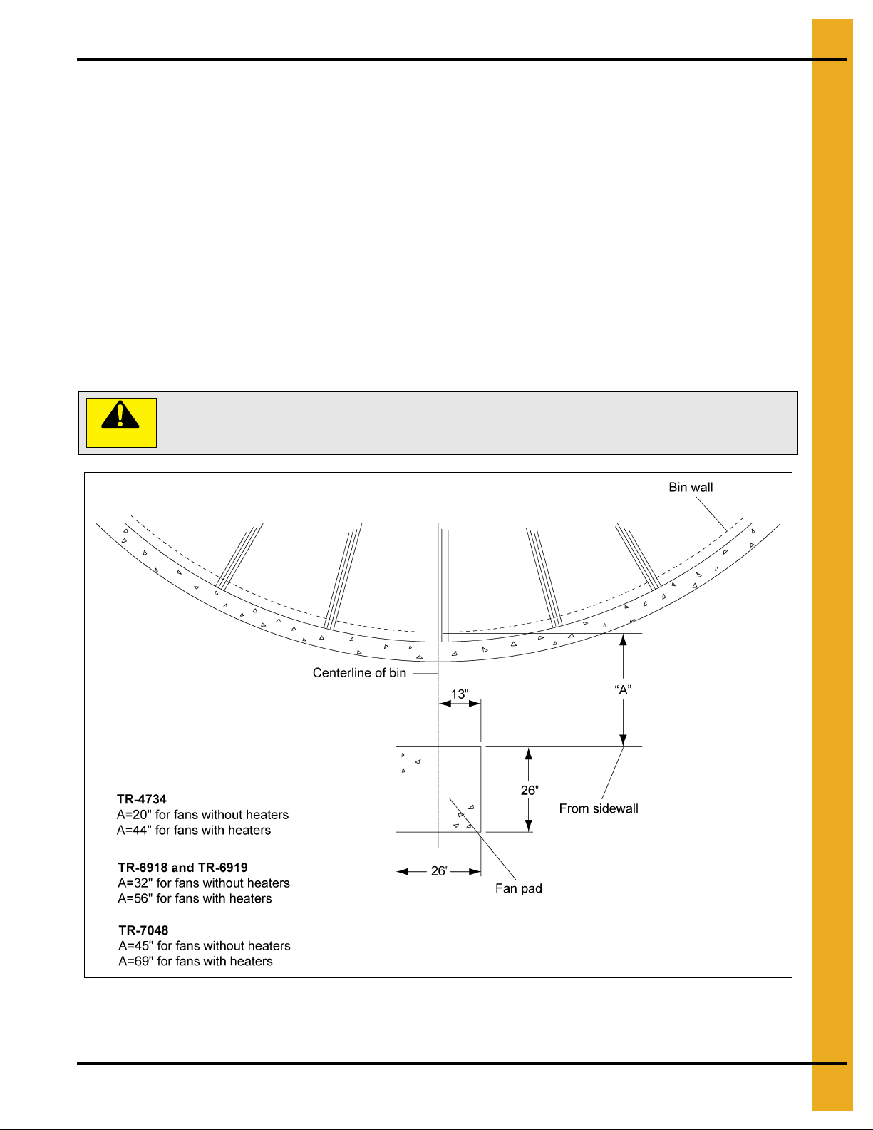
Fan pad and fan must be level and smooth for proper operation. Improper
leveling can cause vibration problems.
Placement of the Fan Pad: Tr ansitions, Fans and Heaters Only
Vane Axial Fan Pad
If a fan or fan and heater combination is to be installed, refer to Figure 5D below, to determine the concrete
pad size.
1. The top of this pad should be level with the top of the bin’s foundation.
2. Recommended pad thickness is 4" minimum.
3. Front of pad should be perpendicular to bin wall.
4. Pad for heater is not required. If it is to be added, pour the pad to cover the locations of both the heater
and the fan.
For fans and transitions used in aeration duct system applications, refer to the transition and aeration
installation instructions.
CAUTION
Figure 5D Vane Axial Fan Pad
PNEG-1095 FCDL 4.00" Corrugation Externally S tiffened Grain Bin 19
Page 20
5. Foundations
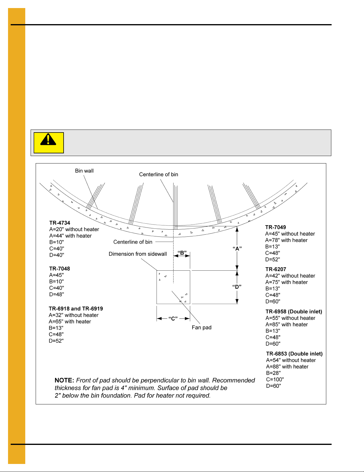
CAUTION
Fan pad and fan must be level and smooth for proper operation. Vibration
problems can result from improper fan leveling.
Centrifugal Fan Pad
1. Fan pad should be poured 2" below the top of bin foundation for all centrifugal fans.
2. A pad for heaters is not required, but is recommended.
3. Recommended pad thickness is four inches (4").
4. If a downwind heater pad is to be installed, the pad width (“C”) should be 48" and extended toward
the bin by 33".
5. Fan discharge should be centered on centerline of bin.
6. The fan pad should be perpendicular to bin wall.
Figure 5E Centrifugal Fan Pad
20 PNEG-1095 FCDL 4.00" Corrugation Externally Stiffened Grain Bin
Page 21
5. Foundations
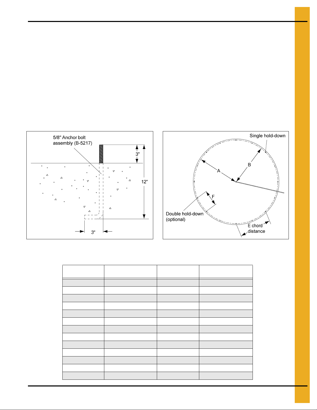
Anchor Bolt Placement
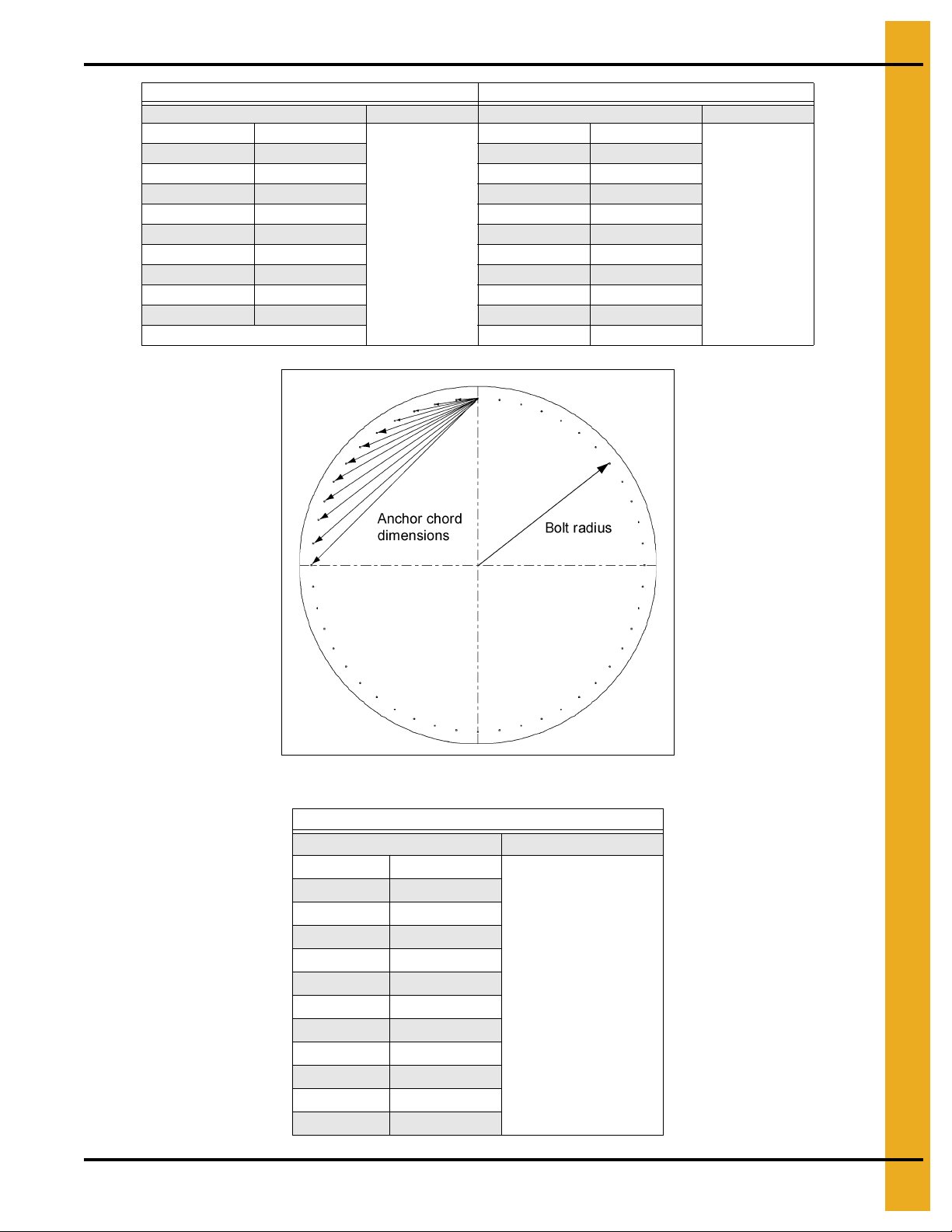
1. Having poured and leveled the concrete, use the center stake and straight 2 x 4 again to find the bolt
circle radius for the outside hold down brackets.
2. Select a starting point and stretch a pre-measured chord (“E” chord distance in Figure 5G) along the
imaginary circle formed by the bolt circle radius. This will give you the bolt locations on the bolt
circle radius.
3. Take into consideration the placement of these bolts so as not to interfere with the positions of bin
doors and transitions. (Refer to the following anchor bolt chart on Page 22 for necessary radius and
chord lengths.) Take the time and work carefully since accuracy is important.
NOTE: The top edge of slab where the bin wall sets must be held to within 1/8" of level.
NOTE: The above anchor bolt radii and dimensions are for the FCDL series only. For NC commercial
tanks, refer to the NC commercial section of the foundation recommendations in PNEG-318.
Figure 5F Anchor Bolt Detail (Typical) Figure 5G
Anchor Bolt Chart for FCDL Tank
Bin Diameter
12' 6' - 3-1/4'' 8 4' - 9-5/8''
15' 7' - 9-1/8'' 10 4' - 9-9/16''
18' 9' - 3-1/16'' 12 4' - 9-1/2''
21' 10' - 8-15/16'' 14 4' - 9-3/8''
24' 12' - 2-7/8'' 16 4' - 9-5/16''
27' 13' - 8-3/4'' 18 4' - 9-3/16''
30' 15' - 2-11/16'' 20 4' - 9-3/16''
33' 16' - 8-9/16'' 22 4' - 9-1/16''
36' 18' - 2-1/2'' 24 4' - 9-1/16''
42' 21' - 2-5/16'' 28 4' - 8-15/16''
48' 24' - 2-1/8'' 32 4' - 8-7/8''
54' 27' - 1-15/16'' 36 4' - 8-13/16''
60' 30' - 1-3/4'' 40 4' - 8-3/4''
PNEG-1095 FCDL 4.00" Corrugation Externally S tiffened Grain Bin 21
“B” Bolt Circle
Radius
# of Anchors “E” Chord Distance
Page 22
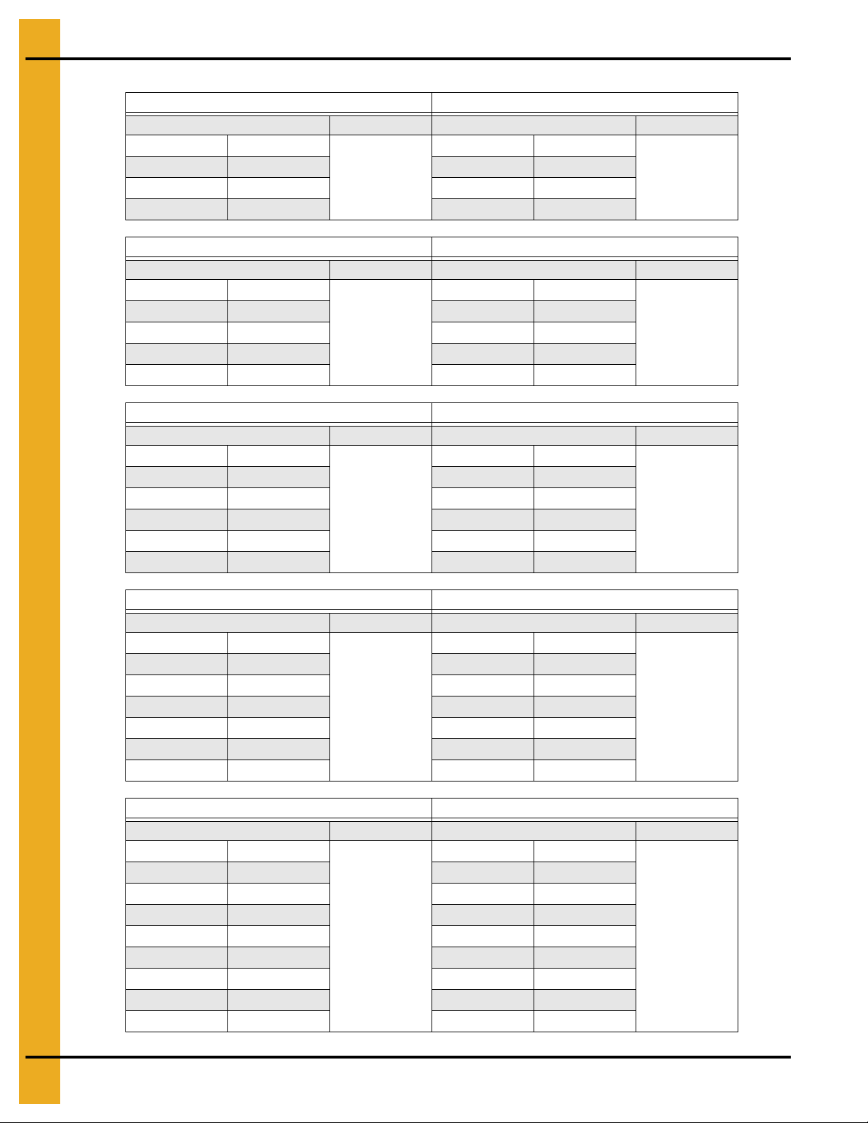
5. Foundations
Bolt Radius 6' - 3-1/4'' Bolt Qty. 8 Bolt Radius 7' - 9-1/8'' Bolt Qty. 10
Chord # Chord Dist. Chord # Chord Dist.
1 4' - 9-5/8'' 1 4' - 9-9/16''
2 8' - 10-7/16'' 2 9' - 1-1/2''
3 11' - 7-1/16" 3 12' - 6-11/16''
Bolt Radius 9' - 3-1/16'' Bolt Qty. 12 Bolt Radius 10' - 8-15/16" Bolt Qty. 14
Chord # Chord Dist. Chord # Chord Dist.
1 4' - 9-1/2" 1 4' - 9-3/8"
2 9'- 3-1/16" 2 9' - 3-7/8"
3 13' - 1-1/16" 3 13' - 4-13/16"
4 16'- 0-3/8" 4 16' - 9-5/8"
Bolt Radius 12' - 2-7/8'' Bolt Qty. 16 Bolt Radius 13' - 8-3/4" Bolt Qty. 18
Chord # Chord Dist. Chord # Chord Dist.
1 4' - 9-5/16" 1 4' - 9-3/16"
2 9' - 4-7/16" 2 9' - 4-11/16"
3 13' - 7-3/16" 3 13' - 8-3/4"
4 17' - 3-11/16" 4 17' - 7-13/16"
5 20' - 4-1/4" 5 21'-7/16"
Anchor Bolt Charts
12' Diameter Bin 15' Diameter Bin
18' Diameter Bin 21' Diameter Bin
24' Diameter Bin 27' Diameter Bin
30' Diameter Bin 33' Diameter Bin
Bolt Radius 15' - 2-11/16'' Bolt Qty. 20 Bolt Radius 16' - 8-9/16" Bolt Qty. 22
Chord # Chord Dist. Chord # Chord Dist.
1 4' - 9-3/16" 1 4' - 9-1/16"
2 9' - 4-15/16" 2 9'-5"
3 13' - 9-7/8" 3 13' - 10-5/8"
4 17' - 10-3/4" 4 18'-7/8"
5 21' - 6-3/8" 5 21' - 10-11/16"
6 24' - 7-5/8" 6 25' - 3-1/8"
36' Diameter Bin 42' Diameter Bin
Bolt Radius 18' - 2-1/2'' Bolt Qty. 24 Bolt Radius 21' - 2-5/16'' Bolt Qty. 28
Chord # Chord Dist. Chord # Chord Dist.
1 4' - 9-1/16" 1 4' - 8-15/16"
2 9' - 5-1/8" 2 9' - 5-3/16"
3 13' - 11-1/4" 3 14'-0"
4 18' - 2-1/2" 4 18' - 4-11/16"
5 22'-2" 5 22' - 6-5/8"
6 25'-9" 6 26' - 5-1/8"
7 28' - 10-11/16" 7 29' - 11-5/8"
8 31' - 6-7/16" 8 33' - 1-11/16"
22 PNEG-1095 FCDL 4.00" Corrugation Externally Stiffened Grain Bin
Page 23
5. Foundations
48' Diameter Bin 54' Diameter Bin
Bolt Radius 24' - 2-1/8'' Bolt Qty. 32 Bolt Radius 27' - 1-15/16'' Bolt Qty. 36
Chord # Chord Dist. Chord # Chord Dist.
1 4' - 8-7/8" 1 4' - 8-13/16"
2 9' - 5-3/16" 2 9' - 5-3/16"
3 14' - 7/16" 3 14' - 11/16"
4 18' - 6-1/16" 4 18' - 6-15/16"
5 22' - 9-1/2" 5 22' - 11-1/2"
6 26' - 10-3/8" 6 27' - 1-15/16"
7 30' - 8-1/8" 7 31' - 1-7/8"
8 34' - 2-5/16" 8 34'-11"
9 37' - 4-9/16" 9 38' - 4-15/16"
10 41' - 7-3/8"
Figure 5H
60' Diameter Bin
Bolt Radius 30' - 1-3/4" Bolt Qty. 40
Chord # Chord Dist.
1 4' - 8-3/4"
2 9' - 5-3/16"
3 14'-7/8"
4 18' - 7-9/16"
5 23'-7/8"
6 27' - 4-7/16"
7 31'-6"
8 35' - 5-1/4"
9 39' - 1-7/8"
10 42' - 7-9/16"
11 45' - 10-1/8"
PNEG-1095 FCDL 4.00" Corrugation Externally S tiffened Grain Bin 23
Page 24

5. Foundations
Floating Monolithic Foundation Pad for Bins with up to 5 Rings
Monolithic Pads
The foundation design is based on a minimum allowable soil bearing capacity of 3000 PSF. Bearing
capacity of the soils should be determined by geotechnical investigation and be of uniform
bearing capacity.
1. The foundation site must be free of vegetation and debris and be well drained.
2. The foundation must be founded below the frost line or placed on non expansive frost free fill.
3. All material used for backfill inside the ring wall should be clean, well graded, crushed rock or a sand
and gravel mixture. Backfill should be placed in 6" lifts, 95% compaction.
4. All reinforcement must meet the requirements of ASTM A615 grade 60 deformed bars.
5. Lap all circumferential bars 35 bar diameters and stagger all laps in plans 3'-0". Estimates do not
include end laps.
6. Concrete must have a minimum compressive strength of 3000 PSI at 28 days, 6%-8% air
entrainment, 4" slump.
Figure 5I Floating Monolithic Pad for Bins up to 5 Rings
* Contact the manufacturer’s engineering department for heights greater than 6".
** The optional #4 rebar grid can be substituted for the wire mesh in most cases. Place the #4 bars in the
pad at 18" c/c each way.
Bin
Diameter
12' 6'-9'' 6' - 3-1/4'' 4' - 9-5/8'' 8 4.5 300 100 200
15' 8'-3'' 7' - 9-1/8'' 4' - 9-9/16'' 10 6 500 100 300
18' 9'-9'' 9' - 3-1/16'' 4' - 9-1/2'' 12 8 700 200 400
21' 11'-3'' 10' - 8-15/16'' 4' - 9-3/8'' 14 10 900 200 600
24' 12'-9" 12' - 2-7/8'' 4' - 9-5/16'' 16 12.5 1100 200 700
27' 14'-3" 13' - 8-3/4'' 4' - 9-3/16'' 18 15 1200 200 900
30' 15'-9'' 15' - 2-11/16'' 4' - 9-3/16'' 20 18 1600 200 1100
33' 17'-3'' 16' - 8-9/16'' 4' - 9-1/16'' 22 21.5 1800 300 1300
36' 18'-9'' 18' - 2-1/2'' 4' - 9-1/16'' 24 25 2300 300 1500
Outside
Radius
Single Bolt
Radius
Anchor Chord # of Anchors
Total Cu. Yds.
Concrete
24 PNEG-1095 FCDL 4.00" Corrugation Externally Stiffened Grain Bin
Sq. Ft.
Mesh
Length #6
Bar
Optional #4
Grid (ft.)
Page 25

5. Foundations
Frost Free Pad Recommendations
Frost Free Pads
The foundation design is based on a minimum allowable soil bearing capacity of 3000 PSF. Bearing
capacity of the soils should be determined by geotechnical investigation and be of uniform
bearing capacity.
1. The foundation site must be free of vegetation and debris and well drained.
2. The foundation must be founded below the frost line or placed on non expansive frost free fill.
3. All material used for backfill inside the ring wall should be clean, well graded, crushed rock or a sand
and gravel mixture. Backfill should be placed in 6" lifts, 95% compaction.
4. All reinforcement must meet the requirements of ASTM A615 grade 60 deformed bars.
5. Lap all circumferential bars 35 bar diameters and stagger all laps in plans 3'-0". Estimates do not
include end laps.
6. Concrete must have a minimum compressive strength of 3000 PSI at 28 days, 6%-8% air
entrainment and 4" slump.
Figure 5J Frost Free Pad
* Contact the manufacturer’s engineering department for heights greater than 6".
** The optional #4 rebar grid can be substituted for the wire mesh in most cases. Place the #4 bars in the
pad at 18" c/c each way.
PNEG-1095 FCDL 4.00" Corrugation Externally S tiffened Grain Bin 25
Page 26

5. Foundations
Frost Free Pads
(Refer Figure 5J on Page 25.)
Diameter of Bin: 12'
Corrugation: 4.00"
Ring # B N
Outside
Radius
6 1 ft. 0 in. 2 6 ft. 9 in. 300 200 100 5
7, 8 1 ft. 7 in. 2 6 ft. 9 in. 300 200 100 5
9, 10 2 ft. 0 in. 2 7 ft. 0 in. 300 200 200 6
Diameter of Bin: 15'
Corrugation: 4.00''
Ring # B N
Outside
Radius
6 1 ft. 0 in. 2 8 ft. 3 in. 400 300 100 6
7, 8 1 ft. 7 in. 2 8 ft. 3 in. 400 300 100 7
9, 10 2 ft. 0 in. 2 8 ft. 7 in. 400 300 200 8
Diameter of Bin: 18'
Corrugation: 4.00''
Ring # B N
Outside
Radius
6 1 ft. 0 in. 2 9 ft. 9 in. 500 400 200 8
7, 8 1 ft. 7 in. 2 9 ft. 9 in. 500 400 200 9
9 2 ft. 0 in. 2 10 ft. 1 in. 500 400 200 11
Sq. Ft. Mesh
6 x 6 - 6/6
Sq. Ft. Mesh
6 x 6 - 6/6
Sq. Ft. Mesh
6 x 6 - 6/6
Optional #4**
18" x 18" Grid (ft.)
Optional #4**
18'' x 18'' Grid (ft.)
Optional #4**
18'' x 18'' Grid (ft.)
Length #6
Bar (ft.)
Length #6
Bar (ft.)
Length #6
Bar (ft.)
Total Cu. Yds.
Concrete
Total Cu. Yds.
Concrete
Total Cu. Yds.
Concrete
Diameter of Bin: 21'
Corrugation: 4.00''
Ring # B N
Outside
Radius
Sq. Ft. Mesh
6 x 6 - 6/6
Optional #4**
18'' x 18'' Grid (ft.)
Length #6
Bar (ft.)
Total Cu. Yds.
Concrete
6 1 ft. 1 in. 2 11 ft. 3 in. 700 500 200 11
7, 8 1 ft. 7 in. 2 11 ft. 3 in. 700 500 200 12
9 2 ft. 0 in. 2 11 ft. 6 in. 700 500 300 13
Diameter of Bin: 24'
Corrugation: 4.00''
Ring # B N
Outside
Radius
Sq. Ft. Mesh
6 x 6 - 6/6
Optional #4**
18'' x 18'' Grid (ft.)
Length #6
Bar (ft.)
Total Cu. Yds.
6 1 ft. 1 in. 2 12 ft. 9 in. 900 600 200 13
7, 8 1 ft. 9 in. 2 12 ft. 9 in. 900 600 200 15
9, 10 2 ft. 6 in. 3 13 ft. 2 in. 900 600 400 18
Diameter of Bin: 27'
Corrugation: 4.00''
Ring # B N
Outside
Radius
Sq. Ft. Mesh
6 x 6 - 6/6
Optional #4**
18'' x 18'' Grid (ft.)
Length #6
Bar (ft.)
Total Cu. Yds.
Concrete
6 1 ft. 2 in. 2 14 ft. 3 in. 1100 800 200 16
7, 8 1 ft. 10 in. 2 14 ft. 4 in. 1100 800 200 18
9, 10 2 ft. 7 in. 3 14 ft. 7 in. 1100 800 500 21
Diameter of Bin: 30'
Corrugation: 4.00"
Ring # B N
Outside
Radius
Sq. Ft. Mesh
6 x 6 - 6/6
Optional #4**
18" x 18" Grid (ft.)
Length #6
Bar (ft.)
Total Cu. Yds.
Concrete
6 1 ft. 2 in. 2 15 ft. 9 in. 1400 900 200 19
7, 8 1 ft. 10 in. 2 15 ft. 10 in. 1400 900 200 21
9, 10 2 ft. 8 in. 3 16 ft. 1 in. 1400 900 500 25
11, 12 3 ft. 8 in. 4 16 ft. 5 in. 1400 900 700 29
Concrete
26 PNEG-1095 FCDL 4.00" Corrugation Externally Stiffened Grain Bin
Page 27

5. Foundations
Diameter of Bin: 33'
Corrugation: 4.00"
Ring # B N
Outside
Radius
6 1 ft. 3 in. 2 17 ft. 3 in. 1700 1100 300 23
7, 8 1 ft. 11 in. 2 17 ft. 4 in. 1700 1100 300 25
9, 10 2 ft. 9 in. 3 17 ft. 6 in. 1700 1100 600 29
11, 12 3 ft. 10 in. 4 18 ft. 0 in. 1700 1100 800 34
Diameter of Bin: 36'
Corrugation: 4.00"
Ring # B N
Outside
Radius
6 1 ft. 3 in. 2 18 ft. 9 in. 2000 1300 300 26
7, 8 2 ft. 0 in. 2 18 ft. 11 in. 2000 1300 400 30
9, 10 2 ft. 10 in. 3 19 ft. 0 in. 2000 1300 600 33
11, 12 3 ft. 11 in. 4 19 ft. 6 in. 2000 1300 900 39
13 4 ft. 10 in. 5 19 ft. 9 in. 2000 1300 1100 43
Diameter of Bin: 42'
Corrugation: 4.00"
Ring # B N
Outside
Radius
6 1 ft. 4 in. 2 21 ft. 8 in. 2600 1800 300 34
7, 8 2 ft. 1 in. 3 21 ft. 11 in. 2600 1800 700 39
9 3 ft. 1 in. 4 22 ft. 2 in. 2600 1800 900 44
10, 11 4 ft. 2 in. 5 22 ft. 7 in. 2600 1800 1200 50
12, 13 4 ft. 10 in. 5 22 ft. 11 in. 2600 1800 1300 54
14 5 ft. 6 in. 6 23 ft. 2 in. 2600 1800 1500 66
Sq. Ft. Mesh
6 x 6 - 6/6
Sq. Ft. Mesh
6 x 6 - 6/6
Sq. Ft. Mesh
6 x 6 - 6/6
Optional #4**
18" x 18" Grid (ft.)
Optional #4**
18" x 18" Grid (ft.)
Optional #4**
18" x 18" Grid (ft.)
Length #6
Bar (ft.)
Length #6
Bar (ft.)
Length #6
Bar (ft.)
Total Cu. Yds.
Concrete
Total Cu. Yds.
Concrete
Total Cu. Yds.
Concrete
Diameter of Bin: 48'
Corrugation: 4.00"
Ring # B N
Outside
Radius
Sq. Ft. Mesh
6 x 6 - 6/6
Optional #4**
18" x 18" Grid (ft.)
Length #6
Bar (ft.)
Total Cu. Yds.
Concrete
6 1 ft. 5 in. 2 24 ft. 8 in. 3400 2300 400 44
7, 8 2 ft. 3 in. 3 24 ft. 11 in. 3400 2300 800 49
9 3 ft. 3 in. 4 25 ft. 2 in. 3400 2300 1100 55
10, 11 4 ft. 5 in. 5 25 ft. 8 in. 3400 2300 1400 63
12, 13 5 ft. 1 in. 5 25 ft. 11 in. 3400 2300 1500 67
14 5 ft. 8 in. 6 26 ft. 2 in. 3400 2300 1700 72
Diameter of Bin: 54'
Corrugation: 4.00"
Ring # B N
Outside
Radius
Sq. Ft. Mesh
6 x 6 - 6/6
Optional #4**
18" x 18" Grid (ft.)
Length #6
Bar (ft.)
Total Cu. Yds.
Concrete
6 1 ft. 5 in. 2 27 ft. 9 in. 4800 3300 400 56
7, 8 2 ft. 3 in. 3 28 ft. 1 in. 4800 3300 600 63
9, 10 3 ft. 3 in. 4 28 ft. 4 in. 4800 3300 700 69
11, 12 4 ft. 5 in. 5 28 ft. 7 in. 4800 3300 1400 75
13, 14 6 ft. 0 in. 6 29 ft. 2 in. 4800 3300 1900 87
Diameter of Bin: 60'
Corrugation: 4.00"
Ring # B N
Outside
Radius
Sq. Ft. Mesh
6 x 6 - 6/6
Optional #4**
18" x 18" Grid (ft.)
Length #6
Bar (ft.)
Total Cu. Yds.
Concrete
6 1 ft. 6 in. 2 30 ft. 7 in. 5400 3600 400 65
7, 8 2 ft. 10 in. 3 31 ft. 3 in. 5400 3600 1100 77
9, 10 3 ft. 8 in. 4 31 ft. 7 in. 5400 3600 1400 82
11, 12 4 ft. 7 in. 5 31 ft. 9 in. 5400 3600 1700 91
13 6 ft. 1 in. 6 32 ft. 4 in. 5400 3600 2200 103
PNEG-1095 FCDL 4.00" Corrugation Externally S tiffened Grain Bin 27
Page 28

5. Foundations
Inverted “T” Foundation (3000 PSF Soil Bearing Capacity)
Instructions
1. Determine bearing capacity of soils by using geotech nical investigations. Found all footings on soils
of uniform bearing capacity.
2. All bins with a diameter of 60' or larger must use ASTM A615 grade 60 deformed bars for concrete
reinforcement. Bins with a diameter less than 60' must use ASTM A615 grade 40 deformed bars.
3. Concrete must have a minimum compressive strength of 3000 PSI at 28 days.
4. Foundation site should be free of vegetation and debris and be well drained.
5. The foundation should be founded below the frost line or founded on non-frost susceptible soils.
6. Lap all circumferential bars 35 bar diameters and stagger all laps in plan 3' 0".
7. All material used for backfill inside the ring wall should be a clean, well graded, crushed stone or a
sandgravel mixture. Backfill should be placed in 6" lifts and well compacted.
8. Estimates do not include end laps.
Figure 5K Inverted “T” Foundation
28 PNEG-1095 FCDL 4.00" Corrugation Externally Stiffened Grain Bin
Page 29

5. Foundations
Inverted “T” Foundations
(See Figure 5K on Page 28.)
Diameter of Bin: 18'
Ring # B C D M N P #4 Bar (ft.) #5 Bar (ft.)
6 1'-3" 9'-8" 9'-8" 5 #4's 2 #5's #5 at 14" c/c 1600 300 18
7, 8 1'-7" 9'-8" 9'-10" 5 #4's 2 #5's #5 at 14" c/c 1600 300 19
9, 10 2'-2" 9'-8" 10'-1" 5 #4's 3 #5's #5 at 14" c/c 1600 300 20
11, 12 2'-4" 9'-8" 10'-2" 5 #4's 3 #5's #5 at 14" c/c 1600 300 21
Diameter of Bin: 21'
Ring # B C D M N P #4 Bar (ft.) #5 Bar (ft.)
6 1'-3" 11'-2" 11'-2" 5 #4's 2 #5's #5 at 14" c/c 2000 300 22
7, 8 1'-8" 11'-2" 11'-4" 5 #4's 2 #5's #5 at 14" c/c 2000 300 23
9, 10 2'-3" 11'-2" 11'-7" 5 #4's 3 #5's #5 at 14" c/c 2000 400 25
11, 12 2'-6" 11'-2" 11'-8" 5 #4's 3 #5's #5 at 14" c/c 2000 400 27
Diameter of Bin: 24'
Ring # B C D M N P #4 Bar (ft.) #5 Bar (ft.)
6 1'-3" 12'-8" 12'-8" 5 #4's 2 #5's #5 at 14" c/c 2300 300 26
7, 8 1'-9" 12'-8" 13'-1" 5 #4's 2 #5's #5 at 14" c/c 2300 300 27
9 2'-5" 12'-8" 13'-2" 5 #4's 3 #5's #5 at 14" c/c 2300 500 29
10, 11 2'-8" 12'-8" 13'-4" 5 #4's 3 #5's #5 at 14" c/c 2300 500 31
Cu. Yds.
Concrete
Cu. Yds.
Concrete
Cu. Yds.
Concrete
Diameter of Bin: 27'
Ring # B C D M N P #4 Bar (ft.) #5 Bar (ft.)
6 1'-3" 14'-2" 14'-2" 5 #4's 2 #5's #5 at 14" c/c 2600 300 31
7, 8 1'-10" 14'-2" 14'-5" 5 #4's 2 #5's #5 at 14" c/c 2600 400 33
9 2'-6" 14'-2" 14'-8" 5 #4's 3 #5's #5 at 14" c/c 2600 500 35
10, 11 3'-4" 14'-2" 15'-1" 5 #4's 4 #5's #5 at 14" c/c 2600 700 37
Diameter of Bin: 30'
Ring # B C D M N P #4 Bar (ft.) #5 Bar (ft.)
6 1'-3" 15'-8" 15'-8" 5 #4's 2 #5's #5 at 14" c/c 3000 300 36
7, 8 1'-11" 15'-8" 16'-0" 5 #4's 2 #5's #5 at 14" c/c 3000 400 39
9, 10 2'-7" 15'-8" 16'-3" 5 #4's 3 #5's #5 at 14" c/c 3000 500 42
11, 12 3'-6" 15'-8" 16'-10" 5 #4's 4 #5's #5 at 14" c/c 3000 700 44
13 3'-11" 15'-8" 17'-0" 5 #4's 4 #5's #5 at 14" c/c 3000 700 46
Diameter of Bin: 33'
Ring # B C D M N P #4 Bar (ft.) #5 Bar (ft.)
6 1'-4" 17'-1" 17'-1" 5 #4's 2 #5's #5 at 14" c/c 3400 400 40
7, 8 1'-11" 17'-1" 17'-4" 5 #4's 2 #5's #5 at 14" c/c 3400 500 42
9, 10 2'-8" 17'-1" 17'-8" 5 #4's 3 #5's #5 at 14" c/c 3400 600 45
11, 12 3'-8" 17'-1" 18'-2" 5 #4's 4 #5's #5 at 14" c/c 3400 800 48
13 4'-2" 17'-1" 18'-7" 5 #4's 4 #5's #5 at 14" c/c 3400 900 51
Cu. Yds.
Concrete
Cu. Yds.
Concrete
Cu. Yds.
Concrete
PNEG-1095 FCDL 4.00" Corrugation Externally S tiffened Grain Bin 29
Page 30

5. Foundations
Diameter of Bin: 36'
Ring # B C D M N P #4 Bar (ft.) #5 Bar (ft.)
6 1'-4" 18'-7" 18'-7" 5 #4's 2 #5 's #5 at 14" c/c 3800 400 44
7, 8 2'-0" 18'-7" 18'-11" 5 #4's 2 #5's #5 at 14" c/c 3800 500 47
9, 10 2'-10" 18'-7" 19'-3" 5 #4's 3 #5's #5 at 14" c/c 3800 700 50
11, 12 3'-9" 18'-7" 19'-8" 5 #4's 4 #5's #5 at 14" c/c 3800 1000 55
13 4'-4" 18'-7" 20'-3" 5 #4's 4 #5's #5 at 14" c/c 3800 1200 58
Diameter of Bin: 42'
Ring # B C D M N P #4 Bar (ft.) #5 Bar (ft.)
6 1'-5" 21'-7" 21'-8" 5 #4's 2 #5's #5 at 14" c/c 4700 500 56
7, 8 2'-2" 21'-7" 22'-0" 5 #4's 3 #5's #5 at 14" c/c 4700 600 60
9 3'-0" 21'-7" 22'-4" 5 #4's 3 #5's #5 at 14" c/c 4700 700 64
10, 11 4'-0" 21'-7" 22'-9" 5 #4's 4 #5's #5 at 14" c/c 4700 1000 69
12, 13 4'-6" 21'-7" 23'-3" 5 #4's 4 #5's #5 at 14" c/c 4700 1200 71
Diameter of Bin: 48'
Ring # B C D M N P #4 Bar (ft.) #5 Bar (ft.)
6 1'-6" 24'-7" 24'-8" 5 #4's 2 #5's #5 at 14" c/c 5600 600 68
7, 8 2'-3" 24'-7" 25'-0" 5 #4's 3 #5's #5 at 14" c/c 5600 800 72
9 3'-2" 24'-7" 25'-5" 6 #4's 3 #5's #5 at 14" c/c 5800 900 77
10, 11 4'-2" 24'-7" 25'-10" 6 #4's 4 #5's #5 at 14" c/c 5800 1200 84
12, 13 4'-10" 24'-7" 26'-5" 6 #4's 4 #5's #5 at 14" c/c 6300 1300 87
Cu. Yds.
Concrete
Cu. Yds.
Concrete
Cu. Yds.
Concrete
Diameter of Bin: 54'
Ring # B C D M N P #4 Bar (ft.) #5 Bar (ft.)
6 2'-0" 27'-7" 28'-1" 5 #4's 3 #5's #5 at 14" c/c 6600 900 85
7, 8 2'-9" 27'-7" 28'-4" 5 #4's 3 #5's #5 at 14" c/c 6600 1000 90
9, 10 3'-6" 27'-7" 28'-7" 5 #4's 4 #5's #5 at 14" c/c 6600 1200 94
11, 12 4'-3" 27'-7" 28'-10" 6 #4's 4 #5's #5 at 14" c/c 6900 1300 103
Diameter of Bin: 60'
Ring # B C D M N P #4 Bar (ft.) #5 Bar (ft.)
6 2'-0" 30'-9" 31'-3" 5 #4's 3 #5's #5 at 14" c/c 7700 900 101
7, 8 2'-10" 30'-9" 31'-6" 5 #4's 3 #5's #5 at 14" c/c 7700 1000 106
9, 10 3'-6" 30'-9" 31'-9" 5 #4's 4 #5's #5 at 14" c/c 7700 1300 111
11, 12 4'-5" 30'-9" 32'-2" 7 #4's 5 #5's #5 at 14" c/c 8500 1700 117
Cu. Yds.
Concrete
Cu. Yds.
Concrete
30 PNEG-1095 FCDL 4.00" Corrugation Externally Stiffened Grain Bin
Page 31

Hardware
CAUTION
Under no condition shall any other bolts be substituted for those supplied by
the manufacturer.
Grade 2 Bolts
1. Grade 2 bolts are designated with a plain head. Grade 2 bolts will not be used in this grain bin.
Grade 5 Bolts
2. Grade 5 bolts are designated by three (3) slash marks on the head. All 5/16" diameter bolts
are to be grade 5 or higher.
Grade 8 Bolts
3. Grade 8 bolts are designated by six (6) slash marks evenly spaced on the head.
Grade 8.2 Bolts
4. Grade 8.2 bolts are designated by six (6) slash marks on the head in a sunrise pattern.
All 3/8" diameter bolts are to be grade 8 or 8.2.
Identifying Bolt Grades
5. Foundations
NOTE: Do not tighten bolts to exceed the torque specifications listed below.
Bolt Size
5/16"-18 15 20
Hardware Usage
20 Gauge - 15 gauge sidewall sheets, use 5/16" x 3/4" bolts and nuts. (S-275) [44 pcs.]
14 Gauge sidewall sheets, use 5/16" x 3/4" bolts and nuts. (S-275) [66 pcs.]
3/8"-16 35 42
7/16"-14 65 72
1/2"-13 95 105
Minimum Maximum
Torque (ft. lbs.)
13 Gauge - 8 gauge sidewall sheets, use 3/8" x 1" bolts and nuts. (S-455) [66 pcs.]
Use 5/16" bolts and nuts when joining 13 gauge to 12 gauge on horizontal seams.
Use 5/16" x 1-1/4" (S-277) for attaching floor flashing to the sidewall.
PNEG-1095 FCDL 4.00" Corrugation Externally S tiffened Grain Bin 31
Page 32

5. Foundations
Bolting Requirements
New Style FCDL Stiffener Hardware Splice connections are figured for
Per Splice
16 Gauge 6 S-7927 3/8" x 1" Hex Flanged
Splice Bolting
6S-93733/8" Hex Nuts
(2 Stiffeners Per Sheet)
[(22) S-275 Per Sheet] 22 S-275 5/16" x 3/4" Bin Bolt
[(22) S-396 Per Sheet] 22 S-396 5/16" Hex Nuts
14 Gauge 8 S-7927 3/8" x 1" Hex Flanged
(2 Stiffeners Per Sheet) Per Sheet
[(22) S-275 Per Sheet] Stiffener to Sidewall Bolting 22 S-275 5/16" x 3/4" Bin Bolt
[(22) S-396 Per Sheet] 22 S-396 5/16" Hex Nuts
12 Gauge 8 S-7927 3/8" x 1" Hex Flanged
(2 Stiffeners Per Sheet) Per Sheet
[(22) S-275 Per Sheet] 20 S-275 5/16" x 3/4" Bin Bolt
[(2) S-277 Per Sheet] 2 S-277 5/16" x 1-1/4" Bin Bolt
[(22) S-396 Per Sheet] 22 S-396 5/16" Hex Nuts
Transitionals Splice connections are figured for
12 Gauge to 10 Gauge 8 S-7927 3/8" x 1" Hex Flanged
(2 Stiffeners Per Sheet)
[(20) S-275 Per Sheet] 20 S-275 5/16" x 3/4" Bin Bolt
[(2) S-277 Per Sheet] 2 S-277 5/16" x 1-1/4" Bin Bolt
[(22) S-396 Per Sheet] 22 S-396 5/16" Hex Nuts
10 Gauge Transitional to 8 Gauge 12 S-7927 3/8" x 1" Hex Flanged
8 Gauge to 8 Gauge Splice Bolting
Add (1) FC-42076 Per Connection Per Sheet
[(18) S-275 Per Sheet] 18 S-275 5/16" x 3/4" Bin Bolt
[(4) S-277 Per Sheet] 4 S-277 5/16" x 1-1/4" Bin Bolt
[(4) S-277 Per Sheet] 22 S-396 5/16" Hex Nuts
8 Gauge to 5 Gauge 12 S-7927 3/8" x 1" Hex Flanged
5 Gauge to 5 Gauge Bearing Splice Bolting
Add (1) FC-42076 Per Connection 12 S-9373 3/8" Hex Nuts
[(22) S-277 Per Sheet] Stiffener to Sidewall Bolting 22 S-277 5/16" x 1-1/4" Bin Bolt
5 Gauge Stiffener 22 S-396 5/16" Hex Nuts
New Style FCDL Sidewall Hardware ** Refer to Stiffener Sheets for Stiffener
20 Gauge to 15 Gauge
14 Gauge
11 Gauge to 13 Ga uge
Stiffener to Sidewall Bolting
Splice Bolting
Splice Bolting
Stiffener to Sidewall Bolting
Splice Bolting
Stiffener to Sidewall Bolting
Stiffener to Sidewall Bolting
56 S-275 5/16" x 3/4" Bin Bolt
56 S-396 5/16" Hex Nuts
7 ft. S-4458 Caulking (24' Roll)
68 S-275 5/16" x 3/4" Bin Bolt
68 S-396 5/16" Hex Nuts
7 ft. S-4458 Caulking (24' Roll)
68 S-455 3/8" x 1" Bin Bolt
68 S-456 3/8" Hex Nut
7 ft. S-4458 Caulking (24' Roll)
Per Sheet
Per Splice
8S-93733/8" Hex Nuts
Per Splice
8S-93733/8" Hex Nuts
Per Splice
8 S-9373 3/8" Hex Nuts
Per Sheet
Per Splice
12 S-9373 3/8" Hex Nuts
Per Splice
**For stiffener to sidewall quantities see stiffener hardware.
32 PNEG-1095 FCDL 4.00" Corrugation Externally Stiffened Grain Bin
Page 33

5. Foundations
Stiffener and Sidewall Seam Bolts
2 Stiffeners per Sidewall Sheet
Sidewall Gauge Horizontal Seam* Vertical Seam Stiffener to Sidewall** Overlap Seam
15 through 20 5/16" x 3/4" [10] 5/16" x 3/4" [42] 5/16" x 3/4" [20] 5/16" x 3/4" [2]
14 5/16" x 3/4" [22] 5/16" x 3/4" [42] 5/16" x 3/4" [20] 5/16" x 3/4" [2]
10 through 13 3/8" x 1" [22] 3/8" x 1" [42] 5/16" x 1-1/4" [20] 5/16" x 1-1/4" [2]
Seams
* At the horizontal seam between 14 gauge and 13 gauge, utilize 5/16" diameter bolts for the
horizontal seam.
** At the horizontal seam, the horizontal seam bolt will attach the stiffener and sidewall sheets.
A 5/16" diameter bolt may be used for this location only for 13 gauge and thicker sidewall sheets.
Figure 5L Standard Sheet Bolting Detail (Viewed from outside of the bin.)
Stiffeners
For splice plates FC-42076 and 12 gauge and their stiffener overlaps, use 5/16" x 1-1/4" bolts for
the stiffener to sidewall connections. 5 Gauge stiffeners will utilize 5/16" x 1-1/4" bolt for stiffener to
sidewall attachment.
Floor Flashing
Use 5/16" x 1-1/4" (S-277) for attaching floor flashing to the sidewall.
PNEG-1095 FCDL 4.00" Corrugation Externally S tiffened Grain Bin 33
Page 34

5. Foundations
0.3125" x 0.750" Bolt pre-assembled with a steel backed neoprene washer.
This bolt is used to connect horizontal and vertical seams for 14 gauge and thinner sidewall sheets
to each other and to bolt the stiffeners to the sidewall sheets. It is also used in att aching roof p anels
to the top sidewall sheet and attaching roof panels and flashing to the center collar.
S-275
0.3125" x 1.250" Bolt pre-assembled with a steel backed neoprene washer.
This bolt is primarily used to connect roof panels together where they overlap and is also used at the
bottom of the flat bottomed bins to attach the base angle to the sidewall sheet. This bolt is also
provided for overlap joints, FC-42076 splice plates for the stiffeners to sidewall connection and
stiffener to sidewall connections for 5 gauge stiffeners.
S-277
Bolt Usage
(Refer to Page 31 and Page 32 for complete bolt usage.)
34 PNEG-1095 FCDL 4.00" Corrugation Externally Stiffened Grain Bin
Page 35

5. Foundations
0.375" x 1.000" Hex flanged head without a plastic sealing washer.
This bolt is used to splice the stiffeners together on the flanges. A steel flat washer is used on the nut
side of the connection. They are also used on the roof rafter splices for commercial roof systems.
S-7927
0.375" x 1.000" Bolt pre-assembled with a steel backed neoprene washer.
This bolt is used in horizontal and vertical seams for 13 gauge through 10 gauge sidewall to attach
the sheets to each other. It is not used to splice the stiffeners together on the flanges where they
connect to each other or the splice plates.
S-455
NOTE: The only washers shipped loose with the bin sidewall hardware are the steel flat washers, which
are used for stiffener splices, base angle attachment locations and with some roof components.
Consult the specific component instructions for details on washer usage.
PNEG-1095 FCDL 4.00" Corrugation Externally S tiffened Grain Bin 35
Page 36

5. Foundations
Color Chart for Bin Hardware Bucket Lids
Part # Color Description
S-275 5/16" x 3/4" Bolt pre-assembled with a steel backed sealing washer
S-277 5/16" x 1-1/4" Bolt pre-assembled with a steel backed sealing washer
S-396 5/16" Hex nut
S-455 3/8" x 1" Bolt pre-assembled with a steel backed sealing washer
S-456 3/8" Hex nut
S-5060 3/8" x 1-1/2" Bolt pre-assembled with a steel backed sealing washer
S-7927 3/8" x 1" Hex flanged head bolt without
S-7928 3/8" x 1-1/2" Hex flanged head bolt without sealing washer
S-8479 7/16" Special recessed nuts
Dark Blue
Black
Red
Grey
Yellow
Orange
Light Green
Dark Brown
Light Brown
sealing washer
S-9373 3/8" Hex flanged nuts
S-9444 7/16" x 2-1/2" Bolt pre-assembled with a steel backed sealing washer
S-9445 3/8" x 2" Bolt pre-assembled with a steel backed sealing washer
S-9470 7/16 " x 2" Bolt pre-assembled with a steel backed sealing washer
Dark Purple
Dark Green
Light Blue
Light Purple
36 PNEG-1095 FCDL 4.00" Corrugation Externally Stiffened Grain Bin
Page 37

5. Foundations
Location of Accessories
1. On this page are typical bin layouts showing the suggested location of bin accessories. Figure 5M
below shows two (2) fans should be placed at a 90° angle to each other.
Figure 5M Placement with Two (2) Fans
2. Figure 5N below shows the fan and unloading auger on opposite sides of the bin to allow good air
flow. When locating the manway, be sure the ladder will not interfere with the other bin accessories
below it. Roof vents should be spaced evenly around the roof.
Figure 5N Placement with One Fan
PNEG-1095 FCDL 4.00" Corrugation Externally S tiffened Grain Bin 37
Page 38

6. Installation
Sidewall Construction
Sidewall Construction Instructions
Gauge Color Code
1. Before bolting the sidewall sheets together, check for the proper gauge of steel for the first ring.
Higher gauge numbers denote the thinner materials. (For example, 20 gauge material is thinner than
14 gauge.)
2. In erecting most grain bins, the thinnest material usually goes on top, therefore the first sidewall ring
you assemble will be the top ring of the bin.
3. Check the various gauges of the bin with the color code chart and begin building accordingly.
REMEMBER assemble the top ring first.
Gauge Color Code
20 Red
19 Black/Yellow
18 Orange
17 Pink/Light Blue
16 Blue
15 Brown/Red
14 Green
13 Yellow/Blue
12 Black
11 Pink
10 Light Blue
9 Blue/Orange
8 Yellow
Figure 6A
38 PNEG-1095 FCDL 4.00" Corrugation Externally Stiffened Grain Bin
Page 39

6. Installation
NOTE: The rope caulking is installed before each sheet is assembled. Apply rope caulking between the
last vertical row of bolts and edge of outside sheet. There is sufficient caulking for all vertical seams
on storage and drying bins. Wipe sheet clean where caulking is to be applied.
Figure 6B Standard Sidewall Sheets (As viewed from inside bin.)
Figure 6C Tighten Bolts in Order
PNEG-1095 FCDL 4.00" Corrugation Externally S tiffened Grain Bin 39
Page 40

6. Installation
Caulking and Bolting Sidewall Sheets
1. Install rope caulk to each sheet before it is assembled. (See Figure 6B on Page 39.)
2. Begin assembling sidewall sheets, end to end (overlapping the same way throu ghout), until the ring
is completed. Use correct size bin bolts throughout. All body sheet bolts are to be installed with the
bolt head and its neoprene washer to the outside and the nut on the inside. Do not tighten bolts until
all sheets are assembled and form a complete ring.
3. Attach lifting brackets to stiffener bolt holes. These straps, coupled to the jacks will enable you to later
elevate the bin.
4. Now tighten the bolts in sequence, starting from the center and working to the edge in both directions.
This permits the sidewall sheets to draw-up evenly. Complete 1 ring and stop. (See Figure 6C on
Page 39.) Tighten from the nut side.
5. You are now ready to assemble the roof. Refer to the roof erection manual for roof assembly
instructions located in roof hardware box.
Figure 6D Standa rd Sidewall Sheets (As viewed from inside the bin.)
40 PNEG-1095 FCDL 4.00" Corrugation Externally Stiffened Grain Bin
Page 41

6. Installation
Lifting Jack Usage
General Lifting Jack Instructions
1. Before constructing the bin, consider the location of the door and other accessories. Proper
placement of lifting jacks in relationship to anchor bolts could make a difference on odd or even ring
bins. Walk-through door is centered between two (2) stiffener anchor bolts. The sidewall sheets are
also staggered 1/3 from end to end.
2. Anchor all jacks securely with metal stakes and cable.
3. Raise the bin just high enough to assemble the next ring. When lifting the bin, crank all jacks
equally. This will prevent bowing the previously assembled rings and make for easier hole
alignment. (See Figure 6E.)
Figure 6E Lifting Jack
4. Bolt the next ring to the inside of the first ring. Be sure to stagger the sheets and select the proper
gauge material.
5. Lower the bin onto the foundation after assembling and tightening bolts on the new ring or rings.
6. Re-bolt the lifting straps to the lowest ring in place thus far. Continue ring additions until ready for the
door installation.
NOTE: The number of lifting jacks required is best determined by personal experience. Factors such as
bin size, soil compaction, wind velocity, jack design, etc., are all to be considered when deciding
how many to use. If in doubt, use one jack on every vertical sea m. Be sure to use heavy duty jacks
for commercial installation.
NOTE: Add inside and outside ladders to bin walls as you continue to raise the bin. (Refer to the manual
supplied with the ladder.)
PNEG-1095 FCDL 4.00" Corrugation Externally S tiffened Grain Bin 41
Page 42

6. Installation
FCDL Stiffener and Sidewall Gauges
Refer to Page 50 for stiffener lengths and color codes and Page 38 for sidewall color codes.
15' Diameter 18' Diameter
15' Diameter FCDL up to 9 Rings
Bins with
Odd No.
of Rings
1 16T 20
2
320163
4
520145
6
720127
8
918
Bins with Odd
No. of Rings
1 16T 20
2
320163
4
520145
6
720127
8
918109
10
11 18
Stiffener
Gauges
*16
*16
12
12
15' Diameter FCDL 10 to 12 Rings
Stiffener
Gauges
16
16
12
12
10
Sidewall
Gauges
20 2
20 4
20 6
18 8
Sidewall
Gauges
20 2
20 4
20 6
18 8
18 10
18 12
Stiffener
Gauges
16T
Stiffener
Gauges
16T
8
Bins with
Even No.
of Gauges
1
Bins with Even
No. of Gauges
1
11
18' Diameter FCDL up to 8 Rings
Bins with
Odd No.
of Rings
1 16T 20
2
320
4
520145
6
718127
Odd No. of Rings
Stiffener
Gauges
*16
*16
14
18' Diameter FCDL 9 Rings
Bins with
1 16T 20
2
320
4
520
6
720
8
918
Sidewall
Gauges
20 2
20 4
20 6
18 8
Stiffener Gauges Sidewall Gauges
Stiffener
Gauges
16T
*16
16
16
12
10
Bins with
Even No.
of Gauges
1
3
20
20
20
18
15' Diameter FCDL 13 Rings
Bins with Odd
No. of Rings
1 16T 20
2
320
4
520145
6
720127
8
918109
10
11 18
12
13 17
Stiffener
Gauges
16
16
12
12
10
8
Sidewall
Gauges
Stiffener
Gauges
20 2
20 4
20 6
18 8
18 10
18 12
16T
16
Bins with Even
8
No. of Gauges
1
3
11
Bins with
Odd No. of
Rings
1 16T 20
2
320163
4
520145
6
720107
8
91889
10
11 17
18' Diameter FCDL 10 to 12 Rings
Stiffener
Gauges
16
16
12
12
10
Sidewall
Gauges
20 2
20 4
20 6
18 8
18 10
17 12
Stiffener
Gauges
16T
8
Bins with
Even No. of
Gauges
1
11
*NOTE: Base stiffener weldments are a minimum of 14 gauge.
42 PNEG-1095 FCDL 4.00" Corrugation Externally Stiffened Grain Bin
Page 43

6. Installation
FCDL Stiffener and Sidewall Gauges (Continued)
Refer to Page 50 for stiffener lengths and color codes and Page 38 for sidewall color codes.
21' Diameter 24' Diameter
21' Diameter FCDL up to 8 Rings
Bins with Odd
No.of Rings
1 16T 20
2
320
4
520145
6
720127
Bins with
Odd No. of Rings
Stiffener
Gauges
*16
*16
21' Diameter FCDL 9 Rings
1 16T 20
2
320
4
520
6
720
8
918
Sidewall
Gauges
12
Stiffener Gauges Sidewall Gauges
Stiffener
Gauges
20 2
20 4
20 6
20 8
16
14
12
10
16T
*16
Bins with Even
No. of Rings
1
3
20
20
20
20
Bins with Odd
No. of Rings
116T20
2
320
4
520145
6
718127
Bins with
Odd No. of Rings
24' Diameter FCDL up to 8 Rings
Stiffener
Gauges
24' Diameter FCDL 9 Rings
1 16T 20
2
320
4
520
6
718
8
918
Sidewall
Gauges
*16
*16
12
Stiffener Gauges Sidewall Gauges
Stiffener
Gauges
20 2
20 4
20 6
18 8
16T
*16
16
14
12
10
Bins with Even
No. Rings
1
3
20
20
20
18
21' Diameter FCDL 10 to 12 Rings
Bins with Odd
No. of Rings
1 16T 20
2
320
4
520145
6
718107
8
91889
10
11 17
Bins with Odd No. of Rings Stiffener Gauges Sidewall Gauges
Stiffener
Gauges
21' Diameter FCDL 13 Rings
116T20
2
320
4
520
6
718
8
917
10
11 16
12
13 16
16
16
12
10
Sidewall
Gauges
8
Stiffener
Gauges
20 2
20 4
18 6
18 8
17 10
16 12
16
16
12
10
8
8
16T
*16
8
Bins with Even
No. of Rings
11
20
20
18
18
17
16
1
3
24' Diameter FCDL 10 and 11 Rings
Bins with Odd
No. of Rings
1 16T 20
2
320163
4
520145
6
718107
8
91889
10
11 17
Sidewall Gauges Stiffener Gauges Bins with Even No. of Rings
20
20 2
20
20 4
18
18 6
17
17 8
16
15 10
15
14
Stiffener
Gauges
24' Diameter FCDL 12 Rings
16
14
12
10
Sidewall
Gauges
20 2
20 4
20 6
18 8
8
17 10
16T
16
12
10
8
8
Stiffener
Gauges
16T
Bins with Even
No. of Rings
1
1
3
5
7
9
11
12
*NOTE: Base stiffener weldments are a minimum of 14 gauge.
PNEG-1095 FCDL 4.00" Corrugation Externally S tiffened Grain Bin 43
Page 44

6. Installation
FCDL Stiffener and Sidewall Gauges (Continued)
Refer to Page 50 for stiffener lengths and color codes and Page 38 for sidewall color codes.
27' Diameter 30' Diameter
27' Diameter FCDL up to 9 Rings
Bins with Odd
No. of Rings
1 16T 20
2
320
4
518145
6
717127
8
917
Bins with Odd
No. of Rings
1 16T 20
2
320163
4
518145
6
717127
8
917109
10
11 17
Bins with Even No. of Rings Stiffener Gauges Sidewall Gauges
Bins with Odd No. of Rings Stiffener Gauges Sidewall Gauges
Stiffener
Gauges
*16
*16
27' Diameter FCDL 10 and 11 Rings
Stiffener
Gauges
27' Diameter FCDL 12 Rings
1
220
3
418
5
618
7
817
9
10 17
11
12 15
27' Diameter FCDL 13 Rings
116T20
2
318
4
518
6
717
8
916
10
11 15
12
13 14
14
12
16
16
14
12
10
Sidewall
Gauges
Sidewall
Gauges
Stiffener
Gauges
20 2
20 4
18 6
17 8
Stiffener
Gauges
20 2
20 4
18 6
17 8
17 10
16
16
14
12
10
8
16
16
14
12
10
Bins with Even
16T
*16
Bins with Even
16T
8
No. of Rings
1
3
No. of Rings
1
20
20
18
17
17
16
20
18
17
17
15
14
Bins with
Odd No.
of Rings
1 16T 20
2
320
4
518145
Bins with Odd
No. of Rings
116T20
2
320163
4
518145
6
717127
8
917109
10
11 16
Bins with
Odd No. of
Rings
1 16T 20
2
320163
4
518145
6
717127
8
916109
10
11 15
12
13 14
30' Diameter FCDL up to 6 Rings
Stiffener
Gauges
*16
14
30' Diameter FCDL 7 to 11 Rings
Stiffener
Gauges
30' Diameter FCDL 12 to 13 Rings
Stiffener
Gauges
16
14
12
10
8
5
Sidewall
Gauges
20 2
18 4
18 6
Sidewall
Gauges
16
16
12
10
8
Sidewall
Gauges
20 2
18 4
17 6
17 8
15 10
15 12
Stiffener
20 2
18 4
18 6
17 8
17 10
Stiffener
Gauges
Stiffener
Gauges
16T
*16
Gauges
16T
16T
8
Bins with
Even No.
of Rings
1
3
Bins with Even
No. of Rings
1
Bins with Even
No. of Rings
1
11
*NOTE: Base stiffener weldments are a minimum of 14 gauge.
44 PNEG-1095 FCDL 4.00" Corrugation Externally Stiffened Grain Bin
Page 45

6. Installation
FCDL Stiffener and Sidewall Gauges (Continued)
Refer to Page 50 for stiffener lengths and color codes and Page 38 for sidewall color codes.
33' Diameter 36' Diameter
33' Diameter FCDL up to 6 Rings
Bins with
Odd No.
of Rings
1 16T 20
2
320
4
518145
Stiffener
Gauges
*16
14
Sidewall
Gauges
20 2
18 4
18 6
Stiffener
Gauges
16T
*16
Bins with
Even No.
of Rings
1
3
Bins with
Odd No.
of Rings
1 16T 20
2
320
4
518145
36' Diameter FCDL up to 6 Rings
Stiffener
Gauges
*16
14
Sidewall
Gauges
20 2
18 4
17 6
Stiffener
Gauges
16T
*16
Bins with
Even No.
of Rings
1
3
33' Diameter FCDL 7 to 11 Rings
Bins with
Odd No.
of Rings
116T20
2
320163
4
518145
6
717107
8
91789
10
11 16
Bins with
Even No. of
Rings
1
220162
3
418144
5
618126
7
817108
9
10 16
11
12 14
Stiffener
Gauges
16
16
12
10
8
33' Diameter FCDL 12 to 13 Rings
Stiffener
Gauges
16T
16
14
10
8
8
Sidewall
Gauges
20 2
18 4
18 6
17 8
16 10
Sidewall
Gauges
20 16T 1
20 3
18 5
17 7
16 9
16 11
14 13
Stiffener
Gauges
16T
Stiffener
Gauges
8
5
Bins with
Even No.
of Rings
1
Bins with
Odd No. of
Rings
10
12
36' Diameter FCDL 7 to 11 Rings
Bins with
Odd No.
of Rings
1 16T 20
2
320163
4
518145
6
717107
8
91589
10
11 14
Bins with
Even No. of
Rings
1
220162
3
418144
5
617126
7
816108
9
10 15
11
12 14
Stiffener
Gauges
16
14
12
10
8
36' Diameter FCDL 12 to 13 Rings
Stiffener
Gauges
16T
16
14
10
8
8
Sidewall
Gauges
20 2
18 4
17 6
17 8
15 10
Sidewall
Gauges
20 16T 1
20 3
18 5
17 7
15 9
14 11
13 13
Stiffener
Gauges
16T
Stiffener
Gauges
8
5
Bins with
Even No.
of Rings
1
Bins with
Odd No. of
Rings
10
12
*NOTE: Base stiffener weldments are a minimum of 14 gauge.
PNEG-1095 FCDL 4.00" Corrugation Externally S tiffened Grain Bin 45
Page 46

6. Installation
FCDL Stiffener and Sidewall Gauges (Continued)
Refer to Page 50 for stiffener lengths and color codes and Page 38 for sidewall color codes.
42' Diameter 48' Diameter
Bins with Odd
No. of Rings
116T20
2
320
4
517125
6
716107
8
91589
Bins with
Odd No. of Rings
Bins with Odd
No. of Rings
1 16T 20 16T 1
2
318163
4
517125
6
715107
8
91489
10
11 13
12
13 13
Sidewall Gauges Stiffener Gauges Bins with Even No. of Rings
18 16T 1
18 16 2
18
18 4
17
16 6
15
14 8
13
13 10
13
13 12
13
12 14
42' Diameter FCDL 3 to 10 Rings
Stiffener
Gauges
*16
14
12
10
1 16T 20
2
318
4
517
6
715
8
914
10
11 13
42' Diameter FCDL 12 to 13 Rings
Stiffener
Gauges
16
14
12
10
Sidewall
Gauges
20 2
18 4
17 6
15 8
14 10
42' Diameter FCDL 11 Rings
Stiffener Gauges Sidewall Gauges
Sidewall
Gauges
18 16 2
18 4
16 6
15 8
8
5
42' Diameter FCDL 14 Rings
13 10
13 12
14
12
10
8
5
5
Stiffener
Gauges
16T
*16
16
14
12
10
8
Stiffener
Gauges
5
Bins with Even
No. of Rings
1
3
18
18
16
15
13
Bins with Even
No. of Rings
11
3
5
7
9
11
13
Bins with
Odd No. of
Rings
1 16T 18
2
318
4
517125
6
715107
8
91389
Bins with
Odd No. of Rings
Bins with Odd
No. of Rings
1 16T 18 16T 1
2
318163
4
517125
6
715107
8
91389
10
11 13
12
13 12
48' Diameter FCDL 3 to 10 Rings
Stiffener
Gauges
*16
14
10
8
Sidewall
Gauges
18 2
17 4
Stiffener
Gauges
16T
*16
16 6
14 8
13 10
48' Diameter FCDL 11 Rings
Stiffener Gauges Sidewall Gauges
1 16T 18
2
318
4
517
6
715
8
913
10
11 13
16
12
10
8
8
48' Diameter FCDL 12 to 14 Rings
Stiffener
Gauges
16
12
10
Sidewall
Gauges
Stiffener
Gauges
18 16 2
17 4
16 6
8
8
5
14 8
13 10
12 12
12 14
5
5
Bins with
Even No.
of Rings
1
3
18
17
16
14
13
Bins with Even
No. of Rings
11
13
*NOTE: Base stiffener weldments are a minimum of 14 gauge.
46 PNEG-1095 FCDL 4.00" Corrugation Externally Stiffened Grain Bin
Page 47

6. Installation
FCDL Stiffener and Sidewall Gauges (Continued)
Refer to Page 50 for stiffener lengths and color codes and Page 38 for sidewall color codes.
54' Diameter 60' Diameter
54' Diameter FCDL 4 to 12 Rings
Bins with
Odd No.
of Rings
1 16T 17 16T 1
2
316143
4
515125
6
713107
8
91389
10
11 12
12
13 11
Stiffener
Gauges
14
12
10
8
5
5
Sidewall
Gauges
17 16 2
16 4
14 6
13 8
12 10
11 12
11 14
Stiffener
Gauges
5
5
Bins with
Even No.
of Rings
11
13
60' Diameter FCDL 4 to 12 Rings
Bins with
Odd No.
of Rings
1 16T 17 16T 1
2
316143
4
514125
6
713107
8
91289
10
11 11
12
13 10
Stiffener
Gauges
14
12
10
8
5
5
Sidewall
Gauges
17 16 2
14 4
13 6
12 8
11 10
10 12
Stiffener
Gauges
5
Bins with
Even No.
of Rings
11
NS = Non-stiffened ring.
“T” = Designated the stiffener is a top stiffener.
PNEG-1095 FCDL 4.00" Corrugation Externally S tiffened Grain Bin 47
Page 48

6. Installation
See detail “A” in Figure 6F
Top Stiffener Starting Location
Installing Stiffeners
1. All stiffeners are to be installed on the exterior of the bin. Be sure and use 5/16" x 3/4" grade 5
bin bolt with neoprene washer with the bolt head and washer on the inside of the grain bin. Refer to
spread chart for proper location of stiffeners and sidewall sheets on
Pages 42-47. (See Figure 6G.)
Figure 6F
Figure 6G
48 PNEG-1095 FCDL 4.00" Corrugation Externally Stiffened Grain Bin
Page 49

6. Installation
42' Through 60' Commercial Roof Stiffener Detail
This detail applies for the case where commercial roofs are installed in 42' through 60' bins/silos.
Figure 6H
PNEG-1095 FCDL 4.00" Corrugation Externally S tiffened Grain Bin 49
Page 50

6. Installation
FCDL Stiffeners
FCDL stiffeners will have an identifying part number stamped on the part.
* The XX in the part numbers at the bottom will identify the stiffener’s gauge.
Example: FC-4205714 is a 2 ring standard stiffener 14 gauge.
Stiffener Description Part # Overall Length Color Code
2 Ring 10 Gauge (Base) FC-4207210 94-27/32" Purple
2 Ring 12 Gauge (Base) FC-4207212 94-27/32" Black
2 Ring 14 Gauge (Base) FC-4207214 94-27/32" Green
2 Ring 16 Gauge (Base) FC-4207216 93-13/16" Blue
2 Ring 8 Gauge (Base) FC-4207308 88-3/16" Yellow
2 Ring 5 Gauge (Base) FC-42101 88-3/16" Yellow/Blue
2 Ring 5 Gauge FC-421005 87-15/16" Yellow/Blue
2 Ring 8 Gauge FC-4206308 87-15/16" Yellow
2 Ring 10 Gauge Transition FC-42062 94-19/32" Purple
2 Ring 12 Gauge FC-4205712 94-19/32" Black
2 Ring 14 Gauge FC-4205714 94-19/32" Green
2 Ring 16 Gauge FC-4207516 93-9/16" Blue
2 Ring 16 Gauge (Top) FC-4206516 85-9/16" Blue
1 Ring 12 Gauge FC-4205912 50-19/32" Black
1 Ring 14 Gauge FC-4205914 50-19/32" Green
1 Ring 16 Gauge FC-4207416 49-9/16" Blue
1 Ring Top 16 Gauge FC-4206616 41-7/16" Blue
Splice FC-42076 10-11/16"
50 PNEG-1095 FCDL 4.00" Corrugation Externally Stiffened Grain Bin
Page 51

6. Installation
Figure 6I
PNEG-1095 FCDL 4.00" Corrugation Externally S tiffened Grain Bin 51
Page 52

6. Installation
If shim plates are not used where required, the downward pressure of the
stiffeners will not be transferred directly to the foundation and bin damage or
failure could result.
Typical offset joint (10, 12, 14, 16 gauge)
Side view
Top view
Stiffener Splicing Details
Stiffener Splicing Instructions
1. In some cases, the bottom stiffeners with the base plates attached will not rest flush on the foundation
due to unlevel concrete or other conditions. Shim plates have been furnished and should b e used to
fill any gaps between the base plates on the stiffeners and the concrete.
2. Stiffeners that are 10 gauge through 16 gauge (10, 12, 14, 16 gauge) have an offset splice, these
stiffeners are offset at the top. (See Figure 6J.)
3. When attaching the tops of 5 gauge stiffeners to the bottom of 5 gauge or 8 gauge stiffeners or the
tops of 8 gauge stiffeners to the bottom of 8 gauge or 1 0 gauge stiffeners, use a separate splice plate
(FC-42076). (See Figure 6K on Page 53.)
CAUTION
Figure 6J
52 PNEG-1095 FCDL 4.00" Corrugation Externally Stiffened Grain Bin
Page 53

Stiffener Splicing
Splice plate joint
(5 Gauge to 5 gauge) (8 Gauge to 8 gauge)
(5 Gauge to 8 gauge) (8 Gauge to 10 gauge)
6. Installation
Figure 6K
PNEG-1095 FCDL 4.00" Corrugation Externally S tiffened Grain Bin 53
Page 54

6. Installation
Improperly unloading grain through door opening may cause grain bin failure.
Unloading directly through the door opening should be limited to grain bins no
larger than 24' (7.32 m) diameter and grain depths no greater than 18' (5.49 m).
Unloading from the door opening should be done only with use of an auger hood
with the auger inserted through the opening all the way to the center of the bin.
Door Placement
CAUTION
Unloading from Bin Door
1. Unloading from the door opening should be done only with the use of an auger hood and having the
auger inserted through the opening all the way to the center of the grain bin.
2. Unloading directly from the door opening should be limited to grain bins no larger than 24' in diameter
and grain depths no greater than 18' total.
3. See Figure 6L for door placement. Refer the 2 ring door instruction on Page 55 and round access
door installation instruction on Page 63 for details on installing these doors.
NOTE: These pages show the standard door usage and placement.
NOTE: Special bins/silos are sometimes purchased that utilize a special 2 ring door or an alternate.
See special instructions that may be included with these bins/silos.
Figure 6L
54 PNEG-1095 FCDL 4.00" Corrugation Externally Stiffened Grain Bin
Page 55

6. Installation
2 Ring Door Installation
Before starting to install, be sure the correct door has been received. (See Chart below.) Note that
1 ring door are standard with some sizes of bins/silos. Refer to Page 63 for round access door
installation instructions.
2 Ring Door Installation Instructions (See Figure 6N on Page 56.)
1. Remove inner door panels and outer door cover. Apply double row of rope caulk along door flanges,
noting how door and bin sheets lap. The top of the door frame goes to the inside of the sidewall and
the bottom of the door frame goes t o the outside of the sidewall sheet. With inne r door panels and
outer door cover removed, set door frame into opening. Insert a bolt at the four (4) corners of door
frame and sidewall, but do not tighten until completing Step 2.
2. Re-install inner door panels at original locations. Close latch bars to lock panels in place. Be sure that
panels are fully seated over all bearing pins. Install inner panel hinge assemblies per illustration
instructions with hinges.
NOTE: Do not distort door frame with use of alignment or drift punches - if necessary, drill or ream
holes to insert bolts in door frame. Now tighten frame bolts starting at center and working
toward top and bottom on each side.
3. Keep inner panels latched and loosen all bearing pin bolts. Re-tighten all bearing pin bolts. This
makes loading on pins uniform for easier operation of panels.
4. If some latch bars are loose or require excessive force to lock, loosen hex socket cap screws and
adjust in or out until latch bars operate smoothly. Check that the panels are fully seated over all
bearing pins.
5. Re-install outer door cover. Adjust outer door hinges and latches as required.
6. Assemble door hold back as shown on next page. (See Figure 6N on Page 56.) Open door cover
until it approaches the bin wall. Hook retaining bracket over lower latch mount and position the door
hold back bracket against bin wall in a valley. Drill a 3/8" hole through the bin wall and bolt the door
hold back bracket to the bin. If needed, install the door hold back extension to door hold back bracket.
4.00" Corrugation
WD-6241
WD-6245
WD-6242
WD-6246
WD-6244
WD-6248
WD-6243
WD-6247
12'-27' Bins/Silos
30'-48' Bins/Silos - Maximum height of 9 rings
30'-48'-Bins/Silos - 10 rings and taller and 54'-60'
Bins/Silos
12'-24' Bins/Silos - with auger hood panel
Figure 6M 2 Ring Door Installed
PNEG-1095 FCDL 4.00" Corrugation Externally S tiffened Grain Bin 55
Page 56

6. Installation
2 Ring Door
Figure 6N 2 Ring Door Assembly
56 PNEG-1095 FCDL 4.00" Corrugation Externally Stiffened Grain Bin
Page 57

2 Ring Door Parts List
6. Installation
Part #
Ref #
1 WD-039 Outer Door Cover 1
2 WD-2854 Outer Cover Latch Bracket 2
3 WD-225 Outer Cover Hinge Bracket 2
4 WD-035 Door Cover Brace Section 4
5 WD-033 Door Retainer 3
6 WD-6124 Outer Cover Latch Mount Base 2
7 WD-6066 Outer Cover Hinge Base 2
8 WD-6055 Bottom Inner Door Hinge 1
9 WD-6056 Middle Inner Door Hinge 2
10 WD-6054 Top Inner Door Hinge 1
11 S-4380 Rub ber Trim Seal Strip 2-1/4'
12'-27' and 30'-60'
Bin Diameter
4.00" Corrugation
Description
12'-27' and 30'-60'
Bin Diameter
Qty
12 WD-6039 Latch Bar 3
13 WD-6037 Inner Panel Latch - Right Hand 3
14 WD-6038 Inner Panel Latch - Left Hand 3
15 S-7160 1/2" x 1" Hex Socket Cap Screw 6
16 WD-6040 Latch Bushing 6
17 WD-6079 Long Bearing Pin 38
18 WD-6125 Inner Panel Reinforcing Angle 6
19 WD-6128 Bottom Inner Door Panel 1
20 WD-6127 Middle Inner Door Panel 1
21 WD-6126 Top Inner Door Panel 1
22 WD-6028 Bottom Inner Door Port Hole Cover 1
23 WD-6053 Inner Door Hinge Strap 6
24 WD-1302 Door Hold Back Bracket 1
25 WD-6110 Door Hold Back Extension 1
PNEG-1095 FCDL 4.00" Corrugation Externally S tiffened Grain Bin 57
Page 58

6. Installation
Heavy 2 Ring Door Assembly (WD-6244 and WD-6248)
Figure 6O Heavy 2 Ring Door Assembly (WD-6244 and WD-6248)
58 PNEG-1095 FCDL 4.00" Corrugation Externally Stiffened Grain Bin
Page 59

Heavy 2 Ring Door Assembly (WD-6244 and WD-6248) Parts List
6. Installation
Part #
Ref #
1 WD-039 Outer Door Cover 1
2 WD-2854 Outer Cover Latch Bracket 2
3 WD-225 Outer Cover Hinge Bracket 2
4 WD-035 Door Cover Brace Section 4
5 WD-033 Door Retainer 3
6 WD-6124 Outer Cover Latch Mount Base 2
7 WD-6066 Outer Cover Hinge Base 2
8 WD-6055 Bottom Inner Door Hinge 1
9 WD-6056 Middle Inner Door Hinge 2
10 WD-6054 Top Inner Door Hinge 1
11 S-4380 Rubber Trim Seal Strip 2-1/4'
12 WD-6039 Latch Bar 3
12'-27' and 30'-60'
Bin Diameter
4.00" Corrugation
Description
12'-27' and 30'-60'
Bin Diameter
Qty
13 WD-6037 Inner Panel Latch - Right Hand 3
14 WD-6038 Inner Panel Latch - Left Hand 3
15 WD-6040 Latch Bushing 6
16 S-7160 1/2" x 1" Hex Socket Cap Screw 6
17 WD-6079 Long Bearing Pin 38
18 WD-6125 Inner Panel Reinforcing Angle 6
19 WD-6140 Bottom Inner Door Panel 1
20 WD-6141 Middle Inner Door Panel 1
21 WD-6139 Top Inner Door Panel 1
22 WD-6028 Bottom Inner Door Po rt Hole Cover 1
23 WD-6053 Inner Door Hinge Strap 6
24 WD-1302 Door Hold Back Bracket 1
25 WD-6110 Door Hold Back Extension 1
26 WD-6147 Turnbuckle Latch Weldment 4
27 D32-003 Turnbuckle 5/8" x 9" 2
PNEG-1095 FCDL 4.00" Corrugation Externally S tiffened Grain Bin 59
Page 60

6. Installation
Improperly unloading grain through door opening may cause grain bin failure.
Unloading directly through the door opening should be limited to grain bins no
larger than 24' (7.32 m) diameter and grain depths no greater than 18' (5.49 m).
Unloading from the door opening should be done only with use of an auger
hood with the auger inserted through the opening all the way to the center
of the bin.
Options for 2 Ring Door
Inner Door Auger Hood
CAUTION
12' (3.66 m) - 24' (7.32 m) Diameters Only
1. Remove bolts, lock washers and nuts along each side of large square opening on the inner
door panel.
2. Position auger shield as shown in Figure 6P and bolt to underside of top angle with bolt heads under
shield. Replace bolts, lock washers and nuts through inner door panel and auger shield.
(See Figure 6P.)
3. Attach inner door panel to inner bin door and outer door panel to the outer bin door.
60 PNEG-1095 FCDL 4.00" Corrugation Externally Stiffened Grain Bin
Figure 6P
Page 61

6. Installation
Bin Step
1. Attach the left and right sides to the sides of the bin step using four (4) 5/16" x 3/4" grade 5 hex head
bin bolts and nuts. (See Figure 6Q.)
2. Center assembled step under bin door and use it as a template to field drill the holes in the sidewall
sheet on the ridges of the corrugation.
Figure 6Q
PNEG-1095 FCDL 4.00" Corrugation Externally S tiffened Grain Bin 61
Page 62

6. Installation
Access Door Weldment Assembly Hardware Package (PLS-41985)
Figure 6R
62 PNEG-1095 FCDL 4.00" Corrugation Externally Stiffened Grain Bin
Page 63

6. Installation
Base Angle and Stiffener Shim Installation
Base Angle
1. Once the door frame has been placed and secured, continue adding necessary sidewall ring(s).
2. To the lower edge of the final bottom ring, attach the base angle ring. The base angle should be left
loose enough to allow the sheet to move down and settle when the jacks are removed. The base
angle should then be tightened.
3. Before lowering the bin, as an option, you may apply mastic sealer to the entire underneath side of
the base angle. (See Figure 6S.)
Anchor Bolt and Shim
4. Next, lower the bin onto the foundation. (Holes in the stiffener bases should line up with the anchor
bolts.) Check for an adequate seal. (See Figure 6T.)
5. Check for any gaps between the stiffener bases and concrete. If any gaps exist, use the shim plates
(FC-42077) provided to fill the gaps. (See Figure 6U.)
Figure 6S Base Angle Detail Figure 6T Anchor Bolt Detail (Typical)
Figure 6U Shim Detail
PNEG-1095 FCDL 4.00" Corrugation Externally S tiffened Grain Bin 63
Page 64

6. Installation
Sidedraw Systems
Installation and Management of Sidedraw Systems in FCDL Series
Bins/Silos
The company designs and manufacturers bins to the highest standards, however proper installation and
good usage practices for a commercial flume system are essential, regardless of manufacturer. The
following practices address general usage and installation criteria for such systems.
Sidedraw Installation
1. Side discharge is only permitted in stiffened
bins when a sidedraw flume system
manufactured by a bin company has been
installed. No corrugated steel bin should be
unloaded through the sidewall without
installation of such a system and permission of
the manufacturer.
2. Installation of a flume system may require the
installation of additional wind rings and does
require
entire tank.
multiple systems requires additional wind rings
and must be placed a minimum of 90° apart.
Installation of multiple systems requires
approval of the engineering department.
3. A sidedraw should not be the only discharge
system available. A standard center discharge
and conveyor should be installed.
3/4" diameter anchor bolts for the
(Refer Page 65.)
Installation of
Sidedraw Management and Usage
1. Sidedraw systems are intended for use with
dry flowable grain. Sidedraws are not to be
used for poorly flowing products. This is not
unique to our bin and flume systems but is a
general rule for such systems.
2. In multiple system installations, only one
sidedraw may be used at any one time.
3. Filling should not be occurring at the same
time as grain is being withdrawn through the
sidedraw flume system.
4. Prolonged storage of grain in the sloped
condition produced by sidedraw discharge
may accelerate differential settlement and
result in deformations of the bin/silo. After
using the sidedraw system, the sloped grain
should be returned to a near level condition by
use of the center discharge. Leveling of the
grain should also allow more even
consolidation of foundation and fill soils and
produce more even settlement of the bin/silo.
5. If geotechnical investigations or past
experience indicate significant foundation
level soil variations or a site propensity toward
differential settlement, sidedraw usage may
be prohibited or severely restricted. In this
situation, the use of a flume system should be
reviewed with geotechnical consultants or the
foundation engineer.
64 PNEG-1095 FCDL 4.00" Corrugation Externally Stiffened Grain Bin
Page 65

Sidedraw Installation
(See Figure 6Z on
Page 67.)
(See Figure 6Y on
Page 67.)
Sidedraw Chute Installation
Number of Rings Starting Dimension Number of Chutes Horizontal Location for First Chute
14 34" 12 Center between Stiffeners
13 54" 10 Middle of Sheet
12 42" 9 Middle of Sheet
11 62" 7 Middle of Sheet
10 50" 6 Middle of Sheet
9 38" 5 Middle of Sheet
8 58" 4 Middle of Sheet
7 48" 3 Middle of Sheet
6. Installation
PNEG-1095 FCDL 4.00" Corrugation Externally S tiffened Grain Bin 65
Figure 6V Sidedraw Installation
Page 66

6. Installation
NOTE: W ind rings must be installed
in relation to the ladder rungs as
shown here to ensure compliance
with O.S.H.A., regulations.
Wind Ring Installation
1. Sidedraw systems may require additional
wind rings. They must be attached at the
beginning of assembly because they go
on the upper most rings. (See Wind Ring
Requirements Chart.)
2. To connect wind ring pipe to the stiffeners,
field drill 3/8'' holes through the flange of the
stiffener. (See Figure 6W.)
3. Attach wind ring pipe section to stiffener using
two (2) 3/8" x 2-1/2" U-bolts and nuts.
(See Figure 6W.)
4. Connect section of wind ring pipe to the first
section by sliding the male end into the female
end of pipe. Fasten together using two (2)
wind ring couplers and six (6) 3/8" x 1"
flanged head bolts with nuts. Couplers should
be centered on the seam of pipes.
(See Figure 6W.)
5. Sidedraw wind ring used in conjunction with
standard wind ring is placed in the 4
Standard sidedraw wind ring is placed in the
nd
ring.
2
Standard Wind Ring Placement (Ring #)
Rings 42' 48' 54' 60'
13 - - 2 2
14 222-
th
ring.
Figure 6W
Wind Ring Requirements
Rings 30' 33' 36' 42' 48' 54' 60'
10 -- -- 1 1 1 1 1
11 -- 1 1 1 1 1 1
12 1 1 1 1 1 1 1
13 1111111
14 -- -- -- 1 1 1 --
Figure 6X
66 PNEG-1095 FCDL 4.00" Corrugation Externally Stiffened Grain Bin
Page 67

Locating Chutes
1. Starting from the first row of holes in the top
sheet, measure down the “starting distance”
for the bin. See Sidedraw Chute Chart on
Page 65. (See Figure 6V on Page 65 and
See Figure 6Y.)
2. Keep adding the required number of chutes,
making sure to leave 8" between the chute bolt
holes. (See Figure 6V on Page 65.)
Locating Discharge Opening
1. The last bolt hole in the chute should line up
with the center of the discharge chute opening
that is to be cut. (See Figure 6Z.) Therefore,
you should be able to approximate an opening
by measuring 9-1/2" above and below the
last bolt hole of the chute. Mark horizontal
cut lines.
6. Installation
2. To find the vertical center of the chute
opening, measure over 11" to the right and
left of the chute bolt rows. Mark center point.
(See Figure 6Z.) Then from the center point,
measure 7" on both sides and mark vertical
cut lines.
3. Cut opening where marked, make sure
corners have a minimum of 1-1/2" radius.
(See Figure 6Z.)
Figure 6Y
Figure 6Z
PNEG-1095 FCDL 4.00" Corrugation Externally S tiffened Grain Bin 67
Page 68

6. Installation
Sidewall Overlap
1. For proper watershed, make sure that the
upper side sheet overlaps on top of the
sidedraw weldment. (See Figure 6AA.)
Caulking
1. To seal the sidedraw weldment to the sidewall
sheets, use two (2) beads of caulking, one
bead of caulk on each side of the outside row
of vertical bolts. Use discharge tube weldment
as a template to field drill the bolt holes
through sidewall sheet. Use 3/8" bolts and
nuts provided to bolt sheets together.
(See Figure 6AB and Figure 6AC.)
Figure 6AA
Figure 6AB
68 PNEG-1095 FCDL 4.00" Corrugation Externally Stiffened Grain Bin
Figure 6AC
Page 69

6. Installation
DANGER
DO NOT CUT STIFFENER.
If stiffeners do not fit as they should, call the engineering department. Cutting
stiffeners to fit will cause structural damage and possible bin failure. The stiffener
must continue through the transition to the foundation.
Tr ansition Assembly (TR-6919)
READ ALL INSTRUCTIONS PRIOR TO ASSEMBLY OF TRANSITION.
Instructions
1. Transition opening location must be centered on sidewall stiffener. (See Figure 6AD.) Transition
opening must be cut 54" x 11" and 2" above the concrete. Remove stiffener before cutting
sidewall. Cut sidewall to dimensions given to ensure proper fit.
2. An access hole must be cut for the stiffener in bottom of the transition housing. Cut a 4-3/4" x 7-1/4"
hole in the bottom center of the transition before attaching the transition to the bin.
on Page 70.)
3. Apply a generous bead of caulk around the perimeter of the opening. Place transition assembly
over the transition opening. Fasten the side of the transition collar to the bin using self-tapping
screws. Field drill the top of the transition collar to line up with the plenum bolt holes in the bin.
(See Figure 6AG on Page 71.)
(See Figure 6AF
4. Field drill the stiffener bolt(s) through the transition collar so they are aligned.
5. Now a hole must be cut in the top center of the transition housing. Mark a 7-1/4" x 8" wide opening for
the stiffener to enter. Cut along the line. Bottom edge of entrance collar will also need to be trimmed
to provide clear access for stiffener. Place stiffener through transition housing and attach to sidewall.
Be sure stiffener anchor is located on anchor bolt. Place washer and nut on anchor bolt and tighten.
(See Figure 6AH on Page 71.)
6. If you do not have the optional transition seal kit, you need to make a plate to seal around the stiffener
at the top and bottom of the housing to minimize air loss. Make sure to caulk around the plate before
fastening to transition housing.
PNEG-1095 FCDL 4.00" Corrugation Externally S tiffened Grain Bin 69
Figure 6AD Viewed from Inside of Bin
Page 70

6. Installation
Seal Kit (TR-5062) (Optional)
1. The air deflector included in seal kit TR-5062 may be installed over stiffener at customer’s request.
2. Caulk stiffener/transition cover plates on one side of cover plate along the three (3) straight edges.
(See Figure 6AE.)
3. Place stiffener/transition cover plate on top of transition housing and use the self-drilling screws to
fasten cover plate to transition.
4. Repeat this procedure on the inside bottom of the transition housing. The cover plates will need to
be trimmed to fit properly on the bottom. Caulk everything well when plates have been secured.
Figure 6AE
Figure 6AF
70 PNEG-1095 FCDL 4.00" Corrugation Externally Stiffened Grain Bin
Page 71

6. Installation
Figure 6AG
Figure 6AH
PNEG-1095 FCDL 4.00" Corrugation Externally S tiffened Grain Bin 71
Page 72

6. Installation
Transition Installation (TR-7048)
Instructions
(Refer to Figure 6AI.)
1. Be sure to use caulking that is provided and seal all seams and corners throughout the assembly.
2. Bottom panel flanges should always be on the “outside” of the transition assembly. Bolt bottom
panel to all entrance collar braces and side entrance collar pieces. Be sure to use 5/16" x 3/4" bolts
and nuts.
3. Install and bolt top entrance collar to entrance collar braces and side entrance collars. Bolt transition
sides to bottom panel. After sides are complete bolt top panel into position. Be sure to use
5/16" x 3/4" bolts and nuts on all pieces.
4. Field cut hole in bin sidewall 44-3/4" x 11-3/4" to allow transition to fit properly.
5. Install entrance collar mounting brackets to transition on inside of bin. Be sure to use 5/16" x 3/4"
bolts and nuts.
6. Using 5/16" x 1-1/4" bolts and nuts, install entrance collar mounting brackets to bin sidewall. Installer
must seal between bin sidewall and entrance collar mounting brackets. No sealer is provided.
7. After putting transition on bin, locate sizing angle to curvature of bin, screw to top entrance collar and
to bin sidewall. Use #10 x 1" screws.
Figure 6AI
72 PNEG-1095 FCDL 4.00" Corrugation Externally Stiffened Grain Bin
Page 73

Parts for Transition Installation (TR-7048)
6. Installation
Figure 6AJ
Transition # Ref # Part # Description Qty
TR-7048 Parts Inventory
1 TR-7028 Top Panel 1
2 TR-6194 Sizing Angle 1
3 TR-7027 Bottom Panel 1
4 TR-6312 Entrance Collar Brace 3
5 TR-6476 Entrance Collar Mounting Bracket 2
6 TR-6196 Side Entrance Collar 2
7 TR-7029 Right Hand Side Panel 1
7 TR-7030 Left Hand Side Panel 1
8 TR-7031 Top Entrance Collar 1
PL-8078 Hardware Package 1
PL-8078 Parts Inventory
A S-275 5/16"-18 x 3/4" Bin Bolt 118
B S-277 5/16"-18 x 1-1/4" Bin Bolt 10
C S-396 5/16"-18 Hex Nut 128
D S-7621 #10-16 x 1" Self-Drilling Screw 20
PNEG-1095 FCDL 4.00" Corrugation Externally S tiffened Grain Bin 73
Page 74

NOTES
74 PNEG-1095 FCDL 4.00" Corrugation Externally Stiffened Grain Bin
Page 75

7. Warranty
9101239_1_CR_rev7.DOC (revised July 2009)
GSI Group, LLC Limited Warranty
The GSI Group, LLC (“GSI”) warrants products which it manufactures to be free of defects in materials and workmanship
under normal usage and conditions for a period of 12 months after sale to the original end-user or if a foreign sale,
14 months from arrival at port of discharge, whichever is earlier. The end-user’s sole remedy (and GSI’s only obligation)
is to repair or replace, at GSI’s option and expense, products that in GSI’s judgment, contain a material defect in materials
or workmanship. Expenses incurred by or on behalf of the end-user without prior written authorization from the GSI
Warranty Group shall be the sole responsibility of the end-user.
Warranty Extensions:
The Limited Warranty period is extended for the following products:
Product Warranty Period
Performer Series Direct Drive Fan Motor 3 Years
AP Fans and Flooring
Cumberland
Feeding/Watering
Systems
Grain Systems Grain Bin Structural Design 5 Years
Grain Systems
Farm Fans
Zimmerman
All Fiberglass Housings Lifetime
All Fiberglass Propellers Lifetime
Feeder System Pan Assemblies 5 Years **
Feed Tubes (1-3/4" and 2.00") 10 Years *
Centerless Augers 10 Years *
Watering Nipples 10 Years *
Portable and Tower Dryers 2 Years
Portable and Tower Dryer Frames and
Internal Infrastructure †
5 Years
* Warranty prorated from list price:
0 to 3 years - no cost to end-user
3 to 5 years - end-user pays 25%
5 to 7 years - end-user pays 50%
7 to 10 years - end-user pays 75%
** Warranty prorated from list price:
0 to 3 years - no cost to end-user
3 to 5 years - end-user pays 50%
† Motors, burner components
and moving parts not included.
Portable dryer screens included.
Tower dryer screens not included.
GSI further warrants that the portable and tower dryer frame and basket, excluding all auger and auger drive components,
shall be free from defects in materials for a period of time beginning on the twelfth (12
and continuing until the sixtieth (60
th
) month from the date of purchase (extended warranty period). During the extended
th
) month from the date of purchase
warranty period, GSI will replace the frame or basket components that prove to be defective under normal conditions of
use without charge, excluding the labor, transportation, and/or shipping costs incurred in the performance of this
extended warranty.
Conditions and Limitations:
THERE ARE NO WARRANTIES THAT EXTEND BEYOND THE LIMITED WARRANTY DESCRIPTION SET FORTH
ABOVE. SPECIFICALLY, GSI MAKES NO FURTHER WARRANTY OF ANY KIND, EXPRESS OR IMPLIED,
INCLUDING, WITHOUT LIMITATION, WARRANTIES OF MERCHANTABILITY OR FITNESS FOR A PARTICULAR
PURPOSE OR USE IN CONNECTION WITH: (I) PRODUCT MANUFACTURED OR SOLD BY GSI OR (II) ANY ADVICE,
INSTRUCTION, RECOMMENDATION OR SUGGESTION PROVIDED BY AN AGENT, REPRESENTA TIVE OR
EMPLOYEE OF GSI REGARDING OR RELATED TO THE CONFIGURATION, INSTALLATION, LAYOUT, SUITABILITY
FOR A PARTICULAR PURPOSE, OR DESIGN OF SUCH PRODUCTS.
GSI shall not be liable for any direct, indirect, incidental or consequential damages, including, without limitation, loss of
anticipated profits or benefits. The sole and exclusive remedy is set forth in the Limited Warranty, which shall not exceed
the amount paid for the product purchased. This warranty is not transferable and applies only to the original end-user. GSI
shall have no obligation or responsibility for any representations or warranties made by or on behalf of any dealer, agent
or distributor.
GSI assumes no responsibility for claims resulting from construction defects or unauthorized modifications to products
which it manufactured. Modifications to products not specifically delineated in the manual accompanying the equipment at
initial sale will void the Limited Warranty.
This Limited Warranty shall not extend to products or parts which have been damaged by negligent use, misuse, alteration,
accident or which have been improperly/inadequately maintained. This Limited Warranty extends solely to products
manufactured by GSI.
Prior to installation, the end-user has the responsibility to comply with federal, state and local codes which apply to the
location and installation of products manufactured or sold by GSI.
PNEG-1095 FCDL 4.00" Corrugation Externally S tiffened Grain Bin 75
Page 76

This equipment shall be installed in accordance with
the current installation codes and applicable
regulations, which should be carefully followed in all
cases. Authorities having jurisdiction should be
consulted before installations are made.
Copyright © 2012 by GSI Group
Printed in the USA
GSI Group
1004 E. Illinois St.
Assumption, IL 62510-0020
Phone: 1-217-226-4421
Fax: 1-217-226-4420
www.gsiag.com
CN-302214
 Loading...