

Page 1
PNEG-1092
30° Bin Roof Construction
Installation Manual
PNEG-1092
Date: 08-14-12
Page 2

2 PNEG-1092 30° Bin Roof Construction
Page 3

Table of Contents
Contents
Chapter 1 Safety .....................................................................................................................................................5
Safety Guidelines .................................................................................................................................. 5
General Safety Statement ..................................................................................................................... 6
Safety Instructions ..................... ... .... .......................................... ... ........................................................ 7
Safety Sign-Off Sheet ........................................................................................................................... 9
Proper Storage of Grain Bin/Silo Materials Prior to Construction ....................................................... 10
Chapter 2 Decals ..................................................................................................................................................11
Overfill Warning ...................... ... ... .......................................... .... ......................................................... 14
Proper Decal Sheet Placement ........................................................................................................... 15
Chapter 3 Bolt and Nut Usage ............................................................................................................................16
Bolt Usage ........................................................................................................................................... 16
Nut Usage .......... .... .......................................... ... .......................................... ... ................................... 17
Chapter 4 Instructions .........................................................................................................................................18
Instructions for Stirring Devices ....................... ... ... ... .... ... ... ... .......................................... ... ................ 18
Auto-Vent Assembly and Installation Instructions ............................................................................... 19
Wire Grill Guard Roof Vent Assembly and Installation Instructions .................................................... 21
Chapter 5 Manway Cover Assembly ..................................................................................................................23
72'-135' Obround Manway Cover ........................................................................................................ 23
Round Manway Cover ......................................................................................................................... 24
Chapter 6 Center Collar Details ..........................................................................................................................25
Chapter 7 Farm Roof Assembly .........................................................................................................................26
Roof Assembly for 12' through 24' Bins .............................................................................................. 28
Roof Assembly for 27' through 30' Bins .............................................................................................. 30
Roof Assembly for 33' through 48' Roofs with Standard Peak Cap .................................................... 33
Chapter 8 Support Ring Instructions .................................................................................................................36
Ring Instructions ................................................................................................................................. 36
Roof Support Ring Instructions 30° Roof ............................................................................................ 37
48' Farm Roof Support Instructions ..................................................................................................... 40
39', 42', 45' and 48' Commercial Roof Instructions ............................................................................. 42
Chapter 9 Roof Stiffener Location and Detail ............................... ... ... .... ... ... ... ... .... ... ... ... .................................43
Three (3) Stiffeners per Sidewall Sheet Commercial Stiffener Starting Location -
39' Diameter to 105' Diameter 2.66" Corrugation Inside Stiffener Only .............................................. 43
Three (3) Stiffeners per Sidewall Sheet Commercial Stiffener Starting Location -
39' Diameter to 105' Diameter 2.66" Reverse Corrugation Outside Stiffener Only ............................. 44
39' through 48' Standard Roof Stiffener Detail 2.66" Corrugation Inside Stiffener Only ..................... 45
39' through 48' Standard Roof Stiffener Detail 2.66" Corrugation Outside Stiffener Only ................... 46
39' Diameter Standard Roof Standard Roof Stiffener Detail 4" Corrugation - Outside Stiffened ..... ... 47
42' through 105' Diameter Standard Commercial Roof Standard Roof Stiffener Detail
4" Corrugation - Outside Stiffened 10000 Lbs. Peak Load Roof ......................................................... 48
72' through 105' Diameter Standard Roof Standard Roof Stiffener Detail 4" Corrugation -
Outside Stiffened 20000 Lbs. Peak Load Roof .......................................... ... ... ................................... 49
PNEG-1092 30° Bin Roof Construction 3
Page 4

Table of Contents
Chapter 10 Roof Assembly Instructions ......................................... ................................ ...................................50
39', 42', 45' and 48' Commercial Roof Assembly Instructions ........................................................... 50
39', 42', 45' and 48' Roof Truss Assembly ......................................................................................... 51
33'-48' Flat Top Instructions ............................................................................................................... 53
54'-60' Commercial Roof Instructions .................... ............................................................. ............... 54
54'-60' Diameter Roof Stiffener Detail 2.66'' Corrugation Inside Stiffener Only ................................. 56
54'-60' Diameter Roof Stiffener Detail 2.66'' Corrugation Outside Stiffener Only ... ... ... ... ... .... ... ... ... .. 57
54'-60' Roof Beam Stiffener Detail for Unstiffened 2.66" and 4.00" Bins ........................................... 58
54' and 60' Commercial Roof Assembly Instructions ......................................................................... 59
54'-60' Roof Truss Assembly ............................................................................................................. 61
54'-60' Lower Roof Truss Assembly .................................................................................................. 62
54'-60' Upper Roof Truss Assembly .................................................................................................. 63
54'-60' Flat Top Instructions ............................................................................................................... 64
Temperature Cable Support Package ............................................................................................... 65
Chapter 11 Roof Truss Details ............................................................................................................................66
27'-30' Roof Truss Details .................................................................................................................. 66
33'-36' Roof Truss Details .................................................................................................................. 66
27' and 30' Rafter to Center Collar Connection ................................................................................. 67
For Eave Height Greater than 40'-5'' - 33' and 36' Temperature Cable Support
Packages to Center Roof Rafter Collar Attachment Instruction ................................. ... ... ... .... ... ... ... .. 68
CRP-5286 (39'-48' (11.89 m-14.63 m) Support System)
CRP-5421 (54'-60' (16.46 m-18.29 m) Support System) ................................................................... 69
39'-60' Roof Truss Details .................................................................................................................. 70
42' and 48' Rafter/Splice/Support Intersection Detail ........................................................................ 72
Temperature Cable Support Packages for Eave Heights of 40'-5'' or Less (12.32 m) Installation .... 73
27'-42' Roof Truss Details .................................................................................................................. 74
Chapter 12 48' Farm Roof Support System .......................................................................................................76
CRP-6263 (48' (14.63 m) Support System) Eave Height Less than 40'-5" ....................................... 76
Field Fabricated Temperature Cable Support Attachment Recommendation ................................. .. 78
Field Fabricated Temperature Cable Support Attachment Recommendation ................................. .. 79
Field Fabricated Temperature Cable Support Attachment ........................... ... ... .... ... ... ... .................. 80
Field Fabricated Temperature Cable Support Recommendations for
Cables above the “Z” Collar ............................................................................................................... 81
Field Fabricated Temperature Cable Support Recommendations for
Cables below the “Z” Collar ............................................................................................................... 82
Field Fabricated Temperature Cable Support Recommendations for
Cables below the “Z” Collar in an “X” Braced Bay ............................................................................. 82
Field Fabricated Temperature Cable Support Recommendations for
Cables above the “Z” Collar Alternate Method .................................................................................. 83
Optional Grain Bin Eave Seal Installation .... .... .......................................... ... ... ... .... ... ... ... ... .... ... ... ..... 84
Chapter 13 30° Roof Panel Information .............................................................................................................85
Chapter 14 Warranty ............................................................................................................................................87
4 PNEG-1092 30° Bin Roof Construction
Page 5
1. Safety
DANGER
WARNING
CAUTION
NOTICE
This is the safety alert symbol. It is used to alert you
to potential personal injury hazards. Obey all safety
messages that follow this symbol to avoid possible
injury or death.
WARNING indicates a hazardous situation which, if not
avoided, could result in death or serious injury.
CAUTION, used with the safety alert symbol, indicates a
hazardous situation which, if not avoided, could result in
minor or moderate injury.
NOTICE is used to address practices not related to
personal injury.
DANGER indicates a hazardous situation which, if not
avoided, will result in death or serious injury.
Safety Guidelines
This manual contains information that is important for you, the owner/operator, to know and understand.
This information relates to protecting personal safety and preventing equipment problems. It is the
responsibility of the owner/operator to inform anyone operating or working in the area of this equipment
of these safety guidelines. To help you recognize this information, we use the symbols that are defined
below. Please read the manual and pay attention to these sections. Failure to read this manual and its
safety instructions is a misuse of the equipment and may lead to serious injury or death.
PNEG-1092 30° Bin Roof Construction 5
Page 6
1. Safety
This product has sharp edges, which may cause serious injury. To avoid injury, handle
sharp edges with caution and always use proper protective clothing and equipment.
General Safety Statement
Our foremost concern is your safety and the safety of others associated with grain handling equipment.
This manual is to help you understand safe operating procedures and some problems that may be
encountered by the operator and other personnel.
As owner and/or operator, you are responsible to know what requirements, hazards and precautions exist
and inform all personnel associated with the equipment or in the area. Safety precautions may be required
from the personnel. Avoid any alterations to the equipment, which may produce a very dangerous
situation, where SERIOUS INJURY or DEATH may occur.
You should consider the location of the bin site relative to power line locations or electrical transmission
equipment. Contact your local power company to review your installation plan or for information
concerning required equipment clearance. Clearance of portable equipment that may be taken to the bin
site should also be reviewed and considered. Any electrical control equipment in contact with the bin
should be properly grounded and installed in accordance with National Electric Code provisions and other
local or national codes.
This product is intended for the use of grain storage only. Any other use is a misuse of the product.
Sidewall bundles or sheets must be stored in a safe manner. The safest method of storing sidewall
bundles is laying horizontally with the arch of the sheet upward, like a dome. Sidewall sheets stored on
edge must be secured so that they cannot fall over and cause injury. Use care when handling and moving
sidewall bundles.
Personnel operating or working around equipment should read this manual. This manual must be
delivered with equipment to its owner. Failure to read this manual and its safety instructions is a misuse
of the equipment.
6 PNEG-1092 30° Bin Roof Construction
Page 7
1. Safety
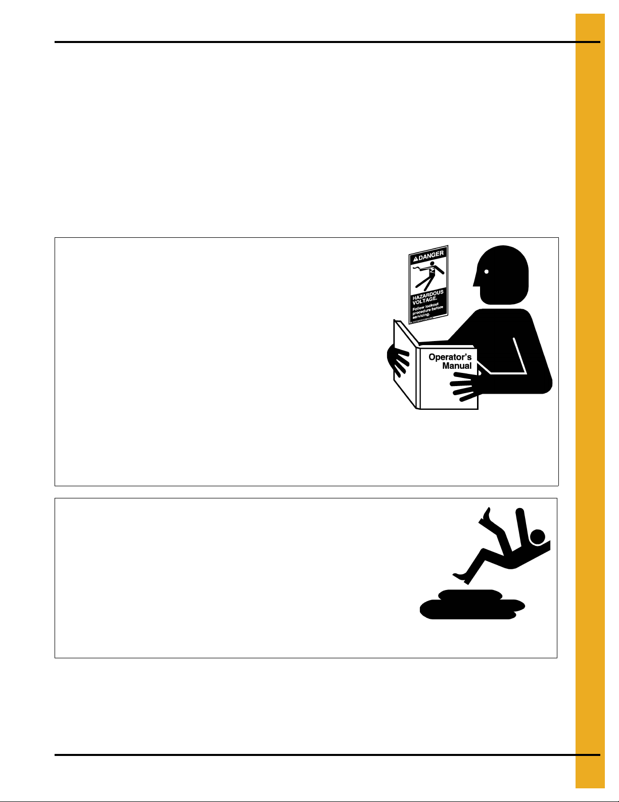
Follow Safety Instructions
Carefully read all safety messages in this manual and
safety signs on your machine. Keep signs in good
condition. Replace missing or damaged safety signs. Be
sure new equipment components and repair parts include
the current safety signs. Replacement safety signs are
available from the manufacturer.
Learn how to operate the machine and how to use controls
properly. Do not let anyone operate without instruction.
Keep your machinery in proper working condition.
Unauthorized modifications to the machine may impair
the function and/or safety and affect machine life.
If you do not understand any part of this manual or need
assistance, contact your dealer.
Read and Understand Manual
Practice Safe Maintenance
Understand service procedures before doing work. Keep area
clean and dry.
Never lubricate, service, or adjust machine while it is in operation.
Keep hands, feet, and clothing away from rotating parts.
Keep all parts in good condition and properly installed. Fix
damage immediately . Replace worn or broken p arts. Remove any
built-up grease, oil, and debris.
Maintain Equipment
and Work Area
Safety Instructions
Our foremost concern is your safety and the safety of others associated with this equipment. We want to
keep you as a customer. This manual is to help you understand safe operating procedures and some
problems that may be encountered by the operator and other personnel.
As owner and/or operator, it is your responsibility to know what requirements, hazards, and precautions
exist, and to inform all personnel associated with the equipment or in the area. Safety precautions may be
required from the personnel. Avoid any alterations to the equipment. Such alterations may produce a very
dangerous situation where SERIOUS INJURY or DEATH may occur.
This equipment shall be installed in accordance with the current installation codes and applicable
regulations, which should be carefully followed in all cases. Authorities having jurisdiction should be
consulted before installations are made.
PNEG-1092 30° Bin Roof Construction 7
Page 8
1. Safety
Prepare for Emergencies
Be prepared if fire starts.
Keep a first aid kit and fire extinguisher handy.
Keep emergency numbers for doctors, ambulance service,
hospital, and fire department near your telephone.
Keep Emergency Equipment
Quickly Accessible
Wear Protective Clothing
Wear close-fitting clothing and safety equipment appropriate
to the job.
Remove all jewelry.
Tie long hair up and back.
Wear safety glasses at all times to protect eyes from debris.
Wear gloves to protect your hands from sharp edges on plastic
or steel parts.
Wear steel-toed boots to help protect your feet from falling
debris. Tuck in any loose or dangling shoestrings.
A respirator may be needed to prevent breathing potentially
toxic fumes and dust.
Wear a hard hat to help protect your head.
Wear appropriate fall protection equipment when working at
elevations greater than six feet (6').
Eye Protection
Gloves
Steel-Toed Boots
Respirator
Hard Hat
Fall Protection
8 PNEG-1092 30° Bin Roof Construction
Page 9

1. Safety
Safety Sign-Off Sheet
As a requirement of O.S.H.A., it is necessary for the employer to train the employee in the safe operating
and safety procedures for this auger. This sign-off sheet is provided for your convenience and personal
record keeping. All unqualified persons are to stay out of the work area at all times. It is strongly
recommended that another qualified person who knows the shut down procedure be in the area in the
event of an emergency.
Date Employee Name Supervisor Name
PNEG-1092 30° Bin Roof Construction 9
Page 10

1. Safety
Proper Storage of Grain Bin/Silo Materials Prior to Construction
Wet storage stain (rust) will develop when closely packed bundles of galvanized material, such as sidewall
and roof sheets, have moisture present. Inspect roof and sidewall bundles on arrival for any moisture. If
moisture is present, it must not be allowed to remain between the she ets. Separate the sheets or panels
immediately and wipe them down. Spray with a light oil or diesel fuel.
If possible, sidewall bundles, roof sheets and other closely packed galvanized materials should be stored
in a dry, climate controlled building. If outdoor storage is unavoidable, the materials should be stored so
that they are raised above the ground and vegetation. Any stacking an d spacing mat erials sho uld not be
corrosive or wet. Be sure to protect materials from the weather, but permit air movement around the
bundles if possible.
Storing roof bundles and sidewall sheets at a slight incline can also help minimize the presence of
moisture. Storing the bundles with the center of the dome up (like an arch) is one option for minimizing
moisture during storage. Sidewall bundles can also be stored on edge but must be secured so that they
do not fall over and cause injury.
If “white rust” or “wet storage stain” occurs, contact the manufacturer immediately about ways to minimize
the adverse effect upon the galvanized coating.
10 PNEG-1092 30° Bin Roof Construction
Page 11
2. Decals
The manufacturer does not warrant any roof damage caused by excessive vacuum or internal
pressure from fans or other air moving systems. Adequate ventilation and/or “makeup air” devices
should be provided for all powered air handling systems. The manufacturer does n ot recommend
the use of downward flow systems (suction). Severe roof damage can result fro m any blockage of
air passages. Running fans during high humidity/cold weather conditions can cause air exhaust
or intake ports to freeze.
CAUTION!
Excessive vacuum (or pressure) may
damage roof. Use positive aeration
system. Make sure all roof vents are
open and unobstructed. Start roof
fans when supply fans are started.
Do not operate when conditions exist
that may cause roof vent icing.
DC-969
PNEG-1092 30° Bin Roof Construction 11
Page 12
2. Decals
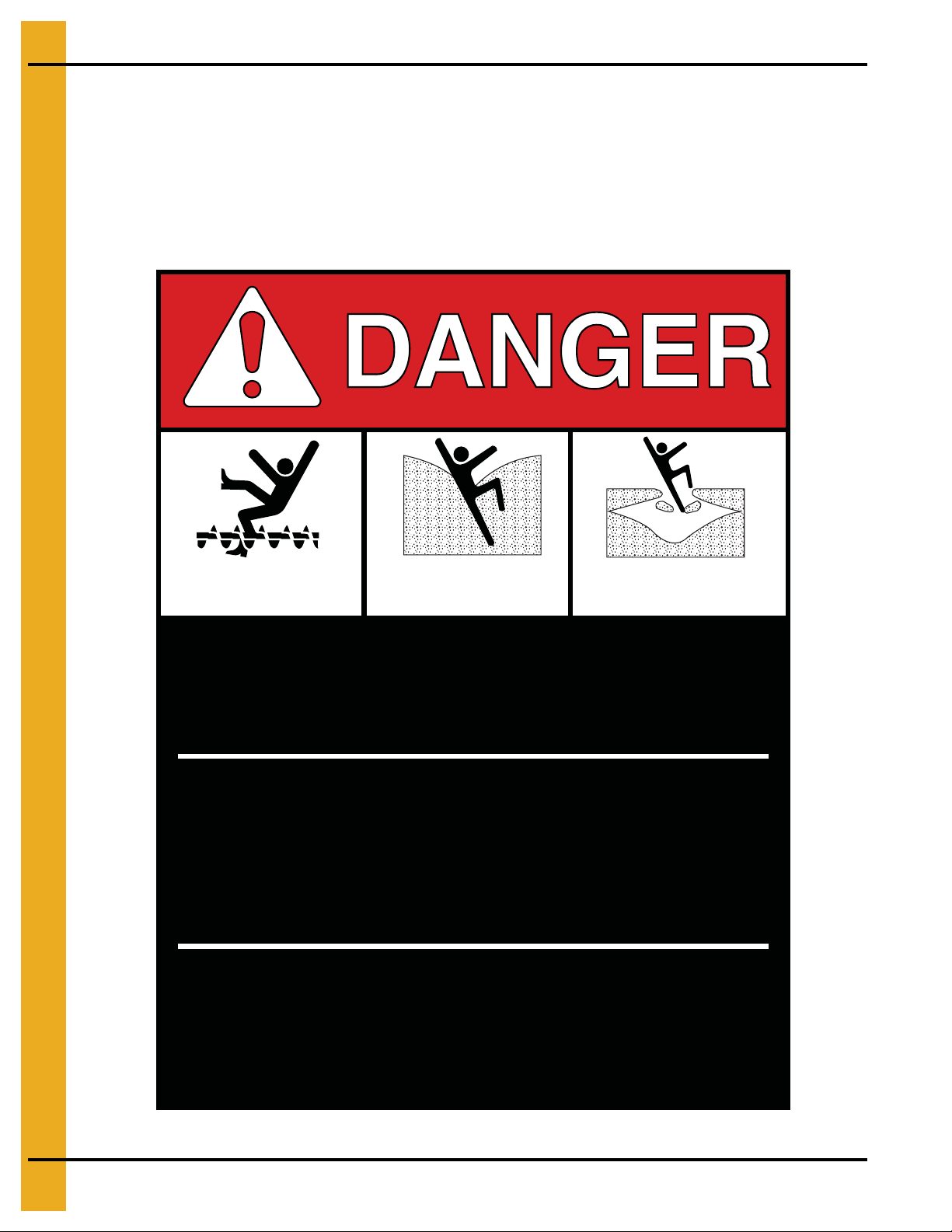
Rotating flighting will
kill or dismember.
Flowing material will
trap and suffocate.
Crusted material will
collapse and suffocate.
Keep clear of all augers.
DO NOT ENTER this bin!
Failure to heed these
warnings will result in
serious injury or death.
If you must enter the bin:
1. Shut off and lock out all power.
2. Use a safety harness and safety line.
3. Station another person outside the bin.
4. Avoid the center of the bin.
5. Wear proper breathing equipment or respirator.
DC-GBC-1A
ATTENTION: The decal shown below should be present on the outside of the door cover of the 2 ring,
24" porthole door cover and roof manway cover. If a decal has been damaged or is missing in any of these
locations, contact the manufacturer for a free replacement decal.
GSI Decals
1004 E. Illinois St.
Assumption, IL. 62510
Phone: 1-217-226-4421
12 PNEG-1092 30° Bin Roof Construction
Page 13
2. Decals
ATTENTION: The decal shown below should be present on the outside of the door cover of the 2 ring,
24" porthole door cover and roof manway cover. If a decal has been damaged or is missing in any of these
locations, contact the manufacturer for a free replacement decal.
GSI Decals
1004 E. Illinois St.
Assumption, IL. 62510
Phone: 1-217-226-4421
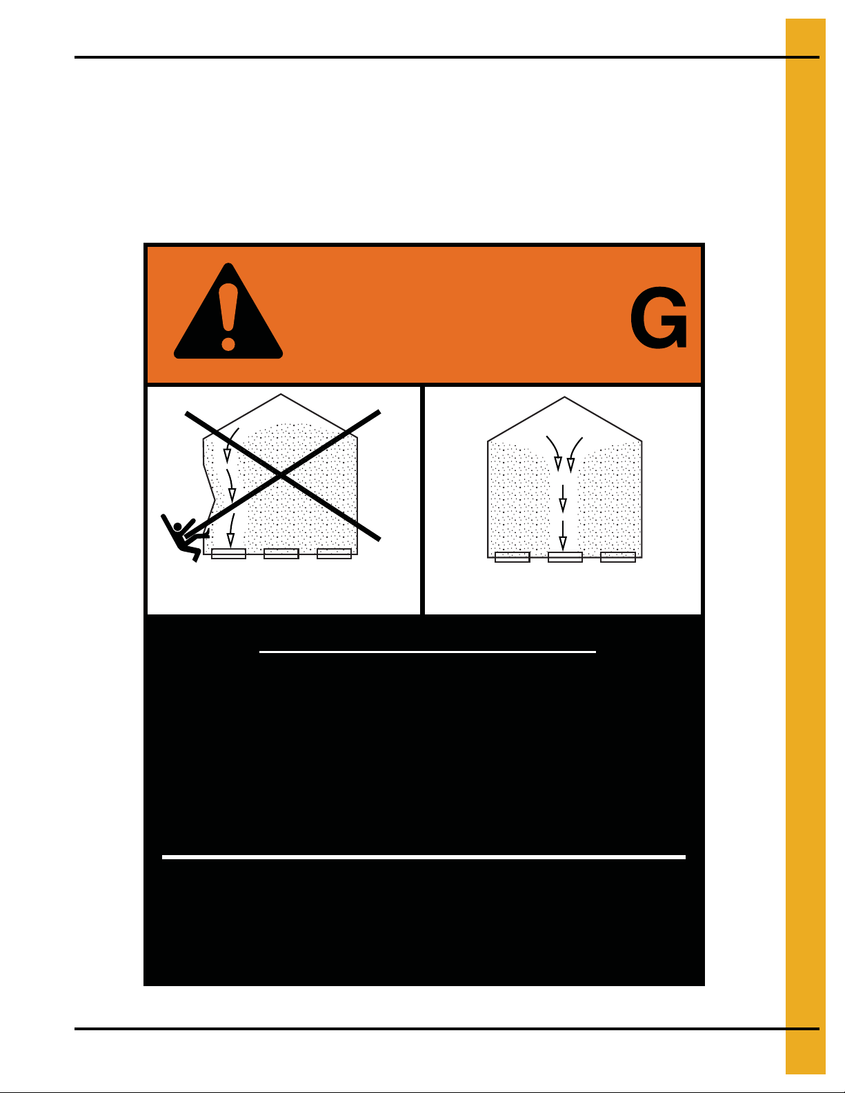
WARNIN
DON’T
DO
UNLOADING INSTRUCTIONS:
1. Use CENTER FLOOR OUTLET ONLY until NO grain
remains above this outlet.
2. Side floor outlets to be used ONLY when above
condition is satisfied.
3. Lock all side floor outlets to avoid accidental
premature use.
4. See manufacturers instructions for proper use of
factory supplied sidedraw (wall) discharge systems.
Failure to heed these warnings
could result in serious injury, death,
structural damage or collapse of tank.
DC-GBC-2A
PNEG-1092 30° Bin Roof Construction 13
Page 14
2. Decals
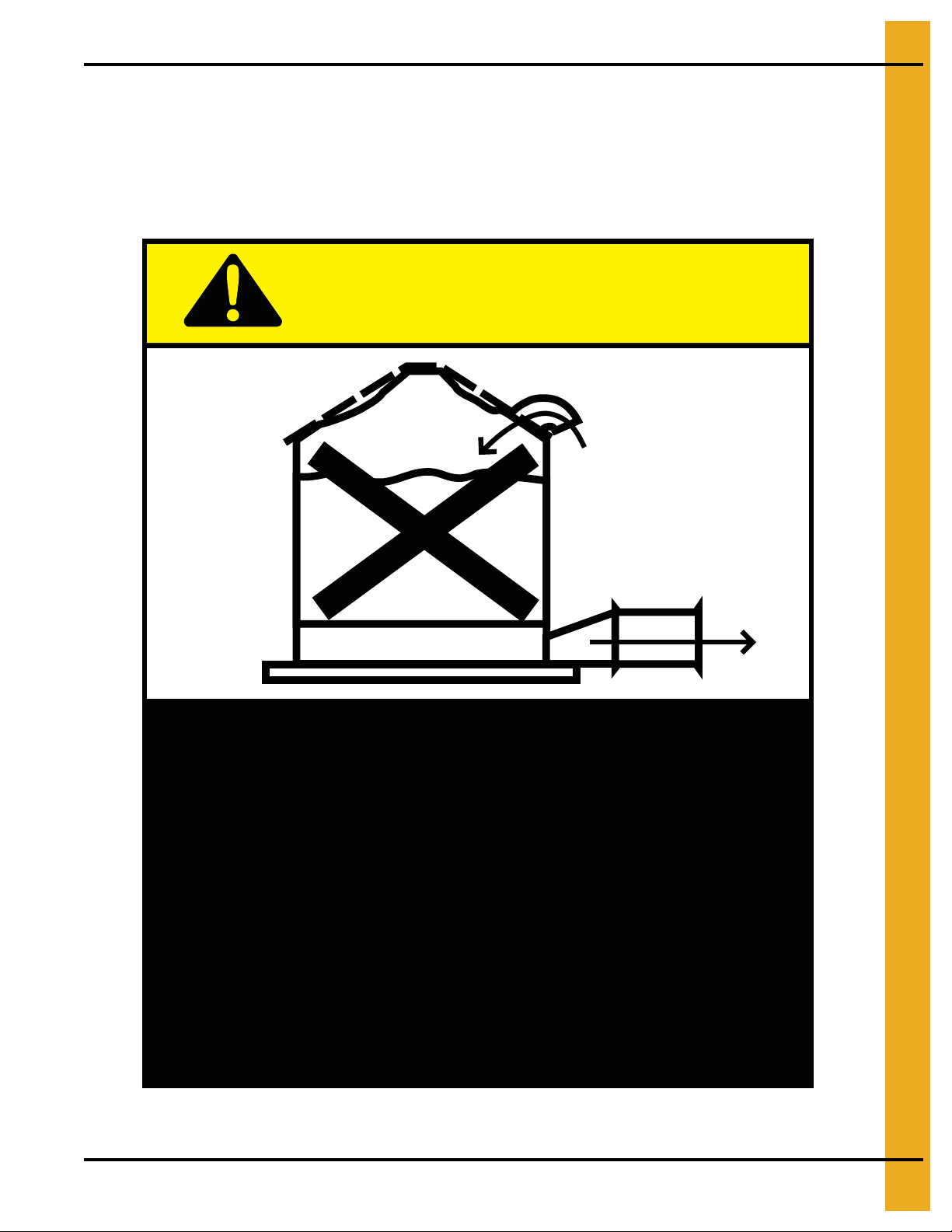
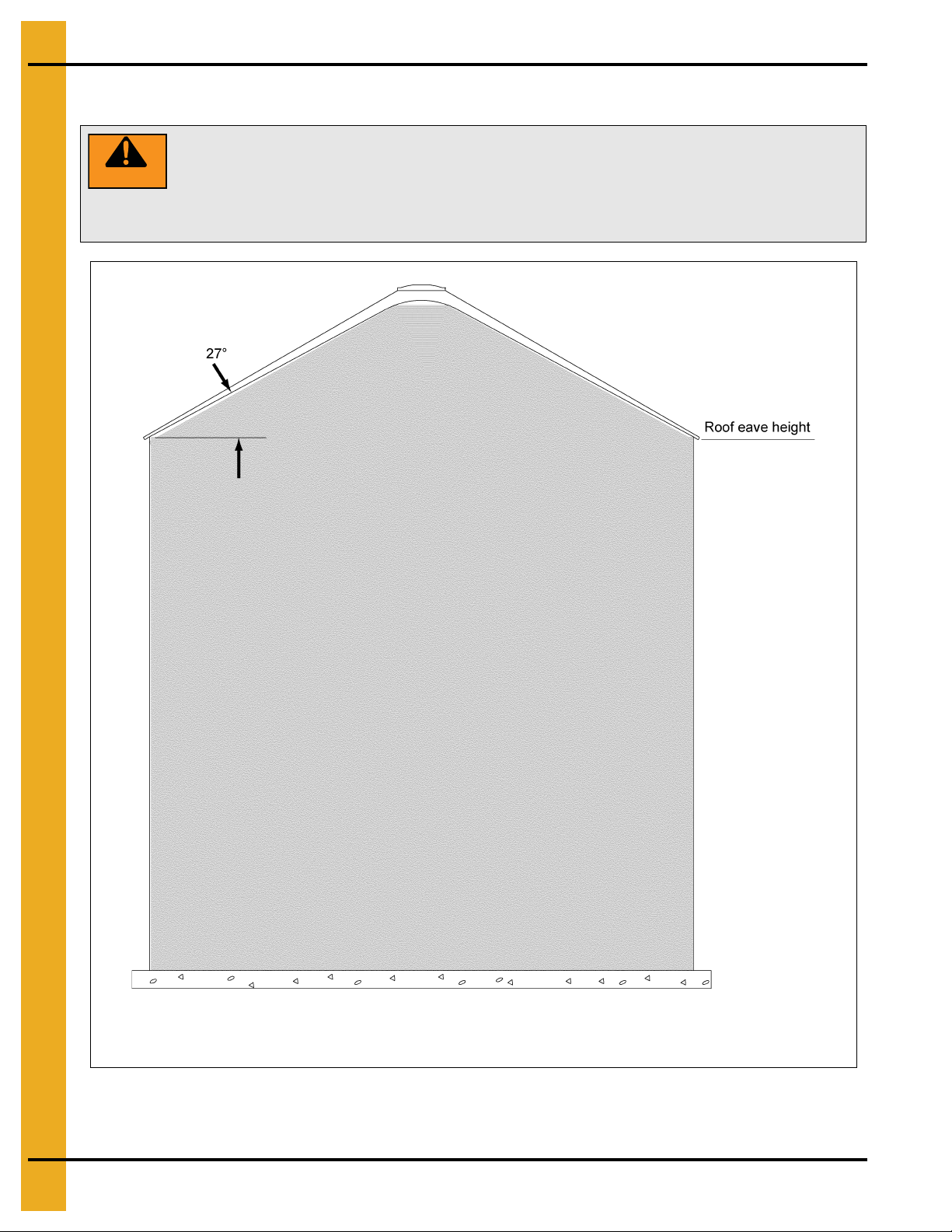
WARNING
DO NOT OVERFILL BIN. Stored grain, although heaped in the center, should
be no higher than the roof eaves at the outer edge. (See Figure 2A.) Filling the bin
above this point creates excessive internal pressure and may cause swelling and
eventual roof failure. The overfilling of a bin may also cause the blockage of roof
vents and eaves, which will lead to a build-up of air pressure causing roof damage.
(Based on grain with an angle of repose of 27°.)
Overfill Warning
Figure 2A Maximum Bin Capacity
14 PNEG-1092 30° Bin Roof Construction
Page 15
2. Decals
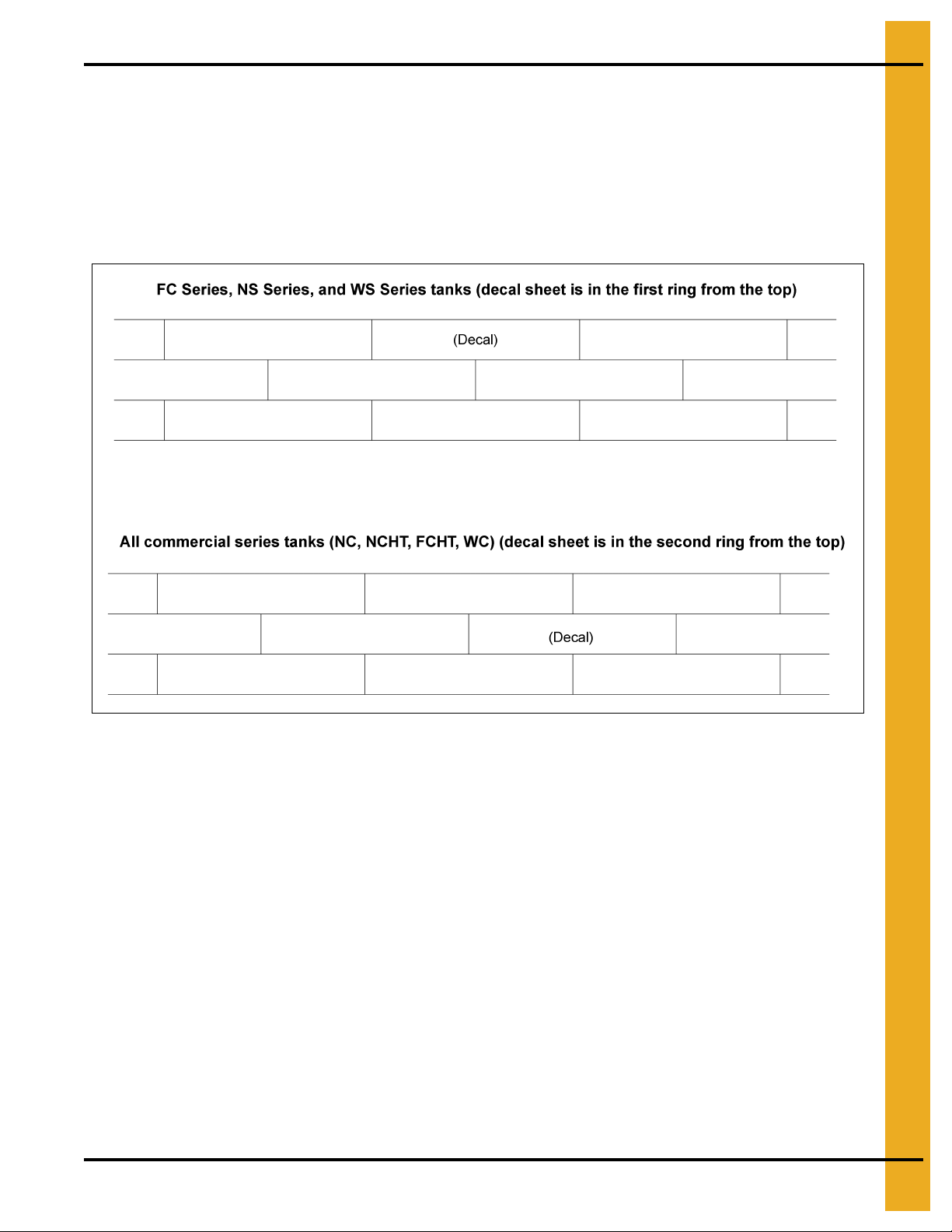
Proper Decal Sheet Placement
Prior to beginning roof construction, it is necessary to build at least 1 ring of the bin.
Refer to the Bin/Silo construction manual you received with the bin. This manual will be packaged in the
sidewall hardware box.
Note for several of the lines (WS, FC and NS), the sidewall sheet has a “top” and “bottom”. It is imp ortant
to refer to these details.
Figure 2B
PNEG-1092 30° Bin Roof Construction 15
Page 16
3. Bolt and Nut Usage
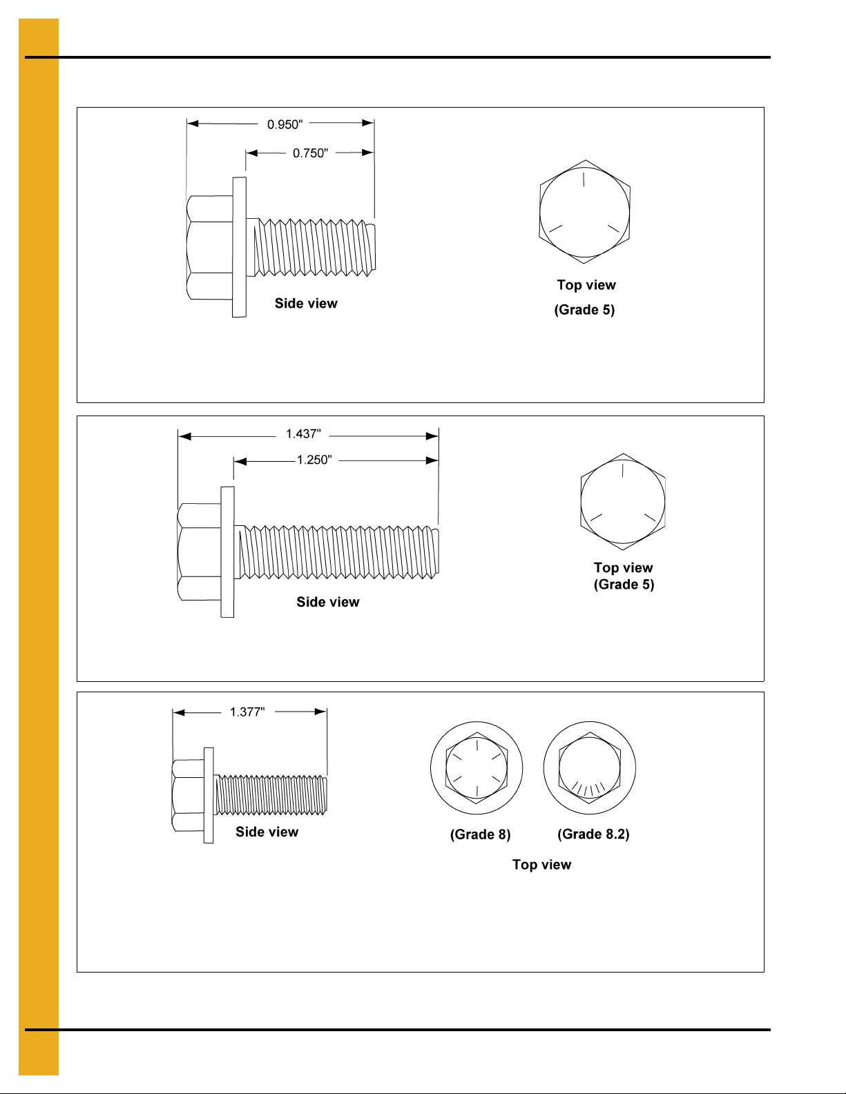
This bolt is used in attaching roof panels to the top sidewall sheet and attaching roof panels and flashing to the
center collar.
S
-
2
7
5
This bolt is primarily used to connect roof panels together where they overlap.
S
-
2
7
7
0.375" x 1.000" Hex flanged head without a plastic sealing washer. This bolt is used on the roof rafter splices for
commercial roof systems.
S
-
7
9
2
7
Bolt Usage
16 PNEG-1092 30° Bin Roof Construction
Page 17
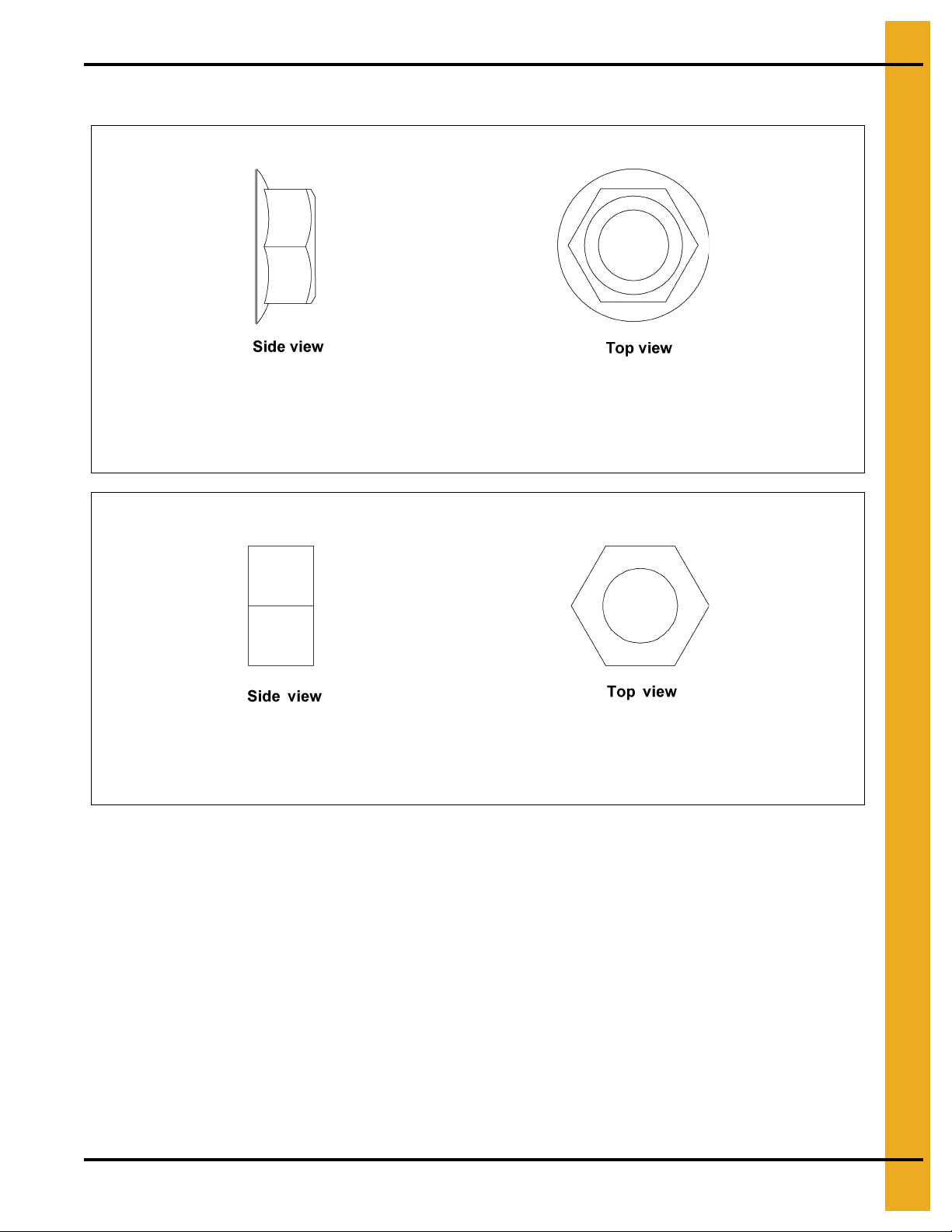
Nut Usage
This nut is used in attaching roof panels to the roof channels and to the sidewall sheets, as well as attaching roof panels
and flashing to the center collar.
S
-
3
6
11
0.3125 Serrated flange nut
This nut is primarily used in sidewall sheet connections.
0.3125 Hex nut
S
-
3
9
6
3. Bolt and Nut Usage
PNEG-1092 30° Bin Roof Construction 17
Page 18
4. Instructions
Stirring devices may create additional loads on grain bin sidewalls, roofs and
floors. If high-moisture grain is loaded too deep and too fast, unstiffened bin
walls can become overloaded. Observe the following installation and operation
procedures if the bin is to be equipped with the stirring device.
WARNING
Instructions for Stirring Devices
Bins are offered in more than one structural series for specific uses. To maintain the warranty, the
appropriate “series” grain bin must be used. Consult the sales catalog or contact the Engineering
Department for current recommendations. Note that the use of any stirring device with three (3) or more
vertical screws may require a heavier than “standard” series bin. Any re-circulating device or system
should be used in the “re-circulating” series bins. NOTE: For GSI bins larger than 33' diameter an
alternate method of mounting is to attach suspension chain to intermediate center collar.
1. Read owner’s manual for the stirring device and follow all instructions se t fort h by th e manufa cture r.
IMPORTANT: Install the switch for the stirring device near the roof manway opening so that the
unit can be observed while stirring.
2. Make sure there are no obstructions, such as protruding ladders.
3. After loading approximately 3' of grain, run the unit one complete revolution to determine if it is
working properly.
4. If the unit is functioning properly, operate the stirring device continuously while filling and drying to
avoid compacted grain around the vertical screws.
5. If it becomes necessary to stop a stirring device using laterally moving screws, try to stop it with the
vertical screws nearest to the center of the bin, away from the sidewall. Should a device stop or stall
for any reason and remain inoperable for any length of time, the auger carriage should be supported
to the grain surface before restarting. The vertical auger should be turned by hand, with a pipe
wrench, before power is applied.
6. For best results, fill the bin to one-half of the final intended depth. Dry grain to 16% and continue
filling. Use filling rates specified by stirring device manufacturer. If necessary to fill to the top wit hout
stopping, reduce the filling rate and drying air temperature so that th e stirrin g rate ca n keep up with
the drying rate.
7. Do not overfill bin. Filling should be stopped at bottom of top ring or 30" below the track.
8. The preceding steps are only general instructions which apply to the majority of stirring devices.
Since there are different manufacturers of these devices, it is importan t to read the operator’s manual
thoroughly for specific instructions applicable to the machine.
18 PNEG-1092 30° Bin Roof Construction
Page 19
4. Instructions
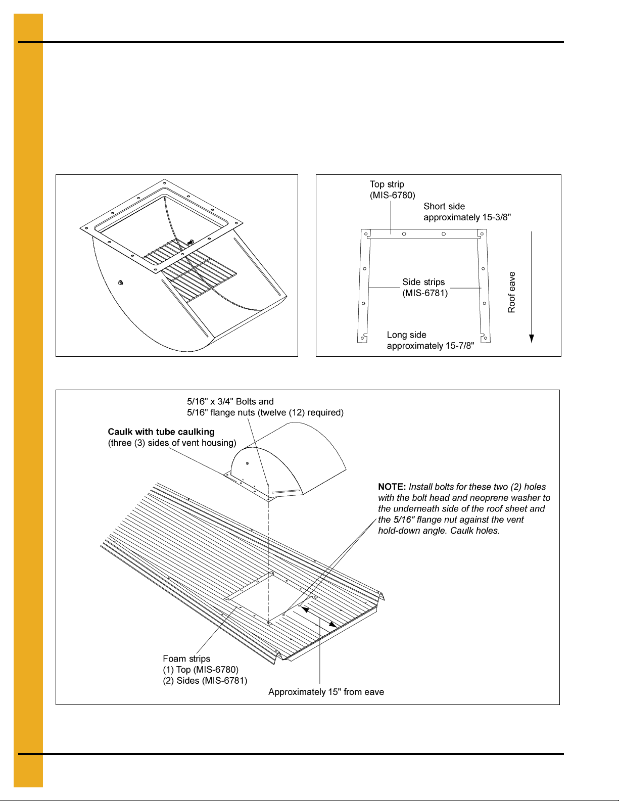
Auto-Vent Assembly and Installation Instructions
The following instructions are for assembling and installing the Auto-Vent. First, check the packing list to
ensure all components have been shipped. The unit is easiest assembled in the upside down position
as shown in the instructions.
Assembly
1. Take all parts out of the shipping box and check if all parts are present.
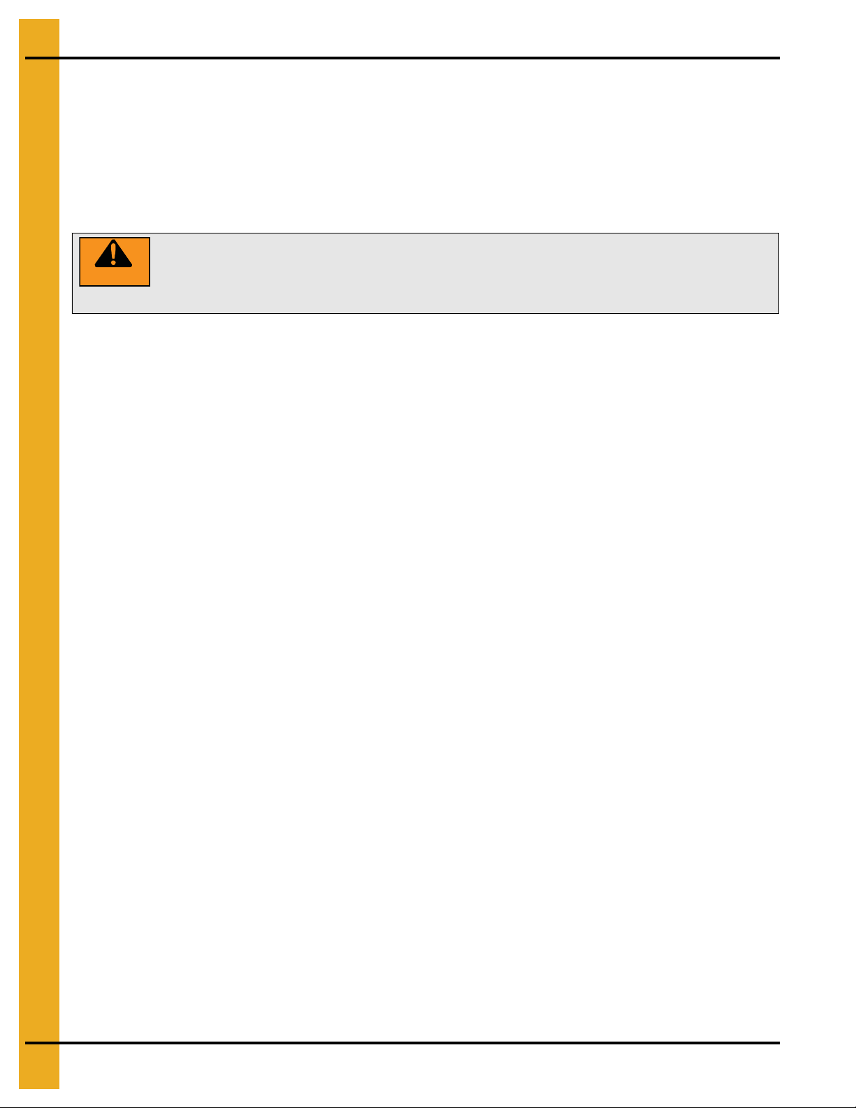
2. Turn one roof vent housing (MIS-6778) upside down. (See Figure 4A.)
3. Insert 5/16" x 1-1/4" bin bolt with neoprene washer through hole in the side of roof vent. Place
jamb nut onto the bolt and tighten. (See Figure 4A.)
4. Slide flap assembly (MIS-6777) on to bolt. The bolt should slide through hole in the flap assembly
bracket. Install with curvature cupped upward and the brackets in the position as shown in
5. Insert 5/16" x 1-1/4" bin bolt with neoprene washer through the other side of the roof vent, through
jamb nut and other flap assembly bracket. Tighten nut against vent housing side.
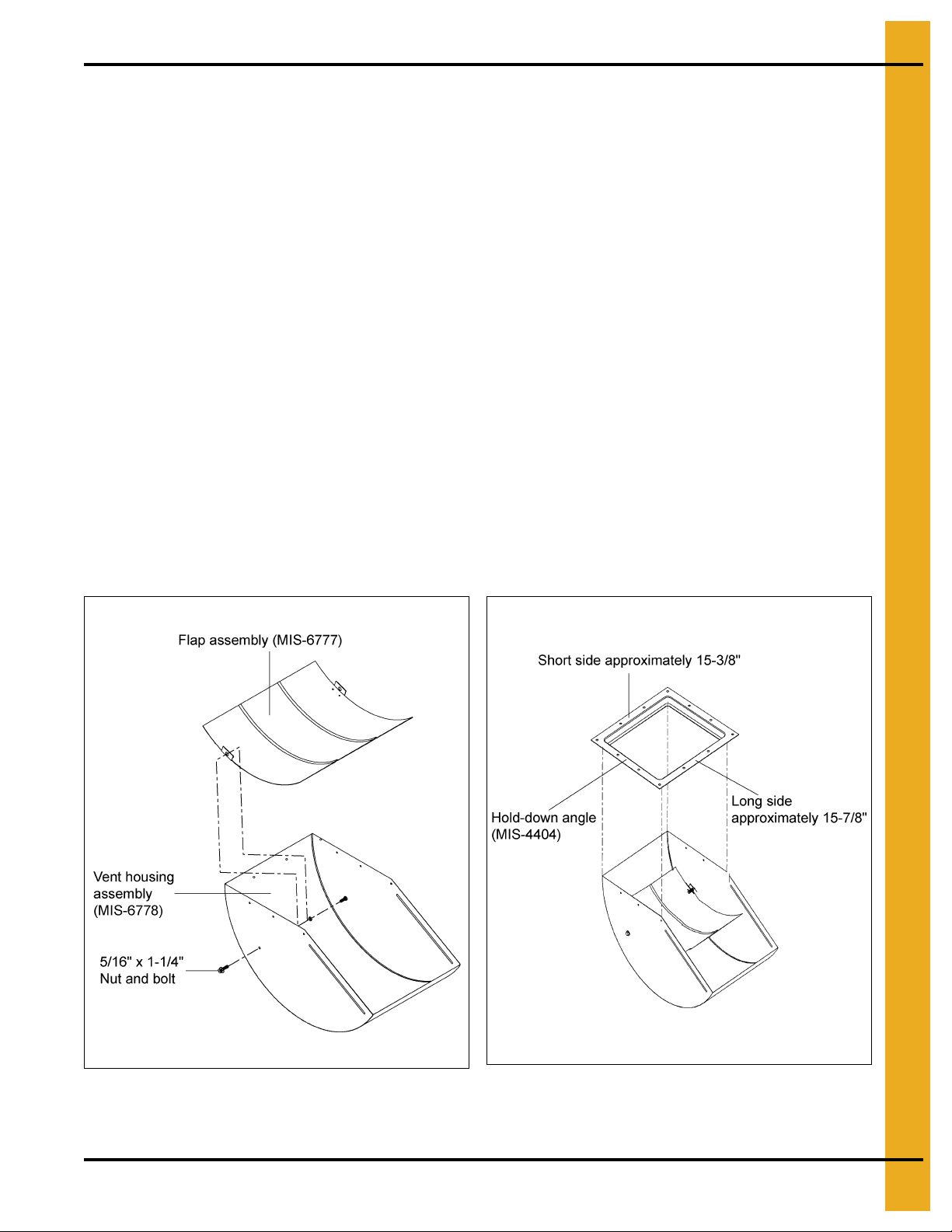
6. Apply a bead of tube caulking around three (3) housing sides of the roof vent where it meets the
hold-down angle.
Figure 4A
.
7. Place hold-down angle (MIS-4404) on the assembled roof vent. The wide end o f the hold-down angle
must face vent discharge. Once aligned, screw nine (9) #10 self-drilling (S-280) screws through the
roof housing and into the hold-down angle. (See Figure 4B.)
Figure 4A
PNEG-1092 30° Bin Roof Construction 19
Figure 4B
Page 20
4. Instructions
Installation
8. If the roof sheet does not have a pre-punched hole for t he roof vent, a hole must be cut. The cut hole
should match the roof vent. The hole’s inside edge should be approximately 15" from the eave.
(See Figure 4E.)
9. Place the three (3) foam strips on roof sheet, as shown in Figure 4D. Position roof vent over foam
strips and bolt down using 5/16" x 3/4" bin bolts and nuts. NOTE: See Figure 4E below for lower
two (2) bolts of vent.
Figure 4C
Figure 4D
Figure 4E
20 PNEG-1092 30° Bin Roof Construction
Page 21
4. Instructions
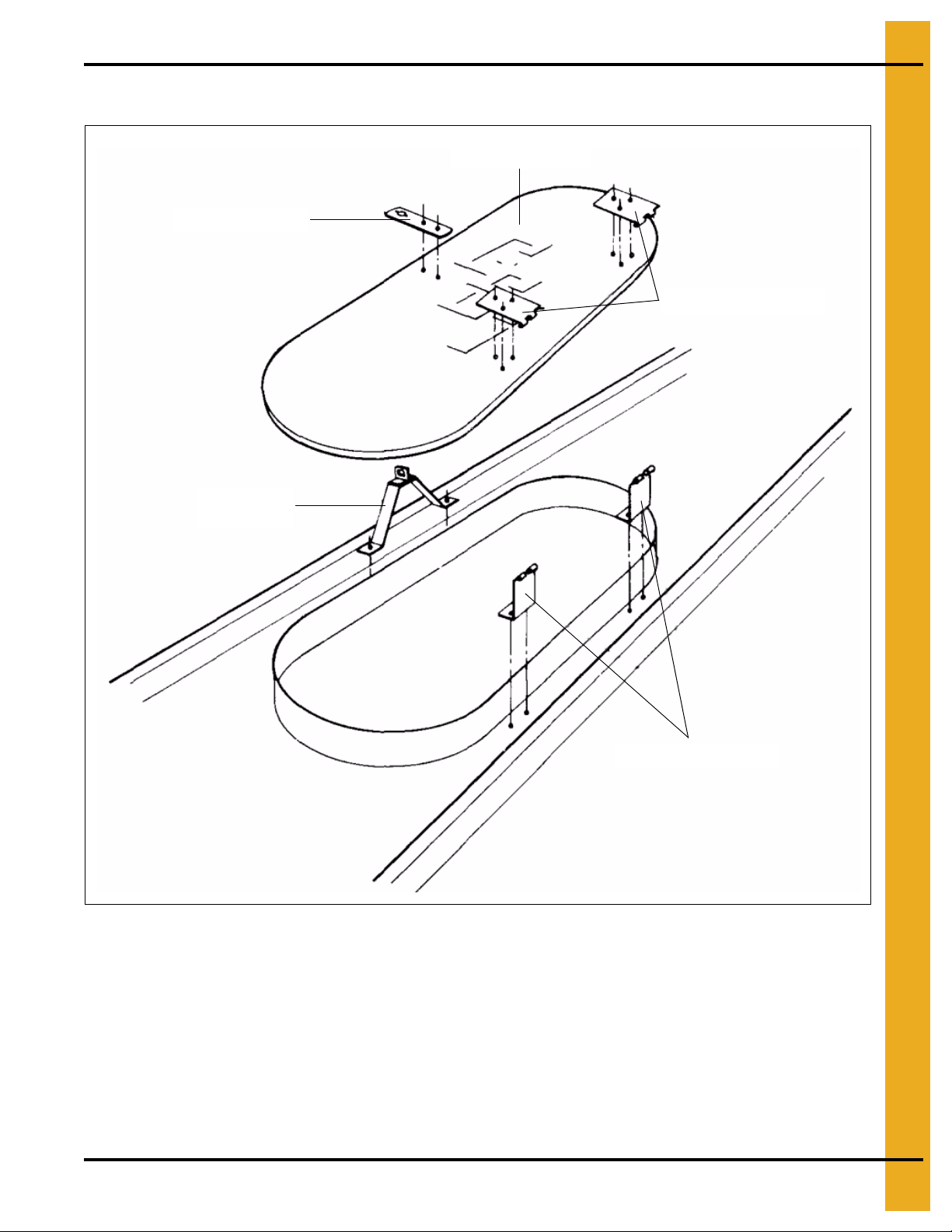
Wire Grill Guard Roof Vent Assembly and Installation Instructions
The following instructions are for assembling and installing the wire grill guard roof vent. Before beginning
assembly, check the packing list to ensure all components have been received. The unit is easiest
assembled in the upside down position as shown in Figure 4F. Locate the roof vent as shown in
Figure 4J on Page 22.
Assembly
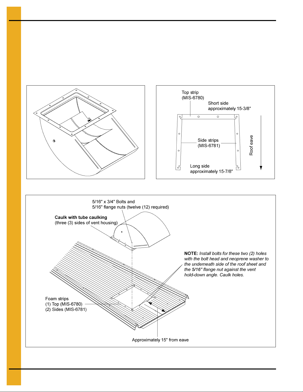
1. Turn one roof vent housing (MIS-6778) upside down. (See Figure 4F.)
2. Insert 5/16" x 1-1/4" bin bolt with neoprene washer through the hole in the side of the roof vent. Place
jamb nut onto the bolt and tighten. (See Figure 4F.)
3. Slide one eyelet of grill guard onto the 5/16" bin bolt.
4. Insert 5/16" x 1-1/4" bin bolt with neoprene washer through the other side of the roof vent, through
jamb nut and other eyelet of grill guard. Tighten nut against vent housing side.
5. Apply a bead of tube caulking around the three (3) housing sides of the roof vent where it meets the
hold-down angle.
6. Place hold-down angle (MIS-4404) on the assembled roof vent. The wide end o f the hold-down angle
must face the vent discharge. Once aligned, screw nine (9) #10 self-drilling (S-280) screws through
the roof housing and into the hold-down angle. (See Figure 4G.)
Figure 4F Figure 4G
PNEG-1092 30° Bin Roof Construction 21
Page 22
4. Instructions
Installation
7. If the roof sheet does not have a pre-punched hole for the roof vent, a hole must be cut. Cut the hole
to match the roof vent. The inside edge of the hole should be approximately 15" from the eave.
(See Figure 4J.)
8. Place the three (3) foam strips on roof sheet, as shown in Figure 4I. Position roof vent over foam
strips and bolt down using 5/16" x 3/4" bin bolts and nuts. NOTE: See Figure 4J for lower two (2)
bolts of vent.
Figure 4H Figure 4I
Figure 4J
22 PNEG-1092 30° Bin Roof Construction
Page 23
72'-135' Obround Manway Cover
Lower hinges (MW-291)
Hinge plates (MW-272)
Manway cover with
decals (MW-008D)
Latch bar (MW-271)
Latch bracket
(MW-1439)
5. Manway Cover Assembly
Bolt hinge plates and latch bar to manway first. Then bolt lower hinges and latch bracket to roof panel.
Place center cover over port and insert pivot bolts into hinges. (See Figure 5A.)
PNEG-1092 30° Bin Roof Construction 23
Figure 5A Manway Cover Assembly
Page 24
5. Manway Cover Assembly
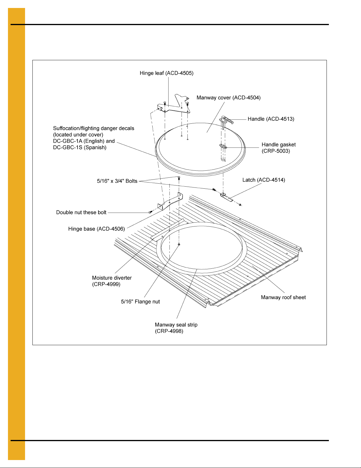
Round Manway Cover
Round manway cover detail for bins 60' and smaller.
Figure 5B
Apply caulking to underneath side of moisture diverter to seal between the corrugated roof sheet and
diverter. Attach the moisture diverter and hinge base to manway roof sheet with 5/16" x 3/4" bolts and nuts.
Place hinge leaf on manway cover and bolt both hinge parts together with 3/8" x 1" bolts and lock nuts.
Attach the handle with two (2) #10-24 x 5/8" long bolts and #10-24 lock nuts. Slip a 5/16" nut in the latch
bar, thread on the shaft of handle and adjust latch bar so it will catch the bottom side of the manway sheet.
Snap the manway seal strip to the manway seal. (See Figure 5B.)
24 PNEG-1092 30° Bin Roof Construction
Page 25
6. Center Collar Details
The standard roof with a dome cap lid will have a center collar assembled from three (3) pieces. The
dome cap will mount onto it as well as the flashing. The dome cap is standard on all 12'-48' bins and
54'-60' FCDL, WSL and NSL series bins. A flat top is standard on all 39'-60' NCL and WCL commercial
series bins.
For the 33'-48' dome cap bins, this will be the upper or “top” center collar. The lower or “Z” center collar
details are given on the later pages.
54'-60' dome cap bins and 33' and larger flattop bins do not have the top center collar.
Figure 6A
PNEG-1092 30° Bin Roof Construction 25
Page 26
7. Farm Roof Assembly
Farm Roof Assembly
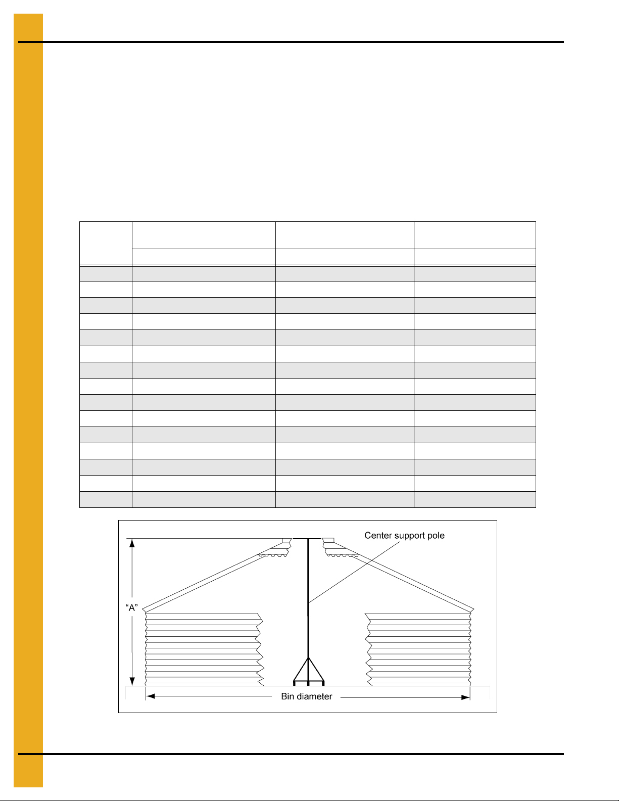
After completing the first sidewall ring, you are ready to begin construction. Begin with the center collar
sections. For convenience in opening and closing the center cover, the roof ladder and manhole sheet
should be placed directly opposite the two (2) slide rod holes in the center collar. Next build a roof center
support to hold the peak in place at the proper height. A simple structure composed of a sturdy cross
arm attached to a pole and supported by a platform or scaffolding will do. Stand the center support directly
in the center of the bin. The following dimensions are approximate distances used in bin roof construction.
Adjusting the center support height will ease roof erection. Place eave clips inside the bin wall to maintain
an opening around the top of the sidewall. This allows condensation, which normally collects on the
underneath side of the roof panels, to flow freely to the outside of the bin, thus avoiding possible
grain spoilage.
Bin
Diameter
12' 6'-9" 5'-9'' 8'-5"
15' 7'-7'' 6'-7'' 9'-3"
18' 8'-5'' 7'-5'' 10'-1"
21' 9'-4'' 8'-4'' 11'-0"
24' 10'-2'' 9'-2'' 11'-10"
27' 11'-0'' 10'-0" 12'-8"
30' 11'-11'' 10'-11" 13'-7"
33' 12'-2" 11'-2'' 13'-10"
36' 13'-1'' 12'-1" 14'-9''
39' 14'-4" 13'-4" 16'-0''
42' 14'-10'' 13'-10" 16'-6''
45' 15'-6" 14'-6" 17'-2''
48' 16'-4" 15'-4" 18'-0"
54' 16'-9" 15'-9" 18'-5"
60' 18'-6" 17'-6" 20'-2"
Use with 1 Ring of
4.00'' Corrugated Sidewall
“A” “A” “A”
Use with 1 Ring of
2.66'' Corrugated Sidewall
Use with 2 Ring of
2.66'' Corrugated Sidewall
Figure 7A
26 PNEG-1092 30° Bin Roof Construction
Page 27
7. Farm Roof Assembly
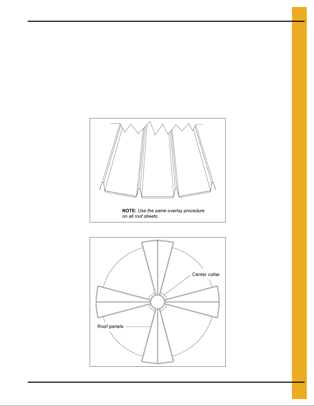
For best results in erecting the roof, install two (2) roof panels in four (4) places as shown in Figure 7C.
When these eight (8) panels are in place, the peak assembly should be centered. Next add two (2) or
three (3) panels at a time to each section making certain to la p them the same way, until all panels are in
place. Be sure the panels are bolted loosely. DO NOT TIGHTEN BOLTS UNTIL THE ROOF IS
COMPLETELY ASSEMBLED. When installing the roof panels, take into consideration placing the
manway for ease of access to and from the sidewall and roof ladders. On Stiffened tanks, particularly
on NCHT and FCHT series hopper tanks, location of the manway panel and roof ladder in relation
to the stiffeners is crucial for proper installation of the ladder system. Refer to PNEG-1451
for detailed instructions on NCHT and FCHT manuals and PNEG-1420 for flat bottomed
stiffened tanks (FCDL, NCL, WCL Series). These manuals are packaged with the ladder and
safety cage packages.
Fasten roof sheets to eave clips and sidewall sheets as you assemble.
Figure 7B Roof Overlay
Figure 7C
PNEG-1092 30° Bin Roof Construction 27
Page 28

7. Farm Roof Assembly
Roof Assembly for 12' through 24' Bins
NOTE: Be sure to install ladder rungs and safety steps as you assemble roof panels. When assembling
such pieces as roof ladder rungs, use 5/16" x 1-1/4" bolts with a flat washer on top of the slot and
extra neoprene washer between the roof and the piece being added. This will ensure a more
protective seal against moisture.
Figure 7D
28 PNEG-1092 30° Bin Roof Construction
Page 29

7. Farm Roof Assembly
Roof Assembly for 12' through 24' Bins (Continued)
To assemble slide rods and cover, insert straight end of slide rod through th e center collar and thread one
5/16" nut all the way down on the rod. Then place rod through the cover and put a washe r and nut on the
outside. DO NOT TIGHTEN. Insert rod through the cover, then place washer and nut on the outside.
TIGHTEN. Adjust and tighten nuts on straight end of rod. After tightening, it may be necessary to spread
the rods slightly to make them parallel. Maintain 10" between rods.
Figure 7E Section through Center Collar
Figure 7F Top View
PNEG-1092 30° Bin Roof Construction 29
Page 30

7. Farm Roof Assembly
NOTE: Refer seal clip details on Page 31.
Flashing (See Figure 7I on Page 31.)
Roof Assembly for 27' through 30' Bins
NOTE: Be sure to install ladder rungs and safety steps as you assemble roof panels. When assembling
such pieces as roof ladder rungs, use 5/16" x 1-1/4" bolts with a flat washer on top of the slot and
extra neoprene washer between the roof and the piece being added. This will ensure a more
protective seal against moisture.
Figure 7G
30 PNEG-1092 30° Bin Roof Construction
Page 31

7. Farm Roof Assembly
Roof Assembly for 27' through 30' Bins (Continued)
NOTE: Reference seal clip details on Page 32.
NOTE: See Pages 29 and 30 for assembling the peak cap and slide rods.
Prior to assembly of roof and center collar, you will need to position the flashing so the ca p hold-do wn
is in line with roof ladder. Two (2) holes per flashing section are provided for the hold-down bracket.
Pre-assemble center collar and flashing pieces together before attaching roof panels to flashing.
ALL BOLTS, EXCEPT FOR THE TWO (2) LOWER FLASHING SEAM BOLTS.
TIGHTEN
Figure 7H Cross Section View
Figure 7I Flashing Detail
PNEG-1092 30° Bin Roof Construction 31
Page 32

7. Farm Roof Assembly
Roof Assembly for 27' through 30' Bins (Continued)
After all roof panels have been attached to the roof flashing, slip the roof panel seal clip between the
bottom of the flashing and the top of the roof ribs. Be sure to push the clip in as far as possible for the best
seal. Tighten all bolts and nuts after clips are pushed in.
Figure 7J Cross Section
Figure 7K Isometric View
32 PNEG-1092 30° Bin Roof Construction
Page 33

7. Farm Roof Assembly
Roof Assembly for 33' through 48' Roofs with Standard Peak Cap
NOTE: Additional instructions are given on the following pages for 42' diameter and larger farm bin and
commercial bin roofs. For 36' diameter hopper tanks (NCHT), refer to special instructions included
in the 36' NCHT manual.
After assembling the lower center collar “Z” ring, build a roof center support to hold it in place at the proper
height, as shown in Figure 7A and Chart on Page 26. A simple stru cture composed of a sturdy cross-arm
attached to a pole and supported by a platform or scaffolding in the center of the bin will be sufficient.
Place eave clips inside the bin wall to maintain an opening around the top of the sidewall. This allows
condensation, which normally collects on the underneath side of the roof panels, to flow freely to the
outside of the bin, thus avoiding possible grain spoilage.
Now you are ready to place the first group of roof sheets in place as shown in Figure 7C on Page 27. These
eight (8) panels will keep the peak assembly centered. Continue placing roof sheets (with a consistent lap
pattern) at intervals around the bin to distribute the weight evenly. DO NOT TIGHTEN BOLTS UNTIL THE
ROOF IS COMPLETELY ASSEMBLED. Once all roof sheets are in place and the bolts are tightened, the
center ring and flashing assembly may be placed on top of the panels. Place a flashing seam over a
“Z” collar seam to ensure correct alignment. Refer to Figure 7M on Page 34. The peak cap and slide rods
may then be put in place to finish the roof. On stiffened tanks, particularly on NCHT series hopper
tanks, location of the manway panel and roof ladder in relation to the stiffeners is crucial for proper
installation of the ladder systems. Refer to PNEG-1451 for detailed instructions on the NCHT series
and PNEG-1420 for flat bottomed stiffened tanks (FCDL, NCL and WCL series). These manuals are
included with the ladder and safety cage packages.
Figure 7L
PNEG-1092 30° Bin Roof Construction 33
Page 34

7. Farm Roof Assembly
Important
Roof Assembly for 33' through 48' Roofs with Standard
Peak Cap (Continued)
Figure 7M Center Collar Flashing Assembly
34 PNEG-1092 30° Bin Roof Construction
Page 35

7. Farm Roof Assembly
NOTE: See Page 34 for details on which center collar holes are used for flashing attachment.
Roof Assembly for 33' through 48' Roofs with Standard
Peak Cap (Continued)
NOTE: See Pages 33 and 34 for assembling the peak cap and slide rods.
Figure 7N
PNEG-1092 30° Bin Roof Construction 35
Page 36

8. Support Ring Instructions
WARNING
DO NOT OVERFILL BIN. Stored grain, although heaped in the center, should
be no higher than the roof eaves at the outer edge. Filling the bin above this
point creates excessive internal pressure and may cause swelling and eventual
failure of the roof.
Ring Instructions
Be sure to install ladder rungs and safety steps as you assemble roof panels. (See Figure 8A.) At this
point you will have completed assembly of the roof. Do not tighten bolts yet. Optional equipment and
accessories should now be installed.
NOTE: When assembling such pieces as roof ladder rungs, use 5/16" x 1-1/4" bolts with a flat washer on
top of the slot and extra neoprene washer between the roof and the piece being added. This will
ensure a more protective seal against moisture.
IMPORTANT: Maximum weight to be supported and/or suspended from the roof is to be 6000 pounds
for 12' through 48' (non-trussed) ONLY.
IMPORTANT: Maximum weight to be supported and/or suspended from the roof is 10000 lbs. for
commercial (trussed roof) 39'-60' flattop roof bins. Roof loads should be supported from
the flattop or at the second lower “Z” collar.
Figure 8A
36 PNEG-1092 30° Bin Roof Construction
Page 37

8. Support Ring Instructions
Roof Support Ring Instructions 30° Roof
Roof support rings are standard on all bins up to 48' diameter. A single support ring is standard for
15' diameter bins. Two (2) support rings are standard for 18'-48' diameter bins. All support rings will be
placed on the outside of the roof panels.
To determine the location of the support rings, start at the narrow or peak of the roof panel and count
each hole. Having counted down the required distance, as described in the Chart below, install the
appropriate brackets.
Expansion bolts should be fully contracted when assembling support rings. When you have completely
assembled both rings, (but prior to expanding the bolts) tighten all roof bolts including eave clip bolts.
Now extend expansion bolts by running the nut out on the threads. This procedure should be continued
evenly around the roof until the ring raises the roof to show a slight crown.
Support ring expansion bolts may become dislodged from the ring during high winds or when the inside
pressure of the bin is too great. If one expansion bolt is dislodged, the entire ring will become useless.
To prevent this, drill holes through the support ring and expansion bolt (after the rings have been installed
and expanded to the correct size) and insert a cotter pin or bolt through each hole.
NOTE:
Welding of the expansion n uts to the pipe and expansion bolts or staking the expansion bolt
threads to prevent the movement of the jamb nut may be done as an option to drilling and pinnin g.
Bin Diameter
Support Ring Location
15 (T)
18 (T)
18 (B)
21 (T)
21 (B)
24 (T)
24 (B)
27 (T)
27 (B)
30 (T)
30 (B)
33 (T)
33 (B)
36 (T)
36 (B)
39 (T)
39 (B)
42 (T)
42 (B)
48 (T)
48 (B)
Support Ring Location
from Center
3rd Hole
rd
Hole
3
4th Hole
rd
Hole
3
5th Hole
rd
Hole
3
5th Hole
th
5
Hole
7th Hole
th
5
Hole
8th Hole
rd
3
Hole
7th Hole
rd
3
Hole
7th Hole
th
Hole
7
10th Hole
th
Hole
7
10th Hole
th
Hole
7
11th Hole
Support Ring
Color Code
Yellow/White 3
Yellow/White 3
Blue/White 4
Yellow/White 3
Red/White 5
Yellow/White 3
Red/White 5
Blue/White 4
Ochre 6
Blue/White 4
Light Blue 7
Blue/White 4
Gold 8
Blue/White 4
Gold 8
Brown/Yellow 8
Gold/Red 11
Fluorescent Green/Brown 8
Fluorescent Green/Gold 11
Fluorescent Green/Brown 8
Fluorescent Green/Pink 12
Number of Pipes
per Ring
See Page 39 for support ring placement on 42' and larger commercial roofs.
NOTE: Last support ring pipe must be cut to length.
PNEG-1092 30° Bin Roof Construction 37
Page 38

8. Support Ring Instructions
Figure 8B
Support and Bridging Ring Instructions
Support rings, as shown on Page 39, are optional equipment. Support rings are optional for
54'-105' diameter tanks and 42'-48' tanks with a commercial roof.
To determine the location of the safety and bridging rings, start at the narrow or peak of the roof panel
and count each hole separately. Count down the required distance and install the appropriate brackets.
See Table on Page 39 for proper location.
Expansion bolts should be fully contracted when assembling safety and bridging rings. When both rings
are completely assembled, but are not yet expanded, tighten all roof bolts including eave clip bolts. Now
extend expansion bolts by running nut out on threads. This procedure should be co ntinued evenly around
the roof until the ring raises the roof to show a slight crown.
Safety Suggestion: Support ring expansion bolts may become dislodged from the ring d uring high winds
or when the inside pressure of the bin is too great. If one expansion bolt is dislodged, the entire ring will
become useless. To prevent this, drill holes through the support ring and expansion bolt (after the rings
have been installed and expanded to the correct size) and insert a cotter pin or bolt through each hole.
38 PNEG-1092 30° Bin Roof Construction
Page 39

8. Support Ring Instructions
NOTE: Last support ring/bridging ring pipe will need to be cut to length.
NOTE: Welding of expansion nuts to the pipe and expansion bolt may be done as an option to drilling
and pinning.
42'-60' Diameter Tanks
Bin Diameter
42'*
45'*
48'*
54'
60'
* Commercial Roof Only. See Page 37 for farm roof ring placement.
Support Ring
Location from Center
8th Hole
th
8
Hole
9th Hole
th
9
Hole
9th Hole
Support Ring
Color Code
Black CRP-4752 CRP-4754 PLS-40233
Black CRP-4752 CRP-5846 PLS-41943
Pink CRP-4753 CRP-4755 PLS-40234
Pink CRP-4753 CRP-5847 PLS-41944
Pink CRP-4753 CRP-4799 PLS-40380
72'-105' Diameter Tanks
Bin Diameter
72'
75'
78'
90'
105'
Support Ring Location
From Bottom of Panel
5th Hole Up
th
6
Hole Up
7th Hole Up
th
8
Hole Up
10th Hole Up
Support Ring
Color Code
Purple CRP-4888 CRP-5717 PLS-41815
Purple CRP-4888 CRP-4890 PLS-40411
Purple CRP-4888 CRP-5174 PLS-40980
Beige CRP-4889 CRP-4891 PLS-40412
Orange CRP-4996 CRP-4997 PLS-40432
Part #
Part #
Complete
Support Ring
Complete
Support Ring
Hardware
Hardware
Figure 8C
PNEG-1092 30° Bin Roof Construction 39
Page 40

8. Support Ring Instructions
48' Farm Roof Support Instructions
It is recommended to start construction of the roof at the roof ladder sheet and install roof reinforcement
channels. Then quarter the roof sheets and fill evenly.
Figure 8D
40 PNEG-1092 30° Bin Roof Construction
Page 41

8. Support Ring Instructions
See detail “A”
Detail “A”
48' Farm Roof Support Instructions (Continued)
Figure 8E Exploded Reinforcement Channel Details
Figure 8F
PNEG-1092 30° Bin Roof Construction 41
Page 42

8. Support Ring Instructions
39', 42', 45' and 48' Commercial Roof Instructions
1. Begin roof construction after assembling the two (2) top sidewall rings. Be sure the sidewall rings
are round.
2. Attach the top stiffeners and a 1 ring stiffener as shown on
The top stiffener bolts should be left loose. The roof stiffener bracket fits inside the wall stiffeners.
3. Install the eave clips as shown on Page 52. Every third clip should be located at a roof stiffener.
NOTE: The eave clip bolt and nut must be reversed (bolt head on the inside) at the top stiffener
for clearance.
4. Roof trusses should be assembled into complete rafters for installation. This should include the roof
truss sections, roof splices, truss channel brackets and roof stiffener clips. Tighten all splice bolts with
trusses positioned to create a straight truss. (Straight truss assemblies with tight connections will
prevent possible problems in later construction.)
5. After placing the “Z” collar at the correct center height, begin installation of the truss assemblies.
Attach a roof truss assembly to a roof stiffener bracket with a partially tightened bolt. Raise the top
of the truss assembly and bolt to the “Z” collar using 5/16" x 1-1/4" bolts (do not tighten the bolts at
this time). Be sure to use 5/16" washers on the slots in the truss clip. Complete bolting to the roof
stiffener bracket. The truss assembly must be stabilized at this point.
6. Place two (2) roof sheets on the truss assembly, one on each side of the rafter. The 5/16" x 1-1/4"
bolts in the “Z” collar must be removed and replaced through each roof sheet as they are positioned.
Use 5/16" x 1-1/4" bolts to connect the roof sheet ribs to the truss assembly. Be sure at least two (2)
5/16" x 1-1/4" bolts are placed in each roof sheet at the eave clip connections. These roof sheets will
stabilize the roof truss and center “Z” collar assembly.
7. Repeat Step 5 and Step 6 on the opposite side of the bin and then at the one quarter position
around the bin until four (4) rafter assemblies are erected with two (2) roof sheets each at four (4)
equally spaced positions.
Pages 43-46
NCL or
Pages 47 and 48
WCL.
8. Connect the remaining rafter assemblies. Truss channels should be installed with each additional
rafter assembly. Tighten the bolts on one end of the channel with the channel positioned as close as
possible to the roof rafter splice. This will stabilize the truss assembly and hold it in a vertical position.
The screw jack (supplied with the 60' roof) or similar device may be needed to install the final truss
channels. Install the tension rods as shown in Page 52.
9. After completing the rafter system with all truss channels installed, the remaining roof sheets may be
bolted on the trusses. Be sure to install all roof ladder steps, intermediate eave clips and any other
necessary accessories.
10. Install the flattop as shown in Page 53. For bins with a dome cap option (which includes FCDL tanks),
the small center collar, roof flashing and roof cap assembly can be installed as a complete unit.
See Details on Page 35. Be sure to tighten all connections in the roof rafter system and related parts.
nd
11. Apply the peak load on the flattop on the second (2
), lower “Z” collar.
42 PNEG-1092 30° Bin Roof Construction
Page 43

9. Roof Stiffener Location and Detail
See detail “A”
Detail “A”
Three (3) Stiffeners per Sidewall Sheet Commercial Stiffener
St arting Location - 39' Diameter to 105' Diameter 2.66" Corrugation
Inside Stiffener Only
Figure 9A
PNEG-1092 30° Bin Roof Construction 43
Page 44

9. Roof Stiffener Location and Detail
See detail “B”
Detail “B”
Three (3) Stiffeners per Sidewall Sheet Commercial Stiffener
Starting Location - 39' Diameter to 105' Diameter 2.66" Reverse
Corrugation Outside Stiffener Only
Figure 9B
44 PNEG-1092 30° Bin Roof Construction
Page 45

9. Roof Stiffener Location and Detail
39' through 48' Standard Roof Stiffener Detail 2.66" Corrugation
Inside Stiffener Only
Figure 9C
PNEG-1092 30° Bin Roof Construction 45
Page 46

9. Roof Stiffener Location and Detail
(Refer to Page 52 for additional details on roof
stiffener instruction on 42'-48'.)
39' through 48' Standard Roof Stiffener Detail 2.66" Corrugation
Outside Stiffener Only
Figure 9D
46 PNEG-1092 30° Bin Roof Construction
Page 47

9. Roof Stiffener Location and Detail
39' Diameter Standard Roof Standard Roof Stiffener Detail
4" Corrugation - Outside Stiffened
NOTE: All tanks are stiffened to the eave.
Figure 9E
PNEG-1092 30° Bin Roof Construction 47
Page 48

9. Roof Stiffener Location and Detail
42' through 105' Diameter Standard Commercial Roof Standard
Roof Stiffener Detail 4" Corrugation - Outside Stiffened 10000 Lbs.
Peak Load Roof
NOTE: All tanks are stiffened to the eave. See Farm Roof Instructions on Page 40 for FCDL tanks
with a standard farm roof.
Figure 9F
48 PNEG-1092 30° Bin Roof Construction
Page 49

9. Roof Stiffener Location and Detail
72' through 105' Diameter Standard Roof Standard Roof
Stiffener Detail 4" Corrugation - Outside Stiffened 20000 Lbs.
Peak Load Roof
NOTE: All tanks are stiffened to the eave.
Figure 9G
PNEG-1092 30° Bin Roof Construction 49
Page 50

10. Roof Assembly Instructions
See Detail “A”
on Page 51
See Detail “C”
on Page 52
See Detail “D”
on Page 52
See Detail “B”
on Page 52
See Detail “C”
on Page 52
39', 42', 45' and 48' Commercial Roof Assembly Instructions
2 Sections per rafter on 39' diameter bins.
2 Sections per rafter on 42' diameter bins.
2 Sections per rafter on 45' diameter bins.
3 Sections per rafter on 48' diameter bins.
Figure 10A
50 PNEG-1092 30° Bin Roof Construction
Page 51

39', 42', 45' and 48' Roof Truss Assembly
Use the indicated circle of holes for the diameter to
attach both the roof pane l an d tru ss clips to the center
collar. Refer note 5 of the instructions on Page 42.
Detail “A”
10. Roof Assembly Instructions
PNEG-1092 30° Bin Roof Construction 51
Figure 10B
Page 52

10. Roof Assembly Instructions
Detail “B”
Adjust tension rods to slight tension (do not overtighten) before removing center support jack.
Detail “C”
Detail “D”
IMPORTANT: See Pages 45 and 46 (NCL) for location of CRP-4758 and See Pages 47 and 48 for
CRP-5333 to sidewall (WCL).
39', 42', 45' and 48' Roof Truss Assembly (Continued)
Figure 10C
52 PNEG-1092 30° Bin Roof Construction
Page 53

33'-48' Flat Top Instructions
* NOTE: On 33' (10.06 m) and 42' (12.80 m) roofs, the roof nose bolt cannot be shared with the platform
hold down strap. Locate six (6) equally spaced bolts in the bottom row of the 6' (1.83 m) “Z” collar to
accept this strap on these roofs. Double nut the six (6) bolt locations as shown on detail “A”.
Detail “A”
10. Roof Assembly Instructions
Figure 10D
PNEG-1092 30° Bin Roof Construction 53
Page 54

10. Roof Assembly Instructions
54'-60' Commercial Roof Instructions
1. Refer to 54'-60' Commercial Roof Assembly instructions on the following pages. Begin roof
construction after assembling the two (2) top sidewall rings. Be sure the sidewall rings are round.
2. Attach the top stiffeners and a 1 ring stiffener as shown in Pages 56 and 57 (NCL) and Page 48
(WCL). The top stiffener bolts should be left loose. The roof stiffener bracket fits inside the wall
stiffeners on inside stiffened tanks.
3. Install the eave clips as shown on
The eave clip bolt and nut must be reversed (bolt head on the inside) at the top stiffener for clearance.
4. Roof trusses should be assembled into complete rafters for installation. This s hould include the roof truss
sections, roof splices, truss channel brackets and roof stiffener clips.
splice bolts with trusses positioned to create a straight truss. (Straight truss assemblies with tight
connections will prevent possible problems in later construction.)
5. After placing the peak ring weldment (CRP-6096 (60') and CRP-6120 (54')) at the correct center
height, refer to Page 50, begin installation of the truss assemblies. Attach a roof truss assembly to a
roof stiffener bracket with a partially tightened bolt. Raise the top of the truss assembly and bolt to
the peak ring weldment using 3/8" x 1-1/2" bolts (do not tighten the bolts at this time). Be sure to use
3/8" washers on the slots in the attachment clip. Finish bolting the truss assembly to the roof stiffener
bracket. The truss assembly must be stabilized at this point. Attach the “Z” collar supports t o the peak
ring at this time. Align one of the bolted “Z” collar seams with the welded peak ring seam and rotate
the “Z” collar counterclockwise to the closest set of holes. The “Z” collar is to be loosely attached to
the “Z” collar supports. Make sure the roof sheets will align properly with the “Z” collar holes. It may
be necessary to field drill the “Z” collar to “Z” collar support holes to allow proper alignment of the roof
sheets. Refer to Page 60.
6. Place two (2) roof sheets on the truss assembly, one on each side of the rafter. Use 5/16" x 1-1/4"
bolts to connect the roof sheet ribs to the truss assembly. Be sure at least two (2) 5/16" x 1-1/4" bolts
are placed in each roof sheet at the eave clip connections. These roof sheets will stabilize the roof
truss and center “Z” collar assembly. It is important that the roof sheet s are properly aligned with the
“Z” collar. It may be necessary to rotate the “Z” collar slightly to allow proper alignment of the
roof sheets.
Page 61
. Every third clip should be located at a roof stiffener.
Refer to Pages 58-63
. Tighten all
7. Repeat Step 5 and Step 6 on the opposite side of the bin and then at the one quarter position
around the bin until four (4) rafter assemblies are erected with two (2) roof sheets each at four (4)
equally spaced positions.
8. Connect the remaining rafter assemblies. Truss channels should be installed with each additional
rafter assembly. Tighten the bolts on one end of the channel with the channel positioned as close as
possible to the roof rafter splice. This will stabilize the truss assembly and hold it in a vertical position.
Place rib support clips under roof panel ribs and bolt to slot in truss channel. Install the 3/4" tension
rods as shown in Page 61.
9. After completing the rafter system with all truss channels installed, the remaining roof sheets may be
bolted on the trusses. Be sure to install all roof ladder steps, intermediate eave clips and any other
necessary accessories. Tighten all roof panel bolts at this time.
10. The roof peak platform weldment (CRP-4967) can be installed at this time. Refer to Page 64 for
platform and flashing installation.
11. If a dome cap is to be installed instead of the peak platform weldment, refer to Page 35 for dome cap
installation details.
54 PNEG-1092 30° Bin Roof Construction
Page 55

10. Roof Assembly Instructions
Refer Detail “A” on Page 56 for
inside stiffened tanks.
Refer Detail “B” on Page 57 for
outside stiffened tanks.
Refer Detail “C” on Page 58
for unstiffened tanks.
Figure 10E
PNEG-1092 30° Bin Roof Construction 55
Page 56

10. Roof Assembly Instructions
Detail “A”
54'-60' Diameter Roof Stiffener Detail 2.66'' Corrugation Inside
Stiffener Only
Figure 10F
56 PNEG-1092 30° Bin Roof Construction
Page 57

10. Roof Assembly Instructions
Detail “B”
54'-60' Diameter Roof Stiffener Detail 2.66'' Corrugation Outside
Stiffener Only
Figure 10G
PNEG-1092 30° Bin Roof Construction 57
Page 58

10. Roof Assembly Instructions
Detail “C”
54'-60' Roof Beam Stiffener Detail for Unstiffened 2.66" and
4.00" Bins
Figure 10H
For proper location of the roof beam stiffener (CRP-4758) in relation to 2.66" or 4.00" corrugation,
refer to Figure 10H above. Roof beam stiffener has a double set of holes on the side that bolts to
sidewall. Use top hole of each set of holes with the 4.00" corrugated sidewall. Use the first inside hill
on the 4.00" corrugated sidewall to locate stiffener properly. Use bottom hole of the set of holes for
2.66" corrugated sidewall. Start with the second inside hill on 2.66" corrugated sidewall to locate stiffener
properly. Field drill holes for roof beam stiffeners on non-stiffened bins.
58 PNEG-1092 30° Bin Roof Construction
Page 59

10. Roof Assembly Instructions
See Detail “D”
on Page 63
See Detail “C”
on Page 62
See Detail “B”
on Page 61
See Detail “E”
on Page 63
See Detail “A” on
Page 60
NOTE: Details located on Pages 61-63.
54' and 60' Commercial Roof Assembly Instructions
Figure 10I
PNEG-1092 30° Bin Roof Construction 59
Page 60

10. Roof Assembly Instructions
Detail “A”
Detail “A1”
See detail “A1” below
54'-60' Roof Beam Stiffener Detail for Unstiffened 2.66" and
4.00" Bins (Continued)
Figure 10J
60 PNEG-1092 30° Bin Roof Construction
Page 61

54'-60' Roof Truss Assembly
IMPORTANT: See Pages 56-59 (NCL) for location of CRP-4758 and Page 48 (WCL) for CRP-5333 to sidewall.
Detail “B”
10. Roof Assembly Instructions
Figure 10K
Adjust tension rods to slight tension (do not overtighten), before removing center support jack.
PNEG-1092 30° Bin Roof Construction 61
Page 62

10. Roof Assembly Instructions
Detail “C”
Two (2) rib support clips per truss channel. Fit up into the roof ribs and then
bolt into a slot on the truss channel. See detail “C”.
CRP-6093
Cross section view
54'-60' Lower Roof Truss Assembly
Figure 10L
62 PNEG-1092 30° Bin Roof Construction
Page 63

54'-60' Upper Roof Truss Assembly
Detail “E”
Detail “D”
CRP-4782
Cross section view
10. Roof Assembly Instructions
Figure 10M
PNEG-1092 30° Bin Roof Construction 63
Page 64

10. Roof Assembly Instructions
See Figure 10O below.
54'-60' Flat Top Instructions
Figure 10N
Figure 10O
64 PNEG-1092 30° Bin Roof Construction
Page 65

10. Roof Assembly Instructions
Temperature Cable Support Package
Temperature Cable Support Packages - for Eave Heights Greater than
40'-5'' (12.32 m) Instructions
CRP-5827 through CRP-5290 (27'-36' (8.23-10.97 m) Support System)
1. All 27' and 30' (8.23 m and 9.14 m) packages shall span one roof panel as shown in Figure 11A on
Page 66. All 33' and 36' (10.05 m and 10.97 m) packages shall span three (3) roof panels as shown
in Figure 11B on Page 66.
2. A rafter support system (included in each package) will be necessary for temperature cable
installation in commercial tanks 27' to 36' (8.23 m to 10.97 m) in diameters that have an eave height
of greater than 40'-4" (12.29 m).
3. One package should be provided for each cable in the tank with the exception of the center cable.
4. All packages include hanging angle and a cable support channel.
5. Each set of rafters should carry only one temperature cable.
6. Each kit will contain two (2) rafter sections, which when spliced will reach from the center collar to
the bin wall. The bottom rafter section (CRP-4759) will bolt into the stiffener bracket (CRP-5333).
7. The rafter packages will utilize the standard (PR-1874) splice plate but will have no purlins.
8. The upper rafter sections (CRP-5418 (27') (8.23 m), CRP-5373 (30') (9.14 m), CRP-5306 (33')
(10.06 m) and CRP-5274 (36') (10.97 m)) will be bolted into the center collar by use of the
clips provided.
9. Once the rafters are in place, field drill the holes to bolt the support angle ( CRP-5786 or CRP-57 87)
into the roof rafter (See Figure 11B on Page 66) and attach with 3/8" diameter bolts.
10. Attach the cable attachment bracket (CRP-5213) in the center of the support channel (CRP-5419 or
CRP-5285) as illustrated in Figure 11B on Page 66 and hang the cable.
11. If it is desired to support the cable from the flange of the support channel (CRP-5419), it will be
necessary to reinforce the flange with a 12" section of 3" x 3" x 3/16" angle.
12. No more than one cable should be supported from a pair of roof rafters.
13. This package will allow a maximum radius of: (27' equals 11.84') (8.23 m equals 3.61 m),
(30' equals 13.15') (9.14 m equals 4.01 m), (33' equals 13.31') (10.06 m equals 4.06 m),
(36' equals 14.49') (10.97 m equals 4.42 m). These radii represents the maximum radius that the cross
members will span. These are not recommended installation locations. Install according to the
temperature cable manufacturer’s recommendations. For a greater radius, the recommendation
shown in this manual for temperature cable installation must be used (using field cut, hot rolled
sections), however a rafter support package must still be used.
PNEG-1092 30° Bin Roof Construction 65
Page 66

11. Roof Truss Details
27'-30' Roof Truss Details
33'-36' Roof Truss Details
Figure 11A
Figure 11B
66 PNEG-1092 30° Bin Roof Construction
Page 67

27' and 30' Rafter to Center Collar Connection
NOTE: The 27' (8.23 m) and 30' (9.14 m) temperature cable support kit rafters will bolt into the center collar.
11. Roof Truss Details
Figure 11C
PNEG-1092 30° Bin Roof Construction 67
Page 68

11. Roof Truss Details
For Eave Height Greater than 40'-5'' - 33' and 36' Temperature
Cable Support Packages to Center Roof Rafter Collar
Attachment Instruction
Figure 11D
68 PNEG-1092 30° Bin Roof Construction
Page 69

11. Roof Truss Details
CRP-5286 (39'-48' (11.89 m-14.63 m) Support System)
CRP-5421 (54'-60' (16.46 m-18.29 m) Support System)
1. All packages (39'-60' (11.89-18.29 m)) shall span three (3) roof panel as shown in Figure 11E
on Page 70.
2. One package should be provided for each cable in the tank with the exception of the center cable.
3. The 39'-48' package includes bracing angle for the roof rafters, hanging angle and a cable support
channel. The 54'-60' package includes the hanging angle and cable support channel.
4. Each set of rafters should carry only one temperature cable.
5. Once the commercial roof system has been installed, installation of the cable support packages may
proceed as follows.
6. For 39'-48' bins, center the support angle and drill the holes to bolt the support angle (CRP-5185
(39' and 48') (11.89 m and 14.63 m)) into the roof rafter (See Figure 11F on Page 70 (39' and 48')
(11.89 m and 14.63 m) to locate which holes to drill.) and attach with 3/8" diameter bolts. Support
angles may be installed on the outer surface as indicated in Figure 11F on Page 70. 54'-60' Diameter
bins do not use support angle.
7. Should the angle location be such that the rafter splices coincide with angle placement, the angle
(CRP-5185) should be slid one way enough to align the angle holes with the splice bolts or miss the
splice bolts.
8. Slight adjustments of the radius may be necessary to ensure that the channel support angle holes
and cable support channel holes will correspond. Field drill the holes in the ro of rafter for the hanging
of the channel, as illustrated in Figure 11G on Page 71.
9. Once the rafters are in place, field drill the holes to bolt the support angle CRP-5786 or CRP-5787
into the roof rafter (See Figure 11G on Page 71) and fasten with 3/8" bolt.
10. Attach the cable attachment bracket (CRP-5213) in the center of the support channel (CRP-5285) as
illustrated in Figure 11G on Page 71 and hang the cable.
11. If it is desired to support the cable from the flange of the support channel (CRP-5285), it will be
necessary to reinforce the flange with a 12" section of 3" x 3" x 3/16" angle.
12. No more than one cable should be supported from a pair of roof rafters.
13. This package will allow a maximum radius of: (39' and 42' equals 16.86') (12.80 m equals 5.14 m),
(48' equals 19.22') (14.63 m equals 5.86 m), (60' equals 23.97') (18.29 m equals 7.31 m). These radii
represent the maximum radius that the cross members will span. These are not recommended
installation locations. Install according to the temperature cable manufacturer’s recommendations.
For a greater radius, the recommendation shown in this manual for temperature cable installation
must be used (using field cut, hot rolled sections), however a rafter support package must be used.
PNEG-1092 30° Bin Roof Construction 69
Page 70

11. Roof Truss Details
39'-60' Roof Truss Details
Figure 11E
Figure 11F
NOTE: The 54' and 60' temperature cable support systems include only the support channel (CRP-5285),
right and left hand support angles (CRP-5786 and CRP-5787) and the cable attachment bracket
(CRP-5213). Field drill holes and bolt the left and right hand support angles to th e roof rafters and
attach the support channel (CRP-5285). One temperature cable per set of roof rafte rs. CRP-5422
is not used for 54' and 60'.
70 PNEG-1092 30° Bin Roof Construction
Page 71

11. Roof Truss Details
Support channel detail
Roof rafter detail
Cable bracket detail
Roof rafter field drill holes per instructions in
Figure 11F on Page 70.
PNEG-1092 30° Bin Roof Construction 71
Figure 11G
Page 72

11. Roof Truss Details
42' and 48' Rafter/Splice/Support Intersection Detail
Figure 11H
NOTE: Field drill eight (8) holes in the web and four (4) holes in the flange evenly distributed over the
length of the part in addition to any splice bolts that are used.
72 PNEG-1092 30° Bin Roof Construction
Page 73

11. Roof Truss Details
Temperature Cable Support Packages for Eave Heights of
40'-5'' or Less (12.32 m) Installation
CRP-5423 (27'-33' (8.23 m-10.06 m) Support System) and
CRP-5424 (36'-42' (10.97 m-12.80 m) Support System)
1. All 27' through 42' (8.23 m-12.80 m) packages shall span one roof panel as shown in Figure 11I
on Page 74.
2. A rafter support system (included in each package) will be necessary for temperature cable
installation in farm tanks 27' (8.23 m) to 42' (12.80 m) in diameters that have an eave height less than
40'-4" (12.29 m).
3. One package should be provided for each cable in the tank with the exception of the center cable.
4. All packages include hanging angles and a cable support channel.
5. Each set of rafters should carry only one temperature cable.
6. Kit CRP-5424 contains two (2) rafter sections which splice together with CRP-5262. Kit CRP-5423
contains only one rafter section.
7. (CRP-5424 ONLY) Center the support angle on the outside of the rafter and field drill the holes to
bolt the support angle (CRP-5422) (36'-42' (10.97 m-12.80 m)) to the roof rafter (See Figure 11 J on
Page 75 to locate which holes to drill) and attach with 3/8" diameter bolts.
8. (CRP-5424 ONLY) Should the angle location be such that the rafter splice coincides with angle
placement, the angle should be slid one way enough to align the angle holes with the splice
bolts or miss the splice bolts. (If angle is to be bolted over splice, remove splice plate before
installing angle.)
9. Once the rafters are in place, field drill the holes to bolt the support angles (CRP-5786 or
CRP-5787) into the roof rafter (See Figure 11I on Page 74) and attach with 3/8" diameter bolts.
10. Attach the cable attachment bracket (CRP-5213) in the center of the support channel (CRP-5419) as
illustrated in Figure 11I on Page 74 and hang the cable.
11. If it is desired to support the cable from the flange of the support channel (CRP-5419), it will be
necessary to reinforce the flange with a 12" section of 3" x 3" x 3/16" angle.
12. No more than one cable should be supported from a pair of roof rafters.
13. This package will allow a maximum radius of: (27' equals 11.84') (8.23 m equals 3.61 m), (30' equals
13.15') (9.14 m equals 4.01 m), (33' equals 14.00') (10.06 m equals 4.27 m), (36' equals 15.29')
(10.97 m equals 4.66 m), (42' equals 17.84') (12.80 m equals 5.44 m). These radii represent the
maximum radius that the cross members will span. These are not recommended installation
locations. Install according to the temperature cable manufacturer’s recommendations. For a greater
radius, the recommendation shown in this manual for temperature cable installation must be used
(using field cut, hot rolled sections), however a rafter support package must still be used.
PNEG-1092 30° Bin Roof Construction 73
Page 74

11. Roof Truss Details
Temperature cable support detail
Support channel
Cable bracket detail
27'-42' Roof Truss Details
Figure 11I
74 PNEG-1092 30° Bin Roof Construction
Page 75

11. Roof Truss Details
Roof rafter field drill holes per instructions
in Figure 11F on Page 70.
(36' and 42' Roof only)
PNEG-1092 30° Bin Roof Construction 75
Figure 11J
Page 76

12. 48' Farm Roof Support System
CRP-6263 (48' (14.63 m) Support System) Eave Height
Less than 40'-5"
1. All 48' (14.63 m) packages shall span three (3) roof panels as shown in Figure 12A on Page 77.
2. One package should be provided for each cable in the tank with the exception of the center cable.
3. The package includes bracing Z-channels for the roof rafters, hanging angle and cable
support channel.
4. Each set of rafters should carry only one temperature cable.
5. Once the farm roof system has been installed, installation of the cable support packages may
proceed as follows.
6. Remove outer splice (CRP-6258) and replace it with CRP-6262 (Z-channel reinforcement).
Use 3/8" x 1" bolts and 3/8" nuts for all connections.
7. Attach left and right hand angle to roof reinforcement channel. Field drill if necessary to obtain
proper location.
8. Attach the cable attachment bracket (CRP-5213) in the center of the support channel (CRP-5285) as
illustrated in Figure 12A on Page 77 and hang the cable.
9. If it is desired to support the cable from the flange of the support channel (CRP-5285), it will be
necessary to reinforce the flange with a 12" section of 3" x 3" x 3/16" angle.
10. No more than one cable should be supported from a pair of roof rafters.
11. This package will allow a maximum radius of (48' equals 19.22') (14.63 m equals 5.86 m). This radius
represents the maximum radius that the cross member will span. This is not a recommended
installation location. Install according to the temperature cable manufacturer’s recommendations.
For a greater radius, the recommendation shown in this manual for temperature cable installation
must be used (using field cut, hot rolled sections), however a rafter support package must still
be used.
76 PNEG-1092 30° Bin Roof Construction
Page 77

12. 48' Farm Roof Support System
Temperature cable detail
Support channel detail
Splice plate detail
Cable bracket detail
Figure 12A
PNEG-1092 30° Bin Roof Construction 77
Page 78

12. 48' Farm Roof Support System
Field Fabricated Temperature Cable Support
Attachment Recommendation
30° Non-Commercial Roof (42' (12.80 m) and Smaller Bins)
Figure 12B
78 PNEG-1092 30° Bin Roof Construction
Page 79

12. 48' Farm Roof Support System
If cable is to be installed in this area, field drill and
bolt Z-channel to reinforced channel and install as
shown on Pages 74, 75 and 78.
Field Fabricated Temperature Cable Support
Attachment Recommendation
30° Non-Commercial Roof (48' (14.63 m) Diameter Bin)
PNEG-1092 30° Bin Roof Construction 79
Figure 12C
Page 80

12. 48' Farm Roof Support System
Field Fabricated Temperature Cable Support Attachment
30° Commercial Roof and 48' Farm Roof
(39' (11.89 m), 42' (12.80 m), 45' (13.72 m), 48' (14.63 m), 54' (16.46 m) and 60' (18.29 m)
Diameter Bins)
Figure 12D
80 PNEG-1092 30° Bin Roof Construction
Page 81

12. 48' Farm Roof Support System
Field Fabricated Temperature Cable Support Recommendations
for Cables above the “Z” Collar
72' (21.95 m)-105' (32.00 m) Roofs
Figure 12E
PNEG-1092 30° Bin Roof Construction 81
Page 82

12. 48' Farm Roof Support System
Field Fabricated Temperature Cable Support Recommendations
for Cables below the “Z” Collar
72' (21.95 m)-105' (32.00 m) Roofs
Figure 12F
Field Fabricated Temperature Cable Support Recommendations
for Cables below the “Z” Collar in an “X” Braced Bay
72' (21.95 m)-105' (32.00 m) Roofs
Figure 12G
IMPORTANT: Do not attach or support more than one temperature cable per roof beam.
(1 Cable above “Z” collar 1000 lbs. load assumed per beam.)
(1/2 Cable below “Z” collar 500 lbs. load assumed per beam.)
IMPORTANT: Do not attach weights to temperature cable. Secure bottom of cable with a light twine
to floor.
82 PNEG-1092 30° Bin Roof Construction
Page 83

12. 48' Farm Roof Support System
Detail “A-A”
3/16" Fillet weld
See detail “A-A”
Field Fabricated Temperature Cable Support Recommendations
for Cables above the “Z” Collar Alternate Method
72' (21.95 m)-105' (32.00 m) Roofs
PNEG-1092 30° Bin Roof Construction 83
Figure 12H
Page 84

12. 48' Farm Roof Support System
Optional Grain Bin Eave Seal Installation
Figure 12I
Before placing the eave clips on sidewall, install eave seal around top edge of the first ring of sidewall.
Take a piece of the tab seal foam block and peel off paper back and place on eave clip as shown in
Figure 12I. One per eave clip. When properly placed on eave clip and roof sheet installed, it should give
weather tight seal around roof rib. Be sure to use proper size of foam block.
84 PNEG-1092 30° Bin Roof Construction
Page 85

13. 30° Roof Panel Information
Part # Roof Size and Number of Roof Rib Holes Rib Length # of Panels
CRP-4625 12' (3.66 m) - 30° 4 Holes 71-3/8'' 12
CRP-4626 15' (4.57 m) - 30° 5 Holes 91-7/8'' 15
CRP-4627 18' (5.49 m) - 30° 6 Holes 1 12-3/8'' 18
CRP-4628 21' (6.40 m) - 30° 7 Holes 132-7/8'' 21
CRP-4629 24' (7.32 m) - 30° 8 Holes 153-1/2'' 24
CRP-5320 27' (8.23 m) - 30° 10 Holes 171-13/32'' 27
CRP-5321 30' (9.14 m) - 30° 11 Holes 189-7/16'' 30
CRP-4662 33' (10.06 m) - 30° 10 Holes 198-9/16'' 33
CRP-4663 * 36' (10.97 m) - 30° 11 Holes 219'' 36
CRP-5811 39' (11.89 m) - 30° 12 Holes 239-23/32'' 39
CRP-4664 42' (12.80 m) - 30° 13 Holes 260-3/8'' 42
CRP-5014 45' (13.72 m) - 30° 13 Holes 280'' 45
CRP-4665 48' (14.63 m) - 30° 15 Holes 301-11/16'' 48
CRP-5210 54' (16.46 m) - 30° 16 Holes 337-1/8'' 54
CRP-4767 ** 60' (18.29 m) - 30° 18 Holes 377-5/16" 60
CRP-5052 72' (21.95 m) - 30° 12 Holes - Bottom Panel 250-5/16'' 96
CRP-4813 75' (22.86 m) - 30° 13 Holes - Bottom Panel 272-3/16'' 100
CRP-5004 78' (23.86 m) - 30° 14 Holes - Bottom Panel 292-7/8'' 104
CRP-4815 90' (27.43 m) - 30° 18 Holes - Bottom Panel 375-11/16'' 120
CRP-4893 105' (32.00 m) - 30° 15 Holes - Bo ttom Panel 314-15/16'' 140
* Rib length and number of roof rib holes are the same for upper panel 72' (21.95 m) through 90' (27.43 m).
** Rib length and number of roof rib holes are the same for upper panel 105' (32.00 m).
PNEG-1092 30° Bin Roof Construction 85
Page 86

NOTES
86 PNEG-1092 30° Bin Roof Construction
Page 87

14. Warranty
9101239_1_CR_rev7.DOC (revised July 2009)
GSI Group, LLC Limited Warranty
The GSI Group, LLC (“GSI”) warrants products which it manufactures to be free of defects in materials and workmanship
under normal usage and conditions for a period of 12 months after sale to the original end-user or if a foreign sale,
14 months from arrival at port of discharge, whichever is earlier. The end-user’s sole remedy (and GSI’s only obligation)
is to repair or replace, at GSI’s option and expense, products that in GSI’s judgment, contain a material defect in materials
or workmanship. Expenses incurred by or on behalf of the end-user without prior written authorization from the GSI
Warranty Group shall be the sole responsibility of the end-user.
Warranty Extensions:
The Limited Warranty period is extended for the following products:
Product Warranty Period
Performer Series Direct Drive Fan Motor 3 Years
AP Fans and Flooring
Cumberland
Feeding/Watering
Systems
Grain Systems Grain Bin Structural Design 5 Years
Grain Systems
Farm Fans
Zimmerman
All Fiberglass Housings Lifetime
All Fiberglass Propellers Lifetime
Feeder System Pan Assemblies 5 Years **
Feed Tubes (1-3/4" and 2.00") 10 Years *
Centerless Augers 10 Years *
Watering Nipples 10 Years *
Portable and Tower Dryers 2 Years
Portable and Tower Dryer Frames and
Internal Infrastructure †
5 Years
* Warranty prorated from list price:
0 to 3 years - no cost to end-user
3 to 5 years - end-user pays 25%
5 to 7 years - end-user pays 50%
7 to 10 years - end-user pays 75%
** Warranty prorated from list price:
0 to 3 years - no cost to end-user
3 to 5 years - end-user pays 50%
† Motors, burner components
and moving parts not included.
Portable dryer screens included.
Tower dryer screens not included.
GSI further warrants that the portable and tower dryer frame and basket, excluding all auger and auger drive components,
shall be free from defects in materials for a period of time beginning on the twelfth (12
and continuing until the sixtieth (60
th
) month from the date of purchase (extended warranty period). During the extended
th
) month from the date of purchase
warranty period, GSI will replace the frame or basket components that prove to be defective under normal conditions of
use without charge, excluding the labor, transportation, and/or shipping costs incurred in the performance of this
extended warranty.
Conditions and Limitations:
THERE ARE NO WARRANTIES THAT EXTEND BEYOND THE LIMITED WARRANTY DESCRIPTION SET FORTH
ABOVE. SPECIFICALLY, GSI MAKES NO FURTHER WARRANTY OF ANY KIND, EXPRESS OR IMPLIED,
INCLUDING, WITHOUT LIMITATION, WARRANTIES OF MERCHANTABILITY OR FITNESS FOR A PARTICULAR
PURPOSE OR USE IN CONNECTION WITH: (I) PRODUCT MANUFACTURED OR SOLD BY GSI OR (II) ANY ADVICE,
INSTRUCTION, RECOMMENDATION OR SUGGESTION PROVIDED BY AN AGENT, REPRESENTA TIVE OR
EMPLOYEE OF GSI REGARDING OR RELATED TO THE CONFIGURATION, INSTALLATION, LAYOUT, SUITABILITY
FOR A PARTICULAR PURPOSE, OR DESIGN OF SUCH PRODUCTS.
GSI shall not be liable for any direct, indirect, incidental or consequential damages, including, without limitation, loss of
anticipated profits or benefits. The sole and exclusive remedy is set forth in the Limited Warranty, which shall not exceed
the amount paid for the product purchased. This warranty is not transferable and applies only to the original end-user. GSI
shall have no obligation or responsibility for any representations or warranties made by or on behalf of any dealer, agent
or distributor.
GSI assumes no responsibility for claims resulting from construction defects or unauthorized modifications to products
which it manufactured. Modifications to products not specifically delineated in the manual accompanying the equipment at
initial sale will void the Limited Warranty.
This Limited Warranty shall not extend to products or parts which have been damaged by negligent use, misuse, alteration,
accident or which have been improperly/inadequately maintained. This Limited Warranty extends solely to products
manufactured by GSI.
Prior to installation, the end-user has the responsibility to comply with federal, state and local codes which apply to the
location and installation of products manufactured or sold by GSI.
PNEG-1092 30° Bin Roof Construction 87
Page 88

This equipment shall be installed in accordance with
the current installation codes and applicable
regulations, which should be carefully followed in all
cases. Authorities having jurisdiction should be
consulted before installations are made.
Copyright © 2012 by GSI Group
Printed in the USA
GSI Group
1004 E. Illinois St.
Assumption, IL 62510-0020
Phone: 1-217-226-4421
Fax: 1-217-226-4420
www.gsiag.com
CN-301397
 Loading...