

Page 1
HILO Kit Installation
HILO Kit Contents
D03-0247 WIRE TIE 5"PANDUIT #PLT1.5M-M EA 12
E106-1011 CRIMP,0.187"DISCONNECT SLIP-ON EA 2
FH-7038 SEALTITE PVC 3/8" EA 1
FH-7049 SEAL 3/8 STRAIGHT PVC W/NUT EA 2
HF-7563 SEALANT TFE PIPE THREAD (3 OZ) EA 1
TFH-2021 LIGHT RED NEON NO LEADS 125VAC EA 1
WR-18BLK WIRE 18 GA BLACK STRANDED FT 1
WR-18WHT WIRE 18 GA WHITE STRANDED FT 1
HILO PIPETRAIN HILO PIPETRAIN EA 1
PNEG-1080
1. Remove contents from HILO package and verify
that all contents are correct.
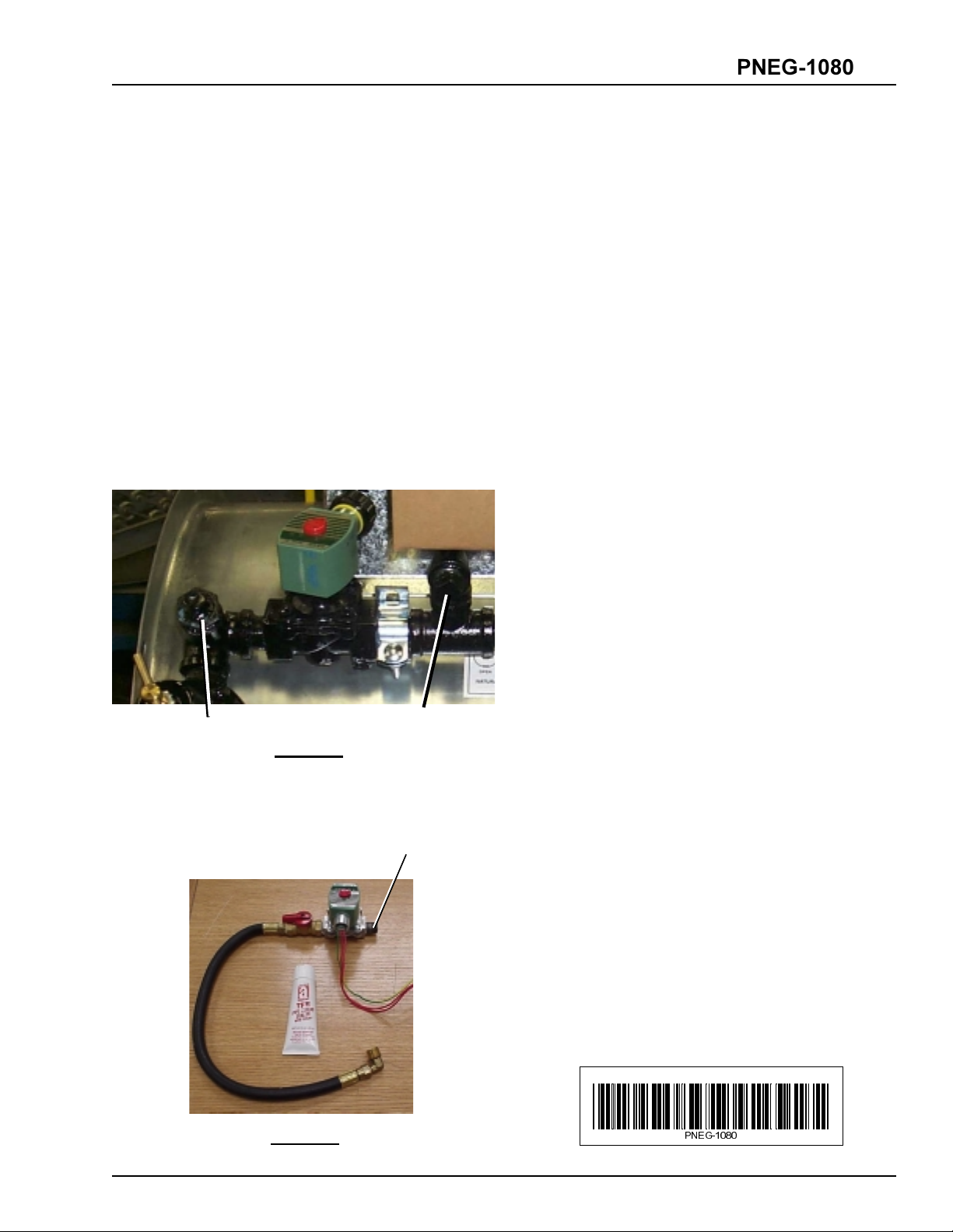
Plug A
Plug B
Photo 1
2. Remove TWO ½ NPT plugs from pipetrain on
heater. (Plugs A & B, Photo 1)
Close Nipple
3. Apply a sufficient amount of pipe thread sealer to
½ close nipple on outgoing side of solenoid valve
on HILO kit pipe train. (Photo 2)
4. Insert the Close Nipple (Photo 2) of the HILO
pipetrain into heater pipetrain where Plug B (Photo
1) was removed. Tighten HILO pipetrain securely to
heater pipetrain with a pipe wrench.
5. Apply pipe thread sealer to the ½ gas hose at the
opposite end of the HILO train.
6. Insert gas hose where Plug A (Photo 1) was removed
from the heater pipetrain. Tighten the hose securely
to the heater pipetrain.
7. Assemble conduit and fittings onto the solenoid valve
on the HILO pipe train.
8. Pull conduit and wires from solenoid up to control
box and mark where the hole location will be.
Photo 2
9. Drill a 7/8 hole in the control box at this location
and assemble conduit and wires through this hole.
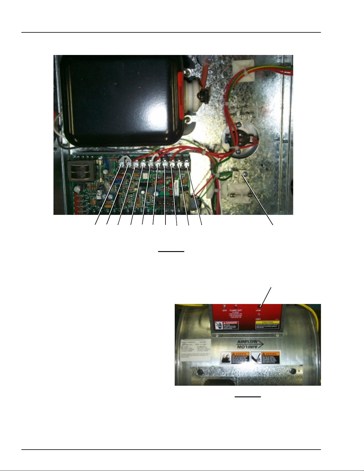
10. Remove solenoid wire from terminal 8 (Photo 3) on
the circuit board and move it to terminal 10 (Photo
3).
31(*
Page 2
HILO Kit Installation
PNEG-1080
Terminal: 1 2 3 4 5 6 7 8 9 10
Photo 3
11. Place one of the red wires from the solenoid on the
HILO pipetrain on terminal 8 (Photo 3) and the other
red wire from that solenoid to terminal 5 or 6 (Photo
3). Place the green wire from the solenoid into one of
the ground lugs located in the bottom of the control
box.
12. You will now need to remove the black hole plug
from the front of the control box located under the
main indicator light. (see Photo 4)
13. Insert the red light into this hole.
14. Connect one side of the light to terminal 10 (Photo 3)
with the black wire and .187 female slip on provided
in the kit. Connect the other side of the light to terminal 5 or 6 (Photo 3) with the white wire and .187
female slip on connector.
Ground Lug
Hole Plug
Photo 4
15. Your HILO kit is now installed. Be sure to check all
connections for secureness and check pipe train for
leaks.
 Loading...