

Page 1
PNEG-1079
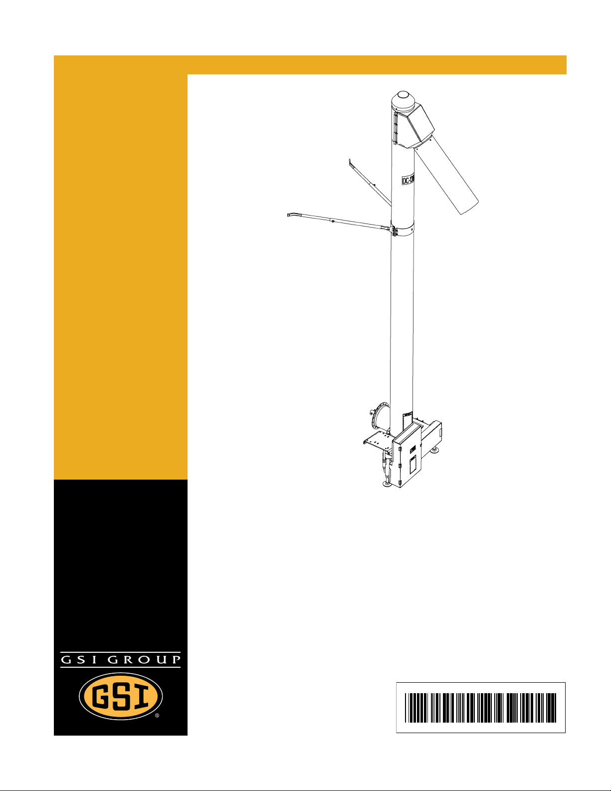
6", 8" and 10" Vertical Bin
Unload Auger
Assembly and Operation Manual
PNEG-1079
Date: 06-29-11
Page 2

Personnel operating or working around this equipment should read this manual. This manual
must be delivered with equipment to its owner. Failure to read this manual and its safety
instructions is a misuse of the equipment. Any misuse of the equipment may void the warranty.
2 PNEG-1079 6", 8" and 10" Vertical Bin Unload Auger
Page 3

Table of Contents
Contents
Chapter 1 Introduction ..........................................................................................................................................4
General Information .............................................................................................................................. 4
Capacity ................................................................................................................................................ 4
Chapter 2 Safety .....................................................................................................................................................5
Safety Guidelines .................................................................................................................................. 5
Operator Qualifications ....................................................................................... .... ... ... ... ..................... 7
Chapter 3 Safety Decals ........................................................................................................................................8
Chapter 4 Assembly Instructions ......................... .................................................... ..........................................12
Attaching Vertical to Bin ............................... .... ... ... ... .... ... ... .......................................... ... ................... 12
Electric Motor Drive ............................................................................................................................. 14
Vent Plug ............................................................................................................................................. 17
Chapter 5 Operation Procedures ........................................................................................................................18
Inspect the Auger ................................................................................................................................ 18
Designate a Work Area ....................................................................................................................... 18
Operating Procedures .................................. .... ... ... ... .... ... ... ... .... ... ... ................................................... 18
Break-In Period ................................................................................................................................... 19
PTO Drive ........................................................................................................................................... 19
Electric Motor Drive ............................................................................................................................. 20
Normal Shut Down .............................................................................................................................. 21
Intermittent Operation Shut Down ................................. ................................................... ................... 21
Emergency Shut Down .................................................... ... ... .... ... ... ... ... .... ... ... ................................... 21
Lock Out .............................................................................................................................................. 21
Capacity .............................................................................................................................................. 22
Clean-Up ............................................................................................................................................. 22
Storage Preparation ..................................... .... ... .......................................... ... ... .... ............................ 22
Lubrication and Maintenance .............................................................................................................. 22
Chapter 6 Troubleshooting .................................................................................................................................23
Chapter 7 Parts List .............................................................................................................................................25
6" Catalog Level Breakdown ............................................................................................................... 26
6" Spout with Extension ...................................................................................................................... 28
6" Spout with Band .............................................................................................................................. 29
6" Tube and Flight Assembly .............................................................................................................. 30
8" Catalog Level Breakdown ............................................................................................................... 32
8" Spout with Band and Extension ...................................................................................................... 34
8" Tube and Flight Assembly .............................................................................................................. 36
10" Catalog Level Breakdown ............................................................................................................. 38
10" Spout with Extension ................................................................. ... ... .... ... ... ... .... ... ......................... 40
10" Spout with Band ..... ... .... ... ... ... .... ... ... .......................................... ... ... ............................................. 41
10" Tube and Flight Assembly ...................................................................... ...................................... 42
Chapter 8 Warranty ..............................................................................................................................................45
PNEG-1079 6", 8" and 10" Vertical Bin Unload Auger 3
Page 4

1. Introduction
General Information
1. We reserve the right to improve our product whenever possible and practical to do so. We reserve
the right to change, improve and modify products at any time without obligation to make changes,
improvements and modifications on equipment sold previously.
2. The 6", 8" and 10" Vertical Bin Unload Augers have been designed and manufactured to give years
of dependable service. The care and maintenance of this machine will affect the satisfaction and
service obtained. By observing the instructions and suggestions we have recommended, the owner
should receive competent service for many years. If additional information or assistance should be
required, please contact the factory or the local dealer.
3. When receiving merchandise, it is important to check both the quantity of parts and their descriptions
with the packing list enclosed within each package. All claims for freight damage or shortage must
be made by the consignee within ten (10) days from the date of the occurrence of freight damage.
The consignee should accept the shipment after noting the damage or loss.
Capacity
1. The capacities may vary greatly under varying conditions. The following factors play a role in the
performance of the auger:
• Speed • Amounts of foreign matter
• Angle of operation • Different materials
• Moisture content • Methods of feeding
2. For example, a twenty-five percent (25%) moisture could cut capacity by as much as 40% under
some conditions.
4 PNEG-1079 6", 8" and 10" Vertical Bin Unload Auger
Page 5
2. Safety
DANGER
WARNING
CAUTION
NOTICE
This is the safety alert symbol. It is used to alert you
to potential personal injury hazards. Obey all safety
messages that follow this symbol to avoid possible
injury or death.
WARNING indicates a hazardous situation which, if not
avoided, could result in death or serious injury.
CAUTION, used with the safety alert symbol, indicates a
hazardous situation which, if not avoided, could result in
minor or moderate injury.
NOTICE is used to address practices not related to
personal injury.
DANGER indicates a hazardous situation which, if not
avoided, will result in death or serious injury.
Safety Guidelines
This manual contains information that is important for you, the owner/operator, to know and understand.
This information relates to protecting personal safety and preventing equipment problems. It is the
responsibility of the owner/operator to inform anyone operating or working in the area of this equipment of
these safety guidelines. To help you recognize this information, we use the symbols that are defined
below. Please read the manual and pay attention to these sections. Failure to read this manual and its
safety instructions is a misuse of the equipment and may lead to serious injury or death.
PNEG-1079 6", 8" and 10" Vertical Bin Unload Auger 5
Page 6

2. Safety
Operate Unload Equipment Properly
• Untrained operators subject themselves and others to SERIOUS INJURY
or DEATH. NEVER allow untrained personnel to operate this equipment.
• NEVER work alone.
• Keep children and other unqualified personnel out of the working
area at ALL times. Refer to the Start-Up section of this manual for
diagrams of the work area.
• Make sure ALL equipment is locked in position before operating.
• NEVER start equipment until ALL persons are clear of the work area.
• Keep hands and feet away from the auger intake and other moving parts.
• NEVER attempt to assist machinery operation or to remove trash from equipment while
in operation.
• Be sure all operators are adequately rested and prepared to perform all functions of operating
this equipment.
• NEVER allow any person intoxicated or under the influence of alcohol or drugs to operate
the equipment.
• Make sure someone is nearby who is aware of the proper shut down sequence in the event of an
accident or emergency.
• ALWAYS think before acting. NEVER act impulsively around the equipment.
• NEVER allow anyone inside a bin, truck or wagon which is being unloaded by an auger or
conveyor. Flowing grain can trap and suffocate in seconds.
• Use ample overhead lighting after sunset to light the work area.
• Keep area around intake free of obstacles such as electrical cords, blocks, etc., that might
trip workers.
• NEVER drive, stand or walk under the equipment.
• Use caution not to hit the auger when positioning the load.
• ALWAYS lock out ALL power to the equipment when finished unloading a bin.
• Be aware of pinch points. A pinch point is a narrow area between two surf aces that is likely to trap or
catch objects and so is a potential safety hazard.
Operate Unload
Equipment Safely
6 PNEG-1079 6", 8" and 10" Vertical Bin Unload Auger
Page 7

2. Safety
Operator Qualifications
A. The User/Operator must be competent and experienced to operate auger equipment. Anyone who
works with or around augers must have good common sense in order to be qualified. These persons
must also know and meet all other qualifications, such as:
i. Any person who has not read and/or does not understand all operation and safety procedures
is not qualified to operate any auger systems.
ii. Certain regulations apply to personnel operating power machinery. Personnel under the age of
18 years may not operate power machinery, including augers. It is your responsibility, as owner
and/or supervisor, to know what these regulations are in your area or situation.
iii. Unqualified or incompetent persons are to remain out of the work area.
iv. O.S.H.A. (Occupational Safety and Health Administration) regulations state: “At the time of
initial assignment and at least annually thereafter, the employer shall instruct every employee
in the safe operation and servicing of all equipment with which the employee is, or will be
involved”. (Federal Occupational Safety and Health Standards for Agriculture. Subpart D,
Section 1928.57 (a) (6)).
B. As a requirement of O.S.H.A., it is necessary for the employer to train the employee in the safe
operating and safety procedures for this auger. The sign-off sheet is provided for your convenience
and personal record keeping. All unqualified persons are to stay o ut o f the work area at all times. It
is strongly recommended that another qualified person who knows the shut down procedure is in the
area in the event of an emergency.
Date Employee Name Supervisor Name
PNEG-1079 6", 8" and 10" Vertical Bin Unload Auger 7
Page 8
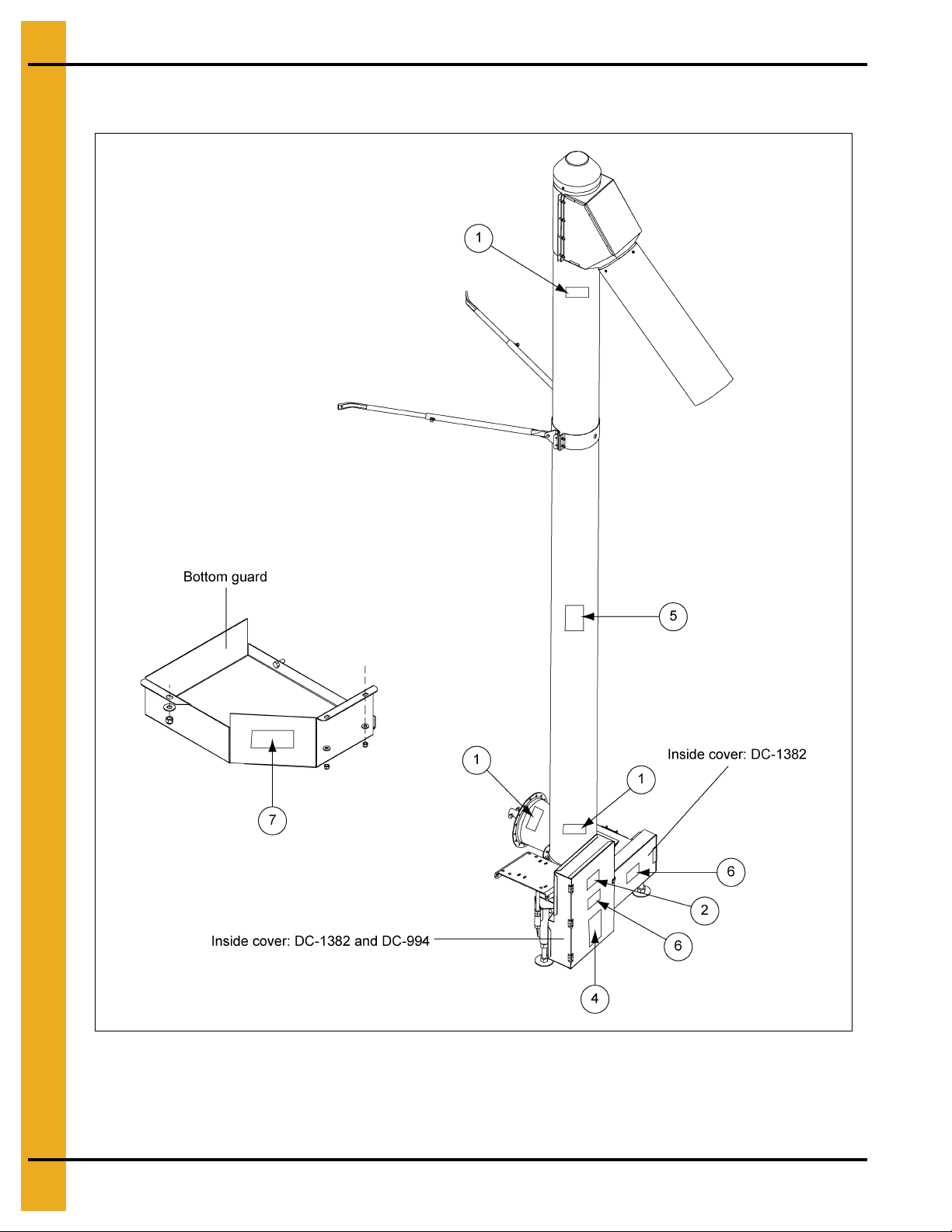
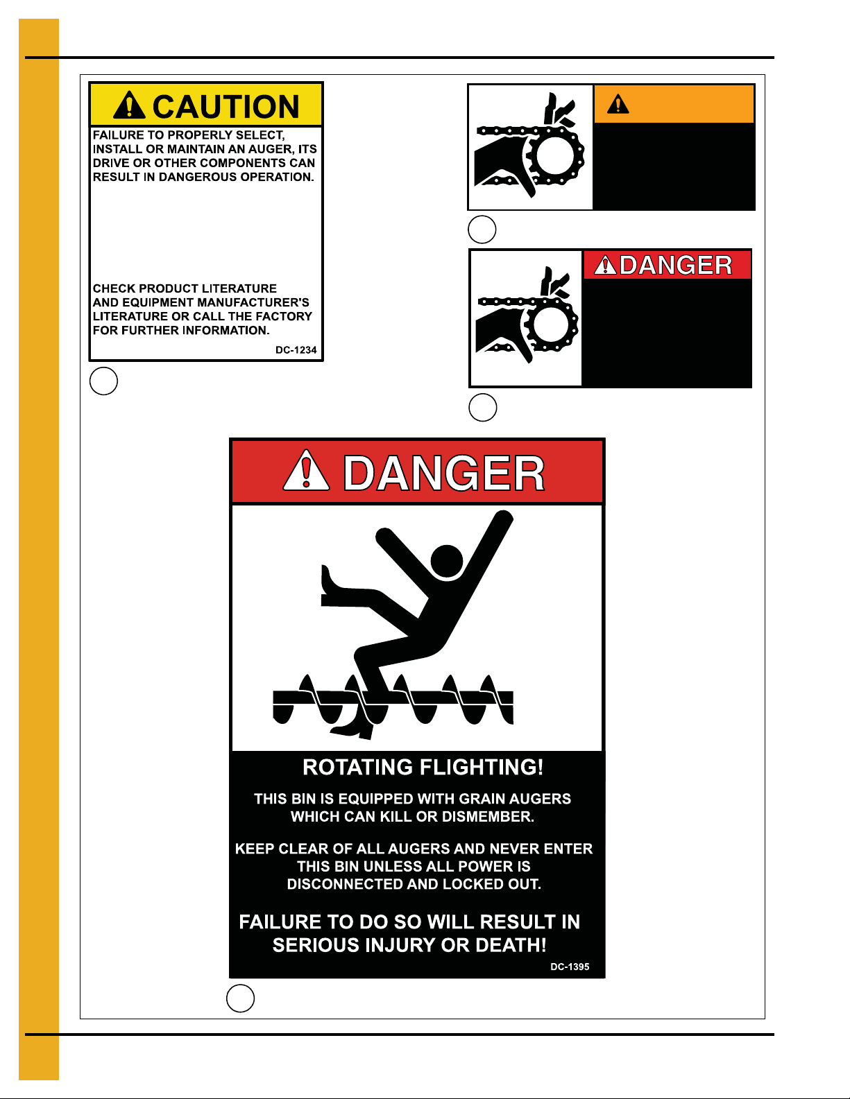
3. Safety Decals
The figure
Vertical Bin Unload Auger. Samples and explanations of these decals are shown
below
shows the location of the decals and safety signs which should appear on the Commercial
on Pages 9 and 10
.
NOTE: Please remember safety signs provide important safety information for people working near bin
unloading equipment that is in operation. Any safety signs that are worn, missing, illegible or
painted over should be replaced immediately. Obtain FREE replacements by contacting
the dealer.
8 PNEG-1079 6", 8" and 10" Vertical Bin Unload Auger
Page 9
3. Safety Decals
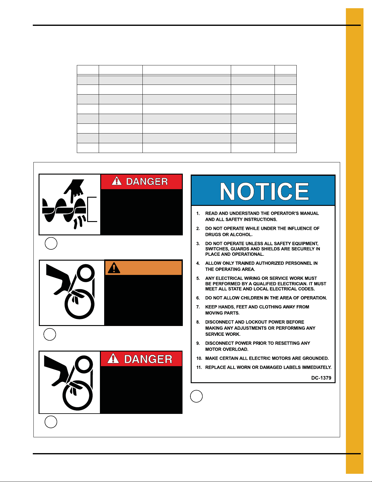
SHEAR POINT
Keep clear of rotating auger and
moving parts.
Do not remove or modify guards.
Disconnect and lock out power
before servicing.
Failure to do so will result in
serious INJURY or DEATH.
DC-1381
SHEAR POINT
Keep hands clear of moving
parts. Do not operate with
guard removed. Disconnect
and lockout power before
servicing.
DC-995
WARNING
SHEAR POINT
Keep hands clear of moving
parts. Do not operate with
guard removed. Disconnect
and lockout power before
servicing.
DC-994
1
2
3
4
The safety decals Chart below lists all the safety decals that should be included with the auger. Inspect all
decals and replace any that are illegible, worn or missing. Contact the dealer or the manufacturer to ord er
replacement decals.
Ref # Part # Description Size Qty
1 DC-1381 Danger - Shear Point (Auger) 4-1/2" x 2" 3
2 DC-995 Warning - Shear Point (Belt) 4-1/2" x 2" 1
3 DC-994 Danger - Shear Point (Belt) 4-1/2" x 2" 1
4 DC-1379 Notice 5-1/8" x 7-3/8" 1
5 DC-1234 Caution 2-1/4" x 2-3/4" 1
6 DC-1386 Warning - Shear Point (Chain) 4-1/2" x 2" 2
7 DC-1382 Danger - Shear Point (Chain) 4-1/2" x 2" 3
8 DC-1395 Danger - Rotating Flight (for bin) 4-1/4" x 6" 1
PNEG-1079 6", 8" and 10" Vertical Bin Unload Auger 9
Page 10
3. Safety Decals
5
7
6
8
THIS EQUIPMENT IF IMPROPERLY
SELECTED, INSTALLED OR
MAINTAINED MAY FAIL AND
COULD RESULT IN SERIOUS
INJURY OR PROPERTY DAMAGE.
WARNING
SHEAR POINT
Moving parts can
crush and cut. Keep
hands clear of
sprocket and chain.
SHEAR POINT
Moving parts can
crush and cut. Keep
hands clear of
sprocket and chain.
DC-1386
DC-1382
10 PNEG-1079 6", 8" and 10" Vertical Bin Unload Auger
Page 11
3. Safety Decals
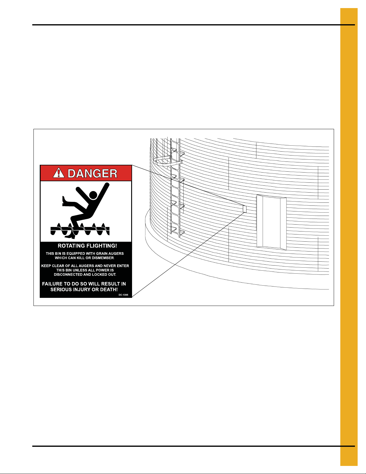
A. DANGER Sign No. DC-1395 was supplied with your bin unloading equipment. This safety sign
should be applied to the side of the bin near the bin opening, so it will be viewed by people
entering into the bin storage building. Do not cover any safety signs or any other signs that are
already there.
B. If the safety sign location suggested is not in full view because of equipment modifications, other
equipment in the area or any reason, then locate the safety sign in a more suitable location.
C. Be certain the surface is clean, dry and free of dirt and oil. Peel paper backing from decals and stick
into place. The adhesive backing will bond on contact.
NOTE: Please remember, safety signs provide important safety information for people working near bin
unloading equipment that is in operation.
NOTE: If the Safety Sign cannot be easily read for any reason or has been painted over, replace it
immediately. Additional Safety Signs may be obtained free of charge from your dealer, distributor
or ordered from the factory.
Order SAFETY SIGN NO. DC-1395
PNEG-1079 6", 8" and 10" Vertical Bin Unload Auger 11
Page 12
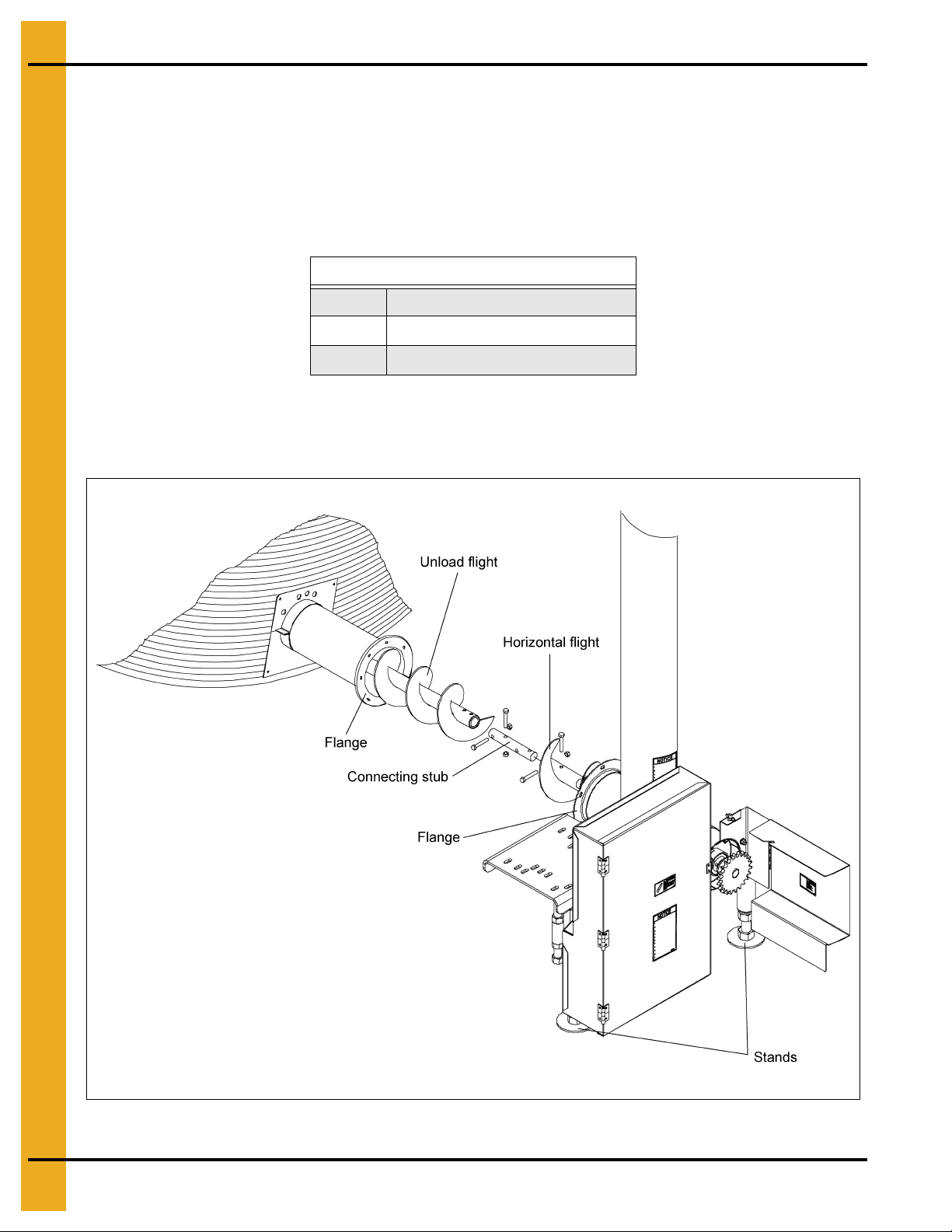
4. Assembly Instructions
Attaching Vertical to Bin
1. First, slide out enough bin unload flight to connect it to the connecting stub.
2. Attach the bin unloading flight and the horizontal flight to the connecting stub using two (2)
3/8" x 2" hex head cap screws for 6", two (2) 7/16" x 2-1/2" hex head cap screws for 8" or two (2)
1/2" x 3" hex head cap screws for 10" with lock nuts. (See Chart.) (See Cha rt on Page 20 for proper
bin unloading flight.)
Connecting Stub Bolts
6" Use Two (2) 3/8" x 2" Bolts
8" Use Two (2) 7/16" x 2-1/2" Bolts
10" Use Two (2) 1/2" x 3" Bolts
3. Slide bin unloading flight into unloading tube. With vertical auger in upright position, attach flanges
together using 5/16" x 3/4" bolts with hex nuts. (See Figure 4A below and Figure 4B on Page 13.)
4. Adjust stands so they hold the weight of the vertical auger. (See Figure 4A.)
Figure 4A 8" Shown
12 PNEG-1079 6", 8" and 10" Vertical Bin Unload Auger
Page 13
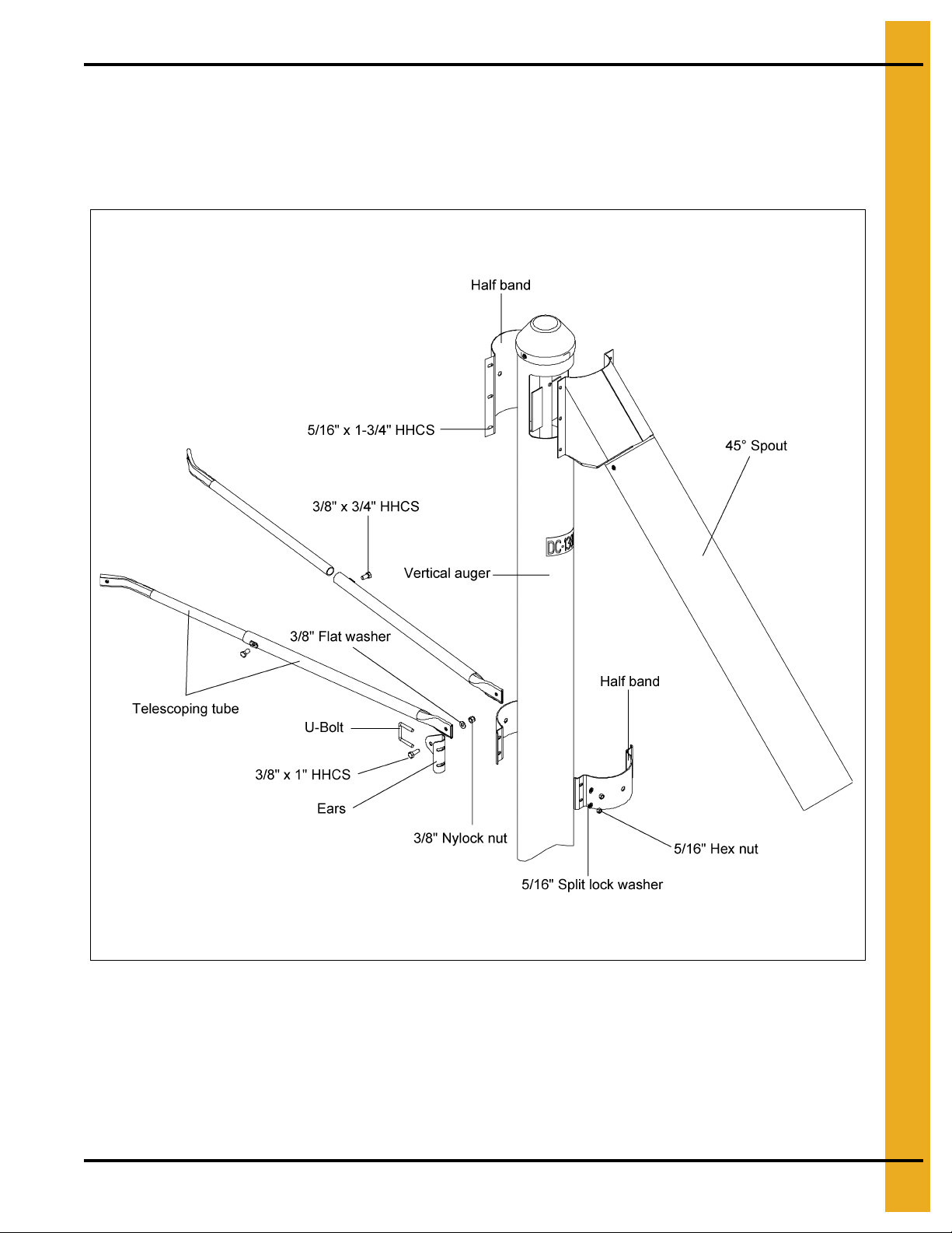
4. Assembly Instructions
Attaching Vertical to Bin (Continued)
5. Using the same U-bolts and nuts, attach ears and half band to vertical tube at the same. For maximum
stability, locate the bands on the upper half of the tube.
6. Bolt telescoping tubes to the ears using two (2) 3/8" x 1" bolts and nylock nuts. (See Figure 4B.)
(See Figure 4B.)
Figure 4B
7. Secure telescoping tube inside of tube at appropriate length with 3/8" x 3/4" hex head set screws.
8. Attach telescoping tube to bin structure. (Hardware not included.)
9. Assemble spout to vertical auger over discharge opening with half band using 5/16" x 1-3/4"
hex head cap screws and lock nuts.
PNEG-1079 6", 8" and 10" Vertical Bin Unload Auger 13
Page 14
4. Assembly Instructions
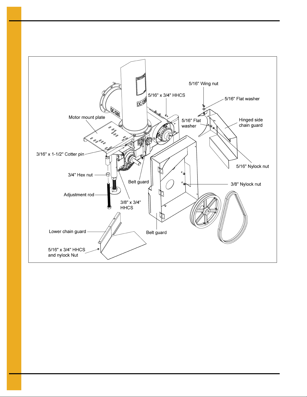
Electric Motor Drive
1. Assemble a 3/4" nut onto threaded adjustment rod. Then thread adjustment rod into the 3/4" nut that
is welded onto the sleeve of vertical. (See Figure 4C.)
Figure 4C 6" and 8" Vertical
2. Slide motor mount plate onto pivot rod weldment of vertical. Install cotter pin to hold motor mount
plate place.
3. Attach belt guard to belt guard mounting brackets with four (4) 3/8" x 3/4" long HHCS and nylon
lock nuts.
4. 6" and 8": Attach hinged side chain guard to vertical with two (2) 5/16" x 3/4" long HHCS,
flat washers and nylon lock nuts. Hold chain guard closed by using a 5/16" flat washer and
wing nut. (See Figure 4C.)
10":
Attach hinged side chain guard to vertical with two (2) 5/16" x 3/4" long HHCS, flat washers and
nylock nuts. Hold chain guard closed by attaching it to the lower chain guard using a 5/16" nylock nut.
(See Figure 4D on Page 15.)
14 PNEG-1079 6", 8" and 10" Vertical Bin Unload Auger
Page 15

Electric Motor Drive (Continued)
4. Assembly Instructions
Figure 4D 10" Vertical
5. 6" and 8": Bolt lower chain guard to underside of vertical using two (2) 5/16" x 3/4" long HHCS and
nylon lock nuts. (See Figure 4C on Page 14.)
10": Bolt lower chain guard to underside of vertical using one 3/8" x 1" HHCS flat washer and
3/8" nylock nut through the flange with one hole. On the flange with two (2) holes, use two (2)
1/4" x 3/4" HHCS, flat washers and nylock nuts. (See Figure 4D above and Figure 4E on Page 16.)
6. Assemble chain onto sprockets. Tighten the chain using the idler sprocket, which should be attached
with two (2) 5/8" x 2" HHCS, three (3) flat washers, one split lock washer and nylock nut. (The chain
should run underneath idler sprocket.) (See Figure 4F on Page 16.)
7. Install a 4-1/2" O.D. pulley for 6" and 8" models on motor and for 10" models use a 4" O.D. pulley on
motor. (This pulley not furnished.) Install 12" pulley on gearbox shaft as close to the sprocket as
possible that is already mounted there. Using the 1/4" square key, which should already be in place,
tighten set screws in pulleys. (See Figure 4C on Page 14 and Figure 4D.)
PNEG-1079 6", 8" and 10" Vertical Bin Unload Auger 15
Page 16

4. Assembly Instructions
Electric Motor Drive (Continued)
8. Install belts onto pulleys and tighten by using the adjustment rod to raise motor mount plate. Once
the belts are tight, use locking nut to secure adjustment rod in place.
Figure 4E Lower Chain Guard for 10"
Figure 4F Idler Sprocket
16 PNEG-1079 6", 8" and 10" Vertical Bin Unload Auger
Page 17

4. Assembly Instructions
Vent Plug
1. Remove solid plug that was installed for shipping purposes.
2. Install the 1/8" x 1/4" pipe bushing (GK4470) followed by the 1/8"-27 7.5 PSI-15 PSI vent plug
(GK2697). (See Figure 4G.)
Figure 4G Vent Plug
PNEG-1079 6", 8" and 10" Vertical Bin Unload Auger 17
Page 18

5. Operation Procedures
Under no circumstances should persons not involved in the operation be
allowed to trespass into the work area.
WARNING
It shall be the duty of all operators to see that children and/or other persons stay
out of the work area. If anyone not involved in the actual operation trespasses
into the work area, it shall result in an immediate shut down by the operator.
WARNING
It shall be the responsibility of all operators to see that the work area has secure
footing, is clean and free of all debris and tools which might cause accidental
tripping and/or falling.
DANGER
Make certain everyone is clear before operating equipment.
WARNING
The operator shall be aware of any unusual vibrations, noises and the loosening
of any fasteners.
CAUTION
Keep all safety shields and devices in place.
DANGER
Keep hands, feet and clothing away from moving parts
DANGER
Shut off and lock out power to adjust, service or clean.
DANGER
Inspect the Auger
After delivery of the new auger and/or completion of assembly and before each use, inspection of the
machine is mandatory. This inspection should include, but not be limited to:
1. Check to see that all guards listed in the assembly instructions are secured in place and functional.
2. Check all safety signs and replace any that are worn, missing or illegible. They are listed in the front
in the decal section on Pages 9 and 1 0 of this manual. Safety signs may be obtained from the dealer
or ordered from the factory.
3. Check to see if all the fasteners are tight.
Designate a Work Area
Designate a large perimeter around the auger for a work area.
Operating Procedures
During the operation of the auger, one person shall be in a position to monitor the operation. Inspect the
drive before adding power and know how to shut down in an emergency. (See Page 19.) Visually inspect
the auger periodically during operation. For efficient and safe operation, be aware of all the adjustments
and checks which should be performed.
18 PNEG-1079 6", 8" and 10" Vertical Bin Unload Auger
Page 19

5. Operation Procedures
Before operating the unit, add #90 weight non-foaming oil to the gearbox until it
reaches the level check plug in the side of the gearbox.
CAUTION
CAUTION
Before starting the tractor, be certain power to PTO is OFF.
NOTICE
Be certain that the PTO driveline is securely attached to the auger and the tractor.
CAUTION
Use a PTO driveline with a rotating shield in good working order th at can be turned
freely on the shaft.
NOTICE
Align PTO driveline w ith tra cto r.
The auger may be operated at speeds from 500 RPM-750 RPM. Operating spe eds of 650 RPM-730 RPM
are recommended to achieve rated capacity. Auger flight speed in excess of recommended speed causes
excessive wear. Do not attempt full load operation at speeds below 350 RPM as high torque requirements
may damage the auger.
Break-In Period
Any screw conveyor when it is new or after it sets idle for a season should go through a “break-in” period.
The auger should be run at partial capacity until several hundred bushels of grain have been augered. This
polishes the flighting assembly and tube. Once this is accomplished, the auger can be operated at full
capacity. The auger should not be operated empty except at start-up and during clean-out.
PTO Drive
Only use a tractor with 540 RPM power take-off. If the tractor output PTO shaft is operated at 540 RPM,
the auger will have a 540 RPM auger flight speed.
NOTE: The PTO driveline furnished with the auger is equipped with a “SPRING-LOCK” coupler at the
tractor end. This type coupler is spring loaded and will fit the standard 1-3/8" x 6" spline PTO
output shaft from a tractor.
The retaining balls of the coupler lock into the ring groove of the tractor PTO output shaft to prevent
inadvertent detachment. The PTO driveline is a pin stop-type; that is, the two (2) telescoping sections will
not separate. It is a good practice to operate the PTO driveline in as short a configuration as possible and
keep in line with the tractor as much as possible during operation.
Double check the following before adding power:
Engage PTO at a slow RPM to minimize shock loads. Then work up RPM to recommend speed.
Never operate the auger empty for any length of time, as excessive wear will result. If at all possible,
do not stop or start the auger under load, especially before the flight and tube have become well polished,
as this may cause the auger to “freeze-up”. (See break-in period above.)
PNEG-1079 6", 8" and 10" Vertical Bin Unload Auger 19
Page 20

5. Operation Procedures
Reset and motor starting controls must be located so that the operator has full
view of the entire operation. A main power disconnect switch capable of being
locked only in the OFF position shall be provided. This shall be locked
whenever servicing or adjusting the auger.
DANGER
Disconnect power before resetting motor overloads. Make certain electric motor
is grounded.
DANGER
To Start Auger
1. Before starting the tractor, be certain power to PTO is OFF.
2. Start tractor.
3. Engage PTO at a slow RPM to minimize shock loads. Then work up RPM to recommended speed.
To Stop Auger
1. Let auger empty of grain before stopping.
2. Disengage PTO and lock out.
Electric Motor Drive
Use a 1750 RPM motor with HP as suggested in the Chart below. Electric motors and controls shall be
installed by a qualified electrician and must meet the standards set by the National Electrical Code and all
local and state codes. Use a 4-1/2" motor pulley (not furnished) for 650 RPM flight speed (6" and 8").
Use a 4" motor pulley for 580 RPM flight speed (10").
A magnetic starter should be used to protect the motor when starting and stopping. It should stop the motor
in case of power interruption, conductor fault, low voltage, circuit interruption or motor overload. Then the
motor must be restarted manually. Some motors have built-in thermal overload protection. If this type
motor is used, use only one with manual reset.
The horsepower recommendations are based on clean, dry shelled corn or wheat. High moisture grain
(above 15%) will require greater power. The maximum possible capacity will be less with high moisture
grain than with dry grain.
Horizontal Flight and Horsepower Required
Bin Diameter
14'-16' 8'-9" 8'-10" - 3" 7-1/2" 17'-19' 10'-9" 10'-10" - 3" 7-1/2" 20'-22' 11'-9" 11'-10" - 5" 7-1/2" 23'-25' 13'-3" 13'-4" 13'-6" 5" 7-1/2" 10"
26'-28' 14'-9" 14'-10" 15'-0" 5" 7-1/2" 10"
29'-31' 16'-3" 16'-4" 16'-6" 5" 7-1/2" 10"
32'-34' 18'-3" 18'-4" 18'-0" 7-1/2" 10" 15"
35'-37' 19'-3" 19'-4" 19'-6" 7-1/2" 10" 15"
NOTE: For higher moisture grain (up to 25%) the next larger motor may be used as a maximum.
Horizontal Flight Length Vertical Horsepower
6" 8" 10" 6" 8" 10"
Never operate the auger empty for any length of time as excessive wear will result. If at all possible, do
not stop or start the auger under load, especially before the flight and tube become well polished, as this
may cause the auger to “freeze-up”. (See break-in information on Page 19.)
20 PNEG-1079 6", 8" and 10" Vertical Bin Unload Auger
Page 21

5. Operation Procedures
Whenever you must service or adjust the equipment, make sure to stop motor
and lock out the power source.
DANGER
If the operator must leave the work area or whenever servicing or adjusting, the
unloading auger must be stopped and the power source locked out. Precautions
should be made to prevent anyone from operating the auger when the operator
is absent from the work area.
WARNING
Check the Following before Adding Power
1. Double check to make sure the guards are secured in place and functional.
To Start Auger
1. Start electric motor before conveying grain.
To Stop Auger
1. Let auger empty of grain before stopping.
2. Shut off electric motor and lock out.
Normal Shut Down
Make certain that the auger is empty before stopping the unit. Before the operator leaves the work area,
the power source shall be locked out. (See Lock Out below.)
Intermittent Operation Shut Down
When an auger is stopped and restarted under full load, it may result in damage to the auger. Therefore,
if intermittent operation is to be carried out, it is advisable to reduce the load level. When kept from
absolute filling, auger start-up is easier and operation is more efficient.
Emergency Shut Down
Should the auger be immediately shut down under load, first disconnect and lock out all power source.
Clear as much grain from the auger as you can using the clean-out doors. Never attempt to restart auger
when full.
NOTE: Starting the unit under load may result in damage to the auger. Such damage is considered
abuse of the equipment. When as much grain as possible has been cleared, reconnect power
source and clear auger gradually.
Lock Out
PTO Drive: Remove ignition key or coil wire from power source. (If this is impossible, remove
the PTO driveline from the work area.)
Electric Motor Drive: Use a main disconnect switch capable of being locked only in the OFF position.
PNEG-1079 6", 8" and 10" Vertical Bin Unload Auger 21
Page 22

5. Operation Procedures
Never clean, adjust or lubricate a machine that is in operation.
DANGER
Capacity
The results or capacities of screw conveyors or augers can vary greatly under diverse conditions. Different
materials, moisture content, amounts of foreign matter, angle of operation, methods of feeding and speed
all play a role in performance of the auger. Capacities listing in the Chart below will be achieved when
augering reasonably dry grain. Maximum possible capacity will be less with high moisture grain (above
15%) than with dry grain.
Unit Capacity BPH
6" 850-1250
8" 2000-2500
10" 3250-3750
Clean-Up
1. Check to see that all guards listed in the assembly instructions are in place and secured
and functional.
2. Check all safety decals and replaced any that are worn, missing or illegible. The safety decals are
listed on Pages 9 and 10. Safety decals may be obtained free of charge from the dealer or ordered
from the factory.
3. Check to see that all fasteners are securely in place.
Storage Preparation
1. Close all wells to discharge tube.
2. Be sure the unload tube is empty.
3. Make sure power source is disconnected and locked out.
4. Check to see that all fasteners are secure.
Lubrication and Maintenance
The flange bearing on the head and tail ends of the auger should be lubricated at frequent intervals.
Check belt tension on motor drive belts for electric drive units.
Lubricate and check drive chain at frequent intervals. Adjust chain tension, if necessary.
Check to make sure all guards are in place.
22 PNEG-1079 6", 8" and 10" Vertical Bin Unload Auger
Page 23

6. Troubleshooting
Troubleshooting Guide
Problem Possible Cause Solution
The auger
is vibrating.
Capacity is
too low.
The auger plugs.
1. Damage can occur to the auger flighting, causing
noise. Damage usually is caused from foreign
material being run through the auger.
2. Drive belt may be overtightened, putting head
stub and flight in a bind.
1. There may not be enough grain reaching
the auger.
2. The auger is moving too slowly.
1. The auger may be “jamming” because too much
grain is reaching the auger.
2. The grain may be wet.
3. The auger may be jammed with foreign material. 3. Remove any foreign material in the auger.
4. The motor may be to small or wired incorrectly.
1. It may be necessary to remove the flighting
for inspection.
2. Loosen the drive belts.
1. Make sure the intake has not bridged
over, restricting flow. The flighting at the
intake should be covered with grain for
maximum capacity.
2. Check the auger speed. Low capacity will
result from speeds slower than recommended.
1. Use the control gates to decrease the amount
of grain the auger is gathering.
2. If wet grain or other hard-to-move material is
being augered, use a larger size motor than
recommended for normal use.
4. Check wiring or consider using the next larger
size motor.
PNEG-1079 6", 8" and 10" Vertical Bin Unload Auger 23
Page 24

NOTES
24 PNEG-1079 6", 8" and 10" Vertical Bin Unload Auger
Page 25

1. 6" Catalog Level Breakdown
2. 6" Spout with Extension
3. 6" Spout with Band
4. 6" Tube and Flight Assembly
5. 8" Catalog Level Breakdown
6. 8" Spout with Band and Extension
7. 8" Tube and Flight Assembly
8. 10" Catalog Level Breakdown
9. 10" Spout with Extension
10. 10" Spout with Band
7. Parts List
11. 10" Tube and Flight Assembly
PNEG-1079 6", 8" and 10" Vertical Bin Unload Auger 25
Page 26

7. Parts List
6" Catalog Level Breakdown
26 PNEG-1079 6", 8" and 10" Vertical Bin Unload Auger
Page 27

6" Catalog Level Breakdown Parts List
Ref # Part # Description
1 GK5093 6" Vertical Tube and Flight Assembly
2 GK1043 45° Spout with 3' Extension
3 GK1122 4" 12 Gauge Half Band
4 GK1034 Adjustable Mounting Ear
5 GK1892 Telescoping Outer Leg
6 GK1891 Telescoping Inner Leg
7 GK1321 2 Groove, 12" O.D., 1" I.D. Sheave
8 GC06680 V-Belt, BX-48
9 GK4907 Motor Mount Plate
10 GK4914 #50 Roller Chain, 66 Pitch with Connecting Link
11 GK4915 Horizontal Chain Guard
12 GK5726 Adjustment Screw
7. Parts List
13 GK4931 Bottom Chain Guard
14 GK6471 Belt Guard
15 GK4470 1/8"-27 NPT x 1/4"-18 NPT Pipe Bushing
16 GK2697 1/8" -2 7 N PT Vent Plug, 7-1/2 - 15 PSI
17 S-7079 5/16"-18 x 1-3/4" U-Bolt
18 S-1147 5/16" Split Lock Washer Zinc
19 S-396 5/16"-18 Hex Nut YDP Grade 2
20 S-7469 3/8"-16 x 1" HHCS Zinc Grade 5
21 S-248 3/8" Flat Washer YDP
22 S-7383 3/8"-16 Nylon Lock Nut
23 S-7105 3/8"-16 x 3/4" HHCS Grade 5
24 S-234 3/4"-10 Hex Nut Zinc Grade 5
25 S-8312 3/16" x 1-1/2" Cotter Pin Zinc
26 S-4275 5/16"-18 x 3/4" HHTB Zinc Grade 5
27 S-845 5/16" Flat Washer YDP Grade 2
28 S-7382 5/16"-18 Nylon Lock Nut Zinc Grade 5
29 S-4301 5/16"-18 Wing Nut Zinc Grade 2
PNEG-1079 6", 8" and 10" Vertical Bin Unload Auger 27
Page 28

7. Parts List
6" Spout with Extension
6" Spout with Extension Parts List
Ref # Part # Description
1 GK1124 6" x 42" 16 Gauge Galvanized Tube
2 GK2421 6" 45° Spout with Band
3 S-6497 1/4" x 3/4" Self-Tapping Screw Zinc
28 PNEG-1079 6", 8" and 10" Vertical Bin Unload Auger
Page 29

6" Spout with Band
7. Parts List
6" Spout with Band Parts List
Ref # Part # Description
1 GK11 23 6" 45° Spout
2 GK11 25 6" x 10" 16 Gauge Half Band
3 S-2741 5/16"-18 x 1-1/2" HHCS Zinc Grade 5
4 S-7382 5/16"-18 Nylon Lock Nut Zinc Grade 5
PNEG-1079 6", 8" and 10" Vertical Bin Unload Auger 29
Page 30

7. Parts List
6" Tube and Flight Assembly
30 PNEG-1079 6", 8" and 10" Vertical Bin Unload Auger
Page 31

7. Parts List
6" Tube and Flight Assembly Parts List
Ref # Part # Description Ref # Part # Description
1 GK4905 Vertical Cross Welded Assembly 31 S-3611 5/16"-18 Serrated Flange Nut YDP Grade 2
2 S-2071 3/8"-16 x 1-1/4" HHCS Zinc Grade 5 32 DC-1234 Decal, Caution 2-1/4" x 2-3/4"
3 GK1049
4 S-7383 3/8"-16 Nylon Lock Nut 34 GK4912 Horizontal Bearing Plate
5 GK491 1 Chain Tightening Mount 35 S-8234 7/16"-14 Nylon Lock Nut Zinc Grade 2
6 S-858 5/8" Flat Washer Zinc Grade 2 36 S-4275 5/16"-18 x 3/4" HHTB Zinc Grade 5
7 GK1701
8 S-8399 5/8"-11 x 2" HHTB Zinc Grade 5 38 GK1116 1" O.D. x 7-7/8" Drive Shaft
9 S-3208 5/8" Split Lock Washer Zinc 39 GK1351 1" O.D. x 9-19/32" Connecting Shaft
10 S-4110 5/8"-11 Hex Nut Zinc Grade 5 40 GK10071 Gearbox, 1:1
11 S-7149 5/16"-18 x 1-3/4" HHTB Zinc Grade 5 41 S-1054 3/8" Split Lock Washer Zi n c
12 S-1147 5/16" Split Lock Washer Zinc 42 S-7105 3/8"-16 x 3/4" HHCS Grade 5
13 S-396 5/16"-18 Hex Nut YDP Grade 2 43 GK4913 Belt Guard Mount Bracket
14 S-1196 5/16"-18 x 1" HHCS Zinc Grade 5 44 S-248 3/8" Flat Washer YDP
15 S-7382 5/16"-18 Nylon Lock Nut Zinc Grade 5 45 S-7469 3/8"-16 x 1" HHCS Zinc Grade 5
16 GK5068 Vertical Tube 46 GK4910 Support Stand
17 S-845 5/16" Flat Washer YDP Grade 2 47 S-240 1"-8 Hex Nut Zinc Grade 5
1" 2 Hole Flange Bearing with
Lock Collar
#50 Idler Sprocket with Bearing,
13 Tooth, 5/8" Bore
33 DC-1381 Decal, Auger Danger 2" x 4-1/2"
37 GK2180 Horizontal Flight Welded Assembly
18 GK4904 1" O.D. x 8-1/16" Drive Stub 48 GK4908 Support Foot
19 GK4903 Vertical Flight Welded Assembly 49 GK4906 Motor Mount Plate Pivot
20 S-3727 3/8"-16 x 1-3/4" HHCS YDP Grade 8 50 S-456 3/8"-16 Hex Nut YDP Grade 5
21 S-8251 3/8"-16 Stover Nut Zinc Grade C 51 GK4917 Tension Arm Mount
22 GK1117 1" O.D. x 7" Intake Shaft 52 S-6995 3/8"-16 x 2-1/2" Carriage Bolt Zinc Grade 5
23 GK7929 Vertical Bearing Plate 53 GK1014 #50 Sprocket, 15 Tooth, 1" Bore
24 S-3886 7/16"-14 x 1-1/4" HHCS Zinc Grade 5 54 GK7867
25 S-7014 7/16" Split Lock Washe r Zinc 55 GK4918 Idler Tension Arm
26 S-7332 7/16"-14 Hex Nut YDP Grade 5 56 S-6494 5/8"-11 Deformed Lo ck Nut Zinc Grade 5
27 GK1115 Vert ical Cap 57 GK1704 5" x 1/16" Pitch Return Spring Zinc
28 GC12223 Cap Bracket 58 S-9168 1/4" Square x 1" Key
29 S-1429 1/4"-20 x 3/4" HHCS Zinc Grade 2 59 S-8679 1/4" Square x 4" Key
30 S-7025 1/4"-20 Nylon Lock Nut 60 GK1110 #50 Sprocket, 22 Tooth, 1" Bore
#50 Roller Chain, 41 Pitch with
Connecting Link
PNEG-1079 6", 8" and 10" Vertical Bin Unload Auger 31
Page 32

7. Parts List
8" Catalog Level Breakdown
32 PNEG-1079 6", 8" and 10" Vertical Bin Unload Auger
Page 33

8" Catalog Level Breakdown Parts List
Ref # Part # Description
1 GK5210 8" Vertical Tube and Flight Assembly
2 GK1002 45° Spout with 3'-8" Extension
3 GK1059 4" 12 Gauge Half Band
4 GK1034 Adjustable Mounting Ear
5 GK1892 Telescoping Outer Leg
6 GK1891 Telescoping Inner Leg
7 GK4932 Bottom Chain Guard
8 GK6471 Belt Guard
9 GK1024 #50 Roller Chain, 69 Pitch with Connecting Link
10 GK4925 Hori zontal Chain Guard
11 GK1321 2 Groove, 12" O.D., 1" I.D. Sheave
7. Parts List
12 GK4907 Motor Mount Plate
13 GK5726 Adjustment Screw
14 GC06637 V-Belt, BX-51
15 S-7079 5/16"-18 x 1-3/4" U-Bolt
16 S-396 5/16"-18 Hex Nut YDP Grade 2
17 S-7469 3/8"-16 x 1" HHCS Zinc Grade 5
18 S-7383 3/8"-16 Nylon Lock Nut
19 S-7105 3/8"-16 x 3/4" HHCS Grade 5
20 S-4275 5/16"-18 x 3/4" HHTB Zinc Grade 5
21 S-7382 5/16"-18 Nylon Lock Nut Zinc Grade 5
22 S-845 5/16" Flat Washer YDP Grade 2
23 S-234 3/4"-10 Hex Nut Zinc Grade 5
24 S-8312 3/16" x 1-1/2" Cotter Pin Zinc
25 S-4301 5/16"-18 Wing Nut Zinc Grade 2
26 GK4470 1/8"-27 NPT x 1/4"-18 NPT Pipe Bushing
27 GK2697 1/8" -2 7 N PT Vent Plug, 7-1/2 - 15 PSI
PNEG-1079 6", 8" and 10" Vertical Bin Unload Auger 33
Page 34

7. Parts List
8" Spout with Band and Extension
8" Spout with Band and Extension Parts List
Ref # Part # Description
1 GK6509 8" 45° Spout
2 GK1039 8" x 44" 14 Gauge Galvanized Tube
3 GK1505 8" x 14" 14 Gauge Half Band
4 S-6497 1/4" x 3/4" Self-Tapping Screw Zinc
5 S-2741 5/16"-18 x 1-1/2" HHCS Zinc Grade 5
6 S-7382 5/16"-18 Nylon Lock Nut Zinc Grade 5
34 PNEG-1079 6", 8" and 10" Vertical Bin Unload Auger
Page 35

NOTES
PNEG-1079 6", 8" and 10" Vertical Bin Unload Auger 35
Page 36

7. Parts List
8" Tube and Flight Assembly
36 PNEG-1079 6", 8" and 10" Vertical Bin Unload Auger
Page 37

7. Parts List
8" Tube and Flight Assembly Parts List
Ref # Part # Description Ref # Part # Description
1 GK4922 Vertical Cross Welded Assembly 31 S-3611 5/16"-18 Serrated Flange Nut YDP Grade 2
2 S-7528 1/2"-13 x 1-1/2" HHCS Zinc Grade 2 32 DC-1234 Decal, Caution 2-1/4" x 2-3/ 4 "
3 GK1017
4 S-236 1/2" Split Lock Washer Zinc 34 GK4924 Horizontal Bearing Plate
5 S-3729 1/2"-13 Hex Nut YDP Grade 5 35 S-7469 3/8"-16 x 1" HHCS Zinc Grade 5
6 GK4923 Chain Tightening Mount 36 S-248 3 /8" Flat Washer YDP
7 S-1196 5/16"-18 x 1" HHCS Zinc Grade 5 37 S-7383 3/8"-16 Nylon Lock Nut
8 S-7382 5/16"-18 Nylon Lock Nut Zinc Grade 5 38 GK1005 Horizontal Flight Welded Assembly
9 S-7149 5/16"-18 x 1-3/4" HHTB Zinc Grade 5 39 GK1328 1-1/4" O.D. x 9-1/2" Connecting Shaft
10 S-1147 5/16" Split Lock Washer Zinc 40 GK10071 Gearbox, 1:1
11 S-396 5/16"-18 Hex Nut YDP Grade 2 41 GK4910 Support Stand
12 S-858 5/8" Flat Washer Zinc Grade 2 42 S-1054 3/8" S p li t Lock Washer Zinc
13 GK1701
14 S-8399 5/8"-11 x 2" HHTB Zinc Grade 5 44 GK4913 Belt Guard Mount Bracket
15 S-3208 5/8" Split Lock Washer Zinc 45 S-240 1"-8 Hex Nut Zinc Grade 5
16 S-4110 5/8"-11 Hex Nut Zinc Grade 5 46 GK4908 Support Foot
17 GK5069 Vertical Tube 47 GK4906 Motor Mount Plate Pivot
1-1/4" 4 Hole Flange Bearing with
Lock Collar
#50 Idler Sprocket with Bearing,
13 Tooth, 5/8" Bore
33 DC-1381 Decal, Auger Danger 2" x 4-1/2"
43 S-7105 3/8"-16 x 3/4" HHCS Grade 5
18 S-845 5/16" Flat Washer YDP Grade 2 48 GK4927 #50 Sprocket, 19 Tooth, 1" Bore
19 GK4920 Vertical Flight Welded Assembly 49 GK4928 #50 Sprocket, 19 Tooth, 1-1/4" Bore
20 GK1018 1-1/4" O.D. x 9-1/4" Drive Shaft 50 GK4929
21 S-8316 7/16"-14 x 3" HHCS YDP Grade 8 51 GK4917 Tension Arm Mount
22 S-8317 7/16"-14 Stover Nut Zinc Grade C 52 GK4918 Idler Tension Arm
23 GK1012 1-1/4" O.D. x 6-3/4" Intake Shaft 53 S-6995 3/8"-16 x 2-1/2" Carriage Bolt Zinc Grade 5
24 GK7401 Vertical Bearing Plate 54 S-6494 5/8"-11 Deformed Lock Nut Zinc Grade 5
25 S-8760 1/2"-13 x 1-1/2" HHCS Zinc Grade 5 55 GK1704 5" x 1/16" Pitch Return Spring Zinc
26 GK1330
27 GK1011 Vertical Cap 57 GK1022 #50 Sprocket, 22 Tooth, 1-1/4" Bore
28 GC12223 Cap Bracket 58 GK1014 #50 Sprocket, 15 Tooth, 1" Bore
29 S-1429 1/4"-20 x 3/4" HHCS Zinc Grade 2
30 S-7025 1/4"-20 Nylon Lock Nut
1-1/4" 2 Hole Flange Bearing with
Lock Collar
56 S-9168 1/4" Square x 1" Key
59 S-8679 1/4" Square x 4" Key
#50 Roller Chain, 45 Pitch with
Connecting Link
PNEG-1079 6", 8" and 10" Vertical Bin Unload Auger 37
Page 38

7. Parts List
10" Catalog Level Breakdown
38 PNEG-1079 6", 8" and 10" Vertical Bin Unload Auger
Page 39

10" Catalog Level Breakdown Parts List
Ref # Part # Description
1 GK5274 10" Vertical Tube and Flight Assembly
2 GK1875 45° Spout with 3' Extension
3 GK1301 4" 12 Gauge Half Band
4 GK1034 Adjustable Mounting Ear
5 GK1892 Telescoping Outer Leg
6 GK1891 Telescoping Inner Leg
7 GK4948 Bottom Chain Guard
8 GK4945 Horizontal Chain Guard
9 GK4938 Motor Mount Plate
10 GK5726 Adjustment Screw
11 GK6471 Belt Guard
7. Parts List
12 GK4944 #60 Roller Chain, 70 Pitch
13 GK2332 3 Groove, 12" O.D., 1-1/4" I.D. Sheave
14 GC06337 V-Belt, BX-51
15 S-7079 5/16"-18 x 1-3/4" U-Bolt
16 S-7382 5/16"-18 Nylon Lock Nut Zinc Grade 5
17 S-396 5/16"-18 Hex Nut YDP Grade 2
18 S-7469 3/8"-16 x 1" HHCS Zinc Grade 5
19 S-248 3/8" Flat Washer YDP
20 S-7383 3/8"-16 Nylon Lock Nut
21 S-7105 3/8"-16 x 3/4" HHCS Grade 5
22 S-8244 1/4"-20 x 3/4" HHCS Zinc Grade 5
23 S-1430 1/4" Flat Washer Zinc Grade 2
24 S-7025 1/4"-20 Nylon Lock Nut
25 S-4275 5/16"-18 x 3/4" HHTB Zinc Grade 5
26 S-845 5/16" Flat Washer YDP Grade 2
27 S-8312 3/16" x 1-1/2" Cotter Pin Zinc
28 S-234 3/4"-10 Hex Nut Zinc Grade 5
PNEG-1079 6", 8" and 10" Vertical Bin Unload Auger 39
Page 40

7. Parts List
10" Spout with Extension
10" Spout with Extension Parts List
Ref # Part # Description
1 GK3386 10" 45° Spout with Band
2 GK1885 10" x 36" 12 Gauge Galvanized Tube
3 S-7229 1/4" x 1" Self-Tapping Screw Zinc
40 PNEG-1079 6", 8" and 10" Vertical Bin Unload Auger
Page 41

10" Spout with Band
7. Parts List
10" Spout with Band Parts List
Ref # Part # Description
1 GK1881 10" 45° Spout
2 GK2333 10" x 18" 14 Gauge Half Band
3 S-2741 5/16"-18 x 1-1/2" HHCS Zinc Grade 5
4 S-7382 5/16"-18 Nylon Lock Nut Zinc Grade 5
PNEG-1079 6", 8" and 10" Vertical Bin Unload Auger 41
Page 42

7. Parts List
10" Tube and Flight Assembly
42 PNEG-1079 6", 8" and 10" Vertical Bin Unload Auger
Page 43

7. Parts List
10" Tube and Flight Assembly Parts List
Ref # Part # Description Ref # Part # Description
1 GK4936 Vertical Cross Welded Assembly 33 DC-1381 Decal, Auger Danger 2" x 4-1/2"
2 S-3728 1/2"-13 x 1-1/2" HHTB YDP Grade 8 34 DC-1234 D eca l , Caution 2-1/4" x 23/4"
3 S-2121 1/2" Flat Washer 35 GK4940 Horizontal Bearing Plate
4 GK1017
5 S-236 1/2" Split Lock Washer Zinc 37 GK1018 1-1/4" O.D. x 9-1/4" Drive Shaft
6 S-3729 1/2"-13 Hex Nut YDP Grade 5 38 GK1339 1-1/2" O.D. x 9-1/2" Connecting Shaft
7 GK4939 Chain Tightening Mount 39 S-8314 1/2"-13 x 3-1/2" HHCS YDP Grade 8
8 S-858 5/8" Flat Washer Zinc Grade 2 40 S-8315
9 GK4941 #60 Idler Sprocket with Bearing, 5/8" Bore 41 GK23201 Gearbox, 1:1
10 S-8429 5/8"-11 x 2-1/2" HHCS Zinc Grade 8 42 S-1054 3/8" Split Lock Washer Zinc
11 S-3208 5/8" Split Lock Washer Zinc 43 S-7105 3/8"-16 x 3/4" HHCS Grade 5
12 S-4110 5/8"-11 Hex Nut Zinc Grade 5 44 GK4942 Belt Guard Mount Bracket
13 S-7469 3/8"-16 x 1" HHCS Zinc Grade 5 45 GK4910 Support Stand
14 S-7383 3/8"-16 Nylon Lock Nut 46 S-240 1 "-8 Hex Nut Zinc Grade 5
15 S-7149 5/16"-18 x 1-3/4" HHTB Zinc Grade 5 47 GK4908 Support Foot
16 S-1147 5/16" Split Lock Washer Zinc 48 GK4937 Motor Mount Plate Pivot
17 S-396 5/16"-18 Hex Nut YDP Grade 2 49 GK4917 Tension Arm Mount
18 GK4933 Vertical Tube 50 S-6995 3/8"-16 x 2-1/2" Carriage Bolt Zinc Grade 5
1-1/4" 4 Hole Flange Bearing with
Lock Collar
36 GK5284 Horizontal Flight Welded Assembly
Lock Nut 1/2"-13 ZN Grade C
Prevailing Torque
19 S-248 3/8" Flat Washer YDP 51 GK4918 Idler Tension Arm
20 S-2071 3/8"-16 x 1-1/4" HHCS Zinc Grade 5 52 S-4329 5/8"-11 x 2" HHCS YDP Grade 8
21 GK4921 1-1/4" O.D. x 8-13/16" Drive Stub 53 S-6494 5/8"-11 Deformed Lo ck Nut Zinc Grade 5
22 GK4934 Vertical Flight Welded Assembly 54 GK1704 5" x 1/16" Pitch Return Spring Zinc
23 S-8316 7/16"-14 x 3" HHCS YDP Grade 8 55 S-7382 5/16"-18 Nylon Lock Nut Zinc Grade 5
24 S-8317 7/16"-14 Stover Nut Zinc Grade C 56 GK3244 #60 Sprocket, 19 Tooth, 1-1/4" Bore
25 GK1884 1-1/4" O.D. x 9" Intake Shaft 57 S-9168 1/4" Square x 1" Key
26 GK7347 Vertical Bearing Plate 58 GK2324 #60 Sprocket, 22 Tooth, 1-1/4" Bore
27 S-8315
28 GC01380 Vertical Cap 60 S-8679 1/4" Square x 4" Key
29 GC12223 Cap Bracket 61 GK4947 #60 Roller Chain, 45 Pitch
30 S-1429 1/4"-20 x 3/4" HHCS Zinc Grade 2 62 S-8619 #60 Roller Chain Half Link
31 S-7025 1/4"-20 Nylon Lock Nut
32 S-968 3/8"-16 Serrated Flange Nut Zinc Grade 5
Lock Nut 1/2"-13 ZN Grade C
Prevailing Torque
59 GK2323 #60 Sprocket, 15 Tooth, 1-1/4" Bore
63 S-8618 #60 Roller Chain Connecting Link
PNEG-1079 6", 8" and 10" Vertical Bin Unload Auger 43
Page 44

NOTES
44 PNEG-1079 6", 8" and 10" Vertical Bin Unload Auger
Page 45

8. Warranty
9101239_1_CR_rev7.DOC (revised July 2009)
GSI Group, LLC Limited Warranty
The GSI Group, LLC (“GSI”) warrants products which it manufactures to be free of defects in materials and workmanship
under normal usage and conditions for a period of 12 months after sale to the original end-user or if a foreign sale,
14 months from arrival at port of discharge, whichever is earlier. The end-user’s sole remedy (and GSI’s only obligation)
is to repair or replace, at GSI’s option and expense, products that in GSI’s judgment, contain a material defect in materials
or workmanship. Expenses incurred by or on behalf of the end-user without prior written authorization from the GSI
Warranty Group shall be the sole responsibility of the end-user.
Warranty Extensions:
The Limited Warranty period is extended for the following products:
Product Warranty Period
Performer Series Direct Drive Fan Motor 3 Years
AP Fans and Flooring
Cumberland
Feeding/Watering
Systems
Grain Systems Grain Bin Structural Design 5 Years
Grain Systems
Farm Fans
Zimmerman
All Fiberglass Housings Lifetime
All Fiberglass Propellers Lifetime
Feeder System Pan Assemblies 5 Years **
Feed Tubes (1-3/4" and 2.00") 10 Years *
Centerless Augers 10 Years *
Watering Nipples 10 Years *
Portable and Tower Dryers 2 Years
Portable and Tower Dryer Frames and
Internal Infrastructure †
5 Years
* Warranty prorated from list price:
0 to 3 years - no cost to end-user
3 to 5 years - end-user pays 25%
5 to 7 years - end-user pays 50%
7 to 10 years - end-user pays 75%
** Warranty prorated from list price:
0 to 3 years - no cost to end-user
3 to 5 years - end-user pays 50%
† Motors, burner components
and moving parts not included.
Portable dryer screens included.
Tower dryer screens not included.
GSI further warrants that the portable and tower dryer frame and basket, excluding all auger and auger drive components,
shall be free from defects in materials for a period of time beginning on the twelfth (12
and continuing until the sixtieth (60
th
) month from the date of purchase (extended warranty period). During the extended
th
) month from the date of purchase
warranty period, GSI will replace the frame or basket components that prove to be defective under normal conditions of
use without charge, excluding the labor, transportation, and/or shipping costs incurred in the performance of this
extended warranty.
Conditions and Limitations:
THERE ARE NO WARRANTIES THAT EXTEND BEYOND THE LIMITED WARRANTY DESCRIPTION SET FORTH
ABOVE. SPECIFICALLY, GSI MAKES NO FURTHER WARRANTY OF ANY KIND, EXPRESS OR IMPLIED,
INCLUDING, WITHOUT LIMITATION, WARRANTIES OF MERCHANTABILITY OR FITNESS FOR A PARTICULAR
PURPOSE OR USE IN CONNECTION WITH: (I) PRODUCT MANUFACTURED OR SOLD BY GSI OR (II) ANY ADVICE,
INSTRUCTION, RECOMMENDATION OR SUGGESTION PROVIDED BY AN AGENT, REPRESENTA TIVE OR
EMPLOYEE OF GSI REGARDING OR RELATED TO THE CONFIGURATION, INSTALLATION, LAYOUT, SUITABILITY
FOR A PARTICULAR PURPOSE, OR DESIGN OF SUCH PRODUCTS.
GSI shall not be liable for any direct, indirect, incidental or consequential damages, including, without limitation, loss of
anticipated profits or benefits. The sole and exclusive remedy is set forth in the Limited Warranty, which shall not exceed
the amount paid for the product purchased. This warranty is not transferable and applies only to the original end-user. GSI
shall have no obligation or responsibility for any representations or warranties made by or on behalf of any dealer, agent
or distributor.
GSI assumes no responsibility for claims resulting from construction defects or unauthorized modifications to products
which it manufactured. Modifications to products not specifically delineated in the manual accompanying the equipment at
initial sale will void the Limited Warranty.
This Limited Warranty shall not extend to products or parts which have been damaged by negligent use, misuse, alteration,
accident or which have been improperly/inadequately maintained. This Limited Warranty extends solely to products
manufactured by GSI.
Prior to installation, the end-user has the responsibility to comply with federal, state and local codes which apply to the
location and installation of products manufactured or sold by GSI.
PNEG-1079 6", 8" and 10" Vertical Bin Unload Auger 45
Page 46

This equipment shall be installed in accordance with
the current installation codes and applicable
regulations which should be carefully followed in all
cases. Authorities having jurisdiction should be
consulted before installations are made.
Copyright © 2011 by GSI Group
Printed in the USA
GSI Group
1004 E. Illinois St.
Assumption, IL 62510-0020
Phone: 1-217-226-4421
Fax: 1-217-226-4420
www.gsiag.com
 Loading...