

Page 1
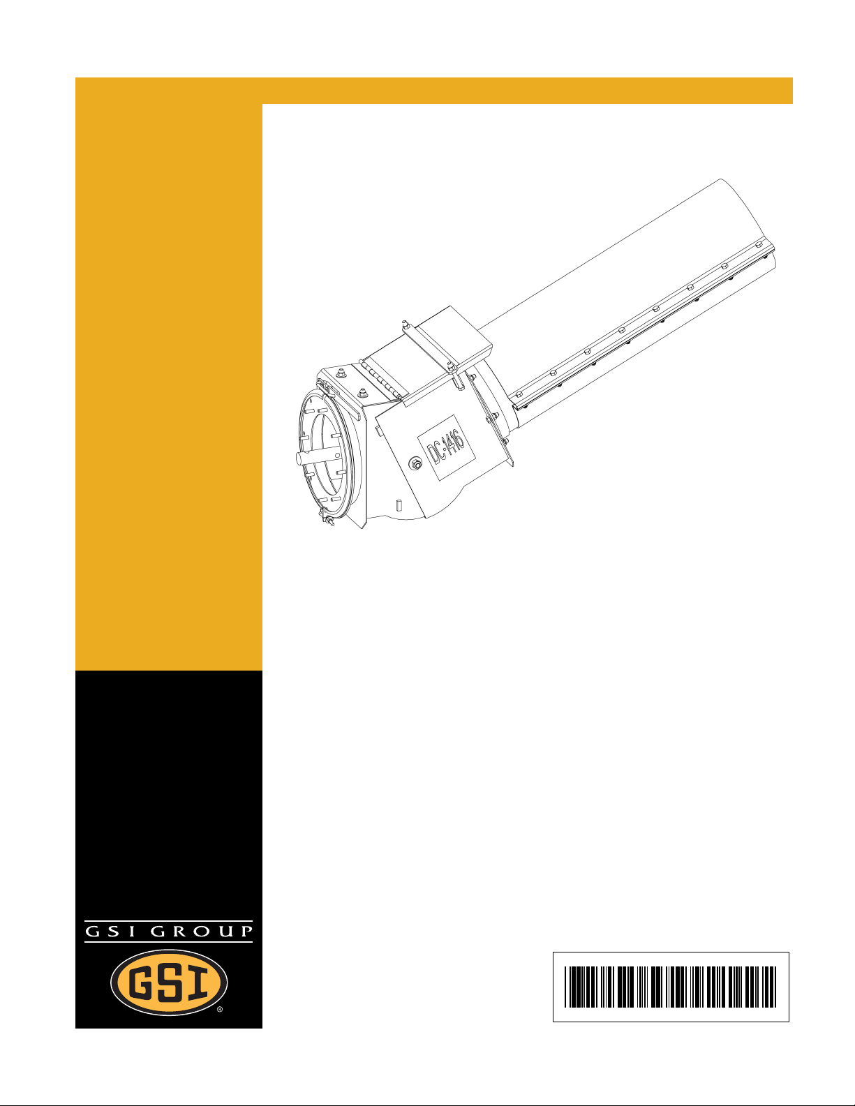
6", 8" and 10" Variable Angle
Auger Connector
Assembly and Installation Manual
PNEG-1060
Date: 03-11-08
PNEG-1060
Page 2
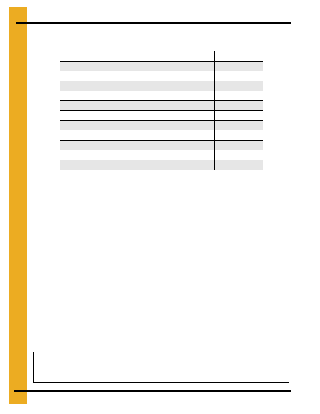
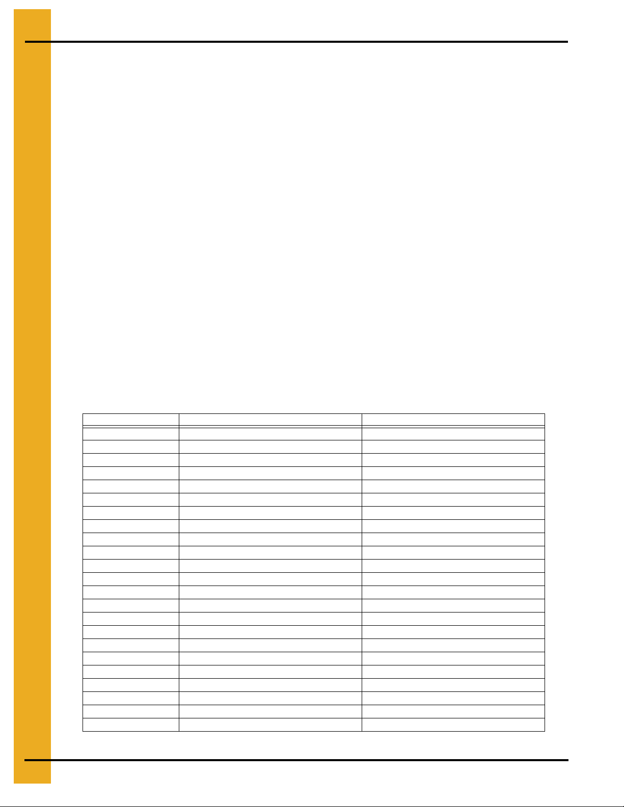
Part #
GK2250 6" 6" 13/16" Round 13/16" Round
GK2270 6" 6" 1" Square 1" Round
GK22501 6" 6" 1" Round 1" Round
GK2260 6" 8" 13/16" Round 1-1/4" Round
GK2271 6" 8" 1" Square 1-1/4" Round
GK22601 6" 8" 1" Round 1-1/4" Round
GK2257 8" 8" 1-1/4" Round 1-1/4" Round
GK2268 8" 10" 1-1/4" Round 1-1/2" Round
GK2262 10" 10" 1-1/2" Round 1-1/2" Round
GK2272 10" 10" 1-1/4" Square 1-1/2" Round
GK6003 10" 10" 1" Square 1-1/2" Round
Tube Assembly Flight Assembly
Intake Size Discharge Size Intake Shaft Discharge Shaft
Personnel operating or working around this equipment should read this manual. This
manual must be delivered with equipment to its owner. Failure to read this manual and its
safety instructions is a misuse of the equipment. Any misuse of the equipment may void
the warranty.
2 PNEG-1060 6", 8" and 10" Variable Angle Auger Connector
Page 3

Table of Contents
Contents
Chapter 1 Introduction ........................................................................................................................................ 4
Chapter 2 Safety ..................................................................................................................................................5
Safety Guidelines ............................................................................................................................... 5
Operator Qualifications ....................................................................................................................... 8
Chapter 3 Safety Decals .....................................................................................................................................9
Chapter 4 Installation ........................................................................................................................................ 11
Inclined Auger Support ................................. .................................................... ................................ 11
Connecting Box Angle Adjustment ............................ .................................................... ................... 12
Horsepower for an Auger System with an Inclined Discharge ......................................................... 12
Chapter 5 Assembly Instructions ....................................................................................................................13
Chapter 6 Parts List ..........................................................................................................................................14
VAAC Parts ...................................................................................................................................... 14
6"-6" Flight Assembly Parts .............................................................................................................. 16
6"-8" Flight Assembly Parts .............................................................................................................. 17
8"-8" Flight Assembly Parts .............................................................................................................. 18
8"-10" Flight Assembly Parts ..................... ... .... ... ... ... .... ... ... .......................................... ... ... .......... ... 19
10"-10" Flight Assembly Parts .......................................................................................................... 20
VAAC Box Parts ............................................................................................................................... 21
Chapter 7 Warranty ...........................................................................................................................................23
PNEG-1060 6", 8" and 10" Variable Angle Auger Connector 3
Page 4

1. Introduction
General Information
1. GSI reserves the right to improve its product whenever possible and practical to do so. We reserve
the right to change, improve, and modify products at any time without obligation to make changes,
improvements, and modifications on equipment sold previously.
2. Receiving merchandise and filing claims
a. When receiving merchandise, check both the quantity of parts and their descriptions against
the packing list enclosed within each package. All claims for freight damage or shortage must
be made by the consignee within ten (10) days from the date of the occurrence of freight
damage. The consignee should accept the shipment after noting the damage or loss on the Bill
of Lading (BOL).
3. The variable angle auger connectors have been designed and manufactured to provide years of
dependable service. The care and maintenance of this machine will affect the service and
satisfaction obtained. Observing the instructions and suggestions in this manual contributes to the
satisfactory service provided by this equipment. If additional information or assistance should be
required, please contact the factory or your local dealer.
Capacity
1. The capacities may vary greatly under different conditions. The following factors play a role in the
performance of the auger:
• Speed
• Angle of operation
• Moisture content*
* For example, a twenty-five percent (25%) moisture could cut capacity by as much as forty
percent (40%) under some conditions.
• Amounts of foreign matter
• Different materials
• Methods of feeding
4 PNEG-1060 6", 8" and 10" Variable Ang le Auger Connector
Page 5
2. Safety
Safety Guidelines
This manual contains information that is important for you, the owner/operator, to know and understand.
This information relates to protecting personal safety and preventing equipment problems. It is the
responsibility of the owner/operator to inform anyone operating or working in the area of this equipment
of these safety guidelines. To help you recognize this information, we use the symbols that are defined
below. Please read the manual and pay attention to these sections. Failure to read this manual and its
safety instructions is a misuse of the equipment and may lead to serious injury or death.
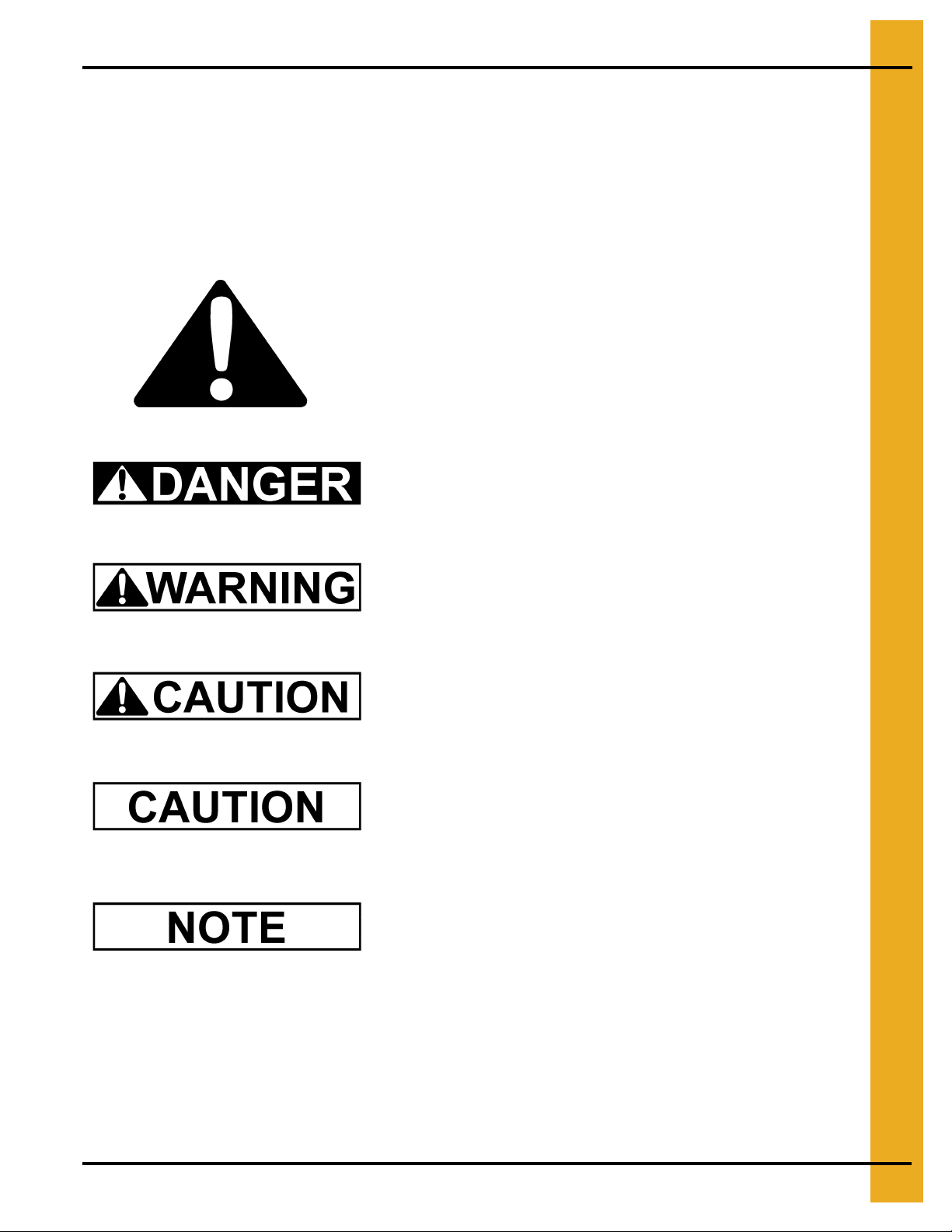
This is the safety alert symbol. It is used to alert you
to potential personal injury hazards. Obey all safety
messages that follow this symbol to avoid possible
injury or death.
DANGER indicates an imminently hazardous situation
which, if not avoided, will result in death or serious injury.
WARNING indicates a potentially hazardous situation
which, if not avoided, could result in death or serious injury.
CAUTION indicates a potentially hazardous situation which,
if not avoided, may result in minor or moderate injury.
CAUTION used without the safety alert symbol indicates a
potentially hazardous situation which, if not avoided, may
result in property damage.
NOTE indicates information about the equipment that you
should pay special attention.
PNEG-1060 6", 8" and 10" Variable Angle Auger Connector 5
Page 6

2. Safety
General Safety Guidelines
A. DO NOT make any alterations to the equipment. Any alteration may produce a very dangerous
situation that could result in SERIOUS INJURY or even DEATH.
B. This equipment shall be installed in accordance with any regulations or installation codes that are
required by law. Authorities having jurisdiction should be consulted before installations are made.
C. Untrained operators subject themselves and others to SERIOUS INJURY or DEATH. NEVER
allow untrained personnel to operate this equipment.
D. Keep children and other unqualified personnel out of the working area at ALL times.
E. NEVER start equipment until ALL persons are clear of the work area.
F. Be sure ALL operators are adequately rested and prepared to perform ALL functions of operating
the equipment.
G. DO NOT wear loose fitting clothing when working around augers. Keep hair, loose clothing, and
shoestrings away from rotating and moving parts.
H. NEVER allow any person intoxicated or under the influence of alcohol or drugs to operate
the equipment.
I. NEVER allow anyone inside a bin, truck, or wagon which is being unloaded by an auger or
conveyor. Flowing grain can trap and suffocate in seconds.
J. Make sure someone is nearby who is aware of the proper shut down sequence in the event of an
accident or emergency.
K. NEVER work alone.
L. ALWAYS think before acting. DO NOT act impulsively around the equipment.
M. Make sure ALL equipment is locked in position before operating.
N. ALWAYS keep hands and feet away from the auger intake and other moving parts.
O. NEVER attempt to assist machinery operation or to remove trash from equipment while
in operation.
P. NEVER drive, stand, or walk under the equipment.
Q. Use caution not to hit the auger when positioning the load.
R. Use ample overhead lighting after sunset to light the work area.
S. ALWAYS lock out ALL power to the equipment when finished unloading.
T. Keep area around intake free of obstacles such as electrical cords, blocks, etc. that might
trip workers.
6 PNEG-1060 6", 8" and 10" Variable Angle Auger Connector
Page 7
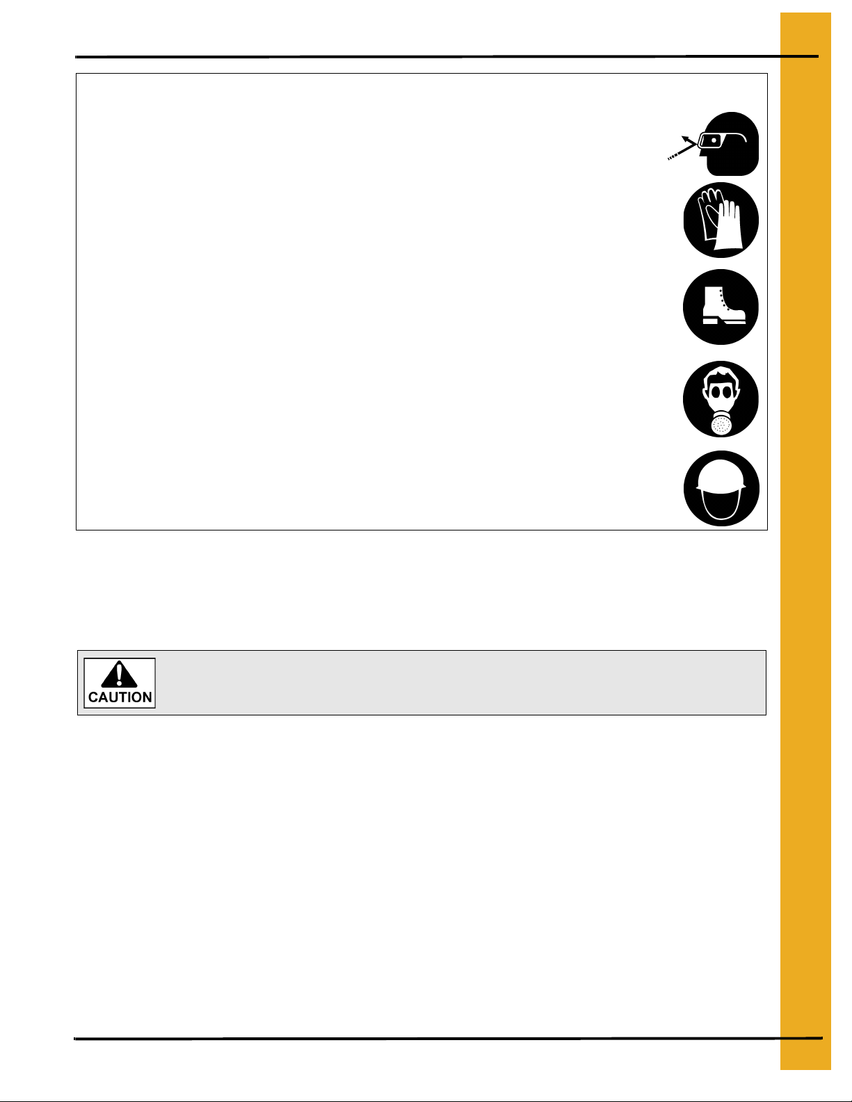
Wear Protective Clothing
Wear close fitting clothing and safety equipment appropriate
to the job.
Remove all jewelry.
2. Safety
Eye Protection
Long hair should be tied up and back.
Safety glasses should be worn at all times to protect eyes
from debris.
Wear gloves to protect your hands from sharp edges on
plastic or steel parts.
Wear steel toe boots to help protect your feet from falling
debris. Tuck in any loose or dangling shoe strings.
A respirator may be needed to prevent breathing potentially
toxic fumes and dust.
Wear hard hat to help protect your head.
Emergency Shut Down Sequence
A. In an emergency, shut down the power source.
Pinch Points
Gloves
Steel Toe Boots
Respirator
Hard Hat
A Pinch Point is a narrow area between two surfaces that is likely to trap or catch
objects and so is a potential safety hazard.
A. Components of this equipment have sharp edges which can scrape and/or cut an operator.
B. A moving auger can sever an operator’s limbs or even kill him/her.
Shields and Guards
A. ALWAYS keep ALL shields and guards in place during operation.
GSI will replace decals free of charge.
PNEG-1060 6", 8" and 10" Variable Angle Auger Connector 7
Page 8
2. Safety
Operator Qualifications
A. The User/Operator must be competent and experienced to operate auger equipment. Anyone who
works with or around augers must have good common sense in order to be qualified. These
persons must also know and meet all other qualifications, such as:
i. Any person who has not read and/or does not understand all operation and safety pro cedures
is not qualified to operate any auger systems.
ii. Certain regulations apply to personnel operating power machinery. Personnel under the age
of 18 years may not operate power machinery, including augers. It is your responsibility, as
owner and/or supervisor, to know what these regulations are in your area or situation.
iii. Unqualified or incompetent persons are to remain out of the work area.
iv. O.S.H.A. (Occupational Safety and Health Administration) regulations state: “At the time of
initial assignment and at least annually thereafter, the employer shall instruct every employee
in the safe operation and servicing of all equipment with which the employee is, or will be
involved”. (Federal Occupational Safety and Health Standards for Agriculture. Sub Part D,
Section 19287.57 (a) (6)).
B. As a requirement of O.S.H.A., it is necessary for the employer to train the employee in the safe
operating and safety procedures for this auger. The sign-off sheet is for your convenience and
personal record keeping. All unqualified persons should always stay ou t of work area. It is strongly
recommended that another qualified person who knows the shut down p rocedure is in the area in
the event of an emergency.
Date Employee Name Supervisor Name
8 PNEG-1060 6", 8" and 10" Variable Angle Auger Connector
Page 9

3. Safety Decals
The illustration shows what the decals look like and where they should be located on the equipment.
Inspect all decals and replace any that are illegible, worn, or missing. Contact your local dealer or the
manufacturer to order replacement decals free of charge.
VAAC Decal List
Ref # Part # Description Size
1 DC-1416 Danger - Rotating Auger 4" x 5-1/4"
ROTATING AUGER!
• DISCONNECT AND LOCKOUT POWER BEFORE
SERVICING, ADJUSTING OR CLEANING.
• KEEP HANDS, FEET, HAIR AND LOOSE
CLOTHING AWAY FROM ROTATING AUGER AND
MOVING PARTS AT ALL TIMES.
• NEVER REMOVE OR MODIFY GUARDS OR
SHIELDS.
FAILURE TO HEED WILL RESULT IN
SERIOUS INJURY OR DEATH!
DC-1416
1
DC-1416
PNEG-1060 6", 8" and 10" Variable Angle Auger Connector 9
Page 10

3. Safety Decals
A. DANGER Sign No. DC-1395 was supplied with your bin unloading equipment. This safety sign
should be applied to the side of the bin near the bin opening, so it will be viewed by people
entering into the bin storage building. Do not cover any safety signs or any other signs that are
already there.
B. If the safety sign location suggested is not in full view because of equipment modifications, other
equipment in the area or any other reason, then locate the safety sign in a more suitable location.
C. Be certain the surface is clean, dry and free of dirt and oil. Peel paper backing from decals and
stick into place. The adhesive backing will bond on contact.
NOTE: Remember, safety signs provide important safety information for people working near bin
unloading equipment that is in operation.
NOTE: If the safety sign cannot be easily read for any reason or has been painted over, replace it
immediately. Additional safety signs may be obtained free of charge from your dealer, distributor
or ordered from the factory.
Order SAFETY SIGN NO. DC-1395.
10 PNEG-1060 6", 8" and 10" Variable Angle Auger Connector
Page 11

4. Installation
With an operating range of 0° to 25°, the variable angle auger connector can be used for a variety of
applications. The intake end should attach to standard flange rings for standard bin unloading flight and
tubes. The discharge side of the connector box can bolt to standard flange rings, or it can make a smooth
tube type connection using the short flanged tube with connecting band. The smooth tube connection
allows standard utility augers to be attached to the connector box.
The Figure 4A below shows the intake side with a VAAC connector box attached to an unloading tube
and flight. The discharge side of the VAAC connector box is attached to a standard utility auger.
Figure 4A
Inclined Auger Support
Figure 4A shows two different methods of supporting the inclined auger.
NOTE: The connector box CANNOT support the weight of the auger system attached to the out put side
of the connector box.
Loosen lid strap on connector box before raising or lowering incline auger or
damage may occur to equipment. The connector box will not raise higher than 25°.
OPTION A: WINCH KIT - a winch kit provides an easy means to adjust the discharge height of the
inclined auger. The kit includes winch, winch mount, roller assembly, roller assembly
mounts, lift cable and hardware.
OPTION B: SUPPORT STAND - An A-frame support stand provides a band on support for incline
auger. The support stand can be atta ched at different locations along th e auger tube to
create various operating angles.
PNEG-1060 6", 8" and 10" Variable Angle Auger Connector 11
Page 12

4. Installation
Connecting Box Angle Adjustment
DO NOT adjust the angle while the auger is in operation. Stop the machine and
lock out power before cleaning, adjusting, or servicing.
DO NOT operate with cover open.
The inclined auger must always be supported. The connector box cannot support
the weight of the auger system attached to the output side of the connector box.
1. Loosen the cover strap on the connector box before changing the angle of operation.
2. Change angle of the inclined auger, by re-supporting the inclined auger at the desired angle.
3. Check to see if the U-joint is centered with pivot bolts and make sure the input flight is not rubbing
on the bearing or bearing hanger on the inside of the connector box.
4. Close cover and secure the cover strap.
Horsepower for an Auger System with an Inclined Discharge
To determine the horsepower required for the auger system, follow the Steps 1-3 and use the
Chart Below.
1. Determine the overall length of auger system (horizontal plus inclined unit).
2. Multiply the total auger system length by the horsepower per foot from the Chart Below.
3. Round horsepower up to the next common size motor.
Horsepower Chart
Auger Diameter Per Foot Horsepower Multiplier
6" 0.1
8" 0.15
10" 0.23
These horsepower recommendations are for augering reasonably dry grain at varying angles. High
moisture grain (above 15%) will require greater power and maximum possible capacity will be less with
high moisture grain than with dry grain.
Example for 10" unit:
1. 16' Horizontal portion and 11' inclined portion = 27' total length of auger system.
2. 27 x .23 = 6.21 HP.
3. Round up to 7 HP motor.
Refer to the installation manual received with the unloading equipment for
information on safety and operating procedures. This should include start-up,
shut down, lock out, break-in, full load operation, power source and troubleshooting.
12 PNEG-1060 6", 8" and 10" Variable Angle Auger Connector
Page 13

5. Assembly Instructions
1. Connect the inlet stub to the bin unloading flight.
2. Connect the box weldment inlet flange to the unloading tube flange using the quick clamp or by
directly bolting them together. (NOTE: If you have a 6" to 8" or 8" to 10" VAAC, bolt the adapter
plate to the box weldment inlet flange before attaching to the bin unloading tube flange.)
3. Remove cover strap.
4. Attach the incline auger flight to the discharge connecting stub.
5. Fasten the outlet tube to the inclined auger tube using the connecting band.
6. Once the angle of the auger is adjusted, support auger with one of the options shown on Page 11.
7. Replace cover strap over the lid and tighten.
Figure 5A
PNEG-1060 6", 8" and 10" Variable Angle Auger Connector 13
Page 14

6. Parts List
VAAC Parts
Ref # Part # Description
GK5187
5" VAAC Flight Assembly 6" 6"
GK6846 1" Round 1" Round
GK5190
1
GK7256 6" 1" Round
GK5189 8" 1-1/4" Round See Page 18
GK5193
GK5192 10" 1-1/2" Round
GK6002 10" 1" Square
7" VAAC Flight Assembly
9" VAAC Flight Assembly
VAAC Parts
Intake
Size
Discharge
6"
8"
Size
8"
10"
Intake Shaft
13/16" Round 13/16" Round
13/16" Round
1-1/4" Round
Discharge
Shaft
1-1/4" Round
1-1/2" Round
Page #
See Page 16GK5188 1" Square 1" Round
See Page 17GK5191 6" 1" Square
See Page 19
See Page 20GK5194 10" 1-1/4" Square
14 PNEG-1060 6", 8" and 10" Variable Angle Auger Connector
Page 15

Ref # Part # Description System
6. Parts List
GK2241
2
GK2251 8"
GK2258 10"
GK2246
3
GK2256 8"
GK2266 10"
GK1048
4
GK1015 8"
GK1883 10"
5 S-2086 3/8"-16 x 1-1/2" HHCS Zinc Grade 8 ALL
6 S-7383 3/8"-16 Nylock Nut Zinc Grade 5 ALL
S-7382 5/16"-18 Nylock Nut Zinc Grade 5 6" and 8"
7
S-7383 3/8"-16 Nylock Nut Zinc Grade 5 10"
8 S-1937 5/16" Flat Washer YDP 6" and 8"
S-4275 5/16"-18 x 3/4" HHTB Zinc Grade 5 6" and 8"
9
S-7469 3/8"-16 x 1" HHCS Zinc Grade 5 10"
GK2245
VAAC Box Assembly
Outlet Tube
Connecting Band
6"
6"
6"
6"
10
GK2255 8"
GK4956 10"
11 S-248 3/8" Flat Washer YDP ALL
GK1357 1" Hanger Bearing 6"
12
GK1359 1-1/4" Hanger Bearing 8"
GK4253 1-1/2" Hanger Bearing 10"
13 S-2071 3/8"-16 x 1-1/4" HHCS Zinc Grade 5 ALL
GK1280 6"-8" Mounting Adapter Ring 6"-8"
14
GK1298 8"-10" Mounting Adapter Ring 8"-10"
GK1013 6" Quick Clamp Band Assembly 6"
15
GK1279 8" Quick Clamp Band Assembly 8"
GK1299 10" Quick Clamp Band Assembly 10"
Cover Strap
PNEG-1060 6", 8" and 10" Variable Angle Auger Connector 15
Page 16

6. Parts List
6"-6" Flight Assembly Parts
6"-6" Flight Assembly Parts
Ref # Part # Description
1 GK2269 Intake Shaft 1" O.D. x 1" SQ x 7-5/8" Long
2 S-8324 5/16"-18 Stover Nut Zinc Grade C
3 GK1266 U-Joint 1" Bore x 5" Long
4 S-7076 5/16"-18 x 2-1/2" HHCS Zinc Grade 5
5 GK2248 Intermediate Shaft 1" O.D. x 4" Long
6 S-8251 3/8"-16 Stover Nut Zinc Grade C
7 GK2243 VAAC 6" Fli ght x 9" Long
8 S-3727 3/8"-16 x 1-3/4" HHCS Zinc Grade 8
9 GK2247 Discharge Shaft 1" O.D. x 5" Long
10 GK2244 Discharge Shaft 1":13/16" O.D. x 5-1/16" Long
11 GK5706 Intake Shaft 1" O.D. x 7-7/8" Long
12 GK2249 Intake Shaft 1":13/16" O.D. x 5-3/8" Long
16 PNEG-1060 6", 8" and 10" Variable Angle Auger Connector
Page 17

6"-8" Flight Assembly Parts
6. Parts List
6"-8" Flight Assembly Parts
Ref # Part # Description
1 GK4690 Intake Shaft 1":1-1/4" O.D.:1" SQ x 7-5/8" Long
2 S-8324 5/16"-18 Stover Nut Zinc Grade C
3 GK1266 U-Joint 1" Bore x 5" Long
4 S-7076 5/16"-18 x 2-1/2" HHCS Zinc Grade 5
5 GK2253 VAAC 8" Flight x 7-1/4" Long
6 S-8317 7/16"-14 Stover Nut Zinc Grade C
7 S-7013 7/16"-14 x 2-1/2" HHCS Zinc Grade 5
8 GK2254 Discharge Shaft 1":1-1/4" O.D. x 11" Long
9 GK5704 Intake Shaft 1":1-1/4":1" O.D. x 7-9/16" Long
10 GK1264 Intake Shaft 13/16":1-1/4":13/16" O.D. x 5-3/8" Long
PNEG-1060 6", 8" and 10" Variable Angle Auger Connector 17
Page 18

6. Parts List
8"-8" Flight Assembly Parts
8"-8" Flight Assembly Parts
Ref # Part # Description
1 GK1283 Intake Shaft 1-1/4":1" O.D. x 7-7/8" Long
2 S-8324 5/16"-18 Stover Nut Zinc Grade C
3 GK1266 U-Joint 1" Bore x 5" Long
4 S-7076 5/16"-18 x 2-1/2" HHCS Zinc Grade 5
5 GK2253 VAAC 8" Flight x 7-1/4" Long
6 S-8317 7/16"-14 Stover Nut Zinc Grade C
7 S-7013 7/16"-14 x 2-1/2" HHCS Zinc Grade 5
8 GK2254 Discharge Shaft 1-1/4":1" O.D. x 11" Long
18 PNEG-1060 6", 8" and 10" Variable Angle Auger Connector
Page 19

8"-10" Flight Assembly Parts
6. Parts List
8"-10" Flight Assembly Parts
Ref # Part # Description
1 GK1292 Intake Shaft 1-1/4":1-1/2":1-1/4" O.D. x 8-1/8" Long
2 S-8251 3/8"-16 Stover Nut Zinc Grade C
3 GK1291 U-Joint 1-1/4" Bore x 7" Long
4 S-6762 3/8"-16 x 2-1/2" HHCS Zinc Grade 5
5 GK2261 VAAC 10" Flight x 9" Long
6 S-8315 1/2"-13 Stover Nut Zinc Grade C
7 S-8314 1/2"-13 x 3-1/2" HHCS YDP Grade 8
8 GK2264 Discharge Shaft 1-1/4":1-1/2" O.D. x 11-1/2" Long
PNEG-1060 6", 8" and 10" Variable Angle Auger Connector 19
Page 20

6. Parts List
10"-10" Flight Assembly Parts
10"-10" Flight Assembly Parts
Ref # Part # Description
1 GK1996 Intake Shaft 1-1/4":1-1/2" O.D.:1" SQ x 8-3/8" Long
2 S-8251 3/8"-16 Stover Nut Zinc Grade C
3 GK1291 U-Joint 1-1/4" Bore x 7" Long
4 S-6762 3/8"-16 x 2-1/2" HHCS Zinc Grade 5
5 GK2261 VAAC 10" Flight x 9" Long
6 S-8315 1/2"-13 Stover Nut Zinc Grade C
7 S-8314 1/2"-13 x 3-1/2" HHCS YDP Grade 8
8 GK2264 Discharge Shaft 1-1/4":1-1/2" O.D. x 11-1/2" Long
9 GK2273 Intake Shaft 1-1/4":1-1/2" O.D.:1-1/4" SQ x 7-1/4" Long
10 GK2263 Intake Shaft 1-1/4":1-1/2" O.D. x 8-1/8"
20 PNEG-1060 6", 8" and 10" Variable Angle Auger Connector
Page 21

VAAC Box Parts
6. Parts List
VAAC Box Parts
Ref # Part # Description System
GC05585
1
GC03725 8"
GC05606 10"
GC05575
2
GC03730 8"
GC05600 10"
3 S-7935 1/2"-13 x 1" HHCS Zinc Grade 5 ALL
4 S-2121 1/2" Flat Washer Plated ALL
5 S-8260 1/2"-13 Nylock Nut Zinc Grade 5 ALL
Intake VAAC Box Assembly
Discharge VAAC Box Assembly
6"
6"
PNEG-1060 6", 8" and 10" Variable Angle Auger Connector 21
Page 22

NOTES
22 PNEG-1060 6", 8" and 10" V ariable Angle Auger Connector
Page 23

7. Warranty
The GSI Group Warranty
THE GSI GROUP (GSI) WARRANTS ALL PRODUCTS WHICH IT MANUFACTURES TO BE FREE OF
DEFECTS IN MATERIAL AND WORKMANSHIP UNDER NORMAL USAGE AND CONDITIONS FOR
A PERIOD OF 12 MONTHS AFTER RETAIL SALE TO THE ORIGINAL END USER. THE
PURCHASER’S SOLE REMEDY AND GSI’S ONLY OBLIGATION SHALL BE TO REPAIR OR
REPLACE, AT GSI’S OPTION AND EXPENSE, PRODUCTS THAT, IN GSI’S SOLE JUDGMENT,
CONTAIN A MATERIAL DEFECT DUE TO MATERIALS OR WORKMANSHIP. ALL DELIVERY AND
SHIPMENT CHARGES TO AND FROM GSI’S FACTORY WILL BE PURCHASER’S RESPONSIBILITY.
EXPENSES INCURRED BY OR ON BEHALF OF THE PURCHASER WITHOUT PRIOR WRITTEN
AUTHORIZATION FROM AN AUTHORIZED EMPLOYEE OF GSI SHALL BE THE SOLE
RESPONSIBILITY OF THE PURCHASER.
EXCEPT FOR THE LIMITED WARRANTY EXPRESSED ABOVE, GSI MAKES NO FURTHER
WARRANTY OF ANY KIND, EXPRESS OR IMPLIED, INCLUDING, WITHOUT LIMITATION,
WARRANTIES OF MERCHANTABILITY OR FITNESS FOR A PARTICULAR PURPOSE
OR USE IN CONNECTION WITH (I) PRODUCT MANUFACTURED OR SOLD BY GSI OR (II) ANY
ADVICE, INSTRUCTION, RECOMMENDATION OR SUGGESTION PROVIDED BY AN AGENT,
REPRESENTATIVE OR EMPLOYEE OF GSI REGARDING OR RELATED TO THE CONFIGURATION,
INSTALLATION, LAYOUT, SUITABILITY FOR A PARTICULAR PURPOSE, OR DESIGN OF
SUCH PRODUCTS.
GSI SHALL NOT BE LIABLE FOR ANY DIRECT, INDIRECT, INCIDENTAL OR CONSEQUENTIAL
DAMAGES, INCLUDING, WITHOUT LIMITATION, LOSS OF ANTICIPATED PROFITS OR BENEFITS.
PURCHASER’S SOLE AND EXCLUSIVE REMEDY IS AS SET FORTH IN THE LIMITED WARRANTY
EXPRESSED ABOVE, WHICH SHALL NOT EXCEED THE AMOUNT PAID FOR THE PRODUCT
PURCHASED. THIS WARRANTY IS NOT TRANSFERABLE AND APPLIES ONLY TO THE ORIGINAL
PURCHASER. GSI SHALL HAVE NO OBLIGATION OR RESPONSIBILITY FOR ANY
REPRESENTATIONS OR WARRANTIES MADE BY OR ON BEHALF OF ANY DEALER, AGENT OR
DISTRIBUTOR OF GSI.
GSI ASSUMES NO RESPONSIBILITY FOR CLAIMS RESULTING FROM ERECTION DEFECTS OR
UNAUTHORIZED MODIFICATIONS TO PRODUCTS WHICH IT MANUFACTURED. MODIFICATIONS
TO PRODUCTS NOT SPECIFICALLY DELINEATED IN THE MANUAL ACCOMPANYING THE
EQUIPMENT AT INITIAL SALE WILL NULLIFY THE PRODUCT WARRANTY THAT MIGHT HAVE
BEEN OTHERWISE AVAILABLE.
THE FOREGOING WARRANTY SHALL NOT EXTEND TO PRODUCTS OR PARTS WHICH HAVE
BEEN DAMAGED BY NEGLIGENT USE, MISUSE, ALTERATION OR ACCIDENT. THIS WARRANTY
EXTENDS SOLELY TO ONLY PRODUCTS MANUFACTURED BY GSI. THIS WARRANTY IS
EXCLUSIVE AND IN LIEU OF ALL OTHER WARRANTIES EXPRESS OR IMPLIED. GSI RESERVES
THE RIGHT TO MAKE DESIGN OR SPECIFICATION CHANGES AT ANY TIME.
PRIOR TO INSTALLATION, PURCHASER HAS THE RESPONSIBILITY TO COMPLY WITH ALL
FEDERAL, STATE AND LOCAL CODES WHICH MAY APPLY TO THE LOCATION AND
INSTALLATION OF PRODUCTS MANUFACTURED OR SOLD BY GSI.
PHLEGAL: #1832020 v1 (139LG01!.DOC) (revised Decembe r 2005)
PNEG-1060 6", 8" and 10" Variable Angle Auger Connector 23
Page 24

This equipment shall be installed in accordance with
the current installation codes and applicable
regulations which should be carefully followed in all
cases. Authorities having jurisdiction should be
consulted before installations are made.
Copyright © 2008 by GSI Group
Printed in the USA
GSI Group
1004 E. Illinois St.
Assumption, IL 62510-0020
Phone: 1-217-226-4421
Fax: 1-217-226-4420
www.gsiag.com
 Loading...