

Page 1
PNEG-1058
04-04-03
Revision: 0
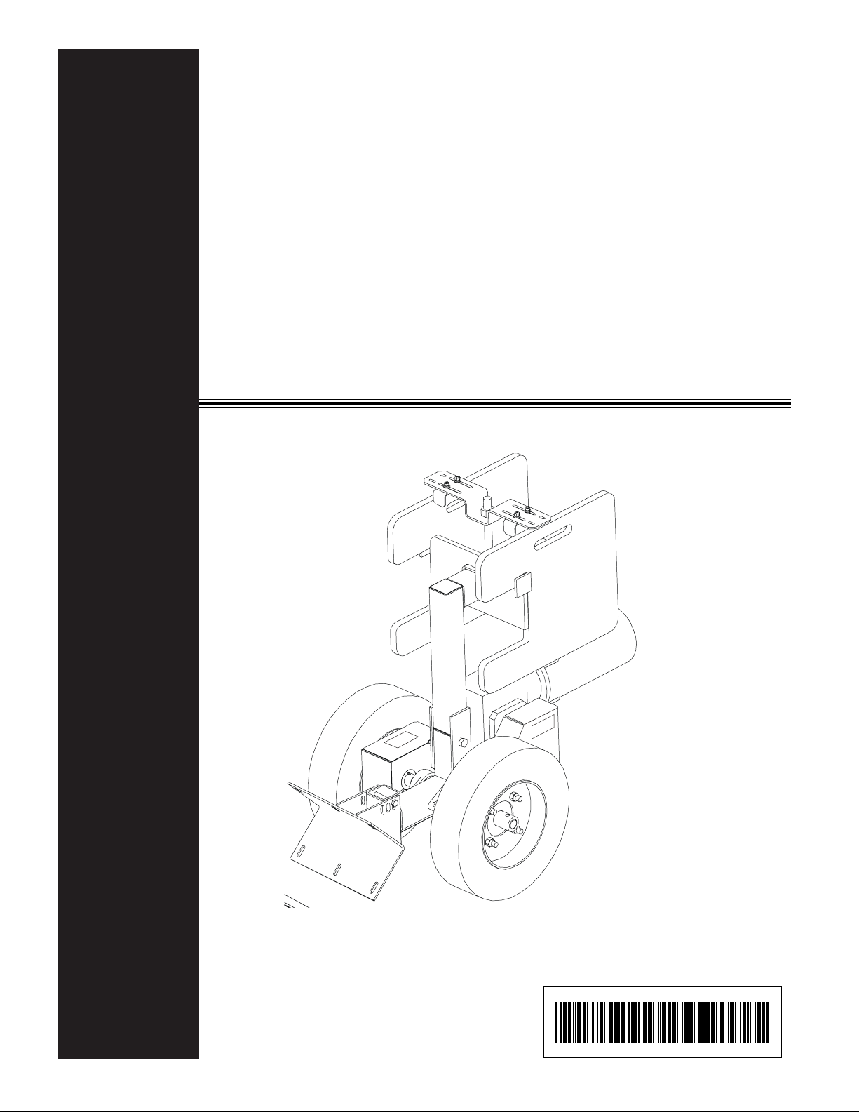
Sweep Tractor
Assembly Instructions
Assembly & Installation Manual
Sweep Tractor
Assembly Instructions
PNEG-1058
04/04/03
Rev. No. 0
PNEG-1058
Page 2

Page 3

TABLE OF CONTENTS
Safety ......................................................................................................... 4
General Information ..................................................................................... 12
Decals ........................................................................................................ 13
Assembly Section
Sweep Tractor Assembly ....................................................................... 14
End Wheel Assembly.............................................................................16
Sweep Tractor to Shield......................................................................... 17
Parts...........................................................................................................18-20
Warranty - (Inside Back Cover)
Personnel operating or working around this equipment should read this
manual. This manual must be delivered with equipment to its owner.
Failure to read this manual and its safety instructions is a misuse of the
equipment. Any misuse of the equipment may void the warranty.
Sweep Tractor Assembly Instructions PNEG -1058
3
Page 4
SAFETY GUIDELINES
This manual contains information that is important for you, the owner/operator , to know and
understand. This information relates to protecting personal safety and preventing
equipment problems. It is the responsibility of the owner/operator to inform anyone
operating or working in the area of this equipment of these safety guidelines. T o help you
recognize this information, we use the symbols that are defined below.
Please read the manual and pay attention to these sections. Failure to read this manual
and it’s safety instructions is a misuse of the equipment and may lead to serious injury or death.
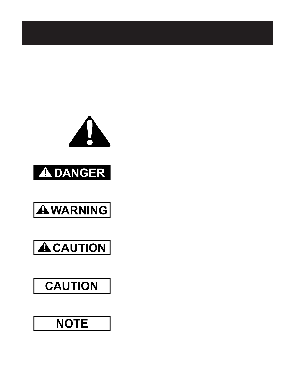
This is the safety alert symbol. It is used to alert you
to potential personal injury hazards. Obey all
safety messages that follow this symbol to avoid possible injury
or death.
DANGER indicates an imminently hazardous situation which, if not
avoided, will result in death or serious injury .
WARNING indicates a potentially hazardous situation which, if not
avoided, could result in death or serious injury .
CAUTION indicates a potentially hazardous situation which, if not
avoided, may result in minor or moderate injury .
CAUTION used without the safety alert symbol indicates a potentially
hazardous situation which, if not avoided, may result in property
damage.
NOTE indicates information about the equipment that you should pay
special attention to.
4
PNEG-1058 Sweep Tractor Assembly Instructions
Page 5
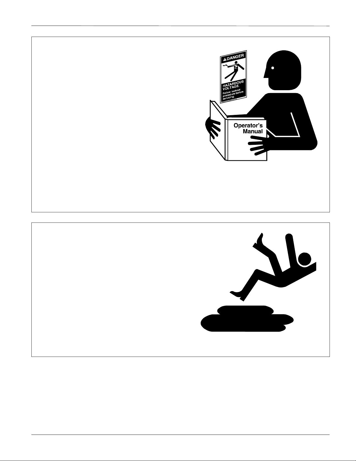
FOLLOW SAFETY INSTRUCTIONS
Carefully read all safety messages in this manual
and safety signs on your equipment. Keep signs
in good condition. Replace missing or damaged
safety signs. Be sure new equipment components and repair parts include the current safety
signs. Replacement safety signs are available
from the manufacturer.
Learn how to operate the machine and how to
use controls properly . Do not let anyone operate
without instruction.
Keep your machinery in proper working condition. Unauthorized modifications to the machine
may impair the function and/or safety and affect
machine life.
Safety
If you do not understand any part of this manual
and need assistance, contact your dealer.
PRACTICE SAFE MAINTENANCE
Understand service procedures before doing
work. Keep area clean and dry.
Never lubricate, service, or adjust machine while
it is in operation. Keep hands, feet, and clothing
from rotating belt and idlers.
Keep all parts in good condition and properly
installed. Fix damage immediately. Replace
worn or broken parts. Remove any build up
grease, oil, or debris.
Sweep Tractor Assembly Instructions PNEG -1058
5
Page 6
Safety
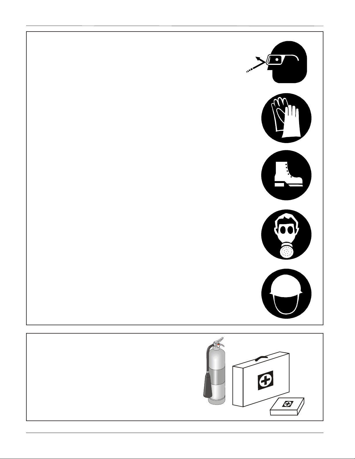
WEAR PROTECTIVE CLOTHING
Wear close fitting clothing and safety equipment
appropriate to the job.
Safety glasses should be worn at all times to
protect eyes from debris.
Wear gloves to protect your hands from sharp
edges on plastic or steel parts.
A respirator may be needed to help prevent
breathing potentially toxic fumes and dust.
Wear hard hat and steel toe boots to help
protect your head and toes from falling debris.
Eye Protection
Gloves
Steel Toe
Boots
PREPARE FOR EMERGENCIES
Be prepared if fire starts.
Keep a first aid kit and fire extinguisher handy .
Keep emergency numbers for doctors, ambu-
lance service, hospital, and fire department
near your telephone.
Respirator
Hard Hat
6
PNEG-1058 Sweep Tractor Assembly Instructions
Page 7

Safety
SAFETY GUIDELINES
1. General Safety Guidelines
A. DO NOT make any alterations to the equipment. Such alterations may produce a very dangerous situation,
where SERIOUS INJURY or DEATH may occur.
B. This equipment shall be installed in accordance with any regulations or installation codes that are required by
law. Authorities having jurisdiction should be consulted before inst allations are made.
C. Untrained operators subject themselves and others to SERIOUS INJURY or DEA TH. NEVER allow untrained
personnel to operate this equipment.
D. Keep children and other unqualified personnel out of the working area at ALL times.
E. NEVER start equipment until ALL persons are clear of the work area.
F. Be sure ALL operators are adequately rested and prepared to perform ALL functions of operating this equipment.
G . Keep hair, loose clothing, and shoestrings away from rotating and moving part s. NEVER wear loose fitting clothing
when working around augers.
H. NEVER allow any person intoxicated or under the influence of alcohol or drugs to operate the equipment.
I. NEVER allow anyone inside a bin, truck, or wagon which is being unloaded by an auger or conveyor. Flowing
grain can trap and suffocate in seconds.
J. Make sure someone is nearby who is aware of the proper shutdown sequence in the event of an accident or
emergency .
K. NEVER work alone.
L. ALWAYS think before acting. NEVER act impulsively around the equipment.
M. Make sure ALL equipment is locked in position before operating.
N. Keep hands and feet away from the auger intake and other moving parts.
O. NEVER attempt to assist machinery operation or to remove trash from equipment while in operation.
P . Use ample overhead lighting after sunset to light the work area.
Q. ALWAYS lockout ALL power to the equipment when finished unloading.
R. Keep area around intake free of obstacles such as electrical cords, blocks, etc. that might trip workers.
Sweep Tractor Assembly Instructions PNEG -1058
7
Page 8

Safety
2. Personal Protective Equipment
A. The proper personal protective equipment should be
worn at ALL times by anyone in the work area.
B. ALWAYS wear safety glasses when in the work area.
C. The operator should NEVER wear jewelry.
2-B
2-C
D. Loose clothing should not be worn. Any clothing that
becomes loosened should be tucked in tightly .
E. Loose or dangling shoe strings should be tucked in.
F. Long hair should be tied up and/or back.
8
2-D, E
2-F
PNEG-1058 Sweep Tractor Assembly Instructions
Page 9

3. In an Emergency Shutdown the Power Source.
4. Hazards
A. Keep clear of all augers. DO NOT ENTER the bin!
B. If you must enter this bin:
1. Shut off and lock out all power .
2. Use safety harness and safety line.
3. Station another person outside the bin.
4. A void the center of the bin.
5. Wear proper breathing equipment or respirator.
C. Failure to heed these warnings will result in serious injury or death.
D. Be cautious of Pinch Points. A Pinch Point a narrow area between two surfaces that
is likely to trap or catch objects and so is a potential safety hazard.
5. Shields and Guards
A. ALW AYS keep ALL shields and guards in place during operation.
Safety
We will replace any missing shields or guards free of charge!
See (page vi) for more information on our Safety First program.
6. Operator Qualifications
A. The User/Operator must be competent and experienced to operate auger equipment. Anyone who works
with or around augers must have good common sense in order to be qualified. These persons must also
know and meet all other qualifications, such as:
1. Any person who has not read and/or does not understand all operation and safety procedures is not
qualified to operate any auger systems.
2. Certain regulations apply to personnel operating power machinery. Personnel under the age of 18
years may not operate power machinery , including augers. It is your responsibility , as owner and/or
supervisor, to know what these regulations are in your area or situation.
3. Unqualified or incompetent persons are to remain out of the work area.
4. O.S.H.A. (Occupational Safety & Health Administration) regulations state: "At the time of initial assignment and at least annually thereafter , the employer shall instruct every employee in the safe operation
and servicing of all equipment with which the employee is, or will be involved." (Federal Occupational
Safety & Health Standards for Agriculture. Subpart D, Section 19287.57 (a) (6).
Sweep Tractor Assembly Instructions PNEG -1058
9
Page 10

Safety
6. Operator Qualifications (cont.)
B. As a requirement of OSHA, it is necessary for the employer to train the employee in the safe operating and
safety procedures for this auger . We included this sign-off sheet for your convenience and personal record
keeping. All unqualified persons are to st ay out of the work area at all times. It is strongly recommended
that another qualified person who knows the shutdown procedure is in the area in the event of an emergency .
A person who has not read this manual and understands all operating and safety instructions is not qualified
to operate the machine.
DATE EMPLOYER'S SIGNATURE EMPLOYEE'S SIGNATURE
1
2
3
4
5
6
7
8
9
10
11
12
13
14
15
16
17
18
19
20
21
22
10
23
24
25
PNEG-1058 Sweep Tractor Assembly Instructions
Page 11

Safety
Our equipment is built to provide
many years of dependable service to
our customers through durable
craftsmanship.
One of the most important aspects of our engineering is SAFETY 1
st
design throughout all
product lines. At our comp any - safety is NO
ACCIDENT!
That is why we have implemented a SAFETY 1
program. Should you ever need guards,
shields, safety decals or owner/operator manuals, simply contact us or your local dealer , and
we will supply you with them FREE OF
CHARGE!
While it is our main goal for our
company to be a world leader in manufacturing,
it is always our first priority to keep our customers safe.
We replace missing guards and shields
FREE OF CHARGE!
st
If you need any of the above listed safety items or have any safety questions, please contact
the manufacturer or your local dealer .
Sweep Tractor Assembly Instructions PNEG -1058
11
Page 12

1. General Information
A. We reserve the right to improve our product whenever possible and practical to do so. We reserve the right to
change, improve, and modify products at any time without obligation to make changes, improvements, and
modifications on equipment sold previously .
B. The Sweep Tractor has been designed and manufactured to give years of dependable service. The care and
maintenance of this machine will affect the satisfaction and service obtained. By observing the instructions
and suggestions we have recommended, the owner should receive competent service for many years. If
additional information or assistance should be required, please contact the factory or your local dealer .
C. Receiving Merchandise and Filing Claims
1. When receiving merchandise, it is important to check both the quantity of parts and their descriptions
with the packing list enclosed within each package. All claims for freight damage or short age must be
made by the consignee within ten (10) days from the date of the occurrence of freight damage. The
consignee should accept the shipment after noting the damage or loss.
For Claims Contact:
The GSI Group Inc.
1004 East Illinois Street
Assumption, IL 62510
Tele: (217) 226-4421
Fax: (217) 226-4420
12
PNEG-1058 Sweep Tractor Assembly Instructions
Page 13

Decals
SAFETY DECALS
Check components shown below to insure that the safety decals are in place and in good condition. If a decal cannot
be easily read for any reason or has been painted over , replace it immediately . Contact your dealer or the manufacturer
to order a replacement decal free of charge.
Chain Guards
SHEAR POINT
Moving parts can
crush and cut. Keep
Chain Guards
DC-1386 Decals located on outside of chain guards.
Sweep Tractor Assembly Instructions PNEG -1058
hands clear of
sprocket and chain.
DC-1386
13
Page 14

Assembly
SWEEP TRACTOR ASSEMBLY INSTRUCTIONS
A . Sweep T ractor Assembly (See Fig. 2 on page 2)
1. Remove wheel hubs from axle. (Assembled for shipping only .)
2. Bolt the adapter plate (2) to the gear motor (3) using
four 3/8" x 1" hex head capscrews with four 3/8"
lockwashers.
3. Install right side chain around the right side sprockets.
4. Slide right side chain guard (12) onto the axle.
5. Bolt the adpater plate (2) to the gear motor mount by
placing a 3/8" x 1-1/2" through the left side slots in the
adapter plate (2), four flat washers, gear motor mount
(4), one flat washer , the right side chain guard (12), and
finally , a hex nut. Repeat this with the lef t side slots in
the adapter plate (13), but replace the right side chain
guard with the left side chain guard mount bracket (14).
(See Fig. 1)
6. Attach the other right side chain guard flange &
support tube weldment (7) to the sweep tractor assembly using (2) 1/2" x 4" hex head capscrews and nuts.
7. Assemble 13 tooth sprocket (5) to gear motor shaft (6)
using a 1/4" key x 1" long. Align 13 tooth sprocket (5)
with 40 tooth sprocket (6) before tightening the
sprocket setscrews.
8. Install chain around the sprockets. Use slots in gear
motor mount to tighten the chain. Once chain is tight,
completely tighten bolts that hold gear motor to mount
from step 5.
9. Bolt the left side chain guard (13) to the mount bracket
(14) using (2) 3/8" x 1" HHCS & lock washers.
15. Attach the weight bracket (11) to the weight bracket
weldment (8) with a 3/4" hex nut. Tighten the nut so
the weight bracket is securely against the top of the
50 lb. weights (9).
16. Slide the weight clamps (10) out against the sides of
the 50 lb. weights (9) and tighten to secure the
weights in place.(See Fig. 1.)
17. Electric wiring for motor and controls shall be installed
by a qualified electrician and must meet the standards
set by the National Electrical Code and all local and a
state codes.
18. Run wiring for motor forward to the sweep shield along
sweep mount tube. Att ach the wiring to the mount
sufficiently to keep wiring from contacting sweep
tractor wheels.
19. At the center of the bin the wiring for the tractor may
either be connected with the sweep flight motor wiring
or a separate wire may be run to the outside of the
bin. If the tractor wiring is connected to the wiring for
the sweep flight motor , then the tractor will turn on and
off with the sweep. If a separate wire is run to the
outside of the bin, then the tractor can be operated
independently.
(2)
Adapter
Plate
(4)
Gear
Motor
Mount
NOTE:
Motor not
shown for
clarity.
10. Replace wheel hubs onto the axle.
1 1. Assemble segmented rubber wheel (1) to hubs with
1/2" nylon locknuts (four for each wheel.)
12. Slide the weight bracket weldment (8) onto the support
tube weldment (7) and secure with a
3/16" x 1-1/2" cotter pin.
13. Place the 50 lb. weights (9) on the weight bracket
weldment (8).
14. Loosely attach the weight clamps (10) to the weight
bracket (1 1) using two 1/4" x 3/4" carriage bolts ,
1/4" lockwasher , & 1/4" flat washer . Do not tighten yet
to allow for adjustment later on.
14
(13) Left Side
Chain Guard
PNEG-1058 Sweep Tractor Assembly Instructions
(4) Gear
Motor Mount
FIG . 1
(12) Right Side
Chain Guard
Page 15

Assembly
(1 1) Weight Bracket
(10) Weight Clamps
1/4" x 3/4" Carriage Bolts
(3) Gear Motor
3/8" x 1-1/2" HHCS
3/4" Hex Nut
(8) Weight
Bracket
Weldment
(9) 50 lb. Weights
3/16" x 1-1/2" Cotter Pin
(7) Support Tube
Weldment
1/2" x 4" HHCS
(6) Gear Motor Shaft
(2) Adapter Plate
3/8" x 1" HHCS
& Lockwashers
3/8" Flatwashers
(Use 4 between plates)
(4) Mount for Gear Motor
(12) Right Side
Chain Guard
Wheel Hub
(6) 40 T ooth
Sprocket
FIG . 2
(5) 13 Tooth Sprocket
1/4" Square Key
(14) Chain Guard Mount Bracket
(13) Left Side Chain Guard
3/8" x 1" HHCS Bolts
with Lockwashers
(1) Segmented
Rubber Wheel
Sweep Tractor
Assembly
1/2" Nylon Locknuts
Sweep Tractor Assembly
Sweep Tractor Assembly Instructions PNEG -1058
15
Page 16

Assembly
B. End Wheel Assembly
If installing sweep tractor to an existing sweep, the current end wheel
components must be removed.
1. Connect stub into flighting using a 5/8" x 4" long hex head capscrew and 5/8" nylon locknut.
2. Install bearing stand onto the stub shaft and bolt it to the sweep shield using a 3/8" x 3" hex
head capscrew , a 3/8" x 3" long carriage bolt, flatwasher , and nylon locknut.
3. Install the end wheel and collar onto the end of the stub shaft. Lock the collar in place with a
1/2" x 3-1/2" long hex head capscrew and 1/2" nylon locknut.
Sweep Shield
Sweep Flight
Bearing Stand
Weldment
Stub Shaft
End Wheel
Collar
FIG . 2
End Wheel Assembly
16
PNEG-1058 Sweep Tractor Assembly Instructions
Page 17

Assembly
C. Sweep Tractor to Shield Assembly
1. Position sweep tractor against the sweep shield approximately 3' from the end wheel.
2. Use the bracket on the sweep tractor to mark the location where the holes need to be drilled into
the sweep shield. You may need to adjust the bolts on the sweep tractor bracket to match the
same height and angle on the sweep shield.
3. After marking the hole location, drill four (4) 7/16" holes and then attach the sweep tractor to
shield using (4) 3/8" x 1" hex head capscrews, (4) flatwashers, and four (4) 3/8" nylon locknuts.
4. Install electric wiring for motor and controls.
All electrical wiring shall be installed by a qualified electrician and must meet
the standards set by the National Electric Code and all local and state codes.
5. Run wiring for motor forward to the sweep shield along sweep mount tube. Att ach the wiring to
the mount sufficiently to keep wiring from contacting sweep tractor wheels.
6. Attach the wiring to the sweep shield and run to the center of the bin.
7. At the center of the bin, the wiring may either be connected with the sweep flight motor or a
separate wire may be ran to the outside of the bin. If the wiring is connected to the wiring of the
sweep flight motor, then the tractor will turn on and of f the sweep. If a separate wire is ran to the
outside of the bin, the sweep tractor can operate independently from the sweep.
Adjustment bolts for adjusting the
angle and height of the bracket
(3/8" x 1" HHCS with flat
washer’s Nylon Locknut)
FIG . 4
Shield to Tractor Assembly
Sweep Tractor Assembly Instructions PNEG -1058
Sweep Shield
17
Page 18

Parts
GK4995 - SWEEP TRACTOR PARTS
12" Tractor Drive Parts
Ref # Part # Desc ript i on
1 GK4967 Mounting B racket for Gear Motor
2 GK2344 Segmented Rubber Wheel
3 GK4975 Shield At t achment B racket
4 GK1049 1" Bore Bearing (2-Hole Flange)
5 GK4977 Wheel S haft
6 GK4979 Sprock et # 50 - 40 Tooth wit h 1" B ore
7 GK4974 Wheel Hub
8 GK4978 Sprock et # 50 - 13 Tooth wit h 1-1/8" Bore
N\S GK5490 Chain RC-50 - 50 Pitc h w/ Connec ti ng Link
N\S GK4980 Chain RC-50 - 58 Pitc h w/ Connec ti ng Link
11 GK4950 Adapter P late
12 GK4976 Gear Mot or Mount ing B rac k et
13 GK5412 Weight S upport S t and
14 GK5416 Weight Clam p Bar
15 GK5417 Weight B rac k et W el dm ent
16 GK5418 Weight Clam p Brac ket
17 GK5432 50 lb. Weight Pai nted
18 S-8312 3/16" x 1-1/2" Zinc Cotter Pin
19 GK5481 Gear Mot or (1/2 hp, 3P H, TEFC)-208 - 230/460V
GK4985 Gear Mot or (1/2 hp, 1P H, TEFC)-115/208 - 230V
GK6386 Gear Mot or (1/2 hp, 1P H, X-Proof)-115/208 - 230V
GK6387 Gear Mot or (1/2 hp, 3P H, X-Proof)-208 - 230/460V
GK6388 Gear Mot or (1/2 hp, 3P H, TEFC)-575V
GK4985 Gear Mot or (1/2 HP , s ingle phas e TEFC)
20 GK5509 Guard: Chain Mount Brac k et
21 GK6373 Tractor Drive Shield
22 GK6374 Tractor Chain Guard
23 GK2356 40 Tooth Sproc k et W el dment #50 1-1/4" Bore
24 S-6297 13 Tooth S procket K eyed #50 1" Bore
18
PNEG-1058 Sweep Tractor Assembly Instructions
Page 19

GK4995 - SWEEP TRACTOR PARTS
14
Parts
16
19
15
17
18
13
2
11
24
7
Sweep Tractor Assembly Instructions PNEG -1058
1
22
23
12
21
8
20
6
4
5
3
19
Page 20

Parts
END WHEEL PARTS
2
2
1
3
1
3
4
5
4
5
Sweep Tractor End Wheel Part List
20
1 GK4952 Stub Shaft for End Wheel
2 GK2172 Bearing Stand Weldment
3 GK2163 Bearing Retainer Weldment w/ Bronze Bushing
4 GK4954 End Wheel
5 GK4951 Collar for End Wheel Stub Shaft
PNEG-1058 Sweep Tractor Assembly Instructions
Page 21

WARRANTY
THE COMP ANY WARRANTS ALL PRODUCTS MANUF ACTURED TO BE FREE OF DEFECTS IN
MA TERIAL AND WORKMANSHIP UNDER NORMAL USAGE AND CONDITIONS FOR A PERIOD OF
TWEL VE (12) MONTHS AFTER RET AIL SALE TO THE ORIGINAL END USER OF SUCH PRODUCTS.
OUR ONL Y OBLIGA TION IS, AND PURCHASER'S SOLE REMEDY SHALL BE TO REP AIR OR
REPLACE, AT THE COMPANY'S OPTION AND EXPENSE, PRODUCTS THAT , IN THE
MANUFACTURERS SOLE JUDGEMENT, CONTAIN A MA TERIAL DEFECT DUE TO MATERIALS OR
WORKMANSHIP . ALL DELIVERY AND SHIPMENT CHARGES TO AND FROM THE F ACTORY WILL BE
PURCHASER'S RESPONSIBILITY . EXPENSES INCURRED BY OR ON BEHALF OF THE
PURCHASER WITHOUT PRIOR WRITTEN AUTHORIZATION FROM AN AUTHORIZED EMPLOYEE OF
THE COMP ANY SHALL BE THE SOLE RESPONSIBILITY OF THE PURCHASER.
EXCEPT FOR THE ABOVE EXPRESS LIMITED WARRANTIES, THE COMP ANY MAKES NO
WARRANTY OF ANY KIND, EXPRESSED OR IMPLIED, INCLUDING , WITHOUT LIMIT A TION,
WARRANTIES OF MERCHANT ABILITY OR FITNESS FOR A P ARTICULAR PURPOSE OR USE IN
CONNECTION WITH (i) PRODUCT MANUFACTURED OR SOLD BY THE COMP ANY OR (ii) ANY
ADVICE, INSTRUCTION, RECOMMENDA TION OR SUGGESTION PROVIDED BY AN AGENT ,
REPRESENT ATIVE OR EMPLOYEE OF THE COMP ANY REGARDING OR RELA TED TO THE
CONFIGURA TION, INSTALLA TION, LA YOUT , SUITABILITY FOR A PARTICULAR PURPOSE, OR
DESIGN OF SUCH PRODUCT OR PRODUCTS.
IN NO EVENT SHALL THE COMPANY BE LIABLE FOR ANY DIRECT , INDIRECT, INCIDENT AL, OR
CONSEQUENTIAL DAMAGES, INCLUDING , WITHOUT LIMIT A TION, LOSS OF ANTICIP A TED PROFITS
OR BENEFITS. PURCHASER'S SOLE AND EXCLUSIVE REMEDY SHALL BE LIMITED TO THAT
ST ATED ABOVE, WHICH SHALL NOT EXCEED THE AMOUNT PAID FOR THE PRODUCT
PURCHASED. THIS W ARRANTY IS NOT TRANSFERABLE AND APPLIES ONL Y TO THE ORIGINAL
PURCHASER. WE SHALL HA VE NO OBLIGA TION OR RESPONSIBILITY FOR ANY
REPRESENT ATIVE OR W ARRANTIES MADE BY OR ON BEHALF OF ANY DEALER, AGENT OR
DISTRIBUTOR OF THE COMP ANY .
THE COMP ANY ASSUMES NO RESPONSIBILITY FOR FIELD MODIFICATIONS. MODIFICA TIONS TO
THE PRODUCT NOT SPECIFICALL Y COVERED BY THE CONTENTS OF THIS MANUAL WILL
NULLIFY ANY PRODUCT WARRANTY THAT MIGHT HA VE BEEN OTHERWISE A VAILABLE. THE USE
OF OUR EQUIPMENT TO HANDLE MA TERIALS OTHER THAN FREE FLOWING, NONABRASIVE AND
DRY MA TERIALS, AS INTENDED, WILL RESUL T IN THE VOIDING OF THIS LIMITED W ARRANTY .
THE FOREGOING WARRANTY SHALL NOT COVER PRODUCTS OR P ARTS WHICH HA VE BEEN
DAMAGED BY NEGLIGENT USE, MISUSE, ALTERATION, OR ACCIDENT. ANY NEGLIGENT USE,
MISUSE, AL TERA TION, OR DAMAGE DUE TO ACCIDENT , AS DETERMINED BY A COMP ANY
REPRESENT ATIVE, MA Y VOID THE WARRANTY . THIS WARRANTY COVERS ONL Y PRODUCTS
MANUFACTURED BY THE COMP ANY . THIS WARRANTY IS EXCLUSIVE AND IN LIEU OF ALL OTHER
WARRANTIES EXPRESS OR IMPLIED. WE RESERVES THE RIGHT TO MAKE DESIGN OR
SPECIFICA TION CHANGES A T ANY TIME, BEARING NO RESPONSIBILITY T O MAKE SIMILAR DESIGN
OR SPECIFICA TION CHANGES ON PREVIOUSLY SOLD MERCHANDISE.
PRIOR TO INST ALLA TION, PURCHASER HAS THE RESPONSIBILITY TO RESEARCH AND COMPL Y
WITH ALL FEDERAL, ST A TE, AND LOCAL CODES WHICH MAY APPL Y TO THE LOCA TION AND
INST ALLA TION.
Sweep Tractor Assembly Instructions PNEG -1058
07/21/98
21
Page 22

This Equipment shall be installed in accordance
with the cur rent installation codes and applicable
regulations which should be carefully followed in
all cases. Authorities having jurisdiction should be
consulted before installation occurs.
1004 East Illinois Street
Assumption, IL 62510
217-226-4421 Phone
 Loading...