

Page 1
PNEG-1057
07-19-10
Revision No. 1
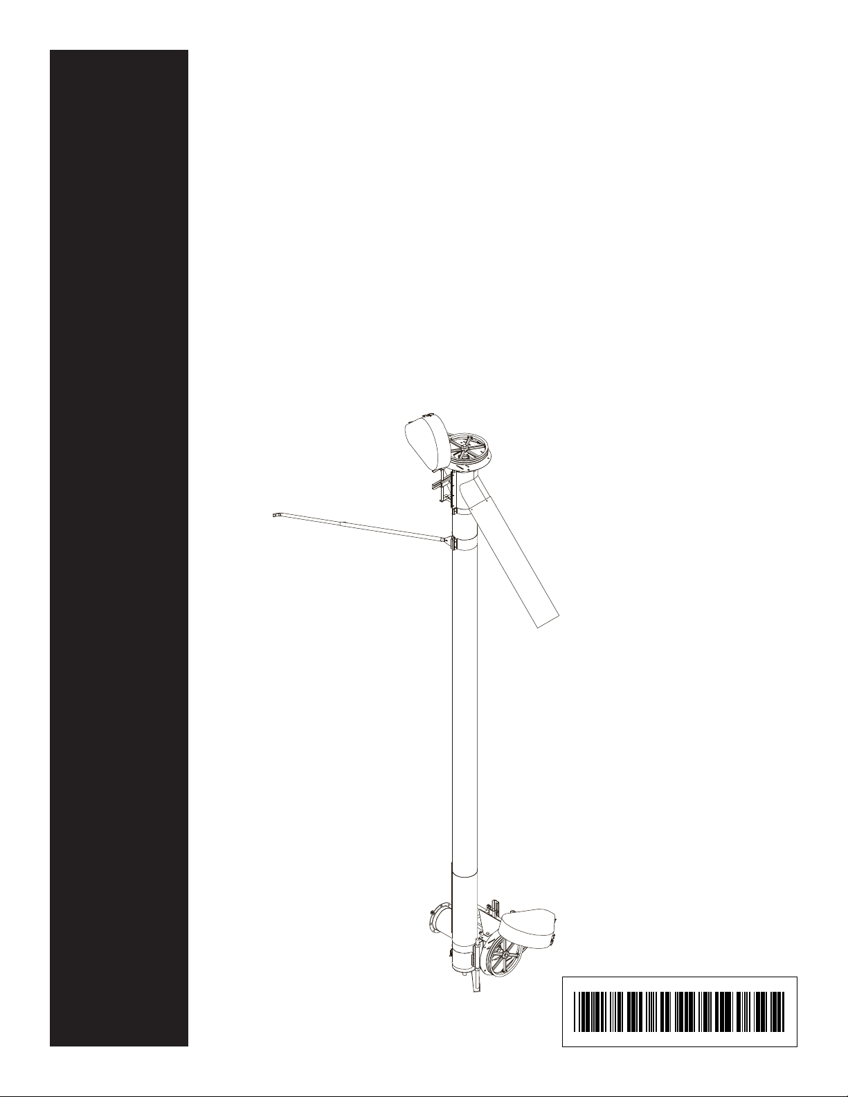
8" and 10"
Commercial Vertical
Bin Unload Auger
Assembly & Operation Manual
8" and 10" Commercial
Vertical Bin Unload Auger
PNEG-1057
07-19-10
Revision No. 1
PNEG-1057
Page 2
SAFETY GUIDELINES
This manual contains information that is important for you, the owner/operator , to know and
understand. This information relates to protecting personal safety and preventing
equipment problems. It is the responsibility of the owner/operator to inform anyone
operating or working in the area of this equipment of these safety guidelines. T o help you
recognize this information, we use the symbols that are defined below.
Please read the manual and pay attention to these sections. Failure to read this manual
and it’s safety instructions is a misuse of the equipment and may lead to serious injury or death.
This is the safety alert symbol. It is used to alert you
to potential personal injury hazards. Obey all
safety messages that follow this symbol to avoid possible
injury or death.
DANGER indicates an imminently hazardous situation which, if
not avoided, will result in death or serious injury .
WARNING indicates a potentially hazardous situation which, if
not avoided, could result in death or serious injury .
CAUTION indicates a potentially hazardous situation which, if
not avoided, may result in minor or moderate injury .
CAUTION used without the safety alert symbol indicates a
potentially hazardous situation which, if not avoided, may
result in property damage.
NOTE indicates information about the equipment that you
should pay special attention to.
Page 3

SAFETY GUIDELINES
1. General Safety Guidelines
A. DO NOT make any alterations to the equipment. Such alterations may produce a very dangerous situation,
where SERIOUS INJURY or DEATH may occur.
B. This equipment shall be installed in accordance with any regulations or installation codes that are required
by law. Authorities having jurisdiction should be consulted before installations are made.
C. Untrained operators subject themselves and others to SERIOUS INJURY or DEATH. NEVER allow
untrained personnel to operate this equipment.
D. Keep children and other unqualified personnel out of the working area at ALL times.
E. NEVER start equipment until ALL persons are clear of the work area.
F. Be sure ALL operators are adequately rested and prepared to perform ALL functions of operating this
equipment.
Safety
G . Keep hair, loose clothing, and shoestrings away from rotating and moving parts. NEVER wear loose fitting
clothing when working around augers.
H. NEVER allow any person intoxicated or under the influence of alcohol or drugs to operate the equipment.
I. NEVER allow anyone inside a bin, truck, or wagon which is being unloaded by an auger or conveyor.
Flowing grain can trap and suffocate in seconds.
J. Make sure someone is nearby who is aware of the proper shutdown sequence in the event of an accident or
emergency.
K. NEVER work alone.
L. ALWAYS think before acting. NEVER act impulsively around the equipment.
M. Make sure ALL equipment is locked in position before operating.
N. Keep hands and feet away from the auger intake and other moving parts.
O. NEVER attempt to assist machinery operation or to remove trash from equipment while in operation.
P. NEVER drive, stand, or walk under the equipment.
Q. Use caution not to hit the auger when positioning the load.
R. Use ample overhead lighting after sunset to light the work area.
S. ALWAYS lockout ALL power to the equipment when finished unloading.
T. Keep area around intake free of obstacles such as electrical cords, blocks, etc. that might trip workers.
ii
Page 4
Safety
SAFETY GUIDELINES
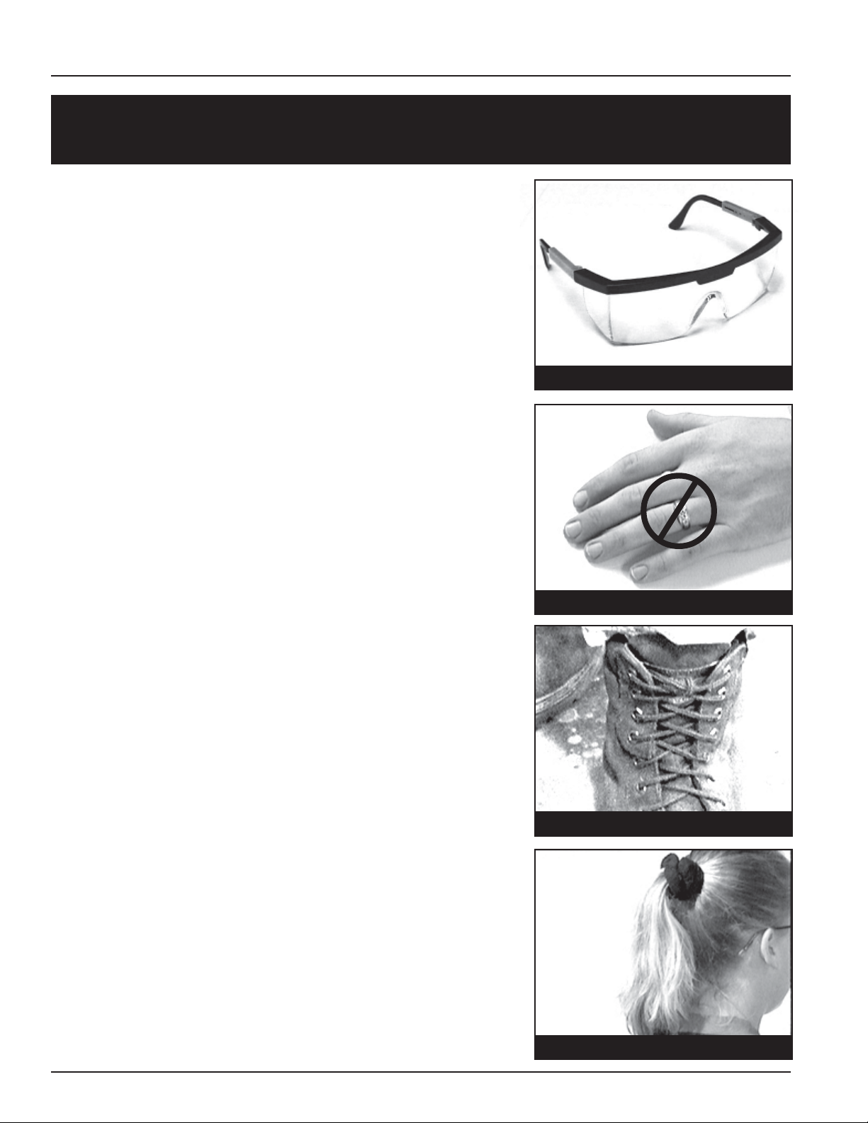
2. Personal Protective Equipment
A. The proper personal protective equipment should be worn at
ALL times by anyone in the work area.
B. ALWAYS wear safety glasses when in the work area.
C. The operator should NEVER wear jewelry.
D. Loose clothing should not be worn. Any clothing that becomes
loosened should be tucked in tightly .
2-B
2-C
E. Loose or dangling shoe strings should be tucked in.
F. Long hair should be tied up and/or back.
2-D, E
2-F
iii
Page 5
SAFETY GUIDELINES
3. Emergency Shutdown Sequence
A. In an emergency , shutdown the power source.
4. Pinch Points
A Pinch Point is any place on the equipment which can injure the operator.
A. Components of this equipment have sharp edges which can scrape and/or cut an operator.
B. A moving auger can sever an operator’s limbs or even kill him/her.
5. Shields and Guards
Safety
A. ALWAYS keep ALL shields and guards in place during operation.
We will replace any missing shields or guards free of charge!
See (page VI) for more information on our Safety First program.
6. Operator Qualifications
A. The User/Operator must be competent and experienced to operate auger equipment. Anyone who works with
or around augers must have good common sense in order to be qualified. These persons must also know and
meet all other qualifications, such as:
1. Any person who has not read and/or does not understand all operation and safety
procedures is not qualified to operate any auger systems.
2. Certain regulations apply to personnel operating power machinery . Personnel under
the age of 18 years may not operate power machinery , including augers. It is your
responsibility , as owner and/or supervisor , to know what these regulations are in your
area or situation.
3. Unqualified or incompetent persons are to remain out of the work area.
4. O.S.H.A. (Occupational Safety & Health Administration) regulations state:
"At the time of initial assignment and at least annually thereafter , the employer shall
instruct every employee in the safe operation and servicing of all equipment with
which the employee is, or will be involved." (Federal Occupational Safety & Health
Standards for Agriculture. Subpart D, Section 19287.57 (a) (6).
iv
Page 6

Safety
SAFETY GUIDELINES
6. Operator Qualifications (cont.)
B. As a requirement of OSHA, it is necessary for the employer to train the employee in the safe operating and
safety procedures for this auger. W e included this sign-of f sheet for your convenience and personal record
keeping. All unqualified persons are to stay out of the work area at all times. It is strongly recommended that
another qualified person who knows the shutdown procedure is in the area in the event of an emergency. A
person who has not read this manual and understands all operating and safety instructions is not qualified to
operate the machine.
Date Employer’s Signature Employee Signature
DATE EMPLOYER' S S I GNATURE EMPLOYEE' S S I GNATURE
1
2
3
4
5
6
7
8
9
10
11
12
13
14
15
16
17
18
19
20
21
22
v
Page 7
Safety 1st
SAFETY GUIDELINES
Our equipment is built to provide
many years of dependable service to
our customers through durable
craftsmanship.
One of the most important aspects of
our engineering is SAFETY 1
throughout all product lines. At our
company - safety is NO ACCIDENT!
That is why we have implemented a
SAFETY 1st program. Should you ever
need guards, shields, safety decals or
owner/operator manuals, simply contact
us or your local dealer, and we will
supply you with them FREE OF
CHARGE!
While it is our main goal for our
company to be the world leader in
auger manufacturing, it is always
our first priority to keep our
customers safe.
st
design
We replace missing guards and shields
FREE OF CHARGE!
If you need any of the above listed safety items or have any safety questions,
please contact the manufacturer or your local dealer .
vi
Page 8
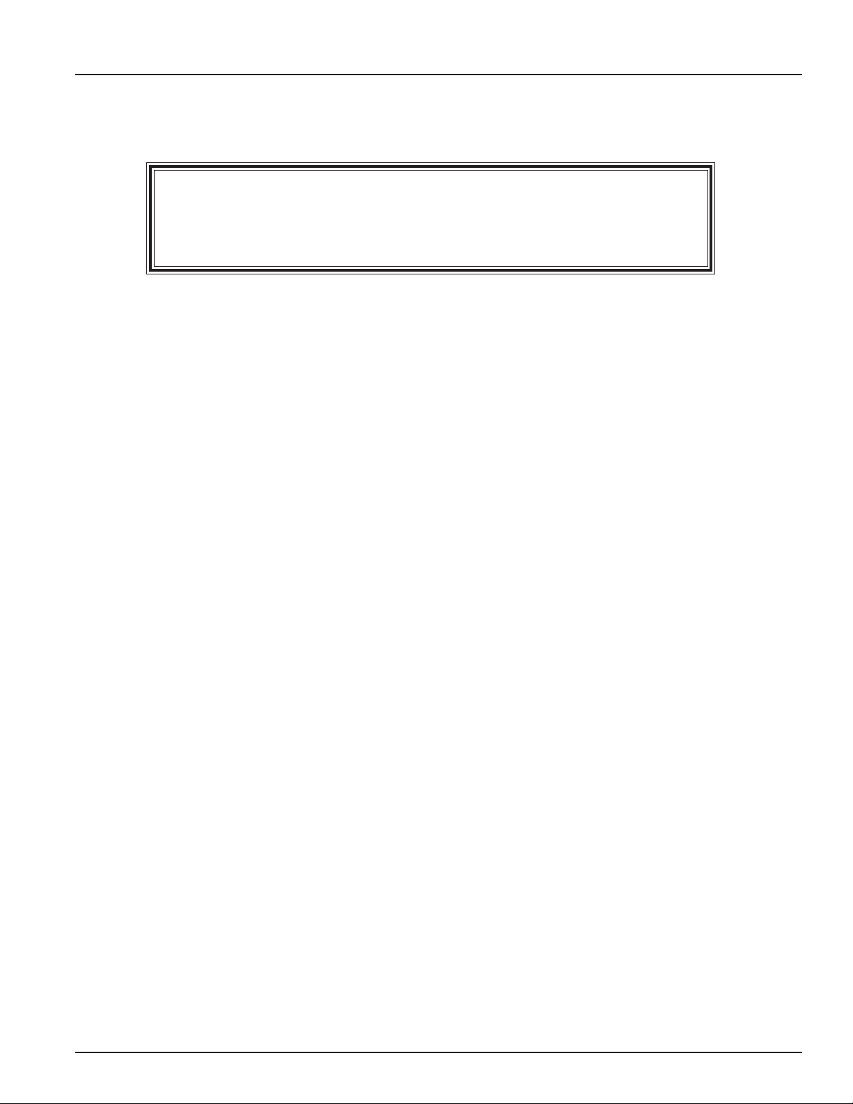
Table of Contents
Personnel operating or working around this equipment should read this
manual. This manual must be delivered with equipment to it s owner.
Failure to read this manual and its safety instructions is a misuse of the
equipment. Any misuse of the equipment may void the warranty.
Safety Guidelines ..................................................................................... i
SAFETY 1
Table of Contents ..................................................................................... vii
Decals........................................................................................................ 1
st
................................................................................................ vi
Introduction .............................................................................................. 4
8" Vertical Assembly ................................................................................ 5
10" Vertical Assembly .............................................................................. 10
Operation & Maintenance ........................................................................ 16
Startup ....................................................................................................... 15
Shutdown.................................................................................................. 19
Troubleshooting ....................................................................................... 20
8" Parts List .............................................................................................. 21
10" Parts List ............................................................................................ 23
Warranty
vii
Page 9
PNEG 1057 - 8" & 10" Commercial Vertical Bin Unloading Auger
Safety Decals
A. The image below shows the location of the decals and safety signs which should appear on the Commercial
Vertical Bin Unload Auger . Samples and explanations of these decals are shown on page 2.
2
4
Decals
1
4
3
2
2
4
1
1
Please remember safety signs provide important safety information for people working
near bin unloading equipment that is in operation. Any safety signs that are worn,
missing, illegible or painted over should be replaced immediately. Obtain FREE
replacements by contacting your dealer.
1
Page 10
Decals
t
8" & 10" Commercial Vertical Bin Unloading Auger - PNEG 1057
Safety Decals
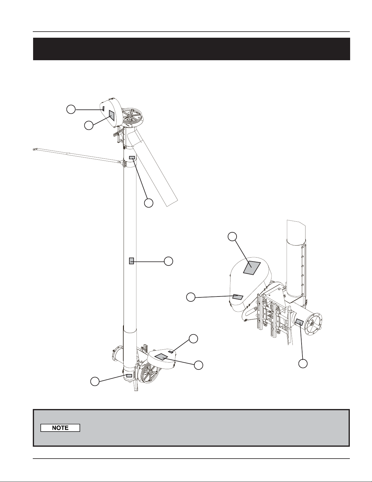
The Safety Decals chart below lists all the safety decals that should be included with the auger . Inspect all decals and
replace any that are illegible, worn, or missing. Contact your dealer or the manufacturer to order replacement decals.
Ref. # Part # Qty. Descr iption Size
1 DC-1381 1
2 DC-995 1
3 DC-1234 1
4 DC-1379 1
1
2
3
!
CAUTION
FAILURE TO PROPERLY SELECT,
INSTALL OR MAINTAIN AN AUGER, ITS
DRIVE OR OTHER COMPONENTS CAN
RESULT IN DANGEROUS OPERATION.
THIS EQUIPMENT IF IMPROPERLY
SELECTED, INSTALLED OR MAINTAINED MAY FAIL AND COULD RESULT
IN SERIOUS INJURY OR PROPERTY
DAMAGE.
CHECK PRODUCT LITERATURE
AND EQUIPMENT MANUFACTURER'S
LITERATURE OR CALL THE FACTORY
FOR FURTHER INFORMATION.
SHEAR POINT
Keep clear of rotating auger and
moving parts.
Do not remove or modify guards.
Disconnect and lock out power
before servicing.
Failure to do so will result in
serious INJURY or DEATH.
SHEAR POINT
Keep hands clear of moving
parts. Do not operate with
guard removed. Disconnec
and lockout power before
servicing.
DC-1234
DC-1381
DC-995
Safety Decals
Danger - Shear Point
Warning—Shear Point
Caution
Notice
4
1. READ AND UNDERSTAND THE OPERATOR’S MANUAL AND
2. DO NOT OPERATE WHILE UNDER THE INFLUENCE OF
3. DO NOT OPERATE UNLESS ALL SAFETY EQUIPMENT,
4. ALLOW ONLY TRAINED AUTHORIZED PERSONNEL IN THE
5. ANY ELECTRICAL WIRING OR SERVICE WORK MUST BE
6. DO NOT ALLOW CHILDREN IN THE AREA OF OPERATION.
7. KEEP HANDS, FEET AND CLOTHING AWAY FROM MOVING
8. DISCONNECT AND LOCKOUT POWER BEFORE MAKING ANY
9. DISCONNECT POWER PRIOR TO RESETTING ANY MOTOR
10. MAKE CERTAIN ALL ELECTRIC MOTORS ARE GROUNDED.
11. REPLACE ALL WORN OR DAMAGED LABELS IMMEDIATELY.
4-1/ 2" x 2"
4-1/ 2" x 2"
2-1/ 4" x 2-3/4"
5-1/ 8" x 7-3/8"
ALL SAFETY INSTRUCTIONS.
DRUGS OR ALCOHOL.
SWITCHES, GUARDS AND SHIELDS ARE SECURELY IN
PLACE AND OPERATIONAL.
OPERATING AREA.
PERFORMED BY A QUALIFIED ELECTRICIAN. IT MUST
MEET ALL STATE AND LOCAL ELECTRICAL CODES.
PARTS.
ADJUSTMENTS OR PERFORMING ANY SERVICE WORK.
OVERLOAD.
2
Page 11
PNEG 1057 - 8" & 10" Commercial Vertical Bin Unloading Auger
Decals
Safety Decals
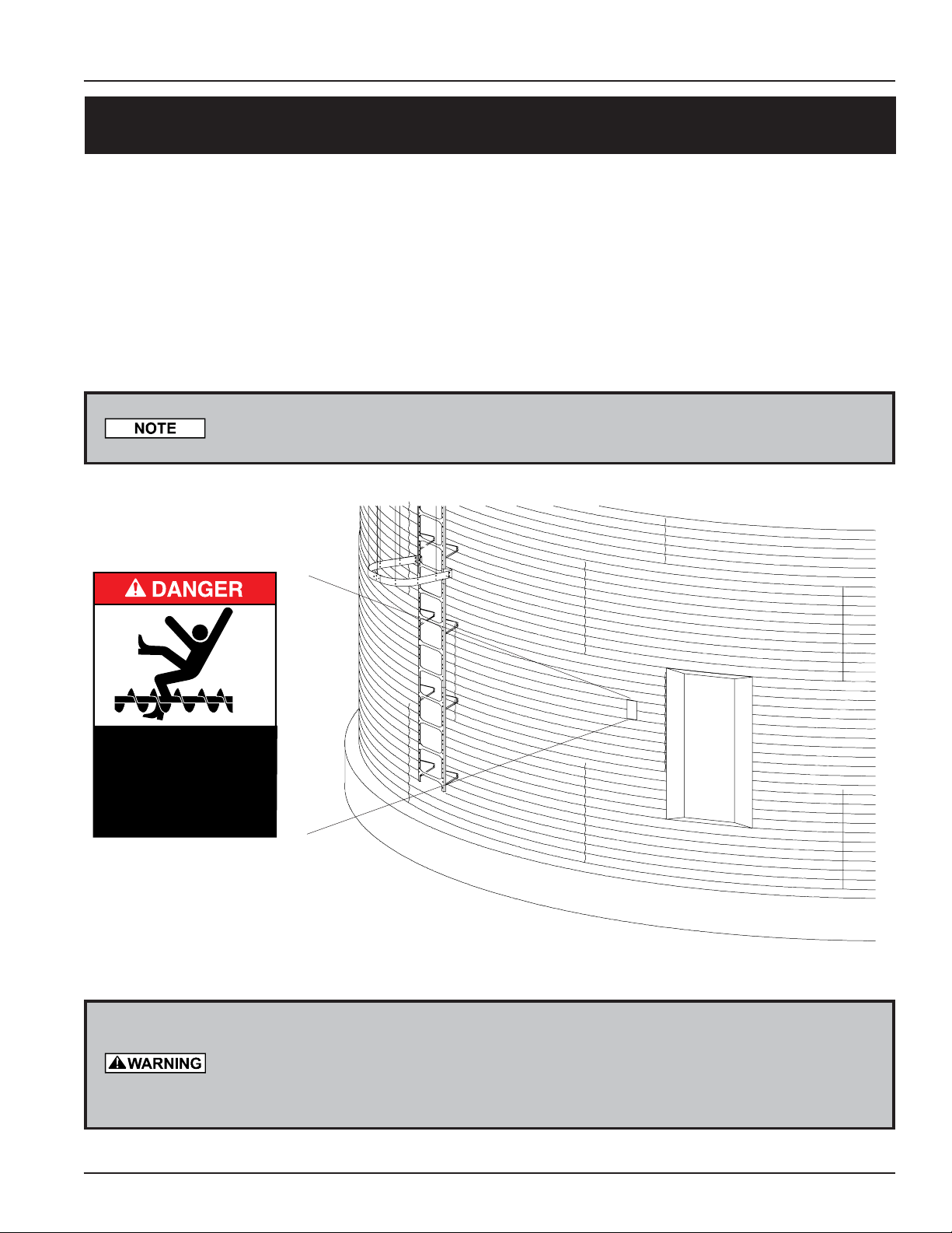
A. DANGER Sign No. DC-1395 was supplied with your bin unloading equipment. This safety sign should be applied
to the side of the bin near the bin opening, so it will be viewed by people entering into the bin storage building.
Do not cover any safety signs or any other signs that are already there.
B. If the safety sign location suggested is not in full view because of equipment modifications, other equipment in
the area, or any reason, then locate the safety sign in a more suitable location.
C. Be certain the surface is clean, dry and free of dirt and oil. Peel paper backing from decals and stick into place.
The adhesive backing will bond on contact.
Please remember, safety signs provide important safety information for people
working near bin unloading equipment that is in operation.
ROTATING FLIGHTING!
THIS BIN IS EQUIPPED WITH GRAIN AUGERS
WHICH CAN KILL OR DISMEMBER.
KEEP CLEAR OF ALL AUGERS AND NEVER ENTER
THIS BIN UNLESS ALL POWER IS
DISCONNECTED AND LOCKED OUT.
FAILURE TO DO SO WILL RESUL T IN
SERIOUS INJURY OR DEATH!
DC-1395
If the Safety Sign cannot be easily read for any reason or has been p ainted over,
replace it immediately. Additional Safety Signs may be obtained free of charge from
your dealer, distributor, or ordered from the factory.
Order SAFETY SIGN NO. DC-1395
3
Page 12

Introduction
1. General Information
A. We reserve the right to improve our product whenever possible and practical to do so. We
reserve the right to change, improve, and modify products at any time without obligation to
make changes, improvements, and modifications on equipment sold previously .
B. The 8" & 10" Commercial Vertical Bin Unload Augers have been designed and manufactured
to give years of dependable service. The care and maintenance of this machine will affect the
satisfaction and service obtained. By observing the instructions and suggestions we have
recommended, the owner should receive competent service for many years. If additional
information or assistance should be required, please contact the factory or your local dealer.
C. When receiving merchandise, it is important to check both the quantity of parts and their
descriptions with the packing list enclosed within each package. All claims for freight
damage or shortage must be made by the consignee within ten (10) days from the date of the
occurrence of freight damage. The consignee should accept the shipment after noting the
damage or loss.
2. Capacity
8" & 10" Commercial Vertical Bin Unloading Auger - PNEG 1057
A. The capacities may vary greatly under varying conditions. The following factors play a role
in the performance of the auger:
• Speed • Amounts of foreign matter
• Angle of operation • Different materials
• Moisture content • Methods of feeding
B. For example, a twenty-five percent (25%) moisture could cut capacity by as much as
40% under some conditions.
4
Page 13

PNEG 1057 - 8" & 10" Commercial Vertical Bin Unloading Auger
8" Vertical Assembly
1. Motor Mount Rod to Head Plate Assembly
A. Screw one 3/4" hex head nut to the top of each motor mount rod (10).
B. Slide the motor mount rods (10) through the head plate assembly (1 1).
C. Line up slot on the plate end of the motor mount rods (10) with the slot on the head plate assembly (11). Fasten
them together using 5/16" carriage bolt, a flat washer, and a nut.
D. Attach a 3/4" hex head nut onto the bottom of each motor mount rod. Tighten until nut rests against the head
plate assembly (1 1).
E. Adjust top 3/4" hex head nuts down until they rests against the top of the head plate assembly (11).
2. Tube Assembly
A. Connect the two-hole flange bearing (12) to head plate assembly (1 1) using two 7/16" x 1-1/4" bolts
with locknuts.
B. Loosen the top and bottom nuts on the head plate assembly (1 1) to allow the belt guard mounting angles (35)
to slide onto the motor mount rods (10). Once the angles are in place tighten nuts to keep rods in position.
C. Connect head drive shaft (13) to flight using two 7/16" x 2-1/4" (grade 5) bolts with locknuts.
D. Slide head plate assembly (1 1) over discharge end of tube and tighten the halfband clamp s (5) using four
5/16" x 1-1/2" bolts with nuts. Slip bearing lock collar (not shown) over head drive stub.
E. Fasten belt guard (17) to top mounting angle (35) using two 5/16" x 3/4" carriage bolts with flat washers,
lockwashers, and nuts.
Leave carriage bolts loose until later.
F. Place head drive shaft (13) through head bearing with enough extended to mount pulley (18) with key (37).
Tighten lock collar on bearing and tighten setscrews in pulley .
G . Install motor and pulley onto motor mount. (Motor and pulley are not included.) Install belts (3) and tighten
by adjusting motor height by using the four 3/4" nuts on the rods.
H. Close door on belt guard and latch.
I. Secure 45° discharge spout (6) Over the discharge opening using the head plate assembly and eight
5/16" x 1-1/2" long bolts with nuts.
5
Page 14

8" Vertical Assembly
8" Vertical Tube Assembly
7
10
8" & 10" Commercial Vertical Bin Unloading Auger - PNEG 1057
3
17
35
13
11
37
8
5
11
17
12
4
6
35
18
Lock out all power sources while installing or maintaining equipment.
Keep all safety devices and shields in place at all times until power source is locked out.
6
Page 15

PNEG 1057 - 8" & 10" Commercial Vertical Bin Unloading Auger
8" Vertical Assembly
3. Attaching Vertical Section to Bin
A. Slide bin unloading flight into bin well and unloading tube (which should already be installed in bin.)
The unloading flight for larger bin sizes may need to be bolted together . Use bolts provided in connecting stubs
located at the end of the tail flights. See the 8" Flight Chart below to determine the flight length for your bin size.
B. Bolt unloading flight to short horizontal flight (#3 on page 9) using four 7/16" x 2-3/4" long (grade 5) bolts
and locknuts.
C. Bolt flange on horizontal tube of vertical unloader to the flange of the bin unloader tube with vertical auger in
vertical position. Use eight 5/16" x 1" long bolts, lockwashers, and nuts.
8" FLIGHT CHART
Product No. Bin Dia. Part No.
GFC82400
GFC82700 27' GK1800 16' -0" x 7" O.D. Flight
GFC83000 30' GK1801 17' -6" x 7" O.D. Flight
GFC83300 33'-34' GK1802 19' -6" x 7" O.D. Flight
GFC83600 36' GK1803 20' -6" x 7" O.D. Flight
GFC83800 37'-39' GK1804 22' -6" x 7" O.D. Flight
GFC84000 40' GK1805 23' -0" x 7" O.D. Flight
GFC84200 42' GK1806 24' -0" x 7" O.D. Flight
GFC84800 48'-49' GK1808 20' -0" x 7" O.D. Flight (Head)
GFC85400
GFC86000
GFC86300
GFC86800
GFC87200
GFC87500
GFC87800
GFC88000 80' GK1808 20' -0" x 7" O.D. Flight (Head)
GFC88200 82' GK1808 20' -0" x 7" O.D. Flight (Head)
GFC89000 90' GK1808 20' -0" x 7" O.D. Flight (Head)
GFC89200 92' GK1808 20' -0" x 7" O.D. Flight (Head)
24'
54'-55' GK1808 20' -0" x 7" O.D. Flight (Head)
60' GK1808 20' -0" x 7" O.D. Flight (Head)
63' GK1808 20' -0" x 7" O.D. Flight (Head)
68'-69' GK1808 20' -0" x 7" O.D. Flight (Head)
72' GK1808 20' -0" x 7" O.D. Flight (Head)
75' GK1808 20' -0" x 7" O.D. Flight (Head)
78' GK1808 20' -0" x 7" O.D. Flight (Head)
GK1799 14' -6" x 7" O.D. Flight
GK1807 7' -0" x 7" O.D. Flight (Tail)
GK1809 10' -0" x 7" O.D. Flight (Tail)
GK1810 13' -0" x 7" O.D. Flight (Tail)
GK1811 14' -6" x 7" O.D. Flight (Tail)
GK1812 17' -0" x 7" O.D. Flight (Tail)
GK1813 19' -0" x 7" O.D. Flight (Tail)
GK1814 20' -6" x 7" O.D. Flight (Tail)
GK1815 22' -6" x 7" O.D. Flight (Tail)
GK1130 20' -0" x 7" O.D. Flight (Middle)
GK1821 4' -6" x 7" O.D. Flight (Tail)
GK1130 20' -0" x 7" O.D. Flight (Middle)
GK1823 5' -6" x 7" O.D. Flight (Tail)
GK1130 20' -0" x 7" O.D. Flight (Middle)
GK1824 9' -6" x 7" O.D. Flight (Tail)
GK1130 20' -0" x 7" O.D. Flight (Middle)
GK1825 10' -6" x 7" O.D. Flight (Tail)
Description
7
Page 16

8" Vertical Assembly
8" & 10" Commercial Vertical Bin Unloading Auger - PNEG 1057
3. Attaching Vertical Section to Bin (cont.)
D. Adjust stand (#40 on page 9) so it holds the weight of the vertical auger .
E. Attach the support brackets and halfbands to the top half of the vertical tube by inserting the 5/16" U-bolt (4)
through the support brackets (5) and halfbands (6) and fasten together using four 5/16" nylon locknuts.
F. Attach lower telescoping tube sections (3) to the ears on the support brackets (5) using two
3/8" x 3/4" bolts with locknuts.
G . Slide the upper telescoping tube sections (1) into the lower tube sections (3). Attach upper tubes to the bin wall.
H. Secure the upper telescoping tubes to the lower telescoping tubes by tightening the square head setscrew (2).
1
1
2
3
4
5
6
4. Attaching Motor Mount to Horizontal Section
A. First, connect the head stub shaft (13) to the short flight (3) using two 7/16" x 2-3/4" (grade 5)
bolts with locknuts.
B. Connect the four-hole flange bearing with lock collar (4) and the head plate (28) together using four
7/16" x 1-1/4" bolts with locknuts.
C. Attach the head plate (28) to the tube flange using eight 5/16" x 1" bolts with flat washers,
lockwashers, and nuts.
7
D. Connect side plates (22) and (23) to head plate (28) using four 1/2" x 1" bolts with lockwashers
and nuts. Also, at the same time attach the top and bottom belt guard bracket s (27) using the same bolts.
E. Spin a 3/4" nut on the threaded rods of each strap and rod assembly (24). Insert threaded rods through holes in
side plates (22) & (23) and add four more 3/4" nuts. Leave only finger tight until later .
F. Place rods (26) in strap and rod assemblies (24) and secure with top straps (25) using
3/8" x 1-1/2" bolts with two flat washers and one nut on each bolt.
8
Page 17

PNEG 1057 - 8" & 10" Commercial Vertical Bin Unloading Auger
G . Position motor mount straps (15) and clips (14) and secure to rod (26) using four 3/8" x 3" long carriage bolts
with nuts. Leave only finger tight until motor is installed and adjusted.
H. Attach belt guard (17) to belt guard mounting angles (27) using four 5/16" x 3/4" carriage bolts with flat washers
and nuts.
I. Slide bearing lock collar (4) over head stub shaft (13). Leave enough stub exposed to mount
pulley (18) on stub with drive key (37). Tighten bearing lock collar next to bearing and tighten set screws
in pulley .
J. Install pulley on head stub shaft and mount motor on strap (15). (Motor and pulley not furnished.) Install
belts (2) and align pulleys. T ighten motor to straps (15). Adjust motors along the tube and tighten with 3/8" x 3"
carriage bolts.
K. After everything has been adjusted correctly, go back and tighten all nuts and bolts.
8" Vertical Assembly
25
23
24
3
13
40
22
26
14
14
24
27
28
4
37
15
15
26
17
2
27
17
18
9
Page 18

10" Vertical Assembly
8" & 10" Commercial Vertical Bin Unloading Auger - PNEG 1057
5. Motor Mount Rod to Head Plate Assembly
A. Screw one 7/8" hex head nut to the top of each motor mount rod (13).
B. Slide the motor mount rods through the head plate assembly .
C. Line up slot on the plate end of the motor mount rods (13) with the slot on the head plate assembly (7). Fasten
them together using 3/8" carriage bolt, a split flat washer, and a nut.
D. Attach a 7/8" hex head nut onto the bottom of each motor mount rod. Tighten until nut rests against the head
plate assembly (7).
E. Adjust top 7/8" hex head nuts down until they rests against the top of the head plate assembly (7).
6. Tube Assembly
A. Connect the four-hole flange bearing (16) to head plate assembly (7) using four 1/2" x 1-1/2" bolts with locknuts.
B. Loosen the top and bottom nuts on the head plate assembly (7) to allow the belt guard mounting angles (17) to
slide onto the motor mount rods (13). Once the angles are in place tighten nuts to keep rods in position.
C. Connect head drive stub shaft (18) to flight using two 1/2" x 3.5" (grade 5) bolts with locknuts.
D. Slide head plate assembly (7) over discharge end of tube and tighten the halfband clamps (9) using four
5/16" x 1-3/4" bolts with nuts. Slip bearing lock collar (not shown) over head drive stub.
E. Fasten belt guard (20) to top mounting angle (17) using two 5/16" x 3/4" carriage bolts with flat washers,
lockwashers, and nuts.
Leave carriage bolts loose until later.
F. Place head drive stub shaft (18) through head bearing with enough extended to mount pulley (19) with key (3).
Tighten bearing with lock collar and tighten setscrews in pulley.
G . Install motor and pulley onto motor mount. (Motor and pulley are not included.) Install belts (2) and tighten
by adjusting motor height by using the four 3/4" nuts on the rods.
H. Close door on belt guard and latch.
I. Secure 45° discharge spout (57) Over the discharge opening using the head plate assembly and eight
5/16" x 1-1/2" long bolts with nuts.
J. After everything has been adjusted, go back and tighten all nuts and bolts.
10
Page 19

PNEG 1057 - 8" & 10" Commercial Vertical Bin Unloading Auger
10" Vertical Tube Assembly
13
15
10" Vertical Assembly
2
17
19
14
18
20
9
3
7
57
16
17
Lock out all power sources while installing or maintaining equipment.
Keep all safety devices and shields in place at all times until power source is locked out.
11
Page 20

10" Vertical Assembly
8" & 10" Commercial Vertical Bin Unloading Auger - PNEG 1057
7. Attaching Vertical Section to Bin
A. Slide bin unloading flight into bin well and unloading tube (which should already be installed in bin.)
The unloading flight for larger bin sizes may need to be bolted together . Use bolts provided in connecting stubs
located at the end of the tail flights. See the 8" Flight Chart below to determine the flight length for your bin size.
B. Bolt unloading flight to short horizontal flight (#6 on page 14) using four 1/2" x 3" long (grade 5) bolts
and locknuts.
C. Bolt flange on horizontal tube of vertical unloader to the flange of the bin unloader tube with vertical auger in
vertical position. Use eight 5/16" x 1" long bolts, lockwashers, and nuts.
10" FLIGHT CHART
Product No. Bin Dia. Part No.
'
GFC10240
GFC10270
GFC10300
GFC10330
GFC10360
GFC10380
GFC10400
GFC10420
GFC10480
GFC10540
GFC10600 60' GK1835 20' -0" x 7" O.D. Flight (Head)
GFC10630 63' GK1835 20' -0" x 7" O.D. Flight (Head)
GFC10680 68'-69' GK1835 20' -0" x 7" O.D. Flight (Head)
GFC10720 72' GK1835 20' -0" x 7" O.D. Flight (Head)
GFC10750 75' GK1835 20' -0" x 7" O.D. Flight (Head)
GFC10780 78' GK1835 20' -0" x 7" O.D. Flight (Head)
GFC10800
GFC10820
GFC10900
GFC10920
24
27' GK1827 16' -0" x 7" O.D. Flight
30' GK1828 17' -6" x 7" O.D. Flight
33'-34' GK1829 19' -6" x 7" O.D. Flight
36' GK1830 20' -6" x 7" O.D. Flight
37'-39' GK1831 22' -6" x 7" O.D. Flight
40' GK1832 23' -0" x 7" O.D. Flight
42' GK1833 24' -0" x 7" O.D. Flight
48'-49' GK1835 20' -0" x 7" O.D. Flight (Head)
54'-55' GK1835 20' -0" x 7" O.D. Flight (Head)
80' GK1835 20' -0" x 7" O.D. Flight (Head)
82' GK1835 20' -0" x 7" O.D. Flight (Head)
90' GK1835 20' -0" x 7" O.D. Flight (Head)
92' GK1835 20' -0" x 7" O.D. Flight (Head)
GK1826 14' -6" x 7" O.D. Flight
GK1834 7' -0" x 7" O.D. Flight (Tail)
GK1836 10' -0" x 7" O.D. Flight (Tail)
GK1837 13' -0" x 7" O.D. Flight (Tail)
GK1838 14' -6" x 7" O.D. Flight (Tail)
GK1839 17' -0" x 7" O.D. Flight (Tail)
GK1840 19' -0" x 7" O.D. Flight (Tail)
GK1841 20' -6" x 7" O.D. Flight (Tail)
GK1842 22' -6" x 7" O.D. Flight (Tail)
GK1844 20' -0" x 7" O.D. Flight (Middle)
GK1843 4' -6" x 7" O.D. Flight (Tail)
GK1844 20' -0" x 7" O.D. Flight (Middle)
GK1845 5' -6" x 7" O.D. Flight (Tail)
GK1844 20' -0" x 7" O.D. Flight (Middle)
GK1846 9' -6" x 7" O.D. Flight (Tail)
GK1844 20' -0" x 7" O.D. Flight (Middle)
GK1847 10' -6" x 7" O.D. Flight (Tail)
Description
12
Page 21

PNEG 1057 - 8" & 10" Commercial Vertical Bin Unloading Auger
10" Vertical Assembly
7. Attaching Vertical Section to Bin (cont.)
D. Adjust stand (#47 on page 14) so it holds the weight of the vertical auger .
E. Attach the support brackets and halfbands to the top half of the vertical tube by inserting the 5/16" U-bolt (4)
through the support brackets (5) and halfbands (6) and fasten together using four 5/16" nylon locknuts.
F. Attach lower telescoping tube sections (3) to the ears on the support brackets (5) using two
3/8" x 3/4" bolts with locknuts.
G . Slide the upper telescoping tube sections (1) into the lower tube sections (3). Attach upper tubes to the bin wall.
H. Secure the upper telescoping tubes to the lower telescoping tubes by tightening the square head setscrew (2).
1
1
2
3
4
5
6
8. Attaching Horizontal Motor Mount (Direct Belt Drive)
A. First, connect the head stub shaft (39) to the short flight (6) using two 1/2" x 3" (grade 5)
bolts with locknuts.
B. Connect the four-hole flange bearing with lock collar (16) to the head plate (8) together using four
1/2" x 1-1/2" bolts with locknuts.
C. Attach the head plate (8) to the tube flange using eight 5/16" x 1" bolts with flat washers,
lockwashers, and nuts.
D. Connect side plates (22) and (23) to head plate (8) using four 1/2" x 1-1/4" bolts with lockwashers
and nuts. Also, at the same time, attach the belt guard brackets (21) using the same bolts.
7
E. Spin a 3/4" nut on the threaded rods of each strap and rod assembly (24). Insert threaded rods through holes in
side plates (22) & (23) and add four more 3/4" nuts. Leave only finger tight until later .
F. Place rods (25) in strap and rod assemblies (24) and secure with top straps (26) using
3/8" x 1-1/2" bolts with two flat washers and one nut on each bolt.
13
Page 22

10" Vertical Assembly
G . Clamp belt guard mounting angle (30) to rod ends (25) with clamp bar (31) using four 5/16" x 1-3/4" bolts
with nuts.
H. Attach belt guard back (28) to belt guard mounting angles (21) using four 5/16" x 3/4" carriage bolts with flat
washers and nuts.
I. Slide bearing lock collar (40) over head stub shaft (39). Leave enough stub exposed to mount pulley (21) on stub
with drive key (41). Tighten bearing lock collar next to bearing and tighten set screws in pulley.
J. Position motor mount straps (15) and clips (14) and secure using four 3/8" x 3" carriage bolts and nuts. Leave
finger tight until later .
K. Install pulley on motor shaft and mount motor on strap (15). (Motor and pulley not furnished.) Install belts (3)
and align pulleys. Tighten motor to straps (15). Adjust motors along the tube and tighten with 3/8" x 3"
carriage bolts.
L. Set belt tension by adjusting height of motor using 3/4" nuts on rods.
L. Connect belt guard (29) by bolting belt guard clamp bar (33) to mounting angle (21) using 1/4" x 5-1/2" bolts
with nuts. Att ach second clamp bar (32) to belt guard mounting bracket s (30) using 1/4" x 5-1/2" bolts .
8" & 10" Commercial Vertical Bin Unloading Auger - PNEG 1057
21
40
41
15
30
25
15
31
28
27
3
6
39
5
47
22
6
25
26
6
14
24
8
21
16
14
29
33
32
Page 23

PNEG 1057 - 8" & 10" Commercial Vertical Bin Unloading Auger
1. Start-up and Break-In
ALWAYS keep ALL guards and shields in place, until all the power is disconnected
and locked out.
A. Make sure all belts are tensioned properly.
B. Make sure ALL shields are in place and that the belt(s) and pulley(s) are able to move freely.
C. Double check the assembly instructions to see that all parts have been assembled properly .
D. During operation of equipment, one person should be in a position to monitor the entire operation.
During the initial start-up and break-in period, the operator should note any unusual
vibrations or noises and take the appropriate action.
Make certain everyone is clear before operating or moving the machine.
Start-up
E. The bin well inside the bin should have a control gate. The gate should be closed before start-up and closed
before shutdown to allow the machine to clean out.
F. The controls for the control gate should either pull or push open, depending on the type of well you have. Use the
control gate to regulate a flow of less than full capacity until several hundred bushels of grain have been augered
to polish the flighting assembly and tube.
G. Any new screw conveyor or one that has set idle for a season should go through a “break-in” period. This
“break-in” consists of running the auger at half capacity until the screw becomes polished and smooth before
attempting to run at full capacity . It is recommended that several hundred bushels of grain be augered at
partial capacity.
Failure of your auger is very likely to occur if it is run at full capacity before the
screw has become polished.
NEVER operate augers empty for any length of time as excessive wear will result.
H. Do not stop or start augers under load, especially before the flight and tube become well polished, as this may
cause the auger to “lockup”. Make sure to use the control gate as a flow control so the vertical auger
cannot become plugged.
Excessive wear will result if auger is run at speeds in excess of what is recommended.
15
Page 24

Operation & Maintenance
8" & 10" Commercial Vertical Bin Unloading Auger - PNEG 1057
1. 8" Vertical Commercial Bin Unloading Auger Operating Instructions
A. Parts Included: 16’-6" vertical auger, horizont al tube 24" long with flange, horizontal drive with 2 or 3 belt drive,
2 belt vertical drive with pulleys, “B” belts, motor mount, mounting brackets, belt guard and 3' discharge spout.
Y our horizontal unloading flight should be ordered separately .
B. Capacity: For cases with high moisture or high capacity requirements, use the next size larger motor .
( See Capacity Chart Below .)
MATERIAL CAPACITY - 8"
Dry Grain 1000-1500
High Moisture 800-1200
C. Vertical Drive: Use a 4.6" motor pulley for recommended auger speed of 536 RPM.
D. Horizontal Drive: Use a 3.5" motor pulley for recommended auger speed of 408 RPM.
Motor pulleys are NOT furnished with the auger.
E. Vertical Horsepower: Use a 5 H.P. Motor
F. Horizontal Horsepower: Use the horsepower chart below to find the flight length to fit your needs.
8" Horizontal Flights for Vertical Height Unloade rs
Pr oduc t No. Bin Dia. H.P.
GFC 82400 24' 3 14' -6" x 7" O. D. F light
GFC 827 00 27' 3 1 6' -0" x 7 " O.D. F l igh t
GFC 830 00 30' 5 1 7' -6" x 7 " O.D. F l igh t
GFC83300 33'-34' 5 19' -6" x 7" O. D. F light
GFC 836 00 36' 5 2 0' -6" x 7 " O.D. F l igh t
GFC83800 37'-39' 5 22' -6" x 7" O. D. F light
GFC 840 00 40' 5 2 3' -0" x 7 " O.D. F l igh t
GFC 842 00 42' 5 2 4' -0" x 7 " O.D. F l igh t
GFC84800 48'-49' 5 27' -0" x 7" O. D. F light
GFC85400 54'-55' 5 30' -0" x 7" O. D. F light
GFC 860 00 60' 5 3 3' -0" x 7 " O.D. F l igh t
GFC 863 00 63' 5 3 4' -6" x 7 " O.D. F l igh t
GFC86800 68'-69' 7 1/2 37' -6" x 7" O. D. Flight
GFC 872 00 72' 7 1 /2 3 9' -0" x 7" O.D. F l i gh t
GFC 875 00 75' 7 1 /2 4 0' -6" x 7" O.D. F l i gh t
GFC 878 00 78' 10 42' -6" x 7" O.D. F l i ght
GFC 880 00 80' 10 44' -6" x 7" O.D. F l i ght
GFC 882 00 82' 10 45' -6" x 7" O.D. F l i ght
GFC 890 00 90' 10 49' -6" x 7" O.D. F l i ght
GFC 892 00 92' 10 50' -6" x 7" O.D. F l i ght
Flight Length
G. The horsepower recommendations are for augering reasonably dry grain. High moisture grain (above 15%) will
require greater power if maximum capacity is to be maintained. The maximum possible capacity will be less
with high moisture grain than with dry grain. Use an electric motor of the correct size that operates at
1750 R. P. M.
16
Electrical controls and wiring should be installed by a qualified electrician. The
motor disconnect switches and conductor cables should comply with the National
Electrical Code and any local codes which apply. Motor starting control stations
should be so located that the operator can see that all personnel are clear of the
equipment.
Page 25

PNEG 1057 - 8" & 10" Commercial Vertical Bin Unloading Auger
g
Operation & Maintenance
2. 10" Vertical Commercial Bin Unloading Auger Operating Instructions
A. Parts Included: 16’-6" vertical auger, horizont al tube 30" long with flange, horizontal drive with 2 or 3 belt drive,
2 belt vertical drive with pulleys, “B” section belts, motor mount, mounting brackets, belt guard and 3' discharge
spout. Y our horizont al unloading flight should be ordered separately .
B. Capacity: For cases with high moisture or high capacity requirements, use the next size larger motor .
( See Capacity Chart Below .)
MATERIAL CAPACITY - 10"
Dry Grain 1600-2000
High Moisture 1300-1600
C. Vertical Drive: Use a 4.6" motor pulley for recommended auger speed of 408 RPM.
D. Horizontal Drive: Use a 3.4" motor pulley for recommended auger speed of 323 RPM.
Motor pulleys are NOT furnished with the auger.
E. Vertical Horsepower: Use a 7-1/2 H.P. Motor
F. Horizontal Horsepower: Use the horsepower chart below to find the flight length to fit your needs.
10" Horizontal Flights for Vertical Height Unloaders
Product No. Bin Dia. H.P.
GFC10240 24
GFC10270 27' 5 16' -0" x 7" O.D. Flight
GFC10300 30' 5 17' -6" x 7" O.D. Flight
GFC10330 33'-34' 5 19' -6" x 7" O.D. Flight
GFC10360 36' 7 1/2 20' -6" x 7" O.D. Flight
GFC10380 37'-39' 7 1/2 22' -6" x 7" O.D. Flight
GFC10400 40' 7 1/2 23' -0" x 7" O.D. Flight
GFC10420 42' 7 1/2 24' -0" x 7" O.D. Flight
GFC10480 48'-49' 7 1/2 27' -0" x 7" O.D. Flight
GFC10540 54'-55' 7 1/2 30' -0" x 7" O.D. Flight
GFC10600 60' 10 33' -0" x 7" O.D. Flight
GFC10630 63' 10 34' -6" x 7" O.D. Flight
GFC10680 68'-69' 10 37' -6" x 7" O.D. Flight
GFC10720 72' 10 39' -0" x 7" O.D. Flight
GFC10750 75' 10 40' -6" x 7" O.D. Flight
GFC10780 78' 10 42' -6" x 7" O.D. Flight
GFC10800 80' 15 44' -6" x 7" O.D. Flight
GFC10820 82' 15 45' -6" x 7" O.D. Flight
GFC10900 90' 15 49' -6" x 7" O.D. Flight
GFC10920 92' 15 50' -6" x 7" O.D. Fli
'
5 14' -6" x 7" O.D. Flight
Flight Length
ht
G. The horsepower recommendations are for augering reasonably dry grain. High moisture grain (above 15%) will
require greater power if maximum capacity is to be maintained. The maximum possible capacity will be less
with high moisture grain than with dry grain. Use an electric motor of the correct size that operates at
1750 R. P. M.
Electrical controls and wiring should be installed by a qualified electrician. The motor
disconnect switches and conductor cables should comply with the National Electrical
Code and any local codes which apply. Motor starting control stations should be so
located that the operator can see that all personnel are clear of the equipment.
17
Page 26

Operation & Maintenance
8" & 10" Commercial Vertical Bin Unloading Auger - PNEG 1057
3. Power Source
A. Use electric motors that operate at 1750 R.P .M.
B. Electric motors and controls should be installed by a qualified electrician and must meet the standards set by
the National Electrical Code and all local and state codes.
C. A magnetic starter should be used to protect your motor when starting and stopping. It should stop the motor in
case of power interruption, conductor fault, low voltage, circuit interruption, or motor overload. Then the motor
must be restarted manually . Some motors have built-in thermal overload protection. If this type motor is used,
use only those with a manual reset.
You should use a Main Power Disconnect Switch capable of being locked only in the
OFF position. This should be locked whenever work is being done on the auger.
Disconnect power before resetting motor overloads.
Make sure all electrical motors are grounded.
Reset and motor starting and stopping controls must be located so that the operator has
full view of the entire operation.
Shut off power to adjust , service, or clean the machinery.
Keep all safety guards and shields in place.
4. Maintenance
A. The flange bearings on the head and tail ends of all units should be lubricated on frequent intervals.
18
Never clean, adjust, or lubricate a machine that is in operation.
Page 27

PNEG 1057 - 8" & 10" Commercial Vertical Bin Unloading Auger
1. Normal Shutdown
A. Make certain that bin well and unloading tubes are empty before stopping the unit.
B. Disconnect and lockout the power source before leaving the work area.
2. Emergency Shutdown
A. Know how to shut down the auger in case of an emergency.
B. Disconnect and lockout the power source.
C. Close bin well control gates.
D. Clear out as much grain from the auger and hopper as you can.
Never restart when under a full load. Starting unit under load may result in damage
to the machine. Such damage is considered abuse of the equipment.
Shutdown
E. Reconnect and unlock the power source.
F. Gradually clear the auger until there is no grain or obstructions.
3. Lockout
A. Always stop and disconnect the power source whenever the operator must leave the work area or for
maintenance of the machinery .
B. Make sure no one can operate the unload auger while the operator is not in the work area.
Use the type of main power disconnect switch that is capable of being locked
only in the off position.
3. Storage Preparation
A. Close all wells to discharge tube.
B. Be sure the unload tube is empty.
C. Make sure power source is disconnected and locked out.
D. Check to see that all fasteners are secure.
19
Page 28

Troubleshooting
8" & 10" Commercial Vertical Bin Unloading Auger - PNEG 1057
Problem
1. The auger is vibrating.
Possible Cause
A. Damage can occur to the
auger flighting, causing noise.
Damage usually is caused
from foreign material being run
through the auger.
A. Drive belt may be overtightened,
putting head stub and flight in a
bind.
2. Capacity is too low. A. There may not be enough grain
reaching the auger.
B. The auger is moving too slowly.
Solution
A1. It may be necessary to remove the
flighting for inspection.
A1. Loosen the drive belts.
A1. Make sure the intake has not
bridged over, restricting flow . The
flighting at the intake should be
covered with grain for maximum
capacity.
B1. Check the auger speed. Low
capacity will result from speeds
slower than recommended.
3. The auger plugs.
A. The auger may be "jamming"
because too much grain is
reaching the auger.
B. The grain may be wet. B1. If wet grain or other hard-to-move
C. The auger may be jammed
with foreign material.
D. The motor may be to small or
wired incorrectly .
A1. Use the control gates to decrease
the amount of grain the auger is
gathering.
material is being augured, use a
larger size motor than recommended for normal use.
C1. Remove any foreign material in the
auger.
D1. Check wiring or consider using the
next larger size motor .
20
Page 29

PNEG 1057 - 8" & 10" Commercial Vertical Bin Unloading Auger
8" PARTS ILLUSTRATION
18
17
35
Parts
38
12
10
7
8
20
21
15
11
25
37
6
26
13
5
43
18
23
4
45
19
13
28
17
49
50
47
24
14
22
27
48
52
53
46
39
42
41
44
40
21
Page 30

Parts
8" & 10" Commercial Vertical Bin Unloading Auger - PNEG 1057
8" PARTS LIST
Ref. No. Part No. Description
4 GK 1017 1.25" B ore Flange B earing w/ Loc k
5 GK 1055 8" x 2" Wide G alvanized Halfband
6 GK 1059 8" x 4" Wide G alvanized Halfband - 12 Ga.
7 GK 1063 Motor M ount Top S trap
8 GK 1064 Motor M ount Bott om S t rap
N/S GK1317 Decals P ac kage
10 GK 1327 8" Mot or Mount W eldm ent
11 GK 1331 Drive Shaft - 1.25" O. D. x 10. 5"
12 GK 1330 1.25" Two hole flange bearing
13 GK 1329 8" Head Plat e A s s em bly
14 GK 1341 M otor M ount B ottom
15 GK 1342 Motor M ount Top
N/S GK1346 Belt V B -57
17 GK 1454 Belt G uard As s embly
18 GK 1869 Alum inum S heave - 15" x 1.25" for 2 belts
19 GK 2234 Alum inum S heave - 15" x 1.25" for 3 belts
20 GK 1891 Inner Leg Telesc oping Tube 32"
21 GK 1892 Outer Leg Telesc oping Tube 36"
22 GK 1897 Left S ide M otor M ount
23 GK 1898 Right Side M ot or Mount
24 GK 2108 8" St rap and Rod As s embly
25 GK 2109 8" Top St rap
26 GK 2110 M otor M ount 1" O. D. x 19" Long
27 GK 3096 Belt G uard Mount ing A ngle P ower Head V ertic al
28 GK 3097 8" Head Plat e for Power Head Vertic al
N/S GK3098 8" Bolt K it
N/S GK4235 HDW: M ounting Brack et V ertic al Double Drive
N/S Pneg- 1057 Manual Inst ructions
N/S Pneg-777 S hortage Claim S heet
N/S GK1317 Decal Pac k age: 6-10" Horiz ontal D rive
35 GK 1344 Belt G uard Mount ing A ngles
36 S-8276 3" K ey - 1/ 4" x 1/ 4" x 3"
37 S-4513 2" K ey - 1/ 4" x 1/ 4" x 2"
38 GK 1002 Spout
39 GK 3090 Verticle Cross A s s em bly
40 GK 3088 Support S tand A s s embly
41 GK 1017 1-1/4" Bearing 4 Hole
42 GK 3087 Head Flight 7" O. D. x 23" Long
43 GK 3086 8" O.D. x 14' -5" Unloading Tube
44 GK 1884 Tail Stub
45 GK 1004-2 Vertic al Flight Weldm ent
46 GK 1113 Rubber Was her
47 GK 1015 Connecting B and
48 GK 1328 Connecting S tub
49 S-7013 7/16" x 14" x 2-1/2" B olt
50 S-7170 7/16" Deformed Loc k nut
52 S-7522 3/8" x 16x 2" Zinc Coated G rade 2 HHCS B olt
53 S -456 3/8" Nut
22
Page 31

PNEG 1057 - 8" & 10" Commercial Vertical Bin Unloading Auger
10" PARTS ILLUSTRATION
19
Parts
32
33
29
57
40
16
18
16
9
34
23
14
20
7
11
17
13
15
46
12
44
27
56
28
22
31
30
21
15
26
4
39
14
25
22
24
18
48
51
47
55
45
47
42
50
43
41
49
54
52
53
23
Page 32

Parts
Ref. No. Part No. Description
N\S GK4235 Bolt Kit for 10" Powerhead Vertical Double Drive Auger
N\S GK4247 Mounting Bracket Hardware for 10"
7 GK1349 10" Head Plate Assembly
4 GK2561 Head Plate for Direct Belt Drive
9 GK1057 10" x 2" Wide Galvanized Halfband
N\S GK1317 6" - 10" Horizontal Drive Decal Package
11 GK1028 Telescoping Tube Less Set Screw
12 GK1033 28" Telescoping Tube
13 GK1350 10" Motor Mount W eldment
14 GK1341 Motor Mount Bottom
15 GK1342 Motor Mount Top
16 GK1343 1-1/2" Bearing Flange
17 GK1344 Belt Guard Mounting Angle
18 GK1340 Stub Drive 1.5" O.D. x 10.5"
19 GK1345 Aluminum Sheave - 15" x 1.50" for 2 belts
20 GK1454 Belt Guard Assembly
21 GK2569 Belt Guard Support
22 GK1897 Left Side Motor Mount
23 GK1898 Right Side Motor Mount
24 GK1900 10" Strap and Rod Assembly
25 GK1893 Motor Mount Rod
26 GK1901 Top Strap
27 GK2567 Sheave: 18.4" O.D.w/out Bushing Z-Belt
28 GK2568 Belt Guard Back Weldment
29 GK2565 Belt Guard Front
30 GK2017 Belt Guard Mounting Angle
31 GK2018 Clamp Bar for Mounting Agle
32 GK2019 Clamp Bar for Belt Guard
33 GK2564 Clamp Bar for Belt Guard
34 GK1301 10" x 4" Wide Galvanized Halfband
N\S PNEG-1057 8"-10" Commercial Vertical Manual Instructions
N\S PNEG-777 Shortage Claim Sheet Form
N\S GK1346 Belt V B -57
N\S GK2566 Belt V B-71
39 GK2562 1.5" O.D. x 9.5" Long Drive Stub
40 GK4248 1-1/2" SK Bushing
41 GK1882 Vertical Cross Assembly
42 GK1017 1-1/4" 4 Hole Bearing (Peer)
43 GK1113 Rubber W asher
44 GK1876 9" O.D. x 16-1/2" Long Vertical Unloading Flight
45 GK4886 1-1/4" to 1-1/2" x 9" Tail Stub
46 GK1877 10" O.D. -14' Unloading Tube
47 GK1879 Support Stand Assembly
48 1883 Connecting Band
49 2563 29" Head Flight 9" O.D. (Direct Belt Drive)
50 S-7522 Bolt HHCS 3/8" x 16" x 2" Zinc Grade 2
51 S-456 3/8" - 16 Nut
52 GK1137 1.5 x 9.5 Stub Shaft
53 S-8314 Bolt, HHCS 1/2"-13 x 3-1/2" YDP Grade 8
54 S-8315 Lock Nut 1/2"-13 ZN GRC Prevailing Torque
55 S-240 Hex Nut 1 - Zinc Grade 5
N\S S-1054 Split Lock Washer 3/8" Med. Zinc
56 GK2570 Sheave: 18.4" O.D.w/out Bushing 3-Belt
57 GK1875 Spout
N\S S-7079 U-Bolt 5/16 - 18 x 1-3/4 IW PL
N\S S-7116 Bolt HHCS 1/4-20 x 5-1/2"
10" PARTS LIST
24
8" & 10" Commercial Vertical Bin Unloading Auger - PNEG 1057
Page 33

Limited Warranty
The GSI Group, LLC. (“GSI”) warrants products which it manufactures to be free of defects in materials
and workmanship under normal usage and conditions for a period of 12 months after sale to the original
end-user or if a foreign sale, 14 months from arrival at port of discharge, whichever is earlier. The enduser’s sole remedy (and GSI’s only obligation) is to repair or replace, at GSI’s option and expense,
products that in GSI’s judgment, contain a material defect in materials or workmanship. Expenses
incurred by or on behalf of the end-user without prior written authorization from the GSI Warranty Group
shall be the sole responsibility of the end-user.
Warranty Extensions: The Limited Warranty period is extended for the following products:
Product Warranty Period
AP Fans and
Flooring
Cumberland
Feeding/Watering
Systems
Grain Systems
Grain Systems
Farm Fans
Zimmerman
Performer Series Direct Drive
Fan Motor
All Fiberglass Housings Lifetime
All Fiberglass Propellers Lifetime
Feeder System Pan Assemblies 5 Years **
Feed Tubes (1.75" & 2.00") 10 Years *
Centerless Augers 10 Years *
Watering Nipples 10 Years *
Grain Bin Structural Design 5 Years
Portable & Tower Dryers 2 Years
Portable & Tower Dryer Frames
and Internal Infrastructure †
3 Years
5 Years
GSI further warrants that the portable and tower dryer frame and basket, excluding all auger and auger
drive components, shall be free from defects in materials for a period of time beginning on the twelfth (12
month from the date of purchase and continuing until the sixtieth (60
th
) month from the date of purchase
* Warranty prorated from list price:
0 to 3 years – no cost to end-user
3 to 5 years – end-user pays 25%
5 to 7 years – end-user pays 50%
7 to 10 years – end user pays 75%
** Warranty prorated from list price:
0 to 3 years – no cost to end-user
3 to 5 years – end-user pays 50%
† Motors, burner components and
moving parts not included. Portable
Dryer screens included. Tower Dryer
screens not included.
th
)
(extended warranty period). During the extended warranty period, GSI will replace the frame or basket
components that prove to be defective under normal conditions of use without charge, excluding the labor,
transportation, and/or shipping costs incurred in the performance of this extended warranty.
Conditions and Limitations:
THERE ARE NO WARRANTIES THAT EXTEND BEYOND THE LIMITED WARRANTY DESCRIPTION
SET FORTH ABOVE. SPECIFICALLY, GSI MAKES NO FURTHER WARRANTY OF ANY KIND,
EXPRESS OR IMPLIED, INCLUDING, WITHOUT LIMITATION, WARRANTIES OF MERCHANTABILITY
OR FITNESS FOR A PARTICULAR PURPOSE OR USE IN CONNECTION WITH: (i) PRODUCT
MANUFACTURED OR SOLD BY GSI OR (ii) ANY ADVICE, INSTRUCTION, RECOMMENDATION OR
SUGGESTION PROVIDED BY AN AGENT, REPRESENTATIVE OR EMPLOYEE OF GSI REGARDING
OR RELATED TO THE CONFIGURATION, INSTALLATION, LAYOUT, SUITABILITY FOR A PARTICULAR
PURPOSE, OR DESIGN OF SUCH PRODUCTS.
GSI shall not be liable for any direct, indirect, incidental or consequential damages, including, without
limitation, loss of anticipated profits or benefits. The sole and exclusive remedy is set forth in the Limited
Warranty, which shall not exceed the amount paid for the product purchased. This warranty is not
transferable and applies only to the original end-user. GSI shall have no obligation or responsibility for any
representations or warranties made by or on behalf of any dealer, agent or distributor.
GSI assumes no responsibility for claims resulting from construction defects or unauthorized modifications
to products which it manufactured. Modifications to products not specifically delineated in the manual
accompanying the equipment at initial sale will void the Limited Warranty.
This Limited Warranty shall not extend to products or parts which have been damaged by negligent use,
misuse, alteration, accident or which have been improperly/inadequately maintained. This Limited Warranty
extends solely to products manufactured by GSI.
Prior to installation, the end-user has the responsibility to comply with federal, state and local codes which
apply to the location and installation of products manufactured or sold by GSI.
9101239_1_CR_rev7.DOC (revised July 2009)
Page 34

This Equipment shall be installed in accordance
with the curr ent installation codes and applicable
regulations which should be carefully followed in
all cases. Authorities having jurisdiction should be
consulted before installation occurs.
1004 East Illinois Street
Assumption, IL 62510
Ph: (217) 226-4421
 Loading...