

Page 1
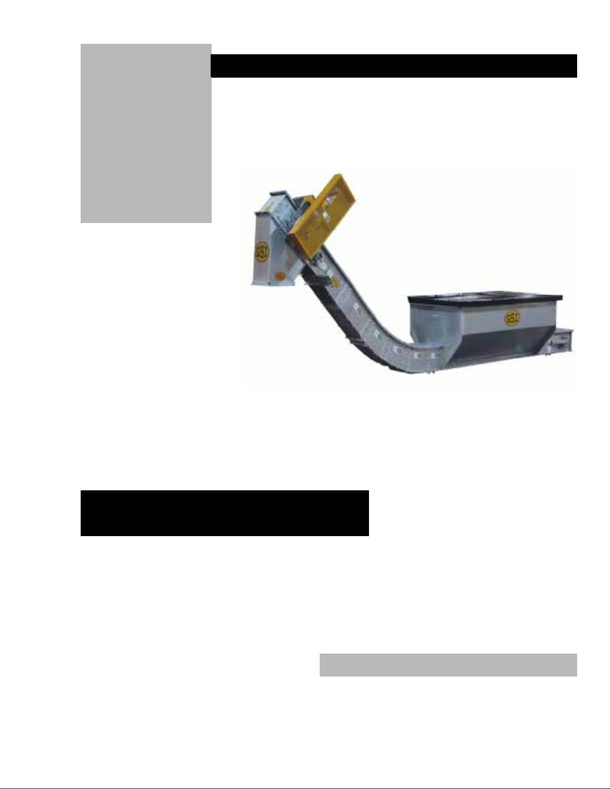
C hain C onveyor
Incline Chain Conv eyor
Series
Installation and Operation Manual
PNEG-1056
1
Page 2

SAFETY GUIDELINES
This manual contains information that is important for you, the owner/operator, to know and
understand. This information relates to protecting personal safety and preventing
equipment problems. It is the responsibility of the owner/operator to inform anyone
operating or working in the area of this equipment of these safety guidlines.To help you
recognize this information, we use the symbols that are defined below.
Please read the manual and pay attention to these sections. Failure to read this manual
and it’s safety instructions is a misuse of the equipment and may lead to serious injury or death.
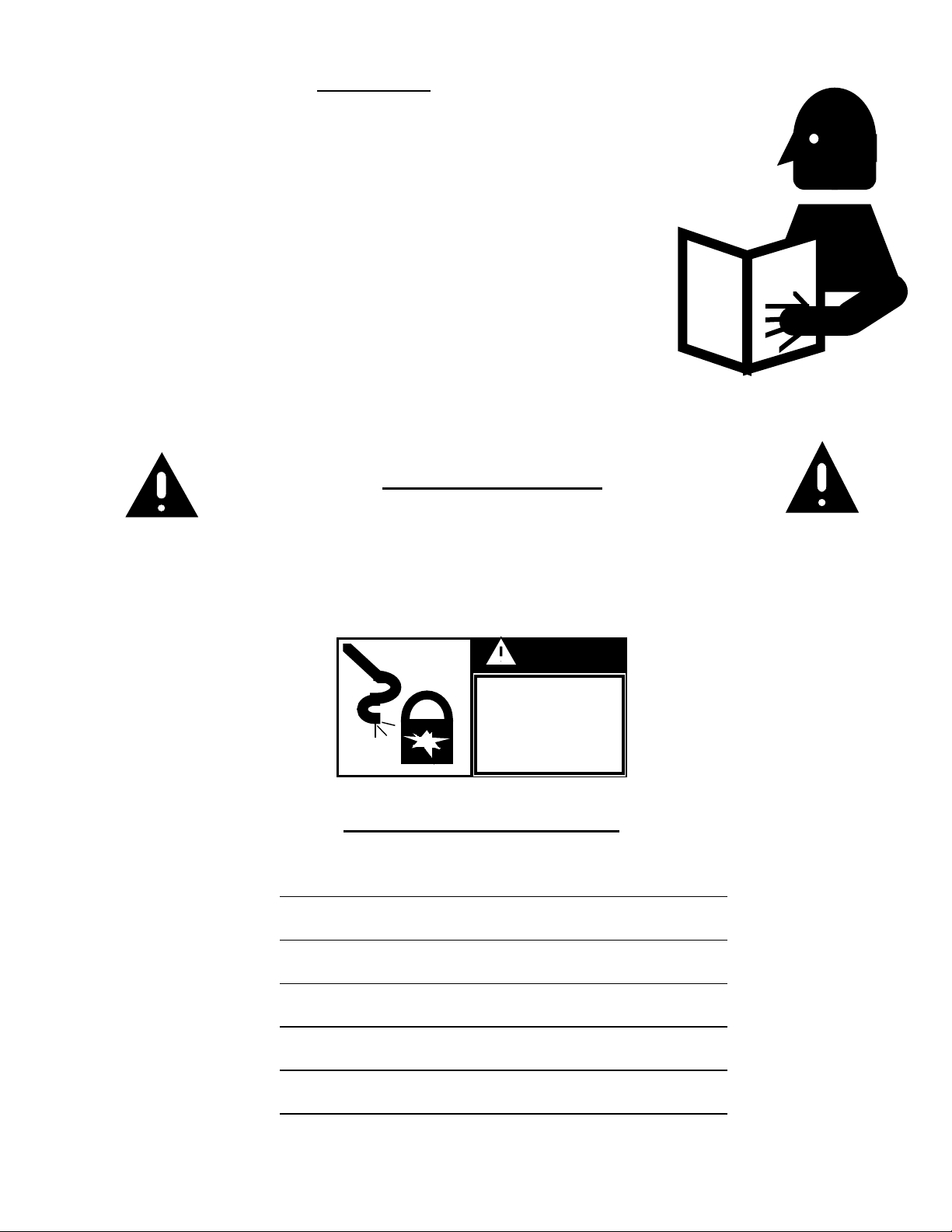
This is the safety alert symbol. It is used to alert you
to potential personal injury hazards. Obey all
safety messages that follow this symbol to avoid
possible injury or death.
DANGER indicates an imminently hazardous situation
which, if not avoided, will result in death or serious injury.
WARNING indicates a potentially hazardous situation
which, if not avoided, could result in death or serious injury.
CAUTION indicates a potentially hazardous situation which,
if not avoided, may result in minor or moderate injury.
CAUTION used without the safety alert symbol indicates a
potentially hazardous situation which, if not avoided, may
result in property damage.
NOTE indicates information about the equipment that you
should pay special attention to.
- 2 -
Page 3

TABLE OF CONTENTS
EQUIPMENT INFORMATION................................................................... 4
SAFETY DECAL LOCATIONS………………………………………….. 5
GENERAL PRECAUTIONS..................................................................….. 11
RECEIVING AND PRE-INSTALLATION................................................ 12
INSTALLATION………............................................................................... 13
CARE, MAINTENANCE, STORAGE......................................................... 21
OPTIONS...................................................................................................…. 25
TROUBLE SHOOTING………………………………………………….. 29
TRAINING SIGN OFF SHEET………………………………………….. 30
MAINTENANCE RECORD……………………………………………… 31
WARRANTY………………………………………………………………. 32
- 3 -
Page 4
Introduction
We encourage all personnel operating, installing, or maintaining this
equipment to thoroughly read this manual before proceeding. Successful
operation is our intention; however, if in fact you are in need of technical
advice or support, we encourage you to contact your local dealer/distributor
or contact the factory at any time during regular business hours at 217-226-
4421. Our commitment is to you the customer, and we encourage your input
and/or suggestions that would help better our product.
s
r’
o
t
ra
This manual covers general information on incline conveyor (straight and
bend incline configurations) installation. Due to the varying sizes of
equipment it would be very difficult to cover every aspect of installation. We
offer one method for erecting conveyors but many times the contractor’s
experience and techniques will work. Many times conditions and
surroundings do not allow certain practices during the erection of
equipment. We cannot be responsible for the erection of the conveyor
(unless so contracted to do so).
e
p
O
l
a
u
n
a
M
Safety Information
It is the responsibility of the buyer to make this manual available to the person
or persons involved with this equipment. Guards and safety labels have been installed prior to the
equipment leaving the manufacturing plant. These devices are not to be removed, altered, or defaced,
otherwise voiding any liability or responsibility of the manufacturer. Power lock out is very important prior
to installation, adjustment, and maintenance of the unit.
DANGER
Disconnect and
Lockout Electric
Power Before
Servicing U n it
Equipment Information
Model Number:
Serial Number:
Date Purchased:
Dealer/Distributor:
- 4 -
Page 5
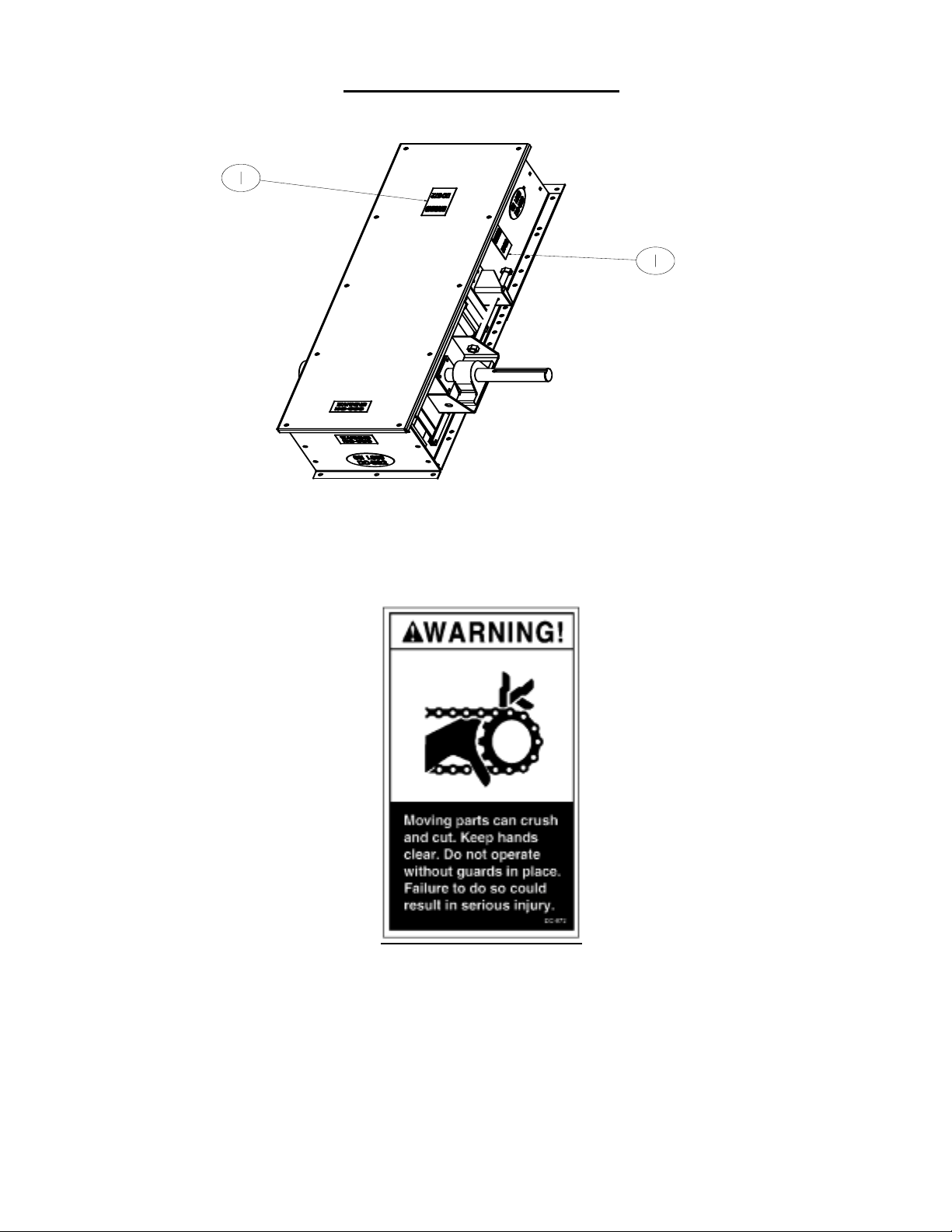
Head Section Decal Locations
1.
- 5 -
Page 6
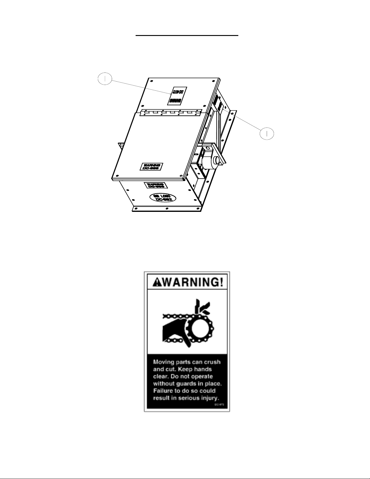
Tail Section Decal Locations
1.
- 6 -
Page 7
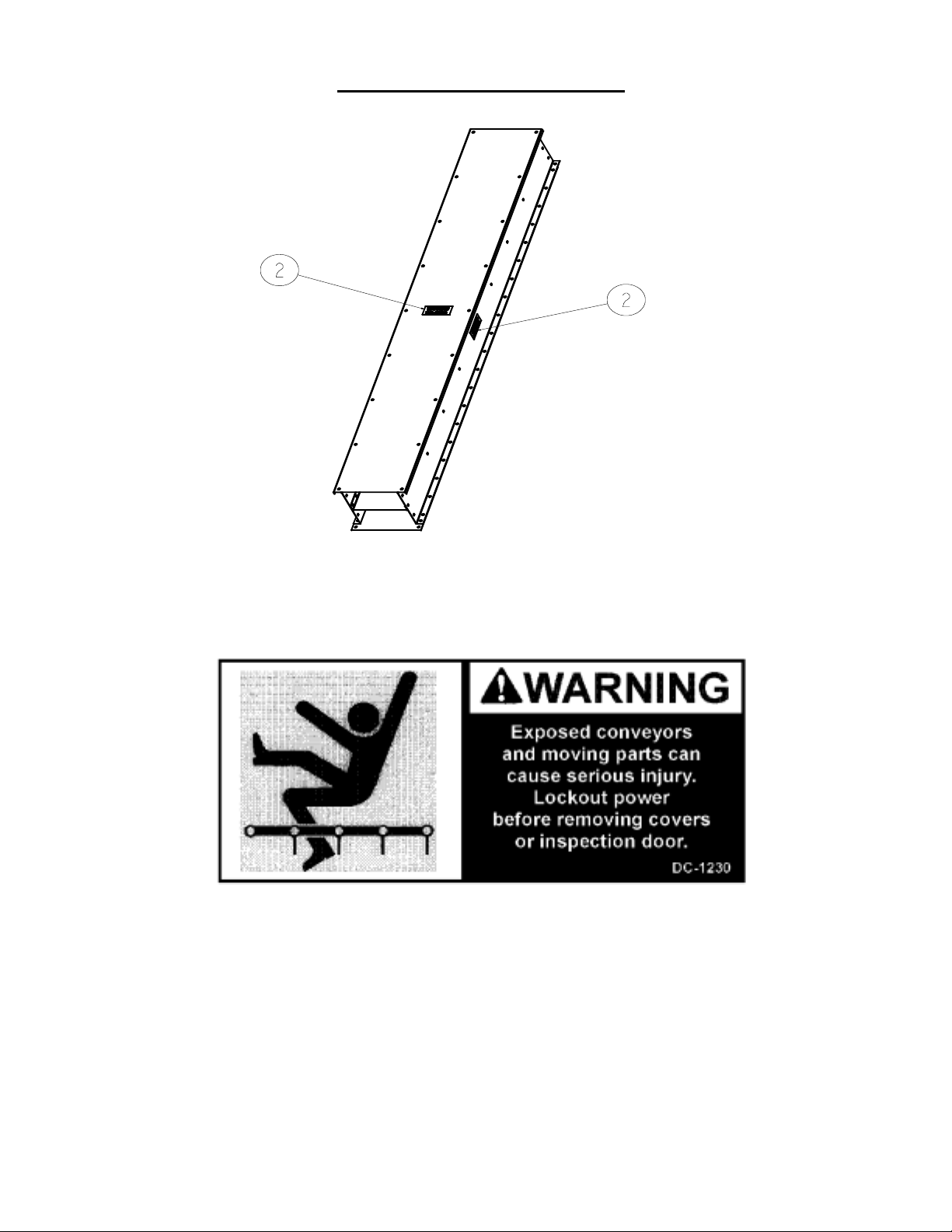
Trough Section Decal Location
2.
- 7 -
Page 8
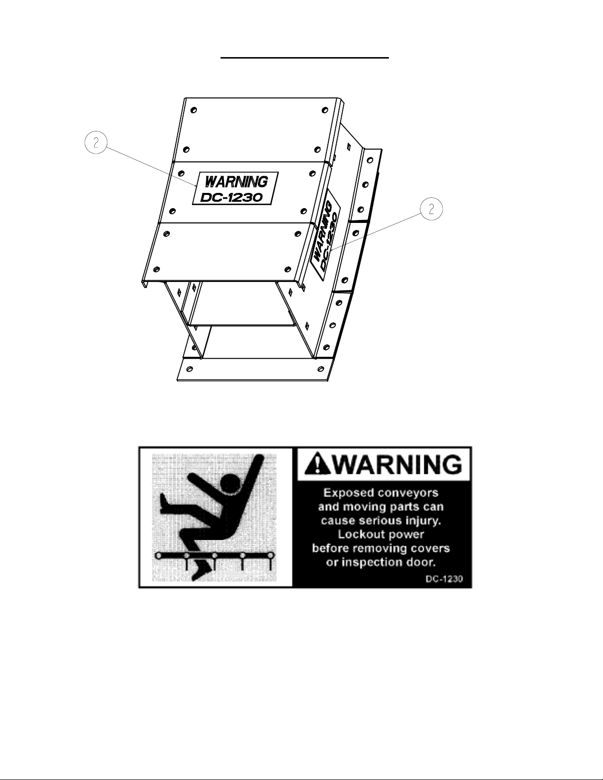
Bend Section Decal Location
2.
- 8 -
Page 9
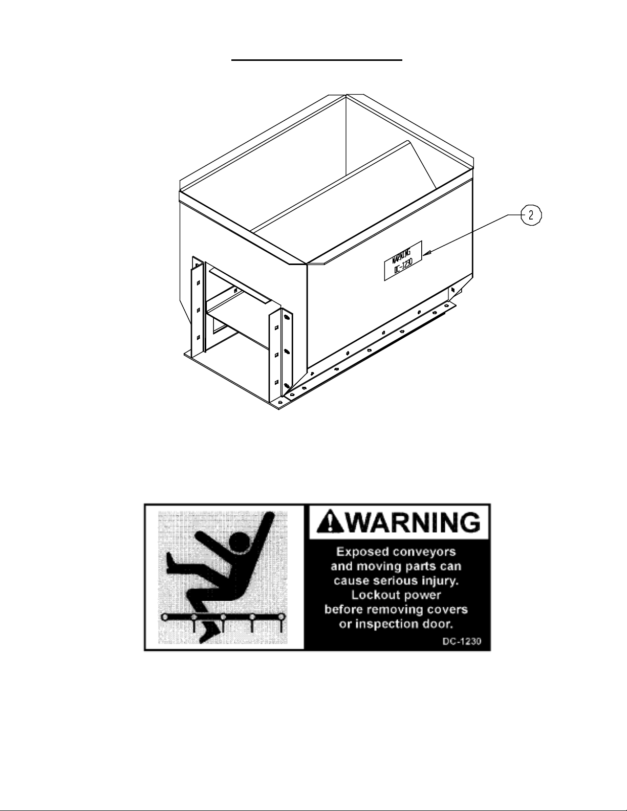
Bypass Inlet Decal Location
2.
- 9 -
Page 10
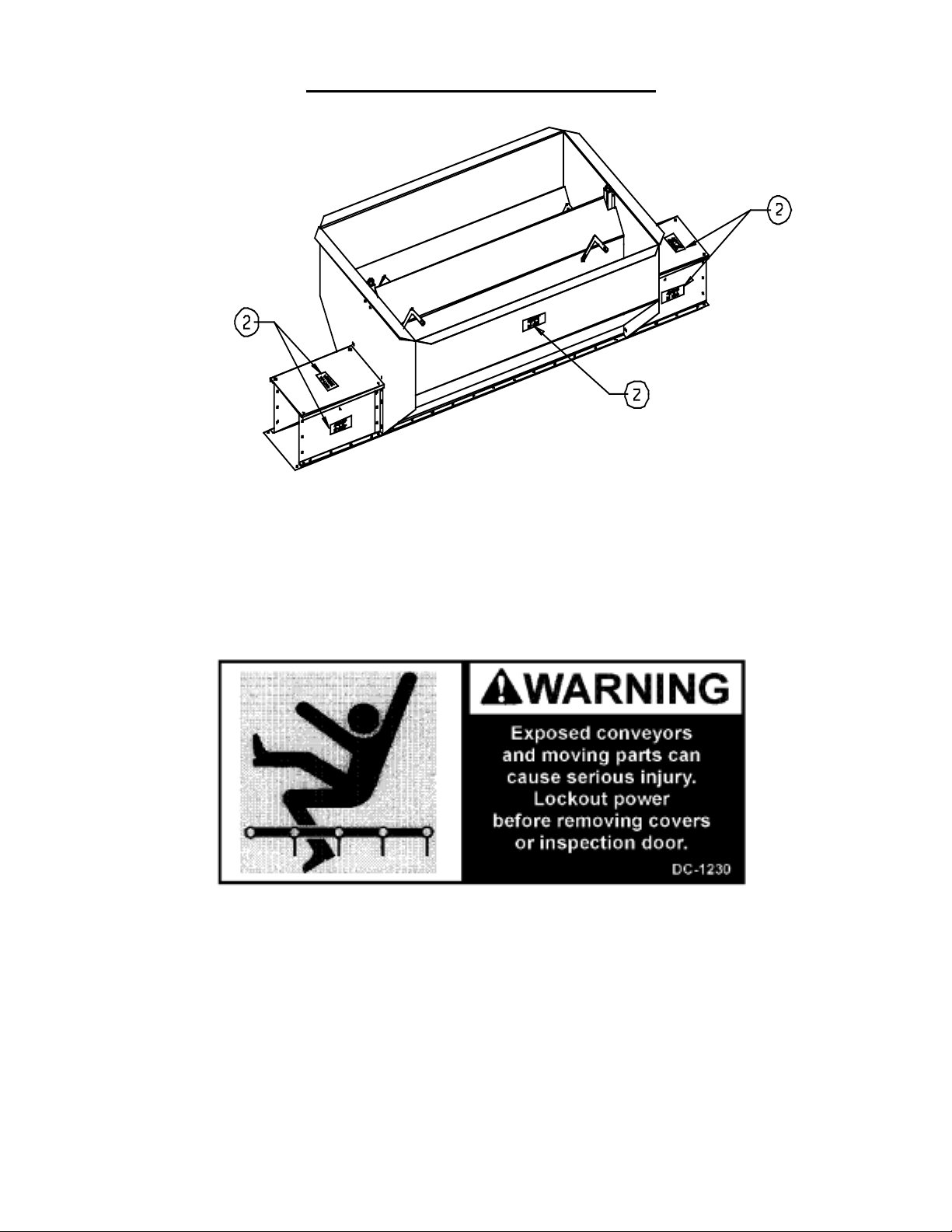
Bypass Dump Hopper Decal Location
2.
- 10 -
Page 11

CAUTION
1. Do not operate the unit before reading and understanding the
operator’s manual.
2. Keep all safety shields and devices in place.
3. Make certain everyone is clear of the equipment before operating or moving
the machine.
4. Keep hands, feet, and clothing away from moving parts.
5. Shut off and lock out all power to adjust, service, clean,
or unclog.
6. Keep off the equipment at all times.
7. Keep children, visitors, and all untrained personnel away
from machine while in operation.
8. Do not operate electric motor equipped units until motors are properly
grounded.
9. Disconnect power on electrical driven units before resetting motor overloads.
10. Do not repetitively stop and start the drive in order to free a plugged
condition. Jogging the drive in this type of condition can damage the conveyor
and/or drive components.
- 11 -
Page 12

SET-UP INSTRUCTIONS
This manual is provided by the company to aid in the assembly, operation, and maintenance of
its conveyors. Should a question arise concerning the assembly or operation of this unit not
covered by this manual, please contact the company at 217-226-4421 during regular business
hours and ask for assistance.
In this manual, right and left are determined by standing behind the unit and facing toward the
drive section (See figure below).
UNPACKING
Carefully inspect the shipment as soon as it is received. Verify that the quantity of parts and
packages corresponds to the quantity shown on the packing slip. Any discrepancies should be
clarified immediately. Please remember that any damage or missing parts must be noted on the
bill of lading at the time of delivery. Report any damage or shortages to the delivering carrier as
soon as possible. The company’s responsibility for damage to the equipment ends with the
acceptance by the delivering carrier. It is not the responsibility of the company to file claims for
damages with the appropriate carrier.
Save all paper work and documentation furnished with any of the chain conveyor
components.
- 12 -
Page 13

Installation
The following guidelines dealing with the installation of the Series I incline conveyors are
provided for your convenience. The company cannot be held responsible for the installation of
this unit.
Clearance
A clearance of at least the width of the conveyor is recommended on all sides of the unit. This
amount of clearance is not a necessity; less clearance maybe acceptable. However, serious
consideration must be given to methods of maintenance, removal and replacement of the
conveyor and/or its parts.
Support & Welding
No welding of any kind on or to the conveyor is recommended. Welding on or to the conveyor
may cause damage to both the conveyor and its electrical system. If welding is necessary, the
manufacturer prefers that the attachments or supports be welded to bottom splices. Should it be
necessary to fasten anything to the conveyor permanently, careful consideration should be given
to methods of maintenance, removal and replacement of the conveyor and/or its parts.
- 13 -
Page 14

Head Section
The head section of the conveyor is shipped pre-assembled from the factory. Each head
section has a tag with serial number. There are sub-assembly instructions in the care and
maintenance section of this manual.
Tail Section
The tail section of the conveyor is shipped pre-assembled from the factory. Each tail section has
a tag with serial number. There are sub-assembly instructions in the care and maintenance
section of this manual.
- 14 -
Page 15

Trough Assembly
Intermediate trough sections come both factory pre-assembled or unassembled. Your order
will serve as a reference to how your trough section should arrive.
Assembly sequence for trough sections unassembled:
Fasten trough bottom panel to each trough side panel using 3/8” hex head bolts and 3/8” whiz
nuts. Whiz nuts should be located on bottom side of conveyor. The trough bottom panel should
extend beyond trough side panels approximately two inches on one end and recessed
approximately two inches on the other end.
Fasten center pan, with flange up, using 3/8” carriage bolts through holes provided in trough
side panels. At the seams the carriage bolts below the center pan should be welded to the trough
side panels. Heads of carriage bolts should be inside the conveyor. For liner package assembly
check options portion of this manual.
Conveyor Assembly
Remove trough covers from trough sections to aid the conveyor assembly.
Position a head, tail or other intermediate trough section with holes in bottom flange of trough
sides aligned with holes in bottom panel of another section. Using a bottom splice, (4) 3/8” bolts
and (4) 3/8” whiz nuts fasten the two sections together. The bottom splice should cover the gap
between the two bottom panels, which is offset two inches from the gap in the trough sides.
Position trough splices over the gap between the end of the trough sections and fasten with 3/8”
carriage bolts and 3/8” whiz nuts.
Discharge
The standard conveyor is constructed with one discharge located at the drive end. Attach the
discharge transition to the bottom of the conveyor head using 3/8” bolts and 3/8” whiz nuts.
- 15 -
Page 16

Drive Package Assembly
Using hardware provided, attach motor mount angles to
motor mount adapter. There are only two motor mount
angles on reducers up to a 3 7/16” bore. For reducers with 3
15/16” bore and larger there are four motor mount angles.
Attach motor base to motor mount adapter using
all-thread rods (4) and nuts (16) provided in hardware
package. (Note orientation of motor base.)
Attach this assembly to the reducer, using the existing
bolts in the reducer. The angles should be mounted on the
same side as the input shaft.
Remove any rust, paint or imperfections from the drive
shaft. The drive shaft must be clean and shiny before
installing the reducer drive.
Slide the reducer bushing onto the shaft.
Mount the reducer onto the drive shaft and fasten in place
using the reducer bushing and cap screws provided. Do not
tighten the bushing cap screws until the end of the drive
shaft is protruding through reducer at least a 1/8”. Make
sure adequate space remains between the bearing and the
reducer bushing to allow removal of the bushing cap screws.
- 16 -
Page 17

Attach torque arm channel to bottom of conveyor. Some holes
may have to be field drilled in bottom panel to attach torque arm
channel. The position of the torque arm channel depends on the
incline of the head. When the head is on the incline desired the
reducer should still be vertical. The torque arm channel should be
placed so the torque arm from the reducer can reach when reducer
is in the vertical position.
Connect the adjustable torque arm from the reducer to the
torque arm channel. Make sure torque arm is mounted on the side
of reducer nearest to the torque arm channel. The torque arm
should be mounted parallel to the conveyor side.
Fasten the motor to the motor mount with hardware provided.
Connect the conveyor motor to a power source according to the
motor manufacturer’s instructions and recommendations. Due to
the hazards involved with electricity, it is recommended that an
electrician perform the motor wiring. A shut off switch should be
placed near the motor so that the system may easily be shut down
to help prevent accidents during maintenance.
Attach upper belt guard bracket and lower belt guard bracket to
reducer with hardware provided. The upper bracket should be
mounted to the upper holes in the motor mount adapter. The
lower bracket is two pieces. The two pieces should be mounted
together at slotted holes and then mounted to the reducer.
- 17 -
Page 18

Place the rear belt guard panel onto the reducer
drive shaft and the motor shaft. Attach to the upper
and lower brackets with hardware provided.
Remove any rust, paint or imperfections from the
motor shaft. Install the motor sheave and sheave
bushing on the motor shaft.
Remove any rust, paint or imperfections from the
reducer drive shaft. Install the reducer sheave
and sheave bushing on the reducer drive shaft
Align the reducer sheave and the motor sheave.
With both sheaves aligned tighten all hardware.
Place the drive belts provided on the sheaves.
Adjust the all-thread on motor base to tighten
according to the instructions provided with reducer.
Proper belt tension is 1/64”of deflection per one (1“)
inch of sheave centers on one side of the belt, centered
between sheaves. (See figure 1)
Position front belt guard cover into the rear belt
guard panel and attach using the clips mounted on belt
guard panel.
Check lubricant level in the reducer before operation.
Follow manufacturer recommendations for reducer
lubrication.
- 18 -
Page 19

Chain
All chain is shipped in approximate 10 foot lengths. The UHMW wiper flights should be in
front of the welded chain flights in the direction of chain travel (see diagram).
Adjust take-up screws to position the take-up sprocket as far from the end of the conveyor as
possible. Assemble all of the sections of chain using the connecting links provided with chain
assembly. With the assembled conveyor mounted in its permanent position, install the chain
assembly in the bottom of the conveyor and wrap chain around the sprocket at the head and tail
of the conveyor. Using a ratchet cable puller, pull the two ends of the chain together. Remove
the unneeded chain and fasten the two ends together using a connecting link furnished with the
chain assembly. Adjust take-up screws to tighten the chain.
81X Chain Assembly 4” Pitch Roller Chain Assembly
- 19 -
Page 20

Cover
Rope or silicone caulk should be used on all surfaces where the trough covers splices come in
contact with the trough covers. Bolt all of the trough cover panels in place using 3/8” bolts and
3/8” whiz nuts. Leave the end bolt holes open on each trough cover for the installation of the
cover splices. Install the cover splices over the gaps in the trough covers using 3/8” bolts and
3/8” whiz nuts.
Inlet Assembly
Inlets mounted too close to the tail chain sprockets will allow grain to come in contact with the
sprocket and chain pinch. This may cause excessive damage to any grain being conveyed. The
minimum distance from the tail splice joint to the nearest edge of the inlet assembly should be
equal to the inlet opening plus 2 inches (A + 2” in Figure 2).
The angle iron guard in the middle of the inlet assembly should be in position to divert flowing
grain from the chain links.
When the proper position for the inlet is determined, a full conveyor width opening should be
cut into the conveyor cover. Another opening should be cut in the center pan. The opening
should start at the edge of the inlet and extend a distance of twice the inlet opening, towards the
tail. The width of the opening should be determined by starting the opening a distance of 1 ¼”
from inside edge of conveyor. (See Figure 2)
Using the inlet assembly provided, drill 7/16” holes in the top flange of the conveyor trough
sides.
Fasten the inlet assembly in place using 3/8” bolts and 3/8” whiz nuts.
Use the same caulking material for the inlet assemblies that was used for the trough cover
panels.
Figure 2
- 20 -
Page 21

Care and Maintenance
The care and maintenance section is provided with the intention of helping to extend the useful
life of the unit. Like all equipment, the useful life of the conveyor is greatly reduced if not used
wisely and well maintained.
Before any maintenance is performed to the conveyor,
power must be shut off and locked out to prevent
accidental start up!
Check oil level in shaft mount reducer periodically. Fill to level as recommend by
Manufacturer.
Check all bearings and moving parts daily during use.
Follow bearing manufacturer recommendations.
Lubricate all greasable fittings two to three times during the use season. Use a good grade
lubricant. Do not over-lubricate.
The V-belt(s) should be periodically inspected for proper tension and wear. V-belts should be
replaced as necessary. If replacement or tension adjustment is required, refer to the Assembly
Section(s).
The drag chain and sprockets should be checked periodically for wear, damage, and proper
adjustment. Any broken or bent paddles should be replaced or straightened. Should adjustment
or replacement of the drag chain or sprockets be required, refer to the Assembly Section(s).
Storage
If the unit is to be inactive for an extended period, the following procedures are recommended.
Thoroughly clean the unit.
Loosen the drag chain tension. Doing so relieves the stress placed on the bearings and shafts of
the drive and tail sections.
Lubricate drag chains, shafts, and drive components with a good grade of light machine oil.
- 21 -
Page 22

Incline Conveyor Head Section Sub-assembly
Assembly sequence for incline head section sub-assembly.
Fasten head bottom panel to each head side panel using 3/8” hex head bolts and 3/8” whiz nuts.
Whiz nuts should be located on bottom side of conveyor. The head bottom panel should extend
beyond head side panels approximately two inches.
Mount divider with flange up using 3/8” carriage bolts and 3/8” whiz nuts through holes
provided in head side panels. Heads of carriage bolts should be inside the conveyor
Insert key into shaft. Slide sprocket onto the head shaft. DO NOT
this time. After final assembly of head section unit, the sprocket must be centered between the
side panels before tightened into place.
Place UHMW seal sandwich (white plastic rectangle with large slot) seal onto each end of
shaft/sprocket assembly. Insert each end of shaft/sprocket assembly into take-up bearing
weldment. Place UHMW seal (white plastic square with one large hole and four smaller holes)
onto each end of shaft/sprocket assembly. Mount seal over 5/16” studs with 5/16” whiz nuts.
Insert each end of shaft/sprocket assembly into properly sized pillow block bearing. Mount
pillow block bearings to take-up bearing weldment. DO NOT TIGHTEN setscrews at this
time.
TIGHTEN setscrews at
Slide above assembly into slot at end of head until take-up bearing weldment hits take-up stop.
Fasten false panel and false panel bracket to head side panels with 3/8” carriage bolts and 3/8”
whiz nuts. Attach end panel to side panels of head with 3/8” hex head bolts and 3/8” whiz nuts.
- 22 -
Page 23

Take-up rod should have one welded nut already in place. Place another nut on rod and insert
into take-up anchor. Place two nuts onto take-up rod and insert into take-up bearing weldment.
Finish by placing nut with pre-drilled hole on rod, place roll pin through nut and rod.
Attach discharge transition weldment to head side panels using 3/8”hex head bolts and 3/8”
whiz nuts. Then attach discharge transition splice plate between head bottom panel and
discharge transition. If a bottom liner is specified, a spacer between the head bottom panel and
the discharge transition splice is furnished, and should be properly positioned between these two
components before fasteners are inserted.
Center sprocket between head side panels and tighten all setscrews.
Place cover assembly on top of conveyor and fasten with 3/8” hex head bolts and 3/8” whiz
nuts.
Incline ConveyorTail Section Sub-Assembly
Assembly sequence for incline tail section sub-assembly.
Fasten tail bottom panel to each tail side panel using 3/8” hex head bolts and 3/8” whiz nuts.
Whiz nuts should be located on bottom side of conveyor. The tail bottom panel should be
recessed approximately two inches.
- 23 -
Page 24

Insert key into shaft. Slide sprocket onto the tail shaft. DO NOT TIGHTEN setscrews at this
time. After final assembly of tail section unit, the sprocket must be centered between the side
panels before tightened into place.
Place UHMW (white plastic square with large hole) seal onto each end of shaft/sprocket
assembly. Insert each end of shaft/sprocket assembly into properly sized pillow block bearing.
DO NOT TIGHTEN setscrews at this time.
Slide above assembly into slot at end of tail until pillow block bearings can be mounted onto
the bearing weldments with the bolt, flat washers, lock washers, and nuts provided in the
hardware bag.
Bolt seal retainer bracket and false panel in place using 5/16” hex head bolts and 5/16” whiz
nuts. Fasten false panel and false panel bracket to tail side panels with 3/8” carriage bolts and
3/8” whiz nuts. Position seal retainer angle inside seal retainer bracket and push towards tail
side panel to secure the tail shaft seal. Secure the seal retainer angle in place with 5/16” hex
head bolts and 5/16” whiz nuts. Attach end panel to side panels of tail with 3/8” hex head bolts
and 3/8” whiz nuts.
Center sprocket between tail panels and tighten all setscrews.
Place cover assembly on top of conveyor and fasten with 3/8” hex head bolts and 3/8” whiz
nuts.
- 24 -
Page 25

Options
The standard Series I incline conveyors have been designed to meet most conveyor operation
criteria. However, to better serve customer special applications, a number of options are
available for the conveyors. Descriptions of the options, their installation, care and maintenance
will be covered in this section.
WARNING! POWER MUST BE
SHUT OFF AND LOCKED OUT
BEFORE ANY OPTIONS ARE
INSTALLED.
Liner Packages
Bottom A.R. liners come standard with a galvanized cover sheet. The installation is the same
as the standard 8-gage bottom.
Shock Relay
Refer to installation instructions within the shock relay package.
Standard Bypass Inlets
Standard bypass inlets come pre-assembled from the factory. The inlets are a standard 28 in.
conveyor section. The hogback is stationary in standard bypass inlets. Standard bypass inlets
must be mounted horizontally. If not mounted horizontally, capacity will be reduced.
Standard Bypass Inlet
- 25 -
Page 26

Bypass Dump Hoppers
Bypass dump hoppers come pre-assembled from the factory. The bypass dump hoppers
replace a standard 10-ft. conveyor section. The hoppers can be 6-ft., 8-ft., and 10-ft. lengths.
The hogback is adjustable in the bypass dump hoppers. Bypass dump hoppers must be mounted
horizontally. If not mounted horizontally, capacity will be reduced.
6-ft. Bypass Dump Hopper
8-ft. Bypass Dump Hopper
10-ft. Bypass Dump Hopper
- 26 -
Page 27

Grate
Grates are shipped from factory in sections.
10’ Bypass Dump Hopper Grate
8’ Bypass Dump Hopper Grate
6’ Bypass Dump Hopper Grate
- 27 -
Page 28

10 Foot Adjustable Bypass Inlets
10 foot adjustable bypass inlets come pre-assembled from the factory. The 10 foot adjustable
bypass inlets are a standard 120 in. conveyor section. The hogback is stationary, with an
adjustable baffle at each side inlet to the bottom chamber of the conveyor. 10 foot adjustable
bypass inlets must be mounted horizontally. If not mounted horizontally, capacity will be
reduced.
10 Foot Adjustable Bypass Inlet
Grate
Grates are shipped from factory in sections.
10’ Adjustable Bypass Inlet Grate
- 28 -
Page 29

Trouble Shooting
Trouble Shooting Guide
Problem Cause Solution
Low Capacity Improper chain speed Check the shaft RPM
Improper feed Check the grain level at inlet
Plugging Check the discharges
Baffle or adjustable hogback Increase opening
setting too low
Noisy Operation Loose UHMW Paddles Check all bolts on chain
Bottom and/or Divider Check intermediate trough section
not aligned Joints and make flush
Worn drive components Check oil level and shaft seals
Belt misalignment; loose belts
Worn chain and/or sprockets Check chain sprockets and chain
Uneven UHMW Conveyor Misalignment Check the conveyor alignment
Paddle Wear Sprocket Slipped Check set screws on sprockets
Uneven sprocket wear Worn chain Replace chain
Improper alignment Check sprocket alignment
Contact your local contractor for added assistance.
- 29 -
Page 30

EMPLOYER / EMPLOYEE TRAINING SIGN OFF SHEET
The company is making every effort to warn, guard, and educate the consumer when using
the various kinds of equipment that we manufacture. The company has included this sign
off sheet for you and your staff to use in the training process on installation and operation
of the equipment described in this manual. Read the entire manual, sign off, and date on
chart below.
DATE EMPLOYEE SIGNATURE DATE EMPLOYEE SIGNATURE
- 30 -
Page 31

EQUIPMENT MAINTENANCE RECORD
DATE MAINTENANCE PERFORMED INITIAL
- 31 -
Page 32

WARRANTY
THE COMPANY AS THE MANUFACTURER WARRANTS ALL PRODUCTS MANUFACTURED BY THE
COMPANY TO BE FREE OF DEFECTS IN MATERIAL AND WORKMANSHIP UNDER NORMAL USAGE
AND CONDITIONS FOR A PERIOD OF TWELVE MONTHS AFTER RETAIL SALE TO THE ORIGINAL
END USER OF SUCH PRODUCTS. THE COMPANY’S ONLY OBLIGATION IS, AND PURCHASER’S
SOLE REMEDY SHALL BE FOR THE COMPANY, TO REPAIR OR REPLACE, AT IT’S OPTION AND
EXPENSE, PRODUCTS THAT, IN IT’S SOLE JUDGEMENT, CONTAIN A MATERIAL DEFECT DUE TO
MATERIALS OR WORMANSHIP. ALL DELIVERY AND SHIPMENT CHARGES TO AND FROM THE
COMPANY’S FACTORY WILL BE PURCHASER’S RESPONSIBILITY. EXPENSES INCURRED BY OR ON
BEHALF OF THE PURCHASER WITHOUT PRIOR WRITTEN AUTHORIZATION FROM AN AUTHORIZED
EMPLOYEE OF THE COMPANY SHALL BE THE SOLE RESPONSIBILITY OF THE PURCHASER.
EXCEPT FOR THE ABOVE STATED EXPRESS LIMITED WARRANTIES, THE COMAPANY MAKES NO
WARRANTY OF ANY KIND, EXPRESSED OR IMPLIED, INCLUDING WITHOUT LIMITATION,
WARRANTIES OF MERCHANTABILTY OR FITNESS FOR A PARTICULAR PURPOSE OR USE IN
CONNECTION WITH (I) PRODUCT MANUFACTURED OR SOLD BY THE COMPANY OR (ii) ANY
ADVICE, INSTRUCTION, RECOMMENDATION OR SUGGESTION PROVIDED BY AN AGENT,
REPRESENTATIVE OR EMPLOYEE OF THE COMPANY REGARDING OR RELATED TO THE
CONFIGURATION, INSTALLATION, LAYOUT, SUITABILITY FOR A PARTICULAR PURPOSE, OR
DESIGN OF SUCH PRODUCT OR PRODUCTS.
IN NO EVENT SHALL THE COMPANY BE LIABLE FOR ANY DIRECT, INDIRECT, INCIDENTAL OR
CONSEQUENTIAL DAMAGES, INCLUDING, WITHOUT LIMITATION, LOSS OF ANTICIPATED PROFITS
OR BENEFITS. PURCHASER’S SOLE AND EXCLUSIVE REMEDY SHALL BE LIMITED TO THAT
STATED ABOVE, WHICH SHALL NOT EXCEED THE AMOUNT PAID FOR THE PRODUCT PURCHASED.
THIS WARRANTY IS NOT TRANSFERABLE AND APPLIES ONLY TO THE ORIGINAL PURCHASER.
THE COMPANY SHALL HAVE NO OBLIGATION OR RESPONSIBILTY FOR ANY REPRESENTATIVE OR
WARRANTIES MADE BY OR ON BEHALF OF ANY DEALER, AGENT OR DISTRUBTOR OF THE
COMPANY.
THE COMPANY ASSUMES NO RESPONSIBILITY FOR FIELD MODIFICATIONS OR ERECTION
DEFECTS WHICH CREATE STRUCTURAL OR STORAGE QUALITY PROBLEMS. MODIFICATIONS TO
THE PRODUCT NOT SPECIFICALLY COVERED BY THE CONTENTS OF THIS MANUAL WILL NULLIFY
ANY PRODUCT WARRANTY THAT MIGHT HAVE BEEN OTHERWISE AVAILABLE.
THE FOREGOING WARRANTY SHALL NOT COVER PRODUCTS OR PARTS WHICH HAVE BEEN
DAMAGED BY NEGLIGENT USE, MISUSE, ALTERATION OR ACCIDENT. THIS WARRANTY COVERS
ONLY PRODUCTS MANUFACTURED BY THE COMPANY. THIS WARRANTY IS EXCLUSIVE AND IN
LIEU OF ALL OTHER WARRANTIES EXPRESS OR IMPLIED. THE COMAPANY RESERVES THE RIGHT
TO MAKE DESIGN OR SPECIFICATION CHANGES AT ANY TIME.
PRIOR TO INSTALLATION, PURCHASER HAS THE REPONSIBILITY TO RESEARCH AND COMPLY
WITH ALL FEDERAL STATE AND LOCAL CODES WHICH MAY APPPLY TO THE LOCATION AND
INSTALLATION.
- 32 -
Page 33

T H E G S I G R O U P
1004 East Illinois Street
Assumption, Il 52510-0020
May-01
- 33 -
 Loading...