

Page 1
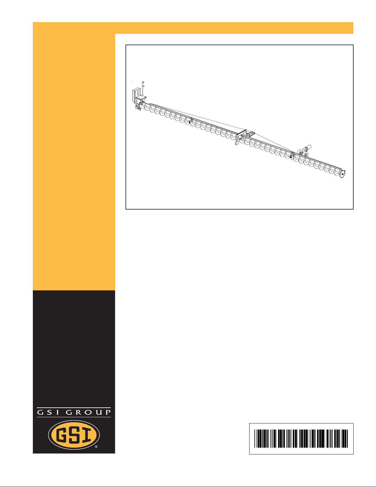
12" & 14" Commercial Bin
Sweep Auger
Assembly & Operation Manual
PNEG-1050
Date: 04-24-2007
PNEG-1050
Page 2

DO NOT STORE SWEEPS IN THE BIN!
Sweeps are NOT designed to remain in a bin during
filling, storage, or bottom (gravity) unloading. A sweep
left in a bin during these operations may be serverly
damaged. The GSI Group, Inc. will not be responsible for
such damages.
The following action may reduce damages to a sweep
remaining in a bin: Lifting the sweep off the center pivot,
positioning it parallel to the intermediate wells (along
side of - not on top of) and fully supporting the sweep to
the bin floor. However, even with this procedure, The
GSI group, Inc. will not be responsible for any damges to
the sweep.
2 12" & 14" Commercial Bin Sweep Augers PNEG-1050
Page 3

Table of Contents
TABLE OF CONTENTS
Safety ......................................................................................................... 4
General Information ..................................................................................... 12
Decals ........................................................................................................ 13
Assembly Section
Chain Reducer Drive ............................................................................. 14
Flight & Shield Assembly ....................................................................... 19
Sweep Carrier & T russ Assembly........................................................... 24
Sweep Flight Back Shield...................................................................... 25
End Wheel Assembly............................................................................. 26
Sweep Tractor ....................................................................................... 27
Installation Section
Procedures for Installing Into Bin & Unloading........................................ 30
Final Cleanout ....................................................................................... 33
Power Source ............................................................................................. 34
Lubrication.................................................................................................. 35
Trouble Shooting ......................................................................................... 35
Part Lists .................................................................................................... 36
Personnel operating or working around this equipment should read this
manual. This manual must be delivered with equipment to its owner.
Failure to read this manual and its safety instructions is a misuse of the
equipment. Any misuse of the equipment may void the warranty.
12" & 14" Commercial Bin Sweep Augers PNEG-1050
3
Page 4
Safety
SAFETY GUIDELINES
This manual contains information that is important for you, the owner/operator , to know and
understand. This information relates to protecting personal safety and preventing
equipment problems. It is the responsibility of the owner/operator to inform anyone
operating or working in the area of this equipment of these safety guidelines. T o help you
recognize this information, we use the symbols that are defined below.
Please read the manual and pay attention to these sections. Failure to read this manual
and it’s safety instructions is a misuse of the equipment and may lead to serious injury or death.
This is the safety alert symbol. It is used to alert you
to potential personal injury hazards. Obey all
safety messages that follow this symbol to avoid possible injury
or death.
DANGER indicates an imminently hazardous situation which, if not
avoided, will result in death or serious injury .
WARNING indicates a potentially hazardous situation which, if not
avoided, could result in death or serious injury .
CAUTION indicates a potentially hazardous situation which, if not
avoided, may result in minor or moderate injury .
CAUTION used without the safety alert symbol indicates a potentially
hazardous situation which, if not avoided, may result in property
damage.
NOTE indicates information about the equipment that you should pay
special attention to.
4 12" & 14" Commercial Bin Sweep Augers PNEG-1050
Page 5
FOLLOW SAFETY INSTRUCTIONS
Carefully read all safety messages in this manual
and safety signs on your equipment. Keep signs
in good condition. Replace missing or damaged
safety signs. Be sure new equipment components and repair parts include the current safety
signs. Replacement safety signs are available
from the manufacturer.
Learn how to operate the machine and how to
use controls properly . Do not let anyone operate
without instruction.
Keep your machinery in proper working condition. Unauthorized modifications to the machine
may impair the function and/or safety and affect
machine life.
Safety
If you do not understand any part of this manual
and need assistance, contact your dealer.
PRACTICE SAFE MAINTENANCE
Understand service procedures before doing
work. Keep area clean and dry.
Never lubricate, service, or adjust machine while
it is in operation. Keep hands, feet, and clothing
from rotating belt and idlers.
Keep all parts in good condition and properly
installed. Fix damage immediately. Replace
worn or broken parts. Remove any build up
grease, oil, or debris.
12" & 14" Commercial Bin Sweep Augers PNEG-1050
5
Page 6
Safety
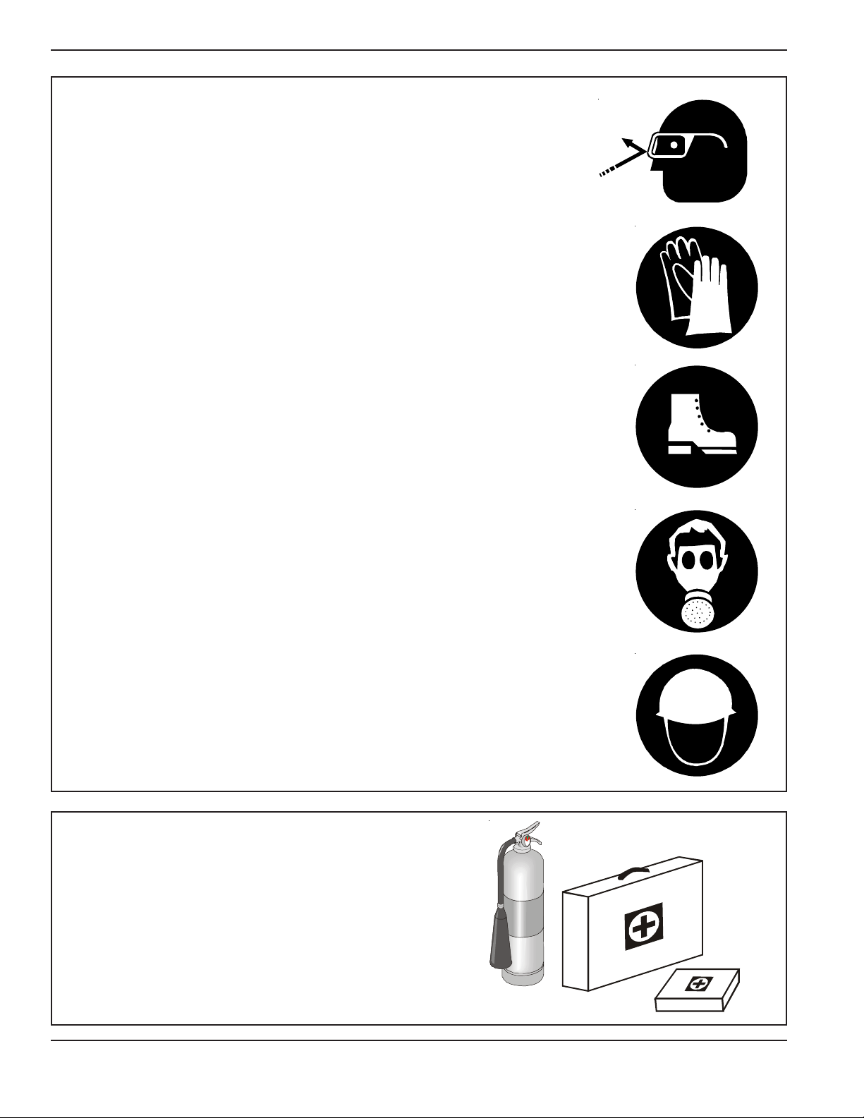
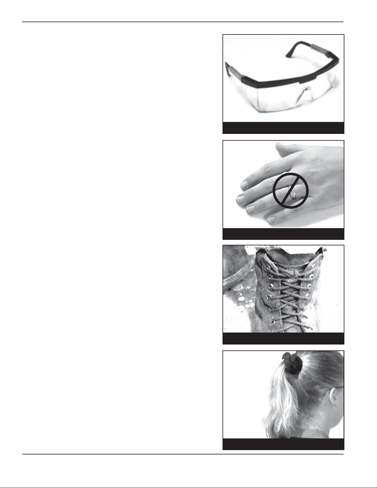
WEAR PROTECTIVE CLOTHING
Wear close fitting clothing and safety equipment
appropriate to the job.
Safety glasses should be worn at all times to
protect eyes from debris.
Wear gloves to protect your hands from sharp
edges on plastic or steel parts.
A respirator may be needed to help prevent
breathing potentially toxic fumes and dust.
Wear hard hat and steel toe boots to help
protect your head and toes from falling debris.
Eye Protection
Gloves
Steel Toe
Boots
PREPARE FOR EMERGENCIES
Be prepared if fire starts.
Keep a first aid kit and fire extinguisher handy .
Keep emergency numbers for doctors, ambu-
lance service, hospital, and fire department near
your telephone.
Respirator
Hard Hat
6 12" & 14" Commercial Bin Sweep Augers PNEG-1050
Page 7

SAFETY GUIDELINES
1. General Safety Guidelines
A. DO NOT make any alterations to the equipment. Such alterations may produce a very dangerous situation,
where SERIOUS INJURY or DEATH may occur .
B. This equipment shall be installed in accordance with any regulations or installation codes that are required by
law. Authorities having jurisdiction should be consulted before inst allations are made.
C. Untrained operators subject themselves and others to SERIOUS INJURY or DEA TH. NEVER allow untrained
personnel to operate this equipment.
D. Keep children and other unqualified personnel out of the working area at ALL times.
E. NEVER start equipment until ALL persons are clear of the work area.
Safety
F. Be sure ALL operators are adequately rested and prepared to perform ALL functions of operating this equipment.
G . Keep hair, loose clothing, and shoestrings away from rotating and moving part s. NEVER wear loose fitting clothing
when working around augers.
H. NEVER allow any person intoxicated or under the influence of alcohol or drugs to operate the equipment.
I. NEVER allow anyone inside a bin, truck, or wagon which is being unloaded by an auger or conveyor. Flowing
grain can trap and suffocate in seconds.
J. Make sure someone is nearby who is aware of the proper shutdown sequence in the event of an accident or
emergency .
K. NEVER work alone.
L. ALWAYS think before acting. NEVER act impulsively around the equipment.
M. Make sure ALL equipment is locked in position before operating.
N. Keep hands and feet away from the auger intake and other moving parts.
O. NEVER attempt to assist machinery operation or to remove trash from equipment while in operation.
P . Use ample overhead lighting after sunset to light the work area.
Q. ALWAYS lockout ALL power to the equipment when finished unloading.
R. Keep area around intake free of obstacles such as electrical cords, blocks, etc. that might trip workers.
12" & 14" Commercial Bin Sweep Augers PNEG-1050
7
Page 8
Safety
2. Personal Protective Equipment
A. The proper personal protective equipment should be
worn at ALL times by anyone in the work area.
B. ALWA YS wear safety glasses when in the work area.
C. The operator should NEVER wear jewelry.
2-B
2-C
D. Loose clothing should not be worn. Any clothing that
becomes loosened should be tucked in tightly .
E. Loose or dangling shoe strings should be tucked in.
F. Long hair should be tied up and/or back.
8 12" & 14" Commercial Bin Sweep Augers PNEG-1050
2-D, E
2-F
Page 9

3. In an Emergency, Shutdown the Power Source.
4. Hazards
A. Keep clear of all augers. DO NOT ENTER the bin!
B. If you must enter this bin:
1. Shut off and lock out all power .
2. Use safety harness and safety line.
3. Station another person out side the bin.
4. A void the center of the bin.
5. Wear proper breathing equipment or respirator.
C. Failure to heed these warnings will result in serious injury or death.
D. Be aware of Pinch Points. A Pinch Point is a narrow area between two surfaces that is likely to trap
or catch objects and so is a potential safety hazard.
E. Components of this equipment have sharp edges which can scrape and/or cut an operator.
F. A moving auger can sever appendages possibly resulting in death.
5. Shields and Guards
Safety
A. ALWAYS keep ALL shields and guards in place during operation.
We will replace any missing shields or guards free of charge!
See (page vi) for more information on our Safety First program.
6. Operator Qualifications
A. The User/Operator must be competent and experienced to operate auger equipment. Anyone who works
with or around augers must have good common sense in order to be qualified. These persons must also
know and meet all other qualifications, such as:
1. Any person who has not read and/or does not understand all operation and safety procedures is not
qualified to operate any auger systems.
2. Certain regulations apply to personnel operating power machinery. Personnel under the age of 18
years may not operate power machinery , including augers. It is your responsibility , as owner and/or
supervisor, to know what these regulations are in your area or situation.
3. Unqualified or incompetent persons are to remain out of the work area.
4. O.S.H.A. (Occupational Safety & Health Administration) regulations state: "At the time of initial assignment and at least annually thereafter , the employer shall instruct every employee in the safe operation
and servicing of all equipment with which the employee is, or will be involved." (Federal Occupational
Safety & Health Standards for Agriculture. Subpart D, Section 19287.57 (a) (6).
12" & 14" Commercial Bin Sweep Augers PNEG-1050
9
Page 10

Safety
6. Operator Qualifications (cont.)
B. As a requirement of OSHA, it is necessary for the employer to train the employee in the safe operating and
safety procedures for this auger . We included this sign-off sheet for your convenience and personal record
keeping. All unqualified persons are to st ay out of the work area at all times. It is strongly recommended
that another qualified person who knows the shutdown procedure is in the area in the event of an emergency .
A person who has not read this manual and understands all operating and safety instructions is not qualified
to operate the machine.
DATE EMPLOYER'S SIGNATURE EMPLOYEE'S SIGNATURE
1
2
3
4
5
6
7
8
9
10
11
12
13
14
15
16
17
18
19
20
21
22
23
24
25
10 12" & 14" Commercial Bin Sweep Augers PNEG-1050
Page 11
Safety
Our equipment is built to provide
many years of dependable service to
our customers through durable
craftsmanship.
One of the most important aspects of our engineering is SAFETY 1
st
design throughout all
product lines. At our company - safety is NO
ACCIDENT!
That is why we have implemented a SAFETY 1
program. Should you ever need guards,
shields, safety decals or owner/operator manuals, simply contact us or your local dealer , and
we will supply you with them FREE OF
CHARGE!
While it is our main goal for our
company to be a world leader in manufacturing,
it is always our first priority to keep our customers safe.
We replace missing guards and shields
FREE OF CHARGE!
st
If you need any of the above listed safety items or have any safety questions, please contact
the manufacturer or your local dealer.
12" & 14" Commercial Bin Sweep Augers PNEG-1050
11
Page 12

Safety
1. General Information
A. We reserve the right to improve our product whenever possible and practical to do so. We reserve the right to
change, improve, and modify products at any time without obligation to make changes, improvements, and
modifications on equipment sold previously.
B. The Commercial Bin Sweep Augers have been designed and manufactured to give years of dependable service.
The care and maintenance of this machine will affect the satisfaction and service obtained. By observing the
instructions and suggestions we have recommended, the owner should receive competent service for many
years. If additional information or assistance should be required, please contact the factory or your local dealer .
C.
Receiving Merchandise and Filing Claims
1. When receiving merchandise, it is important to check both the quantity of parts and their descriptions
with the packing list enclosed within each package. All claims for freight damage or short age must be
made by the consignee within ten (10) days from the date of the occurrence of freight damage. The
consignee should accept the shipment after noting the damage or loss.
For Claims Contact:
The GSI Group Inc.
1004 East Illinois Street
Assumption, IL 62510
Tele: (217) 226-4421
Fax: (217) 226-4420
12 12" & 14" Commercial Bin Sweep Augers PNEG-1050
Page 13
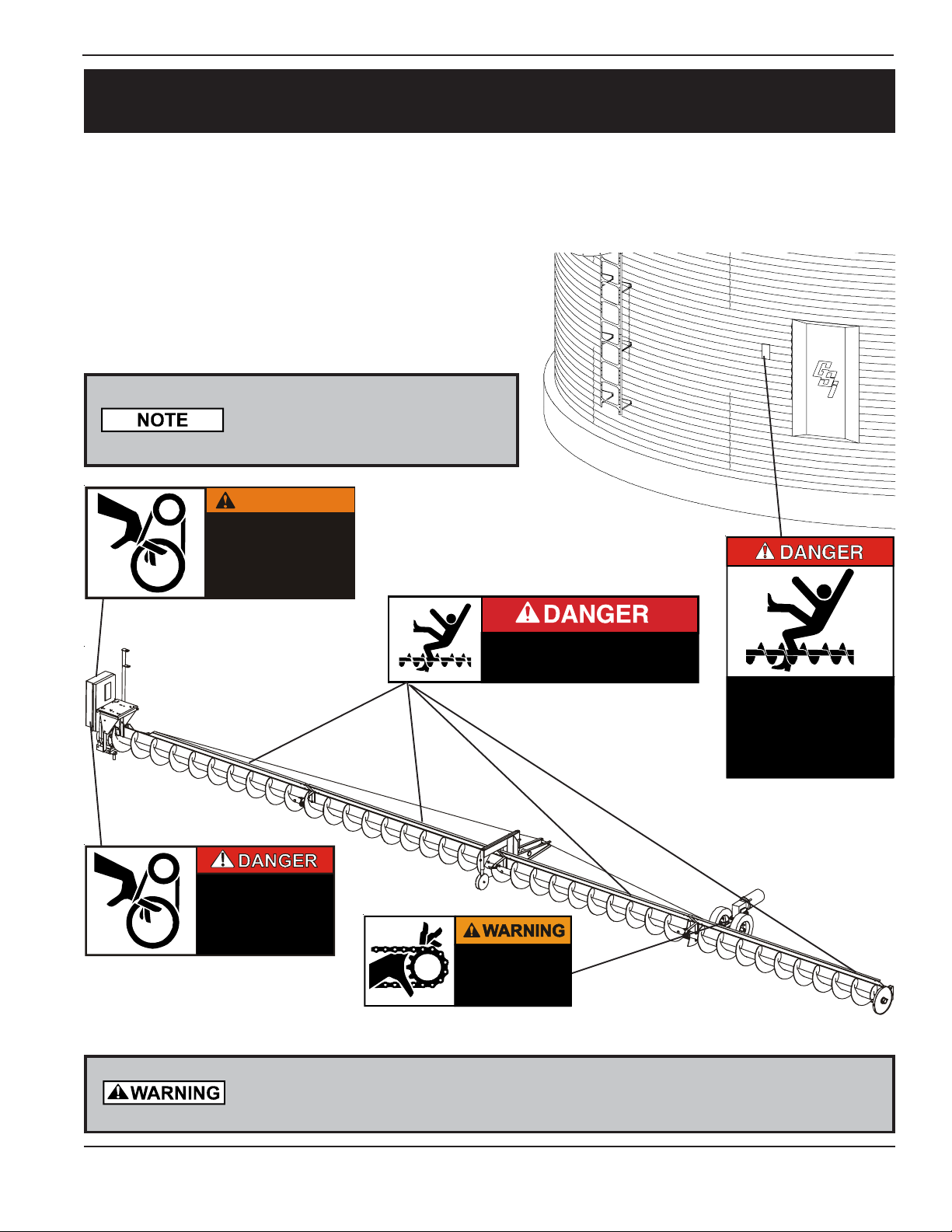
Decal
W
SAFETY DECALS
Check components shown below to insure that the safety decals are in place and in good condition. If a decal cannot be
easily read for any reason or has been painted over , replace it immediately . Contact your dealer or the manufacturer to
order a replacement decal free of charge.
DANGER Sign No. DC-1395 was supplied with your bin unloading equipment. This safety sign should be applied
to the side of the bin near the bin opening, so it will be viewed
by people entering into the bin storage building.
Do not cover any safety signs or any other signs that are
already there.
Please remember, safety signs
provide important safety information
for people working near bin unloading equipment that is in operation.
SHEAR POINT
Keep hands clear of moving
parts. Do not operate with
guard removed. Disconnect
and lockout power before
servicing.
Located on Outside of Belt Guard
DC-995
SHEAR POINT
Keep hands clear of moving
parts. Do not operate with
guard removed. Disconnect
and lockout power before
servicing.
Located Inside Belt Guard
DC-994
ARNING
DC-995
DC-994
KEEP OUT OF BIN WHILE SWEEP IS IN OPERATION
RAPIDLY TRAVELING SWEEP AUGER
FAILURE TO HEED WILL RESULT IN
SERIOUS INJURY OR DEATH
Located on Shield
DC-1384
SHEAR POINT
Moving parts can
crush and cut. Keep
hands clear of
sprocket and chain.
DC-13 86
Located on Tractor Drive Chain Guards
DC-1386
DC-1384
ROTATING FLIGHTING!
THIS BIN IS EQUIPPED WITH GRAIN AUGERS
WHICH CAN KILL OR DISMEMBER.
KEEP CLEAR OF ALL AUGERS AND NEVER ENTER
THIS BIN UNLESS ALL POWER IS
DISCONNECTED AND LOCKED OUT.
FAILURE TO DO SO WILL RESULT IN
SERIOUS INJURY OR DEATH!
DC-1395
Located Outside Bin Door
DC-1395
If the Safety Sign cannot be easily read for any reason or has been painted over,
replace it immediately. Additional Safety Signs may be obtained free of charge from
your dealer , distributor, or ordered from the factory .
12" & 14" Commercial Bin Sweep Augers PNEG-1050
13
Page 14
Assembly
1. CHAIN REDUCER DRIVE (For 36' thru 78' Diameter Bins)
A. Motor Mount Assembly Instructions’
(See Fig. 2 on page 15.)
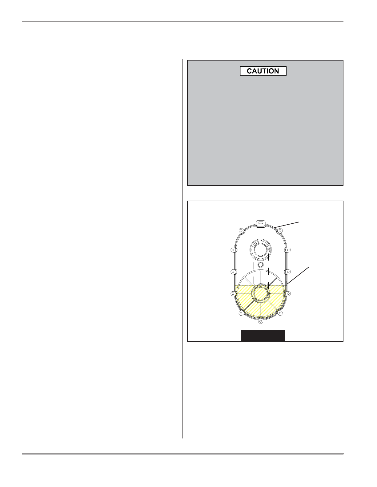
1. First, fill the chain reducer drive with oil by removing
the vented fill plug and pouring 48 oz. of oil into drive.
Oil level can be checked by removing the check plug.
Oil should not be over the check plug. (See Fig. 1)
2. Install Pivot Bracket (1) to bottom of motor mount
frame (2) using a 3/4" x 1 1" long (grade 5) hex head
capscrew and nylon locknut.
3. Attach the electric cord support stand (3) and one side
of the motor mount support plate (4) to the motor
mount frame (2) using two 1/2" x 1-1/2" long (grade 5)
hex head capscrews with lock washers and hex nuts.
Attach the other side of the motor mount support plate
(4) to the motor mount frame (2) using two 1/2" x
1-1/4" long capscrews with lockwashers and nuts.
4. Mount the chain reducer drive (6) to the mounting ring
on the motor mount frame (2) with four 3/8" x 1" long
(grade 5) hex head capscrews and nylon locknuts.
5. Screw the 3/4" threaded adjusting rod (7) down through
the nut welded to the top of the motor mount support
plate (4). Leave the adjusting rod (7) an inch or two
above the top surface of the motor mount support
plate (4). The adjusting rod will be adjusted later after
the drive belts are installed.
Oil must be added before assembly. The chain
reducer is shipped without oil.
Do NOT add more oil than recommended. Additional oil may damage the seals or be forced out
through the vented fill plug.
For lubrication in normal operating temperature
between 40° F to 120° F, we recommend the use
of non foaming, multi purpose gear oil, SAE 90
weight. For temperatures below 40° F, use a SAE
80 weight oil. Use grade commercially available
for automotive differentials. Extra pressure
additives may be of value in severe applications.
Enclosed Drive
Fill Plug
Check Plug
6. Thread a 3/4" hex nut onto the bottom end of the
adjusting rod (7) underneath the motor mount support
plate (4). This nut is for locking the adjusting rod in
place after adjusting it to the required position to
tighten the drive belts. DO NOT tighten this nut
against the motor mount support plate until the belts
have been installed and tightened.
7. Align the pivot holes (10) of the motor mount plate (4)
with those in the motor mount support plate (4) and
slide the pivot rod (9) through the holes. Insert a 3/16"
cotter pin into the holes in each end of the pivot rod (9)
to keep it in place.
14 12" & 14" Commercial Bin Sweep Augers PNEG-1050
FIG . 1
Page 15

1. CHAIN REDUCER DRIVE (cont.)
Assembly
(7) Adjusting Rod
(4) Motor Mount Support Plate
1/2" x 1-1/4" HHCS,
Lockwashers, and Nuts
(8) Motor Mount Plate
(10) Pivot Holes
(3) Electrical Cord
Support Sta nd
(9) Pivot Rod
1/2" x 1-1/2" HHCS
with Lock Washers
and Nut
(6) Chain Reducer Drive
3/8" x 1" HHCS Bolt
3/4" x 11" HHCS with
Locknut
(5) Shield Mount Plate
(2) Motor Mount Frame
(1) Pivot Bracket
1" Flat Washers
Pivot Tube in Center of Bin
FIG . 2
12" & 14" Commercial Bin Sweep Augers PNEG-1050
15
Page 16

Assembly
1. CHAIN REDUCER DRIVE (cont.) (Refer to Fig. 3.)
8. Slide the mounting ring of the belt guard (10) over the
mounting ring of the chain reducer drive (15).
9. Fasten the bottom of the belt guard (10) to the motor
mount frame (2) using two 3/8" x 1- 1/4" long (grade 5)
hex head capscrews, eight 1/16" thick flat washers
and two nylon locknuts. Position the flat washers
between the inside of the motor mount frame (2) and
the outside of the belt guard (10).
10.Use two 1/4" x 5" long hex head capscrews, belt guard
spacer tubes (1 1) and nylon locknuts to connect the
upper portion of the belt guard (10) to the motor mount
frame (2).
1 1 . Install electric motor on the motor mount plate (8).
(NOTE: The motor and motor mounting hardware are
not furnished.) (See Fig. 4 on page 17 for motor size
and bolt hole locations.)
FIG . 3
(8) Motor Mount
Plate
12.Install motor pulley on motor shaft and secure with
drive key . (NOTE: Motor pulley and drive key are not
furnished.) (See page 34 for pulley size.)
13. Slide 12" O.D. pulley (12) onto the input shaft of the
chain reducer (6). Using 1/4" square key (13) and
setscrew to secure pulley in place. Align motor pulley
with 12" O.D. pulley .
14. Install drive belts (14) on pulleys and tighten. Using a
wrench, turn the adjusting rod (7) ( installed in S tep 5
on page 14) so that it pushes against the bottom of
the motor mount plate (8). When the belts are tight,
screw the hex nut on the bottom side of the adjusting
rod tightly up against the nut welded to the bottom of
the motor mount support plate.
15. Bolt the belt guard door (10) closed with two 3/8" x
3/4" long (grade 5) hex head capscrews and nylon
locknuts.
(15) Chain
Reducer
Drive
(2)Motor
Mount
Frame
3/8" x 1-1/4" HHCS
3/8" x 1" HHCS &
Nylon Locknuts
(6) Input Shaft
(1 1) Belt Guard Spacer Tubes
(10) Belt Guard
1/16" Flat Washers
3/8" x 3/4" HHCS & Nylon Locknut
1/4" x 5" HHCS & Nylock Nut
(12) 12" O.D. Driven Pulley
(14) Drive Belt
(13) Square Key
16 12" & 14" Commercial Bin Sweep Augers PNEG-1050
Page 17

1. CHAIN REDUCER DRIVE (Cont.)
B. Motor Mount Hole Locations
Use the charts & illustration below to determine the location of the holes
where you need to install your motor .
Assembly
BIN DIA.
36' - 39' 7 -1/2 213T 3/8" * * * *
40' - 49' 10 215T 3/8" * * * *
BIN DIA.
54' - 78' 15 254T 1/2" ****
80' - 105' 20 256T 1/2" ****
113' - 120' 25 284T 1/2" * * * *
MOTOR
SIZE HP
MOTOR
SIZE HP
MOTOR
FRAME
SIZE
MOTOR
FRAME
SIZE
BOLT DIA.
REQUIRED
BOLT DIA.
REQUIRED
B10
B3
A5
MO UNT IN HOLES
MARKED (*)
A1 A2 A3 A4 A5 A6
MOUNT IN HOLES MARKED (*)
B1 B2 B3 B4 B5 B6 B7 B8 B9 B10 B11
B7
B9
B1
B5
A1
12" & 14" Commercial Bin Sweep Augers PNEG-1050
A3
Fig. 4
A2
B6
B2
A6
A4
B4
B11
B8
17
Page 18

Assembly
2. ELECTRICAL CORD SUPPORT STAND (Refer to Fig. 5.)
1. Fasten electrical cord support stand (1) to the side of
the motor mount support (2) with two 1/2" x 1-1/2" hex
head capscrews, flat washers, and locknuts.
2. Install electrical cord clamp (3) into plate (4) on
support stand. Secure in place with the jam nut (7)
provided with the clamp.
Route Cord Through
Ring on Top of
Support St and
(4) Plate
(7) Jam Nut for
(8) Motor
Cord Clamp
3. Route the electrical cord (5) from the electrical junction
box (6) through the electrical cord clamp (3) on the
support stand then through the ring on the top of the
support stand.
4. Leave a small loop of electrical cord between the cord
clamp (3) on the support stand and the electrical
junction box (6) on the outside of the motor (8).
Tighten the clamp on the electrical cord clamp to
secure the cord to the support stand.
(3) Electrical Cord
Clamp
(1) Electrical Cord
Support Sta nd
Motor
Mount
Plate
(2) Motor Mount
Support
1/2" x 1-1/2"
HHCS, Flat
Washers, &
Locknuts
Output Shaft for
Connection to
Flight Shaft
SIDE VIEW
(5) Electrical Cord
Leave a Small Loop of
Cord Between Clamp
and Junction Box
(6) Motor Junction Box
Belt Guard
FIG . 5
END VIEW
18 12" & 14" Commercial Bin Sweep Augers PNEG-1050
Page 19

3. FLIGHT & SHIELD ASSEMBLY
Assembly
A Commercial Bin Sweep can be made up of several
sections of flighting and back shields. The quantity and
lengths of the sweep flight and back shield sections will
vary depending on the bin size. Use the chart below for the
number and length of sections for your size of bin.
The sweep flight with a cut back must connect to the drive
assembly . The remaining sections should be assembled in
the order shown in the chart below. The section furthest
from the drive has mounting holes for the sweep tractor .
The assembly instructions in this section cover assembling the complete Commercial Sweep. Refer to pages 3033 and read where use of only a part of the sweep auger
may be recommended when starting to sweep unload a
bin, particularly a large bin. You may choose to only
assemble one or two sections of sweep flight, back
shields, and bearing stands for initial sweep unloading.
Remember, any number of sweep sections can be used
together up to a maximum of six. If a sweep auger with
four or more sections was selected, a truss assembly is
included. The truss should be used when four or more
sections are assembled together. Refer to p age 24 for
truss assembly instructions. If the truss assembly you
have is for a greater number of sweep auger sections
than you are assembling, be sure to tie off the extra
cable length so it does not become entangled in the
sweep auger.
Sweep Fli ght and Back Shield Secti ons
1st Se cti o n
12" w / cutback 2nd S ecti o n 3r d Se ction 4th S ecti o n 5th Secti on 6th Sectio n
Catalog Bin attached to from from from from from
Number Dia me te r Drive unit Drive unit Drive unit Drive uni t Drive unit Drive unit
GCS14360 24' 9'- 9 3/4" 6' - 7 1/2"
GCS14370 37' 9'- 9 3/4" 7' - 1 1/2"
GCS14400 40' 9'- 9 3/4" 8' - 7 1/2"
GCS14420 42' 9'- 9 3/4" 9' - 3 1/2"
GCS14430 43' 9'- 9 3/4" 9' - 9 3/4"
GCS14480 48' 9'- 9 3/4" 7' - 1 1/2" 5'- 3 1/2"
GCS14490 49' 9'- 9 3/4" 8'- 10" 3' - 9 1/ 2"
GCS14540 54' 9'- 9 3/4" 8'- 10" 6' - 7 1/ 2"
GCS14550 55' 9'- 9 3/4" 8'- 10" 7' - 1 1/ 2"
GCS14590 59' 9'- 9 3/4" 9'- 3 1/2" 8' - 7 1/2"
GCS14600 60' 9'- 9 3/4" 9' - 9 3/4" 8' - 7 1/2"
GCS14620 62' 9'- 9 3/4" 9' - 3 1/2" 9'- 3 1/2"
GCS14680 68' 9'- 9 3/4" 6' - 7 1/2" 8'- 10" 6'- 7 1/2"
GCS14720 72' 9'- 9 3/4" 7' - 1 1/2" 9'- 9 3/4" 7'- 1 1/2"
GCS14750 75' 9'- 9 3/4" 7' - 1 1/2" 9'- 3 1/2" 9'- 3 1/2"
GCS14780 78' 9'- 9 3/4" 9' - 3 1/2" 9'- 3 1/2" 8' - 7 1/2"
GCS14800 80' 9'- 9 3/4" 9' - 9 3/4" 9'- 9 3/4" 8' - 7 1/2"
GCS14880 88' 9'- 9 3/4" 6' - 7 1/2" 8' - 10" 6' - 7 1/2" 9' - 9 3/4"
GCS14900 90' 9'- 9 3/4" 3' - 9 1/2" 9'- 9 3/4" 9' - 3 1/2" 9' - 9 3/ 4"
GCS14920 92' 9'- 9 3/4" 7' - 1 1/2" 8' - 10" 8' - 10" 8' - 10"
GCS14105 105' 9'- 9 3/4" 5' - 3 1/2" 9'- 9 3/4" 9' - 9 3/4" 9' - 9 3/4" 5' - 3 1/2"
GCS14113 113' 9'- 9 3/4" 8'- 10" 9'- 9 3/4" 8' - 10" 9' - 9 3/4" 6' - 7 1/2"
GCS14120 120' 9'- 9 3/4" 9' - 3 1/2" 9'- 9 3/4" 9' - 9 3/4" 9' - 9 3/4" 8' - 7 1/2"
12" & 14" Commercial Bin Sweep Augers PNEG-1050
19
Page 20

Assembly
3. FLIGHT AND SHIELD ASSEMBLY (cont.)
FIG . 6
Sweep Flight Back Shield Layouts
Sweep Tractor
Drive Unit and Pivot Point
Drive Unit and
Pivot Point
(See Fig. 13 on pg. 25)
Drive Unit and
Pivot Point
Bearing Stand (2 Places)
Two Flight Section Units (36' - 43' Bin Dia.)
Bearing Stand (3 Places)
Three Flight Section Units (48' - 62' Bin Dia.)
Truss Cable
Sweep Carrier
Four Flight Section Units (68' - 80' Bin Dia.)
Sweep End Wheel
Sweep Tractor
Truss S tand
(See Fig. 14 on pg. 25)
Sweep End Wheel
Sweep Tractor
Sweep End Wheel
Bearing Stand (4 Places)
Truss Cable
(See Fig. 13 on pg. 25)
Drive Unit and
Pivot Point
Bearing Stand (6 Places)
Drive Unit and
Pivot Point
Sweep Carrier
Truss S tand
Truss S tand
Five Flight Section Units (88' - 92')
Sweep Carrier
Six Flight Units (105' - 120' Bin Dia.)
(See Fig. 14 on pg. 25)
Bearing Stand (5 Places)
Truss Cable
Truss S tand
Sweep Tractor
Sweep End
Wheel
(See Fig. 14 on pg. 25)(See Fig. 13 on pg. 25)
Sweep
Tractor
Sweep End Wheel
20 12" & 14" Commercial Bin Sweep Augers PNEG-1050
Page 21

3. FLIGHT & SHIELD ASSEMBLY (cont.)
Sweep Back
Shield with Tractor
Mounting Holes
Truss Cable
Mounting Bracket
End Wheel
5/8" x 4" HHCS
with Locknut
Assembly
End Wheel
Eyebolt
(4) Truss Cable T ake-
Up Bracket
Truss S tand
(Two Used on 105' - 120' Dia. Bins)
Sweep Carrier Assembly
( T wo used on 105' - 120' Dia. Bins)
Truss Cable
Bearing Stand
3/8" x 1-1/4" HHCS with Flat
(6) Shield Mount Plate
Washer , Lock W asher and Nut
Bearing Stand
Large Shield
Splice Plate
(5) Sweep Back
Shield with Cutout
Assembly
Weld-In
Connecting
Small Shield
Splice Plate
Stub
5/8" x 4" HHCS
with Locknut
FIG . 7
Drive Unit
(Shown without Reducer Drive)
3/8" x 1-1/2" Long
HHCS with Flat
Washer , Lock
Washer , and Nut
12" & 14" Commercial Bin Sweep Augers PNEG-1050
(3) Sweep
Connect to
Reducer
Output
Shaft
Flight with
Cutback
21
Page 22

Assembly
3. FLIGHT & SHIELD ASSEMBLY (cont.)
1. Connecting Flight and Shield Sections
A. Bolt the sweep flight with the cutback (3) to the
reducer output shaft of the drive assembly . Use
two 5/8" x 4" long hex head capscrews and nylon
locknuts. (See Fig 8A.)
B. Attach the sweep back shield with cutout (5) to
the shield mount plate (6) on the drive assembly .
Use two 3/8" x 1-1/4" long hex head capscrews,
flat washers, lock washers, and nuts. (See Fig.
8A.)
C. Bolt the bearing holders (2) to the inside of the
bearing stands (1). Use a 7/16" x 1-1/2" long hex
head capscrew and nylon locknut to secure the
bearing holder (2) to the bearing stand (1).
(See Fig. 8B.)
D. Place the bearing stand (1) between the first
sweep back shield section and the next section
to be used. Bolt the sweep back shield sections
to the bearing stand (1) by using two 3/8" x 3"
long hex head capscrew , two flat washers, two
lock washers and two nuts. (See Fig 8B.)
On larger units that use four or more sections of flight
(68' to 120' Dia. Bins) a cable truss is provided for the
sweep back shields. On these units the truss cable
take-up bracket (4) must be attached to the back
shield mounting bracket with the same bolts that hold
the sweep back shield. The mounting bracket will be
sandwiched between the cable bracket and the back
shield. (See also Fig. 13 on page 25.) Use two 3/8" x
1-1/2" long hex head capscrews, flat washers, lock
washers and nuts to fasten the take-up bracket and
sweep back shield to the shield mount plate.
Fig. 8A
(6) Shield Mount Plate
3/8" x 1-1/4" HHCS,
flat washers, lock
washers, and nuts
(5) Sweep Back
Shield with Cutout
(3) Sweep Flight
with Cutback
3/8" x 3 Carriage Bolt
Hex Nut
Lock Washer
Flat Washer
7/16" x 1-1/2" Hex Head Cap
Screw with Locknut
Lower Back Shield
Splice Plate
22 12" & 14" Commercial Bin Sweep Augers PNEG-1050
Bearing Stand Assembly
(2) Bearing Holder
Fig. 8B
(1) Bearing St and
Upper Back Shield
Splice Plate
Flat Washer
Lock Washer
Hex Nut
3/8" x 3" HHCS
Page 23

3. FLIGHT AND SHIELD ASSEMBLY (cont.)
Assembly
E. Attach sweep back shield splice plates (8 & 9) to
back side of the sweep back shield. Use eight 5/16" x
3/4" hex head capscrew and nylon locknuts for each
upper splice plate. Use four 5/16" x 3/4" long hex
head capscrews and nylon locknuts for each lower
splice plate. (See Fig. 9 & 10.)
F. Slide the flight connecting stub (10) through the
bronze bearing (1 1) and into the next flight section.
Connect the flight sections together using two 5/8" x
4" hex head capscrews and nylon locknuts.
(See Fig. 10 & 1 1.)
5/16" x 3/4"
HHCS &
Locknuts
Sweep Flight
(7) Bearing
Stand
Upper Portion
of Sweep Back
Shield
(8) Upper Back
Shield Splice
Plate
G . Repeat steps C-F for the other add-on sweep back
shield and flight sections. (NOTE: Units that use four
or more sections of flight include a sweep carrier
assembly that is used in conjunction with a truss
stand. (See Fig. 6 on page 20 for locations.) A cable
truss is also provided for the sweep back shields on
these units. The truss stand will fasten to the sweep
carrier assemblies. Fasten the truss stand to the
sweep carrier with 3/8" x 1" long hex head capscrews.
(See Fig. 12 on page 24.) Use 3/8" x 3-1/2" hex head
capscrews to connect the sweep carrier , sweep back
shield and bearing stand together.
5/8" x 4" HHCS
with Locknut
(1 1) Bronze
Bearing
5/16" Locknuts
(10) Connecting
Stub
(8)
(1 1) Bronze
Bearing
Lower Portion of Sweep
Back Shield
(9) Lower Back
Shield S plice Plate
FIG . 9
Splice Plate Side View
The sweep flights are indexed to achieve “timed”
connections ( A “timed” connection is where the
flight pitch does not change across the connection.)
When bolting timed flight sections together at the
bearing stand, position the flight ends so they are
open 90° to 180° to one another.
(9)
5/16" x 3/4"
HHCS with
Locknut
5/8" x 4" HHCS
with Locknut
FIG . 10
Splice Plate Angled View
Bearing
S tand
FIG . 1 1
5/16" x 3/4"
HHCS
Sweep Flight
12" & 14" Commercial Bin Sweep Augers PNEG-1050
23
Page 24

Assembly
4. SWEEP CARRIER WHEEL & TRUSS STAND ASSEMBLY
5/8" x 4"
HHCS with
Locknut
(3) Sweep
Back Shield
5/8" x 4"
HHCS with
Locknuts
(1) Sweep Carrier
Wheel Assembly
(4) Connecting Stub
(2)
Bearing
St and
(6) Truss
St and
(5) Flighting
3/8" x 3-1/2"
Carriage Bolt
with Flat Washer
and Locknut
FIG . 12
3/8" x 1"
HHCS with
Locknut
3/8" x 3-1/2"
HHCS with
Locknut
Cable
Cable
Top View
Cable goes
through this
tube on
truss stand.
End View
Sweep Carrier Wheel and Truss Stand Detail
A. Carrier Wheel Assembly (For bins with four or
more sections.) (Refer to Fig. 12.)
1. Place sweep carrier wheel assembly (1) over
bearing stand (2).
2. Connect carrier wheel (1) and bearing stand (2) to
sweep back shields (3) using a 3/8" x 3-1/2"
carriage bolt with flat washer, lock washer , and
locknut and a 3/8" x 3-1/2" HHCS with locknut.
3. Slide connecting stub (4) through bearing stand
(2) and connect to flighting (5) using four 5/8" x 4"
HHCS with locknuts.
B. Truss S tand
1. Attach truss stand (6) to sweep wheel carrier
assembly (1) using four 3/8" x 3-1/2" HHCS with
locknuts.
T o use a single section of auger flighting with back
shield (or just few sections) for gradual unloading, install
the sweep wheel at the end of the last section used.
On units that use four or more sections of flight, a cable
is provided for the sweep back shields. A truss cable
anchor will be attached to the bearing stand and shield
joint of the last section. (See Fig. 13 on page 25) Use
the same 3/8" bolts to connect the sweep back shield,
bracket, and truss cable anchor together.
24 12" & 14" Commercial Bin Sweep Augers PNEG-1050
Page 25

5. SWEEP FLIGHT BACK SHIELD ASSEMBLY
C. T russ Cable Assembly . (For units without cable
truss, go to step D.)
Secure the clamp u-bolts against the loose end of
1. Install eyebolt (1) through anchor on cable take-up
bracket (4), using flat washer and two 5/8" hex nuts.
(See Fig. 13)
2. Install the cable anchor (5) to the outside of the back
shield using the existing hardware provided for the
shield. (See Fig. 14.)
3. Attach truss cable (3) to cable anchor (5) using two
cable clamps (6). (See Fig. 14)
4. Route the truss cable (3) through the small tube at the
end of the truss stand(s). (See Fig. 12 on page 24)
the cable. (See Fig. 13)
5. Attach truss cable (3) to eyebolt (1) using two cable
clamps (6). (See Fig. 13)
6. Using the eyebolt (1), tighten the truss cable (3) until
it is reasonably snug.
D. Inspect “DANGER” decal on back shield. If
decal cannot be easily read or is missing,
order a new one immediately from your
dealer or the manufacturer.
Assembly
Flat Washer
5/8" NonLocknuts
Shield
Mount
Plate
Drive Unit
(4) Cable
T ake -Up
Bracket
Reducer
Mount Plate
Sweep Back
Shield End
Plate
Flighting with
Cutback
(1) Eyebolt
(6) Saddle Portion
Of Cable Clamp
Truss Cable Tak e-Up Detail
(as viewed from the top)
(5) Cable Anchor
U-Bolt Portion
of Cable Clamp
Shield Mount Plate
FIG.13
(3) Truss
Cable
5/8" NonLocknuts
5/8" x 4" HHCS
with Locknut
3/8" x 1-1/2" HHCS with
Flat Washer and Locknut
Flat
Washer
(4) Cable
Take-Up
Bracket
Cable
Clamps
Eyebolt
U-Bolts
(3) Truss Cable
(6) Saddle Portion
of Cable Clamp
(6) U-Bolt Portion of
Cable Clamp
Bearing Stand
Truss Cable Anchor Detail
(as viewed from the top)
12" & 14" Commercial Bin Sweep Augers PNEG-1050
Sweep Tractor
Sweep Shield
(Farthest from Drive End)
FIG.14
25
Page 26

Assembly
6. END WHEEL ASSEMBLY (Refer to Fig. 15.)
1. Install stub (1) into sweep flight (2) using a 5/8" x 4"
long hex head capscrew and 5/8" nylon lock nut.
2. Slide bearing stand weldment (5) over stub (1) and bolt
it to the sweep shield (6) using a 3/8" x 3" hex head
capscrew , a 3/8" x 3" long carriage bolt and a
(6) Sweep Shield
flatwasher , lockwasher and non-lock nut. Use the
carriage bolt in the slotted hole of the bearing stand (5).
3. Slide end wheel (3) and collar (4) onto the stub (1). Bolt
the collar (4) in place with a 1/2 "x 3-1/4" long hex head
capscrew and 1/2" nylon lock nut.
(5) Bearing Stand W eldment
(2) Sweep Flight
(1) Stub
(3) End Wheel
(4) Collar
FIG . 15
26 12" & 14" Commercial Bin Sweep Augers PNEG-1050
Page 27

Assembly
7. SWEEP TRACTOR TO BACK SHIELD ASSEMBLY (Refer to Fig. 16.)
1. Mount the sweep tractor (1) to the last shield section
(2) furthest from the drive end. There are six 7/16"
holes that have been pre-punched in the shield. Bolt
sweep tractor (1) to shield (2) using six 3/8" x 1" hex
Adjustment bolts for adjusting the
angle and height of the bracket
(3/8" x 1" HHCS with flat
washer’s Nylon Locknut)
head capscrews with flat washers and nylon locknuts.
2. Adjust bracket on sweep tractors as needed to get the
correct angle and height to match sweep.
Completed Tractor Assembly
12" & 14" Commercial Bin Sweep Augers PNEG-1050
Sweep Shield
FIG . 16
27
Page 28

Assembly
8. SWEEP TRACTOR ASSEMBLY (SEE FIG. 18)
1. Remove wheel hubs from axle. (Assembled for
shipping only.)
2. Bolt the adapter plate (2) to the gear motor (3) using
four 3/8" x 1" hex head capscrews with four 3/8"
lockwashers.
3. Install right side chain around the right side sprockets.
4. Slide right side chain guard (12) onto the axle.
5. Bolt the adpater plate (2) to the gear motor mount by
placing a 3/8" x 1-1/2" through the left side slots in the
adapter plate (2), four flat washers, gear motor mount
(4), one flat washer , the right side chain guard (12),
and finally , a hex nut. Repeat this with the left side
slots in the adapter plate (12), but replace the right
side chain guard with the left side chain guard mount
bracket (14). (See Fig. 17)
6. Attach the other right side chain guard flange &
support tube weldment (7) to the sweep tractor
assembly using (2) 1/2" x 4" hex head capscrews and
nuts.
7. Assemble 13 tooth sprocket (5) to gear motor shaft (6)
using a 1/4" key x 1" long. Align 13 tooth sprocket (5)
with 40 tooth sprocket (6) before tightening the
sprocket setscrews.
8. Install chain around the sprockets. Use slots in gear
motor mount to tighten the chain. Once chain is tight,
completely tighten bolts that hold gear motor to mount
from step 5.
9. Bolt the left side chain guard (12) to the mount
bracket (14) using (2) 3/8" x 1" HHCS & lock washers.
15. Attach the weight bracket (1 1) to the weight bracket
weldment (8) with a 3/4" hex nut. Tighten the nut so
the weight bracket is securely against the top of the
50 lb. weights (9).
16. Slide the weight clamps (10) out against the sides of
the 50 lb. weights (9) and tighten to secure the
weights in place.(See Fig. 17.)
17. Electric wiring for motor and controls shall be installed
by a qualified electrician and must meet the standards
set by the National Electrical Code and all local and a
state codes.
18. Run wiring for motor forward to the sweep shield along
sweep mount tube. Attach the wiring to the mount
sufficiently to keep wiring from contacting sweep
tractor wheels.
19. At the center of the bin the wiring for the tractor may
either be connected with the sweep flight motor wiring
or a separate wire may be run to the outside of the
bin. If the tractor wiring is connected to the wiring for
the sweep flight motor , then the tractor will turn on and
off with the sweep. If a separate wire is run to the
outside of the bin, then the tractor can be operated
independently .
(2)
Adapter
Plate
(4)
Gear
Motor
Mount
NOTE:
Motor not
shown for
clarity.
10. Replace wheel hubs onto the axle.
1 1. Assemble segmented rubber wheel (1) to hubs with
1/2" nylon locknuts (four for each wheel.)
12. Slide the weight bracket weldment (8) onto the
support tube weldment (7) and secure with a
3/16" x 1-1/2" cotter pin.
13. Place the 50 lb. weights (9) on the weight bracket
weldment (8).
14. Loosely attach the weight clamps (10) to the weight
bracket (1 1) using two 1/4" x 3/4" carriage bolts ,
1/4" lockwasher, & 1/4" flat washer. Do not tighten yet
to allow for adjustment later on.
28 12" & 14" Commercial Bin Sweep Augers PNEG-1050
(13) Left Side
Chain Guard
(4) Gear
Motor Mount
FIG . 17
(12) Right Side
Chain Guard
Page 29

8. SWEEP TRACTOR ASSEMBLY (Cont.)
Assembly
(1 1) Weight Bracket
(10) Weight Clamps
1/4" x 3/4" Carriage Bolts
(3) Gear Motor
3/8" x 1-1/2" HHCS
3/4" Hex Nut
(8) Weight
Bracket
Weldment
(9) 50 lb. Weights
3/16" x 1-1/2" Cotter Pin
(7) Support Tube
Weldment
1/2" x 4" HHCS
(6) Gear Motor Shaft
(5) 13 T ooth S procket
(2) Adapter Plate
3/8" x 1" HHCS
& Lockwashers
3/8" Flatwashers
(Use 4 between plates)
(4) Mount for Gear Motor
(12) Right Side
Chain Guard
Wheel Hub
(6) 40 T ooth
Sprocket
FIG . 18
1/4" Square Key
(14) Chain Guard Mount Bracket
(12) Left Side Chain Guard
Sweep Tractor
Assembly
3/8" x 1" HHCS Bolts
with Lockwashers
(1) Segmented
Rubber Wheel
1/2" Nylon Locknuts
Sweep Tractor Assembly
12" & 14" Commercial Bin Sweep Augers PNEG-1050
29
Page 30

Installation
9. INSTALLATION & UNLOAD PROCEDURES
A. Shut down and lock out the unloading unit before
entering the bin.
If the bin is not equipped with intermediate wells, the
Commercial Sweep Auger may be placed in the bin
after all the grain has been removed that will gravity
flow through the center well.
The grain remaining should appear as in Figure
21. DO NOT enter a bin if the grain has bridged or
flowed abnormally out of the bin as shown in
Figure 19 or Figure 20. Suffocation can occur if
grain suddenly breaks loose, burying persons
who are inside the bin.
Abnormal grain flow can easily fall and bury
a person, suffocating them. DO NOT enter a
Figure 19
bin with abnormal grain flow.
Keep clear of all augers.
DO NOT ENTER this bin!
If you must enter this bin:
1. Shut off and lock out all power.
2. Use safety harness and safety line.
3. Station another person outside the bin.
4. A void the center of the bin.
5. Wear proper breathing equipment
or respirator .
Failure to heed these warnings will
result in serious injury or death.
Figure 20
Bridged grain can easily break loose and
bury a person, suffocating them. DO NOT
enter a bin with bridged grain.
Figure 21
Grain should look similar to this. Always
shut down and lock out the power to all
devices before entering a bin.
30 12" & 14" Commercial Bin Sweep Augers PNEG-1050
Page 31

9. INSTALLATION & UNLOAD PROCEDURES (cont.)
B. If the bin is equipped with intermediate bin wells, open
them after grain has stopped flowing into the center
well and before the sweep auger is placed in the bin.
Open the intermediate wells near the bin center first.
Then when grain flow stops, open the wells near the
bin wall. (See Fig. 22 and Fig. 23) The Commercial
Bin Sweep Auger can then be installed. Always shut
down the unloading equipment and lock out power
before entering the bin.
C. Place the sweep motor mount pivot pin into the pivot
tube of the center well. Lay the sweep auger assembly on the pile of sloping grain or in the area of the
intermediate wells where additional grain has been
removed.
Figure 22
Installation
KEEP OUT OF BIN WHILE SWEEP IS IN OPERA TION.
D. The Commercial Bin Sweep Augers are made with the
sweep auger and back shield in two or more sections.
One of the sections can be used first alone by attaching the section to the drive unit and mounting the
reduction wheel on that section. Then, after the center
portion of the bin has been emptied, another section of
sweep auger and back shield may be added and the
unloading process continued. (See Fig. 24, 25, and
26) If the sweep is equipped with a truss, be sure to
1st Sweep Section Added.
Figure 24 Figure 25 Figure 26
2nd Sweep Section Added.
Figure 23
3rd Sweep Section Added.
tie-off extra cable length so it does not become
entangled in the sweep auger . Always shut down the
unloading equipment and lock out power before
entering the bin.
Using the gradual method of unloading described
above helps to avoid situations where cascading grain
can bury the sweep causing high torque loads and
possible damage to the sweep assembly . This kind of
12" & 14" Commercial Bin Sweep Augers PNEG-1050
damage is not covered by the warranty .
This type of operation may also be used to prevent the
unloading of one side of the bin totally before any grain is
removed from the other side. T otal unloading of one side of
large diameter bins without some unloading from the other
side can cause structural damage to the bin. Check with
your grain bin dealer or the bin manufacturer for bin
unloading recommendations.
31
Page 32

Installation
10. INSTALLATION & UNLOAD PROCEDURES (cont.)
E. Attach suitable electric wiring to the motor in a
manner that will permit the sweep to rotate several
times about the bin. The motor starting controls must
be located outside of the bin. They must never be
installed on the sweep auger inside the bin. Locate
the motor starting controls outside the bin, but near
the door so the operator has full view of the operation
inside the bin. (See Fig 27.)
F. S tart the under floor bin unloading equipment before
starting the Commercial Bin Sweep Auger. The sweep
auger will work towards the floor at approximately a
NEVER enter the bin while the sweep auger is in operation!
EXTENSION CORD MUST BE SUPPORTED IN A
MANNER THA T WILL NOT ALLOW LOOP T O
GET INTO THE SWEEP FLIGHT.
45° angle and then empty the bin or center area of the
bin in one revolution after reaching the floor . As soon
as the bin or center area of the bin empties, the
sweep auger will rotate rapidly around the bin. Shut
down the sweep auger as soon as the bin or center
area of the bin is empty .
The height of the Commercial Bin Sweep back shield
above the bin floor can be adjusted at the motor mount
and at the bolted connection between back shields.
Be sure back shields will clear splices in metal
flooring or cracks in concrete floors.
IT IS RECOMMENDED THE
CORD BE A TT ACHED T O BIN
ABOVE DOORWAY.
MOTOR
DOORWAY
ELECTRICAL
BOX
BIN
SWEEP
FLOOR
FIG . 27
32 12" & 14" Commercial Bin Sweep Augers PNEG-1050
Page 33

11. FINAL CLEAN-OUT
The following procedure is recommended for cleaning the
floor of the bin after the sweep auger has removed as
much grain as possible.
1. Lockout all power.
2. Clean (scoop and sweep by hand) the outer area of
the floor into a circular pile towards the center of the
bin. (See Fig. 28)
3. Get out of the bin.
4. After making sure everyone is outside the bin and
clear of the equipment, start the under floor unloader
and the sweep auger. In a short time, the circular pile
towards the center of the bin will have been removed.
BIN WALL
TOP VIEW OF BIN
Final Cleanout
5. Stop the equipment and lock out all power .
6. Scoop and sweep by hand the remaining floor area to
the center of the bin. (See Fig. 29)
7. Get out of the bin.
8. Repeat steps 3, 4, 5, and 6 until all grain has been
removed from the bin.
BIN WALL
SWEEP
AUGER
REMAINING GRAIN
BIN WELLS
CLEANED AREA
FIG . 28
DO NOT enter a grain bin unless all power driven equipment has been shut down and
locked out.
Keep out of bin while sweep is in operation! The sweep auger will move rapidly around
the bin when the bin is nearly empty.
FIG . 29
BIN WELLS
SWEEP
AUGER
12" & 14" Commercial Bin Sweep Augers PNEG-1050
33
Page 34

Power Source
12. POWER SOURCE
A. The horsepower recommendations are for augering reasonably dry grain. High moisture grain (above 15%) will
require greater power if maximum capacity is to be maintained. The maximum possible capacity will be less
with high moisture grain than with dry grain.
A main power disconnect switch capable of being locked only in the off position should be
used. The switch should be locked out whenever sweep is not in operation.
1. Electric motors and controls should be installed by a qualified electrician and must
meet the standards set by the National Electrical Code and all local and state codes.
2. A magnetic starter should be used to protect your motor when starting and stopping. It
should stop the motor in case of power interruption, conductor fault, low voltage,
circuit interruption or motor overload. Then the motor must be restarted manually.
Some motors have built-in thermal overload protection. If this type motor is used, use
only those with a manual reset.
3. The motor starting controls must be located outside the bin. They must never be
installed on the sweep auger inside the bin. Locate the motor starting controls outside
the bin, but near the bin door so the operator has full view of the operation inside
the bin.
4. Disconnect power before resetting motor overloads.
5. Reset and motor starting controls must be located so that the operator has full view of
the entire operation.
6. Make certain all electric motors are grounded.
7. Shut off power to adjust, service or clean.
Use the table below to determine the horsepower and electric motor pulley size your specific
sweep requires. Use an electric motor that operates at 1750 RPM (motor pulley not furnished).
HORSEPOWER REQUIREMENTS FOR POWER SWEEP WITH
9" DIAMETER FLIGHTING
Bin Diameter 24' - 37' 39' - 55' 60' - 75' 78' - 113'
H.P. (Electric) 3 H.P. 5 H.P. 7 1/2 H.P. 10 H.P.
Motor pulley for sweep when used with 12" unloading system - Chain Reducer Drives (oil bath)
5" O.D. motor pulley and 9.4 P .D. driven pulley for sweep auger speed of 196 RPM.
Motor pulley for sweep when used with 14" unloading system - Chain Reducer Drives (oil bath)
6" O.D. motor pulley and 9.4" P .D. driven pulley for sweep auger speed of 226 RPM.
34 12" & 14" Commercial Bin Sweep Augers PNEG-1050
Page 35

Maintenance
13. BELT TENSION
A. Check the belt tension on electric drive. To tighten
belts, use the adjusting rod on the motor mount
assembly. DO NOT over tighten belts.
14. ENCLOSED DRIVE
LUBRICATION
A. The enclosed drive is located at the discharge
end of the auger housing and is shipped without
oil. Oil is to be added to the unit during field
assembly of the auger. Oil will dissip ate under
normal operating conditions, therefore the oil
level should be checked regularly . Add 90 EP
(non-foaming) oil until the oil level reaches the
check point.
B. For lubrication in normal operating temperature
between 40º F to 120º F , we recommend the
use of non-foaming, multi purpose gear oil. Use
SAE 90 weight for normal operating temperatures. For temperatures below 40º F , use SAE
80 weight oil. Use a grade of oil commercially
available for automotive differentials. Extra
pressure additives may be of value in severe
applications.
Enclosed Drive
Fill Plug
15. REDUCTION SWEEP WHEEL
A. Add two ounces of multi purpose gun grease to the
sweep wheel drive enclosure during assembly and
each time the bin has been emptied. Use the grease
zerk on the drive housing.
16. TROUBLE SHOOTING
A. LOW CAPACITY
Sweep capacity may vary as the angle of sloping grain
varies. Check the horsepower requirements on pages 34,
to determine correct operating speed and the motor pulley
size recommended for that speed. If a greater or lower
capacity is desired it may be possible to change the
motor pulley which will change the sweep flight speed. Do
not attempt operation at speeds greater than 50 to 100
RPM above standard recommended speed. Do not operate
a sweep that is overfeeding the unloading auger unit. The
slide gate in the center well should be left full open during
sweep operation.
B. SWEEP FLIGHT & BACK SHIELD NOT MOVING
DO NOT STORE SWEEPS IN THE BIN!
Sweeps are NOT designed to remain in a bin during filling,
storage, or bottom (gravity) unloading. A sweep left in a bin
during these operations may be serverly damaged. The
GSI Group, Inc. will not be responsible for such damages.
Check Plug
FIG. 30
DO NOT add more oil than recommended.
Additional oil may damage the seals or be forced
out through the vented plug.
12" & 14" Commercial Bin Sweep Augers PNEG-1050
The following action may reduce damages to a sweep
remaining in a bin: Lifting the sweep off the center pivot,
positioning it parallel to the intermediate wells (along side
of - not on top of) and fully supporting the sweep to the bin
floor. However , even with this procedure, The GSI group,
Inc. will not be responsible for any damges to the sweep.
Check clearance between back shield and the bin floor for
excessive drag. It may be possible to adjust the back
shield up by working the slotted connections between
back shields at bearing brackets.
The grain may have gone out of condition due to moisture
or insect activity and has become hard or caked. Stop the
sweep auger and lockout power before entering the bin to
correct this or any other difficulty . Make sure the grain
hasn’t flowed abnormally or bridged over. See p age 30 for
illustrations.
35
Page 36

Parts
CHAIN REDUCER DRIVE ASSEMBLY
Refer to page 37 for Reference Numbers.
12" Flight & Shield Bundles
Bundle # Ref # Part # Description
GK5580 -- --
2 GK5027 12" x 3' 9-1/2" Fligh t
5 GK5074 12" x 3' 9-1/2" Shield
GK5581 -- --
2 GK5028 12" x 5' 3-1/2" Fligh t
5 GK5075 12" x 5' 3-1/2" Shield
GK5582 -- --
2 GK5029 12" x 6' 7-1/2" Fligh t
5 GK5076 12" x 6' 7-1/2" Shield
GK5583 -- --
2 GK5030 12" x 7' 1-1/2" Fligh t
5 GK5077 12" x 7' 1-1/2" Shield
GK5584 -- --
2 GK5031 12" x 8' 7-1/2" Fligh t
5 GK5078 12" x 8' 7-1/2" Shield
GK5585 -- --
2 GK5032 12" x 8' 10" Flight
5 GK5079 12" x 8' 10" Shield
GK5586 -- --
2 GK5033 12" x 9' 3-1/2" Fligh t
5 GK5080 12" x 9' 3-1/2" Shield
GK5587 -- --
2 GK5034 12" x 9' 9-3/4" Fligh t
5 GK5081 12" x 9' 9-3/4" Shield
GK5588 -- --
2 GK5027 12" x 3' 9-1/2" Fligh t
5 GK5266 12" x 3' 9-1/2" Shield
GK5589 -- --
2 GK5028 12" x 5' 3-1/2" Fligh t
4 GK5267 12" x 5' 3-1/2" Shield f/ Tracto r
GK5590 -- --
2 GK5029 12" x 6' 7-1/2" Fligh t
4 GK5268 12" x 6' 7-1/2" Shield f/ Tracto r
GK5591 -- --
2 GK5030 12" x 7' 1-1/2" Fligh t
4 GK5269 12" x 7' 1-1/2" Shield f/ Tracto r
GK5592 -- --
2 GK5031 12" x 8' 7-1/2" Fligh t
4 GK5270 12" x 8' 7-1/2" Shield f/ Tracto r
GK5593 -- --
2 GK5032 12" x 8' 10" Flight
4 GK5271 12" x 8' 10" Shield f/ Tractor
GK5594 -- --
2 GK5033 12" x 9' 3-1/2" Fligh t
4 GK5272 12" x 9' 3-1/2" Shield f/ Tracto r
GK5595 -- --
2 GK5034 12" x 9' 9-3/4" Fligh t
4 GK5273 12" x 9' 9-3/4" Shield f/ Tracto r
GK5596 -- --
1 GK5026 12" x 9' 9-3/4" Fligh t w/ C ut back
3 GK5073 12" x 9' 9-3/4" Shield w/ Cutout
36 12" & 14" Commercial Bin Sweep Augers PNEG-1050
Page 37

16
Parts
SHIELD & FLIGHT PARTS
15
18
3
1
7
3
1
22
6
9
13
5
10
2
8
2
6
5
11
14
17
4
19
12
2
20
21
22
7
2
12" Flight & Shield P a rts
Ref # Part # Description
6 GK2163 Upper Shield Splice Plate
7 GK2162 Lower Shield Splice Plate
8 GK2172 Bearing Bracket
9 GK5163 Sweep Carrier Body Weldment
10 GK5164 Sweep Carrier Leg Assembly
11 GK2163 Bearing Holder w/ Bronze Bushing
12 GK2010 2" I.D. Bronze Bushing
13 GK5119 Truss Stand Weldment
14 CAB LES
GK5285 5/16" x 34' 6" Cable Cut Roll f/ 68' - 78'
GK5286 5/16" x 43' Cable Cut Roll f/ 88' - 92'
GK5287 5/16" x 53' Cable Cut Roll f/ 105' - 120'
15 GK3107 5/8"-11 x 13" Grade 2 Zinc Eyebolt
16 GK2509 Cable Take-Up Plate Weldment
17 GK5120 Cabel Bracket Weldment
18 GK2760 5/16" Cable Clamp
19 GK4954 End Wheel
20 GK4952 Stub for End Wheel
21 GK4951 Stub Collar for End Wheel
22 GK2222 2" O.D. x 11-1/2" Connecting Stub
4
2
12" & 14" Commercial Bin Sweep Augers PNEG-1050
37
Page 38

Parts
MOTOR MOUNT PARTS
5
8
12
18
11
10
12" Reduc er Drive Parts
Ref # Part # Desc ript i on
1 GK 4949 M ot or Mount Frame
2 GK2159 Center P ivot Weldment
3 GK 4704 Chain Reduc er Drive (3 to 1)
4 GK 5114 M ot or Mount S upport W el dm ent
5 GK 5109 M ot or Mount P lat e
6 GK 4909 M ot or Mount A djus t m ent Rod
7 S-234 3/4" Nut for Adjustm ent
8 GK 5112 P i vot Pin
10 GK1335 12" O.D. P ulley 2B (for 36' - 37' Bi n Dia. )
10 GK2332 12" O.D. P ulley 3B (for 40' - 78' Bi n Dia. )
11 GK2349 B el t V B-54
12 GK2339 B elt Guard A ss em bly
13 GK5113 B elt Guard S pacer Tube
14 GK5111 Chord Holder Weldm ent
15 CH-1829 Cord Cl amp
16 S-248 Spacer W as her 1" O. D. x 1/ 4"
17 S-8259 3/4" x 11" Long Pi vot Bolt
18 S-8276 1/4" x 3" Drive Key
19 S-7111 1/4" x 6" Long Bol t
19
16
6
4
13
7
1
3
2
17
15
14
38 12" & 14" Commercial Bin Sweep Augers PNEG-1050
Page 39

GK4704 - CHAIN REDUCER PARTS
GK4 7 0 4 - 3 TO 1 EN C LOSED CHAIN D RIVE
Ref # Part # Des cription
1 GK 2 363 Aluminu m Cast i n g Co ver (Inside )
2 GK 2 364 Aluminu m Cast i n g Co ver (Ou tside)
3 GK2383 1-1/4" Bearing Cup (Timken No. 15245)
4 GK5808 Stub Output Shaft (2" Turned Down to 1-1/2")
5 GK2369 1-1/2" Bore Sprocket - 27 Tooth
6 GK2384 1-1/2" Bearing Cup (Timken No. LM29710)
7 GK 2 371 Stu b Inpu t S ha f t - 1-1/4"
8 GK2368 1-1/2" Bearing Cone (Ti nk en No. LM29749)
9 GK2367 1-1/4" Bearing Cone (Ti mken No. 15123)
10 GK2373 Output Shaft S eal - 1-1/2"
11 GK2374 Input Shaft Seal - 1-1/4"
12 GK5350 Pipe B us hing, 1/8" x3/8" NPT
13 GK2376 Drain Plug - 3/8" NPT
14 DC-1512 Decal: Noti ce Oi l Level 3 Pint
15 DC-1760 Decal: 3.0 To 1.0 Ratio
16 S-8675 Nut, 5/16-18 Whiz Loc k
17 GK2697 Vent Pl ug, 1/ 8" NPT
18 GK2372 1 1/4" bore Sprocket - 9 Tooth
19 GC03540 Square Key 3/8" x 1"
20 GK2365 #80 Roller Chian - 36 Pitch
21 GK6781 Shim, .048" Thick , For 1.5" S haft
22 S-4276 Bolt, HHTB, 5/16-18 x 1-1/4" ZN GR5
23 S-4377 Pin, Grooved Spring, 5/16" x 2
24 S-4375 Pin, Grooved Spring, 5/16" x 2-1/2"
25 S-9168 Square Key 1/4" x 1"
26 GK6780 Mac hinery Bushing, 1.25" ID x . 048" Thick
27 GK7794 Shim, .020 Thk x 1.25ID x 1.75 OD
28 GK7734 Wave Spring
29 GK7812 Wave Spring
30 GK7516 Blue RTV Silicone Gasket Maker
Parts
12" & 14" Commercial Bin Sweep Augers PNEG-1050
39
Page 40

Parts
GK4995 - SWEEP TRACTOR PARTS
12" Tractor Drive Parts
Ref # Part # Desc ript i on
1 GK4967 Mount ing Brac ket for Gear Motor
2 GK 2344 S egm ent ed Rubber Wheel
3 GK 4975 S hi el d At t ac hm ent Brac ket
4 GK 1049 1" B ore Beari ng (2-Hole Flange)
5 GK4977 Wheel Shaft
6 GK 4979 S proc k et # 50 - 40 Tooth wit h 1" Bore
7 GK4974 Wheel Hub
8 GK 4978 S proc k et # 50 - 13 Tooth wit h 1-1/8" B ore
N\S GK5490 Chain RC-50 - 50 Pit ch w/ Connect ing Li nk
N\S GK4980 Chain RC-50 - 58 Pit ch w/ Connect ing Li nk
11 GK4950 A dapter Pl ate
12 GK4976 Gear Mot or Mount ing B rac k et
13 GK5412 Weight Support S tand
14 GK5416 Weight Clamp B ar
15 GK5417 Weight B racket Weldm ent
16 GK5418 Weight Clamp B rac k et
17 GK5432 50 l b. W ei ght Pai nted
18 S-8312 3/16" x 1-1/ 2" Zinc Cott er P in
19 GK5481 Gear Mot or (1/2 hp, 3P H, TEFC)-208 - 230/ 460V
GK4985 Gear Mot or (1/2 hp, 1P H, TEFC)-115/208 - 230V
GK6386 Gear Mot or (1/2 hp, 1P H, X-Proof)-115/208 - 230V
GK6387 Gear Mot or (1/2 hp, 3P H, X-Proof)-208 - 230/460V
GK6388 Gear Mot or (1/2 hp, 3P H, TEFC)-575V
GK4985 Gear Mot or (1/2 HP , s ingle phas e TEFC)
20 GK5509 Guard: Chain Mount B rac k et
21 GK6373 Tract or Drive Shield
22 GK6374 Tract or Chain Guard
23 GK2356 40 Tooth Sprocket Weldm ent #50 1-1/4" B ore
24 S-6297 13 Tooth S procket K eyed #50 1" Bore
40 12" & 14" Commercial Bin Sweep Augers PNEG-1050
Page 41

GK4995 - SWEEP TRACTOR PARTS
14
Parts
16
19
15
17
18
13
2
11
24
7
12" & 14" Commercial Bin Sweep Augers PNEG-1050
1
23
22
12
21
8
20
6
4
5
3
41
Page 42

NOTES
42 12" & 14" Commercial Bin Sweep Augers PNEG-1050
Page 43

The GSI Group, Inc. Warranty
THE GSI GROUP, INC. (“GSI”) WARRANTS ALL PRODUCTS WHICH IT MANUFACTURES TO
BE FREE OF DEFECTS IN MATERIAL AND WORKMANSHIP UNDER NORMAL USAGE AND
CONDITIONS FOR A PERIOD OF 12 MONTHS AFTER RETAIL SALE TO THE ORIGINAL END
USER. THE PURCHASER’S SOLE REMEDY AND GSI’S ONLY OBLIGATION SHALL BE TO
REPAIR OR REPLACE, AT GSI’S OPTION AND EXPENSE, PRODUCTS THAT, IN GSI’S SOLE
JUDGMENT, CONTAIN A MATERIAL DEFECT DUE TO MATERIALS OR WORKMANSHIP.
ALL DELIVERY AND SHIPMENT CHARGES TO AND FROM GSI’S FACTORY WILL BE
PURCHASER’S RESPONSIBILITY. EXPENSES INCURRED BY OR ON BEHALF OF THE
PURCHASER WITHOUT PRIOR WRITTEN AUTHORIZATION FROM AN AUTHORIZED
EMPLOYEE OF GSI SHALL BE THE SOLE RESPONSIBILITY OF THE PURCHASER.
EXCEPT FOR THE LIMITED WARRANTY EXPRESSED ABOVE, GSI MAKES NO FURTHER
WARRANTY OF ANY KIND, EXPRESS OR IMPLIED, INCLUDING, WITHOUT LIMITATION,
WARRANTIES OF MERCHANTABILITY OR FITNESS FOR A PARTICULAR PURPOSE OR
USE IN CONNECTION WITH (I) PRODUCT MANUFACTURED OR SOLD BY GSI OR (ii) ANY
ADVICE, INSTRUCTION, RECOMMENDATION OR SUGGESTION PROVIDED BY AN AGENT,
REPRESENTATIVE OR EMPLOYEE OF GSI REGARDING OR RELATED TO THE
CONFIGURATION, INSTALLATION, LAYOUT, SUITABILITY FOR A PARTICULAR PURPOSE,
OR DESIGN OF SUCH PRODUCTS.
GSI SHALL NOT BE LIABLE FOR AN Y DIRECT, INDIRECT, INCIDENTAL OR
CONSEQUENTIAL DAMAGES, INCLUDING, WITHOUT LIMITATION, LOSS OF ANTICIPATED
PROFITS OR BENEFITS. PURCHASER’S SOLE AND EXCLUSIVE REMEDY IS AS SET FORTH
IN THE LIMITED WARRANTY EXPRESSED ABOVE, WHICH SHALL NOT EXCEED THE
AMOUNT PAID FOR THE PRODUCT PURCHASED. THIS WARRANTY IS NOT
TRANSFERABLE AND APPLIES ONLY TO THE ORIGINAL PURCHASER. GSI SHALL HAVE
NO OBLIGATION OR RESPONSIBILITY FOR ANY REPRESENTATIONS OR WARRANTIES
MADE BY OR ON BEHALF OF ANY DEALER, AGENT OR DISTRIBUTOR OF GSI.
GSI ASSUMES NO RESPONSIBILITY FOR CLAIMS RESULTING FROM ERECTION DEFECTS
OR UNAUTHORIZED MODIFICATIONS TO PRODUCTS WHICH IT MANUFACTURED.
MODIFICATIONS TO PRODUCTS NOT SPECIFICALLY DELINEATED IN THE MANUAL
ACCOMPANYING THE EQUIPMENT AT INITIAL SALE WILL NULLIFY THE PRODUCT
WARRANTY THAT MIGHT HAVE BEEN OTHERWISE AVAILABLE.
THE FOREGOING WARRANTY SHALL NOT EXTEND TO PRODUCTS OR PARTS WHICH
HAVE BEEN DAMAGED BY NEGLIGENT USE, MISUSE, ALTERATION OR ACCIDENT. THIS
WARRANTY EXTENDS SOLELY TO ONLY PRODUCTS MANUFACTURED BY GSI. THIS
WARRANTY IS EXCLUSIVE AND IN LIEU OF ALL OTHER WARRANTIES EXPRESS OR
IMPLIED. GSI RESERVES THE RIGHT TO MAKE DESIGN OR SPECIFICATION CHANGES AT
ANY TIME.
PRIOR TO INSTALLATION, PURCHASER HAS THE RESPONSIBILITY TO COMPLY WITH
ALL FEDERAL, STATE AND LOCAL CODES WHICH MAY APPLY TO THE LOCATION AND
INSTALLATION OF PRODUCTS MANUFACTURED OR SOLD BY GSI.
PHLEGAL: #1832020 v1 (139LG01!.DOC) (revised December 2005)
12" & 14" Commercial Bin Sweep Augers PNEG-1050
43
Page 44

This Equipment shall be installed in accordance
with the cur rent installation codes and applicable
regulations which should be carefully followed in
all cases. Authorities having jurisdiction should be
consulted before installation occurs.
Copyright © 2006 by The GSI Group
Printed in the USA
1004 East Illinois Street
Assumption, IL 62510
Ph: 217-226-4421
Fax: 800-800-5329
Int’l T el: 1-217-226-4401
Int’l Fax: 1-217-226-3404
Internet: http://www .grainking.com
 Loading...