

Page 1
Chain Conveyor
En- Masse Chain Conveyors
Series 2 26” & 32” Tall
Installation and Operation Manual
PNEG-1043
MATERIAL HANDLING
Page 2

Page 3
Series 2 Conveyors
SAFETY GUIDELINES
This manual contains information that is important for you, the owner/operator , to know and
understand. This information relates to protecting personal safety and preventing
equipment problems. It is the responsibility of the owner/operator to inform anyone
operating or working in the area of this equipment of these safety guidlines.To help you
recognize this information, we use the symbols that are defined below.
Please read the manual and pay attention to these sections. Failure to read this manual
and it’s safety instructions is a misuse of the equipment and may lead to serious injury or death.
This is the safety alert symbol. It is used to alert you
to potential personal injury hazards. Obey all
safety messages that follow this symbol to avoid
possible injury or death.
DANGER indicates an imminently hazardous situation
which, if not avoided, will result in death or serious injury .
WARNING indicates a potentially hazardous situation
which, if not avoided, could result in death or serious
injury .
CAUTION indicates a potentially hazardous situation
which, if not avoided, may result in minor or moderate
injury .
CAUTION used without the safety alert symbol indicates a
potentially hazardous situation which, if not avoided, may
result in property damage.
NOTE indicates information about the equipment that you
should pay special attention to.
3
Page 4

Equipment Information
Use of the Equipment Information page will help you identify your equipment in the case that you need
to call your dealer or installer . This information should be filled out and kept on record.
Series 2 Chain Conveyors
Equipment Information
Model Number:__________________________
Serial Number:___________________________
GSI Material Handling
1004 East Illinois Street
Assumption, Illinois 62510 USA
Phone: (217) 226-4421
FAX: (888) 741-3004
e-mail: gsi@grainsystems.com
Date Purchased:___________________________
Dealer/Distributor Name and Phone Number:
4
Page 5

Series 2 Chain Conveyors
Safety Guidelines ..................................................................3
Equipment Information .........................................................4
Safety Decal Locations........................................................6
General Precautions ............................................................8
Receiving and Pre-Installation .............................................9
Table of Contents
Installation ........................................................................10
Care and Maintenance .......................................................16
Options.............................................................................17
Trouble Shooting Guide .......................................................21
Training Sign-Off Sheet ......................................................22
Warranty ..............................................................................23
5
Page 6
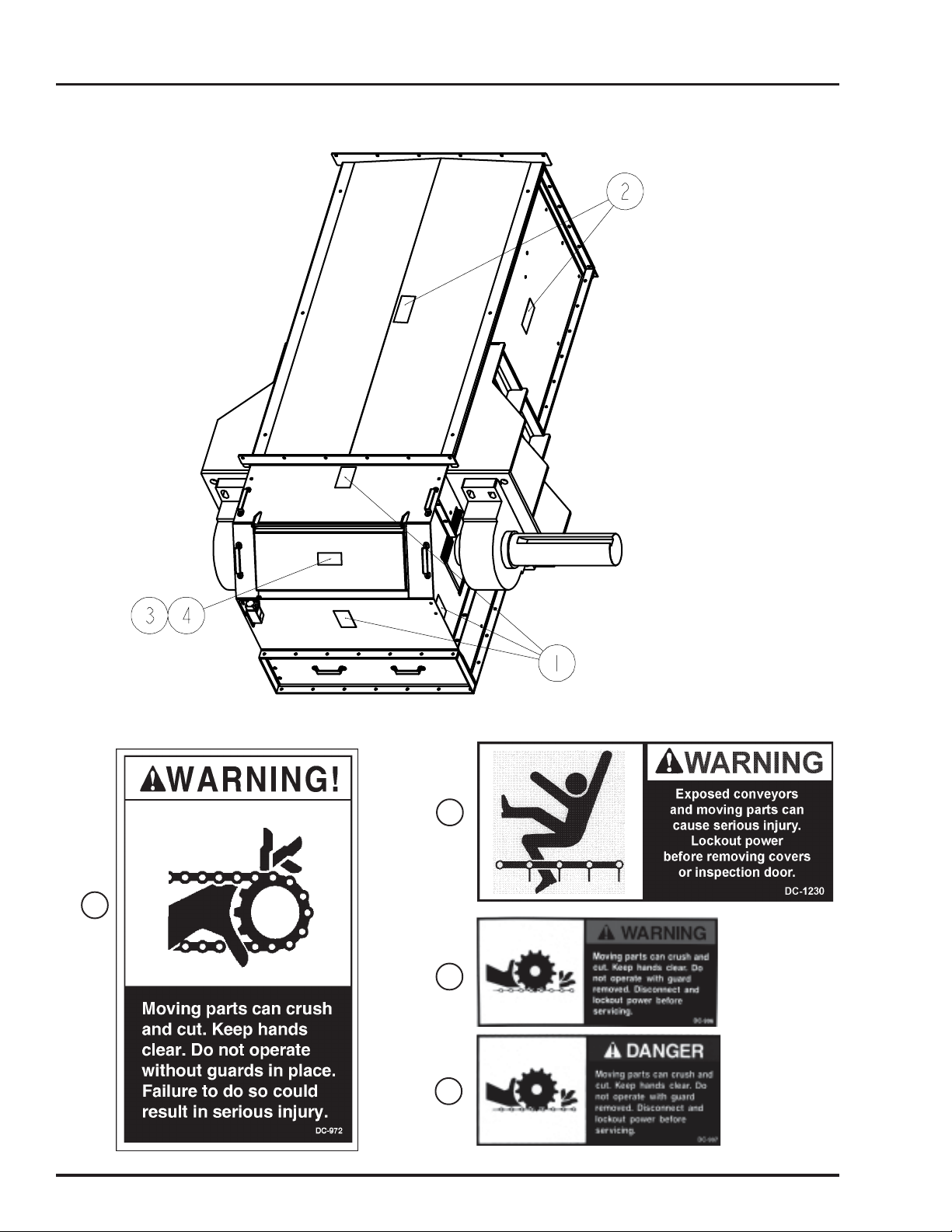
Head Safety Decals
Series 2 Chain Conveyors
Head Section Decal Locations
Decal 3 Outside
Decal 4 Inside
1
2
3
4
6
Page 7
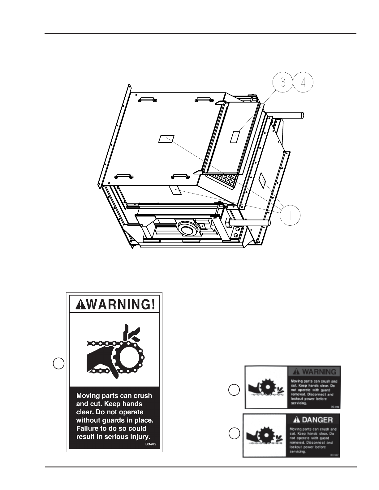
Series 2 Chain Conveyors
T ail Safety Decals
Tail Section Decal Locations
Decal 3 Outside
Decal 4 Inside
1
3
4
7
Page 8

General Precautions
General Precautions
CAUTION:
Series 2 Chain Conveyors
! Do not operate the unit before reading
and understanding the operator’s manual.
! Keep all safety shields and devices in
place.
! Keep all covers in place.
! Make certain everyone is clear of the
equipment before operating.
! Keep hands, feet and clothing away from
moving parts.
! Shut off and lock out all power to adjust,
service, clean or unclog.
! Keep children, visitors and all untrained
personnel away from the machine while
in operation.
! Do not operate electric motor equipped
units until motors are properly grounded.
! Disconnect power on electrical driven
units before resetting motor overloads.
!!
! Do not repetitively stop and start the drive
!!
in order to free a plugged condition. Jogging
the drive in this type of condition can damage
the conveyor and/or drive components.
! Keep off the equipment at all times.
8
Page 9

Series 2 Chain Conveyors
Receiving Inspection
Receiving Inspection
Carefully inspect the shipment as soon as it is received.
V erify that the quantity of parts or packages actually
received corresponds to the quantity shown on the packing slip. Any discrepancies should be clarified immediately . Please remember that any damage or missing
parts must be noted on the bill of lading at the time of
delivery . Report any damage or shortage to the delivering carrier as soon as possible. GSI’ s responsibility
for damage to the equipment ends with acceptance by
the delivering carrier.
Save all paperwork and documentation furnished with
any of the enmasse conveyor components.
Pre-Installation Preparation
Familiarize yourself thoroughly with this manual and all
the conveyor parts. Read the operators manual and all
safety signs before using or servicing equipment. T aking the time to do so will aid in the assembly of your
conveyor.
Remove any banding and crating material. Arrange all
the conveyor components in such a fashion that all are
easily accessible.
Locate sturdy items to serve as blocking (i.e. wood
blocks, saw horses, etc.). Blocking is used to support the conveyor sections above the ground to help
in assembly. Locate and place the conveyor sections on the blocking in order, starting with the head
section and concluding with the tail section.
9
Page 10

Installation
The head and tail sections of the chain conveyor are shipped pre-assembled direct from the factory . Intermediate trough sections come both factory pre-assembled or unassembled. Your order will serve as a reference to
how your trough section should arrive. If you have any questions, please refer to your order confirmation.
Series 2 Chain Conveyors
Head Assembly
T ail Assembly
10
Intermediate T rough Assembly
Typical Intermediate Trough Section Assembly
Page 11

Series 2 Chain Conveyors
Intermediate Trough Section Assembly
An en masse conveyor may be purchased with
unassembled trough sections. The following recommendations may prove useful in their assembly .
Before assembling conveyor trough sections together
remove covers. It is recommended that you store your
covers in a protected area in order to minimize any possible damage. Remember to retain factory shipped hardware for conveyor cover installation.
T ake a moment to familiarize yourself with your trough
assembly. Install the slide rail returns so that the wide
ends of the rail returns face away from the dischar ge end
of the conveyor. The narrow end, therefore, will face
toward the discharge end.
Installation
After making sure the flanges are aligned, tighten all
hardware on the trough section. Abrasion Resisting
(A.R.) liners are installed with the 3/8” flat countersunk
hardware provided. Adequately tighten liners to conveyor sides. Check that the countersunk hardware is
not protruding above the surface of the A.R. liners.
During assembly of each trough section to the next section, carefully inspect each flange joint to ensure that the
inside bottom and side surfaces of the troughs are flush.
A chalk line is helpful during this phase of the assembly
to ensure the proper alignment of the trough surfaces.
The maximum run-out in any direction should be
+/- 1/4”. This proper alignment will minimize wear on
flights and other potential damage to the conveyor. Make
sure the conveyor is level in horizontal applications.
Intermediate trough sections are supplied in standard
ten foot (10’) lengths. Depending on your application
and individual specifications however, shorter sections
may be required to accommodate a desired overall length.
Lay bottom plate weldment onto blocking material.
Next, loosely attach side weldments to bottom plate
with 3/8” hardware provided. Then fasten slide rail
return weldment to intermediate sides with the 1/2”
hardware.
Note: It is critical for straightness of the conveyor
that the sides and bottom flanges are aligned flush.
Also, it is important that the inside dimensions of
the box measure equidistant from side-to-side both
top and bottom of the trough box (Dimension A =
Dimension B). See diagram below .
Proceed by attaching the head and tail assemblies using
the same alignment procedures and precautions noted
in the preceding paragraph.
Cover Assembly
Installation
Fasten covers to the enmasse conveyor with the 3/8”
and 1/2” hardware provided. Adequately tighten the
1/2” bolts and nuts so that the vertical cover seams are
in tight contact with each other.
When an inlet is on the conveyor, a cover section may
have to be cut accordingly to accommodate the inlet.
For installation of an inlet, see Inlet Assembly and
Installation below.
Inlet Assembly and Installation
One inlet is typically provided per conveyor . GSI’s recommendation for inlet installation includes a minimum
distance of no less than 6” between the closest edge of
the inlet and the tail assembly . See detail on page 12.
End View of Trough Section
(Liners not shown for clarity)
The inlet can be attached with continuous weld seams.
If intermittently welded, it is important to use caulking
or sealing around the inlet area in order to seal the unit.
Similarly GSI recommends that if inlets are welded onto
the conveyor, this procedure should occur prior to installation of motor and/or other electrical devices. By not
following this precaution, owner assumes all risks associated with this type of installation.
11
Page 12

Installation
Series 2 Chain Conveyors
Inlet Assembly
Standard Inlet
Head Discharge End
T ail End
12
Page 13

Series 2 Chain Conveyors
Installation
Drag Chain Assembly Installation
All chain supplied with new conveyors will be
installed in a similar manner, regardless of type.
Correct total chain length has been determined for
your installation by GSI. The conveyor drag chain
is shipped in approximate 10 foot lengths with an
additional pre-cut short section if necessary (refer
to packing list). If welded chain (WH132, WH155
or WH157) has been supplied with the conveyor,
a minimum of five (5) feet of chain with cottered
pin connectors will be supplied. These pin connectors and links may be removed as necessary for
chain take-up. The chain may be installed at any
time during conveyor assembly .
It is recommended however , that you position the
chain over the slide rail returns and the sprockets in the head and tail assemblies. The UHMW
wear pads should be in front of the welded chain
flights in the direction of chain travel (see diagram below). Connect chain lengths together
with connecting links and/or pins.
Tighten the drag chain assembly using the take-up
screws located on each side of the tail section or on
the take-up head. The chain should be able to be
lifted slightly when sufficiently tightened. After the
chain is tight, check that the head and tail shafts are
square to the box sides. If the shafts are not square,
loosen the tighter of the two take-up screws until
the shafts are square. Lock the take-up screws by
tightening the jam nuts.
Rotate the chain, now on the sprockets, at least
one complete revolution. Check to see that the chain
and its wear pads are not catching on flanges or
rubbing on the trough liners. Ensure a “break-in”
period whereby the chain is allowed to run and
seat itself. After running it for an adequate period
of time stop the machine, disconnect and lockout
the power source. Retighten as necessary and remove any excess chain portions. Repeat this process as necessary.
Direction of Chain Travel
Bottom Run
13
Page 14

Installation
Installing Shaft Mount Reducers
Series 2 Chain Conveyors
Assemble torque arm bracket to conveyor per installation instructions found on page 17.
T o aid in the installation of the reducer onto the shaft,
remove any protective coating film from shaft. Slide
the reducer onto the drive shaft extending from the
side of the conveyor head section. Using the instructions and hardware supplied with the reducer, assemble
it to the conveyor drive shaft.
Assemble motor mount to the reducer . Refer to installation instructions provided with motor mount.
Install the rear panel of the drive guard before
mounting the sheaves. The rear panel has four (4)
mounting brackets with slotted holes. Attach the
lower brackets to the matching reducer assembly
bolts. Attach the upper brackets to the matching holes
in the front motor mount support.
Assemble the V-belt driven sheave to the input shaft of
the shaft mount reducer . Slide the sheave hub onto the
shaft and insert the square key . Attach the hub sheave
using the supplied retaining screws. The retaining screws
pass through the non-threaded holes of the hub and
into the sheave. Align the driver and driven sheaves
and tighten the retaining screws. During tightening, it is
possible for the sheave to move out of alignment or
become out of square. For maximum V-Belt life,
the driven sheave should remain both perpendicular to the drive shaft and aligned with the drive
sheave. Slip the V-belts over both the driver and
driven sheaves.
Adjustment of V-belt tension is achieved by tightening the hex nuts located on the four (4) jackscrews
of the motor base. Adjust motor base equally at all
four jackscrews to maintain shaft alignment. Belts
are designed to fit loose upon installation. When
the V-belt tension is correct, tighten the top nut on
the jackscrews to lock the motor base in position.
Proper tension is 1/64” of deflection per one (1”)
inch of sheave centers on one side of belt, centered between sheaves.
Note: T oo much tension shor tens belt life. Check
belt tension frequently during the first 24-48 hours
of operation.
Install the front drive guard panel over the four
corner mounting studs. Secure with washers and
nuts provided.
Fill the shaft mount reducer with the manufacturer’s
recommended oil. A list of recommended oil can
be found in the gear reducer instructions.
14
Page 15

Series 2 Chain Conveyors
Installation
Welding
W elding on or to the conveyor may cause damage to
both the conveyor and its electrical system. If welding
is necessary , measures should be taken to protect the
conveyor . Should it be necessary to fasten anything to
the conveyor permanently , careful consideration should
be given to methods of maintenance, removal and replacement of the conveyor and/or its parts. (please
refer to Inlet Installation for GSI recommended guidelines).
Motor
Connect the conveyor motor to a power source according to the motor manufacturer’s instructions and
recommendations. T o avoid injury it is recommended
that a certified electrician perform the motor wiring.
A shut off switch should be placed near the motor so
that the system may easily be shut down to help prevent accidents during maintenance. It is important to
check proper motor shaft rotation before installing drive
belts
Clearance
A clearance of at least the width of the conveyor is
recommended on all sides of the unit. Less clearance may be acceptable however, serious consideration must be given to methods of maintenance,
removal and replacement of the conveyor and/or
its parts.
Discharge
The standard conveyor is constructed with one discharge located at the drive end. If intermediate discharges are to be used, the location(s) must be determined before proceeding with the conveyor assembly .
Intermediate discharges cannot be installed over a
trough joint; therefore, it may be necessary to position
a shorter trough section to serve as a spacer in order
to accommodate the placement of the discharge(s)
where they are required.
The owner assumes all responsibility for any alterations
to the equipment.
Support
GSI’ s recommended general guidelines in this area include adequate support for the conveyor assembly to
be installed at intervals no greater than 10 feet. It is
recommended that supports be installed at vertical portions of flanges leaving bottoms of trough sections
clear. By attaching supports in this manner , the removable bottoms are unobstructed for ease of replacement. Support legs are available as an option.
15
Page 16

Care and Maintenance
Care and Maintenance Storage
Series 2 Chain Conveyors
WARNING!
Before any maintenance is performed to the conveyor , power must be shut off
and locked out to prevent accidental start up!
The care and maintenance section is provided with the
intention of helping to extend the useful life of the unit.
Like all equipment, the useful life of the conveyor is
greatly reduced if not used wisely and well maintained.
Please follow the next few simple steps to insure the
safety and longevity of your equipment.
!!
! Check all bearings and moving parts daily
!!
during use.
!!
! Lubricate bearings according to bearing
!!
manufacturer’s recommendations.
If the unit is to be inactive for an extended period,
the following procedures are recommended.
!!
! Thoroughly clean the unit.
!!
!!
! Loosen the drag chain tension. Doing so
!!
relieves the stress placed on the bearings
and shafts of the drive and tail sections.
!!
! Lubricate drag chains, shafts and drive
!!
components with a good grade of light
machine oil.
!!
! Follow manufacturer’s recommendations for
!!
gear reducer lubrication and maintenance.
!!
! Inspect the V-belts periodically for proper
!!
tension and wear. V-belts should be
replaced as necessary . If replacement or
tension adjustment is required, please refer to
the Shaft Mount Reducer Assembly Section
on page 14.
!!
! The Drag Chain and Sprockets should be
!!
checked periodically for wear, damage and
proper adjustment. Any broken or bent
paddles should be replaced or straightened.
Should adjustment or replacement of the
drag chain be required, refer to the
Assembly Section on page 13.
16
Page 17

Series 2 Chain Conveyors
T orque Arm Bracket Installation
Options
When a drive package is ordered with the conveyor
system, a torque arm bracket is provided.
The torque arm bracket is pre-punched for ease of
installation to the unit. Begin installation of this
option by first determining the location of the torque
arm bracket relative to the range of extension allowed by the shaft mount reducer’s torque arm. The
bracket will extend on the same side of the conveyor as the head shaft. Remove the 5/8” bolts necessary from the bottom of the conveyor head bottom plate.
Set the torque arm bracket in place and attach with
the 5/8” hardware previously removed from the
bottom plate of the conveyor. Four (4) 5/8” bolts
and nuts are required to fasten the torque arm
bracket to the conveyor.
Install shaft mount reducer to head shaft per instructions on page 14.
Next, match the size of the hardware to the reducer
manufacturer’s torque arm. Use this hardware to attach the torque arm to the bracket. Adequately tighten
all hardware.
T orque Arm Bracket
Inspection Ports
After determining location(s) for the inspection
port(s) on conveyor, cut an 1 1-3/4” square hole in
the cover for each inspection port. Cut the square
opening so that it is centered over the peak of the
conveyor cover.
Position the inspection port over the square hole
until its frame is flush to the cover. Weld inspection port to conveyor cover. Additional caulking
may be required so that water will shed from the
inspection port.
17
Page 18

Options
Series 2 Chain Conveyors
Plug Relief Door
GSI Series 2 26” and 32” tall enmasse conveyors
come equipped with a head discharge plug relief
door as a standard feature. A NEMA 4 heavy duty
limit switch is standard on the relief door .
However, in extremely dirty , dusty conditions and/
or in enclosed environments, a NEMA 9 heavy duty
limit switch should be used on the plug relief door.
The NEMA 9 limit switch is available as an added
option.
The optional NEMA 9 limit switch (GSI part number CE-00504) attaches to the same universal
bracket on the front of the head assembly as the
standard NEMA 4 limit switch. The same hardware
is used for both limit switches.
Note: The limit switch bracket must be oriented
as shown for proper engagement between limit
switch and Plug Relief Door .
Attach the bracket to the hood cover with two (2)
5/16” bolts and nuts where two pre-punched holes
are located. Two pairs of pre-punched holes are
provided on the removable head hood cover - one
pair on the left side and one pair on the right side
of hood cover. Next, use two (2) #10 machine
screws, nuts and washers to fasten the limit switch
to the bracket. The limit switch can be installed
either to the left or to the right. Do not tighten these
machine screws at this time.
Adjust the limit switch so that the actuator arm keeps
sufficient tension against the Plug Relief Door . After the limit switch is properly positioned, tighten
the two machine screws.
Standard Plug Relief Door Limit Switch
18
Optional NEMA 9 Limit Switch
GSI part # CE-00504
Page 19

Series 2 Chain Conveyors
Slack Chain Assembly
The GSI Group offers a slack chain detector
system as an option for its 26” and 32” tall Series
II enmasse conveyors. Depending on working
conditions and/or environment, either a NEMA 4
or a NEMA 9 limit switch is available.
Begin installation of optional slack arm assembly by
first cutting a 12” x 5” rectangular hole in the head
section cover; see illustration below.
Next, center the slack chain assembly over the
rectangular opening. Mark the locations for the
four (4) 7/16” diameter holes. Temporarily remove the slack chain assembly , and drill the four
7/16” diameter holes.
Options
Before attaching slack chain assembly to the
conveyor, apply sealant to bottom surfaces of
slack chain assembly.
Fasten slack chain assembly to conveyor with 3/8”
hardware. See illustration below regarding direction of slack chain assembly on the conveyor.
After installation, check that the clearance between the UHMW paddle in the slack chain
assembly and the UHMW flights on the chain is
approximately 1/2” to 3/4”. Adjust if necessary.
Top Mount Slack Chain
with NEMA 4 limit switch
Top Mount Slack Chain
with NEMA 9 limit switch
19
Page 20

20
Optional Carry-over Bars
Carry-Over Bars - Reversing Conveyor
Series 2 Chain Conveyors
For applications where the enmasse conveyor may
run in a reversing direction, carry-over bars should
be installed in the head assembly. These bars will
ensure a smooth transition of the chain and flights
from the head discharge into the conveyor box.
The carry-over bar package consists of four (4)
carry-over bars, four (4) clips, and two (2) shims
plus the hardware necessary to attach these components within the head assembly.
Pre-assemble the two pairs of carry-over bars
and clips using the 3/8” bolts and nuts. Be sure to
center the clips to the vertical slots on each end
of the carry-over bars.
Next, place the pre-assembled pairs of carry-over
bars in the head discharge as shown below. It is
imperative that these carry-over bars be spaced
so that they pick up the UHMW flights as shown
below.
After the two pairs of carry-over bars have been
positioned, mark the locations for the eight (8)
9/16” diameter holes and drill. Attach with the
1/2” hardware provided.
After installation, check that the top edge of the
carry-over bars does not extend above the top surface of the bottom plate.
Page 21

Series 2 Chain Conveyors
Trouble Shooting Guide
Problem Cause Solution
Low capacity Improper chain speed Check the shaft RPM
Improper feed Check the grain level at inlet
Plugging Check the discharges
Noisy operation Loose UHMW Paddles Check all bolts on chain
Bottom or Sides Not Aligned Check Intermediate Trough Section
joints and make flush
W orn Drive Components Check oil level and shaft seals
belt misalignment; loose belts
W orn Sprocket Replace
Return Rail Alignment Check Rail Alignment
Trouble Shooting
Uneven UHMW Conveyor Misalignment Check the conveyor alignment
paddle wear Sprocket Slipped Check set screws on sprockets
Return Rail Alignment Check Rail Alignment
Excessive carry-over Gates Not Fully Opening Check the gate operation
Uneven sprocket wear W orn chain Replace chain (see pg. 13)
Improper alignment Check the sprocket alignment
Material carry-over Check for improper location
into discharge sprocket of inlet (see pg. 11)
Consult your contractor for added assistance.
21
Page 22

Training Sign-Off Sheet
Series 2 Chain Conveyors
Employer/Employee Training Sign Off Sheet
GSI is making every effort to warn, guard, and educate the consumer when using the various kinds of
equipment that we manufacture. GSI has included this sign off sheet for you and your staff to use in the
training process on installation and operation of the equipment described in this manual. Read the entire
manual, sign off, and date on chart below.
22
Page 23

Series 2 Chain ConveyorsSeries 2 Chain Conveyors
Series 2 Chain Conveyors
Series 2 Chain ConveyorsSeries 2 Chain Conveyors
WarrantyWarranty
Warranty
WarrantyWarranty
The GSI Group, Inc. Warranty
THE GSI GROUP, INC. (“GSI”) WARRANTS ALL PRODUCTS WHICH IT MANUFACTURES TO
BE FREE OF DEFECTS IN MATERIAL AND WORKMANSHIP UNDER NORMAL USAGE AND
CONDITIONS FOR A PERIOD OF 12 MONTHS AFTER RETAIL SALE TO THE ORIGINAL END
USER. THE PURCHASER’S SOLE REMEDY AND GSI’S ONLY OBLIGATION SHALL BE TO
REPAIR OR REPLACE, AT GSI’S OPTION AND EXPENSE, PRODUCTS THAT, IN GSI’S SOLE
JUDGMENT, CONTAIN A MATERIAL DEFECT DUE TO MATERIALS OR WORKMANSHIP.
ALL DELIVERY AND SHIPMENT CHARGES TO AND FROM GSI’S FACTORY WILL BE
PURCHASER’S RESPONSIBILITY. EXPENSES INCURRED BY OR ON BEHALF OF THE
PURCHASER WITHOUT PRIOR WRITTEN AUTHORIZATION FROM AN AUTHORIZED
EMPLOYEE OF GSI SHALL BE THE SOLE RESPONSIBILITY OF THE PURCHASER.
EXCEPT FOR THE LIMITED WARRANTY EXPRESSED ABOVE, GSI MAKES NO FURTHER
WARRANTY OF ANY KIND, EXPRESS OR IMPLIED, INCLUDING, WITHOUT LIMITATION,
WARRANTIES OF MERCHANTABILITY OR FITNESS FOR A PARTICULAR PURPOSE OR
USE IN CONNECTION WITH (I) PRODUCT MANUFACTURED OR SOLD BY GSI OR (ii) ANY
ADVICE, INSTRUCTION, RECOMMENDATION OR SUGGESTION PROVIDED BY AN AGENT,
REPRESENTATIVE OR EMPLOYEE OF GSI REGARDING OR RELATED TO THE
CONFIGURATION, INSTALLATION, LAYOUT, SUITABILITY FOR A PARTICULAR PURPOSE,
OR DESIGN OF SUCH PRODUCTS.
GSI SHALL NOT BE LIABLE FOR ANY DIRECT, INDIRECT, INCIDENTAL OR
CONSEQUENTIAL DAMAGES, INCLUDING, WITHOUT LIMITATION, LOSS OF ANTICIPATED
PROFITS OR BENEFITS. PURCHASER’S SOLE AND EXCLUSIVE REMEDY IS AS SET FORTH
IN THE LIMITED WARRANTY EXPRESSED ABOVE, WHICH SHALL NOT EXCEED THE
AMOUNT PAID FOR THE PRODUCT PURCHASED. THIS WARRANTY IS NOT
TRANSFERABLE AND APPLIES ONLY TO THE ORIGINAL PURCHASER. GSI SHALL HAVE
NO OBLIGATION OR RESPONSIBILITY FOR ANY REPRESENTATIONS OR WARRANTIES
MADE BY OR ON BEHALF OF ANY DEALER, AGENT OR DISTRIBUTOR OF GSI.
GSI ASSUMES NO RESPONSIBILITY FOR CLAIMS RESULTING FROM ERECTION DEFECTS
OR UNAUTHORIZED MODIFICATIONS TO PRODUCTS WHICH IT MANUFACTURED.
MODIFICATIONS TO PRODUCTS NOT SPECIFICALLY DELINEATED IN THE MANUAL
ACCOMPANYING THE EQUIPMENT AT INITIAL SALE WILL NULLIFY THE PRODUCT
WARRANTY THAT MIGHT HAVE BEEN OTHERWISE AVAILABLE.
THE FOREGOING WARRANTY SHALL NOT EXTEND TO PRODUCTS OR PARTS WHICH
HAVE BEEN DAMAGED BY NEGLIGENT USE, MISUSE, ALTERATION OR ACCIDENT. THIS
WARRANTY EXTENDS SOLELY TO ONLY PRODUCTS MANUFACTURED BY GSI. THIS
WARRANTY IS EXCLUSIVE AND IN LIEU OF ALL OTHER WARRANTIES EXPRESS OR
IMPLIED. GSI RESERVES THE RIGHT TO MAKE DESIGN OR SPECIFICATION CHANGES AT
ANY TIME.
PRIOR TO INSTALLATION, PURCHASER HAS THE RESPONSIBILITY TO COMPLY WITH
ALL FEDERAL, STATE AND LOCAL CODES WHICH MAY APPLY TO THE LOCATION AND
INSTALLATION OF PRODUCTS MANUFACTURED OR SOLD BY GSI.
PHLEGAL: #1832020 v1 (139LG01!.DOC) (revised December 2005)
23
Page 24

Page 25

Series 2 ConveyorsSeries 2 Conveyors
Series 2 Conveyors
Series 2 ConveyorsSeries 2 Conveyors
MATERIAL HANDLING
1004 E. Illinois St., Box 20
Assumption, IL 62510-0020
phone: 217-226-4421
fax: 888-741-3004
www.grainsystems.com
October 2006
25
 Loading...