

Page 1
WIRE GRILL GUARD ROOF VENT
PNEG-104
Wire Grill Guard Roof Vent Assembly & Installation Instructions
The following instructions are for assembling and installing the Wire Grill Guard Roof Vent. First,
check the packing list to ensure all components have been shipped. The unit is easiest assembled in
the upside down position as shown in the instructions. Roof vent location should be as shown on
the reverse page.
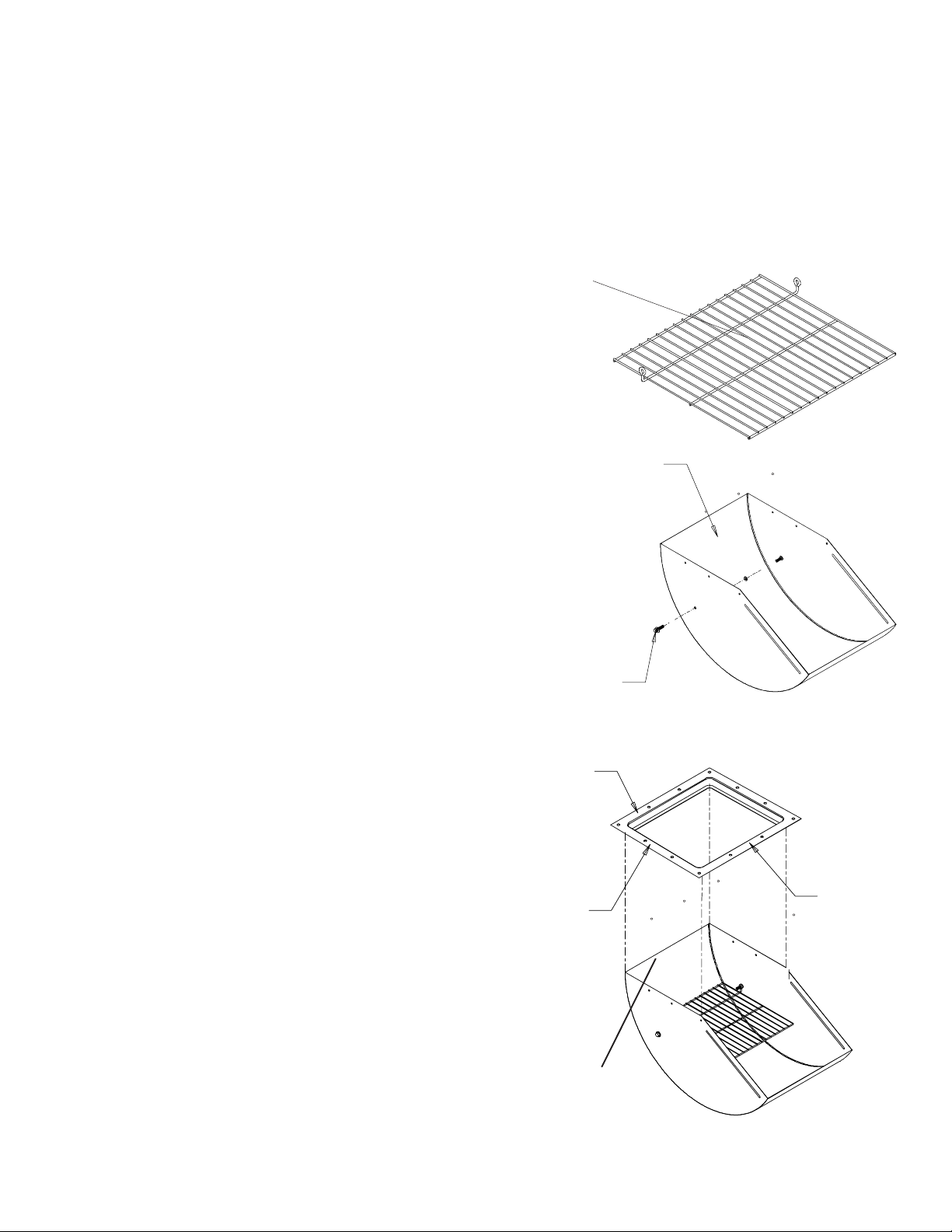
Grill Guard
(MIS-6766)
ASSEMBLY
1. T ake all parts out of the shipping box and check
if all parts are present.
2. Turn one (1) roof vent housing (MIS-6778) upside down. (See Figure #1)
3. Insert 5/16" x 1.1/4" bin bolt with neoprene
washer through hole in the side of the roof vent.
Place jamb nut onto the bolt and tighten. (See Figure #1).
Vent Housing Assembly
(MIS-6778)
4. Slide on eyelet of Grill Guard onto the 5/16" bin
bolt.
5. Insert 5/16" x 1.1/4" bin bolt with neoprene
washer through the other side of the roof vent,
through jamb nut and other eyelet of Grill Guard.
Tighten nut against vent housing side.)
6. Apply a bead of tube caulking around three(3)
housing sides of the roof vent where it meets the
holddown angle.
7. Place holddown angle (MIS-4404) on the assembled roof vent. The wide end of the hole-down
angle must face vent discharge. Once aligned, screw
nine (9) #10 self drilling (S-280) screws through the
roof housing and into the holddown angle. (See Figure #2).
5/16" x 1.1/4"
Nuts & Bolts
Short Side
Approx.
15.3/8"
Hold-Down
Angle
(MIS-4404)
Figure #1
Long Side
Approx.
15.7/8"
Caulk with tube caulking
(Three sides of vent housing)
Figure #2
Page 2
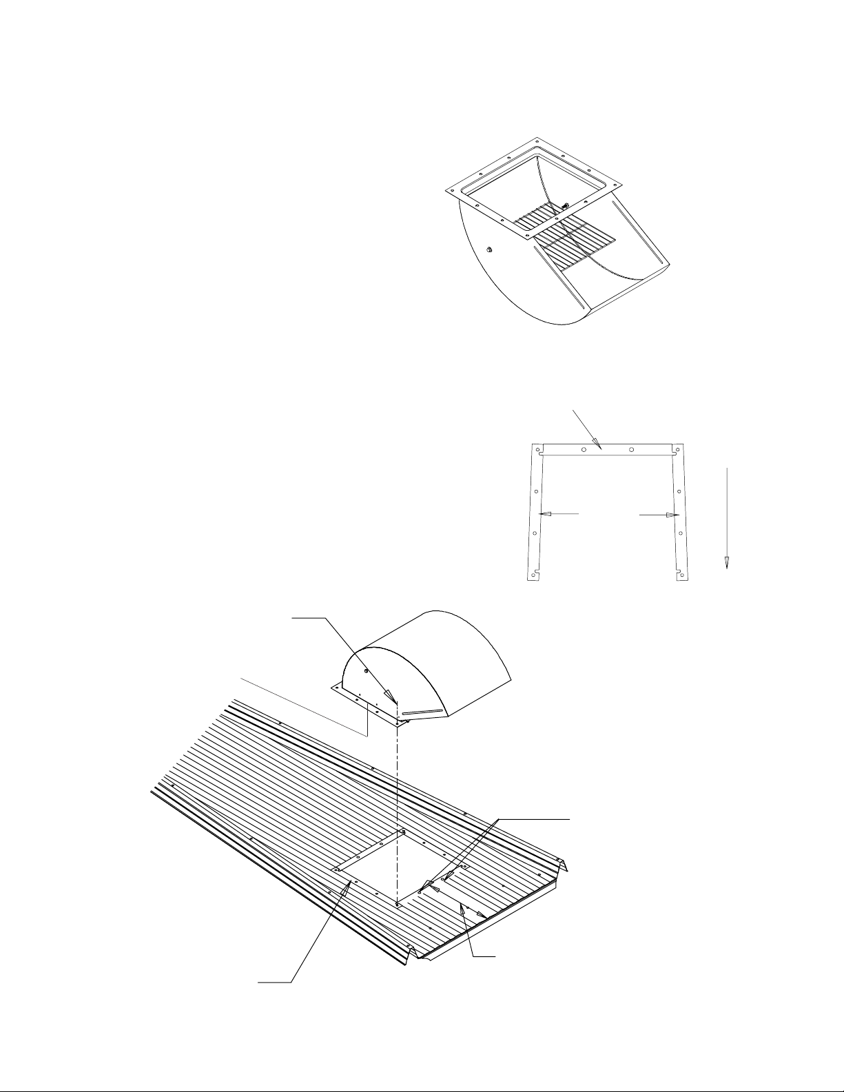
Wire Grill Guard Roof Vent Installation
Installation
8. If the roof sheet does not have a prepunched
hole for the roof vent, a hole must be cut. The cut
hole should match the roof vent. The hole inside
edge should be approximately fifteen (15) inches
from the eave. (See Figure #5)
9. Place the three (3) foam strips on roof sheet, as
shown in Figure #4. Position roof vent over foam
strips and bolt down using 5/16" x 3/4" bin bolts and
nuts. (Note: See instructions below for lower two
(2) bolts of vent).
Figure #3
5/16" x 3/4" Nuts & Bolts
(12 Required)
Caulk with tube caulking
(Three sides of vent housing)
Top Strip
(MIS-6780)
Approx. 15.7/8"
Short Side
Approx. 15.3/8"
Side Strips
(MIS-6781)
Roof Eave
Long Side
Figure #4
Foam Strips
(1) Top (MIS-6780)
(2) Sides (MIS-6781)
NOTE: Install bolts for these
two (2) holes with the bolt
head and neoprene washer to
the underneath side of the
roof sheet and the nut against
the vent holddown angle.
Caulk holes.
Approx. 15"
Figure #5
 Loading...